air cooled water chiller with centrifugal fans - trane hk 0601.pdf · air cooled water chiller with...
TRANSCRIPT
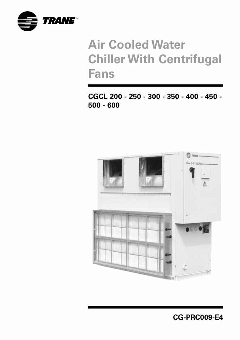
Air Cooled Water
Chiller With Centrifugal
Fans
CGCL 200 - 250 - 300 - 350 - 400 - 450 -500 - 600
CG-PRC009-E4

©American Standard Inc. 2001
Contents
Features And Benefits 3
General Data 5
Condenser Fan Performance 6
Pressure drop through condenser coil and air filter 7
Application Considerations 8
Performance Data 9
Typical Wiring 14
Dimensional Data 18
Mechanical Specifications 21
CG-PRC009-E4 3
Features and benefits
InstallationMounting on site
The compact size of the CGCLsimplifies the installation on site andits low wide profile allows it to passeasily through a door. The total areataken up by the unit is relativelysmall due to the reduced size.Anti-vibration pads are supplied asstandard to avoid direct contactbetween the unit base and themounting surface.
Water connections
The water connections are broughtto the outside of the unit so that it isnot necessary to remove or piercethe panels.
Electrical connections
Electrical cable gland located on theback of the panel allow for easyconnection of the power cable.A flow detection system is mountedas standard in the factory. It istherefore not necessary to fit a FlowSwitch on site.A dry contact is available on thecontrol module to control the waterpump contactor. Space is availablein the control panel to install thechilled water pump contactor(s).Water pump contactor can beinstalled by Trane as an option.
Reliable and quiet operationReliability
The use of the Scroll compressorsensures excellent reliability. Versus areciprocating compressor, the Scrollhas the following advantages.- 64 % fewer parts.- The Scroll compressor generatessignificantly less vibration thereforereducing the risk of discharge linefailure.
Performance
The absence of dead volume at theend of the compression cycleensures better performance.The absence of fragile moving parts,such as springs and valves, alsomeans that this performance ismaintained with time.
Part load performance
The Scroll compressor alwaysoperates at full load.The chiller capacity is a function ofthe number of compressors running.In this way the power factor ismaintained at a high level even atlow loads.
Low sound level
The Scroll compressor issignificantly less noisy andgenerates less vibration than areciprocating compressor.In addition, on sites where the noiselevel is critical, the compressors canbe fitted with an optional soundattenuating enclosure.
Reduced maintenance
The Scroll compressor does notrequire routine maintenance due tothe absence of fragile parts, such assprings and valves which requireregular replacement.
Other standard features• Thermal insulation of the water
connections, and of theevaporator.
• Loss of water flow protectionprovided by a differentialpressostat.
• Operation up to + 40°C externaltemperature.
• Shipped with rubber pads.• Centrifugal fans which allow to
obtain a static pressure up to500 Pa.
• A resistance heater placed on theevaporator to avoid freeze-up risk.The heater is energized only if theexternal temperature isbelow + 2°C.
• Pressure transducers to obtain anoptimal control of the fans and toallow to display the low and highrefrigerant pressure.
• Modem connection.• Electrical panel IP 55.

4 CG-PRC009-E4
Control module SMM
(Scroll Manager Module)
Leaving chilled water
temperature controlThe chilled water temperature ismeasured at the evaporator outlet.The SMM module compares thisvalue with the setpoint and starts orstops the compressors following aPID algorithm.
Condensing pressure control
The SMM module controls the fanspeed operating in a way whichalways optimizes the COP and avoidHP or LP cut out.
Control
The SMM module includes thefollowing functions:• Short cycle protection taking into
account the frequency ofcompressor starts.
• Automatic restart after a powerfailure.
• Equalization of the number ofstarts and the operating hours ofthe compressors.
• Control of the chilled water pump.• Control of the evaporator anti-frost
heater.• Control of all safety and
protection.
Optimization
In order to reduce electricityconsumption the SMM module canautomatically adjust the chilledwater temperature setpoint inrelation to the outdoor temperature.
Communication
The SMM module can interface withdifferent types communicationsystems. These systems simplifyconsiderably the maintenance andcan supply information on theoperating conditions of the chiller.
Operator interface
The SMM module includes acommunication interface with aliquid crystal display. This interfaceprovides an accurate assessment ofthe chiller operating conditions andfacilitates a rapid diagnosis if asafety function is activated.
Remote control
The dry contacts and the analoginputs, provided as standard, allowfor the remote control andsurveillance of the chiller.If a safety function is activated anoutput via a dry contact is provided.Inputs are available to partially orcompletely stop the operation of thechiller. An analog input (4/20 mA or0/10 V) allows for the adjustment ofthe chilled water temperaturesetpoint.
Remote control via serial link
It is possible to integrate the CGCLunit into a BMS via a serial link withan optional TCI-S comunication card.The TCI-S allows to obtain a seriallink type RS232 or RS485 with aModbus protocol.

CG-PRC009-E4 5
General Data
Table 1 - CGCL general dataCGCL CGCL CGCL CGCL CGCL CGCL CGCL CGCL
200 250 300 350 400 450 500 600
R407C R407C R407C R407C R407C R407C R407C R407C
Performances (1)
Cooling Capacity kW 48.9 60.7 73.5 86.3 100.1 109.8 125.0 149.7Power input kW 19.9 24.7 28.0 34.7 42.7 47.0 50.6 59.7Pressure drop kPa 42 41 42 41 39 46 56 68Main Power supply 400/3/50Sound Power Level 300 Pa dB(A) 88 84 87 89 91 94 90 94Sound Power Level 400 Pa dB(A) 90 86 89 90 93 95 92 95Sound Power Level 500 Pa dB(A) 91 88 90 92 94 96 93 96
System Data
Refrigerant Circuit 1 2Compressor
Number 2 3 4Type ScrollModel 10T+10T 10T+15T 2x15T 2x10T+15T 10T+2x15T 3x15T 2x(10T+15T) 4x15TSpeeds number 1 1 1 1 1 1 1 1Motors Number 1 1 1 1 1 1 1 1Nominal Amps A 37 46 55 65 74 83 92 110Starting Amps A 138 193 202 212 221 230 239 257Motor RPM rpm 2900 2900 2900 2900 2900 2900 2900 2900
Heat Exchanger
Number 1Type Brazed plateModel V45-40 V45-50 V45-60 V45-70 V45-90 V45-90 DV47-102 DV47-134Water volume (total) l 4.7 5.9 7.0 8.2 10.5 10.5 12.3 16.1Antifreeze Heater W 65 130
Water Connections
Type: ISO R7 MaleDiameter 1 1/2" 2" 2 1/2"
Coil
Type Plate FinTube size mm 9.52Tube type SmoothHeight mm 914 1219 1219 1626Length mm 1829 1829 2743 2743Face Area m2 1.67 2.23 3.34 4.46Rows 4.0 4.0 4.0 4.0Fins per inch (fpf) 180.0 180.0 180.0 180.0
Control VA VA 800Fan
Type CentrifugalNumber 1 2 3Diameter mm AT 18-18Drive type Pulley + BeltSpeeds number 2Air flow m3/h Refer to table 2Static pressure Pa Refer to table 2Motors Number 1Motor kW Refer to table 2Nominal Amps A Refer to table 2Starting Amps A Refer to table 2Motor RPM (Low/ High) rpm Refer to table 2
Dimensions
Height mm 1997 1997 1997Length mm 2268 3230 3230Width mm 866 866 1216Weight uncrated kg 700 820 880 1080 1140 1200 1380 1500Weight crated kg 740 860 920 1130 1190 1250 1450 1570
System Data
Refrigerant circuit 1 1 1 1 1 1 2 2R407C Refrigerant Charge
Circuit A kg 12 15 15 23 23 23 15 15Circuit B kg - - - - - - 15 15
(1) Water temp 12/7°C outiside air temp 35°C(2) Without fan - refer to table 2 for fan amps

6 CG-PRC009-E4
Condenser Fan Performance
Table 2 - CGCL Fan performance
SizeAirflow Available Static Pressure (Pa)
(m3/h) 300 400 500
CGCL 200 15300
High speed * (kW) 0.75 1.1 1.1High Speed (KW) 4.0 5.5 5.5Nominal Amps Low speed * (A) 3.2 3.7 3.7Nominal Amps High speed (A) 8.9 11 11Starting Amps * (A) 14 12 12
CGCL 250 17800
High speed * (kW) 0.75 1.1 1.5High Speed (KW) 4.0 5.5 7.5Nominal Amps Low speed * (A) 3.2 3.7 5.0Nominal Amps High speed (A) 8.9 11 15.3Starting Amps * (A) 14 12 17
CGCL 300 23800
High speed * (kW) 1.5 1.5 2.8High Speed (KW) 7.5 7.5 11.0Nominal Amps Low speed * (A) 5.0 5.0 7.7Nominal Amps High speed (A) 15.3 15.3 21.5Starting Amps * (A) 17 17 33
CGCL 350 26800
High speed * (kW) 1.5 2.8 2.8High Speed (KW) 7.5 11.0 11.0Nominal Amps Low speed * (A) 5.0 7.7 7.7Nominal Amps High speed (A) 15.3 21.5 21.5Starting Amps * (A) 17 33 33
CGCL 400 30600
High speed * (kW) 2.8 2.8 3.8High Speed (KW) 11 11 15Nominal Amps Low speed * (A) 7.7 7.7 10.1Nominal Amps High speed (A) 21.5 21.5 28.6Starting Amps * (A) 33 33 43
CGCL 450 34500
High speed * (kW) 3.8 3.8 4.8High Speed (KW) 15.0 15.0 18.5Nominal Amps Low speed * (A) 10.1 10.1 12.1Nominal Amps High speed (A) 28.6 28.6 34.6Starting Amps * (A) 43 43 45
CGCL 500 39100
High speed * (kW) 2.8 3.8 3.8High Speed (KW) 11.0 15.0 15.0Nominal Amps Low speed * (A) 7.7 10.1 10.1Nominal Amps High speed (A) 21.5 28.6 28.6Starting Amps * (A) 33 43 43
CGCL 600 47600
High speed * (kW) 4.8 4.8 5.3High Speed (KW) 18.5 18.5 22.0Nominal Amps Low speed * (A) 12.1 12.1 13.2Nominal Amps High speed (A) 34.9 34.9 40.9Starting Amps * (A) 45 45 48
*: Fan motor always start in Low speed
Unit nominal amps = nominal fan amps (according to static pressure) + compressor nominal amps
Unit starting amps = nominal fan amps (according tostatic pressure) + compressor starting amps

CG-PRC009-E4 7
Pressure drop through condenser coil
and air filter
Table 3 - Pressure drop
Unit Airflow Pressure drop (Pa)
m3/h Cds coil AR300 filter A150 Filter M8 Filter
CGCL 200 15300 96 100 66 28CGCL 250 17800 77 85 56 22CGCL 300 23800 124 122 84 40CGCL 350 26800 77 85 56 22CGCL 400 30600 96 100 68 28CGCL 450 34500 117 117 80 36CGCL 500 39100 124 95 64 26CGCL 600 47600 163 122 84 40

8 CG-PRC009-E4
Application considerations
Application of this product should bewithin the catalogued waterflow andperformance consideration.
Clearance requirements
The recommended clearancesidentified with unit di0mensionsshould be maintained to assureadequate serviceability, maximumcapacity and peak operatingefficiency. Actual clearances thatappear inadequate should bereviewed with the local TRANErepresentative.
Operating limits.
Condenser fan configuration
Table 4 - Operating limits R 407CMin. outdoor air temperature -5°CMin. outdoor air temperature + 40°CMin. leaving water temperature -12°C (37% glycol)Max. leaving water temperature + 12°C
Figure 1 - Fan arrangement
Table 5Unit Configuration nbr
1.0 2.0 2.1 3.0
CGCL 200 Yes Yes No YesCGCL 250 Yes Yes No YesCGCL 300 Yes Yes No YesCGCL 350 Yes Yes No YesCGCL 400 Yes Yes No YesCGCL 450 Yes Yes No YesCGCL 500 Yes Yes Yes NoCGCL 600 Yes Yes Yes No
1.0 2.0 3.02.1

CG-PRC009-E4 9
Performance Data
Table 6 - Cooling Capacities CGCL 200Outdoor Ambient Temperature
25°C 30°C 35°C 40°CCap P.I. HP LP Cap P.I. HP LP Cap P.I. HP LP Cap P.I. HP LPkW kW bar bar kW kW Bar bar kW kW bar bar kW kW bar bar
37 -12°C 27.2 12.0 14.5 2.9 25.9 13.5 16.6 2.9 24.4 15.2 18.8 2.933 -8°C 32.2 12.4 15.0 3.3 30.6 13.9 17.1 3.4 28.9 15.7 19.4 3.4 27.0 17.8 21.9 3.427 -4°C 37.7 12.8 15.6 3.8 35.8 14.3 17.7 3.8 33.8 16.2 20.0 3.9 31.6 18.4 22.6 3.920 0°C 43.6 13.2 16.2 4.3 41.5 14.9 18.4 4.4 39.1 16.8 20.7 4.4 36.6 19.0 23.4 4.410 4°C 49.9 13.7 16.9 4.9 47.4 15.4 19.1 4.9 44.8 17.4 21.5 5.0 42.0 19.7 24.2 5.00 5°C 51.7 13.8 17.1 5.1 49.2 15.6 19.3 5.1 46.4 17.6 21.8 5.1 43.5 19.9 24.4 5.20 6°C 53.2 14.0 17.3 5.2 50.6 15.7 19.5 5.2 47.8 17.7 22.0 5.3 44.8 20.1 24.6 5.30 7°C 54.8 14.1 17.5 5.4 52.1 15.9 19.7 5.4 49.2 17.9 22.2 5.4 46.1 20.2 24.9 5.50 8°C 56.4 14.2 17.7 5.5 53.6 16.0 19.9 5.5 50.7 18.1 22.4 5.6 47.5 20.4 25.1 5.60 9°C 57.9 14.4 17.8 5.7 55.1 16.1 20.1 5.7 52.1 18.2 22.6 5.7 48.8 20.6 25.3 5.80 10°C 59.5 14.5 18.0 5.8 56.6 16.3 20.3 5.8 53.5 18.4 22.8 5.90 11°C 61.1 14.6 18.2 6.0 58.1 16.4 20.5 6.0 54.9 18.5 23.0 6.00 12°C 62.6 14.7 18.4 6.1 59.6 16.6 20.7 6.1 56.3 18.7 23.2 6.2
Table 7 - Cooling Capacities CGCL 250Outdoor Ambient Temperature
25°C 30°C 35°C 40°CCap P.I. HP LP Cap P.I. HP LP Cap P.I. HP LP Cap P.I. HP LPkW kW bar bar kW kW Bar bar kW kW bar bar kW kW bar bar
37 -12°C 34.2 15.2 14.7 2.9 32.5 17.1 16.7 2.9 30.7 19.2 19.0 2.933 -8°C 40.4 15.8 15.2 3.4 38.4 17.7 17.3 3.4 36.2 19.9 19.7 3.4 33.9 22.5 22.3 3.427 -4°C 47.2 16.4 15.8 3.8 44.9 18.3 18.0 3.8 42.3 20.7 20.4 3.9 39.6 23.4 23.1 3.920 0°C 54.4 17.0 16.5 4.3 51.7 19.1 18.8 4.4 48.9 21.5 21.2 4.4 45.8 24.2 23.9 4.410 4°C 62.1 17.7 17.3 4.9 59.1 19.9 19.5 4.9 55.8 22.4 22.0 5.0 52.2 25.2 24.8 5.00 5°C 64.3 17.9 17.5 5.1 61.1 20.1 19.8 5.1 57.7 22.6 22.3 5.1 54.1 25.5 25.1 5.20 6°C 66.2 18.1 17.7 5.2 62.9 20.3 20.0 5.2 59.4 22.8 22.5 5.3 55.7 25.7 25.2 5.30 7°C 68.0 18.3 17.9 5.4 64.7 20.5 20.2 5.4 61.1 23.1 22.7 5.4 57.3 26.0 25.5 5.50 8°C 69.9 18.4 18.1 5.5 66.5 20.7 20.4 5.5 62.8 23.3 22.9 5.60 9°C 71.8 18.6 18.3 5.7 68.3 20.9 20.6 5.7 64.5 23.5 23.1 5.70 10°C 73.7 18.8 18.4 5.8 70.1 21.1 20.8 5.8 66.2 23.7 23.4 5.90 11°C 75.6 19.0 18.6 6.0 71.9 21.3 21.0 6.0 67.9 24.0 23.6 6.00 12°C 77.5 19.2 18.9 6.1 73.7 21.5 21.2 6.1 69.6 24.2 23.8 6.2
Cap = Cooling CapacityP.I. = Compressor Power InputHP = High PressureLP = Low Pressure
Waterflow (l/s) = Cap/(4.18 x Dt), With Dt = Entering - Leaving Water Temperature (°C) and Cap (kW)
LeavingChilled Water
Temp.
LeavingChilled Water
Temp.
%EthyleneGlycol
%EthyleneGlycol
10 CG-PRC009-E4
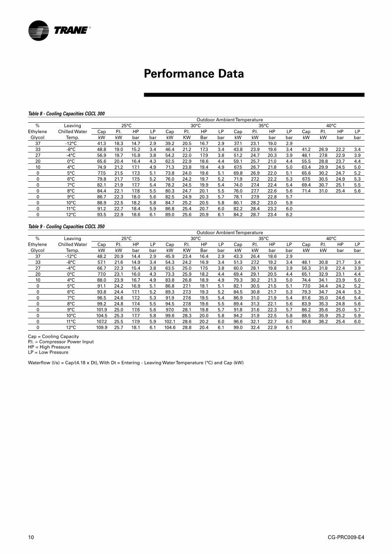
Table 8 - Cooling Capacities CGCL 300Outdoor Ambient Temperature
25°C 30°C 35°C 40°CCap P.I. HP LP Cap P.I. HP LP Cap P.I. HP LP Cap P.I. HP LPkW kW bar bar kW KW Bar bar kW kW bar bar kW kW bar bar
37 -12°C 41.3 18.3 14.7 2.9 39.2 20.5 16.7 2.9 37.1 23.1 19.0 2.933 -8°C 48.8 19.0 15.2 3.4 46.4 21.2 17.3 3.4 43.8 23.9 19.6 3.4 41.2 26.9 22.2 3.427 -4°C 56.9 19.7 15.8 3.8 54.2 22.0 17.9 3.8 51.2 24.7 20.3 3.9 48.1 27.8 22.9 3.920 0°C 65.6 20.4 16.4 4.3 62.5 22.9 18.6 4.4 59.1 25.7 21.0 4.4 55.5 28.8 23.7 4.410 4°C 74.9 21.2 17.1 4.9 71.3 23.8 19.4 4.9 67.5 26.7 21.8 5.0 63.4 29.9 24.5 5.00 5°C 77.5 21.5 17.3 5.1 73.8 24.0 19.6 5.1 69.8 26.9 22.0 5.1 65.6 30.2 24.7 5.20 6°C 79.8 21.7 17.5 5.2 76.0 24.2 19.7 5.2 71.9 27.2 22.2 5.3 67.5 30.5 24.9 5.30 7°C 82.1 21.9 17.7 5.4 78.2 24.5 19.9 5.4 74.0 27.4 22.4 5.4 69.4 30.7 25.1 5.50 8°C 84.4 22.1 17.8 5.5 80.3 24.7 20.1 5.5 76.0 27.7 22.6 5.6 71.4 31.0 25.4 5.60 9°C 86.7 22.3 18.0 5.6 82.5 24.9 20.3 5.7 78.1 27.9 22.8 5.70 10°C 88.9 22.5 18.2 5.8 84.7 25.2 20.5 5.8 80.1 28.2 23.0 5.90 11°C 91.2 22.7 18.4 5.9 86.8 25.4 20.7 6.0 82.2 28.4 23.2 6.00 12°C 93.5 22.9 18.6 6.1 89.0 25.6 20.9 6.1 84.2 28.7 23.4 6.2
Table 9 - Cooling Capacities CGCL 350Outdoor Ambient Temperature
25°C 30°C 35°C 40°CCap P.I. HP LP Cap P.I. HP LP Cap P.I. HP LP Cap P.I. HP LPkW kW bar bar kW KW Bar bar kW kW bar bar kW kW bar bar
37 -12°C 48.2 20.9 14.4 2.9 45.9 23.4 16.4 2.9 43.3 26.4 18.6 2.933 -8°C 57.1 21.6 14.9 3.4 54.3 24.2 16.9 3.4 51.3 27.2 19.2 3.4 48.1 30.8 21.7 3.427 -4°C 66.7 22.3 15.4 3.8 63.5 25.0 17.5 3.8 60.0 28.1 19.8 3.9 56.3 31.8 22.4 3.920 0°C 77.0 23.1 16.0 4.3 73.3 25.9 18.2 4.4 69.4 29.1 20.5 4.4 65.1 32.9 23.1 4.410 4°C 88.0 23.9 16.7 4.9 83.8 26.8 18.9 4.9 79.3 30.2 21.3 5.0 74.4 34.1 23.9 5.00 5°C 91.1 24.2 16.9 5.1 86.8 27.1 19.1 5.1 82.1 30.5 21.5 5.1 77.0 34.4 24.2 5.20 6°C 93.8 24.4 17.1 5.2 89.3 27.3 19.3 5.2 84.5 30.8 21.7 5.3 79.3 34.7 24.4 5.30 7°C 96.5 24.6 17.2 5.3 91.9 27.6 19.5 5.4 86.9 31.0 21.9 5.4 81.6 35.0 24.6 5.40 8°C 99.2 24.8 17.4 5.5 94.5 27.8 19.6 5.5 89.4 31.3 22.1 5.6 83.9 35.3 24.8 5.60 9°C 101.9 25.0 17.6 5.6 97.0 28.1 19.8 5.7 91.8 31.6 22.3 5.7 86.2 35.6 25.0 5.70 10°C 104.5 25.3 17.7 5.8 99.6 28.3 20.0 5.8 94.2 31.9 22.5 5.8 88.5 35.9 25.2 5.90 11°C 107.2 25.5 17.9 5.9 102.1 28.6 20.2 6.0 96.6 32.1 22.7 6.0 90.8 36.2 25.4 6.00 12°C 109.9 25.7 18.1 6.1 104.6 28.8 20.4 6.1 99.0 32.4 22.9 6.1
Cap = Cooling CapacityP.I. = Compressor Power InputHP = High PressureLP = Low Pressure
Waterflow (l/s) = Cap/(4.18 x Dt), With Dt = Entering - Leaving Water Temperature (°C) and Cap (kW)
LeavingChilled Water
Temp.
LeavingChilled Water
Temp.
%EthyleneGlycol
%EthyleneGlycol
Performance Data

CG-PRC009-E4 11
Table 10 - Cooling Capacities CGCL 400Outdoor Ambient Temperature
25°C 30°C 35°C 40°CCap P.I. HP LP Cap P.I. HP LP Cap P.I. HP LP Cap P.I. HP LPkW kW Bar bar kW kW Bar bar kW kW bar bar kW kW bar bar
37 -12°C 56.1 24.3 14.6 3.0 53.2 27.2 16.6 3.0 50.3 30.6 18.9 3.033 -8°C 66.3 25.1 15.1 3.4 63.0 28.1 17.2 3.4 59.5 31.6 19.5 3.4 55.8 35.6 22.1 3.427 -4°C 77.5 26.0 15.7 3.9 73.7 29.1 17.8 3.9 69.7 32.7 20.2 3.9 65.3 36.9 22.8 3.920 0°C 89.5 27.0 16.3 4.4 85.2 30.2 18.5 4.4 80.5 33.9 20.9 4.5 75.5 38.2 23.5 4.510 4°C 102.2 28.1 17.1 5.0 97.2 31.4 19.2 5.0 91.9 35.3 21.7 5.0 86.2 39.6 24.4 5.10 5°C 105.7 28.4 17.2 5.1 100.6 31.8 19.5 5.2 95.1 35.6 21.9 5.2 89.2 40.0 24.6 5.20 6°C 108.8 28.6 17.4 5.3 103.5 32.1 19.7 5.3 97.9 36.0 22.1 5.3 91.8 40.4 24.8 5.40 7°C 111.9 28.9 17.6 5.4 106.5 32.4 19.8 5.5 100.7 36.3 22.3 5.5 94.5 40.7 25.0 5.50 8°C 115.0 29.2 17.8 5.6 109.4 32.7 20.0 5.6 103.5 36.6 22.5 5.6 97.1 41.1 25.2 5.70 9°C 118.1 29.5 18.0 5.7 112.4 33.0 20.2 5.8 106.3 37.0 22.7 5.8 99.7 41.5 25.4 5.80 10°C 121.2 29.7 18.2 5.9 115.3 33.3 20.4 5.9 109.0 37.3 22.9 5.90 11°C 124.3 30.0 18.3 6.0 118.2 33.6 20.6 6.1 111.8 37.6 23.1 6.10 12°C 127.3 30.3 18.5 6.2 121.1 33.9 20.8 6.2 114.5 38.0 23.3 6.2
Table 11 - Cooling Capacities CGCL 450Outdoor Ambient Temperature
25°C 30°C 35°C 40°CCap P.I. HP LP Cap P.I. HP LP Cap P.I. HP LP Cap P.I. HP LPkW kW Bar bar kW kW Bar bar kW kW bar bar kW kW bar bar
37 -12°C 62.2 27.6 14.7 2.9 59.0 30.8 16.8 2.9 55.8 34.6 19.1 2.933 -8°C 73.4 28.5 15.2 3.4 69.8 31.9 17.3 3.4 66.0 35.8 19.6 3.4 62.0 40.3 22.2 3.427 -4°C 85.6 29.6 15.8 3.8 81.5 33.0 18.0 3.8 77.1 37.1 20.3 3.9 72.4 41.7 22.9 3.920 0°C 98.6 30.7 16.5 4.3 93.9 34.3 18.6 4.4 88.8 38.5 21.0 4.4 83.4 43.2 23.7 4.410 4°C 112.3 31.9 17.1 4.9 107.0 35.7 19.4 4.9 101.2 40.0 21.8 4.9 95.0 44.8 24.5 5.00 5°C 116.2 32.3 17.3 5.0 110.6 36.1 19.6 5.1 104.6 40.4 22.0 5.1 98.3 45.2 24.7 5.10 6°C 119.5 32.6 17.5 5.2 113.8 36.4 19.8 5.2 107.6 40.7 22.2 5.2 101.1 45.6 24.9 5.30 7°C 122.9 32.9 17.7 5.3 116.9 36.7 19.9 5.3 110.6 41.1 22.4 5.4 103.9 46.0 25.1 5.40 8°C 126.2 33.2 17.9 5.5 120.1 37.1 20.1 5.5 113.6 41.5 22.6 5.5 106.7 46.4 25.3 5.60 9°C 129.5 33.5 18.0 5.6 123.2 37.4 20.3 5.6 116.6 41.9 22.8 5.70 10°C 132.7 33.8 18.2 5.7 126.3 37.8 20.5 5.8 119.5 42.2 23.0 5.80 11°C 136.0 34.1 18.4 5.9 129.4 38.1 20.7 5.9 122.4 42.6 23.2 5.90 12°C 139.2 34.4 18.6 6.0 132.4 38.4 20.9 6.0 125.3 43.0 23.4 6.1
Cap = Cooling CapacityP.I. = Compressor Power InputHP = High PressureLP = Low Pressure
Waterflow (l/s) = Cap/(4.18 x Dt), With Dt = Entering - Leaving Water Temperature (°C) and Cap (kW)
LeavingChilled Water
Temp.
LeavingChilled Water
Temp.
%EthyleneGlycol
%EthyleneGlycol
Performance Data

12 CG-PRC009-E4
Table 12 - Cooling Capacities CGCL 500Outdoor Ambient Temperature
25°C 30°C 35°C 40°CCap P.I. HP LP Cap P.I. HP LP Cap P.I. HP LP Cap P.I. HP LPkW kW bar bar kW KW bar Bar kW kW bar bar kW kW bar bar
37 -12°C 69.3 30.3 14.6 2.9 65.9 33.9 16.6 2.9 62.3 38.2 18.9 2.933 -8°C 82.1 31.3 15.1 3.4 78.1 35.0 17.2 3.4 73.9 39.4 19.5 3.4 69.4 44.6 22.1 3.427 -4°C 96.3 32.4 15.7 3.8 91.7 36.3 17.8 3.8 86.7 40.9 20.2 3.9 81.4 46.1 22.8 3.920 0°C 111.5 33.6 16.3 4.4 106.2 37.7 18.5 4.4 100.5 42.4 20.9 4.4 94.4 47.8 23.5 4.410 4°C 127.6 34.9 17.0 4.9 121.5 39.1 19.2 4.9 115.0 44.0 21.7 5.0 108.1 49.5 24.4 5.00 5°C 132.1 35.3 17.2 5.1 125.9 39.6 19.5 5.1 119.1 44.5 21.9 5.1 111.9 50.0 24.6 5.20 6°C 135.9 35.6 17.4 5.2 129.5 39.9 19.7 5.2 122.6 44.9 22.1 5.3 115.2 50.5 24.8 5.30 7°C 139.8 35.9 17.6 5.3 133.2 40.3 19.8 5.4 126.1 45.3 22.3 5.4 118.5 50.9 25.0 5.40 8°C 143.6 36.3 17.7 5.5 136.8 40.7 20.0 5.5 129.6 45.7 22.5 5.5 121.7 51.3 25.2 5.60 9°C 147.4 36.6 17.9 5.6 140.5 41.0 20.2 5.7 133.0 46.1 22.7 5.7 125.0 51.8 25.4 5.70 10°C 151.2 36.9 18.1 5.8 144.0 41.4 20.4 5.8 136.4 46.5 22.9 5.80 11°C 154.9 37.3 18.3 5.9 147.6 41.7 20.6 5.9 139.7 46.9 23.1 6.00 12°C 158.6 37.6 18.5 6.0 151.1 42.1 20.8 6.1 143.1 47.3 23.3 6.1
Table 13 - Cooling Capacities CGCL 600Outdoor Ambient Temperature
25°C 30°C 35°C 40°CCap P.I. HP LP Cap P.I. HP LP Cap P.I. HP LP Cap P.I. HP LPkW kW bar bar kW KW bar Bar kW kW bar bar kW kW bar bar
37 -12°C 84.3 37.0 14.8 2.9 80.1 41.4 16.9 2.9 75.8 46.5 19.2 3.033 -8°C 99.8 38.3 15.4 3.4 94.9 42.9 17.5 3.4 89.8 48.1 19.8 3.4 84.5 54.2 22.4 3.427 -4°C 116.9 39.8 16.0 3.9 111.3 44.5 18.1 3.9 105.3 49.9 20.5 3.9 98.9 56.1 23.1 3.920 0°C 135.0 41.3 16.7 4.4 128.6 46.2 18.8 4.4 121.7 51.8 21.2 4.4 114.3 58.2 23.9 4.410 4°C 153.9 43.0 17.4 4.9 146.5 48.1 19.6 5.0 138.7 53.8 22.0 5.0 130.3 60.3 24.7 5.00 5°C 159.1 43.5 17.6 5.1 151.5 48.6 19.8 5.1 143.4 54.4 22.3 5.1 134.7 60.9 24.9 5.20 6°C 163.5 43.9 17.7 5.2 155.7 49.0 20.0 5.3 147.4 54.9 22.4 5.3 138.5 61.4 25.2 5.30 7°C 167.9 44.3 17.9 5.4 159.9 49.5 20.2 5.4 151.3 55.4 22.6 5.4 142.2 62.0 25.3 5.40 8°C 172.3 44.7 18.1 5.5 164.1 49.9 20.3 5.5 155.3 55.9 22.8 5.50 9°C 176.6 45.1 18.2 5.6 168.1 50.4 20.5 5.7 159.1 56.3 23.0 5.70 10°C 180.8 45.5 18.4 5.8 172.1 50.8 20.7 5.8 162.9 56.8 23.2 5.80 11°C 184.9 45.9 18.6 5.9 176.0 51.2 20.9 5.9 166.6 57.3 23.4 5.90 12°C 188.9 46.3 18.8 6.0 179.8 51.7 21.0 6.0 170.2 57.7 23.6 6.1
Cap = Cooling CapacityP.I. = Compressor Power InputHP = High PressureLP = Low Pressure
Waterflow (l/s) = Cap/(4.18 x Dt), With Dt = Entering - Leaving Water Temperature (°C) and Cap (kW)
LeavingChilled Water
Temp.
LeavingChilled Water
Temp.
%EthyleneGlycol
%EthyleneGlycol
Performance Data

CG-PRC009-E4 13
Table 14 - Evaporator Pressure DropWater flow (l/s)
CGCL CGCL CGCL CGCL CGCL CGCL CGCL CGCL
200 250 300 350 400 450 500 600
10 1.155 1.449 1.736 1.912 2.282 2.282 2.500 2.70020 1.631 2.045 2.447 2.809 3.343 3.343 3.561 3.85340 2.301 2.886 3.448 4.129 4.898 4.898 5.074 5.49960 2.815 3.530 4.215 5.172 6.125 6.125 6.241 6.77180 3.248 4.072 4.860 6.068 7.177 7.177 7.228 7.848100 3.629 4.550 5.427 6.868 8.116 8.116 8.100 8.800
Selection with ethylen glycol
When ethylen glycol is added in thechilled water circuit the followingadjustment factors have to be takenin account.
Table 15 - Ethylen glycol adjustment factorsLWTE PCT EG Adjustment factors
(%) Flow rate Pressure drop Power Input Cooling Cap.
12 30 1.11 1.20 1.005 0.985 30 1.11 1.24 1.005 0.984 10 1.02 1.08 - -0 20 1.05 1.19 - --4 27 1.08 1.29 - --8 33 1.10 1.46 - --12 37 1.12 1.62 - -
P.D.(kPa)
Performance Data

14 CG-PRC009-E4
Typical Wiring

CG-PRC009-E4 15
Typical Wiring

16 CG-PRC009-E4
Typical Wiring

CG-PRC009-E4 17
Typical Wiring

18 CG-PRC009-E4
Dimensional Data

CG-PRC009-E4 19
Dimensional Data

20 CG-PRC009-E4
Dimensional Data
CG-PRC009-E4 21
Mechanical Specifications
Cooling only chillers - CGCLGeneral
Units shall be assembled on heavygauge steel mounting/lifting railsand shall be weather proofed. Unitshall include scroll compressors,plate fin condenser coil, brazed plateheat exchangers fans and motors,controls and operating charge ofR407C refrigerant. Operating Rangeshall be between - 5°C and + 40°C incooling as standard.
Casing
Unit casing shall be constructed ofgalvanized steel. Exterior surfacesshall be cleaned, phosphatized andfinished with a weather-resistanttextured polyester powder paint.Units surface shall be tested 500hours in salt spray test. Units shallhave removable end panels whichallow access to all majorcomponents and controls.
Refrigeration System - Single Circuit
CGCL 200, 250, 300, 350, 400 and450 units shall have a singlerefrigeration circuit. Eachrefrigeration circuit has an integralsubcooling circuit. A refrigerationfilter drier, expansion valve andcheck valves shall be provided asstandard. Units shall have both aliquid line and suction gas line withgauge port. The refrigeration circuitis controlled by one thermostaticexpansion valve.CGCL 200, 250, 300, 350, 400 and450 units shall have scrollcompressors with centrifugal oilpump providing positive lubricationto moving parts. Motor shall besuction gas-cooled and shall have avoltage utilization range of plus orminus 10 percent of nameplatevoltage. Temperature and current-sensitive motor overloads shall beincluded for maximum protection.
Refrigeration System - Dual Circuit
CGCL500 and 600 units shall havetwo separate and independentrefrigeration circuits. Eachrefrigeration circuit shall have anintegral subcooling circuit. Arefrigeration filter drier shall beprovided as standard. Units shallhave both a liquid line and suctiongas line with gauge ports. Therefrigeration circuit is controlled byone thermostatic expansion valve.CGCL500 and 600 units shall havescroll compressors with centrifugaloil pump and provide positivelubrication to all moving parts. Motor shall be suction gas-cooledand shall have a voltage utilizationrange of plus or minus 10 percent ofnameplate voltage. Internaltemperature and current-sensitivemotor overloads shall be includedfor maximum protection Therefrigeration circuit is controlled bytwo thermostatic expansion valve.
Condenser Coil
Coils shall be smooth bore 9.52 mmcopper tubes mechanically bondedto configured aluminum plate fin asstandard. Coil shall be factorypressure and leak tested to 30 barair pressure.
Evaporator
Shall be of the stainless steel brazedplates type. Evaporator shall includethermal insulation and anti-freezeprotection. A differential pressostatshall ensure the water flow control.
Condenser Fan And Motor(s)
Forward inclined blades centrifugalfan, statically and dynamicallybalanced, providing a static pressureup to 500 Pa. Flexible duct betweenfan outlet and connection flange.Vertical or horizontal discharge, frontor rear side of the unit. Lifelubricated ball bearing, 1500 RPMmotor, IP44 type with integratedthermal protection. Mechanical belttension system.
Controls
Units shall be completely factorywired with microprocessor basedcontrol and contactor pressure lugsor terminal block for power wiring.Control wiring shall be 230V-voltcontrol circuit which includes fusingand control transformer.Units shall include a fuseddisconnect device.Microprocessor shall control leavingwater temperature, operatingparameters, anti-short cycling, andanti-freeze protection of theevaporator. The liquid crystal displayshall indicate leaving watertemperature and codes of any fault.Dry contacts shall be available forremote signalling of operatingmodes and general faults.
Accessories
Hydraulic Module - Shall provide allcomponents needed for a chilledwater installation network: pump,buffer tank, expansion tank, shut-offand balancing valves, strainerelectrical connections.

22 CG-PRC009-E4
Notes

CG-PRC009-E4 23
Notes

The manufacturer has a policy of continuousproduct improvement, and reserves the rightto alter any details of the products at any timewithout notice.
This publication is a general guide to install,use and properly maintain our products. Theinformation given may be different from thespecification for a particular country or for aspecific order. In this event, please refer toyour nearest office.
Safety recommendationsTo avoid accidents and damage, thefollowing recommendations shouldbe observed during maintenanceand service visits:1. The maximum allowable
pressures for system leak testingon low and high pressure side aregiven in the chapter “Installation”.Always provide a pressureregulator.
2. Disconnect the main supplybefore any servicing on the unit.
3. Service work on the refrigerationsystem and the electrical systemshould be carried out only byqualified and experiencedpersonnel.
Maintenance contractIt is strongly recommended that yousign a maintenance contract withyour local Service Agency. Thiscontract provides regularmaintenance of your installation bya specialist in our equipment.Regular maintenance ensures thatany malfunction is detected andcorrected in good time andminimizes the possibility thatserious damage will occur. Finally,regular maintenance ensures themaximum operating life of yourequipment. We would remind youthat failure to respect theseinstallation and maintenanceinstructions may result in immediatecancellation of the warranty.
TrainingThe equipment described in thismanual is the result of many yearsof research and continuousdevelopment. To assist you inobtaining the best use of it andmaintaining it in perfect operatingcondition over a long period of time,the manufacturer has at yourdisposal a refrigeration and airconditioning service school. Theprincipal aim of this is to giveoperators and technicians a betterknowledge of the equipment theyare using, or that is under theircharge. Emphasis is particularlygiven to the importance of periodicchecks on the unit operatingparameters as well as on preventivemaintenance, which reduces the costof owning the unit by avoidingserious and costly breakdown.
Literature Order Number CG-PRC009-E4
Date 0601
New
Stocking Location Europe
Société Trane – Société Anonyme au capital de 61 005 000 Euros – Siege Social: 1 rue des Amériques –88190 Golbey – France – Siret 306 050 188-00011 – RSC Epinal B 306 050 188Numéro d’identification taxe intracommunautaire: FR 83 3060501888
The Trane CompanyAn American Standard Companywww.trane.com
For more information contactyour local sales office ore-mail us at [email protected]
Since The Trane Company has a policy of continuous product improvement, it reserves the right to changedesign and specifications without notice.
For additional information, contact:Distributor/Installer stamp