air curtain c surface mounted range - … · air curtain c surface mounted range ... thermoscreens...
TRANSCRIPT

T9901007-1-2 CAN-USA-ENG (v9) Page | 1
AIR CURTAIN C SURFACE MOUNTED RANGE
INSTALLATION, OPERATION AND MAINTENANCE INSTRUCTIONS
N. America
English

T9901007-1-2 CAN-USA-ENG (v9) Page | 2
1 CONTENTS ...................................................................................................................................... 2
2 ELECTRICAL SAFETY ..................................................................................................................... 3
3 SPECIFICATIONS ............................................................................................................................ 3
4. INTRODUCTION .............................................................................................................................. 4
5. DELIVERY CONTENTS ................................................................................................................... 5
6. TOOLS REQUIRED .......................................................................................................................... 5
7. INSTALLATION ................................................................................................................................ 6
8. ACCESS FOR ELECTRICAL CONNECTION .................................................................................. 8
9. REMOTE CONTROL INSTALLATION ............................................................................................. 9
10. REMOTE CONTROL SETTINGS ..................................................................................................... 9
11. EXTERNAL CONTROLS ................................................................................................................ 10
12. MULTIPLE AIR CURTAIN SYSTEMS ............................................................................................ 11
13. SYSTEM CONFIGURATION .......................................................................................................... 12
14. FAN SPEED SELECTION .............................................................................................................. 13
15. REMOTE CONTROL OPERATION ................................................................................................ 14
16. COMMISSIONING THE SYSTEM .................................................................................................. 15
17. SIGN OFF ....................................................................................................................................... 15
18. FAULT CONDITIONS ..................................................................................................................... 16
19. SERVICE & MAINTENANCE ......................................................................................................... 17
20. WARRANTY ................................................................................................................................... 18
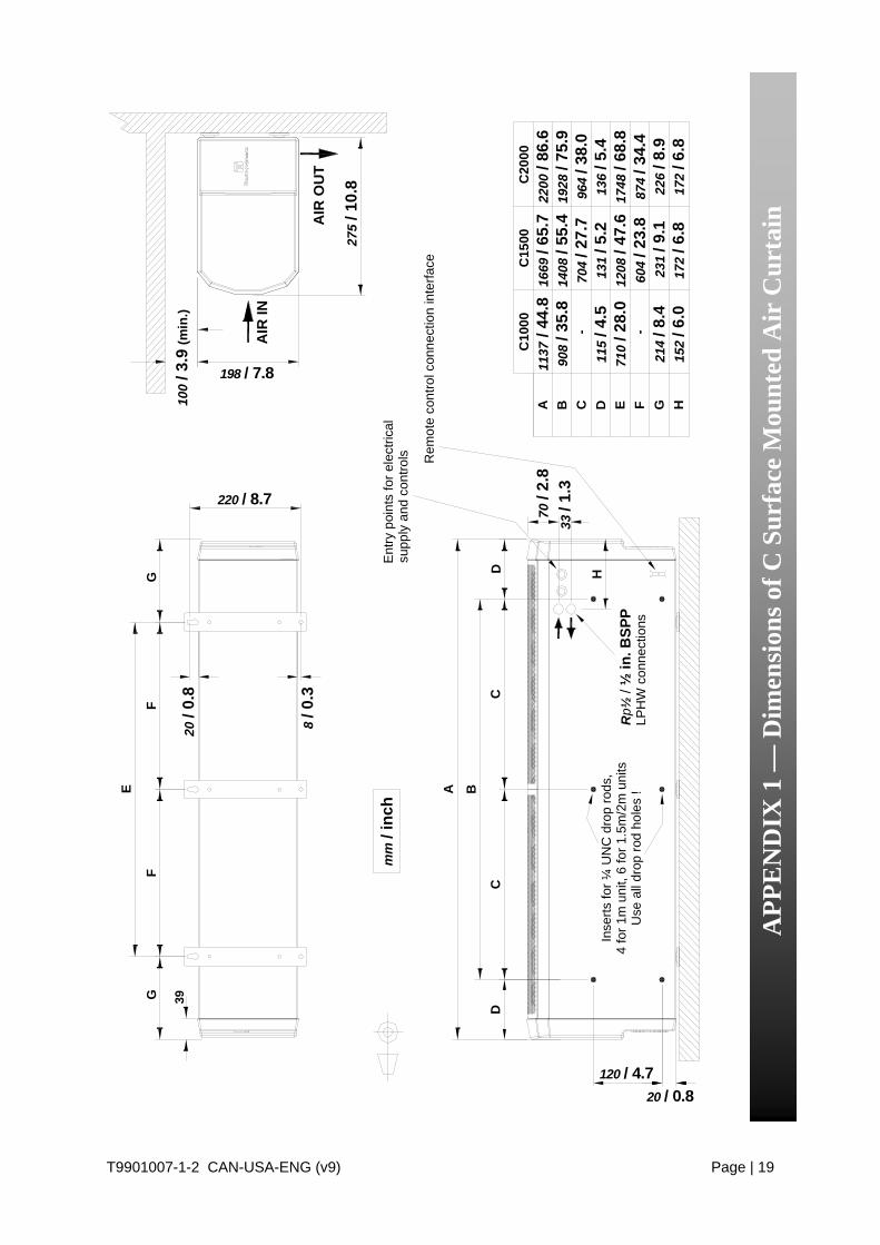
APPENDIX 1 — Dimensions of C Surface Mounted Air Curtain .............................................................. 19
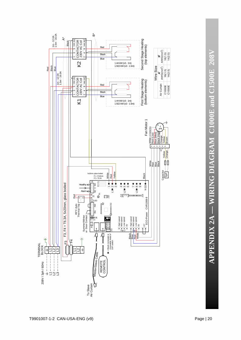
APPENDIX 2A — WIRING DIAGRAM C1000E and C1500E 208V ....................................................... 20
APPENDIX 2B — WIRING DIAGRAM C2000E 208V ............................................................................ 21
APPENDIX 2C — WIRING DIAGRAM C1000E and C1500E 480V or 600V ......................................... 22
APPENDIX 2D — WIRING DIAGRAM C2000E 480V or 600V .............................................................. 23
APPENDIX 2E — WIRING DIAGRAM C1000W, C1500W and C2000W ............................................... 24
APPENDIX 2F — WIRING DIAGRAM C1000A, C1500A and C2000A .................................................. 25
1 CONTENTS
Page

T9901007-1-2 CAN-USA-ENG (v9) Page | 3
Electrical Supply and Wiring to the Air Curtain
All electrical wiring and connections MUST be carried out by a competent qualified electrician in accordance with the latest edition of national and local wiring regulations and/or local statutory regulations. “Danger: Disconnect electrical supply before servicing”
A 1 phase or 3 phase local Disconnect, provided by others in accordance with Electrical Code and Local Electrical Codes, with a contact separation of at least 3mm (1/8in) on all poles, must be fitted in the electrical supply to the air curtain and located in an accessible position adjacent to the unit. Units with dual electrical supplies (see * in Table below) must have a common disconnect to switch off both supplies simultaneously.
The appliance must be connected by cables having an appropriate heat resistant temperature rating.
All supply cables, circuit breakers and other electrical installation equipment must be correctly sized for the air curtain model being installed; see Section 3: Specifications.
Models operating on a 480V or 600V, 3 phase electrical supply - see Section 3: Specifications, Electrical Supply * – also need a separate 208V to 240V electrical supply to operate fan motors and controls.
A 25mm / 1in size cable gland or conduit connector of IP21 rating should be used for the Electrical Supply into the air curtain.
See Wiring Diagrams for connecting electrical supply and control cables to the air curtain. The air curtain must be grounded.
Air Curtain Model No
Electrical Supply (V/ph/Hz)
Rated Electrical
Power Input (kW)
Rated Current per phase (A)
Heat Output [Low/High]
(kW)
Weight
(kg / lbs)
C1000A 208…240/1/60 0.115 0.5 – 15 / 33 C1500A 208…240/1/60 0.161 0.7 – 21 / 46 C2000A 208…240/1/60 0.23 1.0 – 31 / 68 C1000W 208…240/1/60 0.115 0.5 3.0 / 6.0 18 / 39 C1500W 208…240/1/60 0.161 0.7 4.5 / 9.0 26 / 57 C2000W 208…240/1/60 0.23 1.0 6.0 / 12.0 37 / 82 C1000E (208V) 208/3/60 8.755 24.5 4.32 / 8.64 16 / 35 C1500E (208V) 208/3/60 11.693 32.7 5.766 / 11.532 23 / 51 C2000E (208V) 208/3/60 17.51 49.0 ** 8.64 / 17.28 33 / 73
C1000E (480V) 480/3/60 *
+ 208…240/1/60 9
0.115 10.9 0.5
4.5 / 9.0 16 / 35
C1500E (480V) 480/3/60 *
+ 208…240/1/60 12
0.161 14.5 0.7
6.0 / 12.0 23 / 51
C2000E (480V) 480/3/60 *
+ 208…240/1/60 18
0.23 21.7 1.0
9.0 / 18.0 33 / 73
C1000E (600V) 600/3/60 *
+ 208…240/1/60 9
0.115 9.3 0.5
4.5 / 9.0 16 / 35
C1500E (600V) 600/3/60 *
+ 208…240/1/60 12
0.161 12.8 0.7
6.0 / 12.0 23 / 51
C2000E (600V) 600/3/60 *
+ 208…240/1/60 18
0.23 18.6 1.0
9.0 / 18.0 33 / 73
** NOTE. Electric heater circuit current = 47.9 Amps
3 SPECIFICATIONS
2 ELECTRICAL SAFETY
Table 1

T9901007-1-2 CAN-USA-ENG (v9) Page | 4
Established in the 1960s, Thermoscreens is a leading air curtain manufacturer that exports to over 60 countries worldwide. As with all our products, the C range of air curtains is designed with energy efficiency in mind. C models suffixed E, W or A are designed to be surface mounted inside a building and located horizontally over a doorway. They must not be installed on the outside of a building or built into a cabinet or recessed in any way. “Caution: This equipment has been investigated with regard to safety from electrical fire and shock hazard only. The mechanical features have not been investigated and are subject to approval by the inspection authority having jurisdiction.” Please complete the following details for your reference: Date of Purchase Place of Purchase Serial Number Proof of purchase is required to make a claim under warranty.
Thermoscreens Canada Toll Free: 877 445 3739 11 King Street, Unit #3 Tel: 705 797 0012 Barrie, Ontario Fax: 705 797 0013 Canada L4N 6BS Email: [email protected]
http://www.thermoscreens.com
4. INTRODUCTION

T9901007-1-2 CAN-USA-ENG (v9) Page | 5
The following items are supplied in the box at delivery.
The following tools are required for installation:
6. TOOLS REQUIRED
5. DELIVERY CONTENTS
NOTE: If any parts are missing or damaged contact your place of purchase.
C Surface Mounted Air Curtain Ecopower Remote Control
Note: End caps are supplied loose to be fitted during installation
Supplied with 6m / 20ft RJ Control Cable
Outdoor Air Thermostat (Optional – supplied by Installer)
Wall Brackets and M6 Fixing Bolts
Flat blade screwdrivers Phillips head screwdrivers 10mm wrench
Adjustable wrench
Electric drill Ladders
Appropriate lifting equipment
3-port control valve (for water heated units)
3 brackets for C1500 & C2000 units
Fitted in pipework to air curtain by installer
Used for simple weather compensation control
(disables heating on a warmer day)
T9901007-1-2 CAN-USA-ENG (v9) Page | 6
Fig 2
Fig 1
208V - 2.6m / 8ft 6in230V - 3.0m / 9ft 10in
100mm / 4in
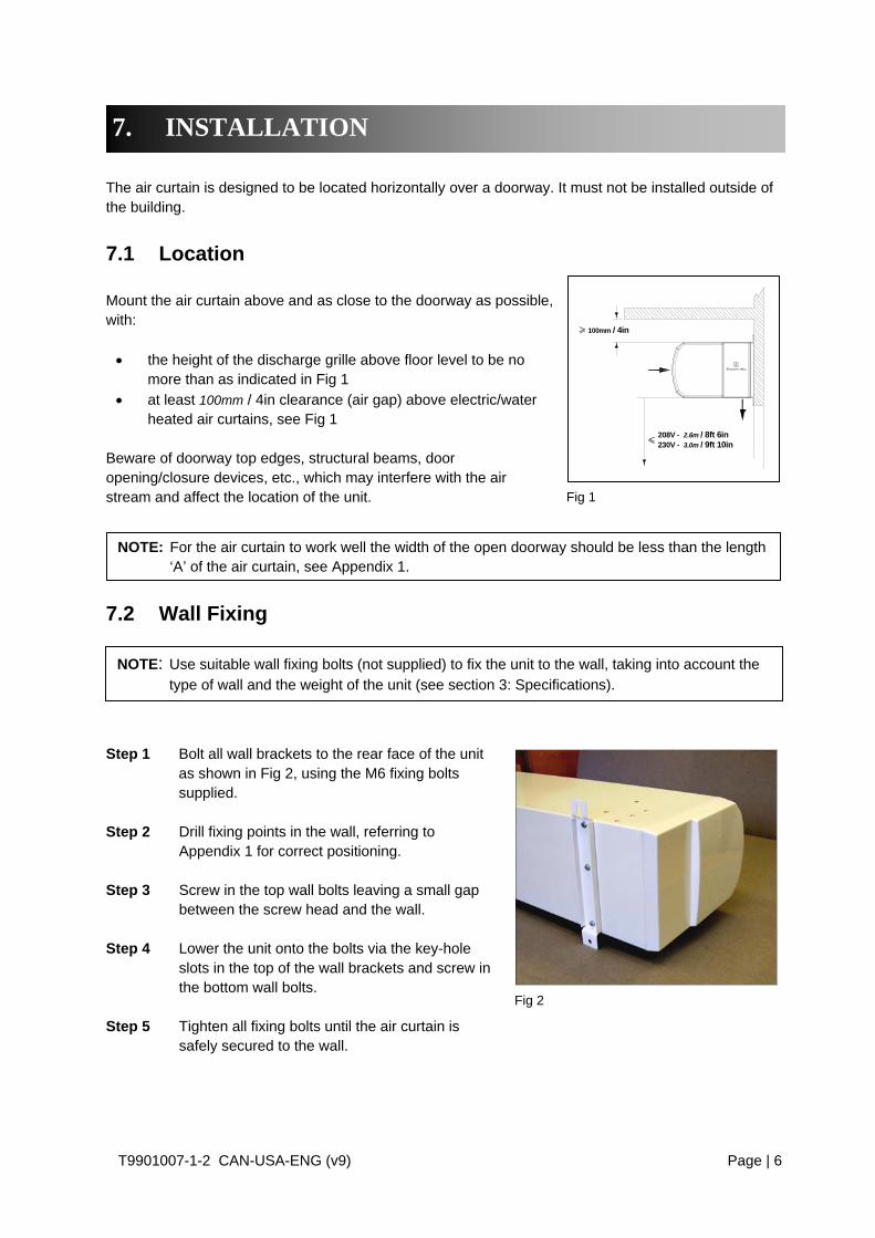
The air curtain is designed to be located horizontally over a doorway. It must not be installed outside of the building.
7.1 Location Mount the air curtain above and as close to the doorway as possible, with: the height of the discharge grille above floor level to be no
more than as indicated in Fig 1 at least 100mm / 4in clearance (air gap) above electric/water
heated air curtains, see Fig 1 Beware of doorway top edges, structural beams, door opening/closure devices, etc., which may interfere with the air stream and affect the location of the unit.
7.2 Wall Fixing Step 1 Bolt all wall brackets to the rear face of the unit
as shown in Fig 2, using the M6 fixing bolts supplied.
Step 2 Drill fixing points in the wall, referring to
Appendix 1 for correct positioning. Step 3 Screw in the top wall bolts leaving a small gap
between the screw head and the wall. Step 4 Lower the unit onto the bolts via the key-hole
slots in the top of the wall brackets and screw in the bottom wall bolts.
Step 5 Tighten all fixing bolts until the air curtain is
safely secured to the wall.
7. INSTALLATION
NOTE: Use suitable wall fixing bolts (not supplied) to fix the unit to the wall, taking into account the
type of wall and the weight of the unit (see section 3: Specifications).
NOTE: For the air curtain to work well the width of the open doorway should be less than the length ‘A’ of the air curtain, see Appendix 1.
T9901007-1-2 CAN-USA-ENG (v9) Page | 7
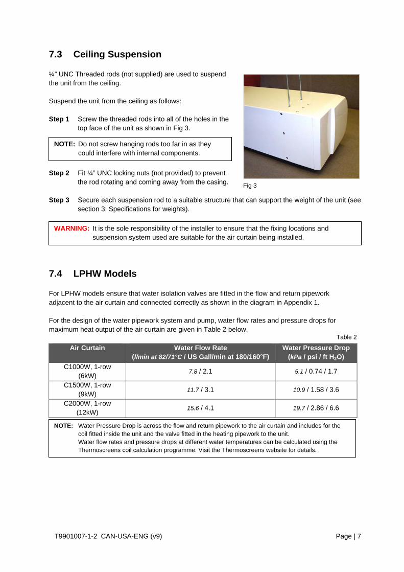
Fig 3
7.3 Ceiling Suspension ¼” UNC Threaded rods (not supplied) are used to suspend the unit from the ceiling. Suspend the unit from the ceiling as follows: Step 1 Screw the threaded rods into all of the holes in the
top face of the unit as shown in Fig 3. Step 2 Fit ¼” UNC locking nuts (not provided) to prevent
the rod rotating and coming away from the casing. Step 3 Secure each suspension rod to a suitable structure that can support the weight of the unit (see
section 3: Specifications for weights).
7.4 LPHW Models For LPHW models ensure that water isolation valves are fitted in the flow and return pipework adjacent to the air curtain and connected correctly as shown in the diagram in Appendix 1. For the design of the water pipework system and pump, water flow rates and pressure drops for maximum heat output of the air curtain are given in Table 2 below.
Air Curtain Water Flow Rate (l/min at 82/71°C / US Gall/min at 180/160°F)
Water Pressure Drop (kPa / psi / ft H2O)
C1000W, 1-row (6kW)
7.8 / 2.1 5.1 / 0.74 / 1.7
C1500W, 1-row (9kW)
11.7 / 3.1 10.9 / 1.58 / 3.6
C2000W, 1-row (12kW)
15.6 / 4.1 19.7 / 2.86 / 6.6
NOTE: Do not screw hanging rods too far in as they could interfere with internal components.
WARNING: It is the sole responsibility of the installer to ensure that the fixing locations and suspension system used are suitable for the air curtain being installed.
NOTE: Water Pressure Drop is across the flow and return pipework to the air curtain and includes for the coil fitted inside the unit and the valve fitted in the heating pipework to the unit. Water flow rates and pressure drops at different water temperatures can be calculated using the Thermoscreens coil calculation programme. Visit the Thermoscreens website for details.
Table 2

T9901007-1-2 CAN-USA-ENG (v9) Page | 8
Fig 4
Fig. 5
The installer must connect the 3-port valve in the heating pipework as shown in Figure 4 below:
22mm pipe
A B
A/B
22mm pipe
22mm pipe
22mm pipe RETURN
FLOW
8.1 How to access terminals To gain access to the air curtain for connection and commissioning, remove air inlet grilles and bottom access panel as explained below. First remove the plastic end caps at each end of the unit, if fitted, by pulling off to the side. 8.1.1 Remove air inlet grilles Using a Philips No 1 screwdriver, remove each grill with its filter. To remove, insert screwdriver into the elongated hole at the bottom corner of the grille (see Fig 5) and turn the screw one quarter of a turn anticlockwise. 8.1.2 Remove bottom access panel Unfasten the securing screw at each end (see 1, Fig 6) and, if applicable, two screws in the centre (C1500 and C2000 units only). To remove, slide the access panel (see 2, Fig 6) out forwards.
8. ACCESS FOR ELECTRICAL CONNECTION
NOTE: All air curtain panels are protected in a plastic film. When access panels are removed this film can be removed.
wire valve to pcb inside air curtain
1 Fig. 6 2

T9901007-1-2 CAN-USA-ENG (v9) Page | 9
Mount the Ecopower remote control in a convenient position directly to the wall or onto a switch box.
9.1 Wall mounting Step 1 Using a screwdriver undo the screw on the top of the remote control
case and pull the back case away (see Fig 7). Step 2 Feed one end of the RJ control cable through the back case, secure it,
then screw the back case to the wall using suitable fixings (not supplied).
Step 3 Connect the RJ plug to the RJ socket on the PCB in the remote control. Step 4 Refit the front case.
9.2 Switch box mounting Step 1 Using a screwdriver undo the screw on the top of the remote control case and pull the back
case away (see Fig 7). Step 2 Feed one end of the RJ control cable through the switch box, feed and
secure the RJ control cable through the back case and secure back case to switch box using 2 mounting screws (not supplied) (see Fig 8).
Step 3 Connect the RJ plug to the RJ socket on the PCB in the remote
control. Step 4 Refit the front case.
On the back of the PCB inside the Ecopower Remote Control you will find four DIP switches that provide the following optional features, see Table 3:
DIP Feature Explanation Default Notes 1 Reset on power-up On restoring power after an
electrical interruption all Remote Control settings are retained
ON WARNING! – Fans start on their own after power is restored
2 Stop fan on cold Fans are switched off when heating level is achieved (AUTO mode only)
OFF
3 Never blow cold Air curtain always heats in AUTO mode
OFF Will not go to ambient mode
4 Room air temperature control
Enables the room air sensor in the Remote Control
OFF Disables all other temperature sensors
10. REMOTE CONTROL SETTINGS
9. REMOTE CONTROL INSTALLATION
NOTE: For optional remote control settings see Section 10.
Fig 7
Fig 8
23/8in
Table 3

T9901007-1-2 CAN-USA-ENG (v9) Page | 10
11.1 Remote switch contacts IN0, IN1 Terminals IN0 and IN1 on the Ecopower PCB inside the air curtain can be used to provide different control strategies using remote volt-free contacts (see Fig 9). This could be to provide remote On/Off from a timer or BMS Digital/Output contact, to work with a door switch or for simple weather compensation control to disable heating when outdoor air temperatures become warmer. Table 4 describes the different functions:
Function IN0 Notes
Remote On/Off
(INHIBIT)
Unit operates normally in MANUAL Mode or AUTO Mode from the Remote Control
Unit switches off after 15s, with fan run-on at Medium fan speed if DIP 2 = OFF
Use the Remote Control to set up unit and then hide it away if required. * On/Off is then done via IN0 using a remote volt-free contact.
Function IN1 DIP 4 IN0 Notes
Door
Switch Control
After 30s the heating is disabled and the fan goes to low speed
Unit operates normally in MANUAL Mode or AUTO Mode from the Remote Control
ON
Door Open:- Normal Control Door Closed:- Heating Off Low Fan Speed
Summer
Winter
Unit operates normally in MANUAL Mode or AUTO Mode from the Remote Control
COLD DAY
Heating is disabled straight away, Fan speeds operate normally from the Remote Control
WARM DAY
OFF
Simple weather compensation control using an outdoor air thermostat with volt free contacts (see Section 11.3)
11. EXTERNAL CONTROLS
Fig 9
Table 4
WARNING: Do not apply any voltage to terminals IN0 and IN1 as this will damage the Ecopower PCB inside the air curtain.
NOTE: Wire volt-free, remote switch contacts to 2-way screw terminals IN0 and IN1 using 2-core cable.
* NOTE: The Ecopower Remote Control must stay plugged-in for the air curtain to keep working. An optional plug-in EEPROM is available from Thermoscreens so the Remote Control can be un-plugged and the air curtain stay working. Visit the Thermoscreens website for details.
T9901007-1-2 CAN-USA-ENG (v9) Page | 11
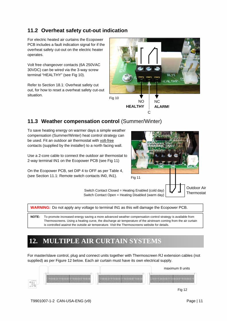
11.2 Overheat safety cut-out indication
For electric heated air curtains the Ecopower PCB includes a fault indication signal for if the overheat safety cut-out on the electric heater operates. Volt free changeover contacts (6A 250VAC 30VDC) can be wired via the 3-way screw terminal “HEALTHY” (see Fig 10). Refer to Section 18.1: Overheat safety cut out, for how to reset a overheat safety cut-out situation.
11.3 Weather compensation control (Summer/Winter)
To save heating energy on warmer days a simple weather compensation (Summer/Winter) heat control strategy can be used. Fit an outdoor air thermostat with volt-free contacts (supplied by the installer) to a north facing wall. Use a 2-core cable to connect the outdoor air thermostat to 2-way terminal IN1 on the Ecopower PCB (see Fig 11) On the Ecopower PCB, set DIP 4 to OFF as per Table 4, (see Section 11.1: Remote switch contacts IN0, IN1).
For master/slave control, plug and connect units together with Thermoscreen RJ extension cables (not supplied) as per Figure 12 below. Each air curtain must have its own electrical supply.
12. MULTIPLE AIR CURTAIN SYSTEMS
C
NC ALARM!
NO HEALTHY
Fig 10
Fig 12
maximum 8 units
WARNING: Do not apply any voltage to terminal IN1 as this will damage the Ecopower PCB.
NOTE: To promote increased energy saving a more advanced weather compensation control strategy is available from Thermoscreens. Using a heating curve, the discharge air temperature of the airstream coming from the air curtain is controlled against the outside air temperature. Visit the Thermoscreens website for details.
Fig 11
Switch Contact Closed = Heating Enabled (cold day) Switch Contact Open = Heating Disabled (warm day)
Outdoor Air Thermostat
T9901007-1-2 CAN-USA-ENG (v9) Page | 12
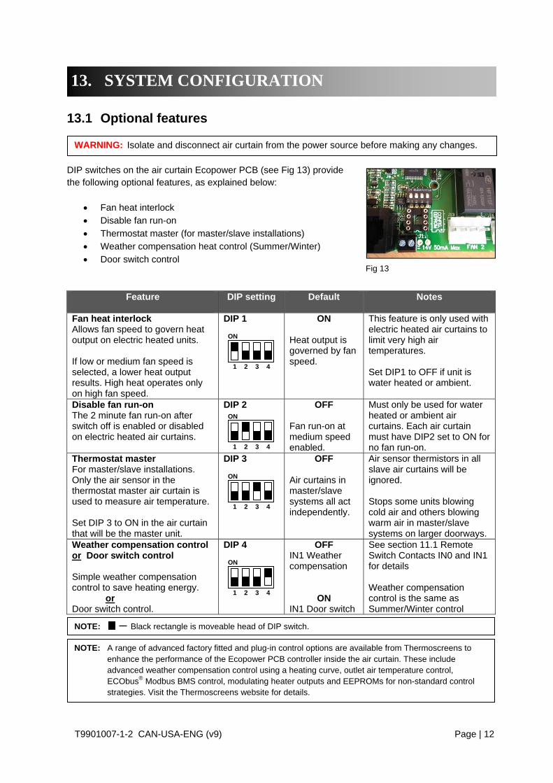
13.1 Optional features DIP switches on the air curtain Ecopower PCB (see Fig 13) provide the following optional features, as explained below:
Fan heat interlock Disable fan run-on Thermostat master (for master/slave installations) Weather compensation heat control (Summer/Winter) Door switch control
Feature
DIP setting Default Notes
Fan heat interlock Allows fan speed to govern heat output on electric heated units. If low or medium fan speed is selected, a lower heat output results. High heat operates only on high fan speed.
DIP 1
ON Heat output is governed by fan speed.
This feature is only used with electric heated air curtains to limit very high air temperatures. Set DIP1 to OFF if unit is water heated or ambient.
Disable fan run-on The 2 minute fan run-on after switch off is enabled or disabled on electric heated air curtains.
DIP 2
OFF Fan run-on at medium speed enabled.
Must only be used for water heated or ambient air curtains. Each air curtain must have DIP2 set to ON for no fan run-on.
Thermostat master For master/slave installations. Only the air sensor in the thermostat master air curtain is used to measure air temperature. Set DIP 3 to ON in the air curtain that will be the master unit.
DIP 3
OFF Air curtains in master/slave systems all act independently.
Air sensor thermistors in all slave air curtains will be ignored. Stops some units blowing cold air and others blowing warm air in master/slave systems on larger doorways.
Weather compensation control or Door switch control Simple weather compensation control to save heating energy. or Door switch control.
DIP 4
OFF IN1 Weather compensation
ON IN1 Door switch
See section 11.1 Remote Switch Contacts IN0 and IN1 for details Weather compensation control is the same as Summer/Winter control
13. SYSTEM CONFIGURATION
Fig 13
WARNING: Isolate and disconnect air curtain from the power source before making any changes.
ON
1 2 3 4
ON
1 2 3 4
ON
1 2 3 4
NOTE: A range of advanced factory fitted and plug-in control options are available from Thermoscreens to enhance the performance of the Ecopower PCB controller inside the air curtain. These include advanced weather compensation control using a heating curve, outlet air temperature control, ECObus® Modbus BMS control, modulating heater outputs and EEPROMs for non-standard control strategies. Visit the Thermoscreens website for details.
NOTE: Black rectangle is moveable head of DIP switch.
ON
1 2 3 4

T9901007-1-2 CAN-USA-ENG (v9) Page | 13
Factory settings for the 3 fan speeds are shown in Tables 5 or 6 below:
Fan running on 208V (refer to wiring diagrams in Appendix 2)
Fan Speed
Maximum air velocity at outlet grille (m/s / ft/min)
Maximum air curtain mounting height
(m / ft)
Sound Pressure Level of air
curtain [dB(A) at 3m /10ft]
Air Volume Flow Rate (m3/h / cfm)
HIGH (black wire)
8.5 / 1675 2.6 / 8ft 6in
C1000 - 54 C1500 - 54 C2000 - 55
1125 / 660 1620 / 955
2250 / 1325 MEDIUM
(blue wire)
–
– C1000 - 50 C1500 - 50 C2000 - 51
1115 / 655 1600 / 940
2225 / 1310 LOW
(red wire)
–
– C1000 - 45 C1500 - 45 C2000 - 46
975 / 575 1405 / 825
1950 / 1150
Fan running on 230V (refer to wiring diagrams in Appendix 2)
Fan Speed
Maximum air velocity at outlet grille (m/s / ft/min)
Maximum air curtain mounting height
(m / ft)
Sound Pressure Level of air
curtain [dB(A) at 3m /10ft]
Air Volume Flow Rate (m3/h / cfm)
HIGH (black wire)
9.0 / 1770 3.0 / 9ft 10in
C1000 - 55 C1500 - 55 C2000 - 56
1250 / 740 1800 / 1060 2500 / 1470
MEDIUM (blue wire)
–
–
C1000 - 53 C1500 - 53 C2000 - 54
1140 / 670 1640 / 965
2275 / 1340 LOW
(red wire)
–
– C1000 - 50 C1500 - 49 C2000 - 50
1025 / 605 1475 / 870
2050 / 1205
Sound pressure levels dB(A) at 3m/10ft distance are for a single air curtain mounted at its maximum mounting height, operating in a room with average acoustic characteristics as defined in CIBSE Guide B5 (reverberation time 0.7s at 1kHz) and a room size equivalent to 8 air changes per hour (ac/h). Care needs to be taken when selecting air curtains for an installation as noise levels can be several dB higher if the mounting height is reduced, if the room is more ‘live’ (i.e. hard surfaces, no furnishings or absorbent materials), if the room is smaller than 8 ac/h equivalent or a combination of these factors. Noise levels will also increase if more than one air curtain is installed at the same doorway (e.g. +3dB(A) for 2 equal point sources: direct field).
14. FAN SPEED SELECTION
Table 5
Table 6
T9901007-1-2 CAN-USA-ENG (v9) Page | 14
2
1
3
4
5
6
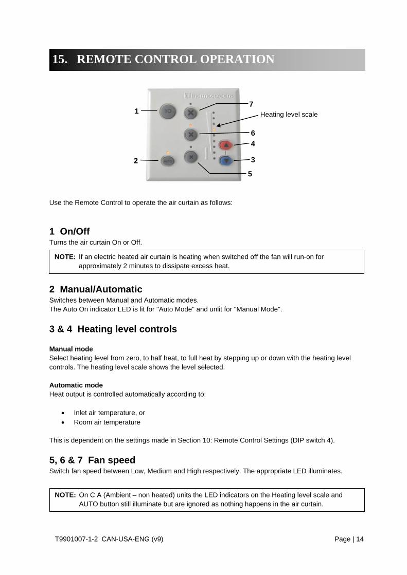
7Heating level scale
Use the Remote Control to operate the air curtain as follows:
1 On/Off Turns the air curtain On or Off.
2 Manual/Automatic Switches between Manual and Automatic modes. The Auto On indicator LED is lit for "Auto Mode" and unlit for "Manual Mode".
3 & 4 Heating level controls Manual mode Select heating level from zero, to half heat, to full heat by stepping up or down with the heating level controls. The heating level scale shows the level selected. Automatic mode Heat output is controlled automatically according to:
Inlet air temperature, or Room air temperature
This is dependent on the settings made in Section 10: Remote Control Settings (DIP switch 4).
5, 6 & 7 Fan speed Switch fan speed between Low, Medium and High respectively. The appropriate LED illuminates.
15. REMOTE CONTROL OPERATION
NOTE: If an electric heated air curtain is heating when switched off the fan will run-on for approximately 2 minutes to dissipate excess heat.
NOTE: On C A (Ambient – non heated) units the LED indicators on the Heating level scale and AUTO button still illuminate but are ignored as nothing happens in the air curtain.
T9901007-1-2 CAN-USA-ENG (v9) Page | 15
16.1 Verify system operation To commission the system, verify the following conditions are met:
All fans are working.
Fans operate at Low, Medium and High speeds.
There is no excessive mechanical noise coming from the fans.
When heating is selected, the air stream from the discharge grille warms up across the whole length of the air curtain.
When set to manual with fans set to high speed, heating increases as higher heat is selected.
Warm air reaches across the doorway with door open or closed.
Ecopower Remote Control operates correctly in both manual and auto modes.
16.2 Instruct customer and hand over Before leaving site, hand over the installation to the customer/end user or their representative. Explain that any person operating the air curtain must be given supervision and instruction by the person responsible for their safety, concerning the safe use of the unit and to understand any hazards involved. Children and those with reduced physical, sensory or mental capabilities should not operate the air curtain. Recommend that the doorway should be closed whenever possible but that during times of high pedestrian use it will become an ‘open doorway’. The air curtain then serves an essential purpose by saving energy and providing comfort to occupants. Explain that the inlet grilles and air filters (if fitted) must be cleaned regularly and the unit serviced at schedule intervals – see section 19: Service & Maintenance.
Complete the following once commissioning is completed: Installer signature
Customer signature
Installer name
Customer name
Installer company
Customer company
Date
Date
17. SIGN OFF
16. COMMISSIONING THE SYSTEM
NOTE: Leave these instructions with the customer/end user or their representative!!

T9901007-1-2 CAN-USA-ENG (v9) Page | 16
18.1 Overheat Safety cut-out An overheat fault in electric heated units may cause the overheat safety cut-out(s) to operate. This is indicated by flashing LEDs on the Remote Control and a red status LED on the Ecopower PCB inside the air curtain. Before resetting ensure there is adequate air flow from the air curtain and the unit has been commissioned as per section 16. To reset a overheat safety cut-out: Step 1 Switch off the electrical supply to the air curtain. Step 2 Allow time for the air curtain to cool down, typically 10 minutes. Step 3 Switch on the electrical supply to the air curtain. Step 4 Press the Auto button on the Ecopower remote control 4 times. Air curtain heaters will then operate and after 30 seconds the LEDs on the remote control will stop flashing and the status LED on the Ecopower PCB in the air curtain will flash green.
18.2 Fuses In the event of an electrical fault internal electrical fuses may operate. There are two 6.3A(T) internal fuses located in two DIN-rail fused terminals inside the air curtain There are also two internal fuses located on the Ecopower PCB inside the air curtain:
Fuse 6.3A(T) supplies the fan motors within the air curtain Fuse 100mA(F) controls the circuitry of the Ecopower PCB
18.3 Ecopower PCB status indication There is a status LED on the Ecopower PCB inside the air curtain (See LED shown on Wiring Diagrams in the Appendix). This indicates the status of the Ecopower Control system as follows:
1. LED flashing green – operation normal 2. LED flashing red – low supply voltage, remote control not plugged in or RJ cable fault 3. LED permanently red – overheat safety cut-out(s) open circuit from an overheat situation.
Indicators on Ecopower Remote Control also flash! (see Section 18: Fault Conditions for how to reset)
18. FAULT CONDITIONS

T9901007-1-2 CAN-USA-ENG (v9) Page | 17
19.1 Every week Turn off the air curtain to prevent entry of dust then clean the face of the air inlet grilles and air filters inside the grilles using a vacuum cleaner with an extension tube and brush.
19.2 Every 3 months Clean and inspect the inside of the air curtain as follows: Step 1 Remove plastic end caps at each end of the unit by pulling off to the side. Step 2 Use a Philips No.1 screwdriver to remove air inlet grilles by releasing the fasteners at the
bottom corners of each air inlet grille. See Fig 5, Section 8.1.1. Step 3 Clean and remove any build-up of dust and dirt within the air-curtain (inlet/outlet grilles,
electric heaters, fan impellers, housings and motors) using a vacuum cleaner and soft brush.
Step 4 Check within the unit to ensure all electrical connections and crimped terminals are tight
and that all cables are in good condition. Refit air inlet grilles after servicing. Reconnect electrical supply and test to ensure correct operation (see Section 16: Commissioning).
19. SERVICE & MAINTENANCE
NOTE: Weekly maintenance can be carried out by the Cleaner or Janitor from floor level.
NOTE: Build-up of dirt on fan impellers can cause vibration, noise and excessive wear on the motor bearings.
WARNING: Before servicing, isolate and disconnect the air curtain from the electrical power.
WARNING: The following servicing and maintenance must be carried out by a competent electrician or a Thermoscreens appointed technician.
WARNING: Failure to adequately maintain the unit and provide a suitable cleaning schedule will result in a loss of performance and reduced life expectancy of the air-curtain and possible overheating and fire risk with electric heated units.

T9901007-1-2 CAN-USA-ENG (v9) Page | 18
All units are covered by a two year warranty. Failure to adequately maintain the unit may void the warranty. If any problems are encountered, please contact your installer/supplier. Failing this please contact Thermoscreens Canada. Care has been taken in compiling these instructions to ensure they are correct. Thermoscreens Canada disclaims all liability for damage resulting from any inaccuracies and/or deficiencies in this documentation. Thermoscreens Canada retain the right to change the specifications stated in these instructions. Thermoscreens Canada Toll Free: 877 445 3739 11 King Street, Unit #3 Tel: 705 797 0012 Barrie, Ontario Fax: 705 797 0013 Canada L4N 6BS Email: [email protected]
20. WARRANTY
T9901007-1-2 CAN-USA-ENG (v9) Page | 19
1137
/ 4
4.8
C10
00C
1500
C20
00
A
-
Inse
rts
for
¼ U
NC
dro
p r
ods,
4 fo
r 1m
un
it, 6
for
1.5m
/2m
uni
tsU
se a
ll dr
op r
od h
oles
!E
FF
220 / 8.7
20 /
0.8
100
/ 3
.9 (
min
.)
AIR
IN
AIR
OU
T
275
/ 10
.8
A B
DD
C
Rem
ote
con
tro
l con
nec
tion
inte
rfac
e
Ent
ry p
oin
ts fo
r el
ectr
ical
su
pply
and
con
trol
s
Rp
½ /
½ in
. B
SP
PL
PH
W c
onn
ectio
ns
GG
mm
/ in
ch
8 /
0.3
198 / 7.8
120 / 4.7
20 / 0.8
B C D E F G
1669
/ 6
5.7
2200
/ 86
.690
8 /
35.
814
08 /
55.4
1928
/ 7
5.9
704
/ 2
7.7
964
/ 38
.011
5 /
4.5
131
/ 5.
213
6 /
5.4
214
/ 8
.422
6 /
8.9
231
/ 9.
1
C
710
/ 2
8.0
1208
/ 4
7.6
1748
/ 6
8.8
-60
4 /
23.
887
4 /
34.
4
H15
2 /
6.0
172
/ 6.
817
2 /
6.8
H
33 /
1.3
70 /
2.8
39
AP
PE
ND
IX 1
— D
imen
sion
s of
C S
urf
ace
Mou
nte
d A
ir C
urt
ain
T9901007-1-2 CAN-USA-ENG (v9) Page | 20
0 1 2 3 4 5
1~
Whi
te (
CO
MM
ON
)
Red
(Lo
w)
Blu
e (M
ed)
Bla
ck (
Hig
h)
Ora
nge
Ye
llow
TE
RM
INA
LB
LOC
K
L1 L2 L3
L1 L2 L3
208
V /
3p
h /
60H
z
Bla
ckB
lue
Re
dW
hite
Whi
te
Red
Ye
llow
Bla
ckF
an M
oto
r 1
CO
NT
AC
TO
R23
0V A
C C
oilA1
A2
13N
O
14N
O
1 2
3 4
5 6
K1
CO
NT
AC
TO
R2
30
V A
C C
oilA1
A2
13N
O
14N
O
1 2
3 4
5 6
K2
Red
Bla
ck
Blu
e
A*
Whi
teR
edB
lue
Bla
ck
Bro
wn
Ye
llow
Ora
nge
Cap
acito
r
B*
F3 F4
Bla
ck
1.44 kW (x3 - 1m)1.922 kW (x3 - 1.5m)
Blue
Black
Red
Blue
Black
Red1m
- 1
2.0
A1
.5m
- 1
6.0
A
F1 = F100mAF2 = T6.3A
Firs
t Sta
ge
Hea
ting
(bot
tom
ele
me
nts)
Sec
ond
Sta
ge H
eatin
g(t
op e
lem
ents
)
2*
2*
Red
85°
C A
uto
Th
erm
al T
rip
1 2 3 4
ON
RE
MO
TE
CO
NT
RO
L
To
Sla
veA
ir C
urt
ain
Mas
ter/
Sla
ve C
able
IN1
IN0
LED
J2N
CC
NO
J1
Hig
h s
peed
Med
spe
edL
ow s
peed
0V Hig
h s
peed
Med
spe
edL
ow s
peed
0V
Fan 2 Fan 1
J17 E
CO
-Po
we
r
CV
R1
008-
910987654321
L3
N
L2L1
J10 J16
J12
J5
J6
J11
R 0 -10V
J14T
h
EEP
RO
M
F2
F1
J9
Alarm
Healthy
Bla
ck r
ect
ang
le is
mo
vea
ble
hea
d of
DIP
sw
itch
Su
mm
er/
Win
ter
or
Doo
r C
ont
act
1.44 kW (x3 - 1m)1.922 kW (x3 - 1.5m)
1m
- 1
2.0
A1
.5m
- 1
6.0
A
L2L1
F3,
F4
= T
6.3
A,
5x2
0mm
, gla
ss b
odie
d
5x20mm, glass bodied
3µ
F
AP
PE
ND
IX 2
A —
WIR
ING
DIA
GR
AM
C10
00E
an
d C
1500
E 2
08V

T9901007-1-2 CAN-USA-ENG (v9) Page | 21
2*
2*
0 1 2 3 4 5
1~
Wh
ite (
CO
MM
ON
)
Re
d (
Low
)B
lue
(Me
d)
Bla
ck (
Hig
h)O
ran
geY
ello
w
TE
RM
INA
LB
LOC
K
L1 L2 L3
L1 L2 L3
208V
/ 3
ph /
60H
z
L2L1
Bla
ckB
lue
Re
dW
hite
Bla
ckB
lue
Re
dW
hite
Whi
te
Re
d
Ye
llow
Fan
Mot
or 1
Fan
Mot
or 2
CO
NT
AC
TO
R2
30V
AC
Coi
lA1
A2
13N
O
14N
O
1 2
3 4
5 6
K1
CO
NT
AC
TO
R2
30V
AC
Coi
lA1
A2
13N
O
14N
O
1 2
3 4
5 6
K2
Re
d
Bla
ck
Blu
e
A*
23.9
5A
23.9
5A
Fir
st S
tage
Hea
ting
(bot
tom
ele
men
ts)
Se
con
d S
tag
e H
eatin
g(t
op e
lem
ents
)
Wh
iteR
edB
lue
Bla
ck
Bro
wn
Ye
llow
Ora
ng
e
Ca
pa
cito
r
0 1 2 3 4 5
1~
Whi
te (
CO
MM
ON
)
Re
d (
Low
)B
lue
(M
ed)
Bla
ck (
Hig
h)
Yel
low
Whi
teR
ed
Blu
eB
lack
Yel
low
Ora
nge
Ca
pa
cito
r
B*
F3 F4
Bla
ck
Blue
Black
Red
Blue
Black
Red
Bla
ck
F1 = F100mAF2 = T6.3A
Bro
wn
Ora
nge
1 2 3 4
ON
RE
MO
TE
CO
NT
RO
L
To
Sla
veA
ir C
urta
in
Mas
ter/
Sla
ve C
able
IN1
IN0
LED
J2N
CC
NO
J1
Hig
h sp
eed
Me
d sp
eed
Low
spe
ed
0V
Hig
h sp
eed
Me
d sp
eed
Low
spe
ed
0V
Fan 2 Fan 1
J17 E
CO
-Po
wer
C
VR
100
8-9
10987654321
L3
N
L2L1
J10 J16
J12
J5
J6
J11
R 0 -10V
J14T
h
EEPR
OM
F2
F1
J9
Alarm
Healthy
Re
d8
5°C
Au
to
Th
erm
al T
rip(x
2)
Bla
ck r
ecta
ngle
is
mo
veab
le h
ea
d of
D
IP s
witc
h
Su
mm
er/
Win
ter
or
Doo
r C
on
tact
3µ
F
3µ
F
1.44 kW (x3)
1.44 kW (x3) 1.44 kW (x3)
1.44 kW (x3)
F3,
F4
= T
6.3A
, 5x
20m
m, g
lass
bod
ied
5x20mm, glass bodied
AP
PE
ND
IX 2
B —
WIR
ING
DIA
GR
AM
C20
00E
208
V

T9901007-1-2 CAN-USA-ENG (v9) Page | 22
0 1 2 3 4 5
1~
Whi
te (C
OM
MO
N)
Red
(Lo
w)
Blu
e (
Med
)B
lack
(H
igh
)O
ran
geY
ello
w
TE
RM
INA
LB
LO
CK
L1 L2 L3
L1 L2 L3
F3
F4
208
V to
240
V1
ph
/ 6
0Hz
L2L1
Bla
ckB
lue
Red
Whi
te
Whi
te
Red
Yel
low
Bla
ckF
an M
otor
1
CO
NT
AC
TO
R2
30V
AC
Coi
lA1
A2
13N
O
14N
O
1 2
3 4
5 6
K1
CO
NT
AC
TO
R2
30
V A
C C
oilA1
A2
13N
O
14N
O
1 2
3 4
5 6
K2
Red
Bla
ck
Blu
e
Bla
ckA
*
1.5
m -
7.2
A a
t 48
0V1
.5m
- 5
.8A
at 6
00V
Firs
t Sta
ge
Hea
ting
(bot
tom
ele
me
nts)
Sec
ond
Sta
ge H
eatin
g(t
op e
lem
ents
)
F3,
F4
= T
6.3A
, 5x
20m
m, g
lass
bod
ied
WA
RN
ING
!U
NIT
RE
QU
IRE
S M
OR
E T
HA
N O
NE
SO
UR
CE
OF
EL
EC
TR
ICA
L P
OW
ER
Disconnecting meansintegral to the unit for bothsources of electrical power
is required !
Whi
teR
edB
lue
Bla
ck
Bro
wn
Ye
llow
Ora
nge
Cap
aci
tor
Blue
Black
Red
B*
2*
2*
1.5 kW (x3 - 1m)2 kW (x3 - 1.5m)
1.5 kW (x3 - 1m)2 kW (x3 - 1.5m)
Blue
Black
Red1m
- 5
.4A
at 4
80V
1m
- 4
.3A
at 6
00V
F1 = F100mAF2 = T6.3A
48
0V
/ 3
ph
/ 60
Hz
or
60
0V
/ 3
ph
/ 60H
z
Red
85°
C A
uto
Th
erm
al T
rip
1 2 3 4
ON
RE
MO
TE
CO
NT
RO
L
To
Sla
veA
ir C
urta
inM
aste
r/S
lave
Ca
ble
IN1
IN0
LED
J2N
CC
NO
J1
Hig
h sp
eed
Me
d sp
eed
Lo
w s
peed
0V Hig
h sp
eed
Me
d sp
eed
Lo
w s
peed
0V
Fan 2 Fan 1
J17 E
CO
-Pow
er
CV
R10
08
-910987654321
L3
N
L2L1
J10 J16
J12
J5
J6
J11
R 0 -10V
J14T
h
EEPR
OM
F2
F1
J9
Alarm
Healthy
Bla
ck r
ect
ang
le is
mo
veab
le h
ead
of
DIP
sw
itch
Su
mm
er/
Win
ter
or
Doo
r C
ont
act
L1 L2
5x20mm, glass bodied3µ
F
AP
PE
ND
IX 2
C —
WIR
ING
DIA
GR
AM
C10
00E
an
d C
1500
E 4
80V
or
600V

T9901007-1-2 CAN-USA-ENG (v9) Page | 23
2*
2*
0 1 2 3 4 5
1~
Whi
te (
CO
MM
ON
)
Red
(Lo
w)
Blu
e (
Med
)B
lack
(H
igh)
Ora
nge
Yel
low
TE
RM
INA
LB
LOC
K
L1
L2
L3
L1
L2
L3
F3
F4
Bla
ckB
lue
Red
Whi
te
Bla
ckB
lue
Red
Whi
te
Whi
te
Red
Yel
low
Bla
ckF
an M
otor
1
Fa
n M
oto
r 2
CO
NT
AC
TO
R23
0V
AC
Coi
lA1
A2
13N
O
14N
O
1 2
3 4
5 6
K1
CO
NT
AC
TO
R2
30V
AC
Coi
lA1
A2
13N
O
14N
O
1 2
3 4
5 6
K2
Red
Bla
ck
Blu
e
Bla
ck
A*
10
.8A
- 4
80V
8.7
A -
600
V
10.
8A
- 4
80
V8
.7A
- 6
00V
Fir
st S
tage
Hea
ting
(bo
ttom
ele
men
ts)
Se
con
d S
tag
e H
eatin
g(t
op
ele
men
ts)
WA
RN
ING
!U
NIT
RE
QU
IRE
S M
OR
E T
HA
N O
NE
S
OU
RC
E O
F E
LEC
TR
ICA
L P
OW
ER
Disconnecting means integral to the unit for both sources of electrical power
is required !
Whi
teR
ed
Blu
eB
lack
Bro
wn
Yel
low
Ora
ng
e
Cap
aci
tor
0 1 2 3 4 5
1~
Whi
te (C
OM
MO
N)
Red
(Lo
w)
Blu
e (
Med
)B
lack
(H
igh)
Yel
low
Whi
teR
ed
Blu
eB
lack
Ye
llow
Ora
nge
Cap
acito
r
1.5 kW (x3) 1.5 kW (x3)
1.5 kW (x3) 1.5 kW (x3)
Blue
Black
Red
Blue
Black
Red
B*
F1 = F100mAF2 = T6.3A
Bro
wn
Ora
nge
480
V /
3ph
/ 60
Hz
or 6
00V
/ 3
ph
/ 60H
z
1 2 3 4
ON
RE
MO
TE
CO
NT
RO
L
To
Sla
veA
ir C
urt
ain
Mas
ter/
Sla
ve C
able
IN1
IN0
LED
J2N
CC
NO
J1
Hig
h sp
eed
Med
spe
edL
ow s
peed
0V Hig
h sp
eed
Med
spe
edL
ow s
peed
0V
Fan 2 Fan 1
J17 E
CO
-Pow
er
C
VR
1008
-910987654321
L3
N
L2L1
J10 J16
J12
J5
J6
J11
R 0 -10V
J14T
h
EEPR
OM
F2
F1
J9
Alarm
Healthy
Re
d8
5°C
Au
to
The
rmal
Trip
(x2)
Bla
ck r
ecta
ngle
is
mov
eabl
e he
ad o
f D
IP s
witc
h
3µ
F
3µF
Sum
me
r/W
inte
ro
r D
oor
Co
ntac
t
208
V t
o 24
0V1
ph /
60H
z
L2L1
F3
, F
4 =
T6
.3A
, 5
x20
mm
, gl
ass
bodi
ed
L1
L2
5x20mm, glass bodied
AP
PE
ND
IX 2
D —
WIR
ING
DIA
GR
AM
C20
00E
480
V o
r 60
0V

T9901007-1-2 CAN-USA-ENG (v9) Page | 24
0 1 2 3 4 5
1~
Whi
te (
CO
MM
ON
)
Red
(Lo
w)
Blu
e (
Med
)B
lack
(H
igh)
Ora
nge
Yel
low
Bla
ckB
lue
Red
Whi
te
Bla
ckB
lue
Red
Whi
te
Fan
Mot
or 1
Whi
teR
edB
lue
Bla
ck
Bro
wn
Ye
llow
Ora
nge
Cap
acito
r
0 1 2 3 4 5
1~
Whi
te (
CO
MM
ON
)
Red
(Lo
w)
Blu
e (
Med
)B
lack
(H
igh)
Yel
low
Whi
teR
edB
lue
Bla
ck
Ye
llow
Ora
nge
Cap
acito
r
F3
L1 L2L1 L2
TE
RM
INA
LB
LOC
K
Gre
yO
rang
eW
hite
Blu
eG
reen
/Yel
low
Bro
wn
Blu
e
Bro
wn
Blu
eF
4
3 P
OR
T V
ALV
E
1 2 3 4
F1 = F100mAF2 = T6.3A B
lack
Whi
te
Bro
wn
Ora
nge
Su
mm
er/W
inte
ror
D
oor
Con
tact
1 2 3 4
ON
RE
MO
TE
CO
NT
RO
L
To
Sla
veA
ir C
urta
inM
aste
r/S
lave
Cab
leIN
1IN
0
LED
J2N
CC
NO
J1
Hig
h sp
eed
Me
d sp
eed
Low
sp
eed
0V Hig
h sp
eed
Me
d sp
eed
Low
sp
eed
0V
Fan 2 Fan 1
J17 E
CO
-Po
we
r
CV
R10
08-9
10987654321
L3
N
L2L1
J10 J16
J12
J5
J6
J11
R 0 -10V
J14T
h
EEPR
OM
F2
F1
J9
Bla
ck r
ecta
ngle
ism
ovea
ble
hea
d of
DIP
sw
itch
Fan
Mot
or 2
(2m
onl
y)3µ
F
208V
to 2
40V
1ph
/ 6
0Hz
F3,
F4
= T
6.3A
, 5x2
0mm
, gla
ss b
odie
d
5x20mm, glass bodied
3µ
F
AP
PE
ND
IX 2
E —
WIR
ING
DIA
GR
AM
C10
00W
, C15
00W
an
d C
2000
W

T9901007-1-2 CAN-USA-ENG (v9) Page | 25
0 1 2 3 4 5
1~
Wh
ite (
CO
MM
ON
)
Re
d (L
ow)
Blu
e (M
ed)
Bla
ck (
Hig
h)O
rang
eY
ello
w
Bla
ckB
lue
Red
Whi
te
Bla
ckB
lue
Red
Whi
te
Fan
Mot
or 1
Fan
Mot
or 2
(2m
onl
y)
Wh
iteR
edB
lue
Bla
ck
Bro
wn
Ye
llow
Ora
nge
Ca
paci
tor
0 1 2 3 4 5
1~
Whi
te (
CO
MM
ON
)
Re
d (L
ow)
Blu
e (M
ed)
Bla
ck (
Hig
h)B
row
nY
ello
w
Whi
teR
edB
lue
Bla
ck
Ora
nge
Yel
low
Ora
nge
Cap
acito
r
Bro
wn
Blu
e
F3
L1 L2L1 L2
TE
RM
INA
LB
LOC
K
F4
F1 = F100mAF2 = T6.3A
Do
or C
onta
ct
1 2 3 4
ON
RE
MO
TE
CO
NT
RO
L
To
Sla
veA
ir C
urta
inM
aste
r/S
lave
Cab
leIN
1IN
0
LED
J2N
CC
NO
J1
Hig
h s
peed
Me
d s
pee
dL
ow
spe
ed0V H
igh
spe
edM
ed
sp
eed
Lo
w s
peed
0V
Fan 2 Fan 1
J17 E
CO
-Pow
er
CV
R10
08-9
10987654321
L3
N
L2L1
J10 J16
J12
J5
J6
J11
R 0 -10V
J14T
h
EEPR
OM
F2
F1
J9
Bla
ck r
ect
ang
le is
mo
vea
ble
he
ad o
fD
IP s
witc
h
3µF
208V
to 2
40V
1ph
/ 60
Hz
F3,
F4
= T
6.3
A,
5x20
mm
, gla
ss b
odie
d
5x20mm, glass bodied
3µ
F
AP
PE
ND
IX 2
F —
WIR
ING
DIA
GR
AM
C10
00A
, C15
00A
an
d C
2000
A