air cylinder
TRANSCRIPT
Module1-Reverse Engineering 1 2011 Batch
automotive SOPautomotive SOP
2011 Batch
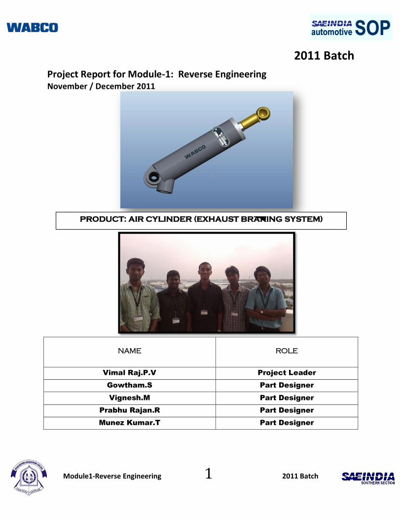
Project Report for Module-1: Reverse Engineering November / December 2011
NAME
ROLE
Vimal Raj.P.V Project Leader
Gowtham.S Part Designer
Vignesh.M Part Designer
Prabhu Rajan.R Part Designer
Munez Kumar.T Part Designer
PRODUCT: AIR CYLINDER (EXHAUST BRAKING SYSTEM)
Module1-Reverse Engineering 2 2011 Batch
automotive SOPautomotive SOPAcknowledgement
To,
Automotive SOP Coordinators and Initiators
SAE INDIA Southern Section.
We, the students of Rajalakshmi Engineering College are thankful to the
Initiators of Automotive SOP. It’s a wonderful learning experience rendered to us
by great minds from WABCO.The learning process was so tedious and of course
more informative. The guest lectures, the training aids and the teaching faculty
were all high-end. We thank all these great people for caring us and for making us
grasp new concepts in a very short span of time.
We are greatly thankful to Mr.S.Shanmugam and Mr.Selvamani for taking
pains to make us finish our project within time in a precise manner.
Thank You,
Yours truly,
Vimal Raj.P.V
Gowtham.S
Vignesh.M
Prabhu Rajan.R
Munez Kumar.T

Module1-Reverse Engineering 3 2011 Batch
automotive SOPautomotive SOPTable of contents
S.No Contents
1. Summary
2. Background Information
3. Product Structure
4. Function Block Diagrams
5. Product Function
6. Section View
7. Part Details
8. Bill of Materials
9. Conclusions and learning
10. References
11. Bibliography
Module1-Reverse Engineering 4 2011 Batch
automotive SOPautomotive SOP
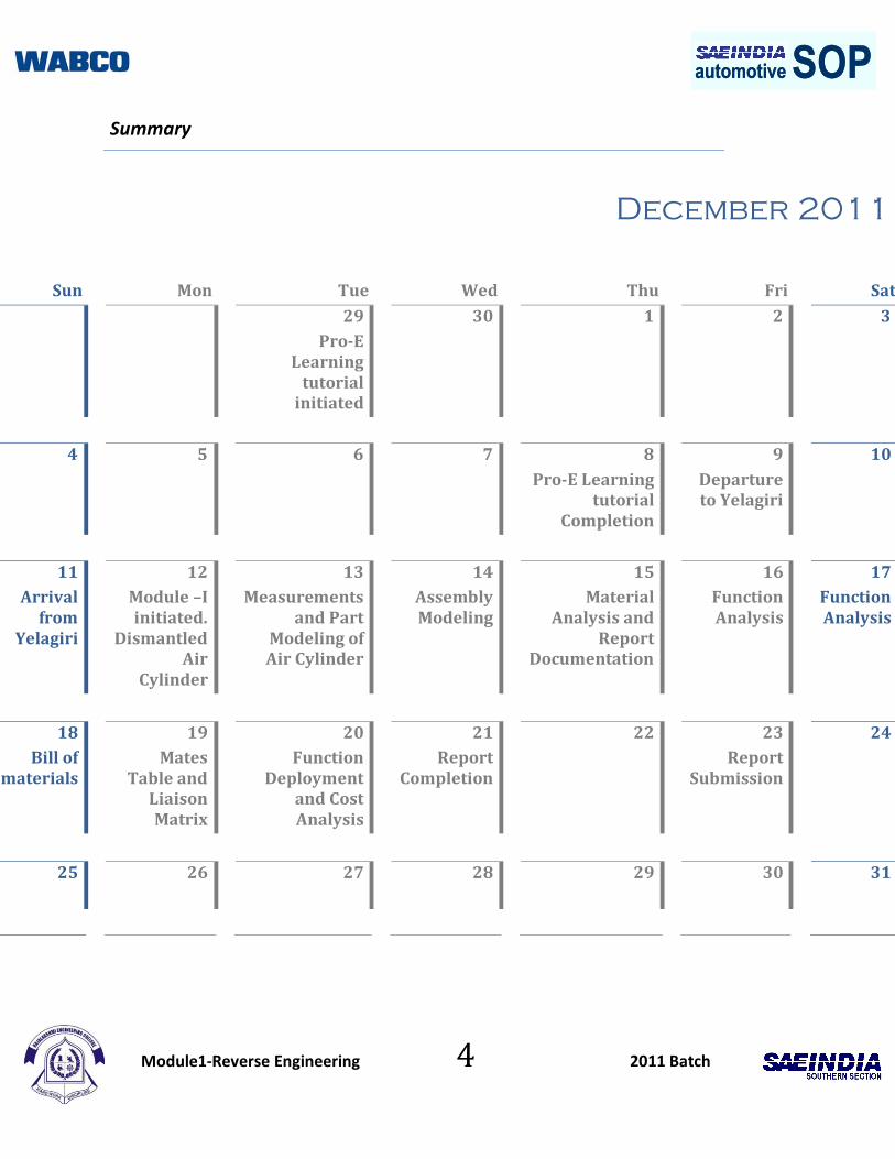
Summary
December 2011
Sun Mon Tue Wed Thu Fri Sat
29
Pro-E Learning
tutorial initiated
30 1 2 3
4 5 6 7
8
Pro-E Learning tutorial
Completion
9
Departure to Yelagiri
10
11
Arrival from
Yelagiri
12
Module –I initiated.
Dismantled Air
Cylinder
13
Measurements and Part
Modeling of Air Cylinder
14
Assembly Modeling
15
Material Analysis and
Report Documentation
16
Function Analysis
17
Function Analysis
18
Bill of materials
19
Mates Table and
Liaison Matrix
20
Function Deployment
and Cost Analysis
21
Report Completion
22
23
Report Submission
24
25 26 27 28 29 30 31
Module1-Reverse Engineering 5 2011 Batch
automotive SOPautomotive SOPBackground Information
There are only two main kinds of air cylinders: Double acting, and single acting. They come in all variations, shapes and sizes. Both kinds are useful for haunt work. Double acting cylinders are useful when you need to push in both directions, and single acting cylinders are useful when only a push in one direction is needed. And, sometimes 'in a pinch', you can adapt a double to act as a single, and a single to act as a double.
Air cylinders are measured by three main values: "pressure rating", the "bore", and "stroke"
Pressure rating
This is the maximum pressure the air cylinder can safely handle.
Bore The interior diameter of the cylinder.
Stroke The range of movement of the air cylinder's rod.
Air Cylinders are vital component of an Exhaust Air Brake System. The purpose of EBS is as follows.
1. Increases safety by reducing load on foundation brakes..
2. Improves cold weather operation, reduces thermal stress on intake valves, and allows
prolonged idling in extreme cold weather.
3. Aids in shifting of some engine, transmissions combinations.
4. Increases brake lining life.
5. Less noise, no additional muffling necessary.
6. Butterfly design minimizes weight and envelope size.
7. Guillotine design for heavy duty industrial applications.
8. Adjustable opening stop allows system tuning to your engine and exhaust system.
9. Actuating cylinder assembled with hi-temperature components and stainless steel shell.

Module1-Reverse Engineering 6 2011 Batch
automotive SOPautomotive SOPProduct Structure
Air Cylinder
Housing Piston Assembly Spring
Guide
Spring
Circlip Plate Washer Nut
Mounting Bush
Lip Seal Piston
Grommet
Filter Washer
Knuckle
Joint
Lock Pin Lever lock Pin
Module1-Reverse Engineering 7 2011 Batch
automotive SOPautomotive SOP
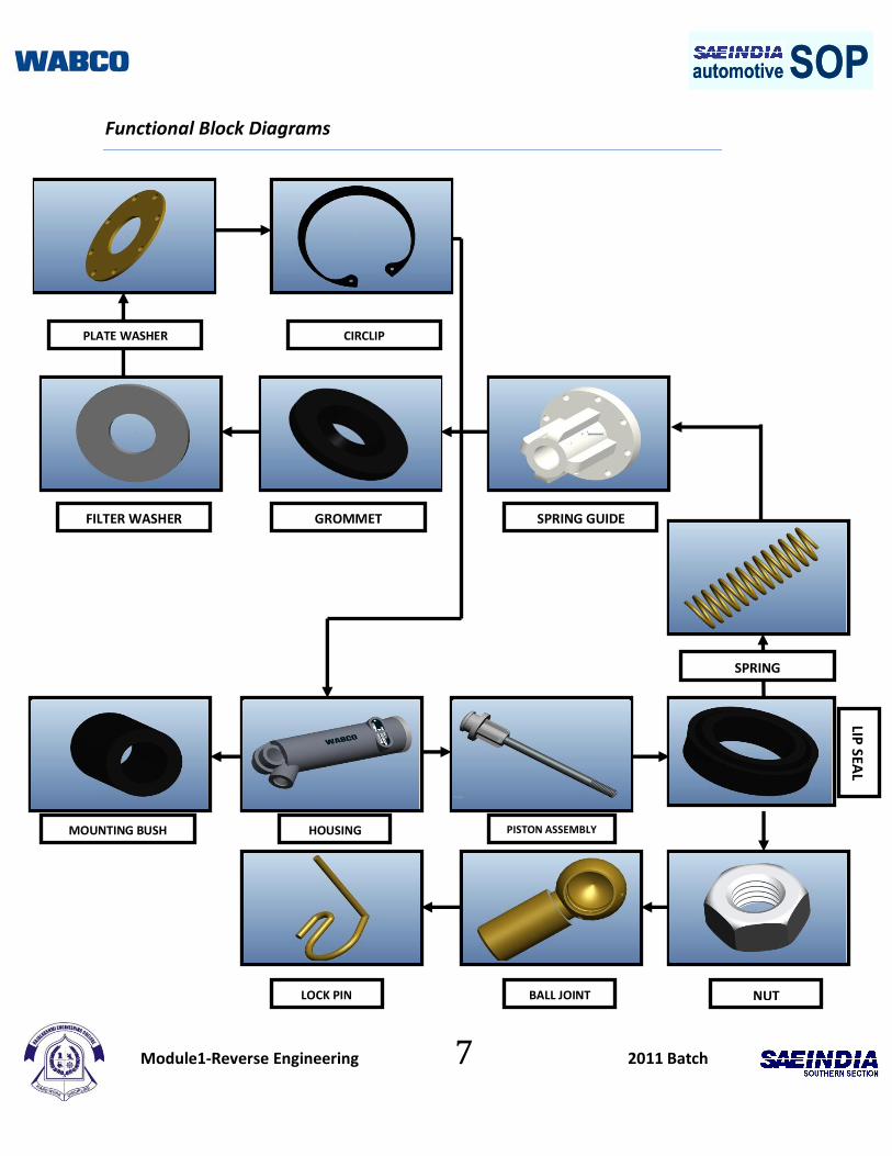
Functional Block Diagrams
HOUSING
LOCK PIN BALL JOINT NUT
MOUNTING BUSH PISTON ASSEMBLY
FILTER WASHER GROMMET SPRING GUIDE
PLATE WASHER
CIRCLIP
SPRING
LIP SEA
L
Module1-Reverse Engineering 8 2011 Batch
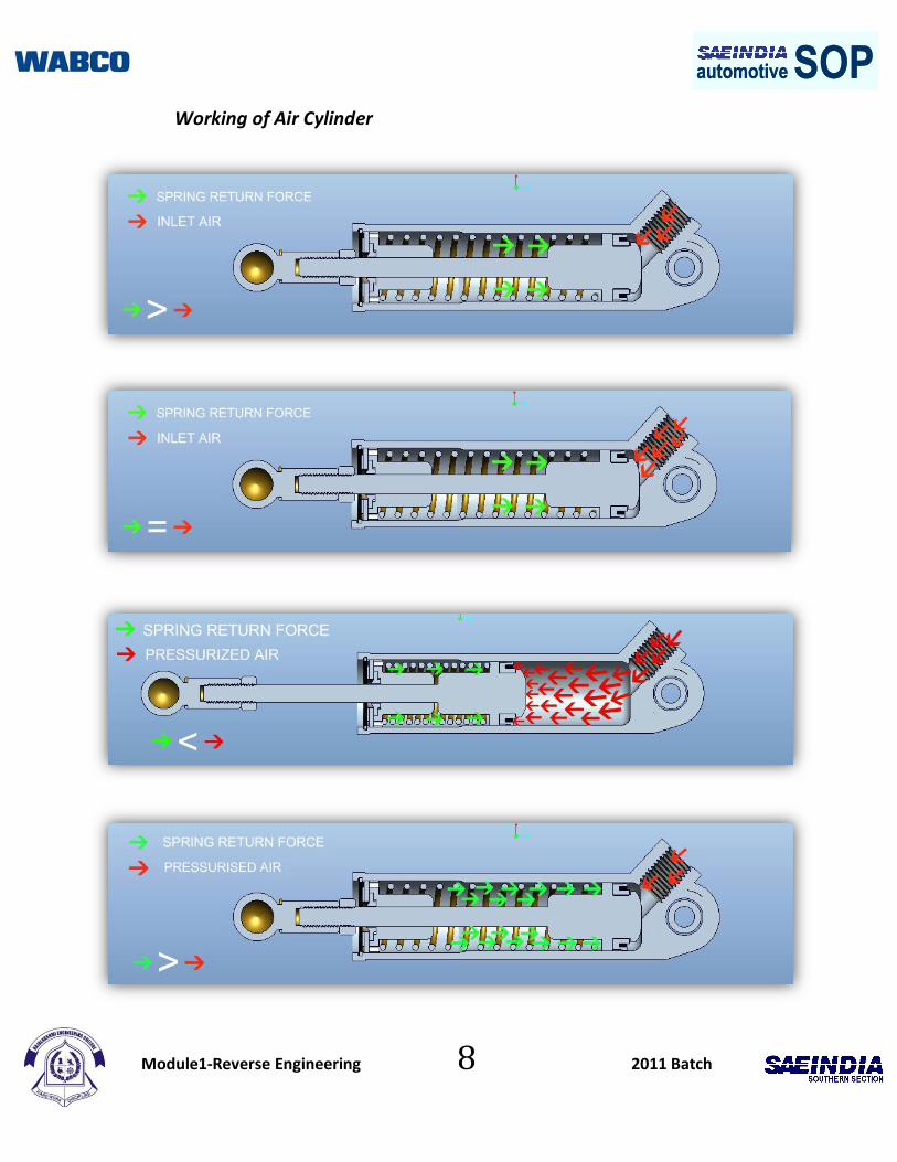
automotive SOPautomotive SOPWorking of Air Cylinder
Module1-Reverse Engineering 9 2011 Batch
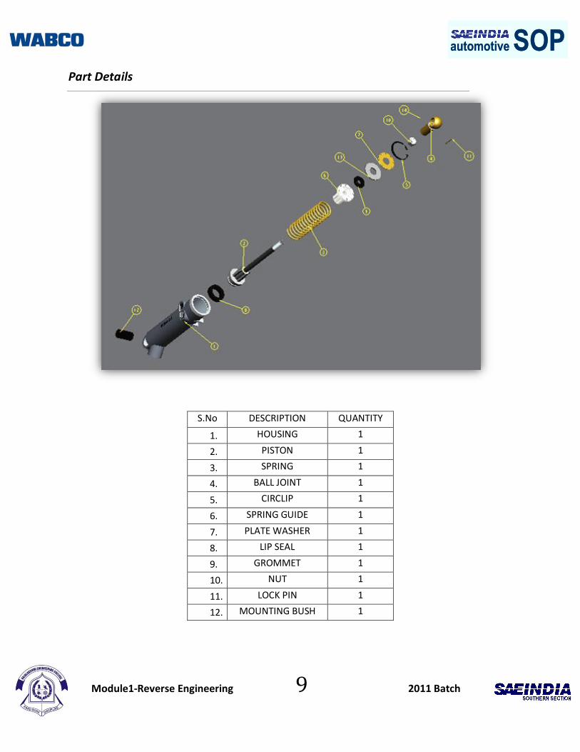
automotive SOPautomotive SOPPart Details
S.No DESCRIPTION QUANTITY
1. HOUSING 1
2. PISTON 1
3. SPRING 1
4. BALL JOINT 1
5. CIRCLIP 1
6. SPRING GUIDE 1
7. PLATE WASHER 1
8. LIP SEAL 1
9. GROMMET 1
10. NUT 1
11. LOCK PIN 1
12. MOUNTING BUSH 1
Module1-Reverse Engineering 10 2011 Batch
automotive SOPautomotive SOPPart Details
88. Part Details
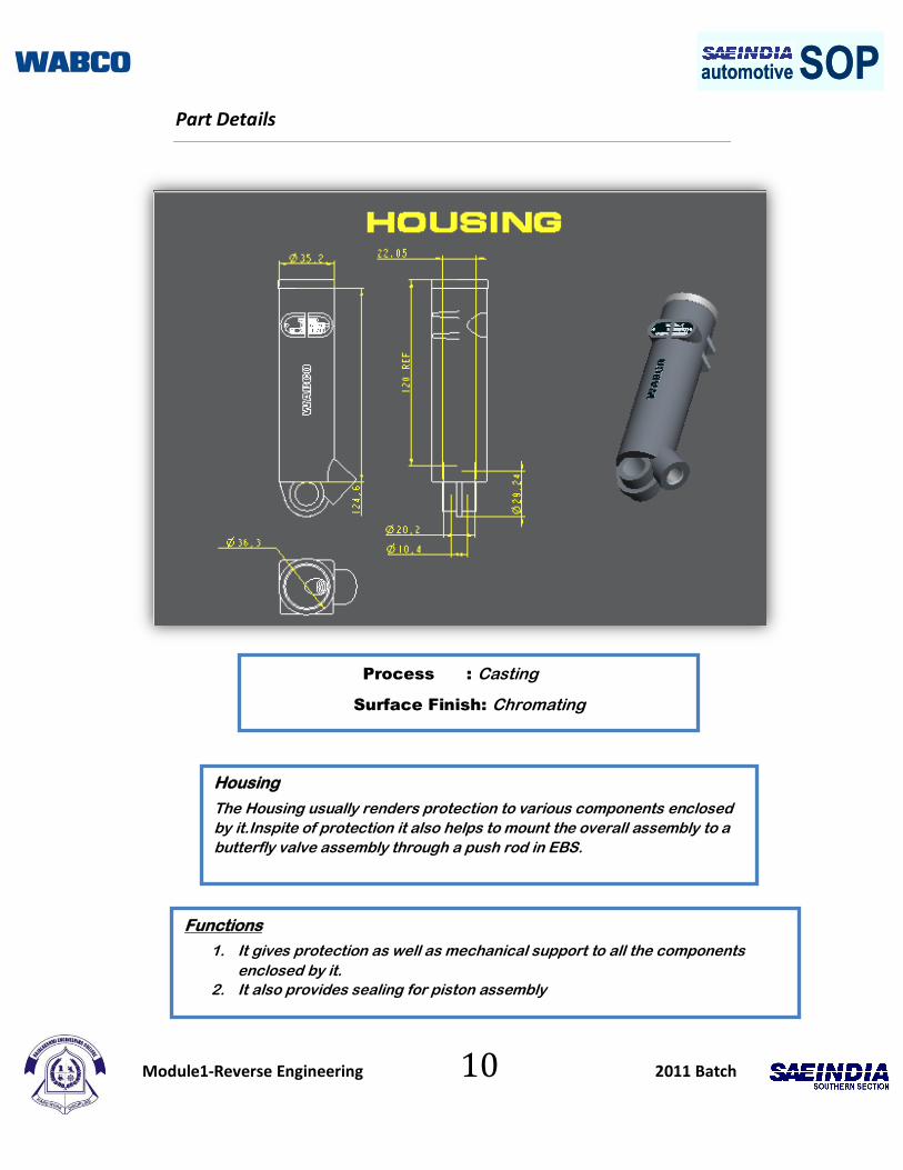
Process : Casting
Surface Finish: Chromating
Housing
The Housing usually renders protection to various components enclosed
by it.Inspite of protection it also helps to mount the overall assembly to a
butterfly valve assembly through a push rod in EBS.
Functions
1. It gives protection as well as mechanical support to all the components
enclosed by it.
2. It also provides sealing for piston assembly
Module1-Reverse Engineering 11 2011 Batch
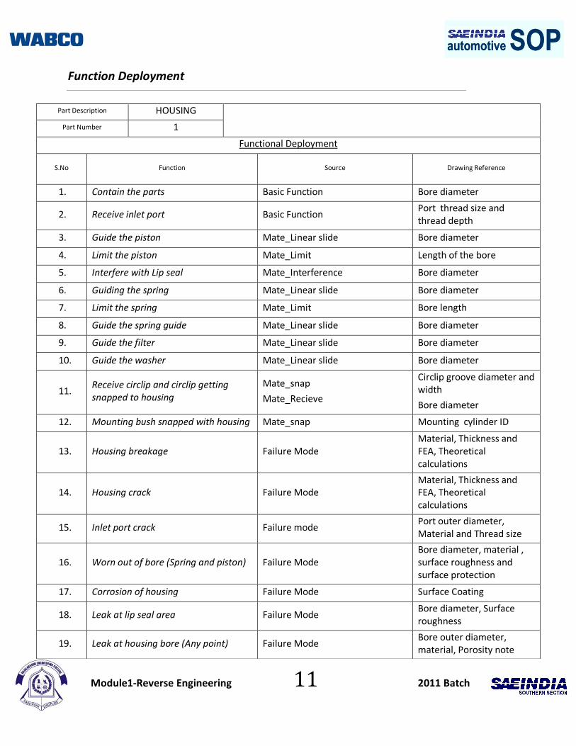
automotive SOPautomotive SOPFunction Deployment
Part Description HOUSING
Part Number 1
Functional Deployment
S.No Function Source Drawing Reference
1. Contain the parts Basic Function Bore diameter
2. Receive inlet port Basic Function Port thread size and thread depth
3. Guide the piston Mate_Linear slide Bore diameter
4. Limit the piston Mate_Limit Length of the bore
5. Interfere with Lip seal Mate_Interference Bore diameter
6. Guiding the spring Mate_Linear slide Bore diameter
7. Limit the spring Mate_Limit Bore length
8. Guide the spring guide Mate_Linear slide Bore diameter
9. Guide the filter Mate_Linear slide Bore diameter
10. Guide the washer Mate_Linear slide Bore diameter
11. Receive circlip and circlip getting snapped to housing
Mate_snap
Mate_Recieve
Circlip groove diameter and width
Bore diameter
12. Mounting bush snapped with housing Mate_snap Mounting cylinder ID
13. Housing breakage Failure Mode Material, Thickness and FEA, Theoretical calculations
14. Housing crack Failure Mode Material, Thickness and FEA, Theoretical calculations
15. Inlet port crack Failure mode Port outer diameter, Material and Thread size
16. Worn out of bore (Spring and piston) Failure Mode Bore diameter, material , surface roughness and surface protection
17. Corrosion of housing Failure Mode Surface Coating
18. Leak at lip seal area Failure Mode Bore diameter, Surface roughness
19. Leak at housing bore (Any point) Failure Mode Bore outer diameter, material, Porosity note

Module1-Reverse Engineering 12 2011 Batch
automotive SOPautomotive SOP
Part Detail
Process:Machining and Insert moulding
Piston Assembly
The piston rod is typically cold-rolled steel which attaches to the piston
and extends from the cylinder through the rod-end head. In double rod-
end cylinders, the actuator has a rod extending from both sides of the
piston and out both ends of the barrel.
Functions
1. They prevent the pressurized air from passing by the piston to the chamber on the opposite side
Module1-Reverse Engineering 13 2011 Batch
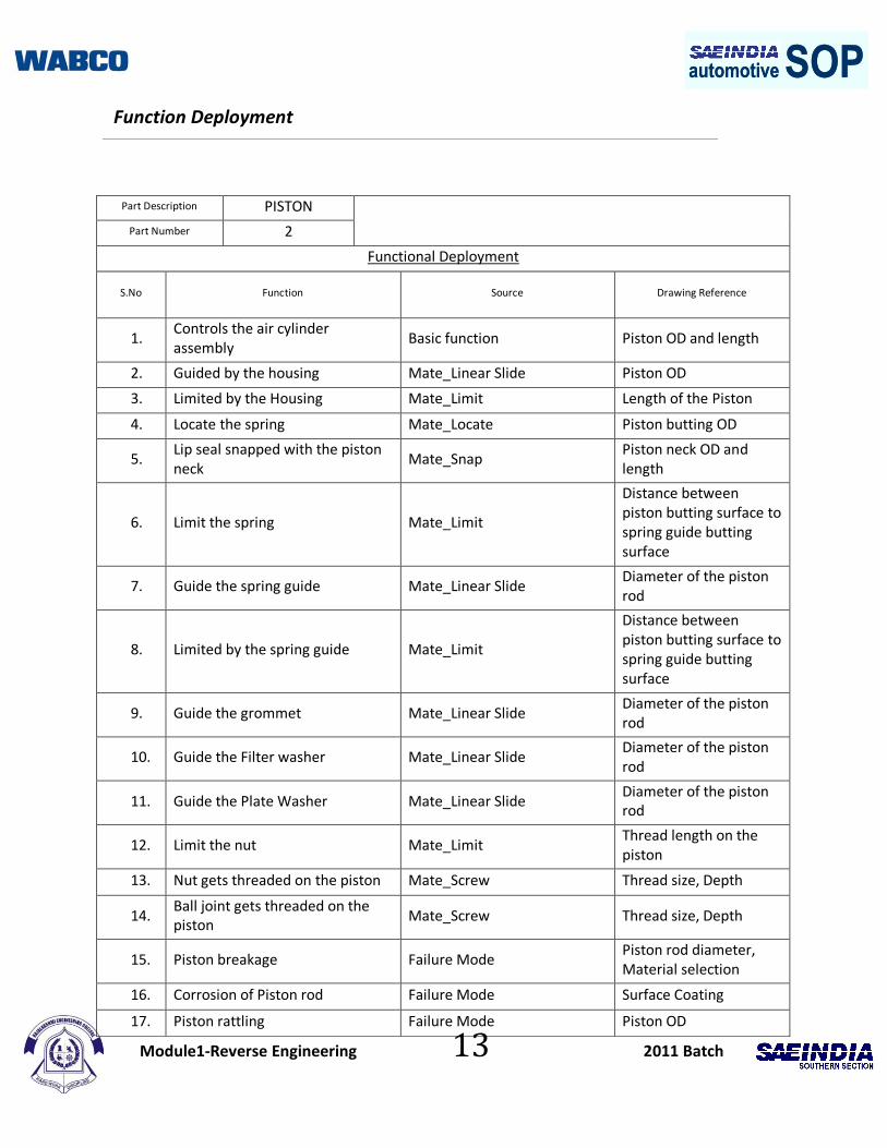
automotive SOPautomotive SOP Function Deployment
Part Description PISTON
Part Number 2
Functional Deployment
S.No Function Source Drawing Reference
1. Controls the air cylinder assembly
Basic function Piston OD and length
2. Guided by the housing Mate_Linear Slide Piston OD
3. Limited by the Housing Mate_Limit Length of the Piston
4. Locate the spring Mate_Locate Piston butting OD
5. Lip seal snapped with the piston neck
Mate_Snap Piston neck OD and length
6. Limit the spring Mate_Limit
Distance between piston butting surface to spring guide butting surface
7. Guide the spring guide Mate_Linear Slide Diameter of the piston rod
8. Limited by the spring guide Mate_Limit
Distance between piston butting surface to spring guide butting surface
9. Guide the grommet Mate_Linear Slide Diameter of the piston rod
10. Guide the Filter washer Mate_Linear Slide Diameter of the piston rod
11. Guide the Plate Washer Mate_Linear Slide Diameter of the piston rod
12. Limit the nut Mate_Limit Thread length on the piston
13. Nut gets threaded on the piston Mate_Screw Thread size, Depth
14. Ball joint gets threaded on the piston
Mate_Screw Thread size, Depth
15. Piston breakage Failure Mode Piston rod diameter, Material selection
16. Corrosion of Piston rod Failure Mode Surface Coating
17. Piston rattling Failure Mode Piston OD

Module1-Reverse Engineering 14 2011 Batch
automotive SOPautomotive SOP18.
Wear and tear of piston (top and bore guiding surface)
Failure Mode Piston OD,Material Selection
19. Seperation of piston rod and piston
Failure Mode Projections on the piston rod
20. Leakage of Lip seal(at piston interface)
Failure Mode Surface Finish of piston
21. Buckling of piston rod Failure Mode Piston rod OD,Material Selection
Module1-Reverse Engineering 15 2011 Batch
automotive SOPautomotive SOP
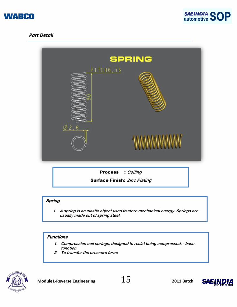
Part Detail
Process : Coiling
Surface Finish: Zinc Plating
Spring
1. A spring is an elastic object used to store mechanical energy. Springs are usually made out of spring steel.
Functions
1. Compression coil springs, designed to resist being compressed. - base function
2. To transfer the pressure force
Module1-Reverse Engineering 16 2011 Batch
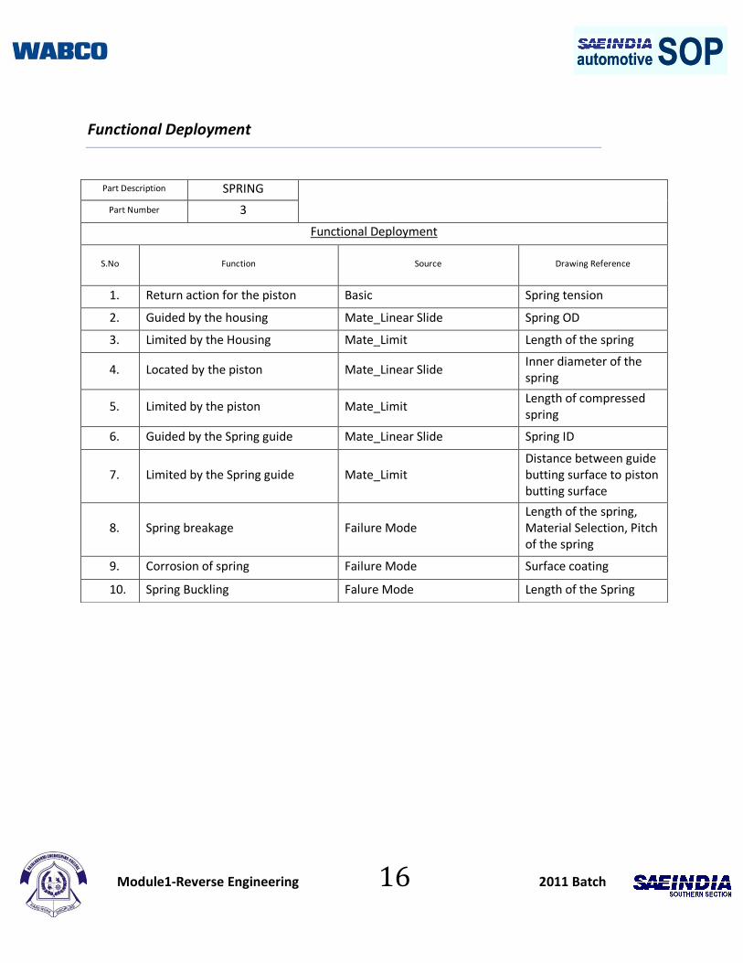
automotive SOPautomotive SOP
Functional Deployment
Part Description SPRING
Part Number 3
Functional Deployment
S.No Function Source Drawing Reference
1. Return action for the piston Basic Spring tension
2. Guided by the housing Mate_Linear Slide Spring OD
3. Limited by the Housing Mate_Limit Length of the spring
4. Located by the piston Mate_Linear Slide Inner diameter of the spring
5. Limited by the piston Mate_Limit Length of compressed spring
6. Guided by the Spring guide Mate_Linear Slide Spring ID
7. Limited by the Spring guide Mate_Limit Distance between guide butting surface to piston butting surface
8. Spring breakage Failure Mode Length of the spring, Material Selection, Pitch of the spring
9. Corrosion of spring Failure Mode Surface coating
10. Spring Buckling Falure Mode Length of the Spring
Module1-Reverse Engineering 17 2011 Batch
automotive SOPautomotive SOPPart Detail
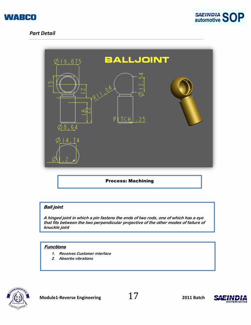
Process: Machining
Functions
1. Receives Customer interface
2. Absorbs vibrations
Ball joint
A hinged joint in which a pin fastens the ends of two rods, one of which has a eye that fits between the two perpendicular projective of the other modes of failure of knuckle joint

Module1-Reverse Engineering 18 2011 Batch
automotive SOPautomotive SOPFunctional Deployment
Part Description BALL JOINT
Part Number 4
Functional Deployment
S.No Function Source Drawing Reference
1. Connects to customer interface
Basic Bore diameter and depth
2. Screwed to the piston Mate_Screw Thread size and depth
3. Limited by the nut Mate_Limit Thread depth
4. Lock pin snapped with Ball joint neck
Mate_Snap Neck diameter and width
5. Corrosion of ball joint Failure Mode Surface coating
6. Wear and tear of Ball joint(Inner surface)
Failure Mode Bore diameter, Material Selection
7. Breakage of ball joint Failure Mode Neck OD
Module1-Reverse Engineering 19 2011 Batch
automotive SOPautomotive SOPPart Detail
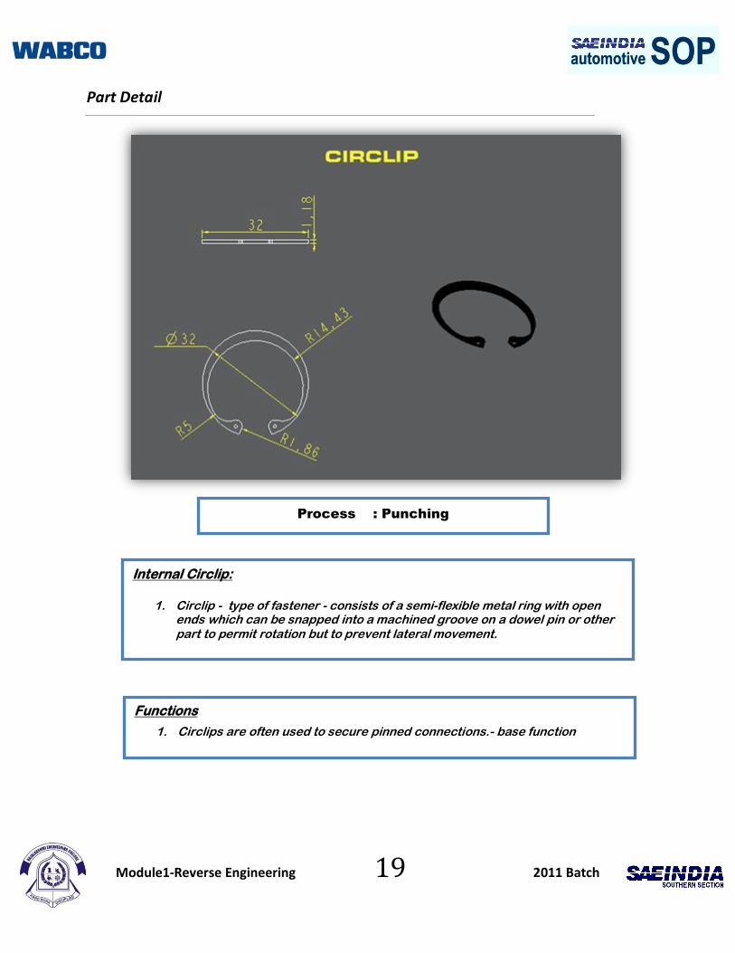
Process : Punching
Internal Circlip:
1. Circlip - type of fastener - consists of a semi-flexible metal ring with open ends which can be snapped into a machined groove on a dowel pin or other part to permit rotation but to prevent lateral movement.
Functions
1. Circlips are often used to secure pinned connections.- base function

Module1-Reverse Engineering 20 2011 Batch
automotive SOPautomotive SOPFunctional Deployment
Part Description CIRCLIP
Part Number 5
Functional Deployment
S.No Function Source Drawing Reference
1. Limits all the parts Basic Circlip ID
2. Snapped in the housing Mate_Snap Circlip OD and thickness
3. Limit the plate washer Mate_Limit Circlip ID
4. Breakage of Circlip Failure mode Thickness of the circlip and material selection
5. Corrosion of Circlip Failure Mode Surface Coating
6. Breakage of CIrclip(At holes) Failure Mode Hole diameter
7. Inflexibility of CIrclip Failure Mode Surface Finish, Distance between the holes
Module1-Reverse Engineering 21 2011 Batch
automotive SOPautomotive SOPPart Detail
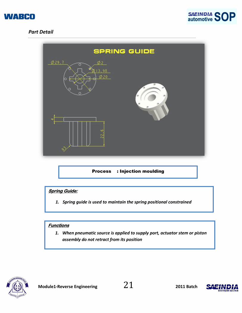
Process : Injection moulding
Spring Guide:
1. Spring guide is used to maintain the spring positional constrained
Functions
1. When pneumatic source is applied to supply port, actuator stem or piston
assembly do not retract from its position
Module1-Reverse Engineering 22 2011 Batch
automotive SOPautomotive SOPFunction Deployment
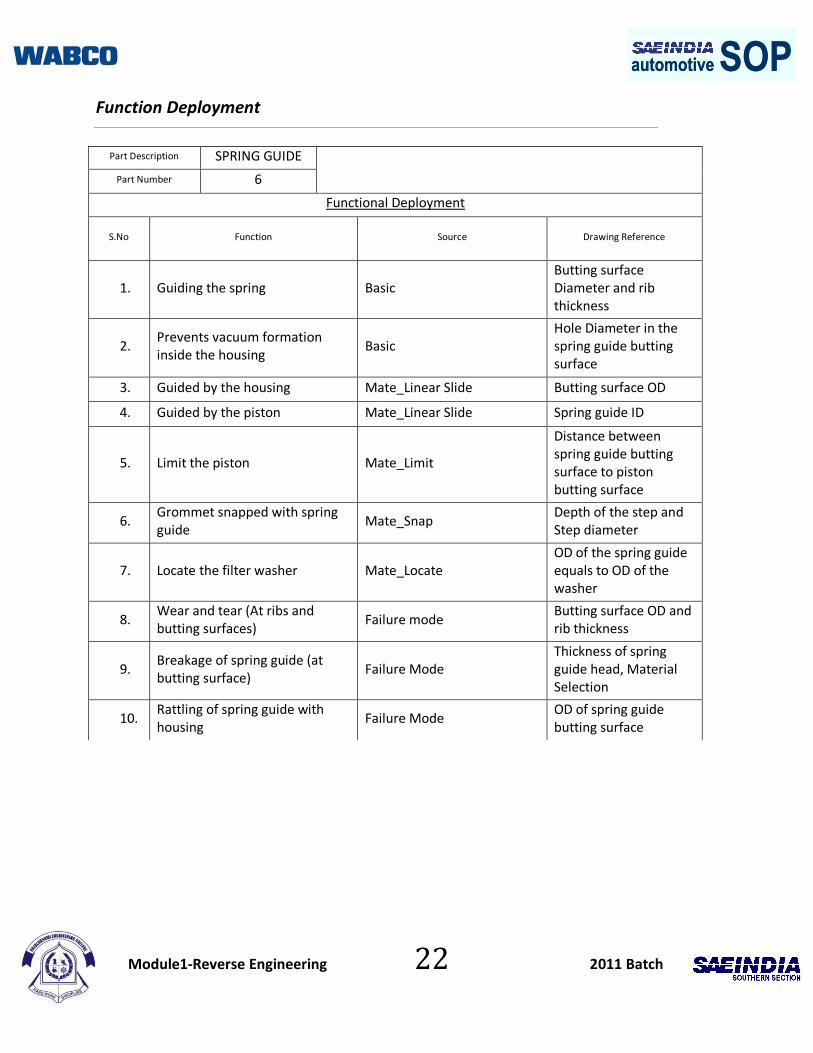
Part Description SPRING GUIDE
Part Number 6
Functional Deployment
S.No Function Source Drawing Reference
1. Guiding the spring Basic Butting surface Diameter and rib thickness
2. Prevents vacuum formation inside the housing
Basic Hole Diameter in the spring guide butting surface
3. Guided by the housing Mate_Linear Slide Butting surface OD
4. Guided by the piston Mate_Linear Slide Spring guide ID
5. Limit the piston Mate_Limit
Distance between spring guide butting surface to piston butting surface
6. Grommet snapped with spring guide
Mate_Snap Depth of the step and Step diameter
7. Locate the filter washer Mate_Locate OD of the spring guide equals to OD of the washer
8. Wear and tear (At ribs and butting surfaces)
Failure mode Butting surface OD and rib thickness
9. Breakage of spring guide (at butting surface)
Failure Mode Thickness of spring guide head, Material Selection
10. Rattling of spring guide with housing
Failure Mode OD of spring guide butting surface

Module1-Reverse Engineering 23 2011 Batch
automotive SOPautomotive SOPPart Detail
1
Process: Punching
Plate Washer
The plate cylinder washer is a small flat ring made of rubber, metal or plastic
placed between two surfaces
Functions
.
1. The cylinder washer is a small flat ring made of metal, rubber, or
plastic fixed under a nut or the head of a bolt to spread the pressure
when tightened or between two joining surfaces as a spacer or seal
for the hollow tube in an engine, shaped like a cylinder, inside which
the piston moves

Module1-Reverse Engineering 24 2011 Batch
automotive SOPautomotive SOP Function Deployment
Part Description PLATE WASHER
Part Number 7
Functional Deployment
S.No Function Source Drawing Reference
1. Uniformly distributes force Basic OD of plate washer
2. Prevents vacuum formation Basic Hole diameter
3. Guided by the housing Mate_linear slide Plate washer OD
4. Guide the piston Mate_linear slide Plate washer ID
5. Locate the filter washer Mate_locate Plate washer OD equal to OD of filter washer
6. Limited by the circlip Mate_limit OD of plate washer
7. Plate washer breakage Failure mode Thickness of plate washer, material selection
8. Bending of plate washer Failure mode Thickness of plate washer, material selection
9. Corrosion of plate washer Failure mode Surface coating
10. Wear of plate washer (at round surface)
Failure mode OD of plate washer, material selection
11. Plate washer holes breakage Failure mode Hole diameter and thickness of plate washer
Module1-Reverse Engineering 25 2011 Batch
automotive SOPautomotive SOPPart Detail
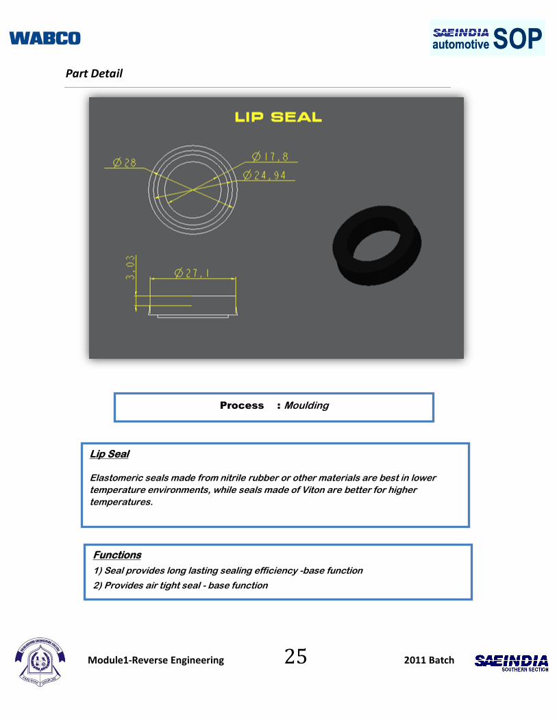
Process : Moulding
Lip Seal
Elastomeric seals made from nitrile rubber or other materials are best in lower
temperature environments, while seals made of Viton are better for higher
temperatures.
Functions
1) Seal provides long lasting sealing efficiency -base function
2) Provides air tight seal - base function
Module1-Reverse Engineering 26 2011 Batch
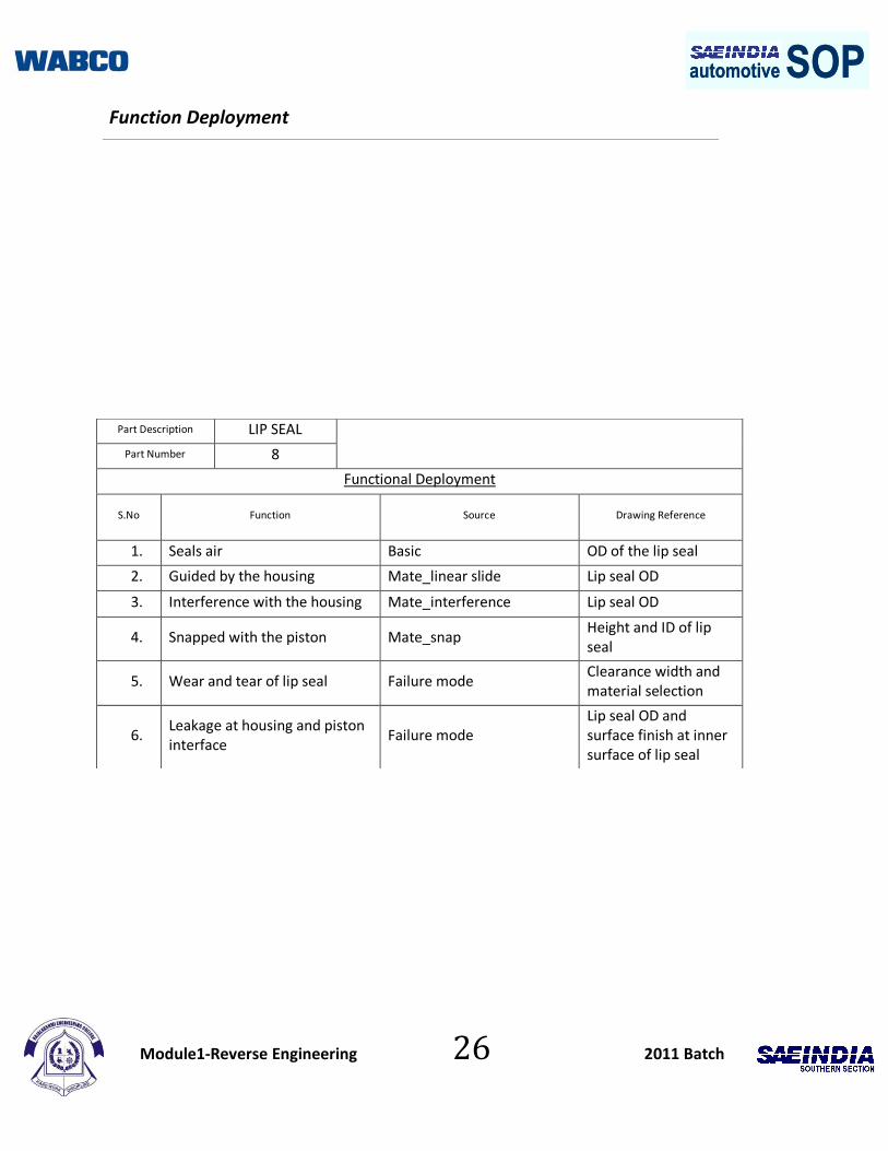
automotive SOPautomotive SOP Function Deployment
Part Description LIP SEAL
Part Number 8
Functional Deployment
S.No Function Source Drawing Reference
1. Seals air Basic OD of the lip seal
2. Guided by the housing Mate_linear slide Lip seal OD
3. Interference with the housing Mate_interference Lip seal OD
4. Snapped with the piston Mate_snap Height and ID of lip seal
5. Wear and tear of lip seal Failure mode Clearance width and material selection
6. Leakage at housing and piston interface
Failure mode Lip seal OD and surface finish at inner surface of lip seal
Module1-Reverse Engineering 27 2011 Batch
automotive SOPautomotive SOPPart Detail
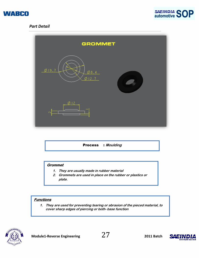
Process : Moulding
Grommet
1. They are usually made in rubber material
2. Grommets are used in place on the rubber or plastics or
plate.
Functions
1. They are used for preventing tearing or abrasion of the pieced material, to cover sharp edges of piercing or both- base function

Module1-Reverse Engineering 28 2011 Batch
automotive SOPautomotive SOP
Functional Deployment
Part Description GROMMET
Part Number 9
Functional Deployment
S.No Function Source Drawing Reference
1. Prevents water and dirt to enter into the housing
Basic OD ,ID and step height of the grommet
2. Guided by the piston Mate_linear slide ID of grommet
3. Snapped with the spring guide Mate_snap OD ,ID and step height of the grommet
4. Locate the filter washer Mate_locate ID of grommet equals ID of filter washer
5. Wear and tear at the inner surface of the grommet
Failure mode ID of grommet,material selection
6. Leakage at the grommet spring guide interface
Failure mode Surface finish
Module1-Reverse Engineering 29 2011 Batch
automotive SOPautomotive SOP8. Part Details
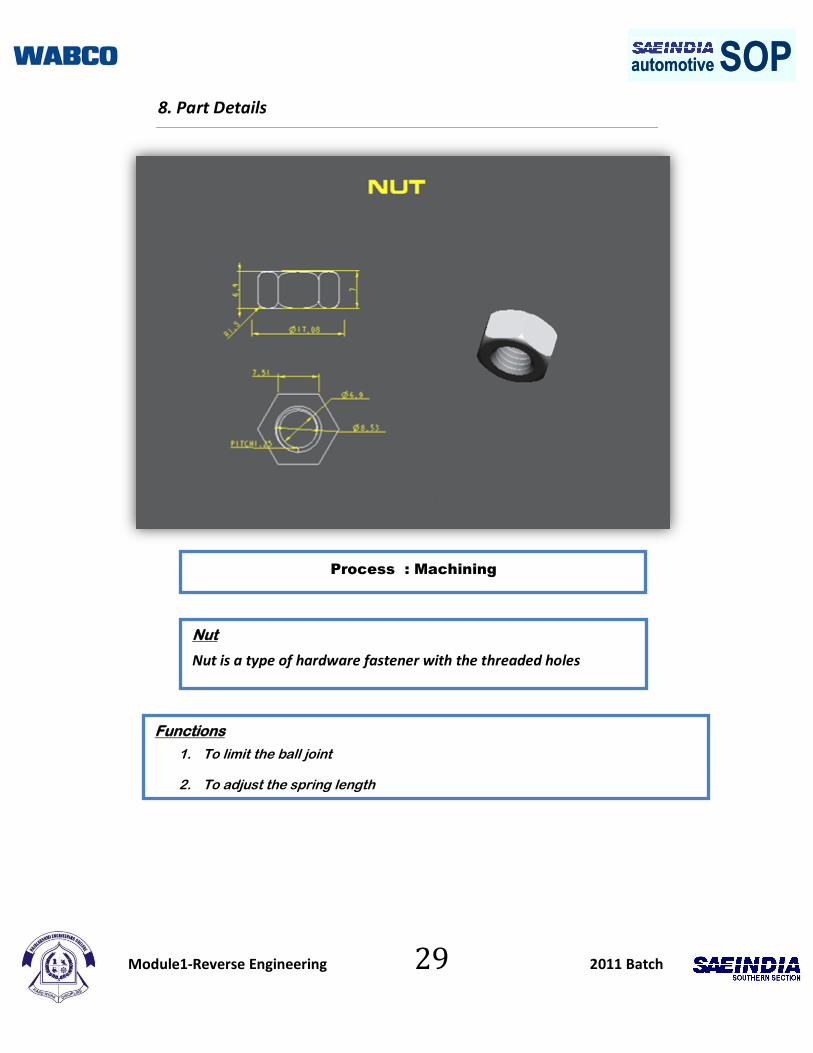
Process : Machining
Nut
Nut is a type of hardware fastener with the threaded holes
Functions
1. To limit the ball joint
2. To adjust the spring length

Module1-Reverse Engineering 30 2011 Batch
automotive SOPautomotive SOPFunction Deployment
Part Description NUT
Part Number 10
Functional Deployment
S.No Function Source Drawing Reference
1. For locking the ball joint Basic ID of nut
2. Screwed with piston Mate_screw Pitch and thread size
3. Limit the ball joint Mate_limit Thread depth
4. Wear and tear of thread Failure mode Thread size, Material selection
5. Corrosion of nut Failure mode Surface coating, material selection
6. Breakage due to over tightening
Failure mode Thickness and material selection

Module1-Reverse Engineering 31 2011 Batch
automotive SOPautomotive SOP Part Details
Process : Bending
Lock Pin
A peg or pin that is inserted through a hole or holes and locks two
parts together
Functions
1. Used to arrest or lock the lever in ball joint

Module1-Reverse Engineering 32 2011 Batch
automotive SOPautomotive SOPFunction Deployment
Part Description LOCK PIN
Part Number 11
Functional Deployment
S.No Function Source Drawing Reference
1. For locking the customer interface with the air cylinder
Basic Diameter of the lock pin
2. Snapped with the ball joint Mate_snap ID of lock pin and diameter of lock pin
3. Bending of lock pin Failure mode Diameter of lock pin
4. Insert failure Failure mode ID of lock pin, material selection
5. Corrosion of lock pin Failure mode Surface coating
Module1-Reverse Engineering 33 2011 Batch
automotive SOPautomotive SOPPart Details
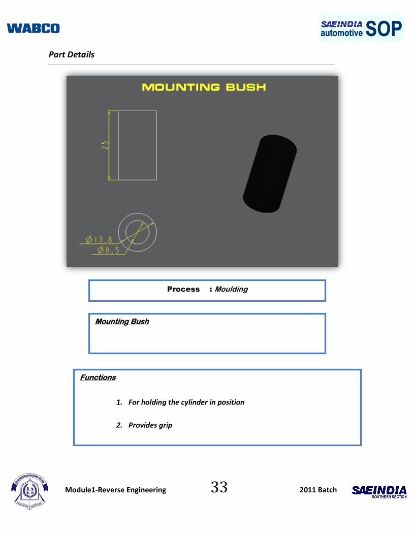
Process : Moulding
Mounting Bush
Functions
1. For holding the cylinder in position
2. Provides grip

Module1-Reverse Engineering 34 2011 Batch
automotive SOPautomotive SOPFunction Deployment
Part Description MOUNTING
BUSH
Part Number 12
Functional Deployment
S.No Function Source Drawing Reference
1. Provides grip at the customer interface
Basic OD of the mounting bush
2. Protects the housing mounting part by avoiding metal to metal contact
Basic Thickness of mounting bush
3. Snapped with the housing Mate_snap OD of mounting bush
4. Wear and tear of mounting bush at inner surface
Failure mode ID of mounting bush and material selection
Module1-Reverse Engineering 35 2011 Batch
automotive SOPautomotive SOPPart Details
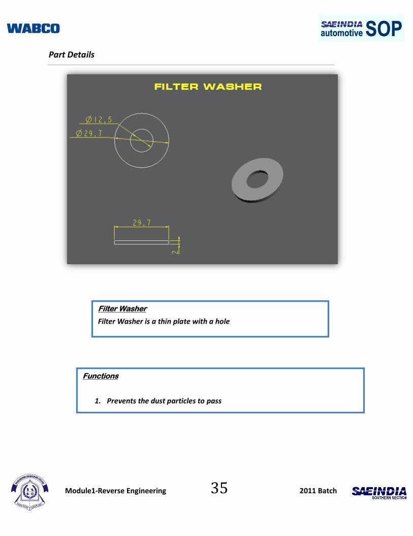
Filter Washer
Filter Washer is a thin plate with a hole
Functions
1. Prevents the dust particles to pass
Module1-Reverse Engineering 36 2011 Batch
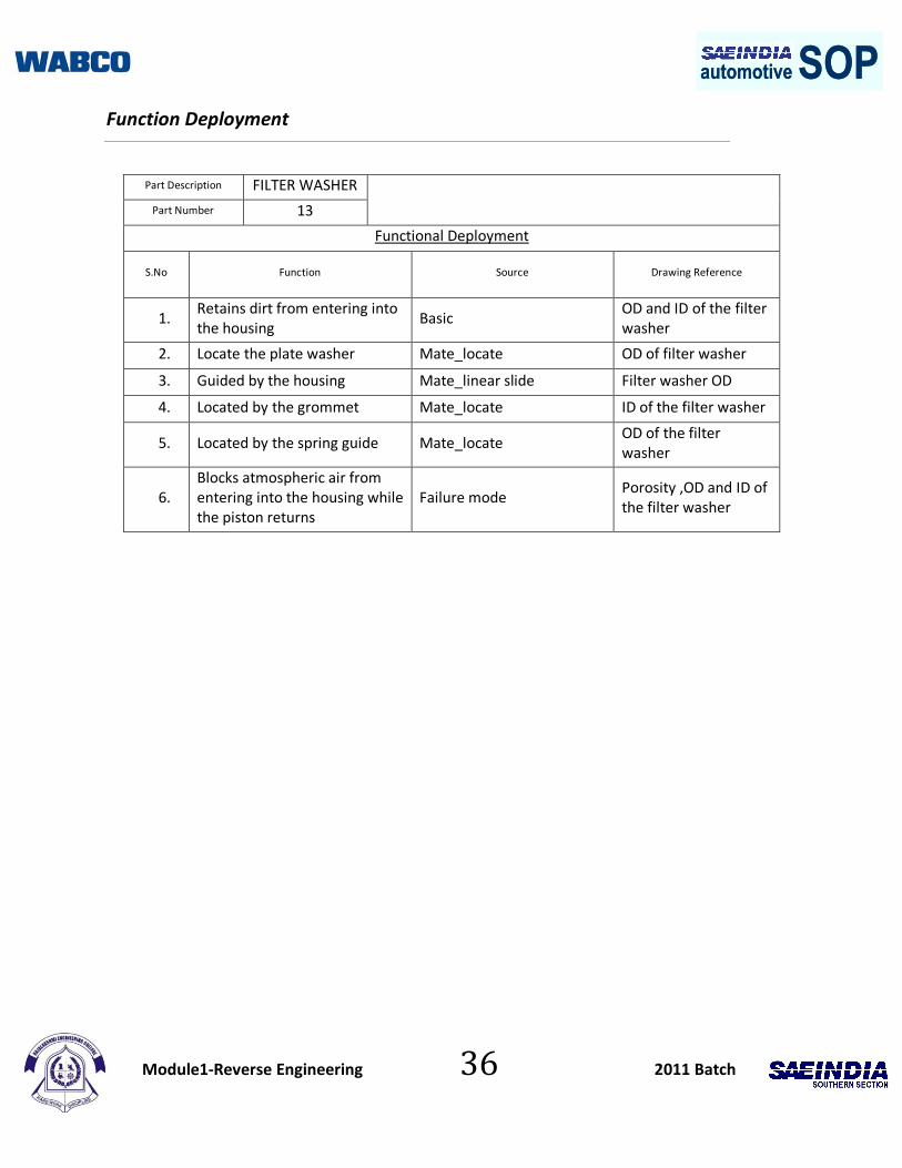
automotive SOPautomotive SOPFunction Deployment
Part Description FILTER WASHER
Part Number 13
Functional Deployment
S.No Function Source Drawing Reference
1. Retains dirt from entering into the housing
Basic OD and ID of the filter washer
2. Locate the plate washer Mate_locate OD of filter washer
3. Guided by the housing Mate_linear slide Filter washer OD
4. Located by the grommet Mate_locate ID of the filter washer
5. Located by the spring guide Mate_locate OD of the filter washer
6. Blocks atmospheric air from entering into the housing while the piston returns
Failure mode Porosity ,OD and ID of the filter washer
Module1-Reverse Engineering 37 2011 Batch
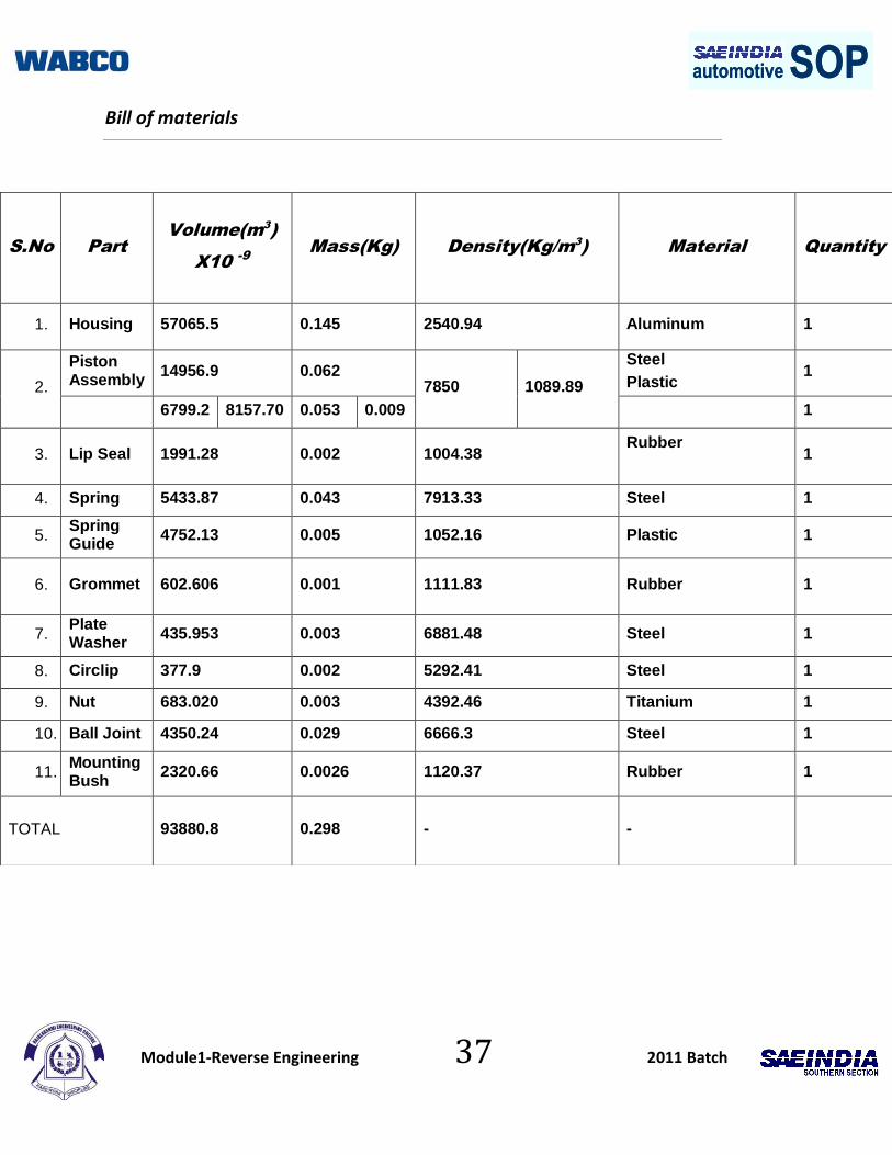
automotive SOPautomotive SOPBill of materials
S.No Part
Volume(m3
)
X10 -9
Mass(Kg) Density(Kg/m3
)
Material
Quantity
1. Housing 57065.5 0.145 2540.94 Aluminum 1
2.
Piston Assembly
14956.9 0.062 7850 1089.89
Steel
Plastic 1
6799.2 8157.70 0.053 0.009 1
3. Lip Seal 1991.28 0.002 1004.38 Rubber
1
4. Spring 5433.87 0.043 7913.33 Steel 1
5. Spring Guide
4752.13 0.005 1052.16 Plastic 1
6. Grommet 602.606 0.001 1111.83 Rubber 1
7. Plate Washer
435.953 0.003 6881.48 Steel 1
8. Circlip 377.9 0.002 5292.41 Steel 1
9. Nut 683.020 0.003 4392.46 Titanium 1
10. Ball Joint 4350.24 0.029 6666.3 Steel 1
11. Mounting Bush
2320.66 0.0026 1120.37 Rubber 1
TOTAL
93880.8 0.298 - -

Module1-Reverse Engineering 38 2011 Batch
automotive SOPautomotive SOPCost Analysis
S.No Part Name
Raw Material Cost
(Rs)
Manufacturing Cost
(Rs)30 %
Over heads cost
(Rs)20%
Transportation cost
(Rs)5%
Quantity
Direct Part Cost/component
(Rs)
1. Housing 19.00 6.00 4.00 1.00 1 30.00
2. Piston Assembly
9.50 3.00 2.00 0.50 1 15.00
3. Lip Seal 0.50 0.50 0.25 0.25 1 1.50
4. Spring 2.50 0.75 0.50 0.50 1 4.25
5. Spring Guide
3.50 1.00 0.75 0.50 1 5.75
6. Grommet 0.25 0.50 0.25 0.25 1 1.25
7. Plate Washer
0.50 1.00 0.50 0.25 1 2.25
8. Circlip 0.50 0.50 0.25 0.25 1 1.50
9. Nut 3.25 1.00 1.00 0.25 1 5.50
10. Ball Joint Assembly
1.50 0.50 0.50 0.50 1 3.00
11. Mounting Bush
0.50 0.25 0.25 0.25 1 1.25
12. Overall Cost 71.25
Module1-Reverse Engineering 39 2011 Batch
automotive SOPautomotive SOP
Conclusion and Learning
We learnt about various terminologies in the industrial and corporate sectors.
We studied how to analyze a component and to create a model through pro-
engineer software.
We analyzed the working of every part within the component.
We are now able to deploy the function of a component.

Module1-Reverse Engineering 40 2011 Batch
automotive SOPautomotive SOP References
http://www.matbase.com/
http://www.engineeringtoolbox.com/
http://www.ehow.com/how_8486269_calculate-manufacturing-cost-per-unit.html
http://www.wikipedia.org/
http://en.wikipedia.org/wiki/Exhaust_brakes
http://www.matweb.com/

Module1-Reverse Engineering 41 2011 Batch
automotive SOPautomotive SOP
Bibliography
1) Donald R.Askeland (a), Pradeep P.Fulay (b), D.K.Bhattacharya
(2007)."Materials Science and Engineering"- Cengage Publication.
2) Rao. (2005)."Handbook of Mechanical, Civil, Electronics"
3) PSG College of Technology (Publication) (2009)."Design data book"
4) R.K.Bansal (2003)."Strength of Material”
5) Gupta (1995)."Strength of Material"
6) V.Ganesan (3rd edition)."Internal Combustion Engines"- "Tata McGraw Hill"
7) John.B.Heywood." Fundamentals of Internal Combustion Engines”
8) Kirpal Singh."Automotive Engineering 1 & 2”