air distribution service certification
TRANSCRIPT
AIR DISTRIBUTION SERVICE CERTIFICATION
Certification Information
Scope - Tests a candidate's knowledge of the installation, service, maintenance, and repair of HVAC systems. System sizes are limited to
12,000 CFM or less airflow.
Qualifications
Y This is a test and certification for TECHNICIANS in the HVAC industry. The test is designed for top level service
technicians. This test for certification is not intended for the HVAC system designer, sales force, or the engineering
community. To become NATE-certified, you must pass this specialty and a CORE SERVICE exam.
Y This test will measure what 80% of the Air Distribution candidates have an 80% likelihood of encountering at least once
during the year on a NATIONAL basis.
Y Suggested requirement is two years of field experience working on Air Distribution systems as a service technician and
technical training for theoretical knowledge.
Test Specifications
Closed Book 2.5 Hour Time Limit 100 Questions Passing Score: PASS/FAIL Listed are the percentages of questions that will be in each section of the Air Distribution exam.
SECTION AREA DESCRIPTION SECTION PERCENTAGE
Installation 20%
Service 40%
System Components 25%
Applied Knowledge 15%
Air Distribution Industry References
The reference materials listed below will be helpful in preparing for this exam. These materials may NOT contain all of the information necessary to be
competent in this specialty or to pass the exam.
• American National Standards Institute (ANSI) / Air Conditioning Contractors of America (ACCA) Manuals - Latest Edition
• “D”, “J”, “QI” - Quality Installation, and “S”
• ACCA Manuals “T” and “RS” - Latest Editions
• ACCA Residential Duct Diagnostics and Repair - Latest Edition
• AHRI-Hydronics Section-IBO/RAH Latest Edition
• International Energy Conservation Code - Latest Edition with Addendum
• International Mechanical Code - Latest Edition with Addendum
• International Plumbing Code - Latest Edition with Addendum
• Uniform Mechanical Code - Latest Edition with Addendum
• Specification of Energy-Efficient Installation and Maintenance Practices for Residential HVAC Systems developed by Consortium for Energy
Efficiency (CEE) - Latest Edition with Addendum
• ASHRAE Standard-62.2 - Latest Edition with Addendum
• ANSI / ASHRAE Standard-152-2004 - Latest Edition with Addendum
• ENERGY STAR™ Home Sealing Standards - Latest Edition with Addendum
• Duct Calculators – Sheet Metal, Ductboard, and Flexible Duct
• American National Standards Institute (ANSI) / Sheet Metal and Air Conditioning Contractors’ National Association, Inc. (SMACNA) Manuals
• HVAC Duct Construction Standards - Metal and Flexible
• Sheet Metal and Air Conditioning Contractors’ National Association, Inc. (SMACNA) Manuals
• Fibrous Glass Duct Construction Standards, Residential Comfort System Installation Standards Manual, and HVAC Air Duct
Leakage Test Manual
• Air Diffusion Council Flexible Duct Performance & Installation Standards
• North American Insulation Manufacturers Association (NAIMA) Manuals
• Fibrous Glass Duct Construction Standards and A Guide to Insulated Air Duct Systems
• International Fuel Gas Code – Latest Edition with Addendum
• National Fuel Gas Code – Latest Edition with Addendum
Passing Score Development Process
The passing scores for the NATE tests were established using a systematic procedure (a Passing Score Study). This procedure employed the judgment of
experienced HVAC professionals and educators representing various HVAC specialties and geographical areas. The passing scores were set using
criteria defining competent performance. The passing score for different test forms may vary slightly due to the comparative difficulty of the test
questions.
Exam Copyrights
All testing documents and questions are the copyrighted property of North American Technician Excellence Inc.-NATE. It is forbidden under federal
copyright law to copy, reproduce, record, distribute or display these documents or questions by any means, in whole or part, without written permission
from NATE. Doing so may subject you to severe civil and/or criminal penalties, including imprisonment and/or fines for criminal violations.

(C) 2006 NATE All Rights Reserved Page: 1
Air Distribution - Low Pressure - Service
Air Distribution - Low Pressure
Service INSTALLATION
DUCT FABRICATION
DUCT FABRICATION EQUIPMENT
Ductboard tools - 90 V-groove, end cutoff, female shiplap, hole cutter, stapler, etc.
Flex tools - tensioning strap tools, knives, etc.
Metal tools - metal snips, sheers, benders, breaks, hand formers, calipers, rulers, stapler, etc.
FABRICATION TECHNIQUES FOR METAL DUCT
Seam types - pittsburgh and snap lock
Joint types - drive slips, reinforced drive slips, "s" slip, and standing "s" slip
Use of strength breaks in rectangular duct
FABRICATION TECHNIQUES FOR DUCTBOARD
Layout of duct fitting
Groove cutting - hand / machine
Use of joint tape
DUCT INSTALLATION
FIELD CONSTRUCTION / INSTALLATION
Ductboard installation technique
Techniques for joining dissimilar duct
Duct of alternate materials - wood, aluminum, etc.
INSTALLING METAL DUCT
Assembly methods for rectangular duct
Installation technique - rectangular metal
Assembly methods for round duct
Installation technique - round metal
Hanging ductwork
Sealing metal duct
Insulation - internal and external
INSTALLING FLEXIBLE DUCT
Assembly methods - appropriate length
Flexible duct joints
Hanging flexible duct
Installation technique - flex duct
Sealing flexible duct
INSTALLING DUCTBOARD
Assembly methods for ductboard - supports
Installation technique - ductboard
Hanging methods for ductboard
Sealing ductboard
INSTALLING GRILLES, REGISTERS, DIFFUSERS, & DAMPER
Mounting to ductwork
Securing methods
CHASES USED AS DUCTS
Floor joists as air ducts
Vertical chases
RECONNECTING DUCT WHEN REPLACING EQUIPMENT
Reconnecting metal duct
Reconnecting flexible duct
Reconnecting ductboard duct
INSTALLATION OF PLENUMS AND DUCT
Sizing plenums for physical fit
Types and styles of plenums selected
Insulation of plenums and ducts
AIRFLOW MEASUREMENTS
AIRFLOW VELOCITY MEASUREMENTS
Pitot tube and manometer in measuring static pressure
(C) 2006 NATE All Rights Reserved Page: 2
Air Distribution - Low Pressure - Service
Discharge velocity equipment
Velometer - electronic and mechanical
(C) 2006 NATE All Rights Reserved Page: 3
Air Distribution - Low Pressure - Service
Anemometer
Velocity measurement procedures
Gauge calibration
Introduction to airflow in Residential HVAC
Velocity
AIRFLOW PRESSURE MEASUREMENTS
Overview of static pressure measurements
Inclined manometer
Diaphragm type differential pressure gauge U-
tube manometer
Electronic manometer / pressure measurement
Gauge / meter calibration
Absolute vs. Gauge Pressure
Static pressure
Air pressure measurement terminology
Velocity pressure
Total pressure
AIR VOLUME MEASUREMENTS
Airflow hood
Formulae for determining CFM of air
Formulae for weight of air
Locations for air volume measurements
Airflow volume - CFM / SCFM (Static CFM)
SERVICE
AIR BALANCING
GATHERING DESIGN INFORMATION
Interpreting system design
Interpreting specifications
Interpreting equipment information
Interpreting control data
Modifying system design
PREPARATION OF SYSTEM FOR AIR TESTS
Locating registers, grilles, equipment, controls, and dampers in building walkthrough
Setting dampers for tests
Setting thermostat for tests
Checking for proper fan operation and rotation
Checking for proper static pressure and temperature
PROCEDURES FOR CONDUCTING AIR TESTS
Measurements of each supply outlet - total readings
Measurements of each return inlet - total readings
MAKING ADJUSTMENTS
Adjust airflow to achieve required total airflow Re-
measure total supply and return grille airflow Adjust
dampers to obtain design airflow
Re-measure total airflow to verify that it is within +/- 10%
FINAL TEST
Comparing manufacturer's equipment information with test results
Record sheave, pulley, and belt sizes data
Test and record full load motor amperes
Test and record voltage
Test and record motor and fan RPM
Test and record supply and return static pressures
Test and record supply and return air temperatures - heat and cool
COMPLETION OF APPROPRIATE FORMS
HVAC system report
System diagrams
Duct traverse or data pulley forms
Instrument list - including calibration dates
BASIC HVAC SYSTEM ANALYSIS

(C) 2006 NATE All Rights Reserved Page: 4
Air Distribution - Low Pressure - Service
NOISE PROBLEMS

(C) 2006 NATE All Rights Reserved Page: 5
Air Distribution - Low Pressure - Service
Interpreting supply / return air volume
Interpreting supply / return air velocity
Noise problems
Blower cavitation
Oil canning
Motor / belt noise
Vibration
HIGH UTILITY BILLS
Interpreting supply / return air temperature
Interpreting supply / return air volume
Evaluating duct leakage
Evaluating duct insulation
Envelope infiltration
Thermostat air sensing
WIDE TEMPERATURE SWINGS
Interpreting supply / return air temperature
Interpreting supply / return air volume
Evaluating duct leakage
Evaluating duct insulation
Envelope infiltration
Thermostat air sensing
SINGLE AREA IS HOT OR COLD
Interpreting supply / return air temperature
Interpreting supply / return air volume
Evaluating duct leakage
Evaluating duct insulation
Envelope infiltration
Thermostat air sensing
INDOOR AIR QUALITY
Number of air changes per hour
Odor control
Contaminants
ANALYZING REPORTED SYMPTOMS IN COOLING
POOR COOLING
Interpreting supply / return air temperature
Interpreting supply / return air volume
Interpreting supply / return air velocity
Determining and interpreting the sensible heat ratio
Evaluating duct leakage
Using temperature drop across evaporator coil
HUMIDITY PROBLEMS
Interpreting wet bulb and dry bulb temperatures
Interpreting supply / return air volume
Determining and interpreting the sensible heat ratio
Evaluating duct leakage
DRAFTY
Interpreting supply / return air temperature
Interpreting supply / return air volume
Interpreting supply / return air velocity
ANALYZING REPORTED SYMPTOMS IN HEATING
POOR HEATING
Interpreting supply / return air temperature
Interpreting supply / return air volume
Interpreting supply / return air velocity
Evaluating duct leakage
Using temperature drop across evaporator coil
HUMIDITY PROBLEMS
Interpreting wet bulb and dry bulb temperatures
Interpreting supply / return air volume

(C) 2006 NATE All Rights Reserved Page: 6
Air Distribution - Low Pressure - Service
Determining the need for additional humidity

(C) 2006 NATE All Rights Reserved Page: 7
Air Distribution - Low Pressure - Service
Evaluating duct leakage
DRAFTY
Interpreting supply / return air temperature
Interpreting supply / return air volume
Interpreting supply / return air velocity
PLANNED MAINTENANCE
MECHANICAL PLANNED MAINTENANCE
Performance checks - heat exchanger temperature rise
Fan blades / blower scroll
Diffusers, grilles, and registers
Lubrication of blowers
AIRFLOW MEASUREMENTS
AIRFLOW CHECKS & DESIGN TOOLS
Using temperatures to determine airflow
Using manufacturer's airflow charts and/or tables
Measuring total supply and return airflow
SYSTEM COMPONENTS
INTRODUCTION TO BASIC SYSTEMS & COMPONENTS
HEAT TRANSFER AND THE BASIC COOLING CYCLE
Heat transfer and cooling
Basic refrigeration circuit - 10 components
Dynamic analysis of temperatures and pressure in the refrigerant circuit.
Psychrometrics
Subcooling
Superheat
NON-SENSING CONTROLS
RELAYS AND CONTACTORS
Introduction to relays and contactors
Basics of relay and contactor operation - inrush and holding
Selecting relays and contactors
Application considerations for relays and contactors
ELECTRIC HEAT CONTROLS
Sequencers - warp switch
Sequencers - electronically sequenced relays
DUCT SYSTEMS
BASIC DUCT SYSTEMS
Overview of duct systems for split and package systems
Duct configuration - extended plenum
Duct configuration - reducing extended plenum
Duct configuration - perimeter radial
Duct configuration - perimeter loop
Duct configuration - overhead radial
Duct configuration - branching flexible
Duct configuration - concentric
DUCT LOCATION
Attic
Basement
Crawlspace
Slab
Roof
Furr down
Exposed
Chases
BASIC ZONE SYSTEMS
Equipment zoned
Air side zoned
DUCT MATERIALS
Define / recognize ductboard
Define / recognize metal duct

(C) 2006 NATE All Rights Reserved Page: 8
Air Distribution - Low Pressure - Service
Define / recognize flexible duct

(C) 2006 NATE All Rights Reserved Page: 9
Air Distribution - Low Pressure - Service
Define / recognize PVC pipe
Insulating material
FITTING NOMENCLATURE
Define / recognize plenum
Define / recognize transition
Define / recognize elbow - 90 degrees and 45 degrees
Define / recognize round duct
Define / recognize rectangular duct
Define / recognize turning vanes
Return configurations - ducted, central, etc.
Define / recognize wye - rectangular and round
Define / recognize damper - rectangular and round
Sheet metal duct joints - "s" and drive, snaplock, button lock, etc.
DAMPERS
Balancing
Splitters
Economizers
Fresh air
Fire
GRILLES
Types and uses
Selecting grilles by volume and velocity
REGISTERS
Types and uses
Selecting registers
Selecting registers by use of fan specifications
Selecting registers by air spread and throw capacity
DIFFUSERS
Types and uses
Selecting diffusers
Selecting diffusers by use of fan specifications
Selecting diffusers by air spread and throw capacity
FILTRATION SYSTEMS
Media type filters
Electronic air cleaners (EAC's)
Electrostatic filters - non-electric
VENTILATION SYSTEMS
Attic exhaust
Residential exhaust(s)
Lt. Commercial exhaust(s)
Heat / energy recovery ventilators
Infiltration
HUMIDIFIERS
Fundamentals of operation
Types
Duct material requirements
Installation support and location
BASIC GAS FURNACES
GAS HEAT - COMPONENTS
Define heat exchanger
Define limit controls
Define vent system
Define burners
Define fan controls
Define gas valve
Combustion air proving (pressure) switch
GAS HEAT - OPERATION
Define combustion air system
Air side requirements
(C) 2006 NATE All Rights Reserved Page: 10
Air Distribution - Low Pressure - Service
Define sequence of operation
(C) 2006 NATE All Rights Reserved Page: 11
Air Distribution - Low Pressure - Service
BASIC OIL FURNACES
OIL HEAT - COMPONENTS
Define heat exchanger
Define limit controls
Define vent system
Define oil burners
OIL HEAT - OPERATION
Define combustion air system
Air side requirements
Define sequence of operation
BASIC AIR CONDITIONING / HEAT PUMPS
BASIC COMPONENTS
Define evaporator
Define condenser
Define compressor
Define metering device
Reversing valves
Defrost controls
BASIC OPERATION
Define sequence of operation
Air side requirements
BASIC AIRFLOW PRINCIPLES
INTRODUCTION TO AIRFLOW
Velocity
Static pressure
Airflow volume - CFM / SCFM (Static CFM)
BLOWERS AND FANS
Define sequence of operation
Air side requirements
Motor selection
ELECTRONIC CONTROLS
OVERVIEW OF ELECTRONIC CONTROLLERS
Input / output operations
Logic
Electronic interface
Tap boards
ELECTRONIC THERMOSTATS
Fundamentals of electronic thermostats
Selecting electronic thermostats
Overview of electronic thermostat operation
Electronic fossil fuel kits
ZONE CONTROLS
Fundamentals of zone controls
Selecting zone controls
Typical zone control logic
Bypass dampers
Types of zone controls
ELECTRONIC COMPRESSOR CONTROLS
Compressor staging controls
Compressor time delays
ELECTRONIC TIMERS
Introduction to blower delay timers
ECONOMIZER CONTROLLERS
Dry bulb controllers
Enthalpy controllers
Potentiometers
Sensors
ELECTROMECHANICAL SENSING CONTROLS

(C) 2006 NATE All Rights Reserved Page: 12
Air Distribution - Low Pressure - Service
ELECTROMECHANICAL WALL THERMOSTATS
Basic thermostat types and operation

(C) 2006 NATE All Rights Reserved Page: 13
Air Distribution - Low Pressure - Service
Thermostat terminals and wiring
Selecting wall thermostats and sub-bases
Using electromechanical thermostats
ELECTROMECHANICAL TEMPERATURE CONTROLS
Introduction to bimetal controls
Disc type temperature limit controls
Overview of electric heat high limits
Fuses and fuse links
Motor overloads
Fossil fuel kits
PRESSURE CONTROLS
Introduction to disc type pressure controls and hi/low controls
Selection of disc type pressure controls
Using disc type pressure controls
Low ambient cooling controls
ELECTROMECHANICAL OUTDOOR THERMOSTATS
Overview of outdoor thermostats
Outdoor thermostat wiring
APPLIED KNOWLEDGE: REGS, CODES, & DESIGN
AIR QUALITY REGULATIONS
INDOOR AIR QUALITY
Fresh air supplies
ELECTRICAL CODE
REQUIREMENTS
Overview of electrical code
Circuit breaker and fuse requirements
General wiring practices
Class I wire sizing
Class II wire sizing
Conduit sizing
Definitions
STATE AND LOCAL REGULATIONS AND CODES
STATE AND LOCAL REGULATIONS
State requirements for technicians
CODES
Plumbing
Municipalities
HVAC for Lt. Commercial
FIRE PROTECTION REGULATIONS AND CODES
REQUIRED COMPONENTS
Return air sensors
Fire dampers
FIRE PREVENTION
Overview
DESIGN CONSIDERATIONS - COMFORT
TEMPERATURE
Designing for capacity
Using standards
HUMIDITY
Role of humidity in comfort
Using standards
INDOOR AIR QUALITY
Ventilation - comfort
Air cleaning for comfort
Standards for air quality
Outside air
SOUND LEVEL
Equipment location considerations

(C) 2006 NATE All Rights Reserved Page: 14
Air Distribution - Low Pressure - Service
Isolation, mounting pad, duct, and structure

(C) 2006 NATE All Rights Reserved Page: 15
Air Distribution - Low Pressure - Service
Duct systems - flex joints
ZONING
Single zone
Multizone
DESIGN CONSIDERATIONS - RESIDENTIAL
SPLIT SYSTEMS
Ventilation - fresh air
Ventilation - equipment
AIR BALANCING
Duct sizing
Blower speed adjustments
Damper position adjustments
Measurement of air flow rate
DESIGN CONSIDERATIONS - COMPONENTS
DIFFUSERS
Selecting diffusers for capacity
Selecting diffusers for reduced sound
Selecting diffusers for spread, throw, and pressure drop
Locations
GRILLES
Selecting grilles for capacity
Selecting grilles for reduced sound
Selecting location
REGISTERS
Selecting registers for capacity
Selecting registers for reduced sound
Selecting registers for spread, throw, and pressure drop
Locations
DUCTS & FITTINGS
Specifying physical dimensions
Sketching duct layout
Duct fitting equivalency - EQ to duct size
SPECIAL DUCTS & FITTINGS
Working drawings vs. Isometric drawings
Markings and abbreviations for duct fitting and manufacturing
Measurement for replacement of special duct or fitting
STATIC PRESSURE LOSSES IN FILTRATION SYSTEMS
Filter grilles
Electronic air cleaners (EAC's)
Electrostatic
Media type filters
BLUEPRINT READING
Determination of dimension from scale blueprint / plans
Introduction to blueprints/plans reading
Visualizing duct layout from blueprints/plans
MECHANICAL CODE
EQUIPMENT ACCESS
Minimum clearance
Electrical disconnects
Fire dampers
REFRIGERANT LINE ROUTING
Support requirements
Inspection requirements
CONDESATE DRAINS
Materials
Sizing
INDUSTRY STANDARDS
EQUIPMENT STANDARDS

(C) 2006 NATE All Rights Reserved Page: 16
Air Distribution - Low Pressure - Service
Introduction to industry standards
ARI standards for ratings

(C) 2006 NATE All Rights Reserved Page: 17
Air Distribution - Low Pressure - Service
SYSTEM STANDARDS
Introduction to industry standards
Industry standards
DESIGN CONSIDERATIONS - LIGHT COMMERCIAL
SPLIT SYSTEMS
System designs - closets, basements, etc.
Air distribution systems
Ventilation - fresh air
Ventilation - equipment
PACKAGED SYSTEMS
System designs
Economizers
Ventilation - equipment
AIR BALANCING
Duct sizing
Blower speed adjustments
Damper position adjustments
Measurement of air flow rate
Fan laws
BIDS AND PROPOSALS
SYSTEM SIZING
Survey of requirements
Selecting equipment
Selecting accessories
PREPARATION FOR AIR DISTRIBUTION PROPOSAL
Understanding forms for proposals and bids
Understanding legal implications of a bid
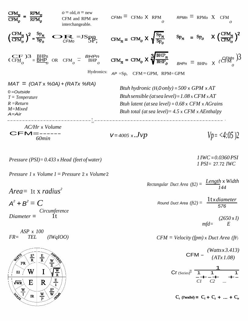
CF )3 BHPn _ BHPn
0 0 0 0
5P;
)3
=
o = old, n = new
CFM and RPM are
interchangeable.
CFMn = CFMo X RPM 0
RPMn = RPMo X CFM 0
OR =JSpn CFMo
( CFM = BHP OR CFM - BHP
Hydronics:
MAT = (OAT x %0A) + (RATx %RA)
0 =Outside
T = Temperature
BHPn = BHPo X
AP =Sp, CFM = GPM, RPM= GPM
Btuh hydronic (H20 only) = 500 x GPM x AT
Btuh sensible (at sea level) = 1.08 x CFM x AT
CFMn ( CFM
0
R =Return M=Mixed A=Air
Btuh latent (at sea level) = 0.68 x CFM x AGrains
Btuh total (at sea level)= 4.5 x CFM x AEnthalpy
----------------------------L-------------------------------------------·
AC/Hr x Volume
CFM=------ 60min
Pressure (PSI)= 0.433 x Head (feet of water)
Pressure 1 x Volume 1 = Pressure 2 x Volume 2
v = 4005 x .Jvp Vp = <4:05 )2
1 IWC = 0.0360 PSI 1 PSI= 27.72 IWC
Area= 1t x radius2
A2 + B
2 = C Circumference
Diameter = 1t
Rectangular Duct Area (ft2) =
Round Duct Area (ft2) =
Length x Width 144
1t x diameter
576
(2650 x I)
ASP x 100 FR= TEL (IWqIOO)
mfd= E
CFM = Velocity (fpm) x Duct Area (ft2)
CFM - (Watts x 3.413)
{ATx 1.08)
1 Cr (Series) 1 1 1
-+-+ +- C1 C2 ...
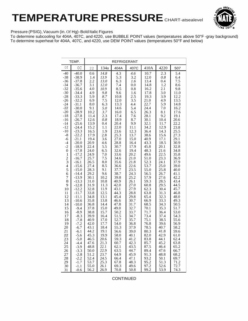
TEMPERATURE PRESSURE CHART-atsealevel
Pressure (PSIG), Vacuum (in. Of Hg)- Bold Italic Figures To determine subcooling for 404A, 407C, and 4220, use BUBBLE POINT values (temperatures above 50°F -gray background) To determine superheat for 404A, 407C, and 4220, use DEW POINT values (temperatures 50°F and below)
TEMP. REFRIGERANT
Of oc 22 134a 404A 407C 410A 4220 507
-40 -38 -36 -34 -32 -30 -28 -26 -24 -22 -20 -18 -16 -14 -12 -10 -8 -6 -4 -2 0 1 2 3 4 5 6 7 8 9
10 11 12 13 14 15 16 17 18 19 20 21 22 23 24 25 26 27 28 29 30 31
-40.0 -38.9 -37.8 -36.7 -35.6 -34.4 -33.3 -32.2 -31.1 -30.0 -28.9 -27.8 -26.7 -25.6 -24.4 -23.3 -22.2 -21.1 -20.0 -18.9 -17.8 -17.2 -16.7 -16.1 -15.6 -15.0 -14.4 -13.9 -13.3 -12.8 -12.2 -11.7 -11.1 -10.6 -10.0 -9.4 -8.9 -8.3 -7.8 -7.2 -6.7 -6.1 -5.6 -5.0 -4.4 -3.9 -3.3 -2.8 -2.2 -1.7 -1.1 -0.6
0.6 1.4 2.2 3.1 4.0 4.9 5.9 6.9 8.0 9.1
10.2 11.4 12.6 13.9 15.2 16.5 17.9 19.4 20.9 22.4 24.0 24.9 25.7 26.5 27.4 28.3 29.2 30.1 31.0 31.9 32.8 33.8 34.8 35.8 36.8 37.8 38.8 39.9 40.9 42.0 43.1 44.2 45.3 46.5 47.6 48.8 50.0 51.2 52.4 53.7 55.0 56.2
14.8 13.9 13.0 12.0 10.9 9.8 8.7 7.5 6.3 5.0 3.7 2.3 0.8 0.4 1.1 1.9 2.8 3.6 4.6 5.5 6.5 7.0 7.5 8.0 8.5 9.1 9.6
10.2 10.8 11.3 11.9 12.5 13.1 13.8 14.4 15.0 15.7 16.4 17.0 17.7 18.4 19.1 19.9 20.6 21.3 22.1 22.9 23.7 24.5 25.3 26.1 26.9
4.3 5.3 6.3 7.4 8.5 9.6
10.8 12.0 13.3 14.6 16.0 17.4 18.9 20.4 22.0 23.6 25.3 27.0 28.8 30.7 32.6 33.6 34.6 35.6 36.6 37.7 38.7 39.8 40.9 42.0 43.1 44.3 45.4 46.6 47.8 49.0 50.2 51.5 52.7 54.0 55.3 56.6 58.0 59.3 60.7 62.1 63.5 64.9 66.4 67.8 69.3 70.8
4.6 3.2 1.6 0.0 0.8 1.6 2.5 3.5 4.4 5.4 6.5 7.6 8.7 9.9
11.1 12.3 13.7 15.0 16.4 17.9 19.4 20.2 21.0 21.8 22.6 23.5 24.3 25.2 26.1 27.0 27.9 28.8 29.8 30.7 31.7 32.7 33.7 34.7 35.7 36.8 37.9 39.0 40.1 41.2 42.3 43.5 44.7 45.9 47.1 48.3 49.6 50.8
10.7 12.0 13.4 14.8 16.2 17.8 19.3 21.0 22.7 24.4 26.3 28.1 30.1 32.1 34.2 36.4 38.6 40.9 43.3 45.8 48.3 49.6 51.0 52.3 53.7 55.0 56.5 57.9 59.3 60.8 62.3 63.8 65.4 66.9 68.5 70.1 71.7 73.4 75.1 76.8 78.5 80.3 82.0 83.8 85.7 87.5 89.4 91.3 93.2 95.2 97.2 99.2
2.3 0.8 0.4 1.2 2.1 3.0 3.9 4.9 5.9 7.0 8.1 9.2
10.4 11.7 12.9 14.3 15.6 17.1 18.5 20.1 21.6 22.5 23.3 24.1 25.0 25.8 26.7 27.6 28.5 29.5 30.4 31.3 32.3 33.3 34.3 35.3 36.4 37.4 38.5 39.6 40.7 41.8 42.9 44.1 45.2 46.4 47.6 48.8 50.1 51.3 52.6 53.9
5.4 6.4 7.5 8.6 9.8
11.0 12.2 13.5 14.8 16.2 17.6 19.1 20.6 22.2 23.8 25.5 27.3 29.1 30.9 32.8 34.8 35.8 36.9 37.9 39.0 40.0 41.1 42.2 43.4 44.5 45.7 46.8 48.0 49.3 50.5 51.7 53.0 54.3 55.6 56.9 58.2 59.6 61.0 62.4 63.8 65.2 66.7 68.2 69.7 71.2 72.7 74.3
CONTINUED

TEMPERATURE PRESSURE CHART-atsealevel
Pressure (PSIG), Vacuum (in. Of Hg)- Bold Italic Figures To determine subcooling for 404A, 407C, and 4220, use BUBBLE POINT values (temperatures above 50°F -gray background) To determine superheat for 404A, 407C, and 4220, use DEW POINT values (temperatures 50°F and below)
TEMP. REFRIGERANT
•f oc 22 134a 404A 407C 410A 4220 507
32 0.0 57.5 27.8 72.4 52.1 101.2 55.2 75.8 33 0.6 58.8 28.6 73.9 53.4 103.3 56.5 77.4 34 1.1 60.2 29.5 75.5 54.8 105.4 57.9 79.0 35 1.7 61.5 30.4 77.1 56.1 107.5 59.3 80.7 36 2.2 62.9 31.3 78.7 57.5 109.7 60.6 82.3 37 2.8 64.3 32.2 80.3 58.9 111.9 62.0 84.0 38 3.3 65.7 33.1 82.0 60.3 114.1 63.5 85.7 39 3.9 67.1 34.1 83.7 61.7 116.3 64.9 87.5 40 4.4 68.6 35.0 85.4 63.2 118.6 66.4 89.2 42 5.6 71.5 37.0 88.8 66.1 123.2 69.4 92.8 44 6.7 74.5 39.0 92.4 69.2 127.9 72.5 96.4 46 7.8 77.6 41.1 96.0 72.3 132.8 75.6 100.2 48 8.9 80.8 43.2 99.8 75.5 137.8 78.9 104.0 50 10.0 84.1 45.4 103.6 78.8 142.9 82.2 108.0 52 11.1 87.4 47.7 109.2 101.7 148.1 96.1 112.0 54 12.2 90.8 50.0 113.3 105.6 153.5 99.8 116.1 56 13.3 94.4 52.4 117.4 109.6 159.0 103.6 120.4 58 14.4 98.0 54.9 121.7 113.7 164.7 107.4 124.7 60 15.6 101.6 57.4 126.0 117.9 170.4 111.4 129.1 62 16.7 105.4 60.0 130.5 122.3 176.3 115.4 133.7 64 17.8 109.3 62.7 135.0 126.7 182.4 119.5 138.3 66 18.9 113.2 65.4 139.7 131.2 188.6 123.8 143.1 68 20.0 117.3 68.2 144.4 135.8 194.9 128.1 147.9 70 21.1 121.4 71.1 149.3 140.5 201.4 132.5 152.9 72 22.2 125.7 74.1 154.3 145.4 208.0 137.1 158.0 74 23.3 130.0 77.1 159.4 150.3 214.8 141.7 163.2 76 24.4 134.5 80.2 164.6 155.4 221.8 146.5 168.5 78 25.6 139.0 83.4 169.9 160.5 228.9 151.3 174.0 80 26.7 143.6 86.7 175.4 185.8 236.1 156.3 179.5 82 27.8 148.4 90.0 181.0 171.2 243.6 161.3 185.2 84 28.9 153.2 93.5 186.7 176.8 251.2 166.5 191.0 86 30.0 158.2 97.0 192.5 182.4 258.9 171.8 197.0 88 31.1 163.2 100.6 198.4 188.2 266.8 177.2 203.0 90 32.2 168.4 104.3 204.5 194.1 274.9 182.7 209.2 92 33.3 173.7 108.1 210.7 200.1 283.2 188.4 215.5 94 34.4 179.1 112.0 217.0 206.3 291.6 194.1 222.0 96 35.6 184.6 115.9 223.4 212.5 300.3 200.0 228.6 98 36.7 190.2 120.0 230.0 219.0 309.1 206.0 235.3
100 37.8 195.9 124.2 236.8 225.5 318.1 212.1 242.2 102 38.9 201.8 128.4 243.6 232.2 327.2 218.4 249.2 104 40.0 207.7 132.7 250.8 239.0 336.6 224.8 256.3 106 41.1 213.8 137.2 257.8 245.9 346.2 231.3 263.7 108 42.2 220.0 141.7 265.1 253.0 355.9 237.9 271.1 110 43.3 226.4 146.4 272.5 260.3 365.9 244.7 278.7 112 44.4 232.8 151.1 280.1 287.6 376.1 251.6 286.5 114 45.6 239.4 156.0 287.9 275.1 386.4 258.8 294.4 116 46.7 246.1 160.9 295.8 282.8 397.0 265.8 302.4 118 47.8 253.0 166.0 303.8 290.6 407.8 273.2 310.7 120 48.9 260.0 171.2 312.1 298.6 418.8 280.6 319.1 125 51.7 278.0 184.6 333.3 319.2 447.4 299.9 340.8 130 54.4 296.9 198.7 355.6 340.7 477.4 320.2 363.6