air entrainment during impact of droplets on liquid...
TRANSCRIPT

J. Fluid Mech. (2013), vol. 726, R3, doi:10.1017/jfm.2013.261
Air entrainment during impact of droplets onliquid surfacesTuan Tran1,†, Hélène de Maleprade2, Chao Sun1,† and Detlef Lohse1,†
1Physics of Fluids Group, Faculty of Science and Technology, University of Twente,7500 AE Enschede, The Netherlands2Departement de Mecanique, Ecole Polytechnique, 91128 Palaiseau Cedex, France
(Received 18 March 2013; revised 18 March 2013; accepted 20 May 2013)
We study drop impact on a deep pool of the same fluid, with an emphasis on theair layer trapped under the droplets from its formation to its rupture. The penetrationvelocity of the air layer at a very short time scale prior to its rupture is shown,using an energy argument and experimental verification, to be one-half of the impactvelocity. We then deduce the dependence of the rupture position on the liquid viscosityand the impact velocity. We show that the volume of the resulting air bubbles canbe related to both those resulting from droplets impacting on solid surfaces and thoseresulting from rigid spheres impacting on liquid surfaces.
Key words: breakup/coalescence, drops and bubbles, thin films
1. Introduction
More than a hundred years after Worthington (1908) started to study droplet impactphenomena, the subject continues to attract researchers of various disciplines, not onlybecause of many fundamental questions originating from the phenomena involved,but also because of its importance in a wide range of technological applications, asreviewed by Prosperetti & Oguz (1993), Weiss & Yarin (1999) and Yarin (2006).The emphasis has been on bubble entrapment, bouncing, splashing, crown formationand droplet atomization. In the case of droplets impacting on liquid surfaces, ofparticular interest is the entrapment of an air layer, which may rupture and lead tothe entrainment of either a multitude of tiny bubbles (Mesler entrainment; see e.g.Esmailizadeh & Mesler 1986; Pumphrey & Elmore 1990) or only a few individualbubbles (see Thoroddsen, Etoh & Takehara 2003; Thoroddsen et al. 2012). Note thatthese bubble entrapment processes take place at very small time scales after impact, asopposed to that due to the collapse of the impact crater, which happens at much longer
† Email addresses for correspondence: [email protected], [email protected],[email protected]
c© Cambridge University Press 2013 726 R3-1

T. Tran, H. de Maleprade, C. Sun and D. Lohse
Liquid Viscosity, Density, Surface tension, Re= We=νl (cSt) ρ (kg m−3) σ (N m−1) RV/νl ρRV2/σ
5 cSt silicone oil 5 916 0.0197 96–177 11–3710 cSt silicone oil 10 934 0.0201 50–180 12–15820 cSt silicone oil 20 953 0.0208 24–106 11–217
TABLE 1. Properties of the silicone fluids used in the experiments and the correspondingranges of the Reynolds number and the Weber number.
time scales (see Pumphrey, Crum & Bjørnø 1989; Rein 1993). These findings, togetherwith the one reported by Xu, Zhang & Nagel (2005) that splashing can be completelysuppressed by reducing the ambient pressure, illustrate the complexity of the impactdynamics at early time scales and highlight the role of the air layer between the dropand the surface – for some recent investigations of the air layer, see, for example,Thoroddsen et al. (2005), Mandre, Mani & Brenner (2009), Mani, Mandre & Brenner(2010), Hicks & Purvis (2010, 2011), Duchemin & Josserand (2011), Bouwhuis et al.(2012), Hicks et al. (2012), Kolinski et al. (2012), Lee et al. (2012), Mandre &Brenner (2012), Tran et al. (2012), van der Veen et al. (2012) and Liu, Tan & Xu(2013).
The goal of this study is to focus on the dynamics of droplets impacting on adeep liquid pool of the same liquid, in particular the very beginning of the processwhen the two liquid surfaces start being deformed due to the pressure build-up. Thisdeformation entrains an air layer into the pool, which later ruptures to create airbubbles. We investigate the penetration velocity and thinning of the air film under thedrop. We also study the rupture process, and the resulting entrapped air bubbles, andrelate the volume of the entrapped air to that in the case of liquid droplets impactingon solid surfaces and in the case of solid spheres impacting on liquid surfaces.
2. Experimental details
In figure 1(a), we show a schematic of our experimental set-up used to study theimpact of droplets on a liquid pool. The thickness of the pool is roughly 10 mm,which can be considered as the deep pool limit. Droplets of uniform size (radiusR≈ 0.95 mm) are generated by pushing liquid out of a fine needle (24-gauge stainless-steel needle, Hamilton Co.) at a low rate (≈0.05 ml min−1). A droplet falls underits own weight onto a pool of the same liquid. The impact velocity V of the dropis varied between 0.3 and 2.3 m s−1 by adjusting the needle’s height. Both the dropradius R and velocity V in each experiment are measured before the impact time bya high-speed camera (Photron 1024 PCI) from the side. The working liquid in ourexperiments are silicone oils with viscosity νl = 5, 10 and 20 cSt. We choose siliconeoils as working fluids because it has been shown by Saylor & Bounds (2012) that theprocess of formation and subsequent rupture of the air layer is more repeatable forsilicone oils than for water. The exact properties of these fluids are listed in table 1.
We record the impacting process from the side and the bottom by two synchronoushigh-speed cameras (Photron SA1.1 and SA2 for the side- and bottom-view recordings,respectively) with frame rates up to 40 000 frames per second. The side-view camera(camera S in figure 1a) is slightly tilted upwards (with an angle ≈ 2) to look atthe impacting point from underneath the liquid. We use a long working distance
726 R3-2

Air entrainment during impact of droplets
S
B
Whitelight
g V
2R
Focusing point
Focusing point of bottom camera (B)
Free surface
DcL
1 mm
0.1 mm
Bubbles
Bubbles
Rupture points
–5.3 ms –3.6 ms –1.8 ms
0 ms 0.38 ms 1.3 ms
Half mirror
(c)
(b)(a)
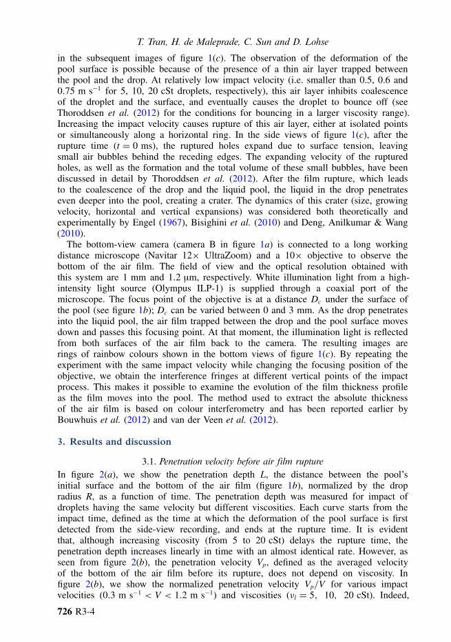
FIGURE 1. (a) Schematic (not to scale) of the experimental set-up used to observe the impactof droplets on a deep pool of the same liquid. (b) Schematic (not to scale) of the air film layeras the drop penetrates into the pool. The distance between the initial surface of the pool and thebottom of the air film is denoted L. The bottom camera is focused at a distance Dc under thefree surface of the pool. When the air film passes the focusing point of the camera (L = Dc),the bottom camera records interference fringes caused by light reflected from the two surfacesof the air film. (c) Series of representative images recorded from the side-view and bottom-viewcameras.
microscope (Navitar 12× UltraZoom) and a 1.5× objective to obtain an opticalresolution 4.2 µm.
In figure 1(c), we show a series of representative images of the impact taken fromthe side and from the bottom. We take the reference time (t = 0) as the time at whichthe film rupture is first detected from the side-view recording (see figure 1c). Thedeformation of the pool surface is due to the air pressure build-up between the pooland the drop (see figure 1b), and takes the shape of a growing spherical cap, as shown
726 R3-3
T. Tran, H. de Maleprade, C. Sun and D. Lohse
in the subsequent images of figure 1(c). The observation of the deformation of thepool surface is possible because of the presence of a thin air layer trapped betweenthe pool and the drop. At relatively low impact velocity (i.e. smaller than 0.5, 0.6 and0.75 m s−1 for 5, 10, 20 cSt droplets, respectively), this air layer inhibits coalescenceof the droplet and the surface, and eventually causes the droplet to bounce off (seeThoroddsen et al. (2012) for the conditions for bouncing in a larger viscosity range).Increasing the impact velocity causes rupture of this air layer, either at isolated pointsor simultaneously along a horizontal ring. In the side views of figure 1(c), after therupture time (t = 0 ms), the ruptured holes expand due to surface tension, leavingsmall air bubbles behind the receding edges. The expanding velocity of the rupturedholes, as well as the formation and the total volume of these small bubbles, have beendiscussed in detail by Thoroddsen et al. (2012). After the film rupture, which leadsto the coalescence of the drop and the liquid pool, the liquid in the drop penetrateseven deeper into the pool, creating a crater. The dynamics of this crater (size, growingvelocity, horizontal and vertical expansions) was considered both theoretically andexperimentally by Engel (1967), Bisighini et al. (2010) and Deng, Anilkumar & Wang(2010).
The bottom-view camera (camera B in figure 1a) is connected to a long workingdistance microscope (Navitar 12× UltraZoom) and a 10× objective to observe thebottom of the air film. The field of view and the optical resolution obtained withthis system are 1 mm and 1.2 µm, respectively. White illumination light from a high-intensity light source (Olympus ILP-1) is supplied through a coaxial port of themicroscope. The focus point of the objective is at a distance Dc under the surface ofthe pool (see figure 1b); Dc can be varied between 0 and 3 mm. As the drop penetratesinto the liquid pool, the air film trapped between the drop and the pool surface movesdown and passes this focusing point. At that moment, the illumination light is reflectedfrom both surfaces of the air film back to the camera. The resulting images arerings of rainbow colours shown in the bottom views of figure 1(c). By repeating theexperiment with the same impact velocity while changing the focusing position of theobjective, we obtain the interference fringes at different vertical points of the impactprocess. This makes it possible to examine the evolution of the film thickness profileas the film moves into the pool. The method used to extract the absolute thicknessof the air film is based on colour interferometry and has been reported earlier byBouwhuis et al. (2012) and van der Veen et al. (2012).
3. Results and discussion
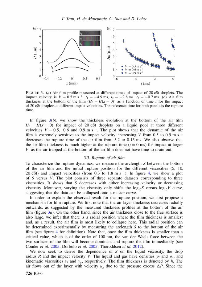
3.1. Penetration velocity before air film ruptureIn figure 2(a), we show the penetration depth L, the distance between the pool’sinitial surface and the bottom of the air film (figure 1b), normalized by the dropradius R, as a function of time. The penetration depth was measured for impact ofdroplets having the same velocity but different viscosities. Each curve starts from theimpact time, defined as the time at which the deformation of the pool surface is firstdetected from the side-view recording, and ends at the rupture time. It is evidentthat, although increasing viscosity (from 5 to 20 cSt) delays the rupture time, thepenetration depth increases linearly in time with an almost identical rate. However, asseen from figure 2(b), the penetration velocity Vp, defined as the averaged velocityof the bottom of the air film before its rupture, does not depend on viscosity. Infigure 2(b), we show the normalized penetration velocity Vp/V for various impactvelocities (0.3 m s−1 < V < 1.2 m s−1) and viscosities (νl = 5, 10, 20 cSt). Indeed,
726 R3-4

Air entrainment during impact of droplets
L
0.2
0.4
0.6
0.8
1.0
–3 –2 –1
0.5
0.4 0.6 0.8 1.00
1.2
0
1.0
t (ms)–4 0
V (m s–1)0.2 1.2
5 cSt10 cSt20 cSt
(a) (b)
FIGURE 2. (a) Penetration depth L normalized by the drop radius R as a function of time ofimpact of droplets of the same impact velocity (V = 0.55 m s−1) but different viscosities asshown in the legend. The rupture time of the air film is taken as the reference time (t = 0).(b) Normalized penetration velocity Vp/V for various impact velocities and viscosities.
the penetration velocity is found to be weakly dependent on the liquid viscosity (up tothe maximum viscosity used in our experiment) and about Vp ≈ V/2. This penetrationvelocity can be understood from an energy argument. First, let us consider a liquidvolume Ω at the bottom of the drop. This volume has the shape of a spherical capand velocity V . Thus, the initial kinetic energy of Ω before impact is E0
Ω = ρlΩV2/2.The same volume of liquid at a small time t after the impact time is then assumed tohave velocity Vp and takes the shape of a hemisphere of radius Rp, i.e. Ω = 2πR3
p/3.The kinetic energy of Ω at t is Et
Ω ≈ ρlΩV2p/2. Assuming that the velocity field in the
pool at time t is approximately a radial flow field with a point source at the centreof the hemisphere, we may estimate the kinetic energy of the liquid in the pool attime t as Et
P ≈ πρlR3pV2
p = 3ρlΩV2p/2. From the conservation of energy, E0
Ω = EtΩ + Et
P,we indeed obtain Vp ≈ V/2. Note that this result can alternatively be obtained byusing conservation of momentum and has been known in the context of penetrationmechanics (see e.g. Birkhoff et al. 1948; Yarin, Rubin & Roisman 1995). From thismodel, we also infer that it is possible to change the penetration velocity by usingliquids of different densities for the drop and for the pool. This speculation, however,is beyond the scope of the present study and needs further experimental verification.
3.2. Thinning of air film
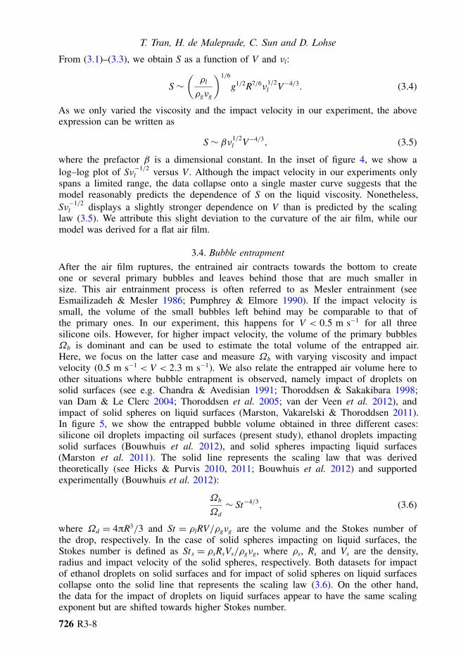
If figure 3(a), we show several profiles of the air film thickness of experiments withthe same impact conditions (νl = 20 cSt and V = 0.5 m s−1); each profile is extractedfrom an interference fringe obtained at a distinct focusing distance Dc (see figure 1b).This allows us to reconstruct the change in the air thickness profile as it moves intothe liquid pool. Here we assume that the air thickness profile at a fixed distance underthe pool’s surface does not change for repeated experiments with the same impactconditions since the impact dynamics are highly reproducible. Indeed, we have verifiedthe good reproducibility (using side-view recording) of the experiments. In particular,it takes the same time interval after the impact time for the film to rupture. As a result,repetition of the experiment with varying Dc provides the evolution of the thicknessprofile at the bottom of the air film.
726 R3-5
T. Tran, H. de Maleprade, C. Sun and D. Lohse
1
2
3
4
5
6
1
2
3
4
5
6
t (ms)–0.2 0 0.2
x (mm)–0.4 0.4
t1t2t3
–4 –2 0–60
7
0
7(a) (b)
t1t2t3
FIGURE 3. (a) Air film profile measured at different times of impact of 20 cSt droplets. Theimpact velocity is V = 0.5 m s−1, t1 = −4.9 ms, t2 = −2.8 ms, t3 = −0.7 ms. (b) Air filmthickness at the bottom of the film (H0 = H(x = 0)) as a function of time t for the impactof 20 cSt droplets at different impact velocities. The reference time for both panels is the rupturetime.
In figure 3(b), we show the thickness evolution at the bottom of the air filmH0 = H(x = 0) for impact of 20 cSt droplets on a liquid pool at three differentvelocities V = 0.5, 0.6 and 0.9 m s−1. The plot shows that the dynamic of the airfilm is extremely sensitive to the impact velocity: increasing V from 0.5 to 0.9 m s−1
decreases the rupture time of the air film from 5.2 to 0.15 ms. We also observe thatthe air film thickness is much higher at the rupture time (t = 0 ms) for impact at largerV , as the air trapped at the bottom of the air film does not have time to drain out.
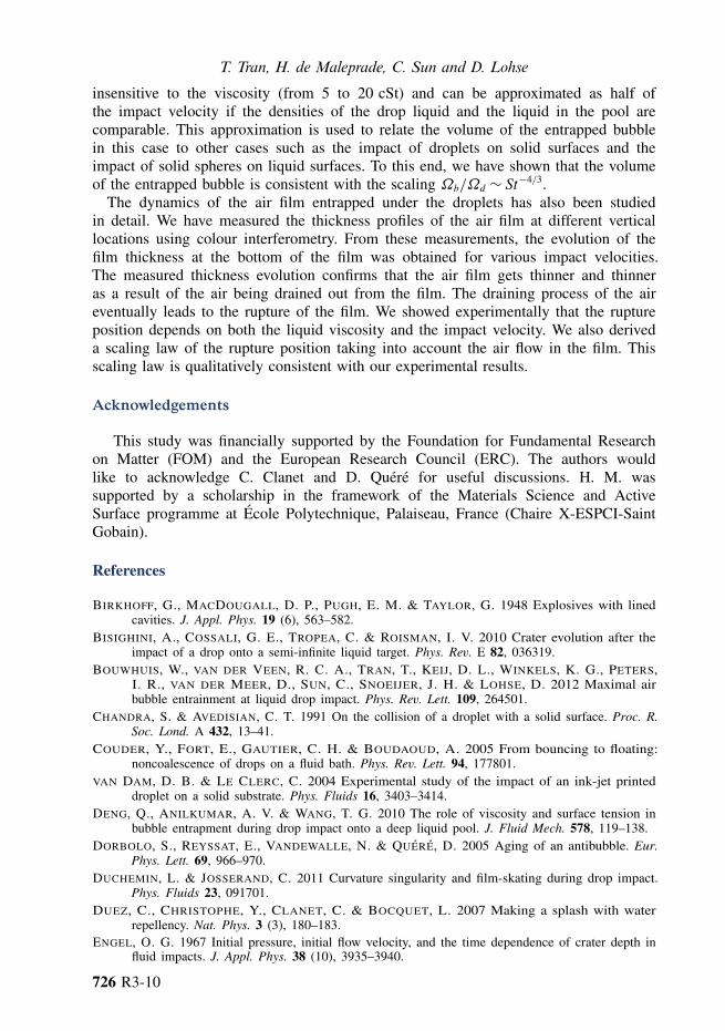
3.3. Rupture of air filmTo characterize the rupture dynamics, we measure the arclength S between the bottomof the air film and the initial rupture position for the different viscosities (5, 10,20 cSt) and impact velocities (from 0.3 to 1.8 m s−1). In figure 4, we show a plotof S versus V . The plot consists of three separate datasets corresponding to threeviscosities. It shows that S decreases with either increasing velocity or decreasingviscosity. Moreover, varying the viscosity only shifts the log10S versus log10V curve,suggesting that the data can be collapsed onto a master curve.
In order to explain the observed result for the rupture position, we first propose amechanism for film rupture. We first note that the air layer thickness decreases radiallyoutwards, as suggested by the measured thickness profiles at the bottom of the airfilm (figure 3a). On the other hand, since the air thickness close to the free surface isalso large, we infer that there is a radial position where the film thickness is smallestand, as a result, the air film is most likely to collapse here. This radial position canbe determined experimentally by measuring the arclength S to the bottom of the airfilm (see figure 4 for definition). Note that, once the film thickness is smaller than acritical value, which is of the order of 100 nm, the van der Waals force between thetwo surfaces of the film will become dominant and rupture the film immediately (seeCouder et al. 2005; Dorbolo et al. 2005; Thoroddsen et al. 2012).
We now seek to derive the dependence of S on the liquid viscosity, the dropradius R and the impact velocity V . The liquid and gas have densities ρl and ρg, andkinematic viscosities νl and νg, respectively. The film thickness is denoted by h. Theair flows out of the layer with velocity ug due to the pressure excess 1P. Since the
726 R3-6

Air entrainment during impact of droplets
S
log10V (m s–1)
log 1
0S
(mm
)
log10V (m s–1)
0
–1
0–0.5
–1
0
–0.5 0
5 cSt10 cSt20 cSt
FIGURE 4. Log–log plot of the rupture position S as a function of impact velocity for differentviscosities. Inset: log–log plot of Sν−1/2
l as a function of impact velocity. The solid linerepresents the exponent −4/3 of the scaling law (3.5).
impact velocity is relatively low, we take the hydrostatic pressure 1P ∼ ρlgR, whereg is the gravitational acceleration. Because S was shown to depend on the liquidviscosity, we cannot treat the liquid–air interfaces as rigid surfaces. Instead, we assumecontinuity of the shear stress across the interface. Hence, the shear stress in the gaslayer, τg ∼ ρgνgug/h, is balanced with the shear stress in the liquid, τl ∼ ρlνlug/δ,where δ ∼√νlS/ug is the thickness of the boundary layer in the liquid. This gives usan estimate for the gas velocity:
ug ∼ρ2
g
ρ2l
ν2g S
νlh2. (3.1)
Typically, S ≈ 1 mm and h ≈ 1 µm in our experiments. From these values, (3.1) givesus the estimate for the gas velocity ug ≈ 4 cm s−1. This is comparable to the velocityof gas exiting the gap between an impacting droplet and a solid surface measured invan der Veen et al. (2012).
Next, for the gas flow in the gap, we assume the lubrication approximation:
1P
S∼ ρgνg
ug
h2. (3.2)
To estimate h, we use the initial air gap at the impact time, which is similar to theinitial air gap for impact on a solid surface (Bouwhuis et al. 2012):
h∼ R
(ρgνg
ρlVR
)2/3
. (3.3)
726 R3-7
T. Tran, H. de Maleprade, C. Sun and D. Lohse
From (3.1)–(3.3), we obtain S as a function of V and νl:
S∼(ρl
ρgνg
)1/6
g1/2R7/6ν1/2l V−4/3. (3.4)
As we only varied the viscosity and the impact velocity in our experiment, the aboveexpression can be written as
S∼ βν1/2l V−4/3, (3.5)
where the prefactor β is a dimensional constant. In the inset of figure 4, we show alog–log plot of Sν−1/2
l versus V . Although the impact velocity in our experiments onlyspans a limited range, the data collapse onto a single master curve suggests that themodel reasonably predicts the dependence of S on the liquid viscosity. Nonetheless,Sν−1/2
l displays a slightly stronger dependence on V than is predicted by the scalinglaw (3.5). We attribute this slight deviation to the curvature of the air film, while ourmodel was derived for a flat air film.
3.4. Bubble entrapmentAfter the air film ruptures, the entrained air contracts towards the bottom to createone or several primary bubbles and leaves behind those that are much smaller insize. This air entrainment process is often referred to as Mesler entrainment (seeEsmailizadeh & Mesler 1986; Pumphrey & Elmore 1990). If the impact velocity issmall, the volume of the small bubbles left behind may be comparable to that ofthe primary ones. In our experiment, this happens for V < 0.5 m s−1 for all threesilicone oils. However, for higher impact velocity, the volume of the primary bubblesΩb is dominant and can be used to estimate the total volume of the entrapped air.Here, we focus on the latter case and measure Ωb with varying viscosity and impactvelocity (0.5 m s−1 < V < 2.3 m s−1). We also relate the entrapped air volume here toother situations where bubble entrapment is observed, namely impact of droplets onsolid surfaces (see e.g. Chandra & Avedisian 1991; Thoroddsen & Sakakibara 1998;van Dam & Le Clerc 2004; Thoroddsen et al. 2005; van der Veen et al. 2012), andimpact of solid spheres on liquid surfaces (Marston, Vakarelski & Thoroddsen 2011).In figure 5, we show the entrapped bubble volume obtained in three different cases:silicone oil droplets impacting oil surfaces (present study), ethanol droplets impactingsolid surfaces (Bouwhuis et al. 2012), and solid spheres impacting liquid surfaces(Marston et al. 2011). The solid line represents the scaling law that was derivedtheoretically (see Hicks & Purvis 2010, 2011; Bouwhuis et al. 2012) and supportedexperimentally (Bouwhuis et al. 2012):
Ωb
Ωd∼ St−4/3, (3.6)
where Ωd = 4πR3/3 and St = ρlRV/ρgνg are the volume and the Stokes number ofthe drop, respectively. In the case of solid spheres impacting on liquid surfaces, theStokes number is defined as St s = ρsRsVs/ρgνg, where ρs, Rs and Vs are the density,radius and impact velocity of the solid spheres, respectively. Both datasets for impactof ethanol droplets on solid surfaces and for impact of solid spheres on liquid surfacescollapse onto the solid line that represents the scaling law (3.6). On the other hand,the data for the impact of droplets on liquid surfaces appear to have the same scalingexponent but are shifted towards higher Stokes number.
726 R3-8

Air entrainment during impact of droplets
5 cSt silicone oil droplet on 5 cSt oil surface10 cSt silicone oil droplet on 10 cSt oil surface20 cSt silicone oil droplet on 20 cSt oil surface15 mm steel sphere on water (Marston et al. 2011)20 mm steel sphere on 10 cSt oil (Marston et al. 2011)20 mm steel sphere on 25 cSt oil (Marston et al. 2011)20 mm steel sphere on 1 cSt SDS (Marston et al. 2011)Ethanol droplet on solid surface (Bouwhuis et al. 2012)
Drop on pool
Sphere on pool
Drop on solidsurface
log10 St
–6
–5
–4
4 5 6
–6
–5
–4
5log10 St
4 6
FIGURE 5. Log–log plot of the normalized bubble volume Ωb/Ωd as a function of Stokesnumber in three cases sketched on the right-hand side: impact of droplets on liquid surfaces(present study); impact of solid spheres on liquid surfaces (Marston et al. 2011) (SDS = sodiumdodecyl sulfate); and impact of droplets on solid surfaces (Bouwhuis et al. 2012). The solid linerepresents the −4/3 scaling law presented in (3.6). Inset: collapse of the dataset for impact ofdroplets on liquid surfaces on other datasets after using the Stokes number calculated using thepenetration velocity of the air film layer.
To understand this result, let us first consider the impact of droplets on liquidsurfaces. In this case, the two approaching surfaces (of the droplet and the liquidpool) are both deformable; the air film penetrates into the liquid pool with velocityVp ≈ V/2. In contrast, for the impact of solid spheres on liquid surfaces, or the impactof droplets on solid surfaces, only one of the approaching surfaces is deformable.In these cases, the air film moves into the liquid bulk with the impact velocity.This observation prompts us to use Vp instead of V as the relevant velocity tocalculate the Stokes number for the case of two deformable surfaces. In the insetof figure 5, we show the bubble volume for all cases, with the modified Stokesnumber St = ρlRVp/ρgνg for the case of droplets impacting liquid pools. The datasetfor impacts of droplets on liquid surfaces indeed now collapses onto the same lineas the other two sets of data and is consistent with the scaling law (3.6). Note thatthe solid surfaces for all of these datasets are hydrophilic. In the case that the solidsurfaces are hydrophobic, it is possible that the normalized bubble volume dependsdifferently on the Stokes number, as the air entrapment mechanism may be different.This has not been tested, but is deduced from the related experiments by Duez et al.(2007) in which the splash occurrence is influenced by the wettability of the surface.
4. Conclusions
We have described the impact dynamics, including the penetration velocity Vp ofthe air film entrapped between the drop and the pool surface. We showed that Vp is
726 R3-9
T. Tran, H. de Maleprade, C. Sun and D. Lohse
insensitive to the viscosity (from 5 to 20 cSt) and can be approximated as half ofthe impact velocity if the densities of the drop liquid and the liquid in the pool arecomparable. This approximation is used to relate the volume of the entrapped bubblein this case to other cases such as the impact of droplets on solid surfaces and theimpact of solid spheres on liquid surfaces. To this end, we have shown that the volumeof the entrapped bubble is consistent with the scaling Ωb/Ωd ∼ St−4/3.
The dynamics of the air film entrapped under the droplets has also been studiedin detail. We have measured the thickness profiles of the air film at different verticallocations using colour interferometry. From these measurements, the evolution of thefilm thickness at the bottom of the film was obtained for various impact velocities.The measured thickness evolution confirms that the air film gets thinner and thinneras a result of the air being drained out from the film. The draining process of the aireventually leads to the rupture of the film. We showed experimentally that the ruptureposition depends on both the liquid viscosity and the impact velocity. We also deriveda scaling law of the rupture position taking into account the air flow in the film. Thisscaling law is qualitatively consistent with our experimental results.
Acknowledgements
This study was financially supported by the Foundation for Fundamental Researchon Matter (FOM) and the European Research Council (ERC). The authors wouldlike to acknowledge C. Clanet and D. Quere for useful discussions. H. M. wassupported by a scholarship in the framework of the Materials Science and ActiveSurface programme at Ecole Polytechnique, Palaiseau, France (Chaire X-ESPCI-SaintGobain).
References
BIRKHOFF, G., MACDOUGALL, D. P., PUGH, E. M. & TAYLOR, G. 1948 Explosives with linedcavities. J. Appl. Phys. 19 (6), 563–582.
BISIGHINI, A., COSSALI, G. E., TROPEA, C. & ROISMAN, I. V. 2010 Crater evolution after theimpact of a drop onto a semi-infinite liquid target. Phys. Rev. E 82, 036319.
BOUWHUIS, W., VAN DER VEEN, R. C. A., TRAN, T., KEIJ, D. L., WINKELS, K. G., PETERS,I. R., VAN DER MEER, D., SUN, C., SNOEIJER, J. H. & LOHSE, D. 2012 Maximal airbubble entrainment at liquid drop impact. Phys. Rev. Lett. 109, 264501.
CHANDRA, S. & AVEDISIAN, C. T. 1991 On the collision of a droplet with a solid surface. Proc. R.Soc. Lond. A 432, 13–41.
COUDER, Y., FORT, E., GAUTIER, C. H. & BOUDAOUD, A. 2005 From bouncing to floating:noncoalescence of drops on a fluid bath. Phys. Rev. Lett. 94, 177801.
VAN DAM, D. B. & LE CLERC, C. 2004 Experimental study of the impact of an ink-jet printeddroplet on a solid substrate. Phys. Fluids 16, 3403–3414.
DENG, Q., ANILKUMAR, A. V. & WANG, T. G. 2010 The role of viscosity and surface tension inbubble entrapment during drop impact onto a deep liquid pool. J. Fluid Mech. 578, 119–138.
DORBOLO, S., REYSSAT, E., VANDEWALLE, N. & QUERE, D. 2005 Aging of an antibubble. Eur.Phys. Lett. 69, 966–970.
DUCHEMIN, L. & JOSSERAND, C. 2011 Curvature singularity and film-skating during drop impact.Phys. Fluids 23, 091701.
DUEZ, C., CHRISTOPHE, Y., CLANET, C. & BOCQUET, L. 2007 Making a splash with waterrepellency. Nat. Phys. 3 (3), 180–183.
ENGEL, O. G. 1967 Initial pressure, initial flow velocity, and the time dependence of crater depth influid impacts. J. Appl. Phys. 38 (10), 3935–3940.
726 R3-10

Air entrainment during impact of droplets
ESMAILIZADEH, L. & MESLER, R. 1986 Bubble entrainment with drops. J. Colloid Interface Sci.110 (2), 561–574.
HICKS, P. D., ERMANYUK, E. V., GAVRILOV, N. V. & PURVIS, R. 2012 Air trapping at impact ofa rigid sphere onto a liquid. J. Fluid Mech. 695, 310–320.
HICKS, P. D. & PURVIS, R. 2010 Air cushioning and bubble entrapment in three-dimensionaldroplet impacts. J. Fluid Mech. 649, 135–163.
HICKS, P. D. & PURVIS, R. 2011 Air cushioning in droplet impacts with liquid layers and otherdroplets. Phys. Fluids 23, 062104.
KOLINSKI, J. M., RUBINSTEIN, S. M., MANDRE, S., BRENNER, M. P., WEITZ, D. A. &MAHADEVAN, L. 2012 Skating on a film of air: drops impacting on a surface. Phys. Rev.Lett. 108 (7), 074503.
LEE, J. S., WEON, B. M., JE, J. H. & FEZZAA, K. 2012 How does an air film evolve into abubble during drop impact? Phys. Rev. Lett. 109 (20), 204501.
LIU, Y., TAN, P. & XU, L. 2013 Compressible air entrapment in high-speed drop impacts on solidsurfaces. J. Fluid Mech. 716, doi:10.1017/jfm.2012.583.
MANDRE, S. & BRENNER, M. P. 2012 The mechanism of a splash on a dry solid surface. J. FluidMech. 690, 148–172.
MANDRE, S., MANI, M. & BRENNER, M. P. 2009 Precursors to splashing of liquid droplets on asolid surface. Phys. Rev. Lett. 102 (13), 134502.
MANI, M., MANDRE, S. & BRENNER, M. P. 2010 Events before droplet splashing on a solidsurface. J. Fluid Mech. 647, 163–185.
MARSTON, J. O., VAKARELSKI, I. U. & THORODDSEN, S. T. 2011 Bubble entrapment duringsphere impact onto quiescent liquid surfaces. J. Fluid Mech. 680 (1), 660–670.
PROSPERETTI, A. & OGUZ, H. N. 1993 The impact of drops on liquid surfaces and the underwaternoise of rain. Annu. Rev. Fluid Mech. 25 (1), 577–602.
PUMPHREY, H. C., CRUM, L. A. & BJØRNØ, L. 1989 Underwater sound produced by individualdrop impacts and rainfall. J. Acoust. Soc. Am. 85, 1518–1526.
PUMPHREY, H. C. & ELMORE, P. A. 1990 Entrainment of bubbles by drop impacts. J. Fluid Mech.220, 539–567.
REIN, M. 1993 Phenomena of liquid drop impact on solid and liquid surfaces. Fluid Dyn. Res. 12(2), 61–93.
SAYLOR, J. & BOUNDS, G. D. 2012 Experimental study of the role of the Weber and capillarynumbers on Mesler entrainment. AIChE J. 58 (12), 3841–3851.
THORODDSEN, S. T., ETOH, T. G. & TAKEHARA, K. 2003 Air entrapment under an impacting drop.J. Fluid Mech. 478, 125–134.
THORODDSEN, S. T., ETOH, T. G., TAKEHARA, K., OOTSUKA, N. & HATSUKI, Y. 2005 The airbubble entrapped under a drop impacting on a solid surface. J. Fluid Mech. 545, 203–212.
THORODDSEN, S. T. & SAKAKIBARA, J. 1998 Evolution of the fingering pattern of an impactingdrop. Phys. Fluids 10, 1359–1374.
THORODDSEN, S. T., THORAVAL, M. J., TAKEHARA, K. & ETOH, T. G. 2012 Micro-bubblemorphologies following drop impacts onto a pool surface. J. Fluid Mech. 708, 469–479.
TRAN, T., STAAT, H. J. J., PROSPERETTI, A., SUN, C. & LOHSE, D. 2012 Drop impact onsuperheated surfaces. Phys. Rev. Lett. 108 (3), 036101.
VAN DER VEEN, R. C. A., TRAN, T., LOHSE, D. & SUN, C. 2012 Direct measurements of airlayer profiles under impacting droplets using high-speed color interferometry. Phys. Rev. E 85(2), 026315.
WEISS, D. A. & YARIN, A. L. 1999 Single drop impact onto liquid films: neck distortion, jetting,tiny bubble entrainment, and crown formation. J. Fluid Mech. 385, 229–254.
WORTHINGTON, A. M. 1908 A Study of Splashes. Longmans, Green.XU, L., ZHANG, W. W. & NAGEL, S. R. 2005 Drop splashing on a dry smooth surface. Phys. Rev.
Lett. 94 (18), 184505.YARIN, A. L. 2006 Drop impact dynamics: splashing, spreading, receding, bouncing. Annu. Rev.
Fluid Mech. 38, 159–192.YARIN, A. L., RUBIN, M. B. & ROISMAN, I. V. 1995 Penetration of a rigid projectile into an
elastic–plastic target of finite thickness. Intl J. Impact Engng 16 (5), 801–831.
726 R3-11