air force r:. reliability and …reliability and maintainability information system (rexis)...
TRANSCRIPT

AFHRL-TF-87-37
AIR FORCE R:. RELIABILITY AND MAINTAINABILITY (R&M)
HRobert J. Hankins
U Integrated Support Systems, Inc.100 McCollum Street
M Clemson. South Carolina 29631
A LOGISTICS AND HUMAN FACTORS DIVISION
N Wright-Patterson Air Force Base, Ohio 45433-6503
00
R May 1988E Interim Technical Paper for Period March 1982 - May 1986
o( S0 Approved for public release; distribution is unlimited.
U DTICR %ELE-c-TE
C ~MA 4 19M8
ES LABORATORY
AIR FORCE SYSTEMS COMMANDBROOKS AIR FORCE BASE, TEXAS 78235-5601
C.','r'z" ;t

NOTICE
When Government drawings, specifications, or other data are used for anypurpose other than in connection with a definitely Government-relatedprocurement, the United States Government incurs no responsibility or anyobligation whatsoever. The fact that the Go*iernmnt may have formulated orin any way supplied the said drawings, specifications, or other data, isnot to be regarded by implication, or otherwise in any manner construed, aslicensing the holder, or any other person or corporation; or as conveyingany rights or permission to manufacture, use, or sell any patentedinvention that may in any way be related thereto.
The Public Affairs Office has reviewed this paper, and it Is releasable tothe National Technical Information Service, where it will be available tothe general public, including foreign nationals.
This paper has been reviewed and is approved for publication.
JOHN IANNI
Contract Monitor
BERTARM W. CREM4, Technical DirectorLogistics and Human Factors Division
DONALD C. TETNEYER, Colonel, USAFChief, Logistics and Human Factors Division
4L
_ "d:
4

U n c la s s if ie d0
" A v eS[CU?IrY CLASSIFICATION OF 11415 PICK
REPORT DOCUMENTATION PAGE 0118MoN. 0 10" IIF
To. AREPORT SECURITY CLASSIFICATION Ib. RESTRICTIVE MAIRKINGS
2a. SECURITY CLASSIFICATION AUTHORITY I OISTRIOUTIQN IAVAILASItTY OF REPORT2__.___________________________________SCHEDULE_ Approved for public release; distribution is unlimited.
4. PERFORMING ORGANIZATION REPOA1 NUMCER(S) S. MONITORING ORGANIZAtION REPORT NUMBER($)
rAVHML-TP487-37S I N OF PERFORMING ORGANtIZATIO OFF4CE SYMUOL 74. NAME OF MONITORING ORGANIZATION4
(if appIkubbeIntegrated Support Systaem, Inc. Logistics and Haaen Factors Division
&L. ADDRESS (City. Staft, "n ZIP Cof) lb. ADOR9SS CZW State. aind ZIP Coo
100 McCollmu Street Air Force IHzmmn Resources LaboratoryClason, South Carolina 29631 Wright-Patterson Air Force Base, Ohio 46433-6603
$a. NAME OF FUNDING /SPONSORING &b. OFFICE SYMBOL 9. PROCUREMENT INSTRUMENT IDENTIFICATION NUMBERAir Force Humian Resources Laboratory NO AFHRL F33615-WC-C0061
I.ADDRIESS (City, State, And ZIP Code) 10. SOURCE OF FUNDING NUMBERSWPROGRAM PROjECT TASK W ORK UNITBrooks Air Force Base, Texas 78231-5601 ELEMENT NO. NO. NO CCESSION NO0
6310UF 2940 04 0111. TITLE (include Security Cl.wftcerion)
(Reliability and Maintainability (RAN)
F12. PERSONAL AUTMOR(S)
111a. TYPE OF REPORT l13b. TIME COVERED 14d. DATE OF REPORT (Year, ~ftA Day) 11 S. PAGE COUNTInterim jFO J TJL IMay 1988 56
1'6. SUPPLEMENTARY NOTATION
1 IEL COSATI CODES 18. SUBJECT TERMS (Comwanue on reveno if meceue'y anid idmnti( by Nock tAumber)1 IE. GROUP SLJSGROUP logistics support analysis
05 asreliability, availability, and maintainability analysisreliability and maintainability Information system (REXIS) (Continued)
19. ABSTRACT (Coninu-o reverse if reconhry anid idenrufy by biock number)
~-This paper details an Air Force Reliability and Maintainability (R&M) study which investigated the degree towhich R&4 logistics analyses requirements are satisfied by the Unified Data Base (UDS) for LogisticsInformIation, a fully automated onqline interactive Logistic Support Analysis Record system. The R801 studyconsisted of three sequential tasks: (a) investigation and definition of requirements, (b) definition of thefrequency and method of specific RAM data collection, and (c) *performance of comparability analyses of data.elements defined in the first task and Currently in the UDS. This paper includes a detailed description of theprocedures folwdadrslso ahtask and provides recoamendations for incorporation Into the lIDB.
20 OISTRIBJT!ON iAVAILABILITY OF ABSTRACT 21 ABSTRACT SECURITY CLASSIFICATIONS o'NCLASWFIEO/UNUMITEO C3 SAME AS QPT C) OT USERS Unclassified~i cu e2 c F IE S M O224 NAME OF RESPONSIBLE INDIVIDUAL 22b. TELEPMONE (nld reCd)2c FIESMO
Nancy J. Allin, Chief, STINFO Office (1)536-3877 AFIHRL/TSR00 Form 1473, JUN 86 Previous editionuat@Obsolete. SECURITY CLASSIFICATION OF THIS5 PAGE

!tm 18 (Concluded):
reliabillty and maintainabilit~y trackingr~elitabilitty malasge1efitunified data base for logistics information
'I
x.h

AFIL Technical Paper 87-37 May 1988
RELIABILITY AND MAINTAINABILITY (RiN)
Robert J. Hankins
Integrated Support Systems, !nc.100 NcCollum Street 0
Clemson, South Carolina 29631
LOGISTICS AND HUMAN FACTO•S DIVISIONWright-Patterson Air Force Base, Ohio 45433-6503
i ~~~~~~Reviewe b~y....:. .. . ..
c+
Joseph W. Colemn, Lt Col, USAF
Chief, Acquisition Logistics Branch '
Submitted for publication by
Bertram W. Cream, Technical DirectorLogistics and Human Factors Division
--- * This publication is primarily a working paper. It Is published solely to document work performed.
- .. ~~~~~~~~eZ Ike I'' ~* - ~ . -'J . . *% . , *

SUMMARY
The present effort was designed to accomplish the followingtasks: (a) Investigate and define Reliability and Maintainability(R&M) analysis, documentation and tracking; (b) Define thefrequency and method of specific R&M data collection; (c) Performcomparability analysis of data elements defined in Task 1 anddata elements currently in the Unified Data Base (UDB 2000); and(d) Prepare a final report covering the results and findings ofeach task.
The investigation and definition of requirements in Task 1were accomplished through research of applicable directives andthrough personal contact with Offices of Primary Responsibility(OPRs). The results of this task are addressed in detail withexamples provided in the form of an R&M Program Audit Trail chartand a Reliability Management chart.
The frequency and method of specific R&M data collection(Task 2) are then discussed. Primarily, it was found that thefrequency of R&M data collection is acquisition programdependent, as is the requirement for the capability to assess theR&M program status. Reports on program status are required ondemand, as determined by Lhe acquisition program manager. Datacollection after fielding will be required in a near-real-timemode for the proposed Reliability and Maintainability InformationSystem (REMIS).
A comparison of the data elements required and the dataelements currently in the UDB 2000 was accomplished in Task 3.Results of this task show that although some of the elements arecurrently in the UDB 2000, they are not in the form nee~ded tosatisfy the requirements for tracking. The elementsfcurrently inUDB 2000 are not time/phase-related, as is necessary to satisfythe requirements identified in Task 1.
The authors identify additional data elements, screens, andreports that should be incorporated into UDB 2000. They.alsorecommend that an interface between UDB 2000 and REMIS beincorporated into the REMIS development effort. Finally, it isalso recommended that an Air Force policy decision on theretention, use, and method of storing Logistic Support AnalysisR Record (LSAR) data after fielding be obtained as soon as
S~ possible.
p s11
r C o

--- -- - - ' - - - ' - ' - ' - W -- P .- .ý .ý L'% ý -1 ' .WN V .b 't. ~V . W k d -- . . JV YVjS I' ^ "N W' 4- ý _04. JV ,
PREFACE
This work was initiated by the Logistics and Human Factors Division,Air Force Human Resources Laboratory, Wright-Patterson Air Force Base,Ohio, under Project 2940. The Work Unit was 2940-04-01, Unified DataBase (UDB) for Logistics Information.
Appreciation is extended to LTC Joseph W Coleman of the AcquisitionLogistics Branch of AFHRL for his guidance and encouragement throughoutthis effort. Appreciation is also extended to the many individuals ofAir Force Acquisition Logistics Center at Wright-Patterson Air ForceBase, Ohio, who supplied information in support of this study.
bII
±i

TABLE OF CONTENTS
Page
1.0 INTRODUCTION .......................................... 1
Background ........................................... I
Tasks To Be Performed ................................ 1Purpose .............................................. 2
2.0 TASK 1. INVESTIGATE AND DEFINE REQUIREMENTS ............. 2
Contractor Predictions/Allocations ................... 2R&H Tracking Requirements at the Program
Management Level .................... . . .... .... .. ... . . 3Continued Tracking After Fielding to Maturity .......... 4
3.0 TASK 2. DEFINE FREQUENCY AND METHOD OF R&M DATACOLLECTION, STORAGE, MANAGEMENT, AND RETRIEVAL ........ 5
Requirements For Assessment 5Data Storage, Management, and Retrieval.5
4.0 TASK 3. PERFORM COMPARABILITY ANALYSIS ................... 6
Data Elements Not Currently in UDB 2000................. 6Data Elements Required For Tracking .... ................ 6
5.0 RELIABILITY AND MAINTAINABILITY INFORMATIONSYSTEM (REMIS) ................................... 6
Interface ............................................ 6
6.0 CONCLUSIONS AND RECOMMENDATIONS ................. ....... 7
p Air Force Policy on Retention of LSAR Not Clear ...... 7InCerface With REMIS Needed ........ . ................... 8Areas To Be Tracked .................................. 8Contractor Tracking of Predictions
Versus Allocations ... ................................ 8-I Program Management ?racking ..... .. . ..... ........ 9
Operational System Tracking ........................... 9
APPENDIX A: R&M PROGRAM AUDIT TRAIL ............................. I 1, APPENDIX B: RELIABILITY MANAGEMENT CHART .... .................. 15
APPEND'X C: RELTABTLITY GROWTH AT THE COMONENT LEVEL ..... 13APPENDIX D: RELIABILITY GROWTH PROCEDURES.................. 3-APPENDIX E: R&M TRACKING SCREENS AND REPORT FORMATS ....... 3
'!• REFERENCES...............................................................4'?
GLOSSARY ............. ..................................................... 48
S--iii
'I.:

1 .0 INTRODUCTION
Background
The Department of Defense (DoD) is placing increasingemphasis on Reliability and Maintainability (R&M), due to theever-increasing costs associated vdith the operation and supportof new weapon systems. Consequently, procedures for monitoring"and tracking Reliability, Availability, and Maintainability (RAM)parameters were developed and published in AFR 800-18, Air ForceReliability and Maintainability Program, dated 15 June 1982.This regulation establishes Air Force policy relative to themanagement and control of an R&M Program for each weapon systemacquisition and major modification program. Independent reviewsof major defense system acquisition programs (see AFR 800-5) willbe made to assess the adequacy of the R&M program.
The present effort addresses the method of collecting,Sscoring, retrieving, and presenting the results of theseassessments throughout the life cycle of the system/equipment.The term R&M includes availability and readiness as defined inAPR 800-18. Air Force Logistics Command (AFLC) Supplement I to
=i APR 800-18, dated 10 May 1983, further defines the specificresponsibilities of AFLC with respect to R&M program managementduring the acquisition phase and after fielding of thesystem/equipment.
The results of a preliminary analysis were previouslysubmitted on 17 Hay 1985. Additional research and analysis wereconducted to verify the findings of the preliminary analysis andto expand the investigation to additional sources of information.
There is a need for R&M tracking in three distinctr reas.One is for the contractor's predictions in meeting the R&Mrequirements imposed by the Government agency procuring thesystem/equipment. The second is for program management duringdevelopment , and the third is continued tracking after fieldingof the system/equipment. In addition, there is a need to trackAvailability (A) as well as R&M. Therefore, this study addresses
", R&M and A (commonLy referred to as RAM parameters).
Tasks To Be Performed
The R&M Study con. n is ted of four sequent ial tasks asidentified below:
' Ta.3k 1 I nvestigate and de f i ne the req u i rement s for R&Manalysis, doc:umentation, and tracking throughout the weapon
% system development cycle, based on MTL-STD-1692A, MIL-STD-785MIL-STD-470, MIL-STD-1 388-IA, AFR 800-18. and other sources.
a.-•

I
offices of Primary Responsibility (OPRs) for the various
MIL-STDs will be contacted for the purpose of determining the
extent to which anticipated changes to the MIL-STDs would
impact the R&M community.
Task 2 - Define the frequency and method of specific R&M data
collection throughout the acquisition cycle of a weapon system.
Define the method of historical R&M data storage, data
management, and data retrieval. Define and justify specific
output reports and frequency of reports required throughout the
acquisition cycle of a weapon system for R&H tracking purposes.
Coordinate findings and recommendations with appropriate Air
Force offices responsible for R&H data collection. storage,reporting, and tracking.
Task 3 - Perform comparability analysis of R&M data elementrequirements covered in Task 1, and the data elements currentlyin the Unified Data Base (UDB) 2000 system. Recommend andjustify the additional data elements needed to satisfy the R&M
4 requirements identified in Task 1.
Task 4 - Prepare a final report covering the results andfindings of Tasks 1, 2, and 3, and provide specific and
detailed recommendations and justification for additionaloutputs, frequency of data colLection, and historical storagemethods, with supporting rationale for enhancements co the UDB-!stem to satisfy R&M data collection, data storage/management,arid reporting requirements.
Purpose
9 rhe purpose of the present investigation was to determinethe degree to which R&M logistics analysis requiremen-ts arenarisfied by the UDB 2000 system data elements and outputs, and
*• to recommend additional UDB 2000 data elements and outputs to
satisfy these requirements if necessary.
',
2.0 TASK 1. INVESTIGATE AND DEFINE REQUIREMENTS
Contractor Predictions/Allocations
"The f irst need addressed can be sat is fied by the R&MTracking Report previously defined for the UDB 2000 and for whichthe specifications have been provided. The second need is thesubject of this paper and will be addressed in detail, along with
appropriate conclusions and recommendations for incorporating the
a addicional data elements into the UDB 2000 database, inr erfacing." w th the developing , el ia i icy and Maintainability InformacionSystem (REMIS) , and reports/output to satisfy the requirementsidentified.
II

R&M Tracking Requirements at the Program Management Level
The program management requirements were derived from
personal discussions with the individuals responsible forproviding the information to the program managers (PMs) andinformation obtained during these contacts in the form of dataformats, date elements, and reference material. The individualscontacted were extremely cooperative in providing the informationrequested and offered a number of comments and suggestions whichwere valuable in reaching the final conclu'uions andrecommendations.
Appendices A and B were provided by the Aeronautical SystemsDivision (ASD/EN-PA). Appendices C and D were provided by theAir Force Acquisition Logistics Center (AFALC/ERR).
The purpose of the R&M Program Audit Trail (Appendix A) andthe Reliability Management Chart (Appendix B) is to provide theAFALC Commander, the Management Air Logistics Center (ALC)Commander, and the AFLC Commander with the periodic assessment ofthe R&M Status of Defense System Acquisition Review Council(DSARC), Program Assessment Review (PAR), and Special ProgramRequirements (SPR) Programs (Reference AFLC Supplement 1 to AFR800-18, paragraph 11.l g(1), and ll.lh(7)).
The R&M Program Audir Trail (Appendix A) identifies theformat and three categories of R&M data elements to be tracked:
"" Mean Time Between Maintenance (MTBM)S•" Maintenance Manhours Per Flight Hour -
"McrOrganization Level (MMH/FH - Org Level)
"" Full Mission Capable (FMC)
It should be noted that this format differs slightly fromthe one provided at the time the initial preliminary analysis wasperformed. The difference is in the data elements for the"Predecessor," where only the "User Requirement" and "FieldValue" for all three categories are required. The elements forthe "New" are the same as those previously identified. Theseelements are as follows:
a.%
* User Requirement (USER RQMT)e Program Management Directive Value (PMD VALUE)& Contract Requirement (CONT RQMT)* Projected Value (PROJ VALUE)* Demonstrated/Tested Value (DEMO/TESTED VALUE)* Field Value (FIELD VALUE). Program Management Assessmen: (PM ASSESS)
These elements apply to all three categories to be tracked.
3

The Reliability Management chart (Appendix B) identifies the"Reliability Management" data elements and format. The completelist of data elements needed to construct this chart is asfollows:
* Acquisition Phase (ACQ Phase)* Concept (By Calendar Year - CY and Date)* Demo/Val (By Calendar Year - CY and Date)* Full Scale Development (FSD) (By Calendar Year - CY and
Datea Production (By Calendar Year - CY and Date)a Cumulative Test Time (Flight Hours) By Date and Type
Test* Start Testing (By Date and Type)s Critical Design Review (CDR) - (By Date)* First Flight (By Date)& Production Decision (By Date)* Initial Operational Capability (IOC) - (By Date)& Threshold Values (AFSARC, DSARC, etc.)* Predicted Values* Contractural Requirement* Planned Growth (By Time/Date relationship)* Projected Growth (By Time/Date relationship)
* Cumulative Test Time must identify the type of test(Reliability Qualification Test (RQT), Flight Test, etc.).
This particular format is obviously for aircraft. Some ofthe elements would need to be redefined if this same capabilitywere to be applied to equipments other than aircraft. Forexample, "First Flight" would not be applicable to GroundCommunications or Support Equipment, nor would Cumulative TestTime be in flight hours. Therefore, the definitions for thesefields would need to be keyed to the type of equipment in orderfor the output to be of a generic nature. This would also betrue for the Appendix A format, particularly as it relates toFull Mission Capable (FMC).
Continued Tracking After Fielding to Maturity
Appendix C identifies a method of tracking reliability atthe component level (Line Replaceable Unit (LRU)/Shop ReplaceableUnit (SRU)). This method combines the results of Optimum RepairLevel Analysis (ORLA), the AFLC Recoverable Consumption ItemRequirements System (D041) data, and AFM 66-I, Maintenance DataCollection (MDC) - (field data) and utilizes regression analysist ech ni q ues. The D041 Sys t em is not one of the systems to o ereolaced by REMIS ; there fore, it must bE assurned that the DO,.1System wi 1 l continue to be a s tand-alone system. In addition,Che REMIS is to incorporate a regression analys i s capabi Lit ywhich is not inherent in the UDB 2000 database (Reference REMISRequest for Proposal (RFP) paragraph 2.2.2 General System
4

Objectives, subparagraph k). This is definitely a needed
tracking capability but appears to be more appropriate for
inclusion in the REMIS development than in UDB 2000. This type
of tracking relates to fielded systems, in that the projections
are based on the failure data reported through the field data
reporting systems. However, there should be provisions for
updating the Logistic Support Analysis Record (LSAR) database(s)
with the results of this analysis (Mean Time Between Removal
(MTBR) and Maintenance factor (MF)). This is essential if the
LSAR is to be utilized as a validated historical record to
support future acquisitions in terms of comparability analysis of
the same or similar components.
Appendix D provides the basis for projecting the reliability
growth at the component level and is related to Appendix C.
3.0 TASK 2. DEFINE FREQUENCY AND METHOD OF R&M DATA
COLLECTION, STORAGE. MANAGEMENT. AND RETRIEVAL
Requirements For Assessment
The document that specifically establishes the requirement
for R&M Tracking/Audit Trail is AFR 800-18, as supplemented by
AFLC Supplement 1, dated 10 May 1983; it establishes thefrequency of reporting requirements (Reference Paragraph 11.1,
g(l) and paragraph 11.1, h(7) of AFLC Supplement 1). These
reviews will be scheduled independently for each program.
However, there is a specific requirement for a quarterly Program
Assessment Review (PAR) utilizing the format in Attachment 4 toAFR 800-18 for fielded systems (RCS: HAF-LEY(AR) 7904). Thesources for these data are System Availability (Q-D056T-B31) andStandard R&M Data Products (Q-D956T-B34) which supportpreparation of these assessments.
Data Storage, Management, and Retrieval
The proposed screen layouts and output report formats for
the R&M Program Audit Trail data and the Reliability Management
Chart data are contained in Appendix E. The screen layouts arenot divided into R&M Program Audit Trail data screens since somuch of the data is duplicated between the two reports. The
first two screens contain single-entry data and data that are notrequired to be tracked by Date/Phase relationship. The remaining
screens are designed to allow multiple entries by Phase, Type ofTest, and Date. The output report formats, on the other hand,
are divided into R&M Program Audit Trail data and Reliability
lanagement Chart data. This provides for a separate outpu:report containing only the required data to construct each chart(R&M Program Audit Trail Chart and Reliability Management Chart).
•,. • ****..-~ - *,-•" .. '.,'.•-.-. '..-.-• ..- '. -:.'•'-. .. .... --... ** *** • ** **** -- - * -"'- **%'* . •*** *: ,* - **.* " **- '

4.0 TASK 3. PERFORM COMPARABILITY ANALYSIS
Data Elements Not Currently in UDB 2000
The parameters identified for the R&M Audit Trail (AppendixB) are not currently in the UDB 2000 in the form needed for thispurpose. "Predicted" and "Measured" values are in the UDB 2000but are not time/phase-related. As defined in MIL-STD-1388-2A,these values are the projected "mature" values and, therefore,will not satisfy the requirements for the R&M Audit Trail. Thesevalues would serve only as the "Projected" or "Goal" values to beachieved at maturity, vhich is normally considered to be 2 yearsafter IOC.
Data Elements Required For Tracking
Appendices A and B identify the parameters which wereidentified by the OPRs as required for R&M Audit Trail andReliability Management according to AFR 800-18, as supplementedby AFLC Supplement 1. The LSAR data records currently defined byMIL-STD-1388-ZA do contain the System End Item Mean Time BetweenFailures (MTBFs) in terms of "Minimum Acceptable" and "BestOperational Capability" as requirements. The contractor's"Predicted" MTBF is also provided in the LSLR B data record alongwith the "Growth Rate." This cannot be related to cumulativetest time/phase and will not satisfy the need for tracking. Theproposed data record screen formats and report output formatsSpresented in Appendix E will allow the d a t a to bestored/retrieved by cumulative time/phase relationship. Thiswill provide the data in the form required to construct thecharts.
5.0 RELIABILITY AND MAINTAINABILITY
INFORMATION SYSTEM (REMIS)
Interface
A comprehensive search of the interfacing systems identifiedin the REMIS RFP failed to identify an interface with the UDB2000. However, the RFP states under paragraph 2.4.1.2, titled"Product Performance Subsystem," implementation of this subsystemis anticipated to provide:
"cradle-to-grave R&M Tracking via on-line access to LSARdata containing original R&M design spec i f ica tions andperformance parameters."
ThLs provision would appear to imply that LSAR data will beaccessible on-line as a part of the REMIS development. However,paragraph 2.2.3, Process Objectives, subparagraph g indicatesthat the system will:
6
N

"provide the capability to receive and store predictions of
initial (Minimum Acceptable Value) and mat ure (Be s t
Operational Capability) R&M parameters (provided from
Logistics Support Analysis (LSA) records or another source)
and to project the planned growth of these parameters to
their maturi6ty."
This statement appears to be in conflict with the previous
statement. Therefore, it is unclear as to exactly what the
objective of REMIS is in relation to LSAR data. If the LSAR
database is to be a part of REMIS, it will require duplication of
the data contained in the LSAR. It should be further pointed out
that the "Minimum Acceptable Value" and "Best Operational
Capability" values are LSAR Data Record A, Operation and
Maintenance Requirements. This information is provided by the
Government to the contractor as requirements, not predictions.
The contractor may use the LSAR Data Record A to "Allocate" theserequirements to lover indenture levels.
R&M predictions are recorded on the LSAR Data Record B, Item
Reliability (R) and Maintainability (M) characteristics. Thisdata record provides the capability to record "Comparability,"
"Allocated," "Predicted," and "Measured" values. It does not
identify the parameters in terms of "Minimum Acceptable Value" or
"Best Operational Capability." There is a need to address bothsets of data for tracking purposes. This is discussed in moredetail under program requirements.
If paragraph 2.2.3, subparagraph $, of the REMIS RFP, is tobe a part of the REMIS development, there is de finitelyduplication of effort in the development of an R&M tracking
capability in the ljDB 2000. There is no question that REMIS willbe the logical source for the R&M parameters to be cracked afterfielding (measured values). The question is: Will the LSAR beupdated with the measured values provided from REMIS? If an R&M
Tracking capability is developed for the UDB 2000, updating the
measured values will be essential to this development.
6.0 CONCLUSIONS AND RECOMMENDATIONS
Air Force Policy on Petention of LSAR Not Clear
d There appears to be some question as to the Air Force policy
Srelative to t he retentior, and use of LSAR data beyond theacquisition phase. It is recommended that Systems and Applied
Sciences Corporation (SAS C) , through their role i n the REM I Sdevelopment, recommend an interface between REMIS and UDB 2000 as
. a part of the REMIS development.
7
0 V,

Interface With REMIS Needed
If this interface were established, a much-improved RAM andReliability Growth projection capability would be possible.Since REMIS is to incorporate both a graphics and regressionanalysis capability (Reference REMIS RFP paragraph 2.2.2, GeneralSystem Objectives, subparagraph k), the charts shown in bothAppendices could be produced on-line, using the UDB 2000 databaseas the source data.
Appendix C could also be produced on-line for a givenLRU/SRU, or produced in a batch mode when multiple LRUs/SRUs areinvolved. The UDB 2000 will not be the source for these data but
an interface between REMIS and UDB 2000 vili allow the UDB 2000LSA records to be updated from REMIS. This update should occureach time the report for a given LRU/SRU is produced.
Appendix E identifies the data elements, screen layouts, anddata element descriptions for those data elements to be added tothe UDB 2000 database. The frequency of update should occurprior to producing the report. The frequency of reportproduction depends upon specific program requirements; however,it would be produced on demand.
Appendix E also includes a recommended hard-copy reportoutput which will provide the capability to manually constructthe charts shown in Appendices A and B until such time that REMISis operational. This is recommended as an interim measure only.
Although the incorpordtion of the recommended additions tothe UDB 2000 will provide RAM tracking capability for programsutilizing UDB 2000, the same capability will not be available forprograms not utilizing UDB 2000. Therefore, a recommendation fordeveloping this capability is not possible until such time thatthe Air Force establishes policy relative to retention of LSARdata and how and where these data will be stared.
Areas To Be Tracked
There are three distinct areas that need to be addressed interms of RAM tracking. These are:
"" Contractor Tracking of Predictions versus Allocations"• Program Management Tracking and Projections to Maturity"" Operational Systems Tracking (Fielded Systems)
throughout the life cycle of the system/equipmenc
Contractor Tracking of Predictions Versus Allocations
The contractor' ts racking of predictions versus allocationsis essential to ensuring the program requirements are beingachieved. This capability was previously defined for UDB 2000,and t he specifications were furnished. The contractor is
,-k•" t ., . .. . . .8
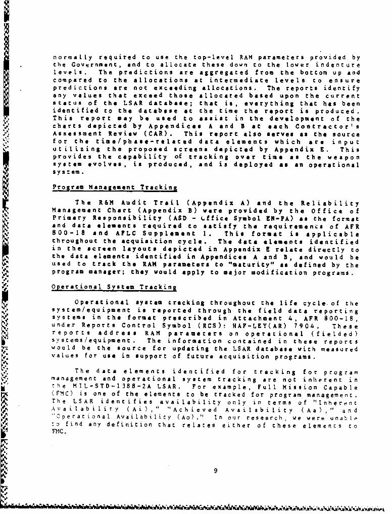
normally required to use the top-level RAM parameters provided bythe Government, and to allocate these down to the lower indenturelevels. The predictions are aggregated f.rom the bottom up andcompared to the allocations at intermediate levels to ensurepredictions are not exceeding allocations. The reports identifyany values that exceed those allocated based upon the currentstatus of the LSAR database; that is, everything that has beenidentified to the database at the time the report is produced.This report may be used to assist in the development of thecharts depicted by Appendices A and B at each Contractor' sAssessment Review (CAR). This report also serves as the source
for the time/phase-related data elements which are inpututilizing the proposed screens depicted by Appendix E. Thisprovides the capability of tracking over time as the weaponsystem evolves, is produced, and is deployed as an operationalsystoem
Program Management Tracking
The R&M Audit Trail (Appendix A) and the ReliabilityManagement Chart (Appendix B) were provided by the Office ofPrimary Responsibility (ASO - 4.ffice Symbol EN-PA) as the formatand data elements required to satisfy the requirements of AFR800-18 and AFLC Supplement 1. This format is applicable
throughout the acquisition cycle. The data elements identifiedin the screen layouts depicted in Appendix relate directly tothe data elements identified in Appendices A and B, and would beused to track the RAM parameters to "maturity" as defined by the
program manager; they would apply to major modification programs.
Operational System Tracking
Operational system tracking throughout the life cycle of theNesystem/equipment is reported through the field date report~ing
systems in the format prescribed in Attachment 4, AFR 800-18,
under Reports Control Symbol (RCS): HAF-LEY(AR) 7904. Thesereport s address RAM parameters on operational (fielded)syscems/equipment. The information contained in these reportswould be the source for updating the LSAR database with measuredvalues for use in support of future acquisition programs.
The data elements ident i fied for tracking for programmanagement and operational system tracking are not inherent inthe MIL-STD-1388-2A LSAR. For example, Full Mission Capable(FMC) is one of the elements to be tracked for program management.The LSAR ident i fies availability only in terms of "Inhere. ntAvailabi lity (Ai ) , " "Achieved Ava i 1 abi li (Aa) ," and"Operacional Availability (Ao) ." In our research, we were unable:o find any definition that relates either of these elements coFMC.
9

The REMIS RFP is not clear as to the Air Force policyrelative to the retent ion of the LSAR data after fielding. Ifthe UDB 2000 database is expanded to incorporate the additionaldata elements, this will still leave a void in the data systemfor acquisitions that do not use UDB 2000. Assuming that therequired interface with REMIS is incorporated, there is theproblem of where the data will be stored for those systems notusing UDB 2000. This would appear to be essential to consistencyin trackinag capability.
10
I• [ • •1[,I• •1,• 4q,.• • •I- &•, , ••, •,a,• ••,,•.• M•,•'• •1 ••P_-- #.A A, m A• ' • x" fw' •,• " %'•,A' A•,W "PLO ,%-,X" %,a, "• Xv%"€• "AA

APPENDIX A: R&M PROGRAM AUDIT TRAIL
11

%A
t0
~EEO
OWL
4K z0cLcLI
31-
AS .24i
eu.-v
w
A.A L".
212

TITLE: RELIABILITY AND MAINTAINABILITY PROGRAM AUDIT TRAIL
REQUIREMENT: Mandatory chart for CAR/PAR/SPR briefings.
PURPOSE: To portray and monitor critical R&M parameters and the rela-tionship between user needs, program direction, contract requirements,demonstrated/tested/projected values, and field performance.
INSTRUCTIONS:
1. The format will be an audit trail between the user needs,program direction, projected value, demonstrated/tested value, and fieldperformance. The audit trail will be shown for the new system and for apredecessor defined as an operational system which is most similar tothe new system and will be used for historical comparison. If nosuitable predecessor system exists so state.
a. User need. Normally stated in the SON. (New and predeces-sor.)
b. Program management direction. The value that is containedin the program direction document (normally the PMD). If different fromthe user requirement explain why. (New system only.)
c. Contractual requirement. The specification or contractualvalue. If measured differently than the first two values indicate and beprepared to explain. (New system only.)
d. Projected value. The PM's assessment of the value that willbe attained at maturity (define maturity). Explain basis of projection.Parameters will be consistent with the contractual requirement. (Newsystem only.)
e. Demonstrated/tested value. This value, with parameters tobe consistent with the contractual value, will be based on actual demon-stration/test data. The data may be from development test, a reliabilitygrowth development test, a MIL-STD 781 test, a maintainability demon-stration, or a combination thereof. The PM must be prepared to explainthe source of the data (New system only.)
f. Field value. This will be the value, measured in opera-
tional terms, based on IOT&E/OT&E and/or actual field use. (New andpredecessor.)
g. Program Manager's Assessment. This block will be colorcoded using the following guidelines which are intended to aid the
-% program manager in making an assessment of the audit trail parameters.
% (1) Each audit trail parameter will have its own programmanager's assessment and will be rated as follow.:
13
% ~~~~ ~N I . %* .~~ . .

(a) Satisfactory (green). Satisfactory indicates thatthe c-ntractual requirement, projected value, and any measured value(demonstrated, tested, and/or field value) meet the user/PMD require-ment.
(b) Marginal (yellow). Marginal indicates an existingproblem for which there is some question whether the contractualrequirement, projected value, or any measured value meet the user/PMDrequirement. However, the problem appears to be within the programoffice's or product division's ability to solve and an action plan isunderway to solve the problem.
(c) Unsatisfactory (red). Unsatisfactory indicates aserious problem exists in which the contractual requirement, projectedvalue or any measured value will not meet the user/PMD requirement andrequires the assistance of HQ AFSC and/or HO USAF for resolution.
(2) The program manager should be prepared to addressrationale for the assessment of each parameter.
2. As a minimum, a matrix vill be shown for each critical R&Mparameter stated in a program direction. If a particular value for agiven box is not available enter NA; if the box is not applicable enterN/A. (Note that the R&M parameters and values shown are for illustrativepurposes only. The PM must select the parameters from attachment 1 ofAFR 800-18 that are critical for his/her program.)
3. In the example asterisks are entered in three boxes of the FMCmatrix indicating further explanation is needed. In this case FMC is notmeasured directly but is derived from MTBM and MMH/FH. The PM must beprepared to discuss such "exceptions."
14

SAPPENDIX B: RELIABILITY MANAGEMENT CHART
A'
-'A
A,

SI C
!i -\ I -i • t I I IICS:<,i .\o• ! I~t
I I C~•.
I-a
XI -'
_• .,-.,,,-,.- ,.... . . . . . . . ,Wil,'•.,,...,•-,,-, ,..-,-I, U.• 'v-•,•',•'-

TITLE: RELIABILITY MANAGEMENT CHART
REQUIREMENT: Mandatory chart for CAR/PAR/SPR briefings.
PURPOSE: To illustrate how the reliability program is being managed tociRTeve the mature requirement, to show the relaticnship between key
factors and/or phases of the reliability program, and to track progressin meeting the mature requirement.
INSTRUCTIONS: The critical reliability parameter (e.g., MTBF) will beplotted on the vertical axis using the proper life units (e.g., cycles,rounds, hours). Along the horizontal axis the acquisition phase andcalendar time will be shown. Below the calendar time the cumulative testlife units will be shown.
1. A dotted horizontal line will be used to indicate the contrac-tual tequirement with the actual value in parentheses.
2. A dotted vertical line will be used to indicate the "today"point on the chart.
3. The chart should depict where the PM "plans to be" at anypoint in time for the reliability parameter. The resulting "curve"should oot necessarily be construed to be a reliability growth curve inthe stric, sense of the term and as described in MIL-HDBK-189, althoughthe PM has Zhp 141cretioe. to use such a curve if it is appropriate forthe program.
4. Indicate with solid bullets the predicted value (or projectedvalue if MIL-STD-756 is not used. In this case be prepared to discussthe basis for the projection).
5. Indicate with an "x" values of the parameter based on testresults. Below the calendar time indicate the type of test (TAAF, RQT,flight test, etc.) and test hours.
"6. Indicate threshold (DSARC, AFSARC, etc.) values with circles.
7. Show key milestones, such as CDR and IOC. For clarity omitmilestones that predate the briefing date.
8. Show the projected "Growth" (if different from planned) andexplain variances. In the example the planned "growth" accounted forexpected learning during the transition from design to production andshowed the contractual requirement being achieved at IOC. The projectedcurve shows a jump because a new technology, not mature when the programwas initiated, was approved at CDR and will be implemented prior toproduction decision. The PH must be prepared to discuss such "anomalies"as well as other implicit details (e.g., number of test articles, numberof unincorporated design fixes, definition of failure, etc.).
9. The contractual value, in this example, was decreased slightlybased on the results of dem/val. The Reliability and MaintainabilityProgram Chart will show how the current contractual value is related tothe operational need.
17

AP t PENDIX C: RELIABILITY GROWTH AT THE COMPONENT LEVEL
.2
.4
,ml
h18
U 4J

RELIABILITY GROWTH
Concept - The successful design, development, testing andproduction of a new weapon sys tem (such as the F-16) dependsgreatly upon two resources: time and money. Typically, acontractor is asked to produce a complex weapon system orcomponent thereof in minimum time at minimum expense in acampet itive e!nvironment. More often than not, the result is aproduct whi:h has not been sufficiently tested to identify designand manufa(turing imperfections. These imperfections manifestthemselves as failures - the inability to perform in accordancewith specification requirements.
Early in th1 operational life of the weapon system, the userevaluates the effectiveness of the system through actual use. Asfailures occur, the user places significant "emphasis upon theneed for corrective action which will render the item or system
4" acceptable. As a result, the contractor usually becomes4 motivated to analyze the failures, determine the basic cause of
the failures and then effect corrective action in the item, intech data and/or in SE. The result is an item wi th improvedreliability characteristics or "reliability growth."
Duane Postulate - Quantification of reliability growth was notcommonly done until after 3. T. Duane recognized a patternedrelationship between failure rates and cumulative operating time.
The following excerpt from a paper by J. D. Shelby and S.G.Miller, "Reliability Planning and Management (RPM)," brieflyexplains the "Duane Postulate."
Origin of Reliability Growth
The basic concept of a patterned reliabilitygrowth.., was first recognized and published by J. T.Duane of GE Company's Motor and Generator Department in
1962. His analysis of test and operational data forprograms with test times as high as 6 million hours onfive divergent groups of products (two hydro-mechanicaldevices, two complex aircraft generators, and a jetengine) formulated a pattern which resulted in thefollowing concept.
. a. Rel iab I i t i improvement of complexeq u i pme n t fol lows a m a t h e m a t i c a ypredictable pattern.
19p..
• m, pw-% •- .- • - e .e • ., -" -" -," * " . .

b. Reliability improvement is approximatelyinversely proportional to the square root ofcumulative operating (test) time.
I
R (O
c. For a constant level of corrective act{ion
effort and implementation, reliability growthclosely approximates a straight line on a logs ca Ie.
Th is pattern has been confirmed to be applicable toavionics equipment by GE/AES from data on four separate
programs. (End of quote)
Init ial Provisioning - 00-ALC/MMAR, through the Resident
Integrated Logistics Support Activity (RILSA), applied the above
concept to the F-16 initial provisioning process as describedbelow:
- Mature (@ approximately 100,000 flight hours) MTIF
values for LRUs were developed via a comparabilityanalysis using a similar equipments on other matureweapons systems.
- The mature MTBF values were factored to generatemature MTBD values. These mature MTBD values are theMTBCT values entered on each F-16 Optimum Repair LevelAnalysis (ORLA).
- Corrective Task Z Mature MTBD
-' - Using the reliabiliLy growth concept in reverse, eachmature MTBD was "derated" or factored Co reflect a lessreliable situation early in the operational life of the
F-16 (the derate factors varied depending upon thenature of the item). The "derated" values were enteredin the ORLA as the "FINIAL GOVERNMENT APPROVED" valueand, in most cases, on the initial RILSA Data Worksheecused for initial provisioning. The derate factor was
*. based on projected growth curves for ,TBF at LRU andsubsystem levels. An assumption was made that thegrowth rate for MTBF (same as MTBM (inherent) today)was the same for MTBD.
"" Follow-on Provisioning - If the reliability growthassump:ion (as applied above) is correct, then itemsshould show improvement as operational flight hours areaccumulated. To quantify this expected improvement,
, ~MMAR developed a series of mini-programs based on the
20

Duane Postulate wh ich provide t he t echni ci4answith maintenance factors for t he f irs t, second andthird forecast periods. These procedures (attachment1) are not used for all items or in all situations, butare used where deemed applicable by the technician andsection supervisor.
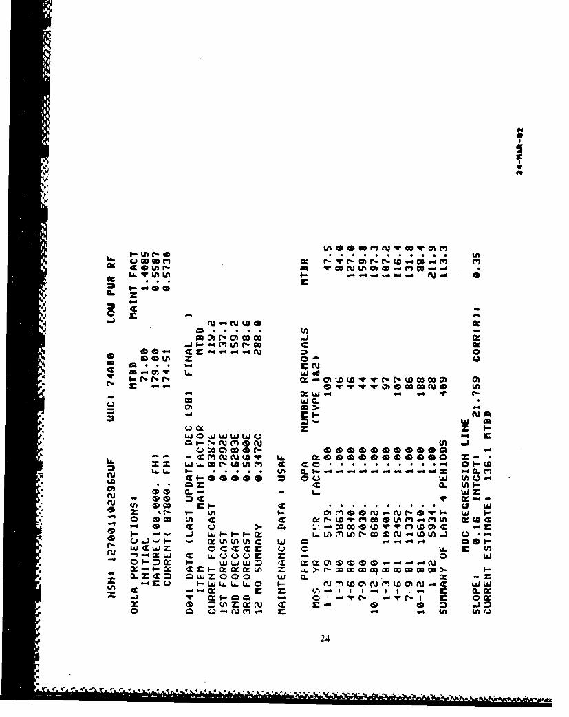
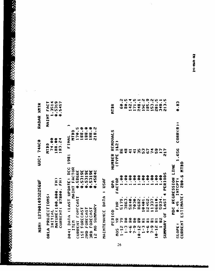
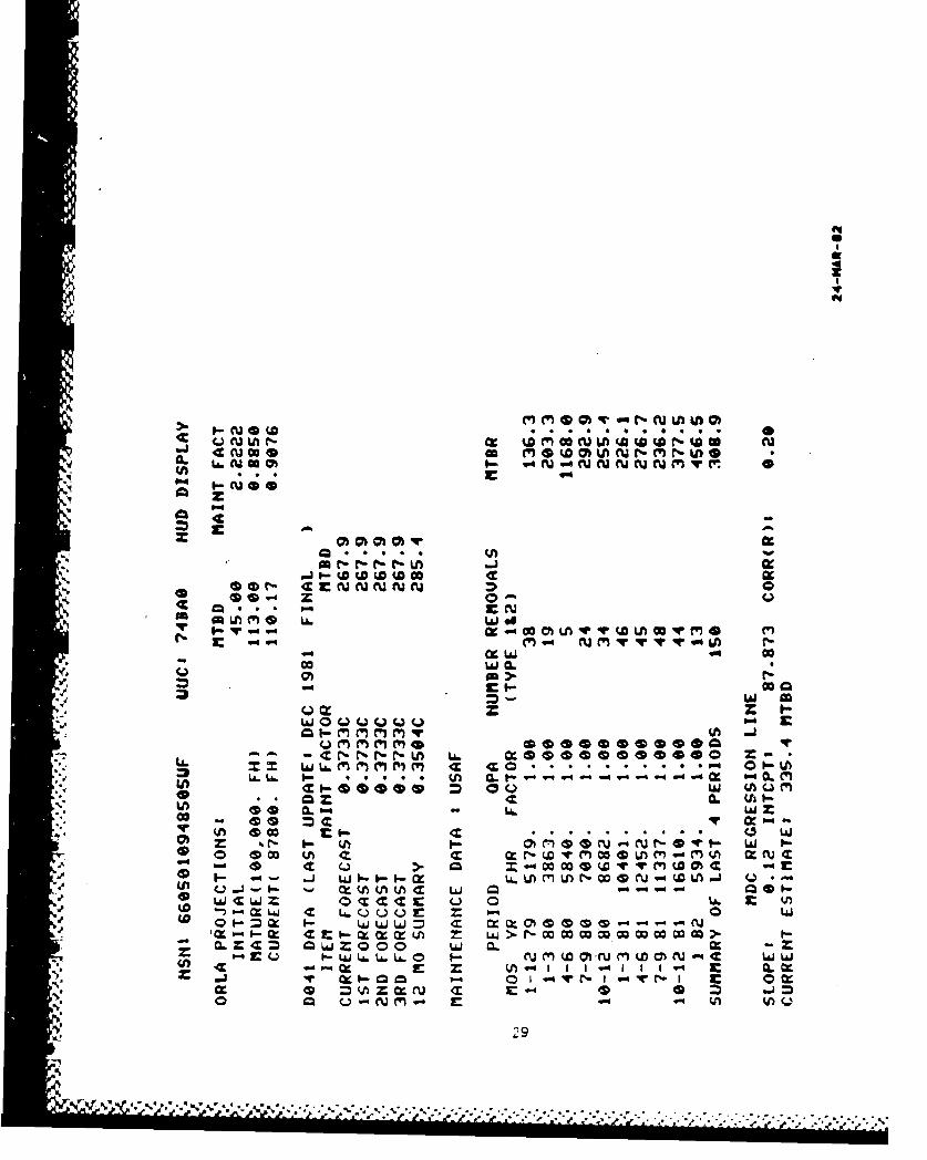
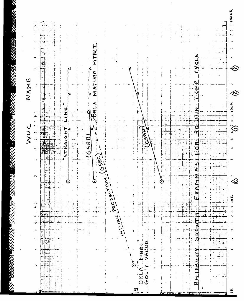
Examples - Attachment 4A contains examples of the twomost common reliability growth curves. Included arethe ORLA, the RP97 printout, a graph of the RP97 data,and a computer generated chart shoving relationshipsbetween ORLA, D041 projected values, and maintenancedata removal rates. Note that the D041 values shown onthis chart are based on the initial D041 products andwill be changed to reflect the new forecast values whenthe final D041 products are available.
Source: AFALC/ERR
'21

z
ww
cz I.- to LhffJ
0- -fW4ý4V
0 Ma
co * * *L
QCLf L&. LAL L
zI L6LA. 1ý goI " L(
. # L ulI-
o .5 c c 1- Lai
%a.i r- V) *M O -C t" *D *wý Wj ý
_5 -L U) M Ulw 4(AL -
w 0 Q 0 1.-
o _=c I- La W jJi-l C x x0UL3 w < U). .
Q Qý-- 'UJ')J t LU6 0 0*3-
cuuLAJL&JW22

0 . ... .. . ............. ..................
......... 4.. .. . ...... ! ....... . ......
*l . S
~................. ............................... ................ ............. . at
(44 .0
Z
....... ......... ............... .............. .........-.... ..N
... LI cgs
ý . . Zp.
d4
49
(4
c 0U) - 0 ~w M N 0 as Mwi
CU~U CU(A40(
.3 -4 (V N ca
.. ". . .
Ir U.U. w
U wok w
an >.
4 0. W LI Ww-*Q I .'-. -l cu m f
Q CIO** ** OIC W
d3 L6 L6 I.- . I- 0 . . V) CL uZ iCL -cu 0t00 6 *W qi 'A Q MO . U
cu U 0'-I 0 =WV~ I- Cc *%- W4L&J 0V)~ C7 MO U. C
<9 o 0M M0 0M M0 cz A
Q 0Ij C LjJLJLJ W-4 0--4
w c ~ 0 w E Q ((fl i LAJ U.L.L. W - (X (s00G -- - - 4 LJ
m w - woi-wwwoqwwwwwW IA. C L6 L6 0 w wJ
24

-..... .. ...... .-....... ....... .
....... ....... ............... . .....
0 ......................................... ..
-4 L6 W -a
a 'w
z * w w4
o........................T................. ....-......... bob-Iz -Z Qi
(~~) a
G*0 CD CD0OD
U) N bLP
a wh
U * * 1 25
U LA r; c
4z LnM v 0 Vm LA Lin
.J'~~U I- N Cc CcM we
t- -lc I
Ln~eeru
o a..goENc I. La.
qCmm w
cu LhQD
Q~~~ mCOUa WW -5 - Y a
::WCL=flhV C = a w = o o w G.-*00 Q (nUN .U.L.
-d 0- ( c( (L I-cz -- (ZI
'J~ *OZCI
~- I- (n I *~NJ~-Q~- 26
------- ------- ------

(.CD
...... ...........
J-
S.............' ............... ............. ............ .................. L" ........... •
...... ... ..... ... .. ... ... .............. ... ... .. .. . . ...... ...... 49
-- ° ° ° o -*.o a e e o o . *
. 20
Si............ ..... ....................... ..... ..... . ............ .
-,, -- -
*. 01 49
, z
... . . I 4 I . . ................. ............ .L-~~~i bi__ _ __ _ _ _iWg
0c of ~ZC. * Jo Z IX0
r .A ........L.........L... ......... .. ............. N j W b
G .
U) ~,

~~~~~.. . . . . . . ........ . . . .......... ! ......... -. . . . . . . . . ,. . .. .. , ,• -
S ........... .......... . .._ ..-....'... ... . '-..........-
............. ......................... 1 ......... .. ...-
.0
4" 4c
........... . . .... . ............... . IM A
*Q i
' _-
.--
.. . . . .
z z f.
40 *u 0.at 7
is* x 0
Z CZ
28 ~
IA c
w it~ ~ ClJG IN'NNNNC1yN 0
Oo
0 . .P" . sr,)im U) n o L
*,r- I.- ccC~ 0
U ~ -CNNNN La6 LJLL w'- U.MMMMM -V
:3 U.LwI- * *o .J-ý : C
ul w mL00(.Q~ L Ch
00 C. L.60qr0 CI-O- i.
Is 0~ cl- N c ~4) ZA 1.- 10- Jr LA. Lo M n - cc 4p C -0- (aJ LA-Q
0La.J4~iJ6 Q~4 u.. 0 0f
0l Z~ c- m JL.JA 4- cy=mi > M W W
1W 6La.LU. &0 M- W LaMJD M
ex 0.l~' C"NI-v -10r Qn ( X.'("~ ri C4 ID
.9. 19

.* - -. . L
* ,. Q- 4JA
.. .. .L.0
qvq
........... ....... !. .. .......-
Ub. 0 4
b. 04
a &LAJL& on x
....... ....................... ..................... 4 C
aa *
(.. (S G G EE
- .l .)
00Z J(- J4 Z
30 ~ ., -

CL4
P-44
0.rKQ
ol >
c enw on
I- m KQ c oo. r-r-
L6 U. t- KCL . L(A 0- (A'Lfsu Q0
CU wo=
-3OLLWW -X w )MU NC
n xw C Q Q - Lii .)'
0- ýC- I.- c f m. = m '-wm% M WCCL- X. Z M Q w Z (Vt AJ C
0* tA. LA. L&?-- *j a. . LaPi AJ qr I-- P" 0 1. 0
cc M (Z N C Z c
* .~ O~ i Z O O OU. a. 31

.. ....... f.. .t..
S.4.... ..................... ... ~....
1- *
z z
.0 z
110
4. . G
0 G C* .)
32w

I--c
z
CO@O m
09 I- - 0 %
Q * * . *4 c) f
in wr- ILA. w 0.
. 9 . c r .
w~ Q.
w~i ZIP--i'
9?~~~ cr.~~Q
w 0 w (AJ Q IT9, CU (h~
9 CL LA.J - UU U U > w z
0 m cc~r0 w .-% (,-- 0LJ~L~L. IM~( 0 C ~ ~ L
a 4m (to~ (A a xWMmM COC
p- w'-(k L6 Un mcc w C C-0r
CL C 0 0 0 w 0
33
% N*.% S % %' v9.9' *'% % IV"*

APPENDIX D: RELIABILITY GROWTH PROCEDURES
4..
34
-- - - - - - - -

D041 GROWTU/PROJECTION CURVE PROCEDURES
1. ASSUMPTIONS :
"a. Reliability growth is described through a mathematicalfunction vhich can be plotted as a straight line onlog-log graph paper (Duane Postulate).
b. In general, mature reliability is achieved atapproximately 100,000 FE. (Individual items willobviously mature at different points of time.)
c. The init al baseline growth rate (reference paragraph 2bbelow) is the maximum race expected.
d. The contractor MTBCT (mature NTBD) is the maximum valueexpected.
e. Production equipment growth curves begin at the 2000 FH(end of FSD) point on t he curve. This point isequivalent to "0" production aircraft FH.
"2. PROCEDURES:
a. On a quarterly basis, the reliability engineerdetermines the projected FH values for the beginning of"the I st , 2nd, and 3rd forecast periods using PA/D041values. Two thousand (2000) Fh are added to each value"to compensate for starting the growth curves at 2000 FH.
b. The baseline growth curve is constructed using "FINALGOVERNMENT APPROVED" ORLA maintenance factor (at 2000
* ,FR) and the contractor MTBCT value (at 100,000 FR).
c. The current projected value ("P') for MTBD is ex.ractedi- from the baseline curve at the end-of-quarter cumulative
FH * 2000 FE point.
d. Using all data, knowledge, experience, etc., available,the technician esti.mates the current MTBD ("E") of thei Ltem.
e. The applicable growth techniques are applied using thefollowing criteria:"(1) If "E" is greater than MTBCT, use "E" as the
value for current, 1st., 2nd, and 3rdI forecasts.
3S
A.& OL *A*

(2) 1f "E" is greater than "P" , but less thanMTBCT, cons truct a now projected Line from the"E" value (at current FL plus 2000) to MTBCT.
(3) If "E" is less tha n a"P", construct a lineparallel to the baseline grovth curve,beginning at the "E" value and current PH plus2000 FR. Continue the line to the MTBCT valueor the value corresponding to the 3rd forecastFH, vhichever occurs first.
f. The corresponding Ist, 2nd and 3rd forecast MTBD valuesare extracted from the curve generated in paragraph 2eabove. These MTBD values are then converted tomaintenance factors.
S. The computations referenced in 2b, 2c, 2e and 2f areati.tomated via a program which is run on the HP97calculator.
PIN
36
Il
q00
ii!t ,-
* - H- 1 ;> A I -
I-.
I I -*' .�ji*j �. A . V
U.) �:i' rIII 1� - I, I
Id I . .1 Qt
z �j. 'I . I
2
4 1�0 I � �-
�J. III� H1 *1
I I. I --- *1
I: -
I.' . . j: -i
I II!i� ...................................................................................................................................................--
,.ri . i . -.
1< I-* I � 0
�1 7 j.j.-i r .. * ' 'P �. I. f I
-J I f'-A - 4.
-A �. I -
* . I
* �.\II' I I*j I
' IT I�*I >�uI�1 >1------HF! I '-IB Li:.; . 1 ___
0 h II-.. . I
A, I, 37 I

APPENDIX E: R&M TRACKING SCREENS AND REPORT FORMATS
8
4.
4.
U
W3

R&MI UDB 2000 LSAR DATA SCREEN DATE / /R&M TRACKI NG DATA TIME _ _
USER-------------------------------------------------------------------- 4
END ITE"Mi ACRONYM CODE:
NTBF (BRS) (ORG LVI) FCPREDECESSOR:USER REQUIRMENT! - .
- NEW SYSTEM:- USER REQUIRMIENT: . - .
PDM VALUE:-- CONr REQUIRM4ENT: - .
THRESHOLD VALUE:
I DATE/USER LAST UPDATE:
"439I.-
4|,
SI. " " . " " - ., " " " " " . - " "" ," " -' ." "," "," ', ".t ", v' ," . . a.• , , . , '• ,'

R&M2 UDB 2000 LSAR DATA SCREEN DATE /_/R&M TRACKING DATA TIME : :
USER---------------------------------------------------------------------------------------------------------------
END ITEM ACRONYM CODE:
DATE DATEACQUISITION PHASE: BEGINNING ENDING
CONCEPT: // /fDEMONSTRATION/ VALIDATION: - / /-/FULL SCALE DEVELOPMENT: - / /-PRODUCTION: -/ /
DATECRITICAL DESIGN REVIEW: / /FIRST "LIGHT: --PRODUCTION DECISION __/-/
I IOC:STAF.T TESTING: __/__/_
DATE/USER LAST UPDATE:
40
*, - . . . . . . .

R6?13 UDB 2000 LSAR DATA SCREEN DATE /__R&M TRACKING DATA TIME :_:
USER
--- ---------------------------------------------------------------
END ITEM ACRONYM CODE:
NEW SYSTEM:PROJECTED/PREDICTED VALUES:
cum leAR/FHTYPE OF TEST DATE FLT RRS MTBF(HRS) (ORG LVL) Fmc
I_ _ / .-. .
/ /...III- .
I _I_._./.
_ _ _ _I--I--
_ _ _I I ._ I
DATE/USER LAST UPDATE:
41

R&M4 UDB 2000 LSAR DATA SCREEN DATE / /R&M TRACKING DATA TIME
USER
END ITEM ACRONYM CODE:
NEW SYSTEM:DEMO/TESTED VALUES:
cum MKH/FHTYPE OF TEST DATE FLT JIRS MTBF(HRS) (ORG LVL) FMC
/__ _/I . .
DATE/USER -AS -PDATE:
-- _/ -/ --- . .--__ _ / -/ --- -._ _- __ . -_-.
_ _ _/ / . .
3 I --/ -- / ... .
IDATE/USER LAST UPDATE: _________
.1
IeV4

R&M5 UDB 2000 LSAR DATA SCREEN DATE / /R&M TRACKING DATA TIME :
USER
---------------------------------------------------------------------- 4END ITEM ACRONYM CODE: •IMH/FH
PREDECESSOR: MTHBF(HRS) (ORG LV!.) FHC
FIELD/ACTUAL VALUE: I
INEW SYSTEM!FIELD/ACTUAL VALUE:
TYPE OF TEST DATE FLT fRS MTBF(HRS) (ORG LV!L) FMC
__ __/ I___/--/--___-- . -
_ _ _iI I
DATE/USER LAST UPDATE:
If.
N,
-' 43
. . . . .

- R&06 UDB 2000 LSAR DATA SCREEN DATE / /R&M TRACKING DATA TIME
USER--------------------------------------------------------------------------- ~
END ITEM ACRONYM CODE:
MTBF GROWTH:
CUM PLANNED PROJECTED
TYPE OF TEST DATE FLT HRS GROWTH GROWTH_ _ _/ / -
_ _I I --- .: -- '-
DATE/USER LAST UPDATE:
iw,
.o
',1
'I"
S..
.,•
'• 44

trcI~ .,.Jw: 1&~''r..w' a .. 'a~a> a m a RR an. AJa a..P Um~ h Ndww~wwW' Ir wlwv5u
lmdI I
I~i .1 *I R.
i *, I 2
21i
I I I 4S

II
• *I G! 1111.
S° Io. I I :.j ,II I
4 46
",,••,, '' .".'"-•-. -" '."-T,'.- .. w,,- ,;,:•,,•,,.••", • • • , ,-•, I, I I,.,',• , .,,;,;

REFERENCES
Air Force Rogulations:
AFR 800-5 Acquisition Management, Selected AcquisitionReports (SARs), dated 18 March 1976.
AFR 800-18 Acquisition Management, Air Force Reliabilityand Maintainability Program, dated 15 June 1982.
AFLC Su.plement 1 to AFR 800-18, dated 10 May 1983.
Mliiitary Standards:
MIL-STD-470A Maintainability Program For Systems & Equipment,dated 3 January 1983.
MIL-STD-721B De finit ions of E f fect iveness Terms ForReliability. Maintainability, Human Factors , andSafety,, dated 25 August 1966, Revised 10 March"1970.
"MIL-STD-756B ReliabilitZ Modeling and Prediction, dated 18November 1981.
MIL-STD-785B Reliability Program For Systems ane EquipmentDevelopment and Production, dated l!5 SeptemberS980.
MIL-STD.-1388-IA Weapon System and Equipment Support Analysis,dated November 1981.
MIL-STD-1388-2A DoD Requirements For a Logistic Support Analysis., Record, dated July 1984 and Notice 1 , dated 14
February 1986..N,
MIL-STD-1629A Procedures For Performing a Failure Mode,Effects and Criticality Analysis, dared 24November 1980.
MIL-HDSK-217D Reliability Prediction of Electronic Equipment,dated 15 January 1982.
"NOTE: All of the reference documents are currently on file at•.SS .
47

GLOSSARY
AFALC - Air Force Acquisition Logistics CenterAFLC - Air Force Logistics CommandAFSARC - Air Force Systems Acquisition Review CouncilALC - Aerospace Logistics CenterCAR - Contractor Assessment ReviewCDR - Critical Design ReviewCY - Calendar YearDoD - Department of DefenseDSARC - Defense Systems Acquisition aeviev CouncilFIMC - Full Mission CapableFSD - Full-Scale DevelopmentHQAFSC - Headquarters, Air Force Systems CommandHQUSAF - Headquarters, United States Air Force1OC - Initial Operational CapabilityIOT&E - Initial Operational Test and EvaluationLRU - Line Replaceable UnitLSA - Logistic Support Analysis.LSAR - Logistic Support Analysis RecordMDC - Maintenance Data CollectionMMH/FH - Maintenance Manhours per Flight HourMTBF - Mean Time Between FailureMTBD - Mean Time Between DemandMTBM - Mean Time Between MaintenanceMTBR - Mean Time Between RemovalOPR - Office of Primary ResponsibilityORLA - Optimum Repair Level AnalysisOT&E - Operational Test and EvaluationPAR - Program Assessment Review
SPM - Program ManagerPMD - Program Management DirectiveRAM - Reliability (R), Availability (A), and
Maintainability (M)RCS - Reports Control SymbolREMIS - Reliability and Maintainability Information SystemRQT - Reliability Qualification TestR&M - Reliability (R) and Maintainability (M)SON - Statement of NeedSPR - Special Program ReviewSRU - Shop Replaceable UnitUDB - Unified Data Base
S48
.'
4,.
4'" . -... . - • • ... . . . . . .. .. 4 4- 4'44 . .4 -4

Df/c-
S.0
7r/C-.
JA