air handling units unità trattamento aria - rdz · air handling units unità trattamento aria ......
TRANSCRIPT
Air Handling UnitsUnità Trattamento Aria
SILAVENT HRX
TECHNICAL/INSTALLATION MANUALMANUALE TECNICO/INSTALLAZIONE
Mechanical ventilation with heat recovery applianceVentilazione meccanica con sistema di recupero di calore
9100
328.
02 -
03/2
016

3
Le g g e re co n at te n z i o n e q u e s to l i b re t to p r i m a dell’installazione e/o dell’uso dell’apparecchiatura e conservarlo in un luogo accessibile.La presente apparecchiatura costituisce un componente che fa parte di installazioni complesse: è compito dell’impiantista elettrico redigere lo schema generale dell’impianto e dei collegamenti elettrici esterni all’apparecchiatura.L’ufficio tecnico del Costruttore si rende disponibile ai numeri indicati sul retro del presente libretto per consulenze o richieste tecniche particolari.
• ATTENZIONEL’installazione e la manutenzione vanno eseguiti solo da personale qualificato. Gli impianti idraulici, elettrici ed i locali di installazione delle apparecchiature devono rispondere alle norme di sicurezza, antinfortunistiche e antincendio in vigore nel Paese di utilizzo.
• E’ indispensabile collegare l’apparecchiatura ad un efficace impianto di terra e includerla in un sistema equipotenziale la cui efficacia deve ottemperare alle norme in vigore.
• Prima di eseguire il collegamento elettrico, accertarsi che la tensione e la frequenza riportate sulla targhetta caratteristiche corrispondano a quelle dell’impianto d’alimentazione.
• Prima di effettuare qualsiasi intervento sull’unità, assicurarsi di aver tolto l’alimentazione elettrica.
• Non alterare o manomettere i dispositivi di sicurezza.• Non dirigere spruzzi d’acqua sulle parti elettriche o
sull’involucro dell’apparecchio.• Questo apparecchio è inadatto all’utilizzo in atmosfere
esplosive o potenzialmente esplosive.• All’atto dell’installazione o quando si debba intervenire
sull’apparecchiatura, è necessario attenersi scrupolosamente alle norme riportate su questo manuale, osservare le indicazioni a bordo unità e comunque applicare tutte le precauzioni del caso.
• I componenti elettrici presenti possono creare situazioni rischiose durante gli interventi di installazione e manutenzione.
• Questa apparecchiatura non è appropriata per l’utilizzo da parte di bambini o persone inferme senza un adeguata supervisione
Read this manual carefully before installing and/or using the equipment and keep it in an accessible place.
This equipment constitutes a component which is part of complex installations: it is the responsibility of the electrical installer to draw up the general diagram of the system and the electrical connections outside the equipment.The manufacturer’s technical office can be contacted on the numbers shown on the back of this manual for queries or special technical requests.
• CAUTIONInstallation and maintenance must only be carried out by qualified personnel.The hydraulic and electrical systems and the places where the equipment is to be installed must comply with the safety, accident prevention and fire prevention standards in force in the country of use.
• It is essential to connect the equipment to an effective earthing system and include it in an equipotential system whose effectiveness.
• Before making the electrical connection, ensure that the voltage and frequency shown on the data plate correspond to those of the power supply system.
• Before performing any intervention on the unit, ensure that the electrical power supply has been disconnected.
• Do not alter or tamper with the safety devices.• Do not direct jets of water onto the electrical parts or onto the
equipment packaging.• This appliance is not suitable for use in explosive or potentially
explosive atmospheres.• During installation or when it is necessary to intervene on the
equipment, it is necessary to follow the rules shown in this manual very carefully, respect the information on board the unit and always take all the appropriate precautions.
• The electrical components may create dangerous situations during installation and maintenance interventions.
• This appliance is not intended for use by young children or infirm persons without adequate supervision.
SAFETY WARNINGS - AVVERTENZE PER LA SICUREZZA
GENERAL WARNINGS - AVVERTENZE GENERALI
• Se dopo aver disimballato l’apparecchiatura si nota una qualsiasi anomalia non utilizzare l’apparecchiatura e rivolgersi ad un Centro di Assistenza autorizzato dal Costruttore.
• U n o s c a r i c o c o n d e n s a d e v e e s s e r e i n s t a l l a t o dall’apparecchiatura ad uno scarico appropriato.
• Lo scarico condensa e tubazioni associate devono essere liberate dai detriti prima della messa in funzione e isolati se passano attraverso spazi non riscaldati o vuoti.
• Questo apparecchio non deve essere collegato ad un’asciugabiancheria o cappa d’aspirazione.
• L’aria in ingresso di alimentazione deve essere prelevata dal l’esterno della proprietà.
• L’aria di ripresa deve essere espulsa verso l’esterno della proprietà.
• If, after having unpacked the equipment, any anomaly is noted, do not use the equipment and contact an Assistance Centre authorised by the manufacturer.
• A condensate drain should be installed from the appliance to an appropriate drain location.
• The condensate drain and associated pipe work must be cleared of debris prior to commissioning and insulated where it passes through unheated spaces and voids.
• This appliance should not be connected to a tumble drier or cooker hood.
• The supply air must be drawn from the exterior of the property.• The extract air must be expelled to the exterior of the property.
4
In base a quanto previsto dalle seguenti direttive europee 2011/65/UE, 2012/19/UE e 2003/108/CE, relative alla riduzione dell’uso di sostanze pericolose nelle apparecchiature elettriche ed elettroniche, nonché allo smaltimento dei rifiuti.
Il simbolo del cassonetto barrato riportato sull’apparecchiatura indica che il prodotto alla fine della propria vita utile deve essere raccolto separatamente dagli altri rifiuti.Al termine del ciclo di vita dell’unità, in previsione di una sua rimozione, andranno seguiti una serie di accorgimenti:Il gas refrigerante in essa contenuto va recuperato da parte di personale specializzato ed inviato ai centri di raccolta;L’olio di lubrificazione dei compressori va anch’esso recuperato ed inviato ai centri di raccolta;La struttura ed i vari componenti, se inutilizzabili, vanno demoliti e suddivisi a seconda del loro genere merceologico: ciò vale in particolare per il rame e l’alluminio presenti in discreta quantità nella macchina.
Tutto ciò per agevolare i centri di raccolta, smaltimento e riciclaggio e per ridurre al minimo l’impatto ambientale che tale operazione richiede.L’adeguata raccolta differenziata per l’avvio successivo dell’apparecchiatura dismessa al riciclaggio, al trattamento e allo smaltimento ambientale compatibile contribuisce ad evitare possibili effetti negativi sull’ambiente e sulla salute e favorisce il riciclo dei materiali di cui è composta l’apparecchiatura.Lo smaltimento abusivo del prodotto da parte dell’utente comporta l’applicazione delle sanzioni previste dalla vigente normativa in materia.
• Per l’installazione delle bocchette e griglie esterne si raccomanda di rispettare le indicazioni di posizionamento e le distanze minime di rispetto riportate successivamente in questo manuale
• Le tubazioni devono essere isolate quando passano attraverso spazi non riscaldati o vuoti (es. soffitte) per ridurre la possibilità di formazione di condensa e perdita di calore.
• Alla fine dell’installazione smaltire gli imballi secondo quanto previsto dalle normative in vigore nel Paese di utilizzo.
• Esigere solo ricambi originali: la mancata osservazione di questa norma fa decadere la garanzia.
• Il Costruttore declina ogni responsabilità e non ritiene valida la garanzia nei casi seguenti:- Non vengano rispettate le avvertenze e le norme di
sicurezza sopra indicate, comprese quelle vigenti nei paesi di installazione.
- Mancata osservanza delle indicazioni segnalate nel presente manuale.
- Danni a persone, animali o cose, derivanti da una errata installazione e/o uso improprio di prodotti e attrezzature.
- Inesattezze o errori di stampa e trascrizione contenuti nel presente manuale.
• Il Costruttore, inoltre, si riserva il diritto di cessare la produzione in qualsiasi momento e di apportare tutte le modifiche che riterrà utili o necessarie senza obbligo di preavviso.
In accordance with the provisions of the following European directives 2011/65/EU, 2012/19/EU and 2003/108/EC, regarding reducing the use of hazardous substances in electrical and electronic equipment, in addition to waste disposal.
The crossed-out rubbish bin symbol shown on the equipment indicates that, at the end of its useful life, the product must be collected separately from other waste.At the end of the life cycle of the unit, before its removal, the following precautions must be taken:The refrigerating gas contained within it must be recovered separately by specialised personnel and sent to collection centres;The lubrication oil for the compressors must also be recovered and sent to collection centres;The structure and the various components, if they can no longer be used, must be demolished and divided up according to the type of product: this is particularly important for the copper and aluminium components, which are included in the machine in moderate quantities.
All this helps collection, disposal and recycling centres reduce the environmental impact this operation requires.Appropriate separate waste collection for subsequent sending of the disused equipment for recycling, treatment and compatible environmental disposal contributes to preventing possible negative effects on the environment and favours recycling of the materials of which the equipment is composed.The abusive disposal of the product by the user leads to the application of the penalties envisaged by current regulations regarding the matter.
• External wall grill for the ducts shall be installed according to the instructions and minimum spacing reported in this manual.
• Ducting should be insulated where it passes through unheated spaces and voids (e.g. loft spaces) to reduce the possibility of condensation forming and heat loss.
• After installation, dispose of the packaging in accordance with the provisions of the regulations in force in the country of use.
• Use original spare parts only: disregarding this rule invalidates the warranty.
• The manufacturer declines all responsibility and considers the warranty invalid in the following cases:- The aforementioned warnings and safety regulations, including
those in force in the country of installation, are not respected.- The information given in this manual is disregarded.- There is damage or injury to people, animals or objects, resulting
from incorrect installation and/or improper use of the products and equipment..
- Inaccuracies or printing and transcription errors are contained in this manual.
• The manufacturer also reserves the right to cease production at any time and to make all the modifications which it considers useful or necessary without any obligation to give notice.
DISPOSAL - SMALTIMENTO
5
INDEX - INDICE
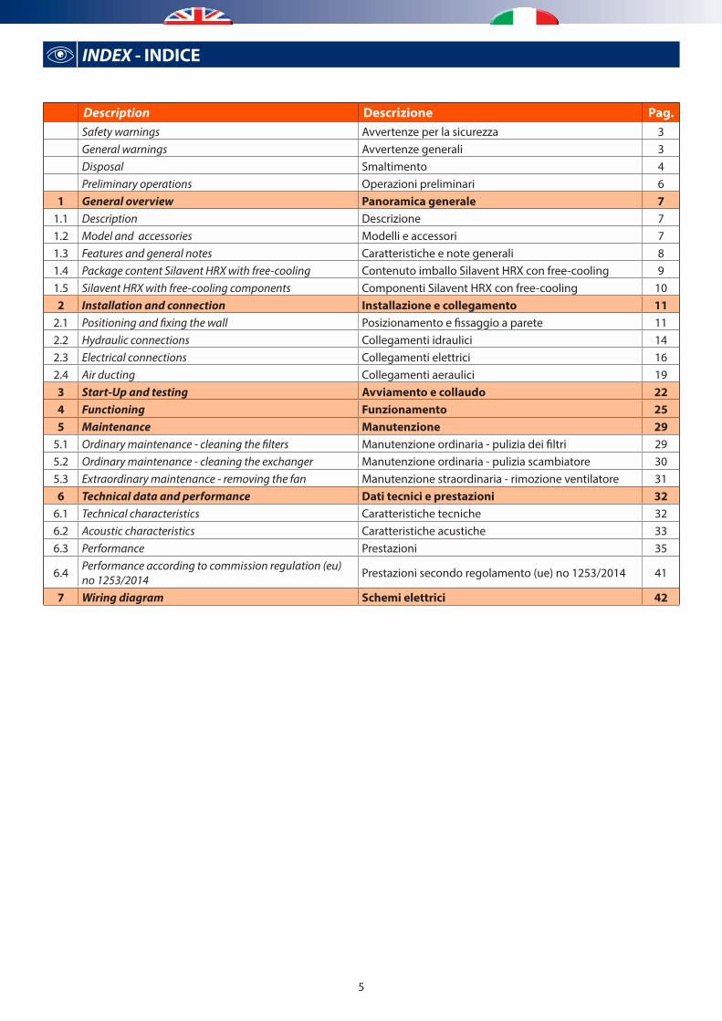
Description Descrizione Pag.Safety warnings Avvertenze per la sicurezza 3General warnings Avvertenze generali 3Disposal Smaltimento 4Preliminary operations Operazioni preliminari 6
1 General overview Panoramica generale 71.1 Description Descrizione 71.2 Model and accessories Modelli e accessori 71.3 Features and general notes Caratteristiche e note generali 81.4 Package content Silavent HRX with free-cooling Contenuto imballo Silavent HRX con free-cooling 91.5 Silavent HRX with free-cooling components Componenti Silavent HRX con free-cooling 102 Installation and connection Installazione e collegamento 11
2.1 Positioning and fixing the wall Posizionamento e fissaggio a parete 112.2 Hydraulic connections Collegamenti idraulici 142.3 Electrical connections Collegamenti elettrici 162.4 Air ducting Collegamenti aeraulici 193 Start-Up and testing Avviamento e collaudo 224 Functioning Funzionamento 255 Maintenance Manutenzione 29
5.1 Ordinary maintenance - cleaning the filters Manutenzione ordinaria - pulizia dei filtri 295.2 Ordinary maintenance - cleaning the exchanger Manutenzione ordinaria - pulizia scambiatore 305.3 Extraordinary maintenance - removing the fan Manutenzione straordinaria - rimozione ventilatore 316 Technical data and performance Dati tecnici e prestazioni 32
6.1 Technical characteristics Caratteristiche tecniche 326.2 Acoustic characteristics Caratteristiche acustiche 336.3 Performance Prestazioni 35
6.4 Performance according to commission regulation (eu) no 1253/2014 Prestazioni secondo regolamento (ue) no 1253/2014 41
7 Wiring diagram Schemi elettrici 42
6
1OK! RDZ
6
2a 2b
3b
3a
entro 8 giorniwithin 8 days
4
OK!
5
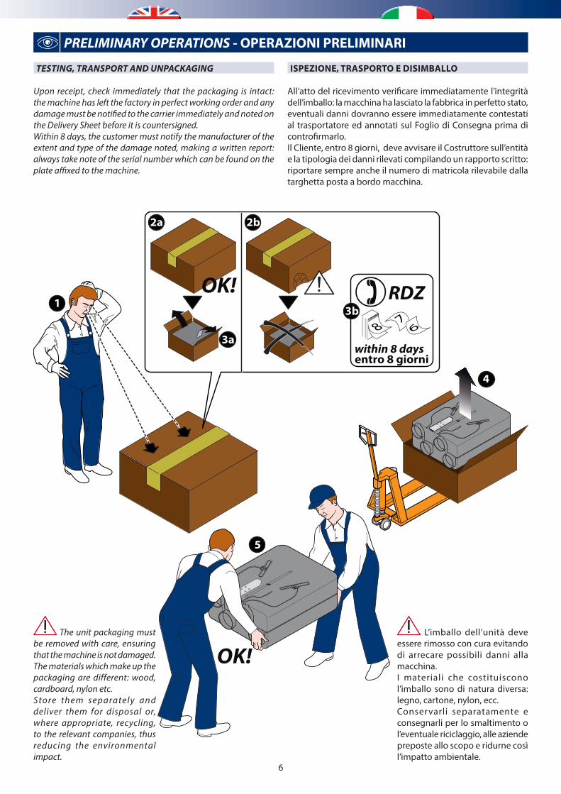
ISPEZIONE, TRASPORTO E DISIMBALLO
All’atto del ricevimento verificare immediatamente l’integrità dell’imballo: la macchina ha lasciato la fabbrica in perfetto stato, eventuali danni dovranno essere immediatamente contestati al trasportatore ed annotati sul Foglio di Consegna prima di controfirmarlo. Il Cliente, entro 8 giorni, deve avvisare il Costruttore sull’entità e la tipologia dei danni rilevati compilando un rapporto scritto: riportare sempre anche il numero di matricola rilevabile dalla targhetta posta a bordo macchina.
L’imballo dell’unità deve essere rimosso con cura evitando di arrecare possibili danni alla macchina.I materiali che costituiscono l’imballo sono di natura diversa: legno, cartone, nylon, ecc.Conservarli separatamente e consegnarli per lo smaltimento o l’eventuale riciclaggio, alle aziende preposte allo scopo e ridurne così l’impatto ambientale.
The unit packaging must be removed with care, ensuring that the machine is not damaged.The materials which make up the packaging are different: wood, cardboard, nylon etc.Store them separately and deliver them for disposal or, where appropriate, recycling, to the relevant companies, thus reducing the environmental impact.
TESTING, TRANSPORT AND UNPACKAGING
Upon receipt, check immediately that the packaging is intact: the machine has left the factory in perfect working order and any damage must be notified to the carrier immediately and noted on the Delivery Sheet before it is countersigned. Within 8 days, the customer must notify the manufacturer of the extent and type of the damage noted, making a written report: always take note of the serial number which can be found on the plate affixed to the machine.
PRELIMINARY OPERATIONS - OPERAZIONI PRELIMINARI
7
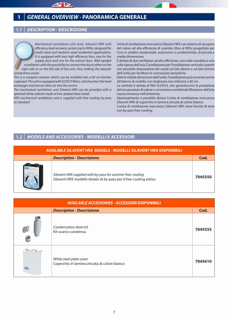
Unità di ventilazione meccanica Silavent HRX con sistema di recupero del calore ad alta efficienza di scambio (fino al 90%) progettata per l’uso in ambito residenziale, autonomo o condominiale, di piccola e media dimensione.È dotata di due ventilatori ad alta efficienza, uno sulla mandata e uno sulla ripresa dell’aria. È predisposta per l’installazione verticale a parete con possibile disposizione dei canali sul lato destro o sul lato sinistro dell’unità per facilitare le connessioni aerauliche.Date le ridotte dimensioni dell’unità, l’installazione può avvenire anche all’interno di mobilio con larghezza non inferiore a 60 cm.La centrale è dotata di filtri G3/EU3, che garantiscono la protezione del recuperatore di calore e consentono un’ottimale filtrazione dell’aria nuova immessa nell’ambiente.Opzionalmente è possibile dotare l’unita di ventilazione meccanica Silavent HRX di coperchio in lamiera zincata di colore bianco.L’unita di ventilazione meccanica Silavent HRX viene fornita di serie con by-pass free-cooling.
Mechanical ventilation unit mod. Silavent HRX with efficiency heat recovery system (up to 90%), designed for small-sized and medium-sized residential applications. It is equipped with two high efficiency fans, one for the supply duct and one for the extract duct. Wall upright
installation with the possibility to connect the ducts either on the right side or on the left side of the unit, thus making the aeraulic
connections easier.This is a compact solution which can be installed into a 60 cm kitchen cupboard. The unit is equipped with G3/EU3 filters, which protect the heat exchanger and ensure clean air into the rooms.The mechanical ventilation unit Silavent HRX can be provided with a optional white cabinet made of zinc-plated sheet metal.HRX mechanical ventilation unit is supplied with free-cooling by-pass as standard
1 GENERAL OVERVIEW - PANORAMICA GENERALE
AVAILABLE SILAVENT HRX MODELS - MODELLI SILAVENT HRX DISPONIBILI
Description - Descrizione Cod.
Silavent HRX supplied with by-pass for summer free-coolingSilavent HRX modello dotato di by-pass per il free-cooling estivo. 7045550
AVAILABLE ACCESSORIES - ACCESSORI DISPONIBILI
Description - Descrizione Cod.
Condensation drain kitKit scarico condensa 7045555
White steel-plate coverCoperchio in lamiera zincata di colore bianco 7045610
1.2 MODELS AND ACCESSORIES - MODELLI E ACCESSORI
1.1 DESCRIPTION - DESCRIZIONE
8
1.3 FEATURES AND GENERAL NOTES - CARATTERISTICHE E NOTE GENERALI
The Silavent HRX appliance is a key part of a whole house ventilation system specifically designed to improve indoor air quality in dwellings. The system is designed to provide measured amounts of filtered, fresh air to living areas while constantly removing polluted, stale air from bathing, cooking and washing areas at the same gentle rate. Any available heat in the outgoing stale air is recovered by a built-in heat exchanger and used to pre-warm the fresh supply air.
A manual boost switch makes it possible to increase the ventilation rate, e.g. when cooking or showering thereby maintaining a comfortable indoor environment.
The G3/EU3 filters in the appliance ensure that the fresh supply air is clean as it enters the home. Additionally, the stale extract air is filtered to protect the heat exchanger from unwanted contamination. These filters have to be cleaned regularly, depending on the levels of pollution.
The filters should be replaced when they start to show visible signs of wear.
Silavent HRX can be supplied with motorized dampers for free-cooling function.Enabling Free-Cooling function the close damper will deviate exhaust air flow from the dirty rooms into the expulsion duct, without passing through the heat recovery unit. In this way the inflow fresh air is not pre-heated by the expulsion air flowing through the recovery unit, thus supplying additional air into the room.
This appliance is suitable for 230V 50Hz single phase supply only, fused at 3 Amps.
Il Silavent HRX è un componente chiave del sistema di ventilazione della intera casa specificatamente progettato per migliorare la qualità aria in ambiente. Il sistema è progettato per fornire un valore misurato di aria pulita e filtrata nelle stanze abitate mentre rimuove continuamente l’aria esausta e sporca da bagni,cucina e aree di lavaggio alla stessa portata. Tutto il calore espulso viene recuperato da uno scambiatore interno e viene utilizzato per pre-riscaldare l’aria in ingresso.
Tramite un interruttore è possibile attivare la funzione di boost per incrementare la portata di ventilazione quando si cucina o ci si sta facendo una doccia in modo da mantenere un ambiente confortevole.
I filtri G3/EU3 dell’apparecchiatura garantiscono aria pulita in ingresso all’abitazione. Inoltre l’aria di espulsione è filtrata per proteggere lo scambiatore di calore da contaminazioni estranee.
Questi filtri devono essere puliti regolarmente a seconda del livello di inquinamento. I filtri devono essere sostituiti quando iniziano a mostrare segni visibili di consumo.
Il SIlavent HRX viene distribuito con Free-Cooling per la presenza all’interno di serrande motorizzate.Attivando il Free-Colling la serranda chiusa devia l’aria estratta dalle stanze direttamente sul canale di espulsione, bypassando il recuperatore di calore.In questo modo l’aria di rinnovo in ingresso non viene pre-riscaldata nel recuperatore dall’aria di espulsione, permettendo così l’immissione in ambiente di aria addizionale.
Il Silavent HRX va collegato solamente con alimentazione230V 50Hz, e fusibili da 3 ampere.
9
a
d
b
c
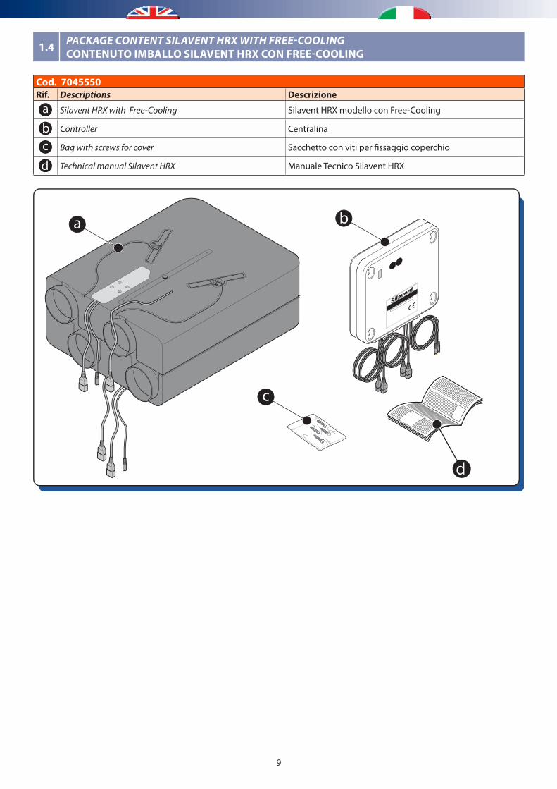
1.4 PACKAGE CONTENT SILAVENT HRX WITH FREE-COOLINGCONTENUTO IMBALLO SILAVENT HRX CON FREE-COOLING
Cod. 7045550Rif. Descriptions Descrizione
Silavent HRX with Free-Cooling Silavent HRX modello con Free-Cooling
Controller Centralina
Bag with screws for cover Sacchetto con viti per fissaggio coperchio
Technical manual Silavent HRX Manuale Tecnico Silavent HRX
10
c
f
g
e
b
b d
d
c
g
h
i
a
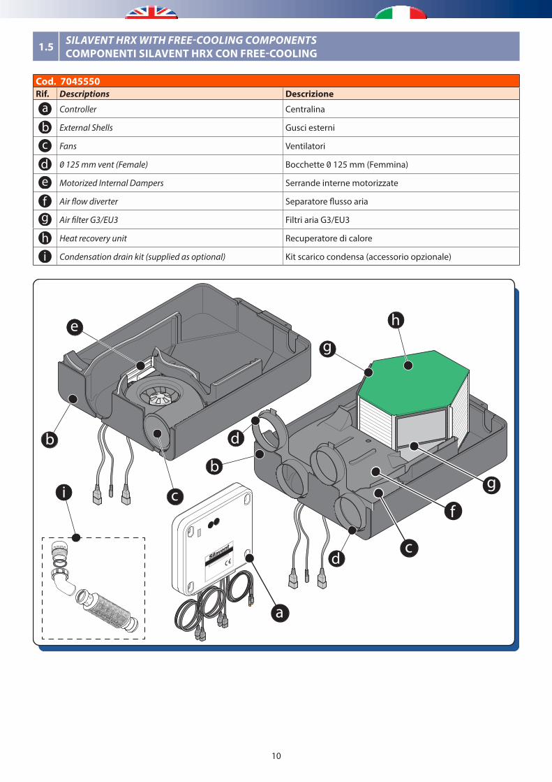
1.5 SILAVENT HRX WITH FREE-COOLING COMPONENTS COMPONENTI SILAVENT HRX CON FREE-COOLING
Cod. 7045550Rif. Descriptions Descrizione
Controller Centralina
External Shells Gusci esterni
Fans Ventilatori
0 125 mm vent (Female) Bocchette 0 125 mm (Femmina)
Motorized Internal Dampers Serrande interne motorizzate
Air flow diverter Separatore flusso aria
Air filter G3/EU3 Filtri aria G3/EU3
Heat recovery unit Recuperatore di calore
i Condensation drain kit (supplied as optional) Kit scarico condensa (accessorio opzionale)
11
MAX 95%
MAX 50°CMIN -25°C
Positioning indicationsIndicazioni di posizionamento
OK!
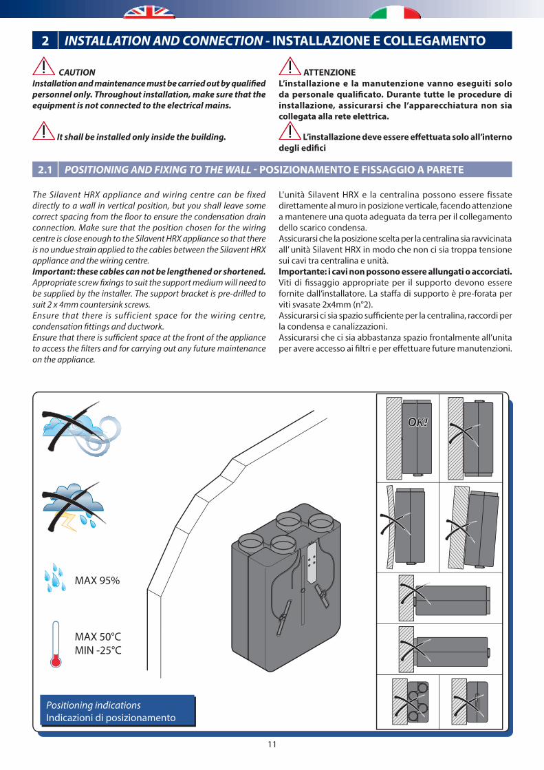
CAUTIONInstallation and maintenance must be carried out by qualified personnel only. Throughout installation, make sure that the equipment is not connected to the electrical mains.
It shall be installed only inside the building.
ATTENZIONEL’installazione e la manutenzione vanno eseguiti solo da personale qualificato. Durante tutte le procedure di installazione, assicurarsi che l’apparecchiatura non sia collegata alla rete elettrica.
L’installazione deve essere effettuata solo all’interno degli edifici
2 INSTALLATION AND CONNECTION - INSTALLAZIONE E COLLEGAMENTO
2.1 POSITIONING AND FIXING TO THE WALL - POSIZIONAMENTO E FISSAGGIO A PARETE
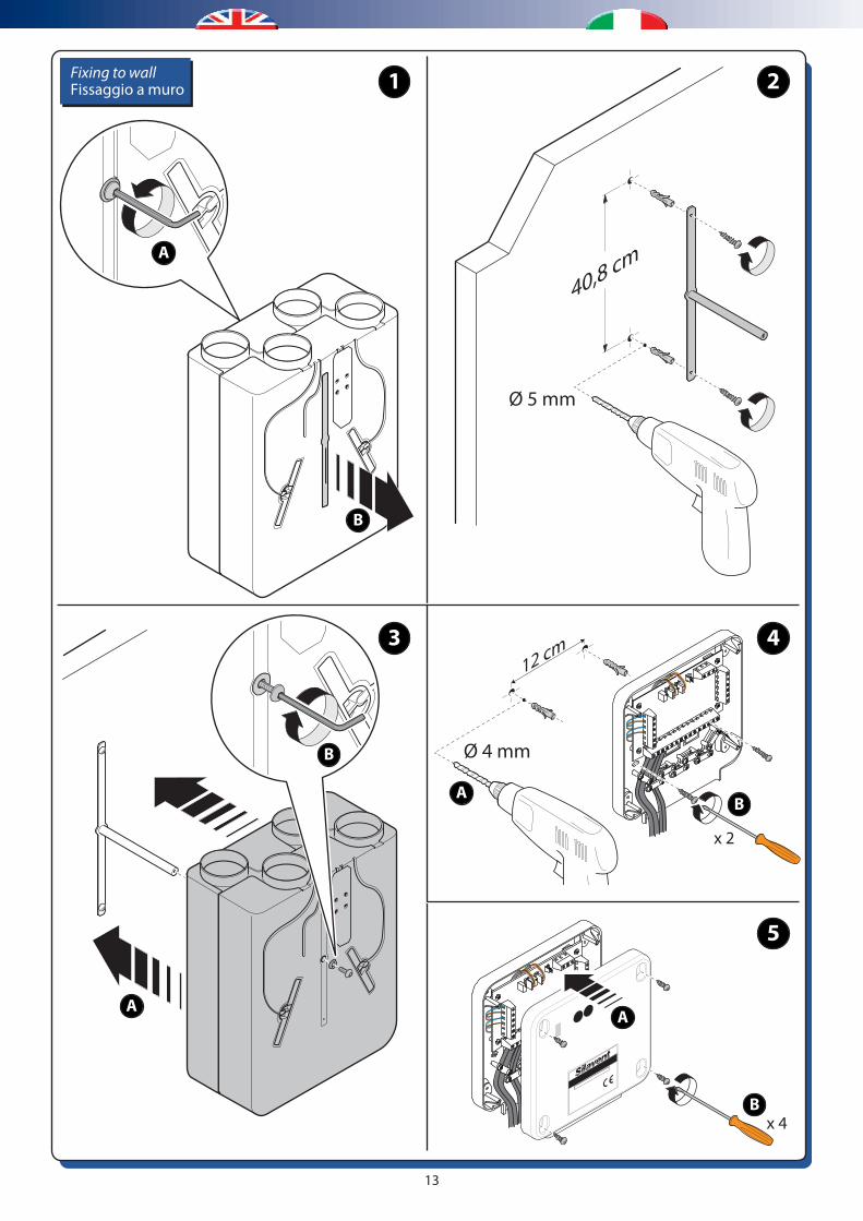
The Silavent HRX appliance and wiring centre can be fixed directly to a wall in vertical position, but you shall leave some correct spacing from the floor to ensure the condensation drain connection. Make sure that the position chosen for the wiring centre is close enough to the Silavent HRX appliance so that there is no undue strain applied to the cables between the Silavent HRX appliance and the wiring centre.Important: these cables can not be lengthened or shortened.Appropriate screw fixings to suit the support medium will need to be supplied by the installer. The support bracket is pre-drilled to suit 2 x 4mm countersink screws.Ensure that there is sufficient space for the wiring centre, condensation fittings and ductwork.Ensure that there is sufficient space at the front of the appliance to access the filters and for carrying out any future maintenance on the appliance.
L’unità Silavent HRX e la centralina possono essere fissate direttamente al muro in posizione verticale, facendo attenzione a mantenere una quota adeguata da terra per il collegamento dello scarico condensa.Assicurarsi che la posizione scelta per la centralina sia ravvicinata all’ unità Silavent HRX in modo che non ci sia troppa tensione sui cavi tra centralina e unità.Importante: i cavi non possono essere allungati o accorciati.Viti di fissaggio appropriate per il supporto devono essere fornite dall’installatore. La staffa di supporto è pre-forata per viti svasate 2x4mm (n°2).Assicurarsi ci sia spazio sufficiente per la centralina, raccordi per la condensa e canalizzazioni.Assicurarsi che ci sia abbastanza spazio frontalmente all’unita per avere accesso ai filtri e per effettuare future manutenzioni.

12
The Silavent HRX appliance can be mounted as a left-hand or right-hand installation, i.e. for convenience the two external duct connections can be either on the left or right-hand side. This feature can be extremely useful in smaller houses or apartments where there is no space to cross over ducts.
IMPORTANT: The configuration selected will determine the connection point for the condensate drain.
When viewed from above, the duct configurations are shown on the diagram below.
L’apparecchio Silavent HRX può essere montato con un installazione a sinistra o a destra, per comodità i due raccordi dei canali esterni possono essere sia sul lato sinistro che destro. Questa caratteristica può essere estremamente utile in case piccole o appartamenti dove non c’è spazio per attraversare i condotti.
IMPORTANTE: La configurazione scelta determinerà il punto di connessione dello scarico condensa
Vista da sopra, la configurazione dei condotti è mostrata nella figura seguente:
A BCD
C DAB
B
D
AOutsideEsterno
InsideInterno
C
DB
COutsideEsterno
InsideInterno
A
Left-hand con�guration - Con�gurazione di sinistra Right-hand con�guration - Con�gurazione di destra
AB
Inlet fresh air from outside / Ingresso aria fresca dall’esterno
Outside / Esterno
Inside / Interno
Supply fresh air to rooms / Immissione aria nelle stanze
CD
Extract stale air from rooms / Estrazione aria viziata dalle stanze
Exhaust stale air to outside / Espulsione aria viziata verso l’esterno
Outside / Esterno
Inside / Interno
Minimum space allowancesesDistanze minime di rispetto
min.
10 cm
min.
60 cm
min.60 cm
min.
10 cm
Note: Leave a 15-cm distance from the ground to install condensation drain kitN.B.: Mantenere distanza da terra di almeno 15 cm per installazione dello scarico condensa
13
B
Ø 5 mm
40,8 cm
Fixing to wallFissaggio a muro 1 2
4
5
3
A
B
A
B
A
Ø 4 mm
AB
12 cm
x 2
x 4
14
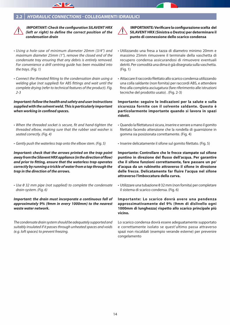
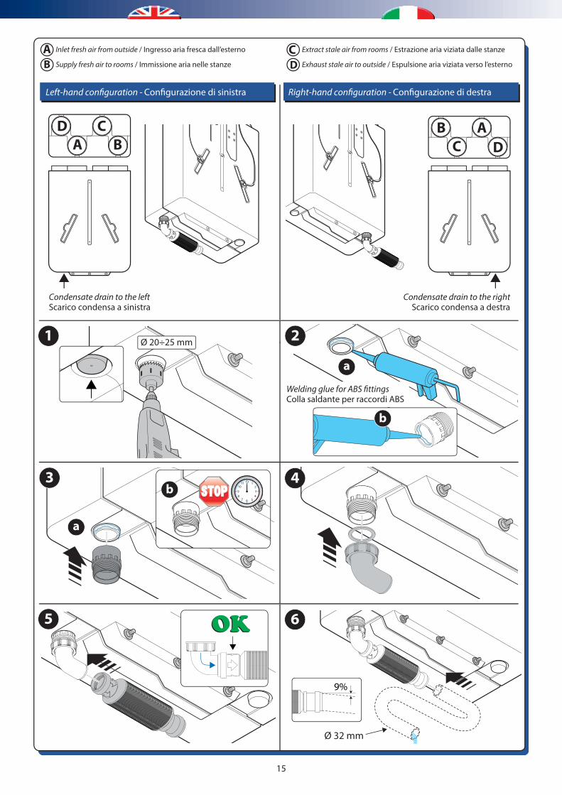
IMPORTANTE: Verificare la configurazione scelta del SILAVENT HRX (Sinistra o Destra) per determinare il punto di connessione dello scarico condensa
• Utilizzando una fresa a tazza di diametro minimo 20mm e massimo 25mm rimuovere il terminale della vaschetta di recupero condensa assicurandosi di rimuovere eventuali detriti. Per comodità una dima è già disegnata sulla vaschetta. (Fig. 1)
• Attaccare il raccordo filettato allo scarico condensa utilizzando una colla saldante (non fornita) per raccordi ABS, e attendere fino alla completa asciugatura (fare riferimento alle istruzioni tecniche del prodotto usato) . (Fig. 2-3)
Importante: seguire le indicazioni per la salute e sulla sicurezza fornite con il solvente saldante. Questo è particolarmente importante quando si lavora in spazi ridotti.
• Quando la filettatura è sicura, inserire e serrare a mano il gomito filettato facendo attenzione che la rondella di guarnizione in gomma sia posizionata correttamente. (Fig. 4)
• Inserire delicatamente il sifone sul gomito filettato. (Fig. 5)
Importante: Controllare che le frecce stampate sul sifone puntino in direzione del flusso dell’acqua. Per garantire che il sifone funzioni correttamente, fare passare un po’ d’acqua da un rubinetto attraverso il sifone in direzione delle frecce. Delicatamente far fluire l’acqua nel sifone attraverso l’imboccatura della curva.
• Utilizzare una tubazione 0 32 mm (non fornita) per completare il sistema di scarico condensa. (Fig. 6)
Importante: Lo scarico dovrà avere una pendenza approssimativamente del 9% (9mm di dislivello ogni 1000mm di lunghezza) rispetto allo scarico principale più vicino.
Lo scarico condensa dovrà essere adeguatamente supportato e correttamente isolato se quest’ultimo passa attraverso spazi non riscaldati (esempio verande esterne) per prevenire congelamento
IMPORTANT: Check the configuration SILAVENT HRX (left or right) to define the correct position of the condensation drain
• Using a hole-saw of minimum diameter 20mm (3/4”) and maximum diameter 25mm (1”), remove the closed end of the condensate tray ensuring that any debris is entirely removed. For convenience a drill centring guide has been moulded into the trays. (Fig. 1)
• Connect the threated fitting to the condensation drain using a welding glue (not supplied) for ABS fittings and wait until the complete drying (refer to technical features of the product). Fig. 2-3
Important: follow the health and safety and user instructions supplied with the solvent weld. This is particularly important when working in confined spaces.
• When the threaded socket is secure, fit and hand-tighten the threaded elbow, making sure that the rubber seal washer is seated correctly. (Fig. 4)
• Gently push the waterless trap onto the elbow stem. (Fig. 5)
Important: check that the arrows printed on the trap point away from the Silavent HRX appliance (in the direction of flow) and prior to fitting, ensure that the waterless trap operates correctly by running a trickle of water from a tap through the trap in the direction of the arrows.
• Use 0 32 mm pipe (not supplied) to complete the condensate drain-system. (Fig. 6)
Important: the drain must incorporate a continuous fall of approximately 9% (9mm in every 1000mm) to the nearest waste water network.
The condensate drain system should be adequately supported and suitably insulated if it passes through unheated spaces and voids (e.g. loft spaces) to prevent freezing.
2.2 HYDRAULIC CONNECTIONS - COLLEGAMENTI IDRAULICI
15
Left-hand con�guration - Con�gurazione di sinistra Right-hand con�guration - Con�gurazione di destra
AB
1
6
Inlet fresh air from outside / Ingresso aria fresca dall’esterno
Supply fresh air to rooms / Immissione aria nelle stanze
CD
Extract stale air from rooms / Estrazione aria viziata dalle stanze
Exhaust stale air to outside / Espulsione aria viziata verso l’esterno
Condensate drain to the leftScarico condensa a sinistra
Condensate drain to the rightScarico condensa a destra
A BCD
C DAB
43
a
b
2Ø 20÷25 mm
5
Ø 32 mm
9%
12 1234
5678910
11
a
b
Welding glue for ABS �ttingsColla saldante per raccordi ABS
16
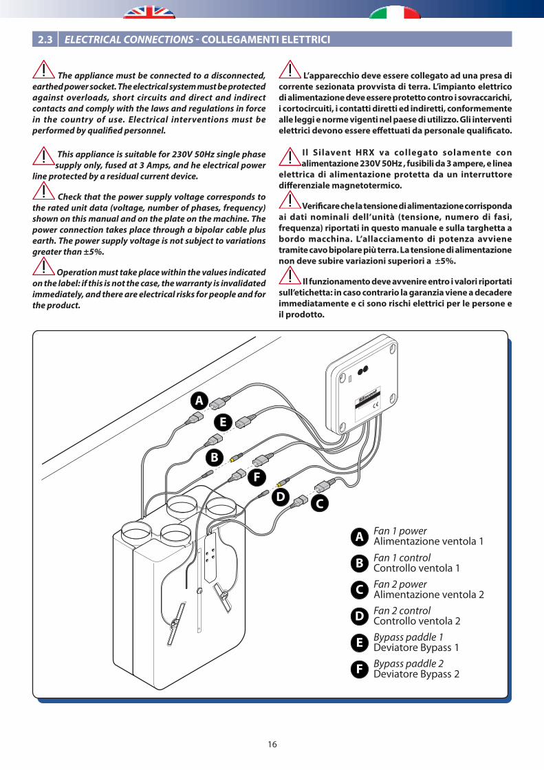
L’apparecchio deve essere collegato ad una presa di corrente sezionata provvista di terra. L’impianto elettrico di alimentazione deve essere protetto contro i sovraccarichi, i cortocircuiti, i contatti diretti ed indiretti, conformemente alle leggi e norme vigenti nel paese di utilizzo. Gli interventi elettrici devono essere effettuati da personale qualificato.
Il Silavent HRX va collegato solamente con alimentazione 230V 50Hz , fusibili da 3 ampere, e linea
elettrica di alimentazione protetta da un interruttore differenziale magnetotermico.
Verificare che la tensione di alimentazione corrisponda ai dati nominali dell’unità (tensione, numero di fasi, frequenza) riportati in questo manuale e sulla targhetta a bordo macchina. L’allacciamento di potenza avviene tramite cavo bipolare più terra. La tensione di alimentazione non deve subire variazioni superiori a ±5%.
Il funzionamento deve avvenire entro i valori riportati sull’etichetta: in caso contrario la garanzia viene a decadere immediatamente e ci sono rischi elettrici per le persone e il prodotto.
The appliance must be connected to a disconnected, earthed power socket. The electrical system must be protected against overloads, short circuits and direct and indirect contacts and comply with the laws and regulations in force in the country of use. Electrical interventions must be performed by qualified personnel.
This appliance is suitable for 230V 50Hz single phase supply only, fused at 3 Amps, and he electrical power
line protected by a residual current device.
Check that the power supply voltage corresponds to the rated unit data (voltage, number of phases, frequency) shown on this manual and on the plate on the machine. The power connection takes place through a bipolar cable plus earth. The power supply voltage is not subject to variations greater than ±5%.
Operation must take place within the values indicated on the label: if this is not the case, the warranty is invalidated immediately, and there are electrical risks for people and for the product.
2.3 ELECTRICAL CONNECTIONS - COLLEGAMENTI ELETTRICI
A
B
E
C
A
B
C
D
Fan 1 powerAlimentazione ventola 1Fan 1 controlControllo ventola 1Fan 2 powerAlimentazione ventola 2Fan 2 controlControllo ventola 2
E
F
Bypass paddle 1Deviatore Bypass 1Bypass paddle 2 Deviatore Bypass 2
FD
17
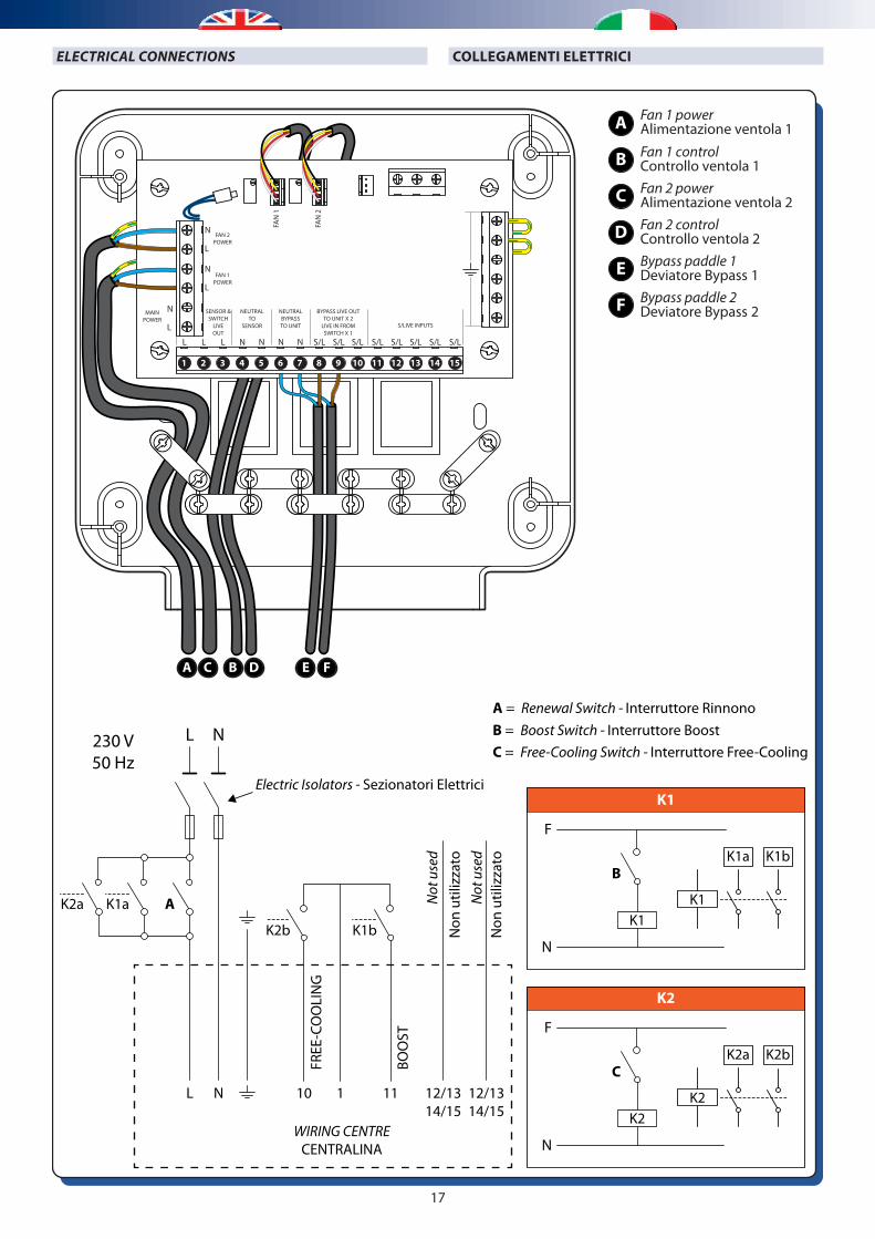
COLLEGAMENTI ELETTRICIELECTRICAL CONNECTIONS
A C B D E F
1 15141312111098765432
K1
F
N
Electric Isolators - Sezionatori Elettrici
BOO
ST
K1b Non
util
izza
toN
ot u
sed
Non
util
izza
toN
ot u
sed
K1a A
B
A = Renewal Switch - Interruttore RinnonoB = Boost Switch - Interruttore BoostC = Free-Cooling Switch - Interruttore Free-Cooling
K2a
L
L
N
N
FREE
-CO
OLI
NG
K2b
11 12/1314/15
12/1314/15
110
WIRING CENTRECENTRALINA
K1K1
K1bK1a
K2
F
N
C
K2K2
K2bK2a
A
B
C
D
Fan 1 powerAlimentazione ventola 1Fan 1 controlControllo ventola 1Fan 2 powerAlimentazione ventola 2Fan 2 controlControllo ventola 2
E
F
Bypass paddle 1Deviatore Bypass 1Bypass paddle 2 Deviatore Bypass 2
N
L
MAINPOWER
FAN 2POWER
FAN 1POWER
S/LIVE INPUTS
BYPASS LIVE OUTTO UNIT X 2
LIVE IN FROMSWITCH X 1
NEUTRALBYPASSTO UNIT
NEUTRALTO
SENSOR
SENSOR &SWITCH
LIVEOUT
FAN
1
FAN
2
N
L
L L L N N N N S/L S/L S/L S/L S/L S/L S/L S/L
N
L
230 V50 Hz
18
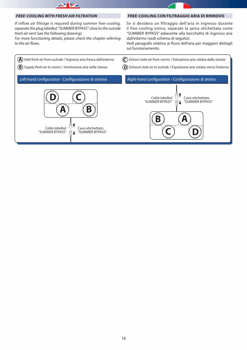
FREE-COOLING CON FILTRAGGIO ARIA DI RINNOVOFREE-COOLING WITH FRESH AIR FILTRATION
Cable labelled“SUMMER BYPASS”
Cavo etichettato“SUMMER BYPASS”
Cable labelled“SUMMER BYPASS”
Cavo etichettato“SUMMER BYPASS”
Left-hand con�guration - Con�gurazione di sinistra Right-hand con�guration - Con�gurazione di destra
AB
Inlet fresh air from outside / Ingresso aria fresca dall’esterno
Supply fresh air to rooms / Immissione aria nelle stanze
CD
Extract stale air from rooms / Estrazione aria viziata dalle stanze
Exhaust stale air to outside / Espulsione aria viziata verso l’esterno
A BCD
C DAB
If inflow air filtrage is required during summer free-cooling, separate the plug labelled “SUMMER BYPASS” close to the outside fresh air vent (see the following drawing).For more functioning details, please check the chapter referring to the air flows.
Se si desidera un filtraggio dell’aria in ingresso durante il free-cooling estivo, separate la spina etichettata come “SUMMER BYPASS” adiacente alla bocchetta di ingresso aria dall’esterno (vedi schema di seguito).Vedi paragrafo relativo ai flussi dell’aria per maggiori dettagli sul funzionamento.
19
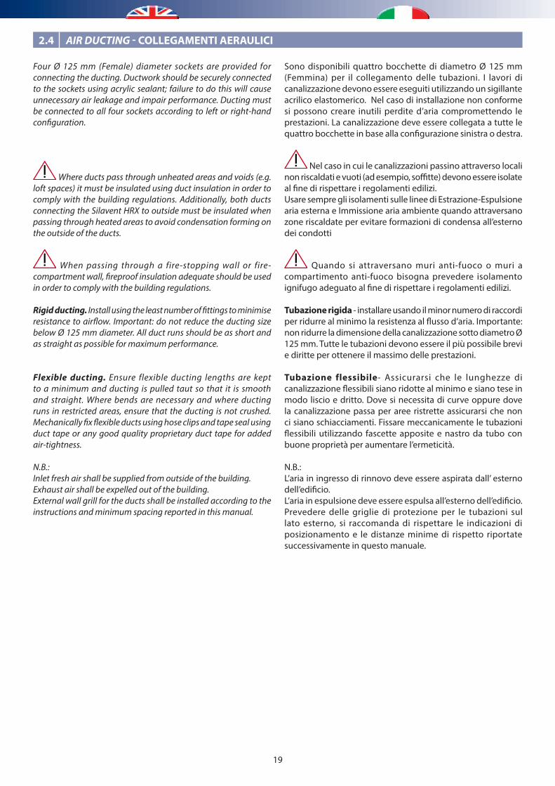
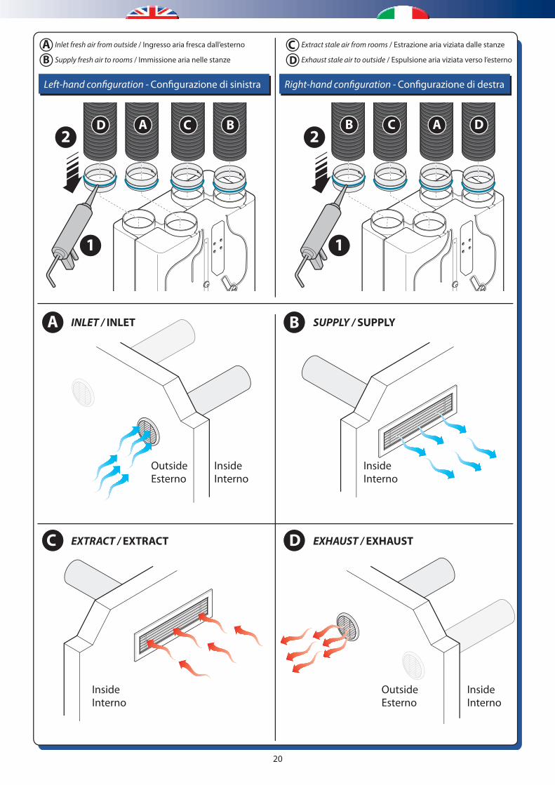
Four Ø 125 mm (Female) diameter sockets are provided for connecting the ducting. Ductwork should be securely connected to the sockets using acrylic sealant; failure to do this will cause unnecessary air leakage and impair performance. Ducting must be connected to all four sockets according to left or right-hand configuration.
Where ducts pass through unheated areas and voids (e.g. loft spaces) it must be insulated using duct insulation in order to comply with the building regulations. Additionally, both ducts connecting the Silavent HRX to outside must be insulated when passing through heated areas to avoid condensation forming on the outside of the ducts.
When passing through a fire-stopping wall or fire-compartment wall, fireproof insulation adequate should be used in order to comply with the building regulations.
Rigid ducting. Install using the least number of fittings to minimise resistance to airflow. Important: do not reduce the ducting size below Ø 125 mm diameter. All duct runs should be as short and as straight as possible for maximum performance.
Flexible ducting. Ensure flexible ducting lengths are kept to a minimum and ducting is pulled taut so that it is smooth and straight. Where bends are necessary and where ducting runs in restricted areas, ensure that the ducting is not crushed. Mechanically fix flexible ducts using hose clips and tape seal using duct tape or any good quality proprietary duct tape for added air-tightness.
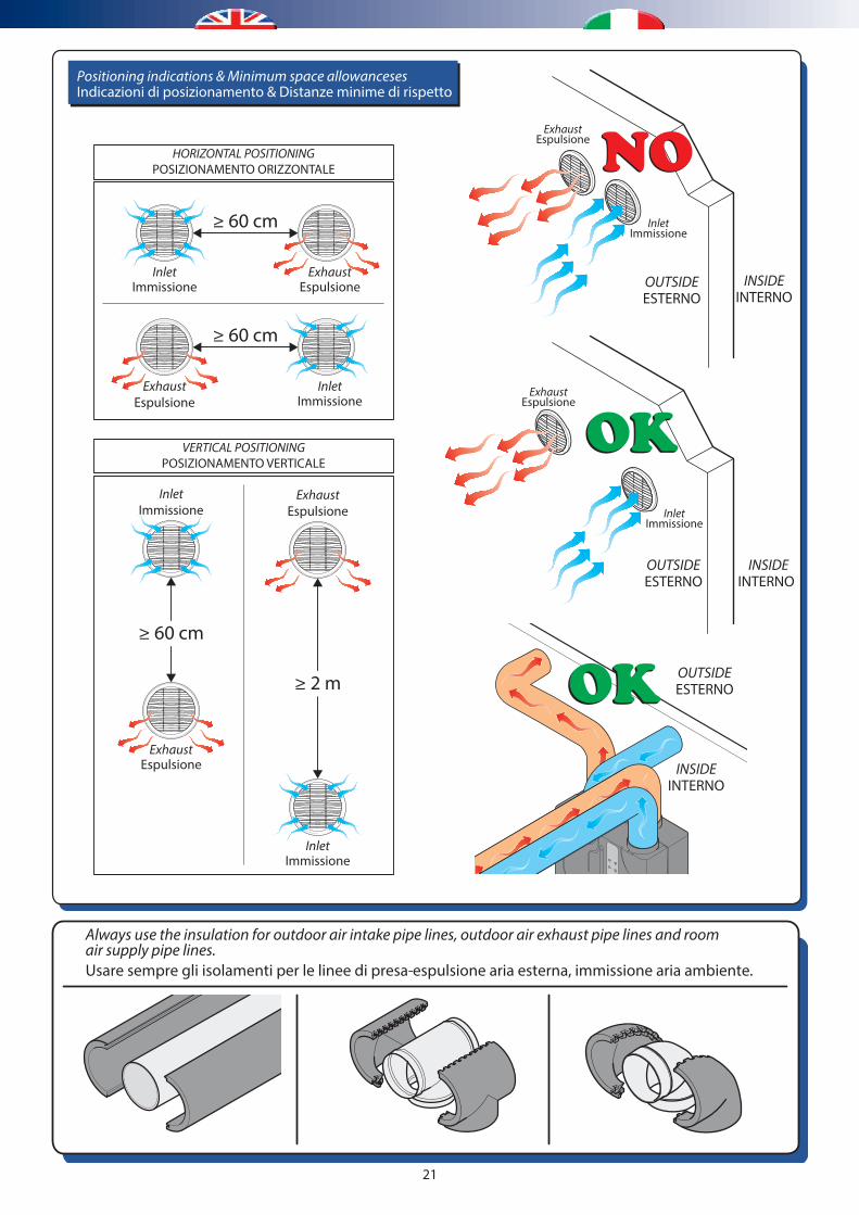
N.B.:Inlet fresh air shall be supplied from outside of the building.Exhaust air shall be expelled out of the building.External wall grill for the ducts shall be installed according to the instructions and minimum spacing reported in this manual.
Sono disponibili quattro bocchette di diametro Ø 125 mm (Femmina) per il collegamento delle tubazioni. I lavori di canalizzazione devono essere eseguiti utilizzando un sigillante acrilico elastomerico. Nel caso di installazione non conforme si possono creare inutili perdite d’aria compromettendo le prestazioni. La canalizzazione deve essere collegata a tutte le quattro bocchette in base alla configurazione sinistra o destra.
Nel caso in cui le canalizzazioni passino attraverso locali non riscaldati e vuoti (ad esempio, soffitte) devono essere isolate al fine di rispettare i regolamenti edilizi.Usare sempre gli isolamenti sulle linee di Estrazione-Espulsione aria esterna e Immissione aria ambiente quando attraversano zone riscaldate per evitare formazioni di condensa all’esterno dei condotti
Quando si attraversano muri anti-fuoco o muri a compartimento anti-fuoco bisogna prevedere isolamento ignifugo adeguato al fine di rispettare i regolamenti edilizi.
Tubazione rigida - installare usando il minor numero di raccordi per ridurre al minimo la resistenza al flusso d’aria. Importante: non ridurre la dimensione della canalizzazione sotto diametro Ø 125 mm. Tutte le tubazioni devono essere il più possibile brevi e diritte per ottenere il massimo delle prestazioni.
Tubazione flessibile- Assicurarsi che le lunghezze di canalizzazione flessibili siano ridotte al minimo e siano tese in modo liscio e dritto. Dove si necessita di curve oppure dove la canalizzazione passa per aree ristrette assicurarsi che non ci siano schiacciamenti. Fissare meccanicamente le tubazioni flessibili utilizzando fascette apposite e nastro da tubo con buone proprietà per aumentare l’ermeticità.
N.B.:L’aria in ingresso di rinnovo deve essere aspirata dall’ esterno dell’edificio.L’aria in espulsione deve essere espulsa all’esterno dell’edificio.Prevedere delle griglie di protezione per le tubazioni sul lato esterno, si raccomanda di rispettare le indicazioni di posizionamento e le distanze minime di rispetto riportate successivamente in questo manuale.
2.4 AIR DUCTING - COLLEGAMENTI AERAULICI
20
D
A
1
2
B
C D
A C B
OutsideEsterno
InsideInterno
InsideInterno
OutsideEsterno
Inside
EXHAUST / EXHAUSTEXTRACT / EXTRACT
SUPPLY / SUPPLYINLET / INLET
InternoInsideInterno
B
1
2C A D
Right-hand con�guration - Con�gurazione di destraLeft-hand con�guration - Con�gurazione di sinistra
AB
Inlet fresh air from outside / Ingresso aria fresca dall’esterno
Supply fresh air to rooms / Immissione aria nelle stanze
CD
Extract stale air from rooms / Estrazione aria viziata dalle stanze
Exhaust stale air to outside / Espulsione aria viziata verso l’esterno
21
Usare sempre gli isolamenti per le linee di presa-espulsione aria esterna, immissione aria ambiente.
Always use the insulation for outdoor air intake pipe lines, outdoor air exhaust pipe lines and roomair supply pipe lines.
Positioning indications & Minimum space allowancesesIndicazioni di posizionamento & Distanze minime di rispetto
InletImmissione
HORIZONTAL POSITIONINGPOSIZIONAMENTO ORIZZONTALE
VERTICAL POSITIONINGPOSIZIONAMENTO VERTICALE
ExhaustEspulsione
ExhaustEspulsione
InletImmissione
ExhaustEspulsione
InletImmissione
InletImmissione
ExhaustEspulsione
INSIDEINTERNO
OUTSIDEESTERNO
ExhaustEspulsione
InletImmissione
OUTSIDEESTERNO
InletImmissione
ExhaustEspulsione
INSIDEINTERNO
≥ 60 cm
≥ 60 cm
≥ 2 m
≥ 60 cm
INSIDEINTERNO
OUTSIDEESTERNO
22
Quando tutte le connessioni elettriche sono state controllate, accendete l’unità e verificate che il sistema funzioni correttamente. L’unità dovrebbe modificare da velocità bassa (Low) a Boost tramite l’interruttore dedicato.La portata d’aria deve essere regolata in ogni valvola di taratura nelle singole stanze in modo da bilanciare il sistema.La misurazione della portata d’aria (m3/h) deve essere eseguita tramite una apparecchiatura di rilevamento di portata d’aria e i risultati devono essere confrontati e allineati con i dati di progetto. Il metodo più comune prevede l’utilizzo di un anemometro, o simile, collocato in modo da ricoprire completamente la bocchetta per misurare la portata d’aria in espulsione o immissione.
BILANCIAMENTO DEL SISTEMA
Prima di iniziare le operazioni di bilanciamento, si prega di chiudere completamente tutte le porte e finestre interne ed esterne.
• Apertura completa di tutte le bocchette. (Fig. 1)• Accendere l’unità e attivare la modalità Boost tramite
l’interruttore dedicato. (Fig. 2)• Misurare il volume totale di aria estratta sulla bocchetta di
estrazione posta all’esterno dell’edificio. (Fig. 3)• Rimuovere il tappo in plastica della centralina e, utilizzando
un piccolo cacciavite, modificare la portata d’aria agendo sul “Controllo velocità BOOST” (vedi regolazioni centralina) fino a raggiungere il valore di volume totale estrazione da progetto. (Fig. 4-5)
• Tarare le singole bocchette di estrazione fino a raggiungere i dati di progetto. (Fig. 6)
• Impostare la modalità in LOW (disattivando il Boost tramite l’interruttore dedicato). (Fig. 7)
• Misurare il volume totale di aria sulla bocchetta di immissione posta all’esterno dell’edificio. (Fig. 8)
• Rimuovere il tappo in plastica e utilizzando un piccolo cacciavite modificare la portata d’aria agendo sul “Controllo velocità bassa LOW” fino a raggiungere il valore di volume totale in immissione da progetto. (Fig. 9-10)
• Tarare le singole bocchette di immissione fino a raggiungere i dati di progetto. (Fig. 11)
• Re inserite i tappi in plastica sulla centralina. (Fig. 12)
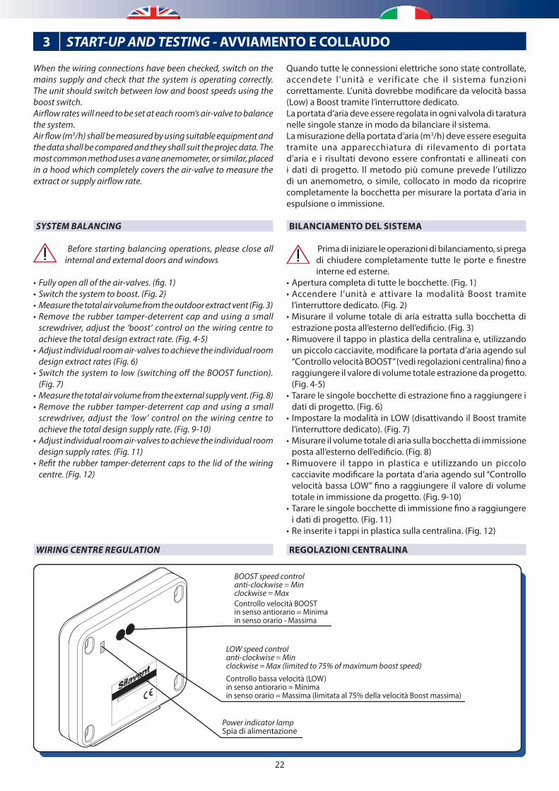
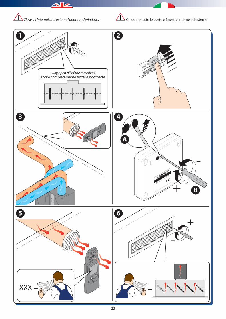
When the wiring connections have been checked, switch on the mains supply and check that the system is operating correctly. The unit should switch between low and boost speeds using the boost switch.Airflow rates will need to be set at each room’s air-valve to balance the system.Air flow (m3/h) shall be measured by using suitable equipment and the data shall be compared and they shall suit the projec data. The most common method uses a vane anemometer, or similar, placed in a hood which completely covers the air-valve to measure the extract or supply airflow rate.
SYSTEM BALANCING
Before starting balancing operations, please close all internal and external doors and windows
• Fully open all of the air-valves. (fig. 1)• Switch the system to boost. (Fig. 2)• Measure the total air volume from the outdoor extract vent (Fig. 3)• Remove the rubber tamper-deterrent cap and using a small
screwdriver, adjust the ‘boost’ control on the wiring centre to achieve the total design extract rate. (Fig. 4-5)
• Adjust individual room air-valves to achieve the individual room design extract rates (Fig. 6)
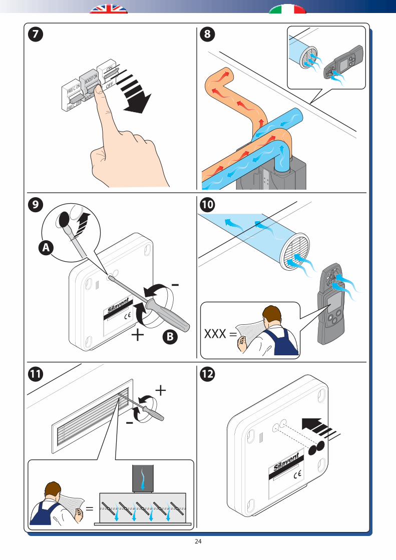
• Switch the system to low (switching off the BOOST function). (Fig. 7)
• Measure the total air volume from the external supply vent. (Fig. 8)• Remove the rubber tamper-deterrent cap and using a small
screwdriver, adjust the ‘low’ control on the wiring centre to achieve the total design supply rate. (Fig. 9-10)
• Adjust individual room air-valves to achieve the individual room design supply rates. (Fig. 11)
• Refit the rubber tamper-deterrent caps to the lid of the wiring centre. (Fig. 12)
Power indicator lampSpia di alimentazione
LOW speed controlanti-clockwise = Minclockwise = Max (limited to 75% of maximum boost speed)
Controllo bassa velocità (LOW)in senso antiorario = Minimain senso orario = Massima (limitata al 75% della velocità Boost massima)
BOOST speed controlanti-clockwise = Minclockwise = Max Controllo velocità BOOSTin senso antiorario = Minimain senso orario - Massima
REGOLAZIONI CENTRALINAWIRING CENTRE REGULATION
3 START-UP AND TESTING - AVVIAMENTO E COLLAUDO
23
1 2
3 4
5 6
Fully open all of the air valvesAprire completamente tutte le bocchette
ON
OFFBOOST ON
BOOST OFFFREE C. ON
FREE C. OFF
Mode
XXX =
+
-
=
Mod
e
B
-
A
+
Chiudere tutte le porte e finestre interne ed esterne Close all internal and external doors and windows
24
7 8
9 10
11 12
ON
OFFBOOST ON
BOOST OFFFREE C. ON
FREE C. OFF
+
+
-
=
Mode
XXX = M
ode
B
-A
25
4 FUNCTIONING - FUNZIONAMENTO
Right-hand con�guration - Con�gurazione di destraLeft-hand con�guration - Con�gurazione di sinistra
AB
Fresh air inlet from outside / Ingresso aria fresca dall’esterno
Supply fresh air into the rooms / Immissione aria nelle stanze
CD
Extract stale air from the rooms / Estrazione aria viziata dalle stanze
Exhaust stale air out of the building / Espulsione aria viziata verso l’esterno
BAD C
A BCD
DCB A
C DAB
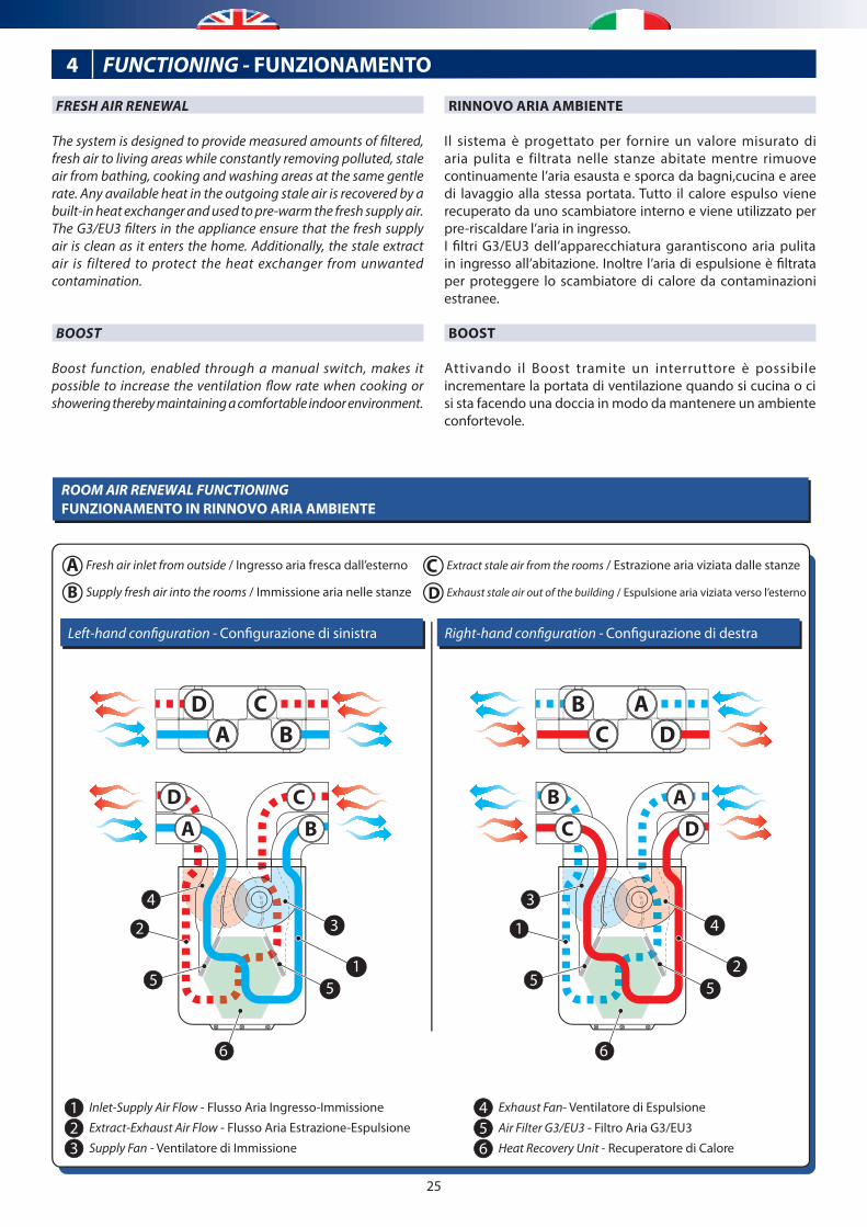
1 Inlet-Supply Air Flow - Flusso Aria Ingresso-Immissione
2 Extract-Exhaust Air Flow - Flusso Aria Estrazione-Espulsione
3 Supply Fan - Ventilatore di Immissione
4 Exhaust Fan- Ventilatore di Espulsione
5 Air Filter G3/EU3 - Filtro Aria G3/EU3
6 Heat Recovery Unit - Recuperatore di Calore
6
2
51
3
2
4
5
6
55
4
1
3
ROOM AIR RENEWAL FUNCTIONINGFUNZIONAMENTO IN RINNOVO ARIA AMBIENTE
FRESH AIR RENEWAL
The system is designed to provide measured amounts of filtered, fresh air to living areas while constantly removing polluted, stale air from bathing, cooking and washing areas at the same gentle rate. Any available heat in the outgoing stale air is recovered by a built-in heat exchanger and used to pre-warm the fresh supply air.The G3/EU3 filters in the appliance ensure that the fresh supply air is clean as it enters the home. Additionally, the stale extract air is filtered to protect the heat exchanger from unwanted contamination.
BOOST
Boost function, enabled through a manual switch, makes it possible to increase the ventilation flow rate when cooking or showering thereby maintaining a comfortable indoor environment.
RINNOVO ARIA AMBIENTE
Il sistema è progettato per fornire un valore misurato di aria pulita e filtrata nelle stanze abitate mentre rimuove continuamente l’aria esausta e sporca da bagni,cucina e aree di lavaggio alla stessa portata. Tutto il calore espulso viene recuperato da uno scambiatore interno e viene utilizzato per pre-riscaldare l’aria in ingresso.I filtri G3/EU3 dell’apparecchiatura garantiscono aria pulita in ingresso all’abitazione. Inoltre l’aria di espulsione è filtrata per proteggere lo scambiatore di calore da contaminazioni estranee.
BOOST
Attivando il Boost tramite un interruttore è possibile incrementare la portata di ventilazione quando si cucina o ci si sta facendo una doccia in modo da mantenere un ambiente confortevole.
26
FREE-COOLING FUNCTIONING
Right-hand con�guration - Con�gurazione di destraLeft-hand con�guration - Con�gurazione di sinistra
AB
Fresh air inlet from outside / Ingresso aria fresca dall’esterno
Supply fresh air into the rooms / Immissione aria nelle stanze
CD
Extract stale air from the rooms / Estrazione aria viziata dalle stanze
Exhaust stale air out of the building / Espulsione aria viziata verso l’esterno
BAD C
DCB A
AB
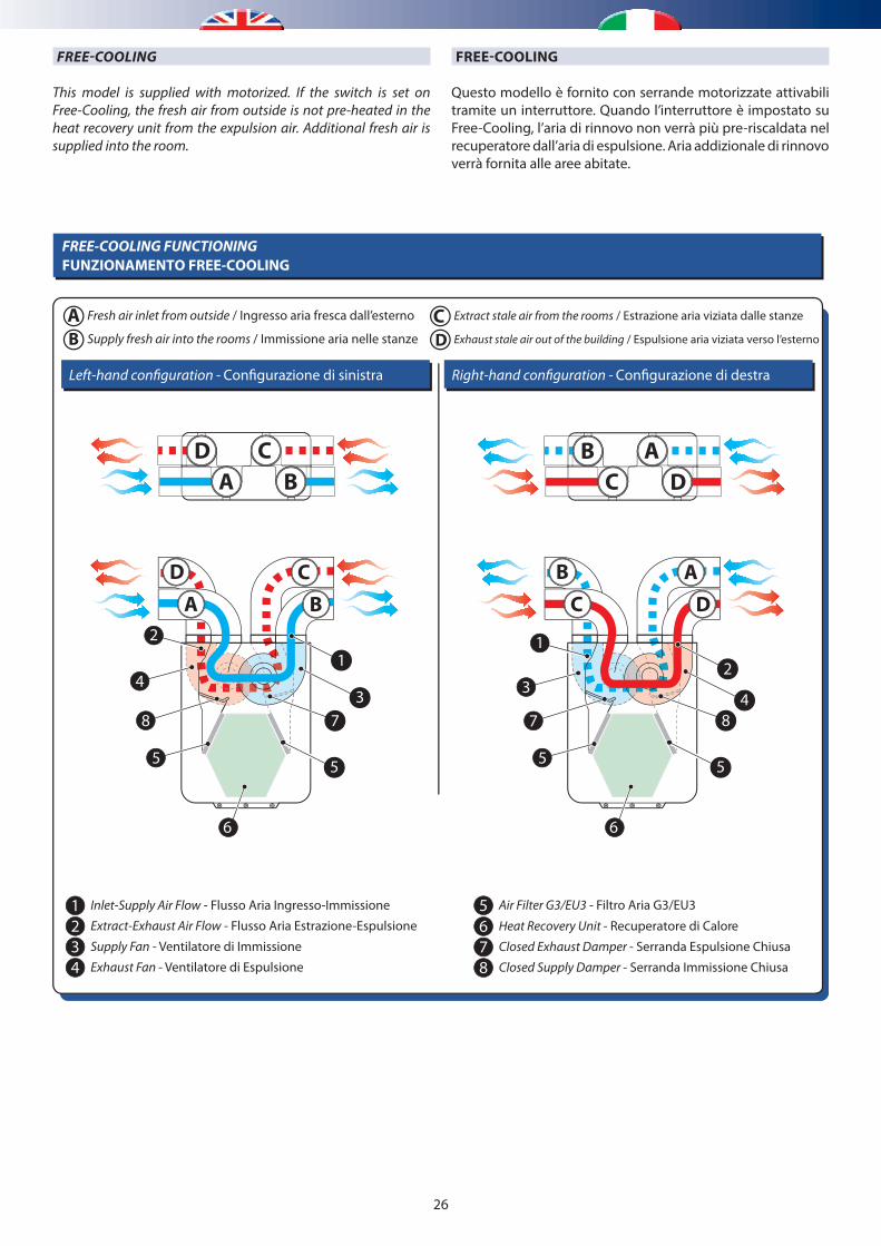
1 Inlet-Supply Air Flow - Flusso Aria Ingresso-Immissione
2 Extract-Exhaust Air Flow - Flusso Aria Estrazione-Espulsione
3 Supply Fan - Ventilatore di Immissione
5 Air Filter G3/EU3 - Filtro Aria G3/EU3
6 Heat Recovery Unit - Recuperatore di Calore
7 Closed Exhaust Damper - Serranda Espulsione Chiusa
4 Exhaust Fan - Ventilatore di Espulsione 8 Closed Supply Damper - Serranda Immissione Chiusa
C D
FUNZIONAMENTO FREE-COOLING
1
5
4
2
8
5
3
7
66
B2
5
3
1
7
5
4
8
CDA
FREE-COOLING
This model is supplied with motorized. If the switch is set on Free-Cooling, the fresh air from outside is not pre-heated in the heat recovery unit from the expulsion air. Additional fresh air is supplied into the room.
FREE-COOLING
Questo modello è fornito con serrande motorizzate attivabili tramite un interruttore. Quando l’interruttore è impostato su Free-Cooling, l’aria di rinnovo non verrà più pre-riscaldata nel recuperatore dall’aria di espulsione. Aria addizionale di rinnovo verrà fornita alle aree abitate.
27
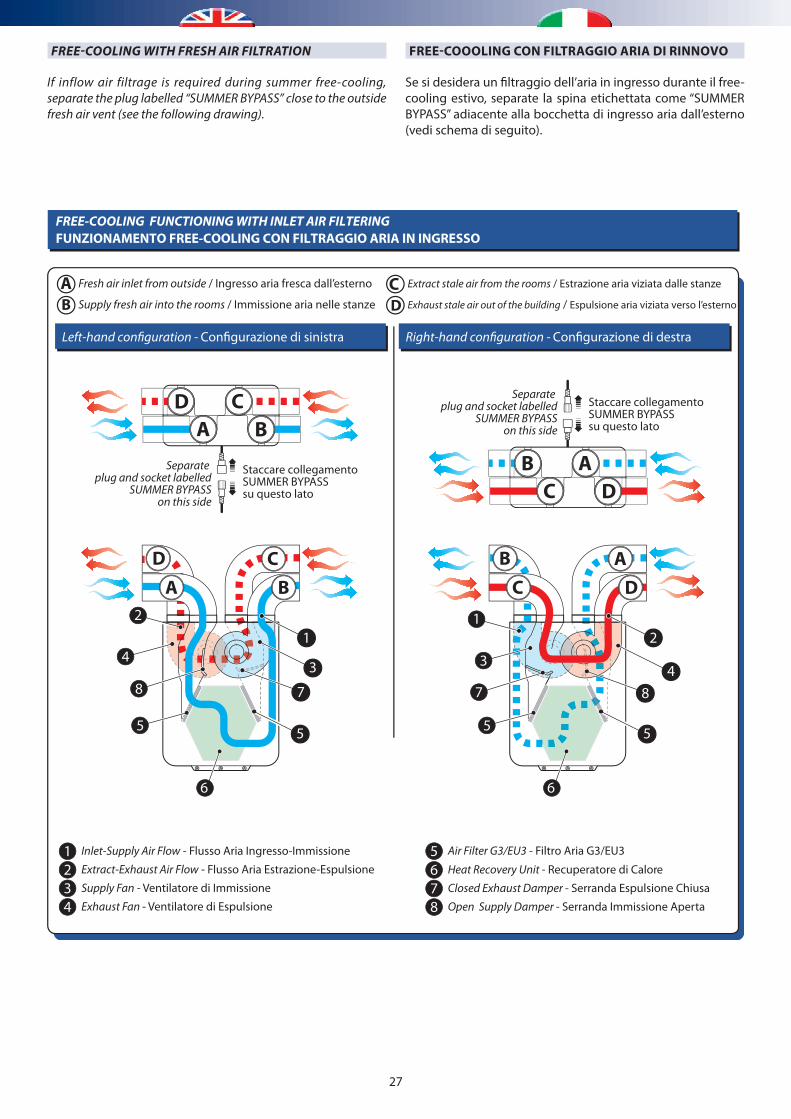
FREE-COOLING FUNCTIONING WITH INLET AIR FILTERING
Right-hand con�guration - Con�gurazione di destraLeft-hand con�guration - Con�gurazione di sinistra
AB
Fresh air inlet from outside / Ingresso aria fresca dall’esterno
Supply fresh air into the rooms / Immissione aria nelle stanze
CD
Extract stale air from the rooms / Estrazione aria viziata dalle stanze
Exhaust stale air out of the building / Espulsione aria viziata verso l’esterno
BAD C
A BCD
DCB A
AB
1 Inlet-Supply Air Flow - Flusso Aria Ingresso-Immissione
2 Extract-Exhaust Air Flow - Flusso Aria Estrazione-Espulsione
3 Supply Fan - Ventilatore di Immissione
5 Air Filter G3/EU3 - Filtro Aria G3/EU3
6 Heat Recovery Unit - Recuperatore di Calore
7 Closed Exhaust Damper - Serranda Espulsione Chiusa
4 Exhaust Fan - Ventilatore di Espulsione 8 Open Supply Damper - Serranda Immissione Aperta
C D
Staccare collegamentoSUMMER BYPASSsu questo lato
Separate plug and socket labelled
SUMMER BYPASSon this side
Staccare collegamentoSUMMER BYPASSsu questo lato
Separate plug and socket labelled
SUMMER BYPASSon this side
FUNZIONAMENTO FREE-COOLING CON FILTRAGGIO ARIA IN INGRESSO
1
5
4
2
8
5
3
7
6
2
5
3
1
7
5
4
8
6
FREE-COOOLING CON FILTRAGGIO ARIA DI RINNOVOFREE-COOLING WITH FRESH AIR FILTRATION
If inflow air filtrage is required during summer free-cooling, separate the plug labelled “SUMMER BYPASS” close to the outside fresh air vent (see the following drawing).
Se si desidera un filtraggio dell’aria in ingresso durante il free-cooling estivo, separate la spina etichettata come “SUMMER BYPASS” adiacente alla bocchetta di ingresso aria dall’esterno (vedi schema di seguito).
28
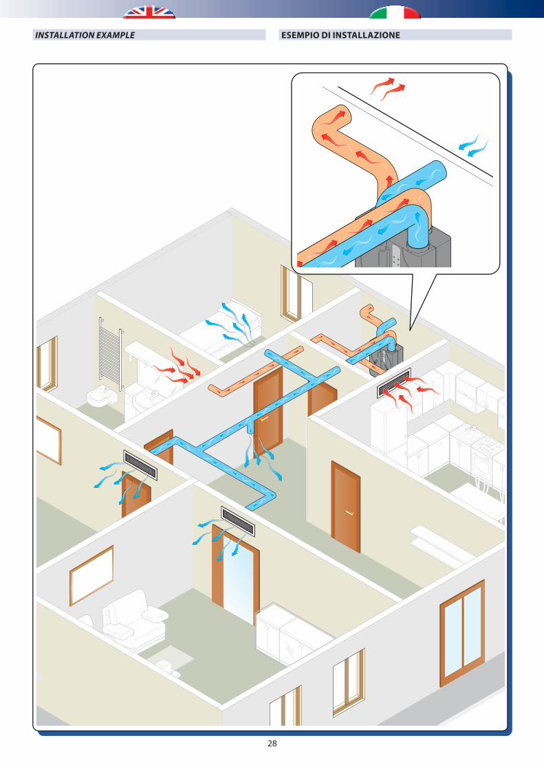
ESEMPIO DI INSTALLAZIONEINSTALLATION EXAMPLE
29
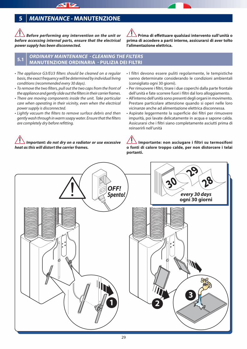
Prima di effettuare qualsiasi intervento sull’unità o prima di accedere a parti interne, assicurarsi di aver tolto l’alimentazione elettrica.
• I filtri devono essere puliti regolarmente, le tempistiche vanno determinate considerando le condizioni ambientali (consigliato ogni 30 giorni).
• Per rimuovere i filtri, tirare i due coperchi dalla parte frontale dell’unità e fate scorrere fuori i filtri dal loro alloggiamento.
• All’interno dell’unità sono presenti degli organi in movimento. Prestare particolare attenzione quando si operi nelle loro vicinanze anche ad alimentazione elettrica disconnessa.
• Aspirate leggermente la superficie dei filtri per rimuovere impurità, poi lavate delicatamente in acqua e sapone calda. Assicurarsi che i filtri siano completamente asciutti prima di reinserirli nell’unità
Importante: non asciugare i filtri su termosifoni o fonti di calore troppo calde, per non distorcere i telai portanti.
Before performing any intervention on the unit or before accessing internal parts, ensure that the electrical power supply has been disconnected.
• The appliance G3/EU3 filters should be cleaned on a regular basis, the exact frequency will be determined by individual living conditions (recommended every 30 days).
• To remove the two filters, pull out the two caps from the front of the appliance and gently slide out the filters in their carrier frames.
• There are moving components inside the unit. Take particular care when operating in their vicinity, even when the electrical power supply is disconnected.
• Lightly vacuum the filters to remove surface debris and then gently wash through in warm soapy water. Ensure that the filters are completely dry before refitting.
Important: do not dry on a radiator or use excessive heat as this will distort the carrier frames.
every 30 daysogni 30 giorni
OFF!Spento!
283029
1 23
5 MAINTENANCE - MANUTENZIONE
5.1 ORDINARY MAINTENANCE - CLEANING THE FILTERSMANUTENZIONE ORDINARIA - PULIZIA DEI FILTRI
30
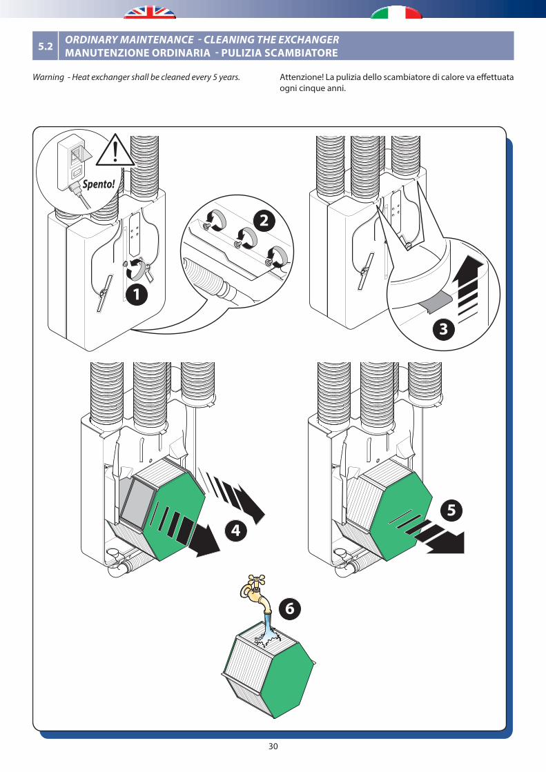
Attenzione! La pulizia dello scambiatore di calore va effettuata ogni cinque anni.
Warning - Heat exchanger shall be cleaned every 5 years.
Spento!
1
2
3
6
45
5.2 ORDINARY MAINTENANCE - CLEANING THE EXCHANGERMANUTENZIONE ORDINARIA - PULIZIA SCAMBIATORE
31
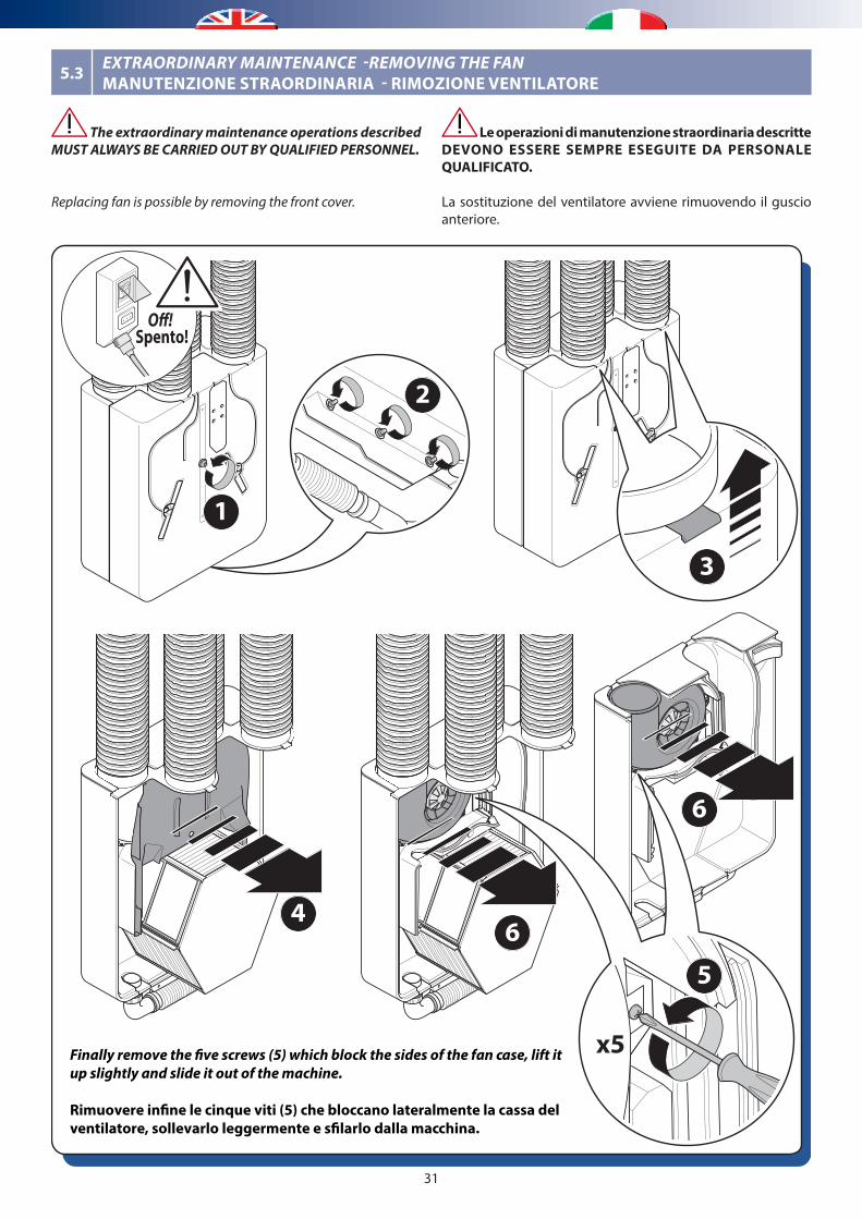
Finally remove the �ve screws (5) which block the sides of the fan case, lift it up slightly and slide it out of the machine.
Rimuovere in�ne le cinque viti (5) che bloccano lateralmente la cassa del ventilatore, sollevarlo leggermente e s�larlo dalla macchina.
Spento!O�!
1
2
3
46
6
5
x5
5.3 EXTRAORDINARY MAINTENANCE -REMOVING THE FANMANUTENZIONE STRAORDINARIA - RIMOZIONE VENTILATORE
Le operazioni di manutenzione straordinaria descritte DEVONO ESSERE SEMPRE ESEGUITE DA PERSONALE QUALIFICATO.
La sostituzione del ventilatore avviene rimuovendo il guscio anteriore.
The extraordinary maintenance operations described MUST ALWAYS BE CARRIED OUT BY QUALIFIED PERSONNEL.
Replacing fan is possible by removing the front cover.
32
[mm]
282
564 29083 11
661
8755
212
133
86
Ø 125
733
700
109
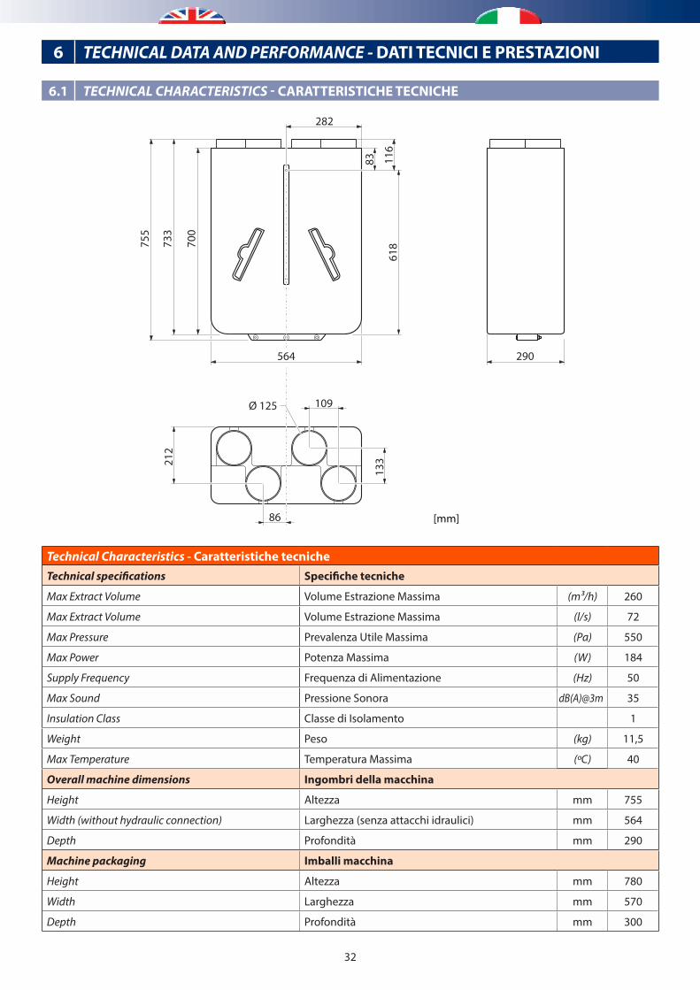
Technical Characteristics - Caratteristiche tecnicheTechnical specifications Specifiche tecniche
Max Extract Volume Volume Estrazione Massima (m³/h) 260
Max Extract Volume Volume Estrazione Massima (l/s) 72
Max Pressure Prevalenza Utile Massima (Pa) 550
Max Power Potenza Massima (W) 184
Supply Frequency Frequenza di Alimentazione (Hz) 50
Max Sound Pressione Sonora dB(A)@3m 35
Insulation Class Classe di Isolamento 1
Weight Peso (kg) 11,5
Max Temperature Temperatura Massima (ºC) 40
Overall machine dimensions Ingombri della macchina
Height Altezza mm 755
Width (without hydraulic connection) Larghezza (senza attacchi idraulici) mm 564
Depth Profondità mm 290
Machine packaging Imballi macchina
Height Altezza mm 780
Width Larghezza mm 570
Depth Profondità mm 300
6 TECHNICAL DATA AND PERFORMANCE - DATI TECNICI E PRESTAZIONI
6.1 TECHNICAL CHARACTERISTICS - CARATTERISTICHE TECNICHE
33
0
100
200
300
400
500
600
700
0 50 100 150 200 250 300
Prev
alen
za u
tile
alla
boc
chet
ta [P
a]In
duct
ava
ilabl
e pr
essu
re h
ead
[Pa]
Portata aria [m3/h]Air ow rate [m3/h]
Ventilatore di immissione/EspulsioneSupply/Exhaust fan
20%
40%
60%
80%
100%
6.2 ACOUSTIC CHARACTERISTICS - CARATTERISTICHE ACUSTICHE
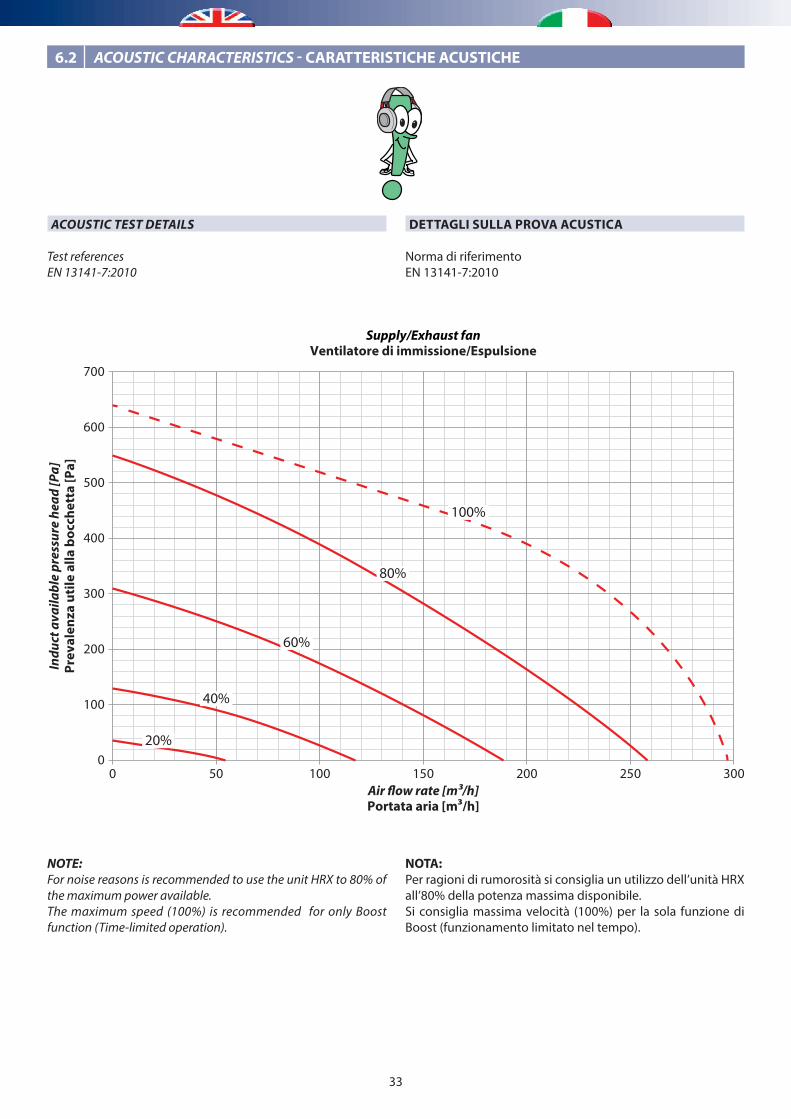
NOTA:Per ragioni di rumorosità si consiglia un utilizzo dell’unità HRX all’80% della potenza massima disponibile.Si consiglia massima velocità (100%) per la sola funzione di Boost (funzionamento limitato nel tempo).
NOTE:For noise reasons is recommended to use the unit HRX to 80% of the maximum power available. The maximum speed (100%) is recommended for only Boost function (Time-limited operation).
DETTAGLI SULLA PROVA ACUSTICA
Norma di riferimentoEN 13141-7:2010
ACOUSTIC TEST DETAILS
Test referencesEN 13141-7:2010
34
Note:* Valori di fondo che rappresentano i limiti superiori al livello di potenza sonora della fonte di rumore in fase di test.** Livello stimato di pressione sonora con curva di pesatura A a 3 m e assumendo una propagazione sferica a campo aperto.Valore massimo tipico presunto tra la Curva 40% e la Curva 60%, stimato a 35dB(A) @3m.
Note:* Valori di fondo che rappresentano i limiti superiori al livello di potenza sonora della fonte di rumore in fase di test.
Note:* Valori di fondo che rappresentano i limiti superiori al livello di potenza sonora della fonte di rumore in fase di test.
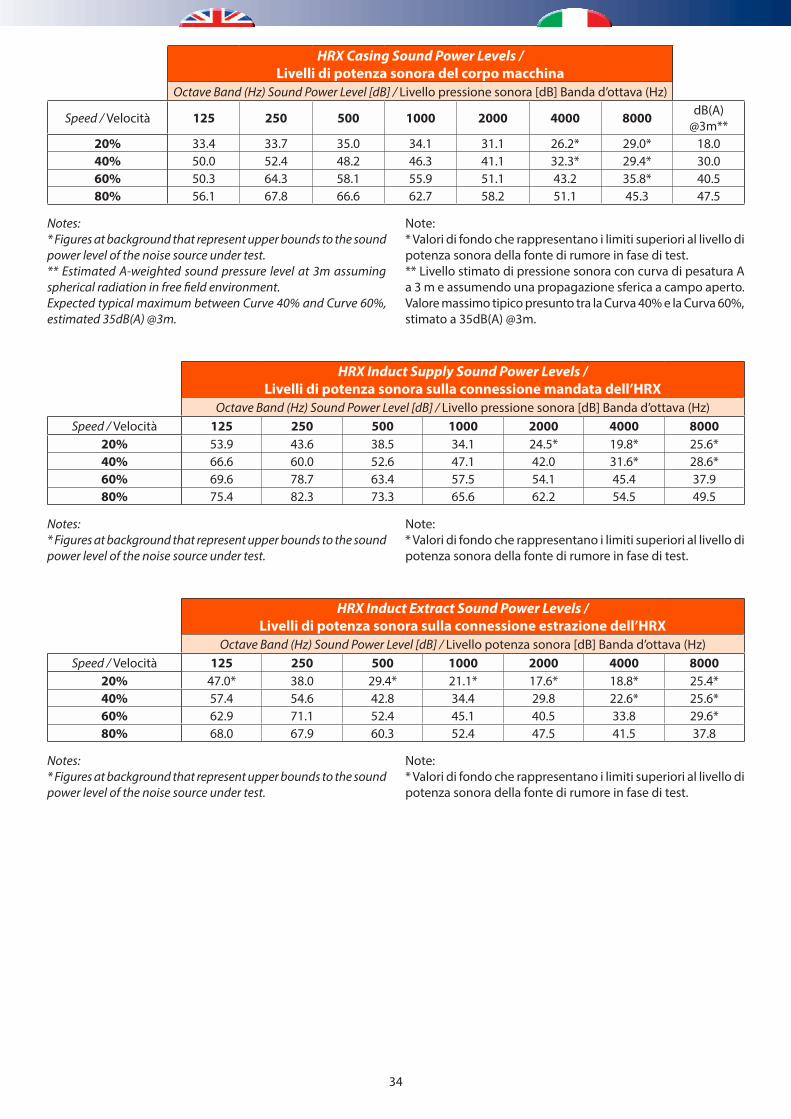
Notes:* Figures at background that represent upper bounds to the sound power level of the noise source under test.** Estimated A-weighted sound pressure level at 3m assuming spherical radiation in free field environment.Expected typical maximum between Curve 40% and Curve 60%, estimated 35dB(A) @3m.
Notes:* Figures at background that represent upper bounds to the sound power level of the noise source under test.
Notes:* Figures at background that represent upper bounds to the sound power level of the noise source under test.
HRX Casing Sound Power Levels /Livelli di potenza sonora del corpo macchina
Octave Band (Hz) Sound Power Level [dB] / Livello pressione sonora [dB] Banda d’ottava (Hz)
Speed / Velocità 125 250 500 1000 2000 4000 8000 dB(A)@3m**
20% 33.4 33.7 35.0 34.1 31.1 26.2* 29.0* 18.040% 50.0 52.4 48.2 46.3 41.1 32.3* 29.4* 30.060% 50.3 64.3 58.1 55.9 51.1 43.2 35.8* 40.580% 56.1 67.8 66.6 62.7 58.2 51.1 45.3 47.5
HRX Induct Supply Sound Power Levels / Livelli di potenza sonora sulla connessione mandata dell’HRX
Octave Band (Hz) Sound Power Level [dB] / Livello pressione sonora [dB] Banda d’ottava (Hz)Speed / Velocità 125 250 500 1000 2000 4000 8000
20% 53.9 43.6 38.5 34.1 24.5* 19.8* 25.6*40% 66.6 60.0 52.6 47.1 42.0 31.6* 28.6*60% 69.6 78.7 63.4 57.5 54.1 45.4 37.980% 75.4 82.3 73.3 65.6 62.2 54.5 49.5
HRX Induct Extract Sound Power Levels / Livelli di potenza sonora sulla connessione estrazione dell’HRX
Octave Band (Hz) Sound Power Level [dB] / Livello potenza sonora [dB] Banda d’ottava (Hz)Speed / Velocità 125 250 500 1000 2000 4000 8000
20% 47.0* 38.0 29.4* 21.1* 17.6* 18.8* 25.4*40% 57.4 54.6 42.8 34.4 29.8 22.6* 25.6*60% 62.9 71.1 52.4 45.1 40.5 33.8 29.6*80% 68.0 67.9 60.3 52.4 47.5 41.5 37.8
35
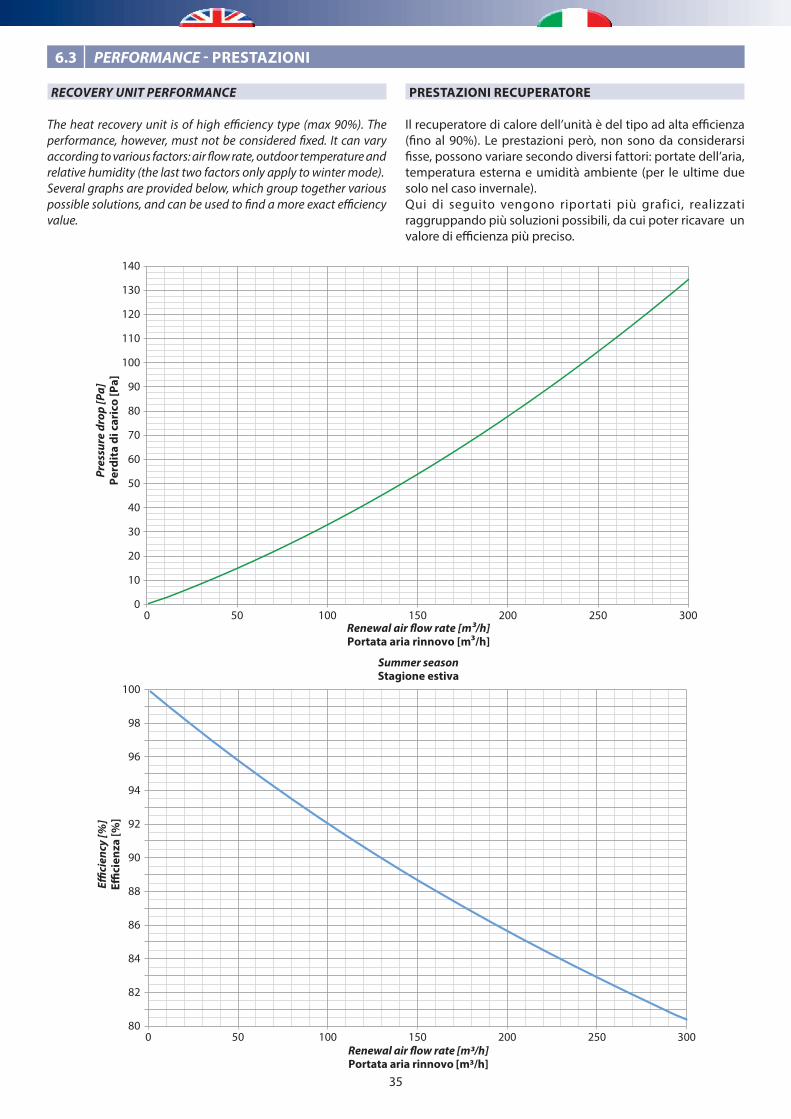
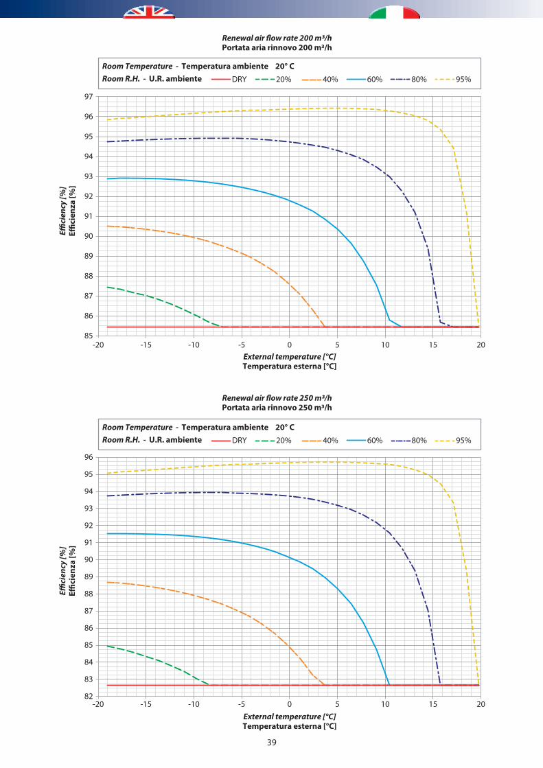
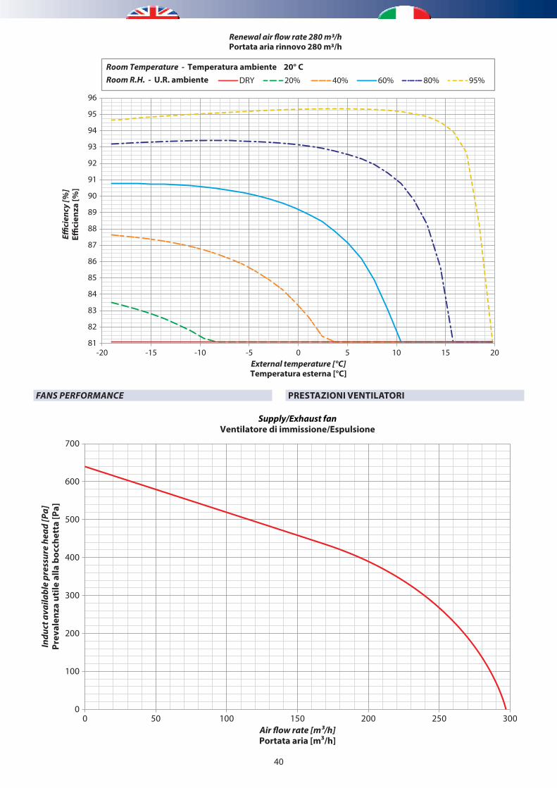
PRESTAZIONI RECUPERATORE
Il recuperatore di calore dell’unità è del tipo ad alta efficienza (fino al 90%). Le prestazioni però, non sono da considerarsi fisse, possono variare secondo diversi fattori: portate dell’aria, temperatura esterna e umidità ambiente (per le ultime due solo nel caso invernale).Qui di seguito vengono riportati più grafici, realizzati raggruppando più soluzioni possibili, da cui poter ricavare un valore di efficienza più preciso.
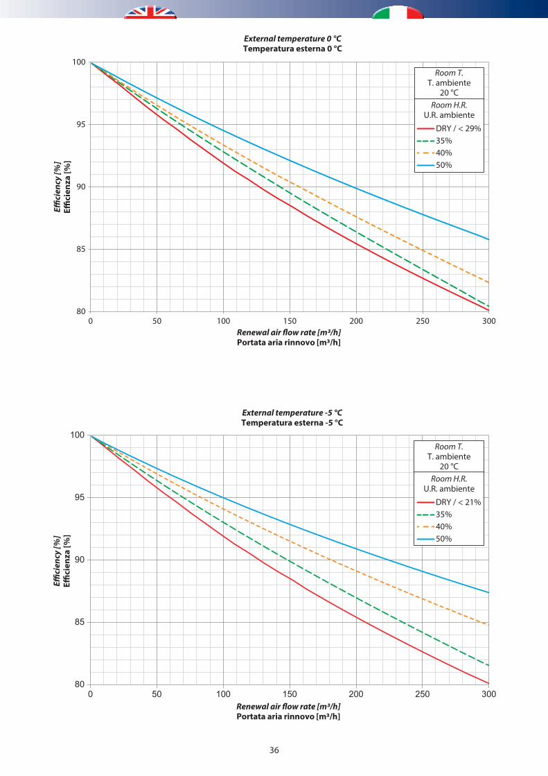
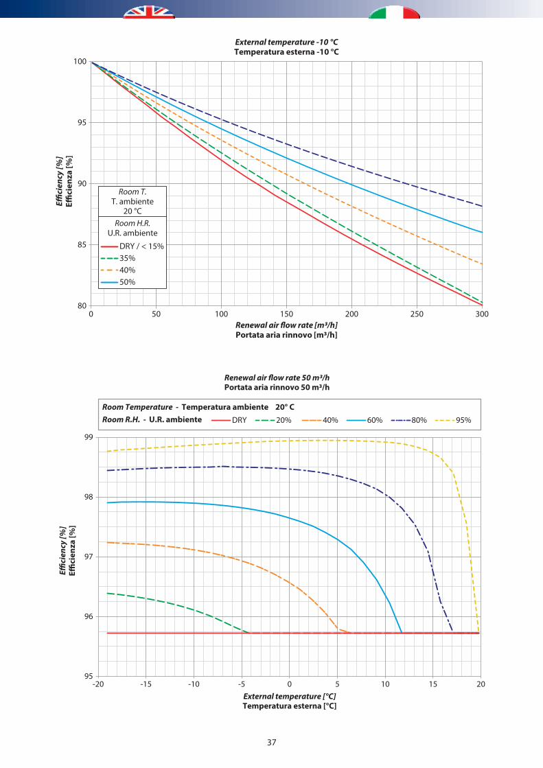
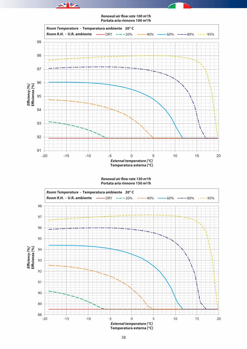
RECOVERY UNIT PERFORMANCE
The heat recovery unit is of high efficiency type (max 90%). The performance, however, must not be considered fixed. It can vary according to various factors: air flow rate, outdoor temperature and relative humidity (the last two factors only apply to winter mode).Several graphs are provided below, which group together various possible solutions, and can be used to find a more exact efficiency value.
0
10
20
30
40
50
60
70
80
90
100
110
120
130
140
0 50 100 150 200 250 300
Perd
ita
di c
aric
o [P
a]Pr
essu
re d
rop
[Pa]
Portata aria rinnovo [m3/h]Renewal air �ow rate [m3/h]
80
82
84
86
88
90
92
94
96
98
100
0 50 100 150 200 250 300
E�ci
enza
[%]
Renewal air �ow rate [m3/h]Portata aria rinnovo [m3/h]
Stagione estivaSummer season
Eci
ency
[%]
6.3 PERFORMANCE - PRESTAZIONI
36
80
85
90
95
100
0 50 100 150 200 250 300
E�ci
enza
[%]
E�ci
ency
[%]
Renewal air �ow rate [m3/h]Portata aria rinnovo [m3/h]
Temperatura esterna 0 °CExternal temperature 0 °C
DRY / < 29%
U.R. ambienteRoom H.R.
T. ambienteRoom T.
35%
20 °C
40%50%
80
85
90
95
100
0 50 100 150 200 250 300
E�ci
enza
[%]
E�ci
ency
[%]
Renewal air �ow rate [m3/h]Portata aria rinnovo [m3/h]
Temperatura esterna -5 °CExternal temperature -5 °C
DRY / < 21%
U.R. ambienteRoom H.R.
T. ambienteRoom T.
35%
20 °C
40%50%
37
80
85
90
95
100
0 50 100 150 200 250 300
E�ci
enza
[%]
E�ci
ency
[%]
Renewal air �ow rate [m3/h]Portata aria rinnovo [m3/h]
Temperatura esterna -10 °CExternal temperature -10 °C
DRY / < 15%
U.R. ambienteRoom H.R.
T. ambienteRoom T.
35%
20 °C
40%50%
95
96
97
98
99
-20 -15 -10 -5 0 5 10 15 20
E�ci
enza
[%]
E�ci
ency
[%]
Renewal air �ow rate 50 m3/hPortata aria rinnovo 50 m3/h
Temperatura esterna [°C]External temperature [°C]
Room R.H. - U.R. ambienteRoom Temperature - Temperatura ambiente 20° C
20%DRY 40% 60% 80% 95%
38
91
92
93
94
95
96
97
98
99
-20 -15 -10 -5 0 5 10 15 20
E�ci
enza
[%]
E�ci
ency
[%]
Renewal air �ow rate 100 m3/hPortata aria rinnovo 100 m3/h
Temperatura esterna [°C]External temperature [°C]
Room R.H. - U.R. ambienteRoom Temperature - Temperatura ambiente 20° C
20%DRY 40% 60% 80% 95%
88
89
90
91
92
93
94
95
96
97
98
-20 -15 -10 -5 0 5 10 15 20
E�ci
enza
[%]
E�ci
ency
[%]
Renewal air �ow rate 150 m3/hPortata aria rinnovo 150 m3/h
Temperatura esterna [°C]External temperature [°C]
Room R.H. - U.R. ambienteRoom Temperature - Temperatura ambiente 20° C
20%DRY 40% 60% 80% 95%
39
85
86
87
88
89
90
91
92
93
94
95
96
97
-20 -15 -10 -5 0 5 10 15 20
E�ci
enza
[%]
E�ci
ency
[%]
Renewal air �ow rate 200 m3/hPortata aria rinnovo 200 m3/h
Temperatura esterna [°C]External temperature [°C]
Room R.H. - U.R. ambienteRoom Temperature - Temperatura ambiente 20° C
20%DRY 40% 60% 80% 95%
82
83
84
85
86
87
88
89
90
91
92
93
94
95
96
-20 -15 -10 -5 0 5 10 15 20
E�ci
enza
[%]
E�ci
ency
[%]
Renewal air �ow rate 250 m3/hPortata aria rinnovo 250 m3/h
Temperatura esterna [°C]External temperature [°C]
Room R.H. - U.R. ambienteRoom Temperature - Temperatura ambiente 20° C
20%DRY 40% 60% 80% 95%
40
0
100
200
300
400
500
600
700
0 50 100 150 200 250 300
Portata aria [m3/h]Air �ow rate [m3/h]
Ventilatore di immissione/EspulsioneSupply/Exhaust fan
Prev
alen
za u
tile
alla
boc
chet
ta [P
a]In
duct
ava
ilabl
e pr
essu
re h
ead
[Pa]
PRESTAZIONI VENTILATORIFANS PERFORMANCE
81
82
83
84
85
86
87
88
89
90
91
92
93
94
95
96
-20 -15 -10 -5 0 5 10 15 20
E�ci
enza
[%]
E�ci
ency
[%]
Renewal air �ow rate 280 m3/hPortata aria rinnovo 280 m3/h
Temperatura esterna [°C]External temperature [°C]
Room R.H. - U.R. ambienteRoom Temperature - Temperatura ambiente 20° C
20%DRY 40% 60% 80% 95%
41
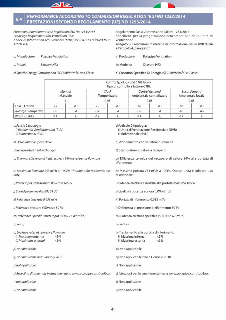
6.4 PERFORMANCE ACCORDING TO COMMISSION REGULATION (EU) NO 1253/2014PRESTAZIONI SECONDO REGOLAMENTO (UE) NO 1253/2014
European Union Commission Regulation (EU) No 1253/2014Ecodesign Requirements for Ventilation UnitsAnnex IV Information requirements [fiche] for RVUs as referred to in Article 4(1)
a) Manufacturer: Polypipe Ventilation
b) Model: Silavent HRX
c) Specific Energy Consumption (SEC) kWh/(m²a) and Class:
d)Article 2 typology:I) Residential Ventilation Unit (RVU)II) Bidirectional (BVU)
e) Drive Variable speed drive
f) Recuperative heat exchanger
g) Thermal efficiency of heat recovery 84% at reference flow rate
h) Maximum flow rate 253 m³/h at 100Pa. This unit is for residential use only.
i) Power input at maximum flow rate 105 W
j) Sound power level (LWA) 61 dB
k) Reference flow rate 0.053 m³/s
l) Reference pressure difference 50 Pa
m) Reference Specific Power Input (SPI) 0.27 W/(m³/h)
n) see c)
o) Leakage rates at reference flow rateI) Maximum internal <5% II) Maximum external <5%
p) not applicable
q) not applicable until January 2018
r) not applicable
s) Recycling disassembly instruction - go to www.polypipe.com/toolbox
t) not applicable
u) not applicable
Control typology and CTRL factorTipo di controllo e fattore CTRL
ManualManuale
ClockTemporizzato
Central demandAmbientale centralizzato
Local demandAmbientale locale
1 0.95 0.85 0.65
Cold - Freddo -77 A+ -79 A+ -82 A+ -86 A+
Average - Temperato -35 A -37 A -39 A -43 A+
Warm - Caldo -11 E -12 E -14 E -17 E
Regolamento Della Commissione (UE) N. 1253/2014Specifiche per la progettazione ecocompatibile delle unità di ventilazioneAllegato IV Prescrizioni in materia di informazione per le UVR di cui all’articolo 4, paragrafo 1
a) Produttore: Polypipe Ventilation
b) Modello: Silavent HRX
c) Consumo Specifico Di Energia (SEC) kWh/(m²a) e Classe:
d)Articolo 2 tipologia:I) Unità di Ventilazione Residenziale (UVR)II) Bidirezionale (BVU)
e) Azionamento con variatore di velocità
f ) Scambiatore di calore a recupero
g) Efficienza termica del recupero di calore 84% alla portata di riferimento
h) Massima portata 253 m³/h a 100Pa. Questa unità è solo per uso residenziale.
i) Potenza elettrica assorbita alla portata massima 105 W
j) Livello di potenza sonora (LWA) 61 dB
k) Portata di riferimento 0.053 m³/s
l) Differenza di pressione di riferimento 50 Pa
m) Potenza elettrica specifica (SPI) 0.27 W/(m³/h)
n) vedi c)
o) Trafilamento alla portata di riferimentoI) Massima interna <5% II) Massima esterna <5%
p) Non applicabile
q) Non applicabile fino a Gennaio 2018
r) Non applicabile
s) Istruzioni per lo smaltimento -vai a www.polypipe.com/toolbox
t) Non applicabile
u) Non applicabile
42
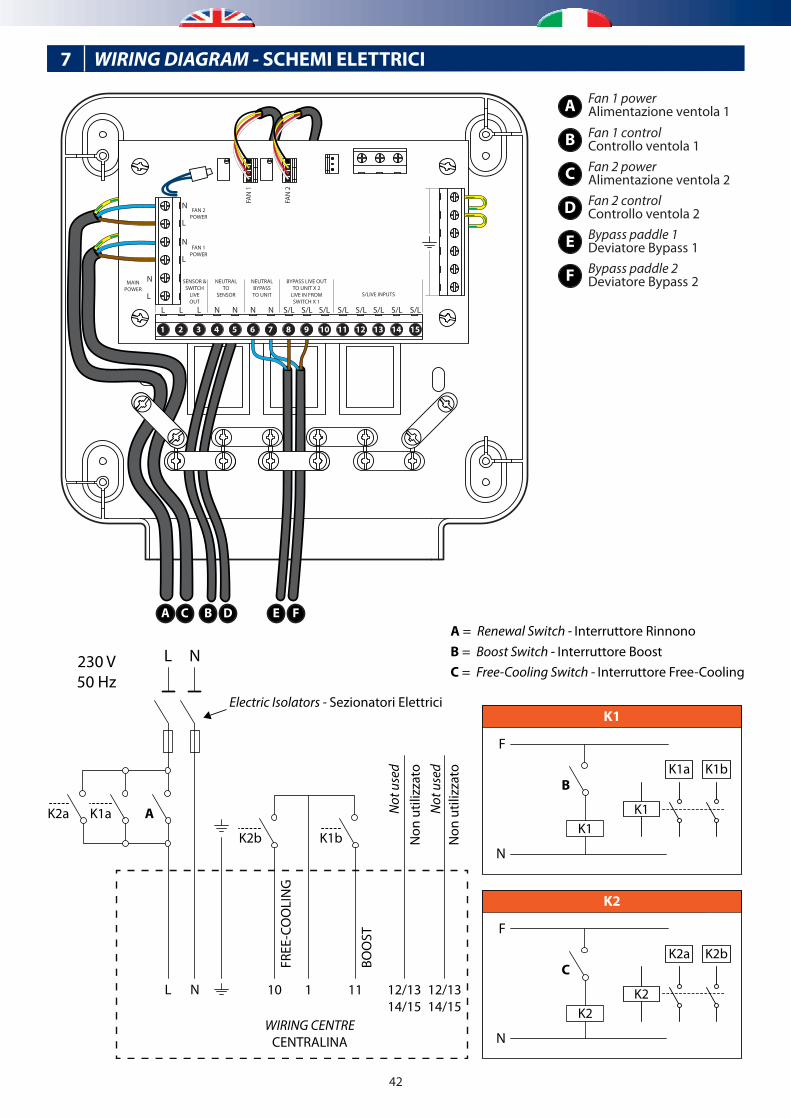
7 WIRING DIAGRAM - SCHEMI ELETTRICI
A C B D E F
1 15141312111098765432
K1
F
N
Electric Isolators - Sezionatori Elettrici
BOO
ST
K1b Non
util
izza
toN
ot u
sed
Non
util
izza
toN
ot u
sed
K1a A
B
A = Renewal Switch - Interruttore RinnonoB = Boost Switch - Interruttore BoostC = Free-Cooling Switch - Interruttore Free-Cooling
K2a
L
L
N
N
FREE
-CO
OLI
NG
K2b
11 12/1314/15
12/1314/15
110
WIRING CENTRECENTRALINA
K1K1
K1bK1a
K2
F
N
C
K2K2
K2bK2a
A
B
C
D
Fan 1 powerAlimentazione ventola 1Fan 1 controlControllo ventola 1Fan 2 powerAlimentazione ventola 2Fan 2 controlControllo ventola 2
E
F
Bypass paddle 1Deviatore Bypass 1Bypass paddle 2 Deviatore Bypass 2
N
L
MAINPOWER
FAN 2POWER
FAN 1POWER
S/LIVE INPUTS
BYPASS LIVE OUTTO UNIT X 2
LIVE IN FROMSWITCH X 1
NEUTRALBYPASSTO UNIT
NEUTRALTO
SENSOR
SENSOR &SWITCH
LIVEOUT
FAN
1
FAN
2
N
L
L L L N N N N S/L S/L S/L S/L S/L S/L S/L S/L
N
L
230 V50 Hz

Air Handling UnitsUnità Trattamento Aria
SILAVENT HRX
TECHNICAL/INSTALLATION MANUALMANUALE TECNICO/INSTALLAZIONE
Mechanical ventilation with heat recovery applianceVentilazione meccanica con sistema di recupero di calore
9100
328.
02 -
03/2
016