air-insulated medium-voltage switchgear nxair, up to 24 kv · 4 air-insulated medium-voltage...
TRANSCRIPT
Totally Integrated Power – NXAIR
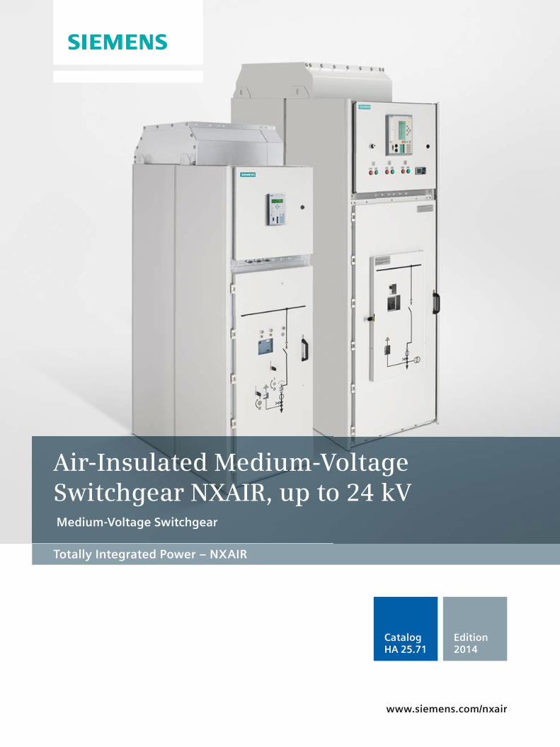
Air-Insulated Medium-Voltage Switchgear NXAIR, up to 24 kV Medium-Voltage Switchgear
www.siemens.com/nxair
Edition2014
CatalogHA 25.71
2 Air-Insulated Medium-Voltage Switchgear NXAIR, up to 24 kV · Siemens HA 25.71 · 2014
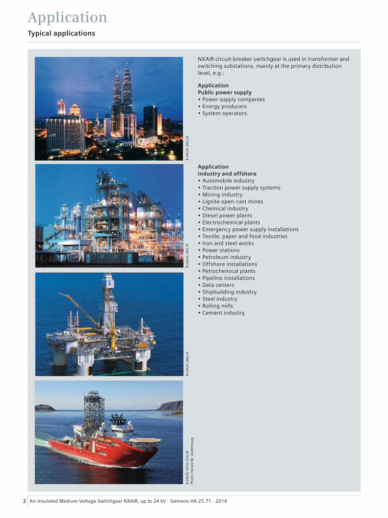
NXAIR circuit-breaker switchgear is used in transformer and switching substations, mainly at the primary distribution level, e.g.:
ApplicationPublic power supply• Power supply companies• Energy producers• System operators.
ApplicationIndustry and offshore• Automobile industry• Traction power supply systems• Mining industry• Lignite open-cast mines• Chemical industry• Diesel power plants• Electrochemical plants• Emergency power supply installations• Textile, paper and food industries• Iron and steel works• Power stations• Petroleum industry• Offshore installations• Petrochemical plants• Pipeline installations• Data centers• Shipbuilding industry• Steel industry• Rolling mills• Cement industry.
R-H
A3
5-0
510
-016
.tif
Pho
to: H
aral
d M
. Val
der
hau
gR-
HA
25
-36
6.t
ifR-
HA
25
-36
3.t
ifR-
HA
25
-36
2.t
if
ApplicationTypical applications
3Air-Insulated Medium-Voltage Switchgear NXAIR, up to 24 kV · Siemens HA 25.71 · 2014
Contents
Application Page
Typical applications 2
Customer benefi t
Ensures peace of mind 4
Saves lives 5
Increases productivity 6
Saves money 7
Preserves the environment 8
Design
Classifi cation 9
Basic panel design, operation 10 and 11
Compartments 12
Components
Vacuum circuit-breaker 13
Vacuum contactor 14
Current transformers 15
Voltage transformers 16
Low-voltage compartment 17
Technical data 17.5 kV
Electrical data 18 Product range, switchgear panels 19 and 20
Dimensions 21
Room planning 22
Transport and packing 23
Technical data 24 kV
Electrical data 24 Product range, switchgear panels 25 and 26
Dimensions 27
Room planning 28
Transport and packing 29
Standards
Standards, specifi cations, guidelines 30 and 31
Air-Insulated Medium-Voltage Switchgear NXAIR, up to 24 kVMedium-Voltage Switchgear
Catalog HA 25.71 · 2014
Invalid: Catalog HA 25.71 · 2013
www.siemens.com/nxair
The products and systems described in this catalog are manufactured and sold according to a certifi ed management system (acc. to ISO 9001, ISO 14001 and BS OHSAS 18001).
4 Air-Insulated Medium-Voltage Switchgear NXAIR, up to 24 kV · Siemens HA 25.71 · 2014
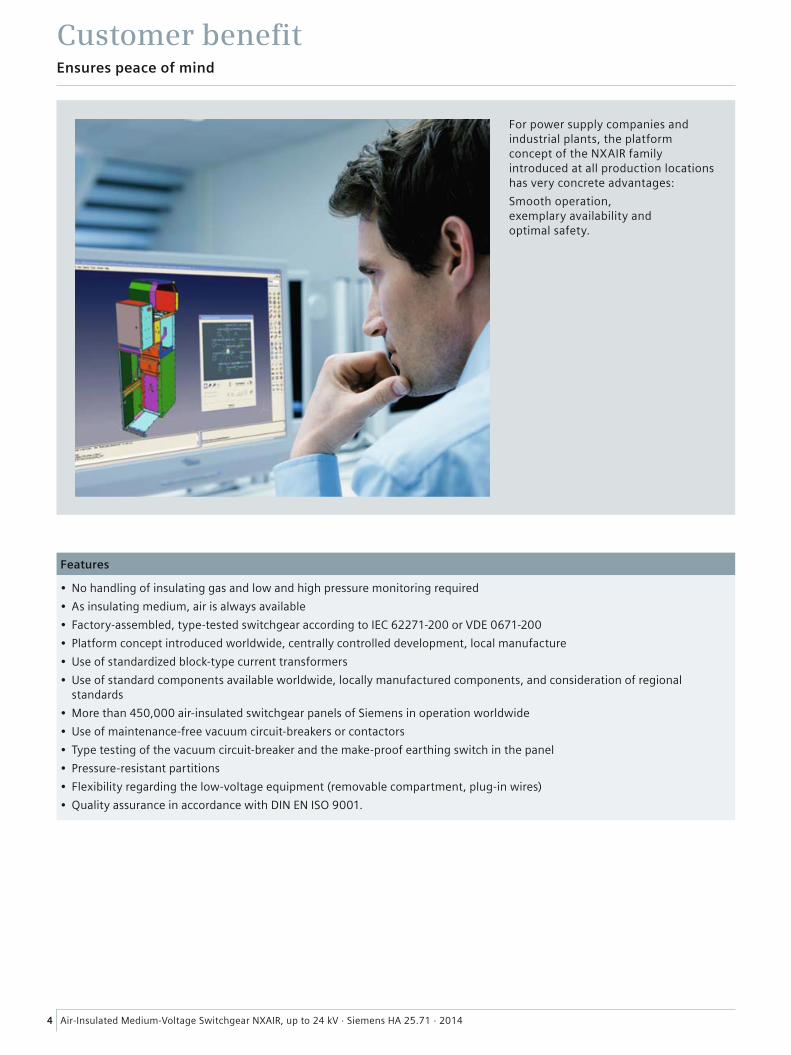
Customer benefi tEnsures peace of mind
Features
• No handling of insulating gas and low and high pressure monitoring required
• As insulating medium, air is always available
• Factory-assembled, type-tested switchgear according to IEC 62271-200 or VDE 0671-200
• Platform concept introduced worldwide, centrally controlled development, local manufacture
• Use of standardized block-type current transformers
• Use of standard components available worldwide, locally manufactured components, and consideration of regional standards
• More than 450,000 air-insulated switchgear panels of Siemens in operation worldwide
• Use of maintenance-free vacuum circuit-breakers or contactors
• Type testing of the vacuum circuit-breaker and the make-proof earthing switch in the panel
• Pressure-resistant partitions
• Flexibility regarding the low-voltage equipment (removable compartment, plug-in wires)
• Quality assurance in accordance with DIN EN ISO 9001.
For power supply companies and industrial plants, the platform concept of the NXAIR family introduced at all production locations has very concrete advantages:
Smooth operation, exemplary availability and optimal safety.
5Air-Insulated Medium-Voltage Switchgear NXAIR, up to 24 kV · Siemens HA 25.71 · 2014
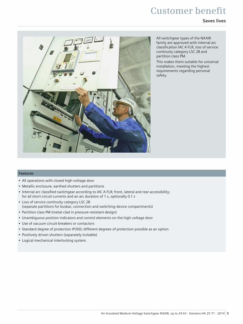
Customer benefi t Saves lives
Features
• All operations with closed high-voltage door
• Metallic enclosure, earthed shutters and partitions
• Internal arc classifi ed switchgear according to IAC A FLR; front, lateral and rear accessibility; for all short-circuit currents and an arc duration of 1 s, optionally 0.1 s
• Loss of service continuity category LSC 2B (separate partitions for busbar, connection and switching-device compartments)
• Partition class PM (metal-clad in pressure-resistant design)
• Unambiguous position indicators and control elements on the high-voltage door
• Use of vacuum circuit-breakers or contactors
• Standard degree of protection IP3XD; different degrees of protection possible as an option
• Positively driven shutters (separately lockable)
• Logical mechanical interlocking system.
All switchgear types of the NXAIR family are approved with internal arc classifi cation IAC A FLR, loss of service continuity category LSC 2B and partition class PM.
This makes them suitable for universal installation, meeting the highest requirements regarding personal safety.

6 Air-Insulated Medium-Voltage Switchgear NXAIR, up to 24 kV · Siemens HA 25.71 · 2014
Customer benefi t Increases productivity
Features
• Loss of service continuity category LSC 2B (separate partitions for busbar, connection and switching-device compartments)
• Partition class PM
• Maximum degree of protection IP51 possible
• Positively driven shutters
• Use of standardized block-type current transformers
• Cable testing without isolating the busbar
• Functions such as establishment of the isolating distance, as well as feeder and busbar earthing, can be completely controlled from remote
• Confi nement of an internal arc to the respective compartment up to 31.5 kA
• Use of maintenance-free vacuum circuit-breakers or contactors
• Control cables in metallic wiring ducts
• Easy access to all panel components.
Properties such as modular design, types tests of the circuit-breaker in the switchgear, confi nement of an internal arc to the respective compartment, and thus maximum operational reliability, contribute to optimum operation and a remarkable increase of productivity.
7Air-Insulated Medium-Voltage Switchgear NXAIR, up to 24 kV · Siemens HA 25.71 · 2014
Customer benefi t Saves money
Features
• Use of maintenance-free vacuum circuit-breakers or contactors
• Maintenance-free switchgear within up to 10 years
• Interruption of operation reduced to a minimum by logical mechanical interlocking system
• Minimized space requirements (reduced building investments) due to compact design and fl exible cable connection options and /or fl exible pressure relief duct systems.
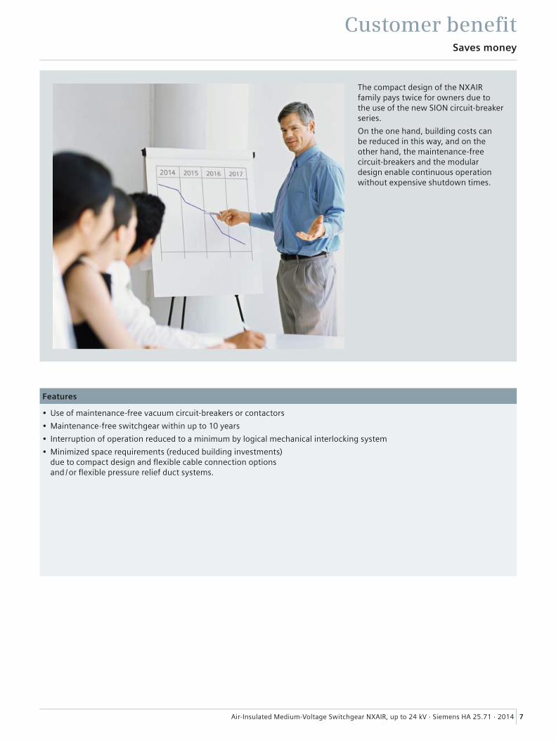
The compact design of the NXAIR family pays twice for owners due to the use of the new SION circuit-breaker series.
On the one hand, building costs can be reduced in this way, and on the other hand, the maintenance-free circuit-breakers and the modular design enable continuous operation without expensive shutdown times.

8 Air-Insulated Medium-Voltage Switchgear NXAIR, up to 24 kV · Siemens HA 25.71 · 2014
Customer benefi t Preserves the environment
Features
• As insulating medium, air is absolutely neutral to the environment
• Local production presence in all regions, minimized energy consumption (CO2) regarding transport
• Service life of more than 30 years optimizes the energy balance additionally
• The materials used are fully recyclable without special knowledge
• Easy disposal.
Air used as insulating medium, local production locations with short transportation ways and times, as well as a service life of more than 30 years, optimize the total energy balance.
9Air-Insulated Medium-Voltage Switchgear NXAIR, up to 24 kV · Siemens HA 25.71 · 2014
Design
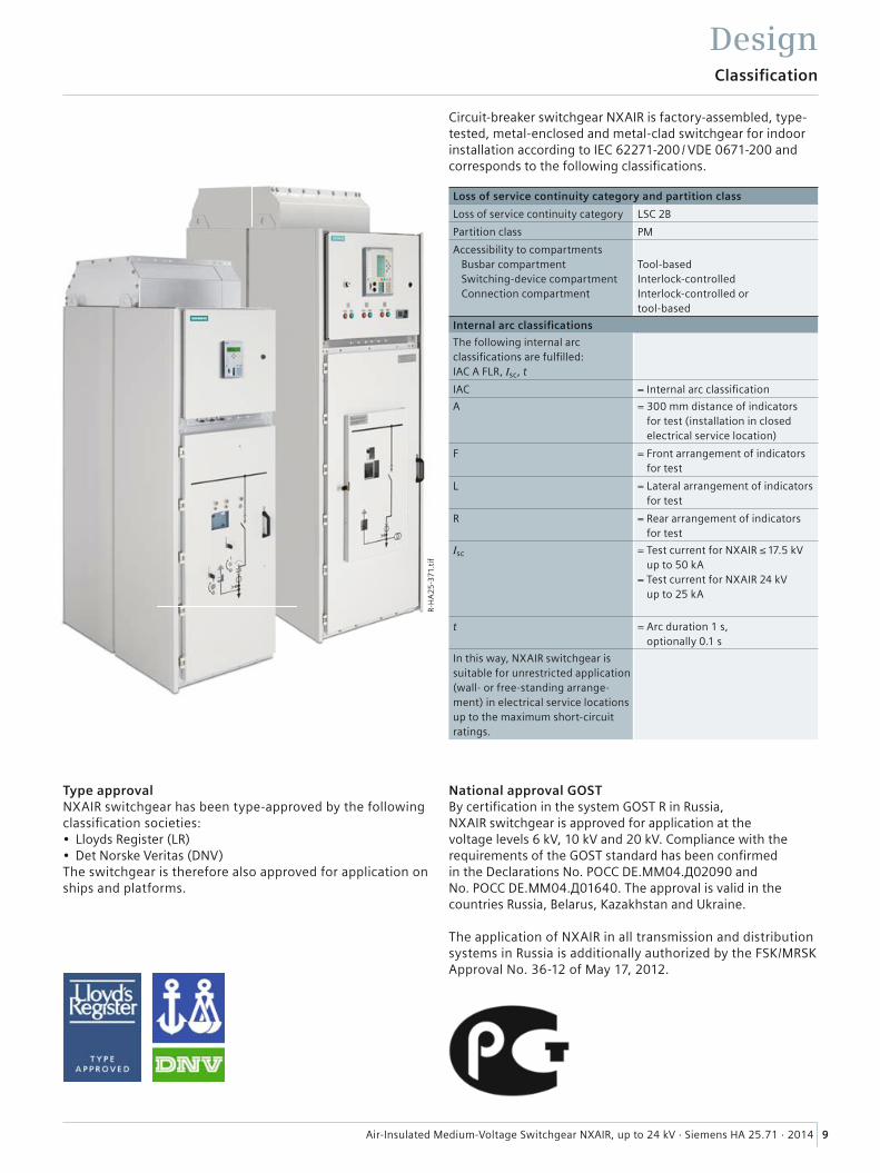
Circuit-breaker switchgear NXAIR is factory-assembled, type-tested, metal-enclosed and metal-clad switchgear for indoor installation according to IEC 62271-200 / VDE 0671-200 and corresponds to the following classifi cations.
Loss of service continuity category and partition class
Loss of service continuity category LSC 2B
Partition class PM
Accessibility to compartments Busbar compartment Switching-device compartment Connection compartment
Tool-basedInterlock-controlledInterlock-controlled or tool-based
Internal arc classifi cations
The following internal arc classifi cations are fulfi lled:IAC A FLR, Isc, t
IAC = Internal arc classifi cation
A = 300 mm distance of indicators for test (installation in closed electrical service location)
F = Front arrangement of indicators for test
L = Lateral arrangement of indicators for test
R = Rear arrangement of indicators for test
Isc = Test current for NXAIR ≤ 17.5 kVup to 50 kA
= Test current for NXAIR 24 kV up to 25 kA
t = Arc duration 1 s, optionally 0.1 s
In this way, NXAIR switchgear is suitable for unrestricted application (wall- or free-standing arrange-ment) in electrical service locations up to the maximum short-circuit ratings.
Classifi cation
Type approvalNXAIR switchgear has been type-approved by the following classifi cation societies:• Lloyds Register (LR)• Det Norske Veritas (DNV) The switchgear is therefore also approved for application on ships and platforms.
National approval GOSTBy certifi cation in the system GOST R in Russia, NXAIR switchgear is approved for application at the voltage levels 6 kV, 10 kV and 20 kV. Compliance with the requirements of the GOST standard has been confi rmed in the Declarations No. POCC DE.MM04.Д02090 and No. POCC DE.MM04.Д01640. The approval is valid in the countries Russia, Belarus, Kazakhstan and Ukraine.
The application of NXAIR in all transmission and distribution systems in Russia is additionally authorized by the FSK/MRSK Approval No. 36-12 of May 17, 2012.
R-H
A2
5-3
71.t
if

HA
25
-26
11
l eps
13
18
14
15
16
17
19
23
21
24
22
20
1
2
3
4
6
11
7
9
5
8
E
D
A
C
B
10
12
25
10 Air-Insulated Medium-Voltage Switchgear NXAIR, up to 24 kV · Siemens HA 25.71 · 2014
Basic panel design, operation
Design
Operation at the panel
Features• Integrated mimic diagram• Recognition of the respec-
tive switch positions, circuit-breaker CLOSED / OPEN, earthing switch CLOSED /OPEN, on the integrated mimic diagram
• Unambiguous assignment of actuating openings and control elements to the corresponding position indicators
• All switching operations always with high-voltage door closed
• Ergonomically favorable height for all control and indicator elements
• Option: Verifi cation of safe isolation from supply for feeder or busbar by means of the capacitive voltage detecting system with panel front closed.
Interlocks• Interlocking conditions
specifi ed according to IEC 62271-200 /VDE 0671-200 are fulfi lled
• Feeder earthing switch can only be operated with switching device in discon-nected position
• Switching device can only be racked on the movablepart with the associated switching device OPEN position and with earthing switch OPEN
• Switching device can only be operated in interlocked disconnected or service position.
Beyond the specifi cationsof the standards• Coding prevents insertion
of switching devices with a lower rated normal current into panels with a higher rated normal current
• Interlocking between the high-voltage door and the position of the withdraw-able part
• Option: Electromagnetic interlocks, mechanical key interlocking systems, padlocks.
1 Door to low-voltage compartment
2 Protection device
3 Option: Capacitive voltage detecting system for feeder and busbar
4 High-voltage door
5 Mimic diagram
6 “CLOSE-OPEN“ actuating openings for the circuit-breaker, opening for spring charging
7 Inspection window to recognize the “CLOSED-OPEN“ indicator of the circuit-breaker, “closing spring charged“ indicator, operations counter
8 Handle for opening the high-voltage door
9 Actuating opening for racking the switching device
10 Mechanical position indicator for feeder earthing switch
11 Actuating opening for feeder earthing switch, manual or optionally motor operation
12 Mechanical position indicator for withdrawable part
13 Pressure relief duct, if required with top-mounted arc absorber
14 Busbars
15 Bushing-type insulator
16 Block-type current transformer
17 Voltage transformer
18 Cable connection for max. 6 cables per phase
19 Make-proof earthing switch
20 Low-voltage connection, plug-in type
21 Operating and interlocking unit for circuit-breaker
22 Vacuum interrupters
23 Contact system
24 Withdrawable part for racking the switching device and for earthing, manual or optionally motor operation
25 Option: Withdrawable voltage transformers
Basic panel design (example)
A Switching-device compartment
B Busbar compartment
C Connection compartment
D Withdrawable circuit-breaker
E Low-voltage compartment
11Air-Insulated Medium-Voltage Switchgear NXAIR, up to 24 kV · Siemens HA 25.71 · 2014
Design Basic panel design, operation
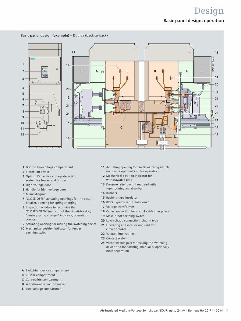
Basic panel design (example) – Duplex (back-to-back)
1 Door to low-voltage compartment
2 Protection device
3 Option: Capacitive voltage detecting system for feeder and busbar
4 High-voltage door
5 Handle for high-voltage door
6 Mimic diagram
7 “CLOSE-OPEN“ actuating openings for the circuit-breaker, opening for spring charging
8 Inspection window to recognize the “CLOSED-OPEN“ indicator of the circuit-breaker, “closing spring charged“ indicator, operations counter
9 Actuating opening for racking the switching device
10 Mechanical position indicator for feeder earthing switch
11 Actuating opening for feeder earthing switch, manual or optionally motor operation
12 Mechanical position indicator for withdrawable part
13 Pressure relief duct, if required with top-mounted arc absorber
14 Busbars
15 Bushing-type insulator
16 Block-type current transformer
17 Voltage transformer
18 Cable connection for max. 4 cables per phase
19 Make-proof earthing switch
20 Low-voltage connection, plug-in type
21 Operating and interlocking unit for circuit-breaker
22 Vacuum interrupters
23 Contact system
24 Withdrawable part for racking the switching device and for earthing, manual or optionally motor operation
A Switching-device compartment
B Busbar compartment
C Connection compartment
D Withdrawable circuit-breaker
E Low-voltage compartment
HA
25
-27
10
a ep
s
1
2
3
4
5
7
11
13
19
14
15
17
20
18
23
21
24
22
8
9
6
A
C
B E
D
12
10
13
15
14
C
D
A BE
21
AB
16
24
20
12 Air-Insulated Medium-Voltage Switchgear NXAIR, up to 24 kV · Siemens HA 25.71 · 2014
Compartments
Design
Switching-device compartment• Enclosure made of sendzimir-galvanized sheet steel• Pressure relief upwards• Panel front powder-coated with epoxy resin• Standard color RAL 7035• Separate shutter mechanism for opening and closing the – Busbar compartment– Connection compartment• High-voltage door pressure-resistant in the event of
internal arcs in the panel• Pressure-resistant partitions to connection and
busbar compartments• Lateral metallic wiring duct for laying the control cables• Low-voltage plug connector for connection of control
cables between primary part and secondary part• Switching-device compartment for the different panel
versions with withdrawable devices:– Vacuum circuit-breaker 1)
– Vacuum contactor– Disconnector link– Metering unit• Endurance classes for:– Circuit-breaker: E2, M2, C2– Switch: M1, C2– Isolating distance (withdrawable part): M0
manually or partly motor-operated for withdrawable circuit-breaker and disconnector link
– Vacuum contactor 250,000, 500,000 or 1,000,000 × IN• Transformer panel for auxiliaries service with switch-
disconnector/fuse combination, fi xed-mounted (LSC 2A); endurance class for switch-disconnector E1, M0.
Busbar compartment• Enclosure made of sendzimir-galvanized sheet steel• Pressure relief upwards• Option: Transverse partition from panel to panel for NXAIR
Standard: Transverse partition from panel to panel for NXAIR 50 kA
• Busbars made of fl at copper, bolted from panel to panel– Option: Insulated
• Pressure-resistant partitions to connection and switching-device compartment, pressure-resistant rear wall
• Shutters can be opened and locked separately• Bushing-type insulators for supporting the busbars and for
accommodating the upper fi xed contacts for the switching device
• Option: Coupling electrode for capacitive voltage detecting system.
Additional compartments (option) for busbar components,see also product range• Top-mounted compartment over the busbar compartment,
within the pressure relief duct• Separate pressure relief of the additional compartment
via pressure relief fl aps• Options: Possibility of installing the following components
(but not for panels with natural and forced ventilation, see also product range)
– Voltage transformers– Make-proof earthing switch (endurance class: M0, E1),
manual or optionally motor operation.
Connection compartment• Enclosure made of sendzimir-galvanized sheet steel• Pressure relief upwards through rear pressure relief duct• Pressure-resistant partitions to switching-device and
busbar compartments• Shutters can be opened and locked separately• Earthing busbar• Option: Installation of bushing-type insulators or
block-type current transformers• Option: Coupling electrode for capacitive voltage
detecting system• Pressure-resistant fl oor cover• Connection from front/bottom, or from rear/bottom,
or from rear/top• Suitable for connection of:– Single-core XLPE cables up to 6 x 500 mm2 depending on
the rated normal current and other built-in components– Three-core XLPE cables 3 x 240 mm2 per panel depending
on the rated normal current and other built-in components – Flat copper bars with bushings in a base plate or
fully-insulated bars including fl oor cover• Installation of voltage transformers– Cast-resin insulated– 3 × 1-pole– Fixed-mounted, without primary fuses– Or withdrawable with primary fuses in a separate com-
partment, with bushings and shutters to the connection compartment for NXAIR ≤ 17.5 kV; for NXAIR 24 kV with-drawable with fuses
• Make-proof earthing switch– With manual operating mechanism, optionally motor operating mechanism– In addition to the standard interlock: Earthing switch
optionally lockable or electromagnetically interlocked against the withdrawable switching device
• Endurance class for earthing switch: M0, E1• Surge arrester or surge limiter– Surge arrester for protecting the switchgear against
external overvoltages– Surge limiter for protecting consumers against switching
overvoltages while operating motors with starting currents ≤ 600 A.
1) Available for NXAIR 24 kV in combination with withdrawable HV HRC fuses in the connection compartment as switch-fuse function for particularly high demands regarding switching capacity and switching rate.
13Air-Insulated Medium-Voltage Switchgear NXAIR, up to 24 kV · Siemens HA 25.71 · 2014
Vacuum circuit-breaker
Components
Features• According to IEC 62271-100,
VDE 0671-100• Suitable for all switching
duties• Circuit-breaker always with
motor operating mechanism, manual operation always possible
• Circuit-breaker also available in combination with with-drawable HV HRC fuses in the connection compartment as switch-fuse function for particularly high demands regarding switching capacity and switching rate, for NXAIR 24 kV
• Racking the circuit-breaker with manual operating mech-anism, optionally with motor operating mechanism
• 64-pole low-voltage plug connector between circuit-breaker and fi xed part
• Maintenance-free operating mechanisms under normal climatic conditions and for the max. permissible number of operating cycles.
Electrical data for NXAIR ≤ 17.5 kV NXAIR ≤ 17.5 kV NXAIR 24 kV
Rated operating voltage up to 17.5 kV up to 17.5 kV 24 kV
Rated short-circuit breaking current
up to 40 kA 50 kA up to 25 kA
Rated short-time withstand current
up to 40 kA/3 s 50 kA/3 s up to 25 kA/3 s
Rated short-circuit making current
up to 100 / 104 kA up to 125 / 130 kA up to 63 / 65 kA
Rated peak withstand current
up to 100 / 104 kA up to 125 / 130 kA up to 63 / 65 kA
Rated normal current up to 3150 A up to 4000 A up to 2500 A
Endurance class E2, M2, C2 E2, M2, C2 E2, M2, C2
R-H
A2
5-3
55
a.ti
f
R-HA25-367.tif R-HA25-368.tif R-HA25-380.tifH
A2
5-2
71
8 e
ps
SION vacuum circuit-breaker 3AE
14 Air-Insulated Medium-Voltage Switchgear NXAIR, up to 24 kV · Siemens HA 25.71 · 2014
Vacuum contactor
Components
Features• According to IEC 62271-106,
VDE 0670-501• Suitable for operating con-
sumers with high switching rates
• Short-circuit protection via up to 2 HV HRC fuses connected in parallel
• Voltage supply of contactor coil via primary-fused control transformer or via external power supply
• Optional latching module for the contactor
• Racking the contactor via manual operating mechanism
• 64-pole low-voltage plug connector between contactor and fi xed part
• Maintenance-free operating mechanisms under normal climatic conditions and for the max. permissible number of operating cycles
• Contact arms generally with silver-plated round contacts.
Electrical data for 3TL6 in NXAIR 3TL8 in NXAIR
Rated operating voltage up to 12 kV up to 7.2 kV
Rated short-time withstand current 1)
up to 8 kA up to 8 kA
Rated normal current 2) 400 A 400 A
Number of operating cycles:of contactor, mechanicalof interrupters, mechanical of contactor, electrical IN
up to 1,000,000up to 1,000,000up to 1,000,000
up to 1,000,000up to 250,000up to 250,000
Withdrawable contactor 3TL6, HV HRC fuses and, if applicable, control transformer
Withdrawable contactor 3TL8, HV HRC fuses and, if applicable, control transformer
R-H
A2
5-3
45
ep
s
R-H
A2
5-3
61.t
if
1) Can be used in switchgear with short-time withstand currents up to 50 kA due to the current limitation provided by HV HRC fuses.
2) Depending on the HV HRC fuses installed.
Contactor-fuse combination 3TL6
R-H
A11
-343
ep
s
HA
25
-27
19
eps
15Air-Insulated Medium-Voltage Switchgear NXAIR, up to 24 kV · Siemens HA 25.71 · 2014
Current transformers
Components
Features• Inductive block-type current
transformer principle according to IEC 61869-2, VDE 0414-9-2, standardized, available worldwide, or in-ductive bushing-type current transformer principle for the switch panel of NXAIR 24 kV according to the same IEC / VDE standards
– Cast-resin insulated– Option: With coupling
electrode for capacitive voltage detecting systems for bushing-type current transformers
– Secondary multiratio possible– Current transformer
certifi able• Low-power principle for cur-
rent measuring according to IEC 60044-7, VDE 0414-44-7
– Cast-resin insulated, in same housing as block-type current transformer, or as ring-core transformer
– Constructional principle of ring-core current transformer with integrated precision shunt (burden)
– Transmits primary currents directly proportional to secondary voltages
– Adjusted numerical protec-tion, control and measuring relays are available
– Max. rated primary current 50 to 2500 A
– Max. rated short-time thermal current up to 31.5 kA, 1 s or 3 s
– Max. rated peak withstand current up to 82 kA
– Secondary voltage: 225 V– Accuracy class up to 0.5 or 5P• Low-power principle for
voltage measuring– Integrated in above housing– Combined with current
measuring in low-power technology
– For technical design, see page 16.
Electrical data for
Operating voltage up to 24 kV
Rated primary current up to 4000 A
Short-time thermal current up to 50 kA
Duration of short-time current 1 s or 3 s
Rated peak withstand current up to 130 kA
Number of secondary cores up to 3
Secondary current 1 A or 5 A
Accuracy classes Measuring 0.2 – 1 FS5 / FS10
Protection 0.2 – 1 5P /10P
Rating up to 30 VA
1) Can be used in switchgear with short-time withstand currents up to 50 kA due to the current limitation provided by HV HRC fuses.
2) Depending on the HV HRC fuses installed.
Block-type current transformerup to 4000 A
R-H
A2
5-3
47 e
ps
For NXAIR ≤ 17.5 kV
HA
25
-27
20
eps
16 Air-Insulated Medium-Voltage Switchgear NXAIR, up to 24 kV · Siemens HA 25.71 · 2014
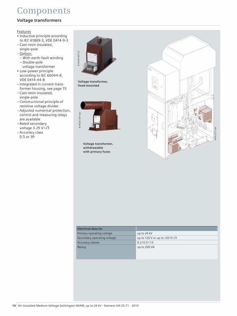
Voltage transformers
Components
Features• Inductive principle according
to IEC 61869-3, VDE 0414-9-3– Cast-resin insulated,
single-pole– Option:
– With earth-fault winding– Double-pole voltage transformer
• Low-power principle according to IEC 60044-8, VDE 0414-44-8
– Integrated in current trans-former housing, see page 15
– Cast-resin insulated, single-pole
– Constructional principle of resistive voltage divider
– Adjusted numerical protection, control and measuring relays are available
– Rated secondary voltage 3.25 V /
– Accuracy class 0.5 or 3P.
Electrical data for
Primary operating voltage up to 24 kV
Secondary operating voltage up to 120 V or up to 120 V/ √3
Accuracy classes 0.2 / 0.5 /1.0
Rating up to 200 VA
Voltage transformer, withdrawable with primary fuses
Voltage transformer, fi xed-mounted
R-H
A2
5-3
57
ep
sR
-HG
24-0
57
tif
HA
25
-27
21
eps
17Air-Insulated Medium-Voltage Switchgear NXAIR, up to 24 kV · Siemens HA 25.71 · 2014
Low-voltage compartment
Components
Features• Low-voltage compartment for
accommodation of all protec-tion, control, measuring and metering equipment
• Partitioned safe-to-touch off the high-voltage part
• Low-voltage compartment can be removed, as all bus wires and control cables are plugged in
• Option: Test sockets for capacitive voltage detecting system at the feeders or the busbar
• Option: Higher low-voltage compartment
• Option: Separation wall from panel to panel
• Low-voltage cables are fl ex-ible and protected by metal covers
• Connection of withdrawable part and panel wiring to low-voltage compartment via 10-pole, coded plug connectors
• Bus wires are pluggable from panel to panel.
Low-voltage compartment with built-in equipment (example)
R-H
A2
5-3
60
ep
sR
-HA
25
-292
a ep
s
Door of low-voltage compartment (example)
HA
25
-27
22
eps
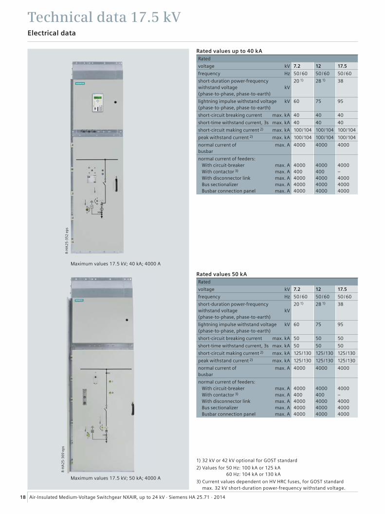
Maximum values 17.5 kV; 40 kA; 4000 A
Maximum values 17.5 kV; 50 kA; 4000 A
R-H
A2
5-3
52
ep
sR
-HA
25
-36
9 e
ps
18 Air-Insulated Medium-Voltage Switchgear NXAIR, up to 24 kV · Siemens HA 25.71 · 2014
Technical data 17.5 kVElectrical data
Rated values up to 40 kARated
voltage kV 7.2 12 17.5
frequency Hz 50 / 60 50 / 60 50 / 60
short-duration power-frequency withstand voltage kV(phase-to-phase, phase-to-earth)
20 1) 28 1) 38
lightning impulse withstand voltage kV(phase-to-phase, phase-to-earth)
60 75 95
short-circuit breaking current max. kA 40 40 40
short-time withstand current, 3s max. kA 40 40 40
short-circuit making current 2) max. kA 100 / 104 100 / 104 100 / 104
peak withstand current 2) max. kA 100 / 104 100 / 104 100 / 104
normal current of max. Abusbar
4000 4000 4000
normal current of feeders: With circuit-breaker max. A With contactor 3) max. A With disconnector link max. A Bus sectionalizer max. A Busbar connection panel max. A
4000400400040004000
4000400400040004000
4000–400040004000
Rated values 50 kARated
voltage kV 7.2 12 17.5
frequency Hz 50 / 60 50 / 60 50 / 60
short-duration power-frequency withstand voltage kV(phase-to-phase, phase-to-earth)
20 1) 28 1) 38
lightning impulse withstand voltage kV(phase-to-phase, phase-to-earth)
60 75 95
short-circuit breaking current max. kA 50 50 50
short-time withstand current, 3s max. kA 50 50 50
short-circuit making current 2) max. kA 125 / 130 125 / 130 125 / 130
peak withstand current 2) max. kA 125 / 130 125 / 130 125 / 130
normal current of max. Abusbar
4000 4000 4000
normal current of feeders: With circuit-breaker max. A With contactor 3) max. A With disconnector link max. A Bus sectionalizer max. A Busbar connection panel max. A
4000400400040004000
4000400400040004000
4000–400040004000
1) 32 kV or 42 kV optional for GOST standard
2) Values for 50 Hz: 100 kA or 125 kA 60 Hz: 104 kA or 130 kA
3) Current values dependent on HV HRC fuses, for GOST standard max. 32 kV short-duration power-frequency withstand voltage.
HA
25-2
658g
eps
2)
HA
25-2
659f
eps
2)
���
����
��
��
HA
25
-27
01
ep
s
���
����
���
��
Metering panel
or
or
and/or
19Air-Insulated Medium-Voltage Switchgear NXAIR, up to 24 kV · Siemens HA 25.71 · 2014
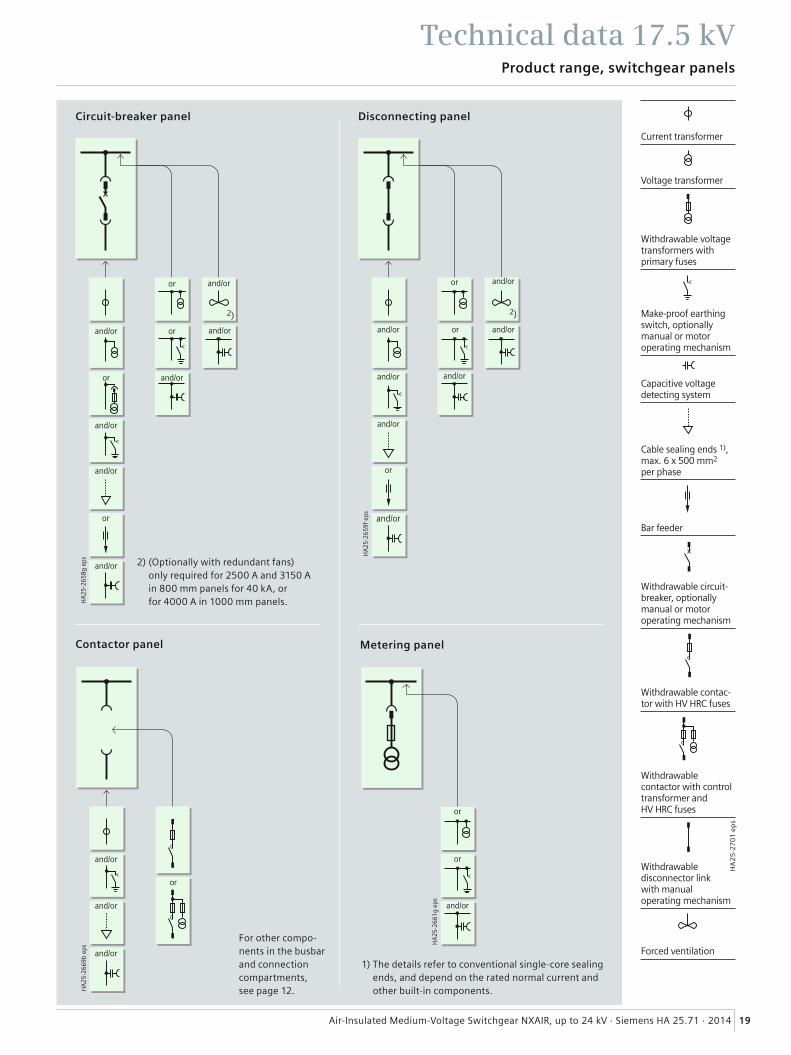
Product range, switchgear panels
Technical data 17.5 kV
1) The details refer to conventional single-core sealing ends, and depend on the rated normal current and other built-in components.
For other compo-nents in the busbar and connection compartments, see page 12.
Circuit-breaker panel
Contactor panel
Disconnecting panel
and/or
and/or
and/or and/or and/or
and/oror or
and/or and/or
and/or and/or
and/or or
and/or
and/or
and/or
and/or
and/or
or and/or
or or
or
or
Current transformer
Voltage transformer
Withdrawable voltage transformers with primary fuses
Make-proof earthing switch, optionally manual or motor operating mechanism
Capacitive voltage detecting system
Cable sealing ends 1), max. 6 x 500 mm2 per phase
Bar feeder
Withdrawable circuit-breaker, optionally manual or motor operating mechanism
Withdrawable contac-tor with HV HRC fuses
Withdrawable contactor with control transformer and HV HRC fuses
Withdrawable disconnector link with manual operating mechanism
Forced ventilation
2) (Optionally with redundant fans) only required for 2500 A and 3150 A in 800 mm panels for 40 kA, or for 4000 A in 1000 mm panels.
HA
25-2
662h
eps
1)
2)
2)1)
2)
4) 4)
���
����
���
��
HA
25-2
707b
eps
and/or
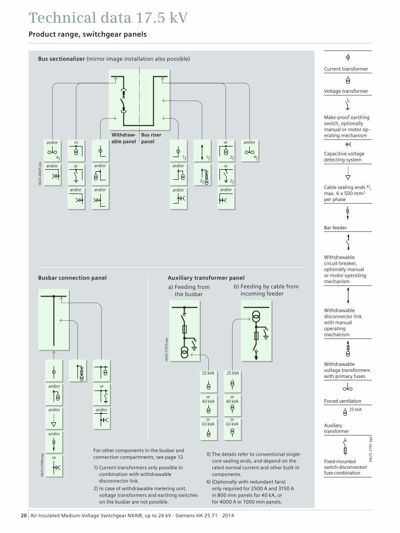
20 Air-Insulated Medium-Voltage Switchgear NXAIR, up to 24 kV · Siemens HA 25.71 · 2014
Product range, switchgear panels
Technical data 17.5 kV
For other components in the busbar and connection compartments, see page 12.
1) Current transformers only possible in combination with withdrawable disconnector link.
2) In case of withdrawable metering unit, voltage transformers and earthing switches on the busbar are not possible.
3) The details refer to conventional single-core sealing ends, and depend on the rated normal current and other built-in components.
4) (Optionally with redundant fans) only required for 2500 A and 3150 A in 800 mm panels for 40 kA, or for 4000 A in 1000 mm panels.
Bus sectionalizer (mirror-image installation also possible)
Busbar connection panel
b) Feeding by cable from incoming feeder
a) Feeding from the busbar
Auxiliary transformer panel
or
and/or
Withdraw-able panel
Bus riser panel
and/orand/or
and/or
and/or
and/or
or
and/or
or
and/or
and/or
or
and/or and/or
and/or
25 kVA
or 40 kVA
or 63 kVA
or 40 kVA
or 63 kVA
25 kVA
25 kVA
or
or
Current transformer
Voltage transformer
Make-proof earthing switch, optionally manual or motor op-erating mechanism
Capacitive voltage detecting system
Cable sealing ends 3), max. 6 x 500 mm2 per phase
Bar feeder
Withdrawable circuit-breaker, optionally manual or motor operating mechanism
Withdrawable disconnector link with manual operating mechanism
Withdrawable voltage transformers with primary fuses
Forced ventilation
Auxiliarytransformer
Fixed-mounted switch-disconnector/fuse combination
HA
25
-27
01
ep
s
21Air-Insulated Medium-Voltage Switchgear NXAIR, up to 24 kV · Siemens HA 25.71 · 2014
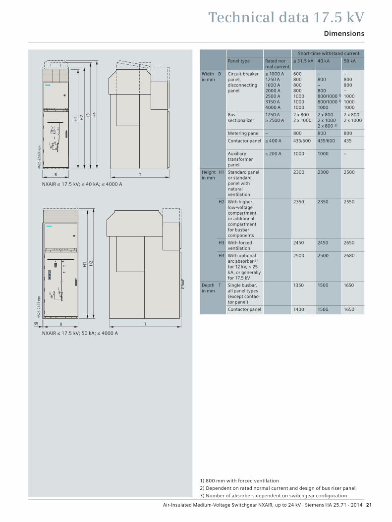
Technical data 17.5 kV Dimensions
Short-time withstand current
Panel type Rated nor-mal current
≤ 31.5 kA 40 kA 50 kA
Width Bin mm
Circuit-breakerpanel, disconnecting panel
≤ 1000 A1250 A1600 A2000 A2500 A3150 A4000 A
600800800800100010001000
–800–800800/1000 1)
800/1000 1)
1000
–800800–100010001000
Bus sectionalizer
1250 A≥ 2500 A
2 x 8002 x 1000
2 x 8002 x 10002 x 800 2)
2 x 8002 x 1000
Metering panel – 800 800 800
Contactor panel ≤ 400 A 435/600 435/600 435
Auxiliary transformer panel
≤ 200 A 1000 1000 –
Heightin mm
H1 Standard panel or standard panel with natural ventilation
2300 2300 2500
H2 With higher low-voltage compartment or additional compartment for busbar components
2350 2350 2550
H3 With forced ventilation
2450 2450 2650
H4 With optional arc absorber 3) for 12 kV, > 25 kA, or generally for 17.5 kV
2500 2500 2680
Depthin mm
T Single busbar, all panel types (except contac-tor panel)
1350 1500 1650
Contactor panel 1400 1500 1650
1) 800 mm with forced ventilation
2) Dependent on rated normal current and design of bus riser panel
3) Number of absorbers dependent on switchgear confi guration
��
��
��
����
����
��
�� �
��
�
���
�� ��
�
�
���
����
��
NXAIR ≤ 17.5 kV; ≤ 40 kA; ≤ 4000 A
NXAIR ≤ 17.5 kV; 50 kA; ≤ 4000 A

22 Air-Insulated Medium-Voltage Switchgear NXAIR, up to 24 kV · Siemens HA 25.71 · 2014
�� ��
���
���
����
��
�
��
������ ������
����
��
Pressure relief out of the switchgear roomthrough a pressure relief duct
Pressure relief into the switchgear room through absorbers
Rear pressure relief duct Lateral pressure relief duct
Room planning
Technical data 17.5 kV
1) For connection from the front ≥ 150 mm, 100 mm for contactor panel; for connection from the rear ≥ 500 mm
2) For designs with a closed pressure relief duct to the outside, a distance of ≥ 500 mm is required on one side
Rated voltage Ceiling height D in mm for short-circuit current
Type of pressure relief 25 kA 31.5 kA 40 kA 50 kA
Pressure relief into the switchgear room through absorbers 12 kV17.5 kV
≥ 2800≥ 3500
≥ 3000≥ 3500
≥ 3500≥ 3500
≥ 3500≥ 3500
Pressure relief out of the switchgear roomthrough a pressure relief duct
≤ 17.5 kV ≥ 2500 ≥ 2500 ≥ 2500 ≥ 2700
Width of control aisle E (min.) ≤ 17.5 kV 1250 1250 1250 1350
�
�
���
����
��
�
�
���
����
��
�
�
���
����
��
Single-row arrangement (plan view)for single-busbar switchgear
For dimensions B (width) and T (depth), see table on page 21
For back-to-back and face-to-face arrangement, the room dimensions apply accordingly to those for single-row arrangement.
For back-to-back arrangement, a 1200 mm wide control aisle is required on the left or on the right of the switchgear.

23Air-Insulated Medium-Voltage Switchgear NXAIR, up to 24 kV · Siemens HA 25.71 · 2014
Transport and packing
Technical data 17.5 kV
NXAIR up to 40 kATransport dimensions, transport weights 7) for individual panels
Panel widths Transport dimensionsWidth x Height x Depth
Transport weight with without packing packing
mm mm × mm × mm approx. kg approx. kg
Transport by rail or truck
1 × 435 800 x 2510 x 1610 750 720
1 × 600 800 x 2510 x 1610 900 870
1 × 800 1000 x 2510 x 1610 1175 1140
1 × 1000 1200 x 2510 x 1610 1410 1370
Transport by seafreight or airfreight
1 × 435 820 × 2541 × 1830 850 720
1 × 600 820 × 2541 × 1830 1000 870
1 × 800 1020 × 2541 × 1830 1285 1140
1 × 1000 1220 × 2541 × 1830 1525 1370
NXAIR up to 50 kATransport dimensions, transport weights 1) for individual panels
Panel widths Transport dimensionsWidth x Height x Depth
Transport weight with without packing packing
mm mm × mm × mm approx. kg approx. kg
Transport by rail or truck
1 × 435 800 x 2650 x 1850 780 750
1 × 800 900 x 2650 x 1850 1440 1400
1 × 1000 1100 x 2650 x 1850 1640 1600
1 × 1000 3) 1100 x 2650 x 1850 1640 1600
Transport by seafreight or airfreight
1 × 435 822 × 2661 × 1872 865 750
1 × 800 1022 × 2661 × 1872 1570 1400
1 × 1000 1222 × 2661 × 1872 1780 1600
1 × 1000 3) 1222 × 2661 × 1872 1755 1600
TransportNXAIR 17.5 kV switchgear is delivered in form of individual panels.Please observe the following:• Transport facilities on site• Transport dimensions and transport weights• Size of door openings in building.
PackingMeans of transport: Rail and truck– Panels on pallets– Open packing with
PE protective foil.
Means of transport: Seafreight– Panels on pallets– Sealed in PE protective foil, with closed wooden crate– With desiccant bags– With sealed wooden base– Max. storage time: 6 months.
Means of transport: Airfreight– Panels on pallets– In wooden latticed crate with sealed upper and lower
PE protective foil.
These transport and packing stipulations apply to the complete NXAIR product family. More information to transport dimensions / transport weights is given in the corresponding table.
1) Average values depending on the degree to which panels are equipped
2) Pressure relief ducts as separate delivery for 10 panels each (W 1100 x H 2000 x D 1800)
3) 4000 A panels (with forced ventilation)

24 Air-Insulated Medium-Voltage Switchgear NXAIR, up to 24 kV · Siemens HA 25.71 · 2014
Maximum values 24 kV; 25 kA; 2500 A
Motor-operated panel
R-H
A2
5-3
53
ep
s
Technical data 24 kVElectrical data
1) 65 kV optional for GOST standard
2) Values for 50 Hz: 63 kA, 60 Hz: 65 kA
Rated valuesRated
voltage kV 24
frequency Hz 50 / 60
short-duration power-frequency withstand voltage kV(phase-to-phase, phase-to-earth)
50 1)
lightning impulse withstand voltage kV(phase-to-phase, phase-to-earth)
125
short-circuit breaking current max. kA 25
short-time withstand current, 3s max. kA 25
short-circuit making current 2) max. kA 63 / 65
peak withstand current 2) max. kA 63 / 65
normal current of busbar max. A 2500
normal current of feeders: With circuit-breaker max. A With withdrawable disconnector link max. A Bus sectionalizer max. A
250025002500
R-H
A2
5-3
70
ep
s

HA
25-2
664h
eps
HA
25-2
665g
eps
25Air-Insulated Medium-Voltage Switchgear NXAIR, up to 24 kV · Siemens HA 25.71 · 2014
Product range, switchgear panels
Technical data 24 kV
For other components in the busbar and connection compartments, see page 12.
1) The details refer to conventional single-core sealing ends, and depend on the rated normal current and other built-in components.
Circuit-breaker panel Disconnecting panel
and/or and/or
and/or
and/or
and/or
and/or
and/or
and/or
and/orand/or
or
and/or
and/or
or
or
or
or
���
����
����
�
Metering panel
HA
25-2
704a
eps
���
����
���
��
Switch panel Auxiliary transformer panel
or
or or
and/or
and/or
and/or
Current transformer
Voltage transformer
Make-proof earthing switch, optionally manual or motor op-erating mechanism
Earthing switch
Capacitive voltage detecting system
Cable sealing ends 1), max. 4 x 500 mm2 per phase
Bar feeder
Withdrawable circuit-breaker, optionally manual or motor op-erating mechanism
Withdrawable disconnector link, optionally manual or motor operating mechanism
HV HRC fuse
Withdrawable metering unit with withdrawable voltage transformers
Withdrawable HV HRC fuses
Withdrawable volt-age transformers with primary fuses
HA
25
-27
01
ep
s
and/or
and/orand
and/or
and/or
and/or
���
����
��
� �
�� ��
��
��
��
��
HA
25-2
708c
eps
SS A
SS B
and/or and/or
or
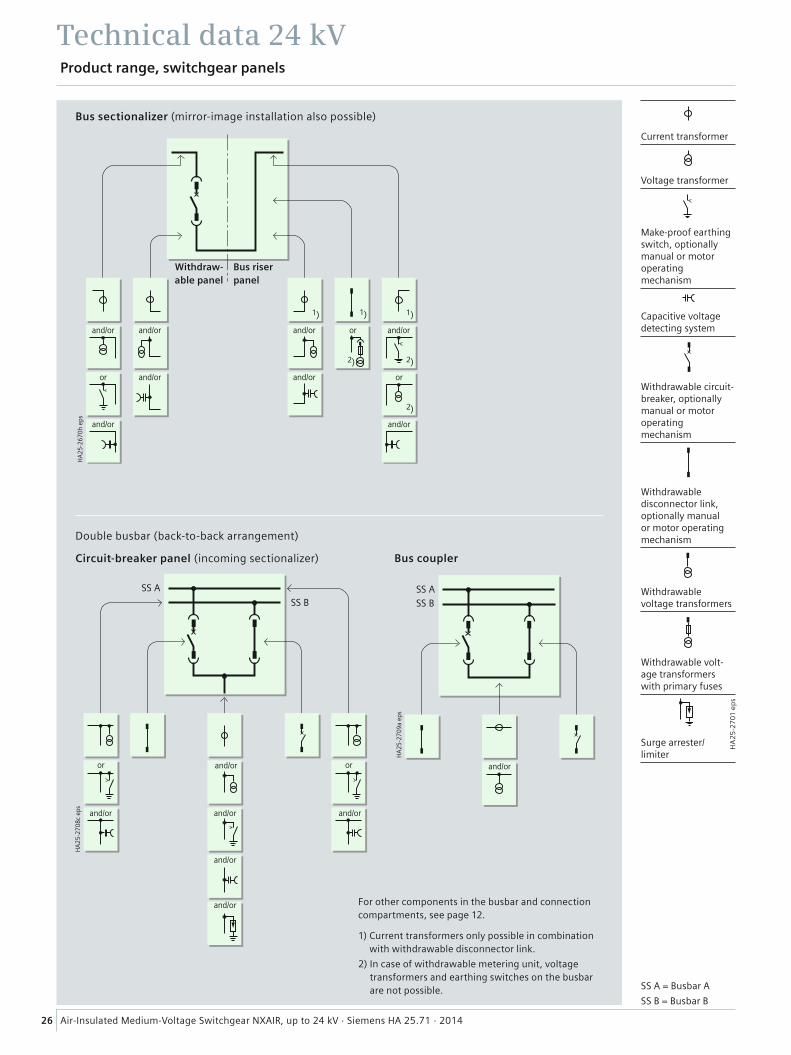
26 Air-Insulated Medium-Voltage Switchgear NXAIR, up to 24 kV · Siemens HA 25.71 · 2014
Product range, switchgear panels
Technical data 24 kV
For other components in the busbar and connection compartments, see page 12.
1) Current transformers only possible in combination with withdrawable disconnector link.
2) In case of withdrawable metering unit, voltage transformers and earthing switches on the busbar are not possible.
Bus sectionalizer (mirror-image installation also possible)
Circuit-breaker panel (incoming sectionalizer)
Double busbar (back-to-back arrangement)
Withdraw-able panel
Bus riser panel
and/or and/or
and/or and/or or
and/or
or
and/or
and/or
and/or
and/or
and/or
or
or
Current transformer
Voltage transformer
Make-proof earthing switch, optionally manual or motor operating mechanism
Capacitive voltage detecting system
Withdrawable circuit-breaker, optionally manual or motor operating mechanism
Withdrawable disconnector link, optionally manual or motor operating mechanism
Withdrawable voltage transformers
Withdrawable volt-age transformers with primary fuses
Surge arrester/limiter
HA
25
-27
01
ep
s
and/or and/or
HA
25-2
709a
eps
SS ASS B
Bus coupler
and/or
SS A = Busbar A
SS B = Busbar B
27Air-Insulated Medium-Voltage Switchgear NXAIR, up to 24 kV · Siemens HA 25.71 · 2014
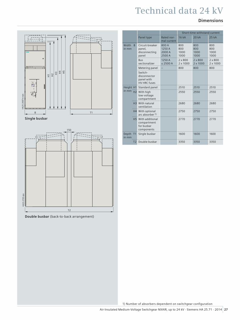
Technical data 24 kV Dimensions
HA
25
-26
87
m e
ps
H1 H2
T1B
H5
H4
H3
Single busbar
Double busbar (back-to-back arrangement)
T2
150
HA
25-2
705
eps
Short-time withstand current
Panel type Rated nor-mal current
16 kA 20 kA 25 kA
Width Bin mm
Circuit-breakerpanel, disconnecting panel
800 A1250 A2000 A2500 A
80080010001000
80080010001000
80080010001000
Bus sectionalizer
1250 A≤ 2500 A
2 x 8002 x 1000
2 x 8002 x 1000
2 x 8002 x 1000
Metering panel – 800 800 800
Switch-disconnector panel with HV HRC fuses
Heightin mm
H1 Standard panel 2510 2510 2510
H2 With high low-voltage compartment
2550 2550 2550
H3 With natural ventilation
2680 2680 2680
H4 With optional arc absorber 1)
2750 2750 2750
H5 With additional compartment for busbar components
2770 2770 2770
Depthin mm
T1 Single busbar 1600 1600 1600
T2 Double busbar 3350 3350 3350
1) Number of absorbers dependent on switchgear confi guration
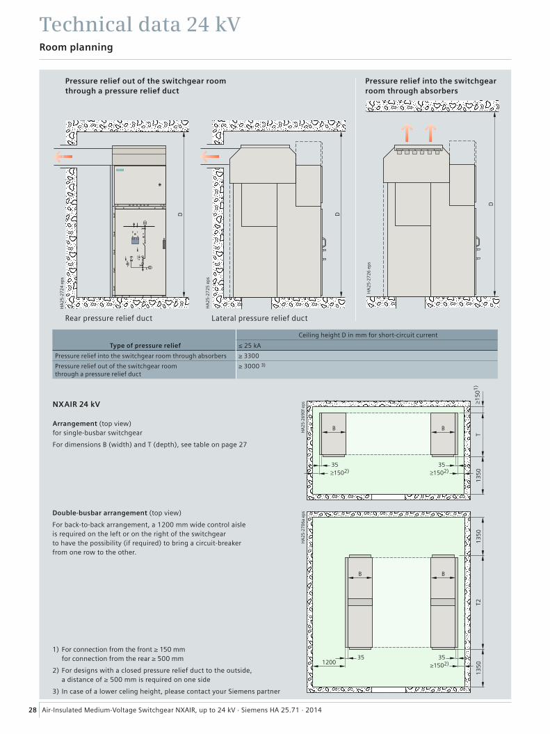
28 Air-Insulated Medium-Voltage Switchgear NXAIR, up to 24 kV · Siemens HA 25.71 · 2014
Room planning
Technical data 24 kV
1) For connection from the front ≥ 150 mm for connection from the rear ≥ 500 mm
2) For designs with a closed pressure relief duct to the outside, a distance of ≥ 500 mm is required on one side
3) In case of a lower celing height, please contact your Siemens partner
Ceiling height D in mm for short-circuit current
Type of pressure relief ≤ 25 kA
Pressure relief into the switchgear room through absorbers ≥ 3300
Pressure relief out of the switchgear roomthrough a pressure relief duct
≥ 3000 3)
���
����
��
�
�� ��
���
�
��
����� �������
���
NXAIR 24 kV
Arrangement (top view)for single-busbar switchgear
For dimensions B (width) and T (depth), see table on page 27
Double-busbar arrangement (top view)
For back-to-back arrangement, a 1200 mm wide control aisle is required on the left or on the right of the switchgear to have the possibility (if required) to bring a circuit-breaker from one row to the other.
Pressure relief out of the switchgear roomthrough a pressure relief duct
Pressure relief into the switchgear room through absorbers
Rear pressure relief duct Lateral pressure relief duct
�
��
����
��
��
�
��
����
���
��
�
��
����
���
��
Transport dimensions, transport weights 1) for individual panels 2)
Panel widths Transport dimensionsWidth x Height x Depth
Transport weight with without packing packing
mm mm × mm × mm approx. kg approx. kg
Transport by rail or truck
1 × 800 1200 x 2980 4) x 1810 1340 1200
1 × 1000 1200 x 2980 4) x 1810 1440 1400
Transport by seafreight or airfreight 3)
1 × 800 1200 × 2500 × 2000 1410 1250
1 × 1000 1200 × 2500 × 2000 1410 1250
29Air-Insulated Medium-Voltage Switchgear NXAIR, up to 24 kV · Siemens HA 25.71 · 2014
Technical data 24 kVTransport and packing
TransportNXAIR 24 kV switchgear is delivered in form of individual panels.Please observe the following:• Transport facilities on site• Transport dimensions and transport weights• Size of door openings in building.
PackingMeans of transport: Rail and truck– Panels on pallets– Open packing with PE protective foil.
Means of transport: Seafreight– Panels on pallets– Sealed in PE protective foil, with closed wooden crate– With desiccant bags– With sealed wooden base– Max. storage time: 6 months.
Means of transport: Airfreight– Panels on pallets– In wooden latticed crate with sealed upper and lower
PE protective foil.
These transport and packing stipulations apply to the complete NXAIR product family. More information to transport dimensions / transport weights is given in the corresponding table.
1) Average values depending on the degree to which panels are equipped
2) The double-busbar panels (back-to-back arrangement) are delivered as individual panels. Back-to-back connection is done on site
3) Pressure relief ducts or busbar components such as earthing switches or voltage transformers as separate delivery for 10 panels each (W 1100 x H 2000 x D 1800)
4) A height of 2450 mm is possible if the pressure relief duct is transported as a separate delivery
����������������
����
����
����
����
�������� ���� ����
����
���
��
��
����
���
���
�
30 Air-Insulated Medium-Voltage Switchgear NXAIR, up to 24 kV · Siemens HA 25.71 · 2014
Standards, specifi cations, guidelines
Standards
Overview of standards (August 2014)
IEC standard VDE standard DIN EN standard
Switchgear NXAIR IEC 62271-1 VDE 0671-1 DIN EN 62271-1
IEC 62271-200 VDE 0671-200 DIN EN 62271-200
Devices Circuit-breakers IEC 62271-100 VDE 0671-100 DIN EN 62271-100
Vacuum contactors IEC 62271-106 VDE 0671-106 DIN EN 62271-106
Disconnectors and earthing switches IEC 62271-102 VDE 0671-102 DIN EN 62271-102
Switch-disconnectors IEC 62271-103 VDE 0671-103 DIN EN 62271-103
Switch-disconnector/fuse combination
IEC 62271-105 VDE 0671-105 DIN EN 62271-105
HV HRC fuses IEC 60282-1 VDE 0670-4 DIN EN 60282-1
Voltage detecting systems IEC 61243-5 VDE 0682-415 DIN EN 61243-5
Degree of protection – IEC 60529 VDE 0470-1 DIN EN 60529
Insulation – IEC 60071 VDE 0111 DIN EN 60071
Instrument transformers
– IEC 61869-1 VDE 0414-9-1 DIN EN 61869-1
Current transformers IEC 61869-2 VDE 0414-9-2 DIN EN 61869-2
Voltage transformers IEC 61869-3 VDE 0414-9-3 DIN EN 61869-3
Installation, erection – IEC 61936-1 VDE 0101-1 DIN EN 61936-1
Type of service locationThe switchgear can be used as indoor installation according to IEC 61936 (Power Installations exceeding AC 1 kV) and VDE 0101• Outside lockable electrical service locations at places which
are not accessible to the public. Enclosures of switchgear can only be removed with tools
• In lockable electrical service locations. A lockable electri-cal service location is a place outdoors or indoors that is reserved exclusively for housing electrical equipment and which is kept under lock and key. Access is restricted to authorized personnel and persons who have been properly instructed in electrical engineering. Untrained or unskilled persons may only enter under the supervision of authorized personnel or properly instructed persons.
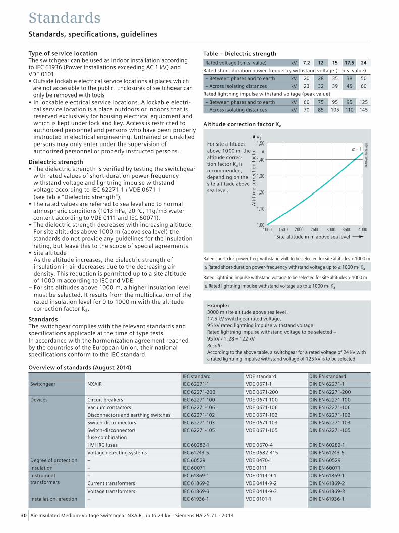
Dielectric strength• The dielectric strength is verifi ed by testing the switchgear
with rated values of short-duration power-frequency withstand voltage and lightning impulse withstand voltage according to IEC 62271-1 / VDE 0671-1 (see table “Dielectric strength“).
• The rated values are referred to sea level and to normal atmospheric conditions (1013 hPa, 20 °C, 11g /m3 water content according to VDE 0111 and IEC 60071).
• The dielectric strength decreases with increasing altitude. For site altitudes above 1000 m (above sea level) the standards do not provide any guidelines for the insulation rating, but leave this to the scope of special agreements.
• Site altitude– As the altitude increases, the dielectric strength of
insulation in air decreases due to the decreasing air density. This reduction is permitted up to a site altitude of 1000 m according to IEC and VDE.
– For site altitudes above 1000 m, a higher insulation level must be selected. It results from the multiplication of the rated insulation level for 0 to 1000 m with the altitude correction factor Ka.
StandardsThe switchgear complies with the relevant standards and specifi cations applicable at the time of type tests. In accordance with the harmonization agreement reached by the countries of the European Union, their national specifi cations conform to the IEC standard.
Example:3000 m site altitude above sea level, 17.5 kV switchgear rated voltage, 95 kV rated lightning impulse withstand voltageRated lightning impulse withstand voltage to be selected = 95 kV · 1.28 = 122 kVResult:According to the above table, a switchgear for a rated voltage of 24 kV with a rated lightning impulse withstand voltage of 125 kV is to be selected.
Rated short-dur. power-freq. withstand volt. to be selected for site altitudes > 1000 m
≥ Rated short-duration power-frequency withstand voltage up to ≤ 1000 m· Ka
Rated lightning impulse withstand voltage to be selected for site altitudes > 1000 m
≥ Rated lightning impulse withstand voltage up to ≤ 1000 m· Ka
Table – Dielectric strength
Rated voltage (r.m.s. value) kV 7.2 12 15 17.5 24
Rated short-duration power-frequency withstand voltage (r.m.s. value)
– Between phases and to earth kV 20 28 35 38 50
– Across isolating distances kV 23 32 39 45 60
Rated lightning impulse withstand voltage (peak value)
– Between phases and to earth kV 60 75 95 95 125
– Across isolating distances kV 70 85 105 110 145
For site altitudes above 1000 m, the altitude correc-tion factor Ka is recommended, depending on the site altitude above sea level.
Altitude correction factor Ka
Alt
itu
de
corr
ecti
on
fac
tor
Site altitude in m above sea level
31Air-Insulated Medium-Voltage Switchgear NXAIR, up to 24 kV · Siemens HA 25.71 · 2014
Standards, specifi cations, guidelines
Standards
Current carrying capacity• According to IEC 62271-1 / VDE 0671-1 and IEC 62271-200 /
VDE 0671-200, the rated normal current refers to thefollowing ambient air temperatures:
– Maximum of 24-hour mean: + 35 °C– Maximum: + 40 °C• The rated normal current of the panels and busbars
depends on the ambient air temperature outside the enclosure.
Protection against solid foreign objects, electric shock and waterNXAIR fulfi lls according to the standards – IEC 62271-200– IEC 60529– VDE 0470-1– VDE 0671-200the following degrees of protection:
Climate and environmental infl uencesNXAIR switchgear is suitable for application in indoor installations under normal operating conditions as defi ned in IEC 62271-1, as follows:• Maximum value of ambient air temperature: + 40 °C,
of 24-hour mean: + 35 °C• Minimum value of ambient air temperature: –5 °C
–25 °C (on request)
• Site altitude ≤ 1000 m above sea level• Relative air humidity over 24 h: ≤ 95%,
over a month: ≤ 90%• No signifi cant pollution of the ambient air
(dust, gases, vapors, salts).The switchgear may be used, subject to possible additional measures, under the following additional environmental infl uences:
– Natural foreign materials– Chemically active pollutants– Small animals
and the climate classes:– 3K3– 3K5.
The climate classes are defi ned according to IEC 60721-3-3.
Seismic withstand capabilityNXAIR ≤ 17.5 kV and NXAIR 24 kV switchgear is tested in accordance with the following internationally accepted requirements: IEC 62271-210 (Draft), IEC 68-3-3, IEC 68-2-6, IEEE 693, UBC Division IV
Internal arc classifi cation• Protection of operating personnel by means of tests for
verifying the internal arc classifi cation• Internal arcing tests must be performed in accordance
with IEC 62271-200/VDE 0671-200• The switchgear complies with all criteria specifi ed in the
a.m. standards (page 30) for the basic version up to 50 kA.• NXAIR complies with the internal arc classifi cation:
IAC A FLR up to 50 kA, 1 s.This provides maximum personal safety for switchgear accessible from all sides.
• Defi nition of criteria:– Criterion 1
Correctly secured doors and covers do not open, limited deformations are accepted
– Criterion 2No fragmentation of the enclosure, no projection of small parts above 60 g
– Criterion 3No holes in accessible sides up to a height of 2 m
– Criterion 4No ignition of indicators due to hot gases
– Criterion 5The enclosure remains connected to its earthing point.
• Beyond the specifi cations of the above-mentioned standards, NXAIR switchgear up to 31.5 kA /1 s resp. 40 kA /0.1 s is optionally designed with confi nement of internal arcs to the respective compartment.
Terms“Make-proof earthing switches“ are earthing switches with short-circuit making capacity according to– IEC 62271-102 and– VDE 0671-102 / EN 62271-102.
Switchgear panel NXAIR ≤ 17.5 kV NXAIR 24 kV
Degree of protectionfor the enclosureoptionally
IP3XDIP4X, IP50, IP51
IP3XDIP4XIP50, IP51
Degree of protectionfor the enclosurewith ventilation
IP3XDIP4X
IP3XDIP4X
Degree of protectionfor the partitions
IP2X IP2X
Degree of protection for the enclosure against mechani-cal impacts from outside
IK07 IK07

Siemens AG
Energy Management
Medium Voltage & Systems
160 Herring Road
2113 Macquarie Park NSW
Australia
Siemens AG
Energy Management
Medium Voltage & Systems
Thane Belapur Road
40061 Thane
India
Siemens AG
Energy Management
Medium Voltage & Systems
Jalan Pulo MAS Utara Kav. B 67-68
Jakarta, 13210
Indonesia
Siemens AG
Energy Management
Medium Voltage & Systems
46 Newmarket Road
Randburg 2169
South Africa
Siemens AG
Energy Management
Medium Voltage & Systems
Mozartstraße 31 C
91052 Erlangen
Germany
www.siemens.com/nxair
E-mail: [email protected]
www.siemens.com/medium-voltage-switchgear
© 2014 Siemens. All rights reserved.
The information provided in this catalog contains descrip-tions or characteristics of performance which in case of actual use do not always apply as described or which may change as a result of further development of the products.
An obligation to provide the respective characteristics shall only exist if expressly agreed in the terms of contract.
Order No. IC1000-K1425-A811-B2-7600
Printed in Germany
KG 10.14 3.5 32 En | 7400 / 59934
Subject to change without prior notice.