air & liquid cooled pressure vacuum pumps - vacpump.com · air & liquid cooled pressure...
TRANSCRIPT
MASPORT HXL SERIES Air & Liquid Cooled Pressure Vacuum Pumps
Rebuild Manual
For Models:
HXL75V II HXL75F II HXL75WV II HXL75WF II HXL15V II HXL15F II HXL15WV II HXL15WF II HXL20WV II HXL400WV
MASPORT INCORPORATED
6140 McCormick Drive Phone (402) 466-8428
Lincoln, NE 68507 Fax (402) 466-8355
Toll Free 1(800) 228-4510
www.masportpump.com October 2010 © Masport Incorporated All Rights Reserved Part Number 90347

TABLE OF CONTENTS ........................................................................................................................................................ PAGE
WARNING! ........................................................................................................................................... 1
I. DISASSEMBLY ................................................................................................................................. 2
A. TOOL REQUIREMENTS .............................................................................................................. 2 B. INTEGRAL VALVE OR PORTING PLATE REMOVAL ............................................................ 3 C. MARKING PARTS (PRIOR TO DISASSEMBLY) ...................................................................... 4 D. END COVER REMOVAL ............................................................................................................. 4 E. VANE AND ROTOR REMOVAL ................................................................................................. 6
II. PARTS INSPECTION - CLEANING OR REPLACEMENT ...................................................... 7
A. VANES........................................................................................................................................... 7 B. BEARING AND BEARING SPACER REMOVAL ...................................................................... 7 C. ROTOR INSPECTION AND CLEANING .................................................................................... 8 D. BEARING AND BEARING SPACER INSTALLATION ............................................................ 9 E. END COVER INSPECTION AND CLEANING ......................................................................... 10 F. CYLINDER HOUSING INSPECTION AND CLEANING ......................................................... 12 G. INTEGRAL VALVE ASSEMBLY ............................................................................................. 14
III. PUMP ASSEMBLY ...................................................................................................................... 15
A. INSTALLING FIRST END COVER AND ENDCOVER SHIM GASKETS .............................. 15 B. INSTALLING ROTOR ASSEMBLY .......................................................................................... 16 C. INSTALLING SECOND END COVER ...................................................................................... 17 D. SETTING SEAL GAP ................................................................................................................. 18
SEAL GAP SPECIFICATIONS..................................................................................................... 18 OPTION 1 (LIMITED SPECIAL TOOLING): ............................................................................. 19 OPTION 2 (FACTORY METHOD UTILIZING SPECIAL TOOLING): ...................................... 19
E. CHECKING ROTOR END FLOAT ............................................................................................. 20 TOTAL ROTOR END FLOAT ...................................................................................................... 21 GASKET THICKNESS COLOR CODE ........................................................................................ 21
F. SETTING END-THRUST PROTECTION GRUBSCREWS....................................................... 21 END THRUST FROM COVER ..................................................................................................... 22
G. INSTALLING EXHAUST FLAP ASSEMBLY AND INTEGRAL VALVE.............................. 23 HXL75V FLAP INSTALLATION .................................................................................................. 23 HXL75WV FLAP INSTALLATION ............................................................................................... 23 HXL15WV, HXL20WV AND HXL400WV FLAP INSTALLATION .............................................. 24
H. FINAL CONNECTIONS ............................................................................................................. 24 I. PRE - INSTALLATION PUMP LUBRICATION ......................................................................... 25
PARTS LIST DRAWINGS: ...................................................................................................................... 26
HXL75F II ................................................................................................................................ 28 HXL75WV II ........................................................................................................................... 29 HXL75WF II ............................................................................................................................ 30 HXL15WV II ........................................................................................................................... 31 HXL15WF II ............................................................................................................................ 32 HXL15V II ............................................................................................................................... 33 HXL15F II ................................................................................................................................ 34 HXL20WV II ........................................................................................................................... 35 HXL400WV ............................................................................................................................. 36
GENUINE MASPORT PUMP SPARES KITS AND PACKS ............................................... 37
LIST OF OIL TYPES .............................................................................................................. 38
1
SAFETY WARNING:
BEFORE WORKING ON YOUR PUMP
READ THE MANUAL COMPLETELY
IDENTIFY - REMOVE - REDUCE ANY POTENTIAL HAZARDS
WARNING!
• Always use approved, safe working technique and equipment
• Vacuum pumps and main components are heavy
o Use only properly rated and certified lifting equipment
o Only trained operators should operate required machinery
o Use safe lifting techniques when manual lifting is required
Use two person lifting methods when required
• Pumps should be serviced on a stable, flat work-surface capable of safely holding the weights involved
o If turning a pump over, protect the operator and pump from damage by
always having the weight under control
Use a cover sheet to protect the machined surfaces of the pump from hard contact with the work-surface
• Always use all personal protective equipment required for the operation undertaken
• Only use properly maintained tools and equipment
o Work in a clean and safe, well lit work environment o Store removed parts so that they will not be damaged or get in the way
• Use only genuine Masport spare parts – confirm model and generation specifics of your pump at the time of ordering
• Read and be familiar with all aspects of this manual before undertaking work
on a pump
o Ascertain, as soon as practical, the degree of re-build required for each pump undertaken

2
I. DISASSEMBLY
A. TOOL REQUIREMENTS The following tools are required to properly service the Masport HXL Series pump.
• 3/8” or 1/2” Ratchet
• Sockets in sizes: 13mm, 16mm, 18mm
• Torque Wrenches (up to 75 ft. lbs.)
• Combination Wrenches 7/16”, 9/16”
• Allen Wrench 3/16” and 10mm
• Bearing Puller (Approximate reach 7”)
• Rubber Headed Mallet
• Ball Peen Hammer
• Small Center Punch
• Gasket Scraper or Putty Knife
• Needle Nose Pliers
• Parts Washing Pan and Brush
• Cleaning Solvent
• Oil Seal Driver or Metal Disc 2” in Diameter
• Flat Metal File
• Wet-Dry Sand Paper
• Bearing Press or 6” long 1 1/2” pipe nipple with cap
• Valve Lapping Compound
• Dial Indicator on stand, approx. travel 0.25” graduated in 0.0001” increments
NOTE: Not standard 0.001” graduations
• Pin Type Spanner Wrench with 3/16” pins
• Small container of grease
• Vacuum Pump Lubricant
• 8mm Modified Hand Reamer – grind off lead-in leaving about 5mm (3/16th”) of taper only, as per illustration above
• 7.5mm drill to suit M8 reamer (OR oversize reamer and drill to suit)

3
B. INTEGRAL VALVE OR PORTING PLATE REMOVAL
• Remove valve retaining bolts, tap valve with soft hammer to break gasket seal • HXL75V and HXL75WV integral valves are held in place by four 12mm bolts.
To free the valve from the gasket use a gasket scraper or putty knife. Remove the single exhaust flap from its slot after removing the valve
• HXL75 manifold plate is held down with the same bolts as the integral valve
• Water cooled Masport vacuum pumps have a porting or manifold plate under
the integral valve. The H75WV manifold plate is held down with the same bolts as the integral valve
• The HXL15WV, HXL20WV and HXL400WV manifold plate is held down with
ten 12mm socket head screws. Remove the valve, then the manifold plate and lift out the two exhaust flaps on these models. See typical layout detail below
Valve and Manifold Detail

4
C. MARKING PARTS (PRIOR TO DISASSEMBLY) Remove the 3 shaft guard retaining bolts from the non-drive end of the pump and remove the guard. Prior to further disassembly, mark the pump parts. This will help ensure the correct assembly of the vacuum pump. Two dowel pins in each of the end covers set the internal pump clearances. It is critical that the end covers be assembled back onto the side they originally came from as the pins and end covers are not the same. If not assembled to their original positions, the rotor clearance (seal gap *) and alignment to housing will not be correct and damage to the pump may occur. It is also important that the rotor be installed in the same direction as it was removed and not turned around in the cylinder. * For reference, check seal gap now – see process on page 18. Use a center punch and ball-peen hammer to place a mark on one of the end covers, the corresponding side of the cylinder housing, and the end of the rotor shaft.
D. END COVER REMOVAL Remove the oil pump and driveshaft before removing the end cover - long nose pliers or similar may be required to carefully grip the oil pump driveshaft to get it to slide out initially. If not replacing the drive spindle soak it in a cleaning solution while re-building the rest of the pump.
IMPORTANT: Before continuing disassembly of the vacuum pump, turn the
pump upside down on a suitable work surface. This is to prevent the offset rotor from dropping or becoming stuck in the cylinder causing damage to cylinder, rotor or covers.
USE AN OVERHEAD CRANE WITH A SUITABLE SLING OVER BOTH SHAFTS AND ROTATE PUMP OR USE A TWO PERSON MANUAL
METHOD TO TURN PUMP OVER

5
Remove the eight 16mm hex head end cover bolts, from one end of the pump.
Thread two of the end cover bolts, or longer bolts if available, into the end cover jacking holes. These are the tapped holes located on the end cover at the 2 o’clock and 7 o’clock positions. Turn the two bolts in evenly, 1/2 turn at a time. This will draw the end cover away from the cylinder housing.
When they are all the way in, using a rubber mallet, drive the end of the rotor shaft back in toward the other end cover. This should free the bearing from the end cover and allow the removal of the end cover.
DO NOT PRY OR HAMMER THE END COVER OFF THE CYLINDER BECAUSE THE SEALING SURFACES MAY BECOME
DAMAGED
NOTE: The overall end clearance (end float), is set with color coded shim
gaskets between the end cover and cylinder. Make note of the quantity and color of any gaskets when removing the end cover to allow replacement with the same color and quantity upon assembly.
ALWAYS CHECK COLOR, NUMBER AND PLACEMENT OF COVER GASKETS

6
E. VANE AND ROTOR REMOVAL With one of the end covers off, slide the vanes out of their slots. Remove the rotor assembly from the cylinder by driving the rotor out with a rubber mallet. Striking the rotor shaft on the end still in the end cover will force the bearing out of the end cover and free the assembly. Provide a pad such as a block of wood for the rotor to slide onto so it is not damaged.
Handle the rotor with care and remove safely to a cradle type rest for inspection.
CAUTION: The rotor is heavy; use appropriate lifting gear and technique.
A simple cradle like this one can be used to support the rotor while it is inspected and cleaned up. With the rotor and vanes removed, remove the second end cover using the same procedure used with the first one.

7
II. PARTS INSPECTION - CLEANING OR REPLACEMENT
A. VANES If a Repair Parts Kit is being installed and the vanes being replaced, inspect the old vanes for damage due to improper operation. Correct this condition upon installation of the pump. The old vanes may be reused if they meet the following criteria.
1. Measure the vane to see that it is no less than the minimum width for that model pump. (2 1/4” in width for models HXL75 & HXL15; 2 5/8” in width for model HXL20WV and HXL400WV). Also measure to see that the working edge and the edge in the rotor are parallel
2. Inspect the sides of the vanes to see that they are not bent or worn to a
concave shape on one side
3. Check the edge of the vane that contacts the cylinder for signs of resin breakdown. This will appear as gaps in the resin between the weave of the vane fiber
4. Inspect the sides of the vane for scratches or gouges. These would indicate foreign material caught alongside the vane, or a sharp edge on the rotor vane slot
IF A SINGLE VANE FAILS ANY OF THE ABOVE CHECKS THEN ALL VANES MUST BE REPLACED AS A COMPLETE SET
B. BEARING AND BEARING SPACER REMOVAL Before attempting bearing removal from the shaft, any burrs on the shaft or keyway from pulley set screws or other damage, must be removed with a flat file. Once the shaft is free of burrs the worm drive gear can be removed by loosening the grub screw and pulling off the gear, bearing and spacer as a group using a bearing puller of the type pictured below right. NOTE: Bearing spacers are not reusable and must be replaced when removed. The HXL400 bearings (no spacers are used on the HXL400), as pictured above left, can be removed by using the supplied jacking screws to start the bearing moving then the bearing puller can be used to complete the removal. Refit the jacking screws after removing the bearings, cleaning as required and locking in with a liquid thread retainer.

8
DO NOT INSTALL NEW BEARINGS AND SPACERS AT THIS TIME
FOLLOW THE ROTOR INSPECTION AND CLEANING INSTRUCTIONS FIRST
C. ROTOR INSPECTION AND CLEANING Inspect the edges of the vane slot across the length of the rotor and on the ends next to the bearing fit. All of these edges should be lightly filed or rubbed with emery to remove any burrs or nicks that may have been caused by foreign material or rotor to end cover contact.
If either of the bearings had failed and spun on the shaft, the shaft should be built-up and machined concentric to other diameters by a qualified machine shop to ensure proper transition bearing fit. Likewise any remedial machining of the rotor diameter or face must be precise and square and will require compensating for when the pump is rebuilt (seal gap or end-float). Remove any oil varnish or build-up with 400 grit wet/dry sandpaper. Clean the rotor with a solvent and dry it off, blow out any residue with compressed air.
Inspect the rotor carefully at this time for cracks, especially if tear down was due to pump seizure.
ANY CRACKS IN THE ROTOR WILL REQUIRE REPLACEMENT
OF THE PART

9
D. BEARING AND BEARING SPACER INSTALLATION NOTE: The bearing spacer must be installed facing in the correct direction. None are used on the HXL400. Looking carefully at the spacer, note that the hole bored for the shaft has a larger diameter on one side than the other. The spacer is installed on the rotor shaft with the larger bore and face diameter toward the rotor casting.
Spacer Placement
INCORRECT INSTALLATION OF THE SPACER WILL CAUSE
BEARING FAILURE AND DAMAGE TO THE PUMP
10
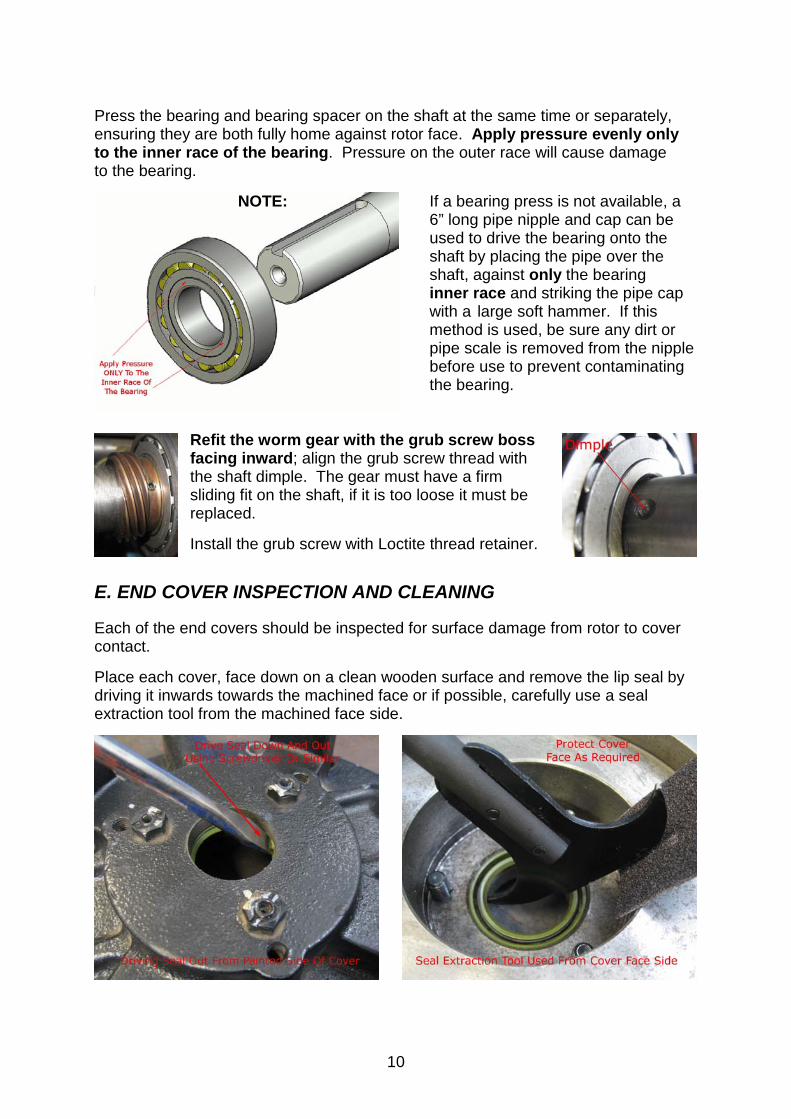
Press the bearing and bearing spacer on the shaft at the same time or separately, ensuring they are both fully home against rotor face. Apply pressure evenly only to the inner race of the bearing. Pressure on the outer race will cause damage to the bearing. NOTE: If a bearing press is not available, a
6” long pipe nipple and cap can be used to drive the bearing onto the shaft by placing the pipe over the shaft, against only the bearing inner race and striking the pipe cap with a large soft hammer. If this method is used, be sure any dirt or pipe scale is removed from the nipple before use to prevent contaminating the bearing.
Refit the worm gear with the grub screw boss facing inward; align the grub screw thread with the shaft dimple. The gear must have a firm sliding fit on the shaft, if it is too loose it must be replaced. Install the grub screw with Loctite thread retainer.
E. END COVER INSPECTION AND CLEANING Each of the end covers should be inspected for surface damage from rotor to cover contact. Place each cover, face down on a clean wooden surface and remove the lip seal by driving it inwards towards the machined face or if possible, carefully use a seal extraction tool from the machined face side.

11
The bearing housing should be inspected for signs of bearing spacer-to-bore contact or spinning of the bearing outer race in the bore - remove the 3 lock nuts and thrust setting grub screws from the covers.
IF THE BEARING HOUSING BORE IS DAMAGED DUE TO
SPACER CONTACT, IT CAN BE EASILY CLEANED UP WITH A SMALL FILE OR 180 – 320 WET/DRY SANDPAPER TO REMOVE
ANY BURRS
NOTE: If either of the bearings has seized and spun in the housing, the fit should be checked with a new bearing to ensure there is no excessive clearance.
THE NEW BEARING SHOULD SLIP SNUGLY IN THE HOUSING
WITH A SLIDING CLEARANCE FIT
If the end covers have been damaged by rotor-to-cover contact and there are grooves worn in the cover more than 0.005” deep, the face should be resurfaced. NOTE: If required to re-surface a cover, remove only the minimum material needed evenly to ensure bearing bore remains square with the cover face. Failure to do this could lead to premature bearing failure. If there is no damage or the damage is minor, the face of the cover should be wiped clean with solvent and then lapped with lapping compound against the other end cover surface. After lapping, the covers should again be wiped clean and blown off with an air hose to remove any traces of lapping compound that could cause damage on assembly. Be sure to clean any compound or foreign material from the bearing housing oil passage. New lip seals can now be fitted into housing. Install seal spring facing inwards with a mandrel or pipe, sized to press only on the outside diameter of the seal. Use a hand press if available or a soft hammer on a firm surface.
IF SETTING PUMP CLEARANCES WITH THE VANES OUT OF
THE PUMP ONE COVER MAY BE LEFT WITHOUT A SEAL, SELECTING THIS COVER TO REMOVE WHEN VANES ARE
INSTALLED – FIT SEAL BEFORE FINALLY MOUNTING COVER

12
F. CYLINDER HOUSING INSPECTION AND CLEANING Prior to inspection, the cylinder housing should be cleaned inside and out to allow a more thorough inspection. Special attention should be given to the areas inside the intake and exhaust ports of the cylinder.
IF THERE IS A SIZABLE BUILD-UP OF OIL SLUDGE IN THE
EXHAUST PORT, THE TYPE OF LUBRICANT USED IN THE UNIT SHOULD BE RECONSIDERED UPON INSTALLATION OF THE
REPAIRED PUMP
IF FOREIGN MATERIAL IS BUILT-UP IN THE INTAKE PORTING, THE PRIMARY AND SECONDARY SCRUBBER SYSTEM ON THE
TRUCK SHOULD BE CHECKED TO ENSURE THEY ARE IN PROPER WORKING ORDER AND ARE SIZED PROPERLY FOR
THE PUMP BEING USED
Inspect the interior of the cylinder for cracks, deep gouges around the circumference, and corrugation across the length of the bore.
CRACKS IN THE HOUSING QUALIFY THE PART FOR
REPLACEMENT
Gouges or grooves around the entire circumference of the cylinder indicate foreign material contamination, low volume or poor quality lubricating oil.
BORING OF THE CYLINDER IS REQUIRED IF GOUGES OR
GROOVES ARE MORE THAN 0.005” DEEP
If the grooves are shallow, new vanes will wear into them fairly quickly and provide reasonable results. NOTE: If a cylinder is re-bored it must be set up and machined square to the
face accurately or performance will be reduced.

13
Corrugation across the length of the cylinder bore can be caused by several things:
• Inadequate horsepower transfer
• Pump RPM is too slow
• Foreign material sticking the vanes in their slots causing hammering action on the cylinder
• Operation of the pump outside recommended operational speed
Each of these possible causes should be investigated and corrected before the pump is installed on the truck. If the corrugation is so slight as to be visible but not felt by running a finger over the bore, the cylinder can be cleaned and reused.
IF THE CORRUGATIONS ARE DEEP ENOUGH TO BE FELT THE CYLINDER SHOULD BE BORED, HONED AND THE SEAL GAP
CLEARANCE RESET
Assuming the cylinder is reusable, it should be cleaned thoroughly with solvent and have any sharp edges or burrs removed; carefully using a file and emery cloth.
AVOID ANY DAMAGE OR SIDE FORCE ON THE DOWEL PINS IF CLEARANCES ARE NOT REQUIRED TO BE RESET
If the cylinder bore is re-machined, follow the same process to clean and remove all burrs and sharp edges.
REMOVE DOWEL ONLY ON INLET SIDE OF PUMP, AT BOTH ENDS, IF RESETTING ROTOR TO CYLINDER CLEARANCE
THIS IS MANDATORY IF THE CYLINDER DIAMETER IS
ALTERED BY REMEDIAL MACHINING

14
G. INTEGRAL VALVE ASSEMBLY If the pump is fitted with an Integral Valve, it should be disassembled for cleaning and seal replacement. Prior to disassembly, the valve cap and valve body should be marked, to ensure assembly in the same position.
1. Remove the valve handle retaining bolt and valve handle
2. Removing the four valve cap retaining bolts will allow the Valve Cap to be removed. These four bolts should be removed evenly, alternating from one to another, to prevent binding between the oil seal in the valve cap and the valve spool stem
NOTE: The cap is under tension from an internal compression spring, caution must be exercised to contain the spring tension as the bolts are loosened.
3. Once the cap is removed, the valve spring and valve spool can be removed by turning it slightly in the valve bore and lifting it out. The valve cap oil seal can now be removed by driving it out of the bore from the inside of the cap out. Clean all the parts thoroughly. Press the new seal into the valve cap from the top with the spring side of the oil seal toward the inside of the cap – use a mandrel to guide the seal in, pushing only on the seal OD
4. Examining the inside of the valve spool cap will reveal a protruding valve
spool-stop cast into the side of the cap. This spool-stop must be aligned with the slot cast into the top of the valve spool. If not aligned, the valve will jam and not function properly
5. Smear anti-seize on spool taper and place it back in the valve body
6. Place the valve spring over the valve spool shaft
7. Grease the inside of the valve cap oil seal and place the valve cap on the valve spool shaft, taking care to line it up with the valve spool
8. Replace the valve cap retaining bolts and lock washers and tighten them down
evenly, to prevent binding on the shaft seal
9. Replace the valve handle, bolt, and retaining washer, and turn the valve handle to ensure proper function
15
III. PUMP ASSEMBLY
A. INSTALLING FIRST END COVER AND ENDCOVER SHIM GASKETS Be sure all the parts are cleaned and ready for assembly. The area to be used for assembly should be thoroughly cleaned to prevent contamination during assembly. If the pump needs any clearances reset then the cylinder and rotor should be installed free of oil so that clearances can accurately be set (* see exception on page 15).
IDEALLY ALL CLEARANCES SHOULD BE SET WITHOUT VANES
IN THE PUMP
Place cleaned cylinder housing upside down on the assembly table. Find the reference marks made before disassembly to determine the correct end cover for one end of the pump.
REMOVE DOWELS FROM INLET SIDE OF PUMP CYLINDER IF RESETTING SEAL GAP
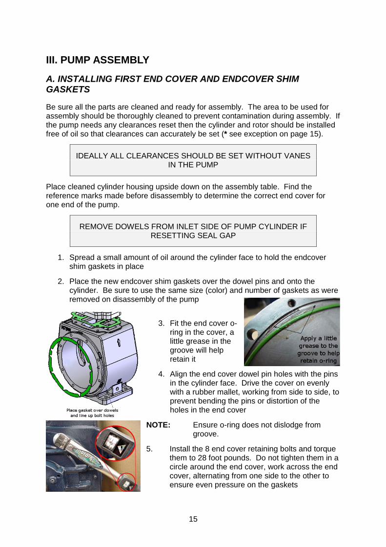
1. Spread a small amount of oil around the cylinder face to hold the endcover shim gaskets in place
2. Place the new endcover shim gaskets over the dowel pins and onto the
cylinder. Be sure to use the same size (color) and number of gaskets as were removed on disassembly of the pump
3. Fit the end cover o-ring in the cover, a little grease in the groove will help retain it
4. Align the end cover dowel pin holes with the pins
in the cylinder face. Drive the cover on evenly with a rubber mallet, working from side to side, to prevent bending the pins or distortion of the holes in the end cover
NOTE: Ensure o-ring does not dislodge from groove. 5. Install the 8 end cover retaining bolts and torque them to 28 foot pounds. Do not tighten them in a circle around the end cover, work across the end cover, alternating from one side to the other to ensure even pressure on the gaskets
16
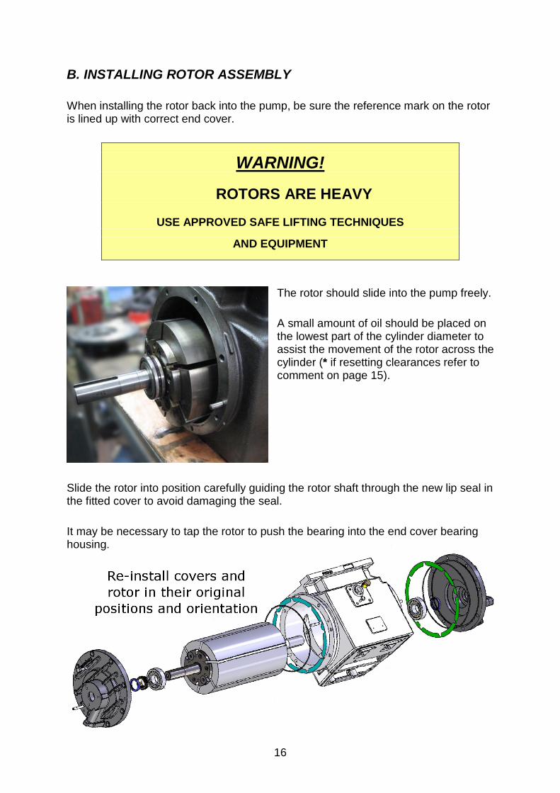
B. INSTALLING ROTOR ASSEMBLY When installing the rotor back into the pump, be sure the reference mark on the rotor is lined up with correct end cover.
WARNING!
ROTORS ARE HEAVY
USE APPROVED SAFE LIFTING TECHNIQUES
AND EQUIPMENT
The rotor should slide into the pump freely. A small amount of oil should be placed on the lowest part of the cylinder diameter to assist the movement of the rotor across the cylinder (* if resetting clearances refer to comment on page 15).
Slide the rotor into position carefully guiding the rotor shaft through the new lip seal in the fitted cover to avoid damaging the seal. It may be necessary to tap the rotor to push the bearing into the end cover bearing housing.

17
C. INSTALLING SECOND END COVER Fit endcover shim gaskets on to remaining cylinder end face and o-ring in cover groove as per the first cover fitting instructions. Place the second end cover over the rotor shaft; be sure to lift the cover gently away from the shaft keyway to avoid damaging the lip seal. When it contacts the cover start the bearing into the cover housing. It will be necessary to lift the cover and rotor slightly, in order to align the dowel pins and dowel pin holes.
Once the pins are aligned, the end cover can be driven evenly against the cylinder face with a rubber mallet. The end cover bolts can now be installed and torqued according to the procedure in “Installing First End Cover” on page 15. The rotor should turn freely in the cylinder. Only rotate it enough to determine if it turns freely. If it does not, either one of the vanes (if installed) is in crooked and caught on a bearing spacer, or the rotor is jammed against one of the covers, due to a bearing or spacer sticking in the end cover bore.
NOTE: Before disassembling to check for one of these problems, strike each end of the rotor shaft lightly with a rubber mallet. If this does not cure the problem, disassemble the pump according to the “End Cover Removal” section on page 4 and correct the problem.
DO NOT ROTATE A DRY CYLINDER AND ROTOR
UNNECESSARILY
CAUTION: Under no circumstances should the rotor be forced to turn with any type
of tool, or damage will be done to the pump.

18
D. SETTING SEAL GAP At this point, the lower pump assembly is complete and the seal gap clearance between the rotor and cylinder should be checked or set as required.
TURN THE PUMP BACK OVER ON TO ITS BASE TO CHECK
CLEARANCES
The seal gap is the distance between the outer diameter of the rotor and the top of the inside of the cylinder bore.
SEAL GAP SPECIFICATIONS – (Units in inches)
HXL75F and HXL75V 0.005 + 0.003 - 0.000
HXL75WF and HXL75WV 0.008 + 0.002
- 0.000
HXL15F and HXL15V 0.008 + 0.002 - 0.000
HXL15WF and HXL15WV 0.008 + 0.002
- 0.000
HXL20WV 0.008 + 0.002 - 0.000
HXL400WV 0.008 + 0.002
- 0.000 This clearance can be checked by inserting the proper sized feeler gauge in the exhaust port of the pump across the top of the rotor to the inlet side of the pump.
THE ROTOR SHOULD BE TURNED SO THAT NONE OF THE
VANE SLOTS ARE AT THE TOP OF THE CYLINDER
The clearance should be checked at three points if possible; in the center of the pump, and at each end of the rotor near the end cover, to ensure the rotor is parallel with the cylinder bore. If the clearance is within specification, the dowel pins will not have to be replaced. Note: If the setting is within 0.001” from end to end then it can be considered within specification.
If setting the seal gap is required; either of the two following technique options can be implemented:
REMEMBER: Inlet side dowel pins should have been removed for this process.
STANDARD DOWELS ARE M8 X 30MM HARDENED & GROUND

19
OPTION 1 (LIMITED SPECIAL TOOLING):
• Place correct size feeler gauges in position
• Turn pump upside down
• Loosen all cover bolts
• Allow the covers to pivot the rotor down, on the exhaust side dowel pins, to contact the feeler gauges
• Re-torque cover bolts evenly to 28 Ft/Lb
• Turn pump over and re-check seal gap – repeat process if required
• Cover the top of the pump with masking tape to prevent foreign material from entering
• Drill and ream (use modified reamer as detailed on page 2) for new oversize dowels or reposition original 8mm dowels – this operation must be square to the cylinder
• Clear swarf from hole & fit the dowels to secure the setting Drill for new dowel (Note the use of tape to set depth required) Ream by hand
OPTION 2 (FACTORY METHOD UTILIZING SPECIAL TOOLING):
• Use dial indicators on the covers to accurately measure the seal gap
• With the pump right side up, pivot the covers up slowly to allow the rotor to make light contact with the cylinder
• Zero the Dial Indicators in contact with the end covers and then allow the covers to pivot gently down, as the rotor goes from contact with the cylinder to the seal gap setting, the movement can be stopped and the seal gap confirmed on the Dial Indicator dials
• Evenly re-torque the cover bolts when the gap is correct, confirming setting with feeler gauges
• Cover the top of the pump with masking tape to prevent foreign material from entering
• As above, drill, ream to depth of dowel, clean out hole and fit the dowels NOTE: All of the setting is done without oil on the cylinder or rotor except for the small amount used during the installation of the rotor. Care must be taken to not rotate the pump unnecessarily during the setting process, particularly when the rotor is in contact with the cylinder.

20
E. CHECKING ROTOR END FLOAT The following operation will require the use of a dial indicator and either a magnetic stand or a stand that can be bolted to one of the end cover bolts.
THE INDICATOR STAND MUST BE MOUNTED DIRECTLY TO THE
PUMP ITSELF OR THE READINGS WILL BE INACCURATE
1. Mount the dial indicator stand on the pump end cover and attach the dial indicator so that the end of the indicator is on the end of the pump shaft NOTE: The travel axis of the indicator must be on the same line as the axis of the pump shaft.
THE FACTORY SET UP IS PICTURED ABOVE, SHOWING A DIAL
INDICATOR AND SPECIAL TOOL FOR LIFTING THE ROTOR
PULLEYS OR COLLARS FITTED TO THE SHAFTS, LEVERED WITH SCREWDRIVERS, MAY BE USED INSTEAD
2. Push the rotor firmly until it becomes tight, indicating the rotor has been pushed up against one of the end covers
3. Zero the Dial Indicator
4. Push the rotor back firmly against the other end cover, note the Dial Indicator reading
5. The difference between the two readings is the total amount of end float 6. Check it against the following table to see that it is within specification for the
pump being worked on 7. If the clearance is too little, an end cover will have to be removed and
endcover shim gaskets added to attain the proper travel 8. If the clearance is too much, gaskets will have to be removed

21
TOTAL ROTOR END FLOAT – (Units in inches)
HXL75F and HXL75V 0.008 to 0.010 HXL75WF and HXL75WV 0.012 to 0.014
HXL15F and HXL15V 0.020 to 0.022 HXL15WF and HXL15WV 0.024 to 0.026
HXL20WV 0.021 to 0.023 HXL400WV 0.019 to 0.020
GASKET THICKNESS COLOR CODE
RED (PINK) 0.002 YELLOW 0.003
BLUE 0.002 GREEN 0.003
9. If gaskets were added or subtracted, repeat steps 2 through 5 to ensure the changes made were correct and move on to the next section
F. SETTING END-THRUST PROTECTION GRUBSCREWS Thrust screws on Masport pumps limit the travel of the rotor between the end covers. This allows the pump to be direct couple driven without damage to the rotor or covers from lateral thrust loads produced by the drive system. IMPORTANT: END THRUST MUST BE SET WITH ROTOR AND END
COVERS FREE OF ANY OIL OR THE SETTINGS WILL BE INCORRECT!
1. Position the pump horizontally
2. Fit 3 thrust screws with new Binx* lock nuts to one cover - apply Loctite 567
thread sealant to screws prior to screwing in *M8 Binx Nut: Masport Part # 504278 (All Metal Lock Nut)
DO NOT PLACE ANY SEALANT DIRECTLY INTO THE TAPPED
HOLES AS THIS COULD CONTAMINATE THE BEARING
3. Position Dial Indicator as in step 1 on page 20, positioning rotor against cover end being set
4. Zero Dial Indicator
5. Tighten the 3 screws until they just touch the bearing race indicated by the Dial Indicator needle starting to move off zero

22
6. Once screws are in contact with the bearing, tighten them progressively to move the rotor off the cover by the value in the table following for the pump model being worked on
MAKE THE FIRST ADJUSTMENTS OF 0.0005” DIAL INDICATOR MOVEMENT FOR EACH SCREW
THEN SMALL FRACTIONAL ADJUSTMENTS OF THE BALANCE
UNTIL THE TOTAL ADJUSTMENT SETTING IS REACHED
THE LAST 0.0005” OF ADJUSTMENT SHOULD BE BROKEN INTO SEVERAL SMALL ADJUSTMENTS SHARED PROGRESSIVELY
OVER ALL 3 SCREWS
END THRUST FROM COVER
Pump Model End Thrust – Units in Inches
Air and Water Cooled HXL75 0.002 Air and Water Cooled HXL15 0.005
HXL20W 0.005 HXL400 W II 0.005
7. Tighten lock nut, ensuring thrust screw does not move and there is no movement on dial of Dial Indicator 8. Repeat the process for the other end of the pump 9. Remove the selected cover and fit the vanes at this point if left out for setting
NOTE: Tangential rotors must have the vanes placed the correct way around with the highest side of the vane leading in the direction of rotation (see illustration below) All vanes should slide freely in the vane slots
10. Refit the cover and re-torque bolts as per the instructions on page 15

23
G. INSTALLING EXHAUST FLAP ASSEMBLY AND INTEGRAL VALVE
HXL75V FLAP INSTALLATION
1. Looking at the top surface of the cylinder housing, the exhaust port of the pump is the smaller square port. Next to the exhaust port, there is a milled slot for the hinge pin of the flap assembly to drop into. Place the flap hinge pin in the slot with the flap covering the exhaust port of the pump. The metal side of the flap is the top, and the side with the seal material riveted on lays against the top of the cylinder
2. Place the valve gasket on the top of the cylinder
housing
3. Place the 4-way valve assembly on the pump so that the side of the valve with the 1/8” NPT threaded hole is on the exhaust side of the pump. The side of the valve with a protrusion on the valve body goes toward the intake side of the pump
4. Install the 4-way valve retaining bolts and lock washers and torque to 40 foot
pounds
HXL75WV FLAP INSTALLATION
1. Place gasket on the top of the pump housing, as shown in the drawing. You will note that it has 3 rectangular holes, one for the intake, one for the exhaust and one for the water jacket
2. Determine the top exhaust side of the flap adaptor plate and place it top of the
gasket as shown. The top exhaust side of the plate can be determined by looking for the slot milled in the surface for the flap assembly hinge pin. The relationship of the slot to the cylinder housing can be seen by studying the drawings starting on page 26
NOTE: Incorrect installation of the plate, and consequentially the flap and
integral valve assembly, will result in damage to the pump on start-up, so take care.
3. Place the flap assembly onto the flap adaptor plate with the hinge pin in the
milled slot. The metal side of the flap is the top, and the side with the seal material riveted to it lays against the adaptor plate over the exhaust port
4. Place gasket on top of the adaptor plate
5. Place the 4-way valve assembly on the pump, so that the side of the valve
with the 1/8” NPT threaded hole is on the exhaust side of the pump. The side of the valve, with the protrusion on the valve body, goes towards the intake side of the pump

24
6. Install the four valve retaining bolts and lock washers and torque to 40 foot pounds
HXL15WV, HXL20WV AND HXL400WV FLAP INSTALLATION
1. Install the two flap assemblies in the milled hinge pin slots in the top of the cylinder housing. The side of the flap with the seal material riveted to it, contacts the top of the cylinder housing, to cover the two exhaust ports
2. Place gasket on the top of the cylinder
3. Set the manifold plate in place on
top of the gasket, making sure the bolt holes in the cylinder align with the holes in the manifold plate
4. Install and tighten manifold retaining bolts progressively to 45 foot pounds.
Work from the center of the manifold to the outside, to ensure uniform pressure on the gasket
5. Place valve gasket on the manifold plate. Torque to 35 foot pounds then
repeat to 45 foot pounds
6. Install valve retaining bolts and lock washers and torque progressively to 45 foot pounds
H. FINAL CONNECTIONS
CONSIDER FITTING A NEW OIL PUMP IF THE VACUUM PUMP
HAS BEEN FULLY OVERHAULED
REPLACE THE OIL PUMP O-RING IF REUSING THE PUMP
Check the oil pump drive rotates freely and with a smooth action, use compressed air to remove any residual cleaning fluid Lubricate the drive with vacuum pump oil Reinstall the oil pump drive arrangement and an oil pump of proven performance
• Align the hole in the drive unit with the oil inlet elbow, pushing the drive home completely
• Ensure engagement with the worm gear by rotating the vacuum pump shaft
• Engage the drive tang of the oil pump with the drive slot in the drive assembly ensuring it is home snugly as it is bolted down

25
NOTE: The oil pump capscrews are different lengths and must be installed as they came out
• Reconnect all oil lines, priming them with oil before connecting
o Replace elbows and oil line as required with new, ensuring there are no kinks or leaks in the tubing
o If old oil lines are re-used, trim their ends to ensure a good seal
• Tidy all oil lines, tying as required, route away from hot areas
• Fit shaft guard
• If supplied, fit the oil pump guard
• Ensure all bolts etc are tight and give the pump a final check over
I. PRE - INSTALLATION PUMP LUBRICATION Up to this point, all work on the pump has been done without lubrication.
To prevent damage to the pump on initial start-up, 1 ounce of pump lubricant should be poured down each of the bearing lubrication ports and into the center lubrication port on the pump cylinder. Following lubrication, the pump should be turned by hand, to distribute the oil evenly around the inside of the pump.
THE PUMP CAN NOW BE INSTALLED AND READIED FOR SERVICE
INITIAL RUNNING OF THE PUMP SHOULD BE DONE AS PER
THE COMMISSIONING INSTRUCTIONS FOR A NEW PUMP
REMEMBER TO BLEED ANY AIR OUT OF THE OIL PUMP BEFORE RUNNING THE VACUUM PUMP UNDER POWER
For further information regarding installation or operation of a Masport H-Series Pump, contact the Masport Sales Representative in your area or contact:
MASPORT INCORPORATED 6140 McCormick Drive
Lincoln, NE 68507 TEL. 402-466-8428 FAX: 402-466-8355
TOLL FREE: 800-228-4510 www.masportpump.com

26
Parts List Drawings:
PUMP ............................................................................................................................... PAGE HXL75V II ............................................................................................................................... 27 HXL75F II ................................................................................................................................ 28 HXL75WV II ........................................................................................................................... 29 HXL75WF II ............................................................................................................................ 30 HXL15WV II ........................................................................................................................... 31 HXL15WF II ............................................................................................................................ 32 HXL15V II ............................................................................................................................... 33 HXL15F II ................................................................................................................................ 34 HXL20WV II ........................................................................................................................... 35 HXL400WV ............................................................................................................................. 36

27
HXL75V II

28
HXL75F II

29
HXL75WV II

30
HXL75WF II
31
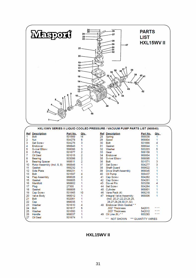
HXL15WV II

32
HXL15WF II

33
HXL15V II

34
HXL15F II

35
HXL20WV II

36
HXL400WV

37
MASPORT PUMP REPLACEMENT PARTS KITS Complete Replacement Parts Kits
Part # Model Shipping Weight - Lbs
Description: Replacement Parts Kit
14619 H4V, HXL4V 6 14603 H5V, HXL5V 6 14623 HXL5WF 6 14604 H75V, HXL75V, HXL75V II 6 14605 H75WV, HXL75WV, HXL75WV II, HXL75WV II 6 14608 HXL15V 8 14606 H15WV, HXL15WV, HXL15WV II 8 14625 HXL20WV II 9 14630 HXL400WV II 12 Kit Includes: Vanes, Bearings, End Thrust Nut O-Rings, Oil Seals, Bearing Spacers, Endcover Shim Gaskets, Valve Gasket(s), Flange Gasket(s), Flap Asssembly(s), Endcover O- Rings and Installation Manual Replacement Parts Kits Less Bearings, Bearing Spacers, and Flap Assemblies
Part # Model Shipping Weight - Lbs
Description: Kit Less Bearings, Flap Assy
14650 H5V, HXL5V 5 14651 H75V, HXL75V 5 14652 H75WV, HXL75WV 5 14653 H15WV, HXL15WV 7 14654 HXL15V 7 14655 H4V, HXL4V 5 14656 HXL20WV II 8 14657 HXL400WV II 10 Kit Includes: Vanes, End Thrust Nut O-Rings, Oil Seals, Endcover Shim Gaskets, Valve Gasket(s), Flange Gasket(s), Endcover O-Rings and Installation Manual
MASPORT GENUINE VANE PACKS Part # Model Dimensions Vanes per
Pack Shipping
Weight-Lbs Description: Vane Pack
975536 H2,HXL2 4 1/16" x 1 7/8" 4 1 968236 H3,HXL3 6" x 1 7/8" 4 1 975393 H4,HXL4 11" x 2 9/16" 4 2 975539 H75,HXL75 8 9/16" x 2 5/8" 4 2 968218 H15,HXL15 12 7/8" x 2 9/16" 4 3 968916 H20,HXL20 13 5/8" x 3" 4 3 968918 HXL400 13 5/8" x 3" 6 4
GENUINE MASPORT PUMP SPARES KITS AND PACKS

38
LIST OF OIL TYPES
MASPORT VACUUM PUMP OIL IS THE ONLY RECOMMENDED OIL FOR MASPORT PUMPS
MASPORT VACUUM PUMP OIL Masport Incorporated – Lincoln, NE 800-228-4510
One Gallon Case of 6 Gallons Summer Blend 13996 13997
Winter Blend 13998 13999 OILS OR FLUIDS THAT SHOULD NOT BE USED IN MASPORT VACUUM PUMPS
TRANSMISSION FLUID AUTOMOTIVE MOTOR OIL POWER STEERING FLUID USED OIL VEGETABLE OIL BRAKE FLUID HYDRAULIC FLUID GEAR OIL SCENTED OIL
SUBSTITUTE OILS SUITABLE FOR TEMPORARY USE IN
MASPORT PRESSURE / VACUUM PUMPS SHELL TURBO T OIL 32, 68, 100 Shell Oil Company – Houston, TX 800-231-6950 MONOLEC COMPRESSOR OIL* Lubrication Engineers – Fort Worth, TX 817-834-6321 MOBIL SHC 525 (Synthesized Hydrocarbon) Mobil Oil Company – Fairfax, VA 800-662-4525 ANDEROL 497 Anderol Inc – East Hanover, NJ 888-263-3765 CHEVRON GST 32, 68 ChevronTexaco Corporation – San Ramon, CA 800-822-5823 PENNZBELL TO OIL 32, 46, 68 Pennzoil Oil Company – Houston, TX 800-332-6457 REGAL OIL R & O 32, 68 ChevronTexaco Corporation – San Ramon, CA 800-822-5823
* Monolec Compressor Oil is colored red and should not be confused with transmission fluid. These oils have been approved for use in Masport Pressure / Vacuum Pumps. Use of these oils will extend the life of the vacuum pump and insure proper performance and lubrication.
NOTE: Oils numbered 32 & 46 are for winter use**. Oils numbered 68 & 100 are for summer use. **Check pour point to determine minimum temperature.
For more information call:
MASPORT INCORPORATED 6140 McCormick Drive Lincoln, Nebraska 68507
Phone: 402-466-8428 FAX: 402-466-8355 Toll Free 800-228-4510 www.masportpump.com