air texture gun air...• 1 x air texture gun • 1 x plastic hopper • 1 x 45-degree elbow...
TRANSCRIPT

OPERATING & MAINTENANCEINSTRUCTIONS
GC0410
AIR TEXTURE GUNModel No CTG8
Part No 5091120

2
INTRODUCTION
Thank you for purchasing this CLARKE product.
Before attempting to operate the Air Texture Gun, it is essential that you readthis manual thoroughly and carefully follow all instructions given. In doing soyou will ensure the safety of yourself and that of others around you, and youcan also look forward to the product giving you long and satisfactory service.
GUARANTEE
This CLARKE product is guaranteed against faulty manufacture for a period of12 months from the date of purchase. Please keep your receipt as proof ofpurchase. Upon receipt, any damage or deficiency should be reported toyour CLARKE dealer immediately.
This guarantee is invalid if the product is found to have been abused ortampered with in any way, or not used for its intended purpose. Faulty goodsshould be returned to their place of purchase, no product can be returnedto us without prior permission.
This guarantee does not effect your statutory rights.
ENVIRONMENTAL PROTECTION
Do not dispose of this product with general household waste. All tools,accessories and packaging should be sorted, taken to a recyclingcentre and disposed of appropriately.
TECHNICAL SPECIFICATION
Please note that the details and specifications contained herein, are correct at thetime of going to print. However, CLARKE International reserve the right to changespecifications at any time without prior notice.
erutaeF noitacificepS
thgieW gk5.1
yticapaCreppoH )lag57.1(ertil59.7
seziSelzzoN mm6.3&mm5.3,mm7.2,mm5.1
noitpmusnoCriA mfc52-6

3
GENERAL SAFETY PRECAUTIONS
FOR YOUR PERSONAL SAFETY AND THAT OF OTHERS AROUND YOU.FOLLOW THESE SAFETY INSTRUCTIONS CAREFULLY.
NOTE : Products used in this spray gun may be covered by COSHHRegulations.
1. ALWAYS check the manufacturers data sheets on the products beingsprayed for any particular hazards, and follow the manufacturersinstructions. Take particular care if spraying isocyanate paints.
2. ALWAYS wear a suitable approved breathing mask when spraying, toprotect against inhalation of paint spray or fumes. An air feed mask maybe required when spraying some types of paint. If in doubt, check with thepaint manufacturer.
3. ALWAYS make sure there is adequate ventilation. Do not spray in confinedor enclosed areas.
4. ALWAYS disconnect the spray gun from the air supply when it is not in use,and before any disassembly.
5. ALWAYS keep the spray nozzle in place when spraying.
6. ALWAYS thoroughly clean the spray gun after use. See ‘Maintenance’onpage 8.
7. NEVER spray paint towards people or animals. In the case of injury, seekexpert medical advice immediately.
8. NEVER smoke while spraying or preparing solvent based paints, or spraynear a naked flame, heat source or electrical sparks. Solvent-based paintsare flammable.
9. ALWAYS store this product in a dry, secure place out of reach of children.
10. NEVER carry out any alterations or modifications to this product.
11. NEVER use this product if it is defective/operating abnormally.
12. NEVER attempt any repairs yourself. If you have a problem with thisproduct contact your local CLARKE dealer.
Your CLARKE product has been designed to give long and trouble freeservice. If, however, having followed the instructions in this booklet carefully,you encounter problems, take the unit to your local CLARKE dealer.
Please keep these instructions in a safe place for future reference.
4
INTRODUCTION
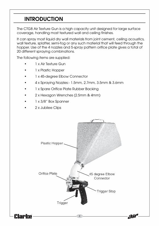
The CTG8 Air Texture Gun is a high capacity unit designed for large surfacecoverage, handling most textured wall and ceiling finishes.
It can spray most liquid dry wall materials from joint cement, ceiling acoustics,wall texture, splatter, semi-fog or any such material that will feed through thehopper. Use of the 4 nozzles and 5-spray pattern orifice plate gives a total of20 different spraying combinations.
The following items are supplied:
• 1 x Air Texture Gun
• 1 x Plastic Hopper
• 1 x 45-degree Elbow Connector
• 4 x Spraying Nozzles:- 1.5mm, 2.7mm, 3.5mm & 3.6mm
• 1 x Spare Orifice Plate Rubber Backing
• 2 x Hexagon Wrenches (2.5mm & 4mm)
• 1 x 3/8” Box Spanner
• 2 x Jubilee Clips
5
PREPARATION FOR USE
WARNING: COMPRESSED AIR CAN BE DANGEROUS. ENSURE THAT YOUARE THOROUGHLY FAMILIAR WITH ALL PRECAUTIONS RELATING TO THEUSE OF COMPRESSORS AND COMPRESSED AIR SUPPLY.
Your air texture gun comes complete with 4 different size nozzles. The largerthe nozzle, the more compressed air is required and a minimum of 6.5 cfm willbe required from the compressor if the largest nozzle is being used.
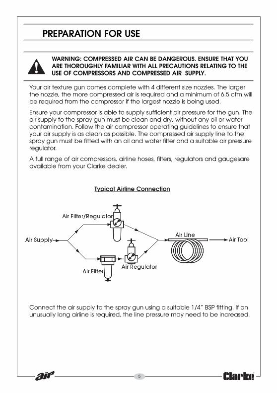
Ensure your compressor is able to supply sufficient air pressure for the gun. Theair supply to the spray gun must be clean and dry, without any oil or watercontamination. Follow the air compressor operating guidelines to ensure thatyour air supply is as clean as possible. The compressed air supply line to thespray gun must be fitted with an oil and water filter and a suitable air pressureregulator.
A full range of air compressors, airline hoses, filters, regulators and gaugesareavailable from your Clarke dealer.
Connect the air supply to the spray gun using a suitable 1/4” BSP fitting. If anunusually long airline is required, the line pressure may need to be increased.
Typical Airline Connection

6
OPERATION
Assemble the texture spray gun as follows. The numbers in brackets refer tothe Parts List & Parts Diagram on pages 10/11.
1. With the jubilee clip (5) around the hopper base loosened off, fit thehopper (1) to the gun body, pushing the hopper onto body neck, (thehandle on hopper should be in line with the gun body). Tighten the clampsufficiently to prevent the hopper from moving.
2. When spraying upwards towards a ceiling, the 45deg elbow (6) should beadjusted to keep the hopper in an upright position, securing it with boththe jubilee clips.
INSTALLING THE NOZZLE1. To select a nozzle, prize off the
retaining cap (27) and chooseyour nozzle from the selectionstored inside the body of thegun.
2. Depending on the viscosity ofthe material to be sprayed, fitthe appropriate nozzle, (e.g,1.5mm and 2.7mm nozzles formedium viscosity materials and3.5 mm nozzle for high viscositymaterials), as follows.
3. Loosen the securing block (34),and remove the orifice plate (31). Unscrew the nozzle (18) currently fittedand screw the chosen nozzle onto the end of the inlet tube (30), takingcare not to lose the white rubber seal ring (42) from inside the nozzle.Tighten the nozzle with the box spanner (28) stored inside the handle.Replace the orifice plate and securing block.
NOTE: The largest (3.6 mm) nozzle cannot be tightened with the box spanner.Instead, the 4mm Allen key must be used.
CONNECTING AND FILLING1. Connect the air hose using an appropriate connector as necessary. An air
regulator can be fitted to the gun first, which can be used to control thedroplet size produced by the spray gun, turning clockwise to restrict the airflow. (The greater the flow, the smaller the droplet).
2. Turn the air supply on and check the functionality of the gun by squeezingthe trigger before filling with paint etc.
3. Turn air off and fill hopper with material to be sprayed, (1.75 gallons max)Always mix the paint to the correct viscosity for spraying according to the
7
manufacturer’s instructions. (DO NOT OVERFILL - the more paint theheavier the spray gun).
4. Hold the gun approximately 12” from wall to be covered, supporting thegun using the handle on the hopper.
5. Gently squeeze the trigger until resistance is felt whilst moving the gunfrom side to side. Check the coverage and change the orifice/nozzle sizeif necessary, or adjust the air flow regulator adjustment, if fitted.
6. Before using the gun, practice getting the feel of the trigger with thechosen settings.
The trigger stop can be used in order to select the same setting for repeatoperations. Wait until the trigger is in the desired position before tighteningthe wingnut (8) to limit trigger movement.
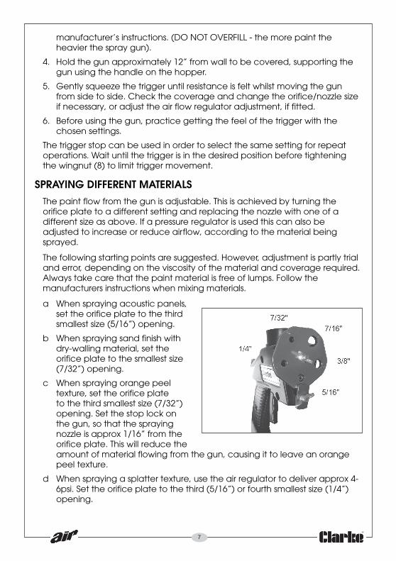
SPRAYING DIFFERENT MATERIALSThe paint flow from the gun is adjustable. This is achieved by turning theorifice plate to a different setting and replacing the nozzle with one of adifferent size as above. If a pressure regulator is used this can also beadjusted to increase or reduce airflow, according to the material beingsprayed.
The following starting points are suggested. However, adjustment is partly trialand error, depending on the viscosity of the material and coverage required.Always take care that the paint material is free of lumps. Follow themanufacturers instructions when mixing materials.
a When spraying acoustic panels,set the orifice plate to the thirdsmallest size (5/16”) opening.
b When spraying sand finish withdry-walling material, set theorifice plate to the smallest size(7/32”) opening.
c When spraying orange peeltexture, set the orifice plateto the third smallest size (7/32”)opening. Set the stop lock onthe gun, so that the sprayingnozzle is approx 1/16” from theorifice plate. This will reduce theamount of material flowing from the gun, causing it to leave an orangepeel texture.
d When spraying a splatter texture, use the air regulator to deliver approx 4-6psi. Set the orifice plate to the third (5/16”) or fourth smallest size (1/4”)opening.

8
e The air texture gun can also spray glitter if the material and gun are bothkept dry. Approx 15 psi is recommended to apply glitter to panelling and25-30 psi to cement and stucco surfaces. The glitter should be sprayed onwhile the underlying material is still tacky enough to receive it and to forman effective bond.
MAINTENANCE
WARNING: DISCONNECT THE SPRAY GUN FROM THE AIR SUPPLY, ANDRELIEVE ANY PRESSURE IN THE GUN AND HOSE, BEFORE ANYDISASSEMBLY.
After use, always clean the gun and hopper with clean water ready for nextuse. It is essential that the spray gun is kept clean. Dried paint in the nozzleassembly or airways will stop the gun from working correctly.
For the gun to perform at it’s best the moving parts should be lubricatedregularly using a light machine oil. Use a couple of drops of oil inside the airinlet (35) to lubricate the inlet tube (30) and repeat this through the triggerstop slot and with the gun upside down, pull back the trigger and apply oil tothe inlet tube.
Remove all excess oil with a cleancloth.
When re-assembling the gun aftercleaning, adjust the trigger on theinlet tube, so that the nozzleprotrudes 1/6” past the nose piecewhen the trigger is in the fullyforward position, or it will not seatproperly. (The small hexagonalwrench is provided for thispurpose). Check that the front ofthe orifice plate bears against thefront of the gun to avoid any leaksat this point.
If leaks are observed around the gun body, replace the gaskets shown onpages 10 & 11. If this is not successful, use sealant between the two halves ofthe gun body to prevent leakage.
CAUTION: never use silicon based lubricants as this may cause damage to thepaint finish.
Do not overtighten components, and be careful not to cross thread any partson re-assembly.

9
Please be aware that certain parts of this spray gun will wear, requiringreplacement and that these parts may not be covered by your guarantee.The wear on certain parts depends on the abrasive nature of the materialsbeing sprayed. More abrasive materials such as latex paint (emulsions) willcause these parts to wear much faster.
Use only Clarke replacement parts, available from your nearest ClarkeInternational dealer.

10
IMPORTANT: The use of parts other than genuine CLARKE replacement partsmay result in safety hazards, decreased performance, and will invalidate yourwarranty.
oN noitpircseD oN noitpircseD
1 reppoH 12 hsuBtroppuStelnIriA
2 eldnaH 22 )mm21(wercsdaehtekcoS
3 wercS 32 )mm51(wercsdaehtekcoS
4 rehsaW 42 )mm52(wercsdaehtekcoS
5 pilCeellibuJ 52 reveLelttorhT
6 woblEged54 62 wercSteSmm5.2
7 tungniWgniniateR 72 paCgniniateR
8 tungniWgnitsujdA 82 rennapSxoB
9 )tfel(ydoBnuG 92 tennoBrebbuR
01 )thgir(ydoBnuG 03 ebuTtelnI
11 tloB 13 etalPecifirOtnorF
21 rehsaW 23 gnikcaBrebbuRevisehdA
31 )a(teksaG 33 )mm83(gnirpSlioC
41 )b(teksaG 43 kcolBgniruceS
51 )c(teksaG 53 telnIriA
61 gniR-O 63 tloBnogaxeH
71 gniRretuO 73 )mm5.2(hcnerWlanogaxeH
a81 )mm7.2(elzzoN 83 )mm4(hcnerWlanogaxeH
b81 )mm5.1(elzzoN 93 )d/imm7(pilcriC
c81 )mm5.3(elzzoN 04 )mm81(gnirpSlioC
91 )ezisobmuJmm6.3(elzzoN 14 rehsaW
02 gniR-O 24 gniRlaeSrebbuRetihW
PARTS LIST

11
PARTS DIAGRAM
PARTS LIST
