air-to-water heat pump chillers -screw type - hitachi
TRANSCRIPT

AIR-TO-WATERHEAT PUMP CHILLERS-SCREW TYPE-
Installation, Operation and Maintenance Instructions.Design Information
Technical Catalog
RHUE40AG2-240AG2 (R407C)Cooling Capacity 106 kW - 585 kWHeating Capacity 110 kW - 556 kW


0
TABLE OF CONTENTS
1. IMPORTANT NOTICE................................................................................................................. 1
2. FEATURES AND BENEFITS...................................................................................................... 12.1. New chiller picture.................................................................................................................................12.2. Compressor ..........................................................................................................................................22.3. Control ..................................................................................................................................................32.4. New fan motor.......................................................................................................................................42.5. New electronic expansion valve............................................................................................................4
3. OPERATION INSTRUCTIONS ................................................................................................... 53.1. HITACHI Air-Cooled Water Chillers ......................................................................................................5
4. COMPONENTS OF CHILLER .................................................................................................... 64.1. Structure drawing..................................................................................................................................6
5. PREPARATION INITIAL CHECK ............................................................................................... 75.1. Initial check ...........................................................................................................................................75.2. Placing the unit .....................................................................................................................................85.3. Centre of gravity....................................................................................................................................95.4. Service space and foundation...............................................................................................................105.5. Transportation.......................................................................................................................................12
6. INSTALLATION .......................................................................................................................... 136.1. Electrical wiring .....................................................................................................................................136.2. Water piping..........................................................................................................................................156.3. Common water piping (option) ..............................................................................................................166.4. Minimum internal system water volume ................................................................................................176.5. Water control.........................................................................................................................................176.6. BMS connection....................................................................................................................................186.7. CSC-5S.................................................................................................................................................256.8. Installation final check...........................................................................................................................28
7. TEST RUNNING.......................................................................................................................... 297.1. Preparation ...........................................................................................................................................297.2. Test running..........................................................................................................................................297.3. Instructions after test running................................................................................................................29
8. CONTROLLER ADJUSTMENT .................................................................................................. 308.1. Control system......................................................................................................................................318.2. Controller adjustment............................................................................................................................31
9. SELF-INSPECTION FUNCTIONS .............................................................................................. 349.1. Alarm indication ....................................................................................................................................349.2. Normal indication ..................................................................................................................................359.3. Function for indication of operation condition........................................................................................36
10. CONTROL SYSTEM ................................................................................................................. 43
11. MAINTENANCE ........................................................................................................................ 4611.1. Components........................................................................................................................................4611.2. Lubrication ..........................................................................................................................................4611.3. Deposit................................................................................................................................................4611.4. Cleaning method.................................................................................................................................4711.5. Winter shutdown .................................................................................................................................4911.6. Spring start-up ....................................................................................................................................4911.7. Part replacement.................................................................................................................................4911.8. Refrigeration cycle ..............................................................................................................................4911.9. Refrigerant cycle diagram Of Hitachi Air-Cooled Water Chiller
(RHUE 40, 50, 60, 70, 100, 120, 140, 180, 210 AG2).........................................................................5011.10.Refrigerant Cycle Diagram Of Hitachi Air-to-water Heat Pump
(RHUE 80, 160, 240 AG2) With Economizer. .....................................................................................5111.11. Compressor removal.........................................................................................................................5211.12. Safety and protection control ............................................................................................................5311.13. Normal operating pressure................................................................................................................5511.14. Test running and maintenance record ..............................................................................................5611.15. Daily operating records .....................................................................................................................5711.16. Servicing for R407C refrigerant system ............................................................................................58

0
TABLE OF CONTENTS (cont.)
12. TROUBLESHOOTING ..............................................................................................................58
13. GENERAL SPECIFICATIONS..................................................................................................6113.1. General data.......................................................................................................................................61
14. DRAWINGS...............................................................................................................................6514.1. Dimensional drawing ..........................................................................................................................6514.2. Wiring diagram....................................................................................................................................71
15. MODEL SELECTION ................................................................................................................8015.1. Selection example ..............................................................................................................................8015.2. Performance table (Cooling operation) ...............................................................................................8115.3. Performance table (Heating operation)...............................................................................................8415.3. Electrical data .....................................................................................................................................8715.4. Sound data .........................................................................................................................................88
16. APPLICATION DATA ...............................................................................................................8916.1. Working range ....................................................................................................................................8916.2. Part load performance ........................................................................................................................9016.3. Ethylene glycol application .................................................................................................................90
17. COMPONENTS DATA ..............................................................................................................9217.1. Compressor ........................................................................................................................................9217.2. Condenser and condenser fan ...........................................................................................................9217.3. Water cooler .......................................................................................................................................93

IMPORTANT NOTICE 1/1
1. IMPORTANT NOTICE HITACHI pursues a policy of continuing improvementin design and performance of Products. The right istherefore reserved to vary specifications without notice. HITACHI cannot anticipate every possiblecircumstance that might involve a potential hazard. No part of this manual may be reproduced withoutwritten permission. Signal words (DANGER, WARNING and CAUTION)are used to identify levels of hazard seriousness.Definitions for identifying hazard levels are providedbelow with their respective signal words.
DANGER:Immediate hazards which WILL result in severepersonal injury or death.
WARNING:Hazards or unsafe practices which COULD result insevere personal injury or death.
CAUTION:Hazards or unsafe practices which COULD result inminor personal injury or product or property damage.
NOTE:Useful information for operation and/or maintenance.
If you have any questions, contact your contractor ordealer of HITACHI. This instruction gives a common description andinformation for this air-to-water heat pump Chillerwhich you operate as well as for other models. This air-to-water heat pump Chiller has been designedfor the following temperatures. Operate the air-to-waterheat pump Chiller within this range.Working RangeFor Cooling Operation °C
Maximum MinimumAmbientTemperature 46 -15
Chilled WaterOutlet Temperature 15 5
Working RangeFor Heating Operation °C
Maximum MinimumAmbientTemperature
-9.5 (DB)-10 (WB)
21 (DB)15.5 (WB)
Hot WaterOutlet Temperature 55 35
This instructions should be considered as a permanentpart of the air-to-water heat pump Chiller equipmentand should remain with the air-to-water heat pumpChiller equipment.
2. FEATURES AND BENEFITS
2.1. NEW CHILLER PICTURE
HITACHI is a world leader in technology and with continual research and product development, now offer a screw typeAir-to-water Heat Pump Chillers. A wide range of capacity are available from 106 KW to 585 KW for cooling operation, andfrom 110 KW to 556 KW for heating operation.

2/2 FEATURES AND BENEFITS
2.2. COMPRESSOR
THE SAMURAI RANGEINCORPORATES THE LATESTDEVELOPMENT OF HITACHI´SSCREW COMPRESSORTECHNOLOGY FOR THE NEWMILLENNIUM.
Highly Reliable HITACHI Two-PoleMotor
Built-in Oil Separator (Cyclone oilseparator)
Oil Sight Glass
Oil Heater
High precision Twin Screw Rotors
Suction Filter
TWIN SCREW COMPRESSORBy having so few moving parts, it has become highly reliablewith very low noise level and low vibration
PRINCIPLE OF COMPRESSION
CONTINUOUS CAPACITY CONTROLHITACHI´s Continuous Capacity Control system usesadvanced electronic controls to position the infinitelyvariable slide valve within each compressor.This modulation allows exact load control and accuratechilled water temperature without the need forexpensive inverters.
Reciprocating Screw
AM
PLI
TUD
E (µ
m)
Time (second)
-LOW VIBRATION-
Discharge Port
Suction Port
Cooling load = continuos capacity control
CO
OLI
NG
LO
AD
%
Stepcontrol
TIME (Hour)
(In the case of cooling operation)

FEATURES AND BENEFITS 2/3
Energy Saving
Thanks to Continuous Capacity Control, 15~20% energysaving is possible compared with current step controlsystems due to the following:
The cooling load can be more closely matched Continuous Capacity Control takes advantage of highefficiency part load performance. Frequent compressor starts and stops are eliminated.
-PART LOAD PERFORMANCE-
2.3. CONTROL Many Functions
Newly developed Control Board has many functions shownbelow as standard.
Current limiter Forced compressor load control 2 different temperature setting Various fan control mode Memory for data in alarm Automatic restart after power failure Output signal for free cooling application
etc...
Precise Temperature ControlCombination of "Continuous Capacity ControlCompressor" and "HITACHI´s uniqueelectronic controls" enable the Chiller tocontrol outlet water temperature precisely,independent of cooling load.This control benefits not only air-conditioningbut also industrial process use.
-CONTINUOUS CAPACITY CONTROL-
-CONVENTIONAL STEP CONTROL-
MO
TOR
INP
UT
(%)
COOLING CAPACITY (%)
Continuous CapacityControl
StartOutlet WaterTemperature
Load Up 2
Load Up 1(Quick cooling)
Neutral =2°C Standard(Minimum 0.5°C)Load Down
TIME
WA
TER
TE
MP
ER
ATU
RE
WA
TER
TE
MP
ER
ATU
RE Restart
1st step
Final step
OutletTemperature
TemperatureBand 7°C(normally)

2/4 FEATURES AND BENEFITS
2.4. NEW FAN MOTOR
DC Fan Motor with Outstanding EfficiencyThe DC fan motor greatly improves efficiency compared toconventional products using an AC motor. Also, air blastsare reduced by controlling the rotation speed of the fan.
PWM (pulse width modulation) concept of speedcontrolThe switching element (a power MOSFET) switches backand forth at a frequency of several tens of kHz. Thiscontrols the ON//OFF duty rate per cycle and thus changesthe voltage applied to the fan motor to control the rotationspeed.
Low Sound
Hitachi uses high technology toachieve the lowest sound. Thenew two bladed propeller,rather then four bladed,achieves a reduction of noiselevel, increases air flowvolume, and at the same timeprovides an important reductionof motor power input
2.5. NEW ELECTRONIC EXPANSION VALVE
This unit are equipped with an electronic expansion valveto provide sophisticated control under any temperaturecondition.
The electronic expansion valve provides reduced electricalpower consumption compared to the classical system.
Mot
or E
ffici
ency
(%)
Revolutions per Min. (rpm)
AC Motor
DC Motor
Efficiency increased by 40%.(motor input halved)

OPERATION INSTRUCTIONS 3/5
3. OPERATION INSTRUCTIONS
3.1. HITACHI AIR-TO-WATER HEAT PUMP CHILLERS
To Start the Unit.1. Open the water inlet and outlet valves.2. After assuring that all control switches have been cut
OFF, and the "LOCAL/REMOTE" switch on the printedcircuit board is in the "REMOTE" position, turn ON thepower switch.
3. Confirm that phases R, S and T are correctly connected.The correct phase connection can be checked by aphase sequence indicator. If not correctly connected, thecompressor does not start due to activation of a reversalphase protection device. Cut the main switch andinterchange two of three terminals, R, S and T at themain power source terminals.
4. Set the changeover switch to “Cool” or “Heat”5. Fully open the liquid line stop valves.6. Operate the chilled (hot) water pump.7. Depress the "*ON" push button switch.
( * Field-Supplied )8. Set the thermostat at the desired temperature
To Stop the Unit1. Depress the "*OFF" push button switch.
( * Field –Supplied)2. Switch OFF the main power source when the unit is shut
down for a long period of time.
Pilot LampThe red LED indicates the normal operation.When the orange LED is activated, any one of the safetydevices may be functioning.Please contact your service shop, if this condition isdetected.
Daily Checking1. Check the power supply to ensure that it is proper.2. Check for abnormal sounds and vibrations.3. Check the unit amperage.4. Check the operating pressure.
Troubleshooting
Unit Does Not Start1. Is the main switch ON?2. Is the main fuse OK?3. Is the chilled (hot) water running?4. Are the thermostats calling for the cooling (heating)
operation?
Poor Cooling (Heating) Operation1. Is there sufficient Air supplied to the air side heat
exchanger?2. Is the setting temperature correct?3. Are the operating pressures normal?4. Is there sufficient water running through the water side
heat exchanger?
Maintenance1. Remove any obstacles to air side heat exchanger
Airflow, and clean the air side heat exchanger.2. Clean the unit with a cleaner.3. Clean the water side heat exchanger. (It is
recommended that a specialist will be contacted for thistype of work.)
DANGER:Switch OFF main interruptor (M.I) for any work insideElectrical Box.

4/6 COMPONENTS OF CHILLER
4. COMPONENTS OF CHILLER
4.1. STRUCTURE DRAWING
HITACHI Air-to-water heat pump Chiller (Example of 2 Compressors Chiller)
N° Name N° Name1 Compressor 11 Liquid Line Stop Valve2 Water Side Heat Exchanger 12 Biflow Drier3 Air Side Heat Exchanger 13 Liquid Sight Glass4 Electrical Box 14 Solenoid Valve (only for 80, 160, 240 HP)5 Power Wiring Supply 15 Economizer (only for 80, 160, 240 HP)6 Fan 16 High Pressure Switch7 Check Valve 17 4-Way Valve8 Oil Sight Glass 18 Accumulator9 Operation Switch 19 Liquid Tank
10 Electronic Expansion Valve
Air Inlet
Air Outlet Air Outlet
Air Inlet AirInlet
Water Inlet
WaterOutlet
N°1 CYCLE N°2 CYCLE
Air Outlet
Detail of LPIPE structure.
Remote/ Local ChangeoverSwitch is Rear Side.
Air Outlet Air Outlet

PREPARATION INITIAL CHECK 5/7
5. PREPARATION INITIAL CHECK
5.1. INITIAL CHECK
Required MaterialsMeasure and Architectural Information RegardingInstallation Location
Installation LocationConfirm that the final installation location is provided withconvenient piping and wiring work. Strong water runoffshould be avoided.This unit must be installed in places not accessible to thegeneral public. Install the unit on a roof or in an area wherepeople, except service engineer, can not touch the unit.
Installation Space
Check for obstacles which restrict condenser Air flow orhamper maintenance work in the space specified in Fig. 1.
Foundation
Check to ensure that the foundation is flat, level andsufficiently strong, taking into account the maximumfoundation gradient (Fig. 2) and the unit weight balance.Confirm elevation provision for the unit on a solid base withan iron frame or concrete curbs shown in chapter 5.4.
In order to obtain proper clearance beneath the unit foreither rooftop or on-the-ground installation, wherefoundation bolts should be sunk into concrete. Additionally,for on-the ground installation, provide a gravel or concretespace around the condenser Air intake; in order to avoidAirflow obstruction due to grass or other vegetation.
Unit
Check to ensure that the unit has been transported withoutdamage. File a damage claim with the transportationcompanies if mishandling due to transportation companynegligence is suspected.
Transportation
Secure the route to the final installation location byconfirming the dimensions, (Refer to the "Unit GeneralData" in Catalogue).

5/8 PREPARATION INITIAL CHECK
5.2. PLACING THE UNIT
DANGER:If leakage is detected, stop the unit and contact theinstaller or service shop. Do not use a naked fire nearthe refrigerant gas. If a naked fire is utilised near therefrigerant gas, refrigerant is turned into a harmfulphosgene compound.
WARNING:This unit is operated with refrigerant R407C, which isnon-flammable and non-poisonous. However,refrigerant itself is heavier than the atmosphere sothat a floor is covered with refrigerant gas ifrefrigerant is leaked. Therefore, keep good ventilationto avoid choke during servicing.
CAUTION:Check to ensure that valves are correctly opened. Ifnot opened, serious damage will occur to thecompressor due to an abnormal high pressure.This unit controls air flow for condenser during lowambient temperature.Due to this control, avoid the strong wind hits the unitdirectly. In such a case, put buffer plate around theunit.
Tools and InstrumentsPincers, Wrenches, Facilities to Transport and Place TheUnit.
TransportationTransport the unit as close to the final installation locationas practical before unpacking is accomplished. Provideadequate facilities to place the unit on the foundation, withsufficient consideration given to those individualsperforming the installation.
UnpackingFollow the instructions marked on the packing.
Fig.1. Operation Space
NOTE:The height of the wall shall be smaller than that of theunit cabinet.When the unit is installed at a location where the unit isencircled with walls and obstruction of free Air circulationis suspected, construction with HITACHI regarding theoperation space is recommended.
Maximum Foundation GradientThe unit should be installed in an upright position within thegradient shown in Fig.2.
Fig.2. Maximum Foundation Gradient
15 mm
30 mm
3000 mmOverhead AirClearance
h1 ≤ h2
h1
h2

PREPARATION INITIAL CHECK 5/9
5.3. CENTRE OF GRAVITY
Centre of Gravity
Fig.3. Centre of Gravity
RHUE 40, 50, 60, 70, 80AG2 RHUE 100, 120, 140, 160AG2
RHUE 180, 210, 240AG2
RHUE - AG2Model 40 50 60 70 80 100 120 140 160 180 210 240
Location Weight Distribution (kg)
123456789101112
336336447447
350350460460
364364484484
406406546546
424424564564
331331331331440440440440
356356356356468468468468
399399399399531531531531
413413413413544544544544
349349349349349349459459459459459459
394394394394394394525525525525525525
412412412412412412542542542542542542
Operating Weight (kg)
(kg) 1565 1620 1695 1905 1975 3085 3295 3720 3830 4850 5515 5725
Location of Center of Gravity (mm)
DimensionA
DimensionB
1170
815
1165
820
1170
815
1340
810
1350
815
2095
815
2005
820
2470
815
2480
820
2930
820
3690
815
3700
820
Centre of Gravity
Control Panel

5/10 PREPARATION INITIAL CHECK
5.4. SERVICE SPACE AND FOUNDATION
RHUE 40, 50, 60 AG2 RHUE 70, 80 AG2
RHUE 100, 120 AG2
RHUE 140, 160 AG2
(Mounting Holes)
Bottom Frame
Vibration-proofRubber mat
(4 positions)
(Mounting Holes)
Bottom Frame
Vibration-proofRubber mat
(4 positions)
(Mounting Holes)
Bottom Frame
Bottom Frame
Vibration-proofRubber mat
(8 positions)
(Mounting Holes)
Vibration-proofRubber mat
(8 positions)

PREPARATION INITIAL CHECK 5/11
RHUE 180 AG2
RHUE 210, 240 AG2
DETAIL OF FUNDATION
Bottom Frame
Foundation Bolt
Rubber Bush(OPTION)
Steel Plate
Concrete
Vibration-ProofRubber Mat
(1 mat per position)(OPTION)
Nut
Washer
Vibration-proofRubber mat(12 positions)
Bottom Frame
Vibration-proofRubber mat(12 positions)
Bottom Frame

5/12 PREPARATION INITIAL CHECK
5.5. TRANSPORTATION5.5.1. Transportation by RiggingHook wire cables and apply field-supplied spreader bars onthe top of the unit (see figure below) to prevent the unitpanels from damage due to cable scratches. The unitshould remain in an upright position even during rigging.The wire cable to rig the unit shall be three times strongerthan the unit weight. Check to ensure that the rigging boltsare tightly fixed to the unit. The rigging angle shall be lessthan 60° as shown. The weight of the unit is indicated onthe unit label.
DANGER:Do not stand below the unit when rigging.
CAUTION:Put clothes between wires and the unit to avoiddamages.
Rigging shall be performed by the instruction drawingattached to the unit.(Here the example of RHUE120AG2 is shown).
Electrical Box
Spreader Bar(Field Supplied)
Rigging Holes(4-∅28)
Lifting Bracket(Field Supplied)
Fig.3. Rigging the unit
5.5.2. Transportation by RollerWhen rolling the unit, put at least 7 equal-sized rollersunder the base frames. Each roller must carry both theouter frames, and must be suited to balance the unit (seethe centre of gravity in page 5/9).
Fig.4.Transportation by Roller.
5.5.3. DECLINING THE UNIT DURINGTRANSPORTATION.
WARNING:Do not decline the unit more than an angle of 15° asshown in the figure during transportation. If declinedmore than an angle of 15°, the unit may fall down.
Fig.5. Declining the unit.

INSTALLATION 6/13
6. INSTALLATION
6.1. ELECTRICAL WIRING Tools and Instruments
One Set of Wiring tools and Electrical Tester (Clamp Meter)
Schedule Check
DANGER:- Switch OFF main interruptor (M.I) for any work
inside Electrical Box.
WARNING:- Confirm that the field-selected electrical
components (main power switch, fuses, wires,conduit connections, wire terminals and others) areproperly selected according to the “Electrical Data“in this Technical Catalogue, and ensure that theycomply with national and local codes.
- It is recommended that the main power switch belocked in the “OFF“ position, to prevent againstaccidental supply of power during equipmentservicing.
- Check to ensure that an earthing wire is correctlyconnected to the unit. This wire protects from anelectric shock. Utilisation of an earth leakagebreaker is necessary.
Main Power Wiring ProceduresConfirm that electrical power is not being supplied to theinstallation location prior to any electrical installation work.1. Install the field-supplied main switch box(es) at a
properly selected location.2. Install conduit connectors in the hole for the power
wiring.3. Lead main power wires and the earthing wire through
the connector to the screw terminals for main power andearthing in the magnetic switch box. The neutral wiresfor 380V/50Hz and 415V/50Hz power supply should alsobe led through the connector.
4. Firmly connect the wires with wire terminals to unitscrew terminals R, S, T and N according to Fig. 6.
5. Connect the wires between the power source and thefield-supplied magnetic switches.
6. Consider that the main power source will not be leftturned OFF, easily, because it is necessary to energisethe oil heater even during unit stoppage.
Fg.6. Main Power Wiring.
N° Name1 Main Power/Terminal Board (R,S,T,N)2 Electrical Box3 Main Power Switch4 Main Power Wiring5 Earth Wiring
Control WiringConnect the interlock wiring and control wiring between theunit terminals and the magnetic switches for the waterpumps, according to Fig. 7 or the wiring label. The mainconnection to terminal N is required.

6/14 INSTALLATION
Fig.7. Control Circuit Wiring. NOTE:1. All the settings shall be performed before Power ON.2. Remote/Local Change over Switch on Operation
Switch shall be set to "Remote".3. Terminals 1~n55 are for AC220-240V,
Terminals A~D are for DC24VTerminals E~F are H-LINK (Low signal)
N° Name
1 Low voltage / Remote Control
2 Run / Stop Signal
3 Alarm Signal (DC24V)
4 In case of Remote Control operation this wire shall be removed
5 R Phase
6 Neutral
7 Alarm Lamp
8 Pump Interlock
9 Pump Operation
10 Remote Control Switch (RSW-A) (Option)
11 2nd. Setting Temperature
12 External Thermostat Operation
13 External Fan Operation
14 Only used for different water pressure switch orflow switch options
15 Force Compressor load operation
16 Caution lamp for fan operation
17 Free cooling output signal (Only cycle nº1), Valve
18 Setting of low voltage control
19 In case of individual indication without Remote Control Switch. (5 cycles)
20 Operation Mode
Customer WiringMODE(No use low voltage control) Dip Switch Setting
(DSW1 of Main PCB)
NORMALMODE(No Low Voltage Control)
2,3 Cycles3 Cycles
Force Compressor Load

INSTALLATION 6/15
6.2. WATER PIPING
When Piping Connections are performed:1. Connect all pipes as close as possible to the unit, so
that disconnection can be easily performed whenrequired.
2. Connect the Water Coolers in the same unit to the samecommon Water Piping.
3. It is recommended for the piping of the chilled water inletand outlet that flexible joints be utilised, so that vibrationwill not transmit.
4. Whenever permissible, sluice valves should be utilisedfor water piping, in order to minimise flow resistance andto maintain sufficient water flow.
5. Proper inspection should be performed to check forleaking parts inside and outside the system, bycompletely opening the chilled water inlet and outletvalves to the water side heat exchanger.Additionally, equip valves to the inlet and outlet piping.Equip an air purge cock on the inlet piping and a draincock on the outlet piping. The cock handle should beremoved so that the cock can not be opened undernormal circumstances. If this cock is opened duringoperation, trouble will occur due to water blow-off.
6. Sufficiently perform insulation to keep the chilled waterpiping cool and to prevent sweating of the piping.
7. Under the condition where the ambient temperature islow in winter, there is a case where equipment andpiping will become damaged during the shutdownperiods at night, because the water in the pump orpiping will be frozen. To prevent freezing of the water, itis effective to operate the pumps.HITACHI Chiller has the pump ON/OFF operationcontrol (see wiring diagram) water from piping.Additionally, in a case where measures such as waterdraining are difficult, utilise antifreeze mixture ofethylene glycol type or propylene glycol type.
8. The common water pipes (Inlet/Outlet) are fieldsupplied, only for RHUE 100∼240AG2.It is not necessary to install any sensor in these commonpipes for standard models.
Number of connections for models:
Models Water Inlet Water OutletRHUE 40, 50, 60, 70, 80AG2 1 1RHUE 100, 120, 140, 160AG2 2 2RHUE 180, 210, 240AG2 3 3
NOTE:Common Water Piping connecting each cooler isprepared as Option (Refer to page 6/16)
CAUTION:
This product is equipped with plate type heatexchanger. In the plate heat exchanger, water flowsthrough a narrow space between the plates.Therefore, there is a possibility that freezing mayoccur if foreign particles or dust are clogged. In orderto avoid this clogging, 20 mesh water strainer shallbe attached at the inlet of chilled water pipingnear the product. In case of punching metal typestrainer, mesh hole size shall be ∅ 1.5mm or less.Never use the salt type antifreeze mixture, because itpossesses strong corrosion characteristics, and waterequipment will be damaged.
Pressure Gauge
Strainer
Flexible Joint
Valve
CAUTION:In case of connecting some units to the same water piping, design the water piping so that the water distribution toeach unit is equal (refer to figure below) Imbalance of water distribution may cause a serious damage like a waterfreezing in the heat-exchanger.
Water Inlet
Water Outlet
Chiller
Water Pump
Heat Load Side
Chiller Unit

6/16 INSTALLATION
6.3. COMMON WATER PIPING (Option)
RHUE 100, 120, 140, 160, 180, 210, 240AG2
DIMENSIONS TABLE
Model Dim a b c d e Flange size Connecting pipediameter (mm)
RHUE100AG2
RHUE120AG23800 1385
RHUE140AG2
RHUE160AG25000
0
1685
335 300 4” 114.3
RHUE180AG2 5700 2220
RHUE210AG2
RHUE240AG27500 3420
1225 325 320 6” 168.3

INSTALLATION 6/17
6.4. MINIMUM INTERNAL SYSTEM WATER VOLUMETo ensure the cooling operation at least 5 minutes withoutinterruption, the internal chilled water volume in the pipingsystem should be greater than the minimum volume asshown below.
NOTE:Minimum internal system water volume written below isfor standard ON/OFF differential, minimum internalsystem water volume shall be increased by the setting ofdifferential.
MODEL RHUE AG2 40 50 60 70 80 100 120 140 160 180 210 240Minimum
Internal Water Volume m3 0.31 0.36 0.43 0.49 0.57 0.71 0.86 0.98 1.13 1.28 1.46 1.70
Internal Volume inWater Side Heat Exchanger Liter 15.1 16.7 21.5 23.9 23.9 33.4 43.0 47.8 47.8 64.5 71.7 71.7
6.5. WATER CONTROL
CAUTION:When industrial water is applied for chilled water andcondenser water, industrial water rarely causesdeposits of scales or other foreign substances onequipment. However, well water or river water may inmost cases contain suspended solid matter, organicmatter, and scales in great quantities. Therefore,such water should be subjected to filtration orsoftening treatment with chemicals before applicationas chilled water.
It is also necessary to analyse the quality of water bychecking pH, electrical conductivity, ammonia ioncontent, sulphur content, and others, and to utiliseindustrial water only if problem is encounteredthrough these checks.
The following is the recommended standard water quality.
Chilled Water System Tendency (1)
Item Circulating Water(20 °C Less than) Supply Water Corrosion Deposits of
ScalesStandard Quality pH (25 °C) 6.8 ~ 8.0 6.8 ~ 8.0Electrical Conductivity (mS/m) (25°C){µS/cm} (25 °C) (2)
Less than 40Less than 400
Less than 30Less than 300
Chlorine Ion (mg CI¯/I) Less than 50 Less than 50Sulphur Acid Ion (mg SO4
2¯/I) Less than 50 Less than 50The Amount of Acid Consumption (pH 4.8)(mg CaCO3/I)
Less than 50 Less than 50
Total Hardness (mg CaCO3 /I) Less than 70 Less than 70Calcium Hardness (mg CaCO3 /I) Less than 50 Less than 50Silica L (mg SIO2 /I) Less than 30 Less than 30Reference QualityTotal Iron (mg Fe/I) Less than 1.0 Less than 0.3
Total Copper (mg Cu/I) Less than 1.0 Less than 0.1Sulphur Ion (mg S2¯/I) It shall not be detected.Ammonium Ion (mg NH4
+/I) Less than 1.0 Less than 0.1Remaining Chlorine (mg CI/I) Less than 0.3 Less than 0.3Floating Carbonic Acid (mg CO2/I) Less than 4.0 Less than 4.0Index of Stability 6.8 ~ 8.0 -
NOTE:1. The mark " ” in the table means the factor
concerned with the tendency of corrosion or depositsof scales.
2. The value showed in "{}" are for reference onlyaccording to the former unit.

6/18 INSTALLATION
6.6. BMS CONNECTION
6.6.1. SYSTEMBMS connection is available by usingHARC70-CE1(OP), optional BMS interface unit.
One interface HARC70-CE1 can connect up to 4Chillers from a remote place using H-Link connection(Hitachi communications protocol).Protocol used by HARC70-CE1 (OP) is LonWorks. It canconnect only one Chiller.Physical channel connection with interface is FTT-10ª
6.6.2. SIGNAL
ON/OFF Chiller All HARC’SControl Operation
Outlet Water Setting All HARC’SON/OFF All HARC’SChilled Water Outlet Setting All HARC’SChilled Water Outlet Temperature All HARC’SChilled Water Inlet Temperature. All HARC’SAlarm Codes All HARC’SOperation Status All HARC’SDischarge Pressure 1,2 Only HARC OPSuction Pressure 1,2 Only HARC OPDischarge Temperature 1,2 Only HARC OPSuction Temperature 1,2 Only HARC OPCompressor Status (ON/OFF) 1,2 Only HARC OPOutlet Water Temp. 1 Only HARC OP
State Monitoring
Water Temp. In Evap. Backside 1 Only HARC OP
Chiller 1 Chiller 2 Chiller 3 Chiller 4
HARC70-CE1
Upper Monitoring Device
H-Link
LonWorks
Chiller 1
HARC70-CE1 OP
Upper Monitoring Device
H-Link
LonWorks

INSTALLATION 6/19
6.6.3. CAUTION ON USE HARC70-CE1 (OP)Please use it correctly according to the following"CAUTION ON USE.”
As for the following: “HARC” indicate “ HARC70-CE1” or“HARC70-CE1 OP” “Monitoring Device “ indicate “ upper connectingdevice for supervise “, and “Control Panel” indicate“Control panel of Chiller unit”. “SNVT” Indicate “Standard Network Variables Types”
1. Install HARC in a grounded metal box.2. Install a short circuit breaker in the power supply of
HARC.3. The transmission line between HARC and Chiller unit
should be “0.75mm2 twisted-Pair cable”. If it is notused, then it cannot communicate between HARCand Chiller unit, and it does not work properly.
4. After an abnormal transmitting occurs between HARCand Chiller unit, and Chiller unit stops, in the case ofoperation starting by the hand operation, then onceturn off Chiller unit’s power supply, and turn on thepower supply. If it isn’t carried out, then Chiller unitkeeps the condition of transmission alarm.
5. After an abnormal transmitting occurs between HARCand Chiller unit, and Chiller unit stops, in the case ofoperation starting by Monitoring Device, then transmitan operation order after you transmit a stop orderonce. If it isn’t carried out, it can't start.
6. After Chiller unit, under control by HARC, is stoppedby the control panel, and operation is done from theMonitoring Device, then transmit an operation orderafter you transmit a stop order once. If it isn’t carriedout, it can’t start.
7. Don't set the setting temperature to Chiller unit, undercontrol by HARC, by the control panel. If it is done,the setting temperature is changed. And, as for thesetting temperature, which changed in this case,transmit to Monitoring device.
8. After the setting temperature is changed byMonitoring Device, in the case of turned off Chillerunit’s power supply, set the setting temperature byMonitoring device again. If it isn’t carried out, then thesetting temperature becomes to the temperature bysetting control panel.
9. If power failure occurs in Chiller unit, under control byHARC, it may not revert to the condition before thepower failure. Try to detect that the operationcondition of Chiller unit changed, by the MonitoringDevice. If Chiller unit stopped due to the powerfailure, then transmit an operation order from theMonitoring Device after the power supply restoration.And, transmit the setting temperature, mode from theMonitoring device. If it isn’t carried out, and thenChiller unit is stopping, and the setting temperature,mode is the initialisation value by Chiller unit.
10.When SNVT, which is transmitted from HARC, isused by other control device, premise that there istwo minutes delay between the transmitting SNVTand the movement Chiller unit . If it isn’t premised,then a problem may occurs in the control system.
11.Don't interrupt the power supply of HARC when youuse SCPT in HARC. Even if it exceedsMaxSendTime, when SNVT is not transmitted fromHARC, and SNVT is transmitted below with thesetting value of MinSendTime, then transmit SCPTagain . If it isn’t carried out, SCPT value continuesmaintaining “0”.
12.If the setting of control panel change Remote toLocally, and set Remote again, then set the settingtemperature and mode from the Monitoring Deviceagain. If it does not set, then the setting temperatureand mode continue maintaining the initialisation valueby Chiller unit.
13.When the abnormal transmitting occurs between theMonitoring Device and HARC, then the condition ofthe Monitoring Device may not correspond with thecondition of HARC. Set MaxSendTime and try thatthe condition of the Monitoring Device correspondswith the condition of HARC in the interval ofMaxSendTime .
14.It can't be used with the except for “ stop signal ofinput terminal of Chiller unit “.
6.6.4. DIMENSIONAL DRAWING ANDSPECIFICATIONS OF HITACHI GATEWAY(MODEL HARC70-CE1/HARC70-CE1 0P)
Structural Drawing
Mounting Dimensions
Terminal CoverAfter Open
After OpenDown
ID number of NEURON CHIPOn Rear Side of Cover
Mounting by Screw
Mounting on DIN Rail
Center Line of DIN Rail

6/20 INSTALLATION
System Wiring
N° Description Wire Size
Power SupplyPower Wire AC 220/240V(Field Supplied)
2mm2 shielded
Connection Wiring Between Chiller Signal Wiring DC 5V(Field Supplied)
0.75mm2 twisted-pair cableMax. length 1000m
Ground Earth Wire(Field Supplied) -
Connection Wire Between LonWorks Signal Wire DC 5V(Field Supplied) -
Marking of Terminals
Mark Indication
POW Red: Power Supply (AC220/240V)
IRP Green: Lighted DuringTransmission Between LONWORKS
PAC Yellow: Lighted DuringTransmission Between Chiller
Wiring Procedures
Section Wiring Method Remark
1φ220-240V PowerSource ― HARC70-CE1(OP)
Pow
er L
ine
Earthing Wire
Upper System ― HARC70-CE1(OP) Non-polar
Con
trol C
ircui
t
HARC70-CE1(OP) ― Water Chillers Non-polar
Chiller Unitnº1
Gateway
AC / AC / E
AC / AC / E
LON / H-LINK
LON / H-LINK

INSTALLATION 6/21
Network Variables and Setting (HARC70-CE1)
ChillerNumber
WaterCooled
Condenserless
AirCooled
AirHeat
Pump
SVNTNumber Name Type LONMARK
SNVT No Description Contents Remarks
0 O O O O nv0 nviChillerEnable_0 SNVT_switch 95 On/Off Order Byte 1: Value 0 (Fixed)Byte 2: State 0/1 = STOP/RUN
0 O O O O nv1 nviCoolSetpt_0 SNVT_temp_p 105 Cool Water TemperatureSetting 2 Bytes: -2000 ~ 2500 = -20 ~ 25 ºC
0 O O O O nv2 nviMode_0 SNVT_hvac_mode 108 Operation Mode Setting1 byte:1 = HVAC_HEAT (Heating)3 = HVAC_COOL (Cooling)
0 - - - O nv3 nviHeatSetpt_0 SNVT_temp_p 105 Hot Water Temperature Setting 2 bytes: 3000 ~ 6000 = 30 ~ 60 ºC
Provide an interval of5 seconds of morebetween each setting
0 O O O O nv4 nvoOnOff_0 SNVT_switch 95 On/Off state Byte 1: Value 0 (Fixed)Byte 2: State 0/1 = STOP/RUN
0 O O O O nv5 nvoActiveSetpt_0 SNVT_temp_p 105 Temperature Setting 2 Bytes: -2000 ~ 6000 = -20 ~ 60 ºC
0 - - - - nv6 nvoActualCapa_0 SNVT_lev_percent(Not Available) 81 Operation Capacity (Not used
for continous capacity) NOT USED
0 O O O O nv7 nvoLvgCHWTemp_0 SNVT_temp_p 105 Chilled outlet temperature 2 Bytes: -2000 ~ 6000 = -20 ~ 60 ºC
0 O O O O nv8 nvoEntCHWTemp_0 SNVT_temp_p 105 Chilled inlet temperature 2 Bytes: -2000 ~ 6000 = -20 ~ 60 ºC
Those values areupdated each 60seconds.When setting pointsare changed fromHARC change torelated point isdetected not waiting60 seconds.If no water chiller isconnected thesevalues are set to 0
0 O O O O nv9 nvoAlarmDescr_0 SNVT_str_asc 36 Alarm code 31 Bytes: 4 first bytes alarm description as shown in chiller.5th byte always 0. Others undefined
0 O O O O nv10 nvoChillerStat_0 SNVT_chlr_status 127 Chiller Status
3 bytes:Byte 1: Chiller Run Mode0: Chlr_Off (OFF Mode) 2:Chlr_Run (Run Mode)Byte 2: Chiller Operation Mode1: HVAC_HEAT (Heating) 3:HVAC_COOL (Cooling)A: HVAC_FREE_COOL (Cooling Thermostat Off)Byte 3: Chlr Statebit 0: 0/1 (no alarm / alarm)bit 1: 0/1 (run not available / run available)bit 2: 0/1 (central / local)bits 3 ~ 7: Not used
0 - - - - nv11 untest_0
0 - - - - nv12 untest_1
0 - - - - nv13 untest_2
0 - - - - nv14 untest_3
SNVT_press (NotAvailable) 30 NOT USED NOT USED Not used
1 O O O O nv15 nviChlrEnable_1 SNVT_switch 95 On/Off Order Same than nv0
1 O O O O nv16 nviCoolSetpt_1 SNVT_temp_p 105 Cool Water TemperatureSetting Same than nv1
1 O O O O nv17 nviMode_1 SNVT_hvac_mode 108 Operation Mode Setting Same than nv2
1 - - - O nv18 nviHeatSetpt_1 SNVT_temp_p 105 Hot Water Temperature Setting Same than nv3
Provide an interval of5 seconds of morebetween each setting
1 O O O O nv19 nvoOnOff_1 SNVT_switch 95 On/Off state Same than nv4
1 O O O O nv20 nvoActiveSetpt_1 SNVT_temp_p 105 Temperature Setting Same than nv5
1 - - - - nv21 nvoActualCapa_1 SNVT_lev_percent(Not Available) 81 Operation Capacity (Not used
for continous capacity) NOT USED
1 O O O O nv22 nvoLvgCHWTemp_1 SNVT_temp_p 105 Chilled outlet temperature Same than nv7
1 O O O O nv23 nvoEntCHWTemp_1 SNVT_temp_p 105 Chilled inlet temperature Same than nv8
1 O O O O nv24 nvoAlarmDescr_1 SNVT_str_asc 36 Alarm code Same than nv9
1 O O O O nv25 nvoChillerStat_1 SNVT_chlr_status 127 Chiller Status Same than nv10
Those values areupdated each 60seconds.When setting pointsare changed fromHARC change torelated point isdetected not waiting60 seconds.If no water chiller isconnected thesevalues are set to 0
1 - - - - nv26 untest_4
1 - - - - nv27 untest_5
1 - - - - nv28 untest_6
1 - - - - nv29 untest_7
SNVT_press (NotAvailable) 30 NOT USED NOT USED Not used
2 O O O O nv30 nviChlrEnable_2 SNVT_switch 95 On/Off Order Same than nv0
2 O O O O nv31 nviCoolSetpt_2 SNVT_temp_p 105 Cool Water TemperatureSetting Same than nv1
2 O O O O nv32 nviMode_2 SNVT_hvac_mode 108 Operation Mode Setting Same than nv2
2 - - - O nv33 nviHeatSetpt_2 SNVT_temp_p 105 Hot Water Temperature Setting Same than nv3
Provide an interval of5 seconds of morebetween each setting
2 O O O O nv34 nvoOnOff_2 SNVT_switch 95 On/Off state Same than nv4
2 O O O O nv35 nvoActiveSetpt_2 SNVT_temp_p 105 Temperature Setting Same than nv5
2 - - - - nv36 nvoActualCapa_2 SNVT_lev_percent(Not Available) 81 Operation Capacity (Not used
for continous capacity) NOT USED
2 O O O O nv37 nvoLvgCHWTemp_2 SNVT_temp_p 105 Chilled outlet temperature Same than nv7
2 O O O O nv38 nvoEntCHWTemp_2 SNVT_temp_p 105 Chilled inlet temperature Same than nv8
2 O O O O nv39 nvoAlarmDescr_2 SNVT_str_asc 36 Alarm code Same than nv9
2 O O O O nv40 nvoChillerStat_2 SNVT_chlr_status 127 Chiller Status Same than nv10
Those values areupdated each 60seconds.When setting pointsare changed fromHARC change torelated point isdetected not waiting60 seconds.If no water chiller isconnected thesevalues are set to 0
2 - - - - nv41 untest_8 SNVT_press (NotAvailable) 30
2 - - - - nv42 untest_9 30
2 - - - - nv43 untest_10 30
2 - - - - nv44 untest_11 30
NOT USED NOT USED Not used
3 O O O O nv45 nviChlrEnable_3 SNVT_switch 95 On/Off Order Same than nv0
3 O O O O nv46 nviCoolSetpt_3 SNVT_temp_p 105 Cool Water TemperatureSetting Same than nv1
3 O O O O nv47 nviMode_3 SNVT_hvac_mode 108 Operation Mode Setting Same than nv2
3 - - - O nv48 nviHeatSetpt_3 SNVT_temp_p 105 Hot Water Temperature Setting Same than nv3
Provide an interval of5 seconds of morebetween each setting
3 O O O O nv49 nvoOnOff_3 SNVT_switch 95 On/Off state Same than nv4
3 O O O O nv50 nvoActiveSetpt_3 SNVT_temp_p 105 Temperature Setting Same than nv5
3 - - - - nv51 nvoActualCapa_3 SNVT_lev_percent(Not Available) 81 Operation Capacity (Not used
for continous capacity) NOT USED
3 O O O O nv52 nvoLvgCHWTemp_3 SNVT_temp_p 105 Chilled outlet temperature Same than nv7
3 O O O O nv53 nvoEntCHWTemp_3 SNVT_temp_p 105 Chilled inlet temperature Same than nv8
3 O O O O nv54 nvoAlarmDescr_3 SNVT_str_asc 36 Alarm code Same than nv9
3 O O O O nv55 nvoChillerStat_3 SNVT_chlr_status 127 Chiller Status Same than nv10
Those values areupdated each 60seconds.When setting pointsare changed fromHARC change torelated point isdetected not waiting60 seconds.If no water chiller isconnected thesevalues are set to 0
3 - - - - nv56 untest_12 30
3 - - - - nv57 untest_13 30
3 - - - - nv58 untest_14 30
3 - - - - nv59 untest_15
SNVT_press (NotAvailable)
30
NOT USED NOT USED NOT USED
O O O O nv60 nciMaxSendTime
O O O O nv61 nciMinSendTime

6/22 INSTALLATION
Network Variables and Setting (HARC70-CE1 OP)
WaterCooled
Condenserless
AirCooled
Air HeatPump
SVNTNumber Name Type LONMARK
SNVT No Description Contents Remarks
O O O O nv0 nviChillerEnable_0 SNVT_switch 95 On/Off Order Byte 1: Value 0 (Fixed)Byte 2: State 0/1 = STOP/RUN
O O O O nv1 nviCoolSetpt SNVT_temp_p 105 Cool Water TemperatureSetting 2 Bytes: -2000 ~ 2500 = -20 ~ 25 ºC
O O O O nv2 nviMode SNVT_hvac_mode 108 Operation Mode Setting1 byte:1 = HVAC_HEAT (Heating)3 = HVAC_COOL (Cooling)
- - - O nv3 nviHeatSetpt SNVT_temp_p 105 Hot Water Temperature Setting 2 bytes: 3000 ~ 6000 = 30 ~ 60 ºC
Provide an interval of 5seconds of more betweeneach setting
O O O O nv4 nvoOnOff SNVT_switch 95 On/Off state Byte 1: Value 0 (Fixed)Byte 2: State 0/1 = STOP/RUN
O O O O nv5 nvoActiveSetpt SNVT_temp_p 105 Temperature Setting 2 Bytes: -2000 ~ 6000 = -20 ~ 60 ºC
- - - - nv6 nvoActualCapa SNVT_lev_percent(Not Available) 81 Operation Capacity (Not used
for continous capacity) NOT USED
O O O O nv7 nvoLvgCHWTemp SNVT_temp_p 105 Chilled outlet temperature 2 Bytes: -2000 ~ 6000 = -20 ~ 60 ºC
O O O O nv8 nvoEntCHWTemp SNVT_temp_p 105 Chilled inlet temperature 2 Bytes: -2000 ~ 6000 = -20 ~ 60 ºC
O O O O nv9 nvoAlarmDescr SNVT_str_asc 36 Alarm code31 Bytes: 4 first bytes alarm descriptionas shown in chiller. 5th byte always 0.Others undefined
O O O O nv10 nvoChillerStat SNVT_chlr_status 127 Chiller Status
3 bytes:Byte 1: Chiller Run Mode0: Chlr_Off (OFF Mode) 2:Chlr_Run (RunMode)Byte 2: Chiller Operation Mode1: HVAC_HEAT (Heating)3:HVAC_COOL (Cooling)A: HVAC_FREE_COOL (CoolingThermostat Off)Byte 3: Chlr Statebit 0: 0/1 (no alarm / alarm)bit 1: 0/1 (run not available / runavailable)bit 2: 0/1 (central / local)bits 3 ~ 7: Not used
O O O O n11 nvoDpress1 SNVT_press 30 Discharge Pressure 1 2 Bytes:0~30000 = 0~3,000 kPa
O O O O n12 nvoDpress1 SNVT_press 30 Discharge Pressure 2 2 Bytes:0~30000 = 0~3,000 kPa
O - O - n13 nvoDpress1 SNVT_press 30 Discharge Pressure 3 2 Bytes:0~30000 = 0~3,000 kPa
O - O - n14 nvoDpress1 SNVT_press 30 Discharge Pressure 4 2 Bytes:0~30000 = 0~3,000 kPa
- - O - n15 nvoDpress1 SNVT_press 30 Discharge Pressure 5 2 Bytes:0~30000 = 0~3,000 kPa
- - O - n16 nvoDpress1 SNVT_press 30 Discharge Pressure 6 2 Bytes:0~30000 = 0~3,000 kPa
O O O O n17 nvoSpress1 SNVT_press 30 Suction Pressure 1 2 Bytes:0~30000 = 0~3,000 kPa
O O O O n18 nvoSpress2 SNVT_press 30 Suction Pressure 2 2 Bytes:0~30000 = 0~3,000 kPa
O - O - n19 nvoSpress3 SNVT_press 30 Suction Pressure 3 2 Bytes:0~30000 = 0~3,000 kPa
O - O - n20 nvoSpress4 SNVT_press 30 Suction Pressure 4 2 Bytes:0~30000 = 0~3,000 kPa
- - O - n21 nvoSpress5 SNVT_press 30 Suction Pressure 5 2 Bytes:0~30000 = 0~3,000 kPa
- - O - n22 nvoSpress6 SNVT_press 30 Suction Pressure 6 2 Bytes:0~30000 = 0~3,000 kPa
O O O O n23 nvoDtemp1 SNVT_temp_p 105 Discharge Temp 1 2 Bytes: -12700 ~12700 = -127 ~ 127 ºC
O O O O n24 nvoDtemp2 SNVT_temp_p 105 Discharge Temp 2 2 Bytes: -12700 ~12700 = -127 ~ 127 ºC
O - O - n25 nvoDtemp3 SNVT_temp_p 105 Discharge Temp 3 2 Bytes: -12700 ~12700 = -127 ~ 127 ºC
O - O - n26 nvoDtemp4 SNVT_temp_p 105 Discharge Temp 4 2 Bytes: -12700 ~12700 = -127 ~ 127 ºC
- - O - n27 nvoDtemp5 SNVT_temp_p 105 Discharge Temp 5 2 Bytes: -12700 ~12700 = -127 ~ 127 ºC
- - O - n28 nvoDtemp6 SNVT_temp_p 105 Discharge Temp 6 2 Bytes: -12700 ~12700 = -127 ~ 127 ºC
O O O O n29 nvoSTemp1 SNVT_temp_p 105 Suction Temp 1 2 Bytes: -12700 ~12700 = -127 ~ 127 ºC
O O O O n30 nvoSTemp2 SNVT_temp_p 105 Suction Temp 2 2 Bytes: -12700 ~12700 = -127 ~ 127 ºC
O - O - n31 nvoSTemp3 SNVT_temp_p 105 Suction Temp 3 2 Bytes: -12700 ~12700 = -127 ~ 127 ºC
O - O - n32 nvoSTemp4 SNVT_temp_p 105 Suction Temp 4 2 Bytes: -12700 ~12700 = -127 ~ 127 ºC
- - O - n33 nvoSTemp5 SNVT_temp_p 105 Suction Temp 5 2 Bytes: -12700 ~12700 = -127 ~ 127 ºC
- - O - n34 nvoSTemp6 SNVT_temp_p 105 Suction Temp 6 2 Bytes: -12700 ~12700 = -127 ~ 127 ºC
- - O O n35 nvoODtemp SNVT_temp_p 105 Outdoor Temperature 2 Bytes: -12700 ~12700 = -127 ~ 127 ºC
O O O O n36 nvoCompOnOff1 SNVT_state x 16 83 Compressor Information 32 Bytes: Byte 1: b0: 0/1 = STOP/RUN
O O O O n37 nvoCompOnOff2 SNVT_state x 16 83 Compressor Information 32 Bytes: Byte 1: b0: 0/1 = STOP/RUN
O - O - n38 nvoCompOnOff3 SNVT_state x 16 83 Compressor Information 32 Bytes: Byte 1: b0: 0/1 = STOP/RUN
O - O - n39 nvoCompOnOff4 SNVT_state x 16 83 Compressor Information 32 Bytes: Byte 1: b0: 0/1 = STOP/RUN
- - O - n40 nvoCompOnOff5 SNVT_state x 16 83 Compressor Information 32 Bytes: Byte 1: b0: 0/1 = STOP/RUN
- - O - n41 nvoCompOnOff6 SNVT_state x 16 83 Compressor Information 32 Bytes: Byte 1: b0: 0/1 = STOP/RUN
O O O O n42 nvoLvgCHWTemp1 SNVT_temp_p 105 Outlet Water Temp 1 2 Bytes: -12700 ~12700 = -127 ~ 127 ºC
O - O O n43 nvoLvgCHWTemp2 SNVT_temp_p 105 Outlet Water Temp 2 2 Bytes: -12700 ~12700 = -127 ~ 127 ºC
O - O - n44 nvoLvgCHWTemp3 SNVT_temp_p 105 Outlet Water Temp 3 2 Bytes: -12700 ~12700 = -127 ~ 127 ºC
O O - - n45 nvoLvgCHWTemp4 SNVT_temp_p 105 Water Temp in Cooler BackSide
1 2 Bytes: -12700 ~12700 = -127 ~ 127 ºC
O - - - n46 nvoLvgCHWTemp5 SNVT_temp_p 105 Water Temp in Cooler BackSide
2 2 Bytes: -12700 ~12700 = -127 ~ 127 ºC
O - - - n47 nvoLvgCHWTemp6 SNVT_temp_p 105 Water Temp in Cooler BackSide
3 2 Bytes: -12700 ~12700 = -127 ~ 127 ºC
Those values are updatedeach 60 seconds.When setting points arechanged from HARC changeto related point is detectednot waiting 60 seconds.If no water chiller isconnected these values areset to 0
- - - - n48 unused 1 SNVT_temp_p 105 NOT USED NOT USED NOT USED
- - - - n49 unused 2 SNVT_temp_p 105 NOT USED NOT USED NOT USED
- - - - n50 unused 3 SNVT_temp_p 105 NOT USED NOT USED NOT USED
- - - - n51 unused 4 SNVT_temp_p 105 NOT USED NOT USED NOT USED
- - - - n52 unused 5 SNVT_temp_p 105 NOT USED NOT USED NOT USED
- - - - n53 unused 6 SNVT_temp_p 105 NOT USED NOT USED NOT USED
- - - - n54 unused 7 SNVT_temp_p 105 NOT USED NOT USED NOT USED
- - - - n55 unused 8 SNVT_temp_p 105 NOT USED NOT USED NOT USED
- - - - n56 unused 9 SNVT_temp_p 105 NOT USED NOT USED NOT USED
O O O O nv57 nciMaxSendTime
O O O O nv58 nciMinSendTime
NOTE:Set and use the variables in accordance with the above tables. (The variables based on "Chiller Part of LonMark®FunctionProfile", however, some function and setting range have limitation).

INSTALLATION 6/23
Space Requirements
NOTE:1. Before operating this gateway, initial settings by a
system integrator for the local LonWorks systemare necessary.
2. This gateway is designed to be connected withLonWorks network, and will not function by itselfwhen it is not connected.
3. The power lines and the signal lines shall beseparated with a minimum distance of 15cm.
4. It is necessary to set and adjust the Chillers andgateway before operating the system.
5. "LonWork" "LonMark" are trademarks of EchelonCorporation registered in the USA and othercountries.
Specifications
Item SpecificationsConnectionCapacity
Maximum 4H-Link PCBs of HitachiChiller
Power Supply AC 1-PH, 220~240V±10% 50/60HzPowerConsumption Maximum 10W
Ambient ConditionTemperatureRelative Humidity
0-45°C10-80% (with condition of nocondensation)
Net weight 0.6kgColour Grey (Munsell 5Y7/1 or similar)Material of Box ABS resin molding material
Mounting Method Wall Mount (By 2 x M4 Screws), or onDIN Rail (35mm)
Mounting Location In Weather and Dust-Proofed ControlPanel
Accessories Core x 1, Capacitor x 1Transceiver Using FTT-10A
Warranty
No warranty shall be applied for thecontrol and operation of the upper"LonWorks" side.Hitachi's liability shall cover only HitachiChillers, this gateway, and accessibilityby "LonWorks"
Transmitting Setting (On Chiller Control PCB)
Operation DSW
Before shipment, No. 1 pin of DSW10 is set atON side
ONOFF
In case that Chiller Unit quantity in the same H-Link is 2 or more, set No. 1 pin of DSW10 at theOFF side from 2nd Unit. If only one Chiller Unitis used, no setting is required.
ONOFF
In case of applying high voltage to the terminalTB1 (E,F), the fuse on the PCB is cut.In such a case, first connect the wiring to TB1(E,F) and then turn “ON” DSW-2
ONOFF

6/24 INSTALLATION
6.7. CSC-5S
CSC-5S is a remote controller for Hitachi Water Chillers
6.7.1. SYSTEM
CSC-5S allows the individual control of a Chiller Unit as well as it allows a centralized and grouped controls of a maximumnumber of 8 chillers.
6.7.2. SIGNAL
Indication code Indication Content Unit Remark ControlMonitoring
ON/OFF unit operationSetting Temperature COOL °CSetting Temperature HEAT °COperation Mode
Control Data
C1Pd ~ C2Pd Discharge Pressure MPaC1Ps ~ C2Ps Suction Pressure MPaC1td ~ C2td Discharge Gas Temperature °CC1ts ~ C2ts Suction Gas Temperature °CC1tr ~ C2tr Liquid Refrigerant Temperature °C
Indicate Max. 6Refrigerant CircuitData
CEL Inlet Water Temperature °CCoL Outlet Water Temperature °C
CcoL Individual Water Piping Outlet Temperature °CThe display contentsdepend on chillerunit.
tSC Setting Temperature of Chilled Water °CtSH Setting Temperature of Hot Water °CtSCd Setting Analog Temperature of Chilled Water °C Not availabletSHd Setting Analog Temperature of Hot Water °C Not availabledF Differential Setting °CtA Ambient Temperature °CCrno ROM No. of Chiller UnitCvEr Version No. of Chiller Unitrno ROM No. of Controller (CSC-5S)
Monitoring Data
CSC-5S
8 Chillers (Maximum)

INSTALLATION 6/25
6.7.3. CAUTION ON USE OF CSC-5SFollow strictly instructions of CSC-5S Installation Manual. This controls requires power supply ~1 220-240 V.
6.7.4. DIMENSIONAL DRAWING AND SPECIFICATIONS OF CSC-5S
Structural Drawing
Mounting Dimensions
System Wiring
Max. 8 Chiller Units
Chiller UnitChiller Unit
Power Supply
To TB2 of other Controller
Twist Pair Cable 1P-0.75mm2

6/26 INSTALLATION
CSC-5S LAYOUT
SPACE REQUIREMENTS
TRANSMITTING SETTING (ON CHILLER CONTROL PCB)
Operation DSW
Before shipment, No. 1 pin of DSW10 is set at ON sideON
OFF
In case that Chiller Unit quantity in the same H-Link is 2 or more, set No. 1 pin ofDSW10 at the OFF side from 2nd Unit. If only one Chiller Unit is used, no setting isrequired.
ONOFF
In case of applying high voltage to the terminal TB1 (E,F), the fuse on the PCB is cut.In such a case, first connect the wiring to TB1 (E,F) and then turn “ON” DSW-2
ONOFF
More than 50 mm
ControlLine
PowerLine
Screw(x2)
Do not run the power line and the control linethrough the same conduit tube.
Switch Box with Cover
(Field-Supplied)
Power Supply Part

INSTALLATION 6/27
6.8. INSTALLATION FINAL CHECKInspect the installation work according to all documentsand drawings. Sub-chapter 6.8.1 shows the minimumcheck points.
6.8.1. Installation Work Check List
1. Is the unit solidly mounted and levelled?
2. Is the installation location adequate?
Space for Air Side Heat Exchanger Air Flow
Space for Maintenance Work
Noise and Vibration
Sunshine and Rainfall
Appearance
3. Is the water piping system adequate?
Tube Size Water Drain
Length Water Control
Flexible Joint Air Purge
Insulation Pressure Control
Strainer
Common Pipes (for 2~3 cycles)
4. Is the electrical wiring system adequate?
Wire Size Tightened Connections
Switch Size Operation Control Devices
Fuse Size Safety Devices
Voltage and Hz Interlock
Earth Leakage Braker
5. Have the R, S and T phases of the water Chillercorrectly been connected to the R, S and T phases ofthe main power source?
6. Are the stop valves for the condenser liquid line open?
7. Have the packing glands and the cap nuts for the stopvalves been tightened?
8. Is BMS connected correctly and operate as decided?

7/28 TEST RUNNING
7. TEST RUNNING
7.1. PREPARATION Tools and instruments- High Pressure Compound Gauge. Low Pressure
Compound Gauge. Electrical Tester and General Tools.- Remove the foreign particles and substances from the
water piping, without going through the water coolersand clearing the water strainer filter before running.Check to ensure that no foreign particle and substanceexists in the water piping.
CAUTION:- Switch On the main power switch, and energise the oil
heater for 12 hours before start-up, to sufficientlywarm the oil.
- Check to ensure that valves are correctly opened. Ifnot opened, serious damage will occur to thecompressor due to an abnormally high pressure.
7.2. TEST RUNNINGTest running should be performed as follows, when the unitis wired according to the HITACHI standard wiring label.1. Switch ON the field-supplied pump and it will be started
immediately and check the condition and operation stateof that.
2. Fully open the liquid outlet stop valve.3. Set the operation switch to "ON", and the compressor
will be started in a few minutes after this operation.Test running should be accomplished as follows.
DANGER:Switch OFF main interruptor (M.I) for any work insideElectrical Box.
CAUTION:When the unit is wired according to the HITACHIstandard wiring shown on the wiring label. Switch ONthe main power switch, and energise the oil heater for12 hours before start-up to sufficiently warm the oil.
Each rotation direction of two rotors in the compressor isfixed so that a reversal phase protection device isequipped.However, the rotation direction should be checked with afollowing method.Confirm that phases R, S and T for the compressor iscorrectly connected. The correct phase connection can bechecked by a phase sequence indicator. If not, thecompressor does not start due to the activation of thereversal phase protection device.Cut the main switch and interchange two of three terminals,R, S and T on the main terminals at the field connectionside in the unit.
Operate the pump for chilled water and other auxiliaryequipment such as fan coil units and Air handling units. Check to ensure that the chilled water flows sufficientlyand that other auxiliary equipment operate properly. Set the switch at the desired temperature. Depress the “ON“ push button, the condenser fans willstart to operate and the compressor will be started. Check the rotation direction of the condenser fans. After system operation becomes stabilised, check thedischarge and suction pressures by 7-segment oncontrol panel. Check to ensure that the thermostat works properly. Check to ensure that the control and protective deviceswork properly. Starting timer and unload-starting timer are set at five(5), thirty (30) seconds and three (3) minutes,respectively, in accordance with operationcharacteristics. Therefore, local adjustment should beavoided.
NOTE:- A loud sound occurs when this compressor is stopped
after the normal operation. However, this soundindicates no abnormalities and stops within a fewseconds by the activation of the check valve. Thissound is due to the reverse rotation of the screwrotors, resulting from the pressure difference betweenthe discharge and the suction pressure.
- Each compressor may show the different valves ofrunning current due to individual capacity control foreach compressor. This is not abnormal.
7.3. INSTRUCTIONS AFTER TEST RUNNINGWhen the test running is completed, please instructcustomers about operation and periodic maintenancemethods before leaving the unit, by using this manual. Aspecial attention is required to the following caution:
CAUTION:Do not cut off the power source switch during theoperating season. When the power source switch iscut off, the oil heater for screw compressor is notenergised, and the compressor might be damageddue to oil foaming at starting.When the operation season starts after longdisconnection of the power source switch, please turnon the power source switch 12 hours before startingoperation.

CONTROLLER ADJUSTMENT 8/29
8. CONTROLLER ADJUSTMENT
+
High Cut Check (Fan Stop for Checking) (For cooling Operation)
Chilled Water Temperature Setting(STANDARD: "+07")
Defrosting Set by Ambient Temperature (Heat Pump)(STANDARD: "4")
Continuous Capacity Control Setting(STANDARD)
Compressor Starting Delay Time(STANDARD: 3 min)
Mode Set Switch A/ H-LINK address(DEPEND ON MODEL)
Manual Defrost (Heat Pump)
Optional Function B(STANDARD: ALL OFF)
Optional Function C(STANDARD: ALL OFF)
Mode Set Switch B
Local/Remote Changeover Switch(STANDARD: "Remote")
Cool/Heat Changeover Switch(STANDARD: "Cool")
Current Limiter Setting(DEPEND ON MODEL)
Neutral Zone Setting(STANDARD: "3")
Hot Water Temperature Setting for Heat Pump(STANDARD: "+45")
Optional Function A (Outernals signals, Self-Checking Mode)(STANDARD: ALL OFF)
Pump Operation(STANDARD: OFF)
SWITCH POSITIONON
OFF ONON
OFF OFF
LED PUSHBUTTONSWITCH
7 SEGMENTS
CoolHeat
LocalRemote

8/30 CONTROLLER ADJUSTMENT
8.1. CONTROL SYSTEM
Electrical Operation Controls advanced HITACHI WaterChillers are as follows.
Capacity ControlAll models are equipped with an unloading system for eachcompressor, in order to adjust the cooling capacity and toprovide precise temperature control for the chilled water,coupled with electronic thermostats.
Control PanelON switch, OFF switch, Power Supply Lamp, OperationLamp, Alarm Lamp, Operation/Alarm Indicator for eachrefrigerant cycle and check switch are mounted in theControl Panel. The Control Panel is located at a positionwhere easy access is available. Operation/Alarm indicatorcan display individual alarm codes such as High-Cut, Low-Cut etc. This function is very useful for detecting whatalarm has occurred. Check switches are for checkingchilled water temperature and alarm occurrence data.Chilled water temperature setting switches, ON/OFFDifferential Setting Switches, Remote-Local Switch and soon are located at the rear side of Control Panel, in order notto access during operation.
Operation Hour-MeterThis hour-meter indicates the sum of the compressoroperation.
Printed Circuit BoardA micro-processor, relays and electronic components aremounted on the Printed Circuit Board. Increased reliabilityis assured due to the elimination of mechanical parts andwires. This board contains various functions by applyingmicro-processor as follows:
Screw Compressor Cycling Protection Circuit.The electronic timer of the screw compressor cyclingprotection (ccp) connected in the compressor control circuitdelays the screw compressor restarting period forapproximately three (3) minutes for No.1 compressor, four(4) minutes for No.2 compressor and five (5) minutes forNo.3 compressor.
Electronic Thermostat Circuit.The electronic thermostat senses chilled water outlettemperature, and operate capacity control solenoid valvesof HITACHI screw compressor.
Screw Compressor Reversing Protection Circuit.This circuit is composed of a reverse-phase protectiondevice, preventing reverse operation of the screwcompressor, because the screw compressor definitelycannot be operated in the wrong direction due to themisconnection of the main power phases.
Restart after Power-Failure.In case that a power failure shorter than 2 secondsoccurres, compressors can be restarted automaticallywithin 3 minutes after power supply.If power failure longer than 2 seconds occurres,compressor also can be restarted by selection SwitchSetting.
8.2. CONTROLLER ADJUSTMENTLayout of control panel of printed circuit board is shown inthe Figure of the last page.Setting functions are next:
Chilled Water Outlet Temperature SettingSwitch = RSW1 and RSW2
= 7°C for chilled water outlet temperature is recommended.The RSW1 and RSW2 dials are already set at 7 and 0.Setting at the figures from 3 to 9 of the RSW2 dial shouldnot be permitted.
Heated Water Outlet Temperature TemperatureSetting Switch = RSW3 and RSW4
= 45°C for heated water outlet temperature isrecommended. The RSW3 and RSW4 dials are already setat 5 and 4.
Current Limiter Set Switch = RSW5, 6, 7RSW5 and RSW6 are used for setting the limiter currentvalue. RSW7 is used for setting activating time of currentlimiter.
Neutral Zone Setting Switch = RSW8= 2 degrees is standard. The RSW8 dial is already set at 3(= 2 degrees).The figures at the RSW8 dial mean as follows:
Figure 0 1 2 3 4 5 6 7 8 9Band (degree) 0.5 1.0 1.5 2.0 2.5 3.0 3.5 4.0 4.5 5.0
Continuous Capacity Control Setting Switch =DSW5
Definition of Special Terms.
Load Up 1 Mode
WaterTemperature
Load Up 2 ModeSet byDSW5,5 pin
Set byRSW8
Set byDSW5, 1&2 pin
Neutral Zone
WaterOutletTemperature
Water InletTemperature
Inlet Water Temp.when system isstopped withThermo Off mode
SettingTemperature
Load Down Mode
Thermo OffStandard Setting
6°C
7°C
9°C
10°C
Set byDSW5,3&4 pin

CONTROLLER ADJUSTMENT 8/31
Continuous Capacity Control SettingSwitch=DSW5
Temperature Band for Stop Setting Switch= 1 degree is standard. The figure 1 and 2 of the DSW5switch are already set at figure 1 = ON side, 2 = OFF side.The locations at the figure 1 and 2 of the DSW5 mean asfollows.
Figure 1 2 1 2 1 2 1 2Location ON ON ON OFF OFF ON OFF OFFBand(degree) 0.5 1.0 1.5 2.0
Temperature Band for Restart Setting Switch= 2 degree is standard. The figure 3 and 4 of the DSW5switch are already set at figure 3 = ON side, 4 = OFF side.The locations at the figure 3 and 4 of the DSW5 mean asfollows.
Figure 3 4 3 4 3 4 3 4Location ON ON ON OFF OFF ON OFF OFFBand(degree) 1.0 2.0 3.0 4.0
Differential Temperature of Load-up 2 Mode Setting Switch= 1 degree is standard. The figure 5 of the DSW5 switch isalready set at ON side.The locations at the figure 5 of the DSW5 mean as follows.
Figure 5 5Location ON OFFBand(degree) 1.0 3.0
Output Signal Time for Load-up 1 Mode Setting Switch= 12 seconds is standard. The figure 6 of the DSW5 switchis already set at ON side.The locations at the figure 6 of the DSW5 mean as follows.
Figure 6 6Location ON OFFTime(second) 12 24
Output Signal Time for Load-up 2 and Load-down ModeSetting Switch= 2 seconds is standard. The figure 7 and 8 of the DSW5switch are already set at figure 7 = ON side,8 = ON side.The locations at the figure 7 and 8 of the DSW5 mean asfollows.
Figure 7 8 7 8 7 8 7 8Location ON ON ON OFF OFF ON OFF OFFTime(second) 2 4 6 8
Interval of Output Signal Time for Load-up 2 and Load-down Mode Setting Switch.= 60 seconds is standard. The figure 9 and 10 of the DSW5switch, are already set at figure 9 = ON side, 10 = ON side.The locations at the figure 9 and 10 of the DSW5 mean asfollows.
Figure 9 10 9 10 9 10 9 10Location ON ON ON OFF OFF ON OFF OFFTime(second) 60 90 120 30
Setting of Compressor Cycling Protection Start= DSW2
* Time Delay Starting for Compressor Setting Switch *The compressor will be started after this setting time.= 3 minutes is standard. The figure 1 and 2 of the DSW2switch are already set at figure 1 = OFF side, 2 = OFF side.The locations at the figure 1 and 2 of the DSW2 mean asfollows.
Figure 1 2 1 2 1 2 1 2Location ON ON ON OFF OFF ON OFF OFFTime(minute) 0.5 6 10 3
Manual Set Switch A = DSW3* Compressor Forcedly Stop Mode Setting Switch *Master Printed Circuit Board: Switch "DSW3-1" is for No.1compressor, "DSW3-2" for No.2, and "DSW3-3" for No.3,Subsidiary Printed Circuit Board: Switch "DSW3-1" is forNo. 4 compressor, and “DSW3-2” for No.5.If necessary to stop any compressor, turn these switches(DSW3-1, DSW3-2 or DSW3-3) to the OFF side, thecompressors corresponding to these switches which areturned to the OFF side will be stopped.The figures of the DSW3 switch are initially set as followsdepending on the compressor quantity.This switch is for servicing, therefore, all the compressorsshall be ON for normal operation:
Master PCB Subsidiary PCBFigure 1 2 3 1 2 3Location ON OFF OFF OFF OFF OFFModel 1 Comp. System
Master PCB Subsidiary PCBFigure 1 2 3 1 2 3Location ON ON OFF OFF OFF OFFModel 2 Comp. System
Master PCB Subsidiary PCBFigure 1 2 3 1 2 3Location ON ON ON OFF OFF OFFModel 3 Comp. System
Setting at the figures from 4 to 10 of the DSW3 switchshould not be permitted (always at OFF side).
NOTE:The figures of DSW3 which are Not corresponding to theequipped compressor number are always turned to theOFF side.

8/32
Manual Set Switch B = DSW4The figure 1,2 and 7 of the DSW4 switch must be turned tothe ON side.Setting at the figures 3,4, 5, 6 and 8 of the DSW4 switchshould not be permitted (always at OFF side).
The figures 9 and 10 of DSW4 switch are for compressorand unit size setting as follows.
Figure 9 10 9 10 9 10 9 10Location OFF ON ON OFF ON ON OFF OFFCompressor 40 HP 40 HP 50 HP 60 HPUnit 40 HP 50 HP 60 HP 70,80 HP
Selection Switch for Cooling/ HeatingOperation = SW8
The SW8 selection Switch is used for selecting cooling orheating operation.Turn SW8 to the upper side for cooling operation or lowerside for heating operation.
Selection Switch for Local/ Remote Operation =SW6
= Remote operation is standard. So that the SW6 selectionswitch is turned to the lower side.If local operation is required, the SW6 selection switch isturned to the upper side.
Selection Switch for Local/ Remote PumpOperation = SW7
= The SW7 selection switch is turned to the lower ("OFF")side as remote setting.If local operation is required, the SW7 selection switch isturned to the upper side.
Other Switches = SW5, DSW6, RSW9 andDSW1
This control panel is equipped with other switches:The SW5 selection switch for chilled water/brine water, sothat this switch must be turned to the upper side(“water”). DSW6 and RSW9 for operation mode andsetting change of these switches is not available.It is recommended that the setting is not changed at site.Also, the DSW1 switch is equipped with. This switch isused only for checking, resulting in easy troubleshooting.
Anti-freeze Control by Pump Operation =DSW6-2pin
If the ambient temperature get lower than 2°C, water pumpis operated forcedly and it protects water line againstfreezing. OFF side setting of DSW6-2pin makes this controlavailable.This control is available only when the pump is controlledby Chiller (See wiring diagram).
If water outlet temperature gets higher than 15°C, waterpump is intermittently run with 5 minutes running and 55minutes stopping.The segment indicates 'PU' for 5 minutes in running and'88' for 55 minutes in stopping.If ambient temperature gets higher than 4°C, this controlwill be cancelled.
Case 1. In case of ambient temperature decreasing
Case 2. In case of ambient temperature increasing
Continuous RunIntermittent RunSymbols
ShowStopped
For example, in case that this protection works underambient temperature 2°C and chilling water is 10 ~15°C,then the water pump is running continuously.When DSW6-2 is positioned at ON, makes this control beinvalid. In case Chiller receives the running operationduring this control, this protective control will be cancelledand go back to the normal water pump control.This freeze protective control is not available underalarming due to water outlet or ambient thermistorabnormality (open or short circuit: alarm code... '12' or '22').
Brine Option Setting = DSW4 and DSW7When the brine option is requested, the figure 4 of theDSW4 must be turned to the ON (UPPER) side.Depend on Temperature Range, the figure 1 and 2 of theDSW7 is necessary to set as below.
Figure 1 2 1 2 1 2Location OFF OFF ON OFF OFF ONTemp. Range Standard -5~+5 °C -10~ -6 °C
NOTE:Other informations of brine option is on page 28 and 31.
ChilledWaterTemp.(°C)
Ambient Temp. (°C)
ChilledWaterTemp.(°C)
Ambient Temp. (°C)

SELF-INSPECTION FUNCTIONS 9/33
9. SELF-INSPECTION FUNCTIONS
9.1. ALARM INDICATION
If the unit is operated under abnormal conditions, an alarmcode (refer to the table below) is indicated and the "Alarm"LED lamp is lighted.Function of 7-Segment Light Emitted Diode on ControlPanel is as shown in the table below.
CodeNo.1 Cycle No.2 Cycle No.3 Cycle Content
Activation of High Pressure Switch
Activation of Low Pressure Protection Control
Excessively Low PressureActivation of Fan Motor Internal Thermostat(Only for 70, 80, 140, 160, 210 and 240HP)Activation of Thermal Relay for Compressor orMalfunction of Auxiliary Relay ArnActivation of Discharge Gas Thermistor
Activation of Compressor Internal Thermostat
Excess Low Temperature of Cooler Inlet Refrigerant
Activation of Suction Gas Thermistor
Phase Abnormally
Failure of Water Outlet Thermistor (Only for 2 and 3 cycle unit)
Activation of Freeze Protection Control (Only for 2 and 3 Cycle Unit)
Failure of Cooler inlet Refrigerant Thermistor (Open / Short)
Failure of Discharge Gas Thermistor (Open / Short)
Failure of Thermistor set before Expansion Valve
Failure of Water Outlet Thermistor (Rear side of Water Cooler)
Failure of Suction Gas Thermistor (Open / Short)
Failure of Discharge Gas Pressure Sensor (Open / Short)
Failure of Suction Gas Pressure Sensor (Open / Short)
Incorrect Setting of Fan Number
Fan Inverter Rotation Abnormally *1
Activation of Fan Inverter Over Current Protection Control *1
Fan Inverter Phase Abnormally *1
Error Communication between Inverter PCB andControl or Fan Control PCB *1
Inverter Power Supply Abnormally *1
“”-”” : Flickering , *1 : Right side segment shows Fan No.
7 Segments onControl Panel
SEG.1 SEG.2

9/34 SELF-INSPECTION FUNCTIONS
CodeNo.1 Cycle No.2 Cycle No.3 Cycle Content
Phase Abnormally
Failure of Water Inlet Temperature Thermistor
Failure of Water Outlet Thermistor. (Only for Single Cycle Unit)
Activation of Freeze Protection Control (Only for Single Cycle Unit)
Failure of Ambient Temperature Thermistor (Open / Short)
No Feedback Signal from Water Pump
Incorrect OperationError Communication between Expansion Valve PCB andControl PCBError Communication between Fan Control PCB and Control PCB
“ “” “ Alarm of Excessively High Water TemperatureAlarm of Water Failure(Differential Pressure Switch or Flow Switch Option)Activation of Additional Protection DeviceError Communication between Chiller and Remote Controller(If CSC-5S is connected.)Retry Operation (More Than 3 Fans Retry at The Same Time)
Retry Operation (by Alarm Fx-41 or Fx-51, x: Cycle No.)
Retry Operation (by Alarm Cx-6x or Cx-7x, x: Cycle No.)
Retry Operation (by Alarm Cx-9x or Cx-Lx, x: Cycle No.)
9.2. NORMAL INDICATION
If the unit is operated under a normal operation condition,the operation code (refer to the table below) is indicated on7-Segment LED's of the control panel.
Code ContentNo.1 Cycle No.2 Cycle No.3 Cycle
Power Supply, After Stoppage
Cooling Operation
Heating Operation
Stoppage by Thermo-OFF
Pump Operation, Warning of Pump Feedback
Activation of Current Limitor
Initializing Electronic Expansion Valve

SELF-INSPECTION FUNCTIONS 9/35
9.3. FUNCTION FOR INDICATION OF OPERATION CONDITION
Function for Indication of Operation ConditionThe setting temperature, chilled water temperature sensedat the thermistor, the setting differential temperature andthe last alarm code are digitally indicated on the controlpanel.
NOTE:Each indication mode shall be changed from the normal mode.
Press the check "∆" and "∇" switchessimultaneously for more than 3 sec.It is changed to the normal mode bypressing the "∆" and "∇" switchessimultaneously for more than 3 sec.again.
Press the check "∆" switch for morethan 3 sec.It is changed to the normal mode bypressing the "∆" switch for more than3 sec. again.
Press the check "∇" switch for morethan 3 seconds at the time to displaylatest Alarm coad.
Press the check "∇" switch for morethan 3 seconds.It is changed to the normal mode bypressing the "∆" switch for more than3 sec. again.
Indication Mode of Alarm Occurrence Data The content of abnormal stoppage including activation ofsafety devices is memorised and indicated on the controlpanelAlarm Occurrence Data (Max.10 data)Example:
∇↑ ↓∆
∇↑ ↓∆
NOTE:If an abnormal operation is occurred under thisindication mode, this indication mode is changed to thealarm indication mode.
The Alarm CodeOccurrence Data
Normal OperationCondition
"88" "Co" "oF"
Second WaterTemperature Setting
CheckingIndication
In case of No. 1 cycle highpressure alarm occurrence
In case of No. 2 cycle highpressure alarm occurrence
Memory DataIndication in Alarm(Latest Data only)

9/36 SELF-INSPECTION FUNCTIONS
Checking Indication
Last Alarm Code Occurred (no alarm)
∆↓ ↑∇Discharge Pressure (MPa)
∆↓ ↑∇ (N° 1 Cycle = 1.92 MPa)
Discharge Pressure (MPa)
∆↓ ↑∇Discharge Pressure (MPa)
∆↓ ↑∇Suction Pressure (MPa)
∆↓ ↑∇ (N° 1 Cycle = 0.42 MPa)
Suction Pressure (MPa)
∆↓ ↑∇Suction Pressure (MPa)
∆↓ ↑∇Discharge Gas Temperature (°C)
∆↓ ↑∇ (N° 1 Cycle = 82°C)
Discharge Gas Temperature (°C)
∆↓ ↑∇Discharge Gas Temperature (°C)
∆↓ ↑∇Suction Gas Temperature (°C)
∆↓ ↑∇ (N° 1 Cycle = -2°C)
Back to "CPU ROM number" ↑∇

SELF-INSPECTION FUNCTIONS 9/37
∆↓ ↑∇Suction Gas Temperature (°C)
∆↓ ↑∇Suction Gas Temperature (°C)
∆↓ ↑∇Evaporating Temperature (°C)
∆↓ ↑∇Evaporating Temperature (°C)
∆↓ ↑∇Evaporating Temperature (°C)
∆↓ ↑∇Liquid Temperature (°C)
∆↓ ↑∇Liquid Temperature (°C)
∆↓ ↑∇Liquid Temperature (°C)
∆↓ ↑∇Water Inlet Temperature (°C)
∆↓ ↑∇Average Water Outlet Temperature (°C)
∆↓ ↑∇Water Outlet 1 Temperature (°C)
∆↓ ↑∇Water Outlet 2 Temperature (°C)
∆↓ ↑∇Water Outlet 3 Temperature (°C)
∆↓ ↑∇
(Nº 1 Cycle 1 = 36º)

9/38 SELF-INSPECTION FUNCTIONS
∆↓ ↑∇Setting Water Outlet Temperature (°C) (Cooling)
∆↓ ↑∇Setting Water Outlet Temperature (°C) (Heating)
∆↓ ↑∇Second Setting Water Outlet Temp. (°C) (Cooling)
∆↓ ↑∇Second Setting Water Outlet Temp. (°C) (Heating)
∆↓ ↑∇Setting Neutral Zone Temperature Difference (°C)
∆↓ ↑∇Ambient Temperature (°C)
∆↓ ↑∇Compressor Capacity Control (°C)
∆↓ ↑∇Compressor Capacity Control (°C)
∆↓ ↑∇Compressor Capacity Control (°C)
∆ ∇
Discharge PressureControl High Efficiency Mode
Suction Pressure Control Low Noise Mode
Different Pressure Control Load Down Control (WaterOutlet Temp.)
Freeze Protection Control Not Available
Compressor Start Control Discharge TemperatureControl
Discharge TemperatureRetry
Liquid Bypass (NotAvailable)
Current Limiter Not Available
∆ ∇Control Status
∆↓ ↑∇Control Status
∆↓ ↑∇Control Status
∆↓ ↑∇
Load up
Hold
Compressor Start Control
Suction Pressure Control Activated
Discharge Pressure Control Activated
Alarm Control Status

SELF-INSPECTION FUNCTIONS 9/39
NOTE:The 7-segment indicates the fan location.The fan to are Not available.
∆ ∇Fan Control
∆↓ ↑∇Fan Control
∆↓ ↑∇Fan Control
∆↓ ↑∇Ambient Temperature (°C)
∆↓ ↑∇
CPU ROM Number
∆↓ ↑∇ (ROM N° = C-203)
Memory Data Indication in Alarm Data is indicated same as Checking Indication.In addition the checking data, below data is added.
∆↓ ↑∇Liquid Temperature (°C)
∆↓ ↑∇Water Outlet Temperature (Cooler Backside) (°C)
∆↓ ↑∇Water Outlet Temperature (Cooler Backside) (°C)
∆↓ ↑∇Water Outlet Temperature (Cooler Backside) (°C)
∆↓ ↑∇
∆↓ ↑∇Fan Control
∆↓ ↑∇Expansion Valve Pulse
∆↓ ↑∇Expansion Valve Pulse
∆↓ ↑∇Expansion Valve Pulse
∆↓ ↑∇
Return to "Alarm Code Ocurred List"
Alarm Indication Hz
Alarm Fan Position
Stop by Retry Stop by Alarm

9/40 SELF-INSPECTION FUNCTIONS
Second Water Temperature Setting This temperature setting can provide another setting value for water temperature.It can be changed by external signal
Second Water Temperature Setting Procedure
1) Press the check “ “ switch for more than 3 seconds.Then, display shows the current setting value.
* This shows the chilled water setting value is 6ºC.If press the check “ ” or “ “ in this mode, the display is changed to either “Hot Water Temperature Setting” or“Chilled Water Temperature Setting” alternatively.
2) Press the check “ “ and “ ” switches simultaneously for more than 3 seconds.The mode is changed to setting mode.Then, the setting value can be changed by pressing the check “ “ and “ ” switches.However, the setting value shown on display, is not available in this moment.
3) Press the check “ “ and “ ” switches simultaneously for more than 3 seconds. At the same time, the setting valueshown on display is memorized and available.
* The setting is changed to 9.5ºC.*.Hot water temperature setting change is performed by same procedure mention above
When the wiring connection shown below, this second temperature setting is available.
Press “ “
Press “ “
Not
Available
23 24
“ “
“ “
Terminal
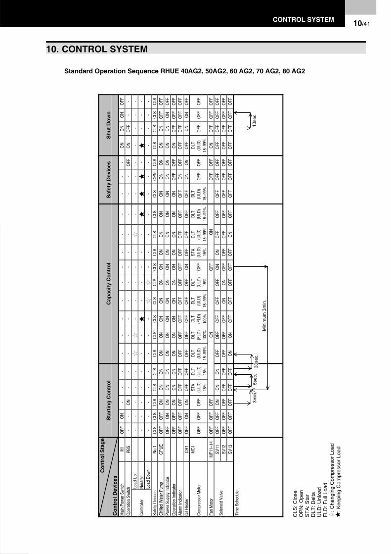
CO
NTR
OL
SY
STE
M10
/41
10. C
ON
TRO
L S
YS
TEM
Con
trol
Sta
ge
Con
trol
Dev
ices
Sta
rtin
g C
ontr
olC
apac
ity C
ontr
olS
afet
y D
evic
esS
hut D
own
Mai
n Po
wer S
witc
hM
IO
FFO
N-
--
--
--
--
--
--
--
ON
ON
ON
OFF
Ope
ratio
n Sw
itch
PBS
--
ON
--
--
--
--
--
--
-O
FFO
NO
FF-
-Lo
ad U
p-
--
--
--
--
-
--
--
--
--
Neut
ral
--
--
--
-
--
--
-
-
--
-Co
ntro
ller
Load
Dow
n-
--
--
--
-
-
--
--
--
--
--
Safe
ty D
evice
sNo
.1CL
SCL
SCL
SCL
SCL
SCL
SCL
SCL
SCL
SCL
SCL
SCL
SCL
SCL
SCL
SO
PNCL
SCL
SCL
SCL
SCL
SCh
illed
Wat
er P
ump
CPUE
OFF
OFF
ON
ON
ON
ON
ON
ON
ON
ON
ON
ON
ON
ON
ON
ON
ON
ON
ON
OFF
OFF
Powe
r Sup
ply
Indi
cato
rO
FFO
NO
NO
NO
NO
NO
NO
NO
NO
NO
NO
NO
NO
NO
NO
NO
NO
NO
NO
NO
FFO
pera
tion
Indi
cato
rO
FFO
FFO
NO
NO
NO
NO
NO
NO
NO
NO
NO
NO
NO
NO
NO
FFO
FFO
NO
FFO
FFO
FFAl
arm
Indi
cato
rO
FFO
FFO
FFO
FFO
FFO
FFO
FFO
FFO
FFO
FFO
FFO
FFO
FFO
FFO
FFO
NO
FFO
FFO
FFO
FFO
FFO
il Hea
ter
CH1
OFF
ON
ON
OFF
OFF
OFF
OFF
OFF
OFF
OFF
ON
OFF
OFF
OFF
OFF
ON
ON
OFF
ON
ON
OFF
MC1
STA
DLT
DLT
DLT
DLT
DLT
DLT
STA
DLT
DLT
DLT
DLT
OFF
OFF
OFF
(ULD
)(U
LD)
(ULD
)(F
LD)
(FLD
)(U
LD)
(ULD
)O
FF(U
LD)
(ULD
)(U
LD)
(ULD
)O
FFO
FF(U
LD)
OFF
OFF
OFF
Com
pres
sor M
otor
15%
15%
15~9
9%10
0%10
0%15
~99%
15%
15%
15~9
9%15
~99%
15~9
9%15
~99%
Fan
Mot
orM
F11~
14O
FFO
FFO
FFO
NO
FFO
NO
FFO
FFO
NO
FFO
FFO
FFSV
11O
FFO
FFO
NO
NO
NO
FFO
FFO
FFO
FFO
FFO
NO
NO
FFO
FFO
FFO
FFO
FFO
FFO
FFO
FFO
FFSV
12O
FFO
FFO
FFO
FFO
FFO
FFO
FFO
FFO
NO
NO
FFO
FFO
FFO
FFO
FFO
FFO
FFO
FFO
FFO
FFO
FFSo
leno
id V
alve
SV13
OFF
OFF
OFF
OFF
OFF
ON
ON
OFF
OFF
OFF
OFF
OFF
ON
OFF
OFF
OFF
OFF
OFF
OFF
OFF
OFF
Tim
e Sc
hedu
le
Standard Operation Sequence RHUE 40AG2, 50AG2, 60 AG2, 70 AG2, 80 AG2
5sec
.3m
in.
30se
c.
Min
imum
3m
in.
10se
c.
CLS
: Clo
seO
PN
: Ope
nS
TA: S
tar
DLT
: Del
taU
LD: U
nloa
dFL
D: F
ull L
oad
: C
hang
ing
Com
pres
sor L
oad
: K
eepi
ng C
ompr
esso
r Loa
d
10. CONTROL SYSTEM
10/41CONTROL SYSTEM

10/4
2C
ON
TRO
L S
YS
TEM
Con
trol
Sta
ge
Con
trol
Dev
ices
Sta
rtin
g C
ontr
olC
apac
ity C
ontr
olS
afet
y D
evic
esS
hut D
own
Mai
n Po
wer S
witc
hM
IO
FFO
N-
--
--
--
--
--
--
--
--
-O
NO
NO
NO
FFO
pera
tion
Switc
hPB
S-
-O
N-
--
--
--
--
--
--
--
-O
FFO
NO
FF-
-Lo
ad U
p-
--
--
--
--
--
-
--
-
--
--
-Ne
utra
l-
--
--
--
--
-
--
--
-
-
--
-Co
ntro
ller
Load
Dow
n-
--
--
--
--
-
-
--
--
--
--
--
-No
.1CL
SCL
SCL
SCL
SCL
SCL
SCL
SCL
SCL
SCL
SCL
SCL
SCL
SCL
SCL
SCL
SCL
SO
PNO
PNCL
SCL
SCL
SCL
SCL
SSa
fety
Dev
ices
No.2
CLS
CLS
CLS
CLS
CLS
CLS
CLS
CLS
CLS
CLS
CLS
CLS
CLS
CLS
CLS
CLS
CLS
CLS
OPN
CLS
CLS
CLS
CLS
CLS
Chille
d W
ater
Pum
pCP
UEO
FFO
FFO
NO
NO
NO
NO
NO
NO
NO
NO
NO
NO
NO
NO
NO
NO
NO
NO
NO
NO
NO
NO
FFO
FFPo
wer S
uppl
y In
dica
tor
OFF
ON
ON
ON
ON
ON
ON
ON
ON
ON
ON
ON
ON
ON
ON
ON
ON
ON
ON
ON
ON
ON
ON
OFF
Ope
ratio
n In
dica
tor
OFF
OFF
ON
ON
ON
ON
ON
ON
ON
ON
ON
ON
ON
ON
ON
ON
ON
ON
OFF
OFF
ON
OFF
OFF
OFF
Alar
m In
dica
tor
OFF
OFF
OFF
OFF
OFF
OFF
OFF
OFF
OFF
OFF
OFF
OFF
OFF
OFF
OFF
OFF
OFF
ON
ON
OFF
OFF
OFF
OFF
OFF
CH1
OFF
ON
ON
OFF
OFF
OFF
OFF
OFF
OFF
OFF
OFF
OFF
ON
OFF
OFF
OFF
OFF
ON
ON
ON
OFF
ON
ON
OFF
Oil H
eate
rCH
2O
FFO
NO
NO
NO
NO
FFO
FFO
FFO
FFO
FFO
FFO
FFO
NO
FFO
FFO
FFO
FFO
FFO
NO
NO
FFO
NO
NO
FFST
ADL
TDL
TDL
TDL
TDL
TDL
TDL
TDL
TST
ADL
TDL
TDL
TDL
T(U
LD)
(ULD
)(U
LD)
(ULD
)(U
LD)
(FLD
)(F
LD)
(ULD
)(U
LD)
(ULD
)(U
LD)
(ULD
)(U
LD)
(ULD
)M
C1O
FFO
FFO
FF15
%15
%15
%15
%15
~99%
100%
100%
15~9
9%15
%O
FF15
%15
~99%
15~9
9%15
~99%
OFF
OFF
OFF
15~9
9%O
FFO
FFO
FF
STA
DLT
DLT
DLT
DLT
DLT
DLT
STA
DLT
DLT
DLT
DLT
DLT
(ULD
)(U
LD)
(ULD
)(F
LD)
(FLD
)(U
LD)
(ULD
)(U
LD)
(ULD
)(U
LD)
(ULD
)(U
LD)
(ULD
)
Com
pres
sor M
otor
MC2
OFF
OFF
OFF
OFF
OFF
15%
15%
15~9
9%10
0%10
0%15
~99%
15%
OFF
15%
15~9
9%15
~99%
15~9
9%15
~99%
OFF
OFF
15~9
9%O
FFO
FFO
FF
MF1
1~16
OFF
OFF
OFF
ON
OFF
ON
OFF
OFF
OFF
ON
OFF
OFF
OFF
Fan
Mot
orM
F21~
26O
FFO
FFO
FFO
FFO
FFO
NO
FFO
NO
FFO
FFO
NO
FFO
FFO
FFSV
11O
FFO
FFO
NO
NO
NO
NO
NO
FFO
FFO
FFO
FFO
FFO
NO
NO
FFO
FFO
FFO
FFO
FFO
FFO
FFO
FFO
FFO
FFSV
12O
FFO
FFO
FFO
FFO
FFO
FFO
FFO
FFO
FFO
FFO
NO
NO
FFO
FFO
FFO
FFO
FFO
FFO
FFO
FFO
FFO
FFO
FFO
FFSV
13O
FFO
FFO
FFO
FFO
FFO
FFO
FFO
NO
NO
FFO
FFO
FFO
FFO
FFO
NO
FFO
FFO
FFO
FFO
FFO
FFO
FFO
FFO
FFSV
21O
FFO
FFO
NO
NO
NO
NO
NO
FFO
FFO
FFO
FFO
FFO
NO
NO
FFO
FFO
FFO
FFO
FFO
FFO
FFO
FFO
FFO
FFSV
22O
FFO
FFO
FFO
FFO
FFO
FFO
FFO
FFO
FFO
FFO
NO
NO
FFO
FFO
FFO
FFO
FFO
FFO
FFO
FFO
FFO
FFO
FFO
FF
Sole
noid
Val
ve
SV23
OFF
OFF
OFF
OFF
OFF
OFF
OFF
ON
ON
OFF
OFF
OFF
OFF
OFF
ON
OFF
OFF
OFF
OFF
OFF
OFF
OFF
OFF
OFF
Tim
e Sc
hedu
le
Standard Operation Sequence RHUE 100AG2, 120 AG2, 140 AG2, 160 AG2
3min
.5s
ec.
5sec
.30
sec.
Min
imum
3m
in.
10se
c.60
sec
The
Com
pres
sor w
hich
sta
rted
final
ly w
ill b
e re
star
ted
first
.
CLS
: Clo
seO
PN
: Ope
nS
TA: S
tar
DLT
: Del
taU
LD: U
nloa
dFL
D: F
ull L
oad
: C
hang
ing
Com
pres
sor L
oad
: K
eepi
ng C
ompr
esso
r Loa
d
10/42 CONTROL SYSTEM

CO
NTR
OL
SY
STE
M10
/43
Con
trol
Sta
ge
Con
trol
Dev
ices
Sta
rtin
g C
ontr
olC
apac
ity C
ontr
olS
afet
y D
evic
esS
hut D
own
Mai
n Po
wer S
witc
hM
IO
FFO
N-
--
--
--
--
--
--
--
--
--
--
ON
ON
ON
OFF
Ope
ratio
n Sw
itch
PBS
--
ON
--
--
--
--
--
--
--
--
--
-O
FFO
NO
FF-
-Lo
ad U
p-
--
--
--
--
--
--
-
--
-
-
--
--
Neut
ral
--
--
--
--
--
-
--
--
-
--
-
--
-Co
ntro
ller
Load
Dow
n-
--
--
--
--
--
-
-
--
--
--
--
--
--
No.1
CLS
CLS
CLS
CLS
CLS
CLS
CLS
CLS
CLS
CLS
CLS
CLS
CLS
CLS
CLS
CLS
CLS
CLS
CLS
OPN
OPN
OPN
CLS
CLS
CLS
CLS
CLS
No.2
CLS
CLS
CLS
CLS
CLS
CLS
CLS
CLS
CLS
CLS
CLS
CLS
CLS
CLS
CLS
CLS
CLS
CLS
CLS
CLS
OPN
OPN
CLS
CLS
CLS
CLS
CLS
Safe
ty D
evice
sNo
.3CL
SCL
SCL
SCL
SCL
SCL
SCL
SCL
SCL
SCL
SCL
SCL
SCL
SCL
SCL
SCL
SCL
SCL
SCL
SCL
SCL
SO
PNCL
SCL
SCL
SCL
SCL
SCh
illed
Wat
er P
ump
CPUE
OFF
OFF
ON
ON
ON
ON
ON
ON
ON
ON
ON
ON
ON
ON
ON
ON
ON
ON
ON
ON
ON
ON
ON
ON
ON
OFF
OFF
Powe
r Sup
ply
Indi
cato
rO
FFO
NO
NO
NO
NO
NO
NO
NO
NO
NO
NO
NO
NO
NO
NO
NO
NO
NO
NO
NO
NO
NO
NO
NO
NO
NO
FFO
pera
tion
Indi
cato
rO
FFO
FFO
NO
NO
NO
NO
NO
NO
NO
NO
NO
NO
NO
NO
NO
NO
NO
NO
NO
NO
NO
FFO
FFO
NO
FFO
FFO
FFAl
arm
Indi
cato
rO
FFO
FFO
FFO
FFO
FFO
FFO
FFO
FFO
FFO
FFO
FFO
FFO
FFO
FFO
FFO
FFO
FFO
FFO
FFO
NO
NO
NO
FFO
FFO
FFO
FFO
FFCH
1O
FFO
NO
NO
FFO
FFO
FFO
FFO
FFO
FFO
FFO
FFO
FFO
FFO
FFO
NO
FFO
FFO
FFO
FFO
NO
NO
NO
NO
FFO
NO
NO
FFCH
2O
FFO
NO
NO
NO
NO
FFO
FFO
FFO
FFO
FFO
FFO
FFO
FFO
FFO
NO
FFO
FFO
FFO
FFO
FFO
NO
NO
NO
FFO
NO
NO
FFO
il Hea
ter
CH3
OFF
ON
ON
ON
ON
ON
ON
OFF
OFF
OFF
OFF
OFF
OFF
OFF
ON
OFF
OFF
OFF
OFF
OFF
OFF
ON
ON
OFF
ON
ON
OFF
STA
DLT
DLT
DLT
DLT
DLT
DLT
DLT
DLT
DLT
DLT
STA
DLT
DLT
DLT
DLT
OFF
OFF
OFF
(ULD
)(U
LD)
(ULD
)(U
LD)
(ULD
)(U
LD)
(ULD
)(F
LD)
(FLD
)(U
LD)
(ULD
)O
FF(U
LD)
(ULD
)(U
LD)
(ULD
)O
FFO
FFO
FFO
FF(U
LD)
OFF
OFF
OFF
MC1
15%
15%
15%
15%
15%
15%
15~9
9%10
0%10
0%15
~99%
15%
15%
15~9
9%15
~99%
15~9
9%15
~99%
STA
DLT
DLT
DLT
DLT
DLT
DLT
DLT
DLT
STA
DLT
DLT
DLT
DLT
DLT
OFF
OFF
OFF
OFF
OFF
(ULD
)(U
LD)
(ULD
)(U
LD)
(ULD
)(F
LD)
(FLD
)(U
LD)
(ULD
)O
FF(U
LD)
(ULD
)(U
LD)
(ULD
)(U
LD)
OFF
OFF
OFF
(ULD
)O
FFO
FFO
FFM
C215
%15
%15
%15
%15
~99%
100%
100%
15~9
9%15
%15
%15
~99%
15~9
9%15
~99%
15~9
9%15
~99%
STA
DLT
DLT
DLT
DLT
DLT
DLT
STA
DLT
DLT
DLT
DLT
DLT
DLT
OFF
OFF
OFF
OFF
OFF
OFF
OFF
(ULD
)(U
LD)
(ULD
)(F
LD)
(FLD
)(U
LD)
(ULD
)O
FF(U
LD)
(ULD
)(U
LD)
(ULD
)(U
LD)
(ULD
)O
FFO
FF(U
LD)
OFF
OFF
OFF
Com
pres
sor M
otor
MC3
15%
15%
15~9
9%10
0%10
0%15
~99%
15%
15%
15~9
9%15
~99%
15~9
9%15
~99%
15~9
9%15
~99%
MF1
1~16
OFF
OFF
OFF
ON
OFF
ON
OFF
OFF
OFF
OFF
ON
OFF
OFF
OFF
MF2
1~26
OFF
OFF
OFF
OFF
ON
OFF
ON
OFF
OFF
OFF
ON
OFF
OFF
OFF
Fan
Mot
orM
F31~
36O
FFO
FFO
FFO
FFO
FFO
NO
FFO
NO
FFO
FFO
NO
FFO
FFO
FFSV
11O
FFO
FFO
NO
NO
NO
NO
NO
NO
NO
FFO
FFO
FFO
FFO
FFO
NO
NO
FFO
FFO
FFO
FFO
FFO
FFO
FFO
FFO
FFO
FFO
FFSV
12O
FFO
FFO
FFO
FFO
FFO
FFO
FFO
FFO
FFO
FFO
FFO
FFO
NO
NO
FFO
FFO
FFO
FFO
FFO
FFO
FFO
FFO
FFO
FFO
FFO
FFO
FFSV
13O
FFO
FFO
FFO
FFO
FFO
FFO
FFO
FFO
FFO
NO
NO
FFO
FFO
FFO
FFO
FFO
NO
FFO
FFO
FFO
FFO
FFO
FFO
FFO
FFO
FFO
FFSV
21O
FFO
FFO
NO
NO
NO
NO
NO
NO
NO
FFO
FFO
FFO
FFO
FFO
NO
NO
FFO
FFO
FFO
FFO
FFO
FFO
FFO
FFO
FFO
FFO
FFSV
22O
FFO
FFO
FFO
FFO
FFO
FFO
FFO
FFO
FFO
FFO
FFO
FFO
NO
NO
FFO
FFO
FFO
FFO
FFO
FFO
FFO
FFO
FFO
FFO
FFO
FFO
FFSV
23O
FFO
FFO
FFO
FFO
FFO
FFO
FFO
FFO
FFO
NO
NO
FFO
FFO
FFO
FFO
FFO
NO
FFO
FFO
FFO
FFO
FFO
FFO
FFO
FFO
FFO
FFSV
31O
FFO
FFO
NO
NO
NO
NO
NO
NO
NO
FFO
FFO
FFO
FFO
FFO
NO
NO
FFO
FFO
FFO
FFO
FFO
FFO
FFO
FFO
FFO
FFO
FFSV
32O
FFO
FFO
FFO
FFO
FFO
FFO
FFO
FFO
FFO
FFO
FFO
FFO
NO
NO
FFO
FFO
FFO
FFO
FFO
FFO
FFO
FFO
FFO
FFO
FFO
FFO
FF
Sole
noid
Val
ve
SV33
OFF
OFF
OFF
OFF
OFF
OFF
OFF
OFF
OFF
ON
ON
OFF
OFF
OFF
OFF
OFF
ON
OFF
OFF
OFF
ON
OFF
OFF
OFF
OFF
OFF
OFF
Tim
e Sc
hedu
le
Standard Operation Sequence RHUE 180AG2, 210 AG2, 240 AG2
60se
c.
3min
.5s
ec.
5sec
.30
sec.
Min
imum
3m
in.
10se
c.5s
ec.
60se
c.Th
e C
ompr
esso
r whi
ch s
tarte
d fin
ally
will
be
rest
arte
d fir
st.
CLS
Clo
seO
PN
: Ope
nS
TA: S
tar
DLT
Del
ta
ULD
: Unl
oad
FLD
: Ful
l Loa
d
: Cha
ngin
g C
ompr
esso
r Loa
d
: Kee
ping
Com
pres
sor L
oad
CONTROL SYSTEM 10/43CONTROL SYSTEM

11/44 MAINTENANCE
11. MAINTENANCE
The unit should be periodically inspected according to thesame items as those described in the paragraph titled"Test Running". In order to ensure dependableperformance and long life operation, the followingadditional items should be given for particular attention.
WARNING:If a fire accidentally occurs, turn OFF the main switchand use an extinguisher for an oil fire and an electricfire.Do not operate the unit near flammable gases suchas lacquer, paint oil, etc. to avoid a fire or anexplosion.Turn OFF the main switch when electrical box coversare removed for setting the temperature. Do notoperate the unit without fixing panels.
DANGER:Switch OFF main interruptor (MI) for any work insideelectrical box.
CAUTION:Perform periodical maintenance according to the"INSTRUCTIONS" to maintain the unit in a goodcondition.Do not touch the parts at the discharge gas side byhand, since the pipes at the discharge side areheated by refrigerant and the temperature becomeshigher than 100 °C.Do not utilise this unit for cooling or heating ofdrinking water or food. Comply with local codes andregulations.Turn OFF all the main switches if refrigerant leakageor chilled water leakage occurs. Also, if the unit cannot be stopped by the control switch, turn OFF all theswitches for power source.
11.1. COMPONENTS Compressor
The semi-hermetic screw compressor requires periodicmaintenance, including replacement of parts. See theHITACHI Service Handbook for Screw Compressors, fordetails.
Air-Side Heat ExchangerInspect the air side heat exchanger and remove anyaccumulated dirt from the coil, at regular intervals. Otherobstacles such as growing grass and pieces of paper,which might restrict Air flow, should also be removed.
Electrical EquipmentAlways pay careful attention to working voltage, amperageand phase balance. Check for faulty contact caused byloosened terminal connections, oxidised contacts, foreignmatter, and others.
Control and Protective DevicesDo not readjust the settings in the field unless the setting ismaintained at the point other than the point listed in thetable on chapter 11.
11.2. LUBRICATION Compressor
The compressors are charged at the factory with thecorrect oil listed on the compressor nameplate. It is notnecessary to add oil, if the refrigerant cycle remains sealed.
Fan MotorBearing of all fan motors are pre-lubricated. Lubrication isnot required.
11.3. DEPOSITLime and other minerals in the chilled water tend to depositon surfaces of plates over a long period of operation. Asdeposits of these minerals increase, excessive loweroperation pressure are detected, indicating evidence ofdeposits on the water side heat exchanger.
CAUTION:Cleaning of plate type heat exchangers shall beperformed by specialists. Please contact yourcontractor or dealer of HITACHI.
Clean the water strainer filter periodically according toits clogging degree.
WARNING:This product is equipped with plate type heatexchangers. In the plate type heat exchanger, waterflows through a narrow space between plates.Therefore, there is a possibility that freezing mayoccur if foreign particles or dust are clogged. In orderto avoid this clogging, provide a 20 mesh waterstrainer at the inlet of the chilled water piping near tothe product. If clogging in the plate type heatexchanger occurs seriously, this will cause insufficientcooling performance or local freezing in the plate typeheat exchanger. It is strongly recommended that theheat exchanger is cleaned at the same time when thefilter is cleaned.Pay attention to the following caution and normalcleaning method. For details, contact your Hitachiinstaller.

MAINTENANCE 11/45
CAUTION:Correctly select cleaning agent depending on scalesin the plate type heat exchangers. The cleaningchemicals are different depending on fouling degree.This plate type heat exchanger is made of stainlesssteel. Do not use a cleaning agent containinghydrochloric acid or fluorine compound. If used, theheat exchanger will be damaged, resulting inrefrigerant leakage.After cleaning with cleaning agent, clean inside ofwater piping including the heat exchangers by usingclean water. Perform water treatment (preventivetreatment) in order to prevent the water circuit fromcorrosion or re-adhering of scales after cleaning.In the case that a cleaning agent is used, adjustconcentration of the cleaning agent, cleaning periodand temperature according to the scale degree.
In the case that acid cleaning is performed,neutralisation treatment is required after cleaning.Treatment for neutralisation fluid should be performedby a waste fluid contractors.The cleaning agent and neutralising agent haveerosiveness and stimulativeness against eyes, skin,mucous membrane etc. Therefore use protectiontools (protection glasses, protection gloves, protectionshoes, protection cloth, protection mask, etc.) in ordernot to absorb or touch these agents during thiscleaning work.
11.4. CLEANING METHOD
N° Name N° Name1 Chiller Unit 6 Waste Fluid Tank2 Chilled Water / Inlet Piping 7 Cleaning Water Tank3 Acid-resistant Type Water Pump 8 Hose4 Hose 9 Chilled Water / Outlet Piping5 Diluted Cleaning Fluid
Water Refrigerant

11/46 MAINTENANCE
1. Installation of Cleaning Circuit Stop the water Chiller unit. Stop the circulating water pump. Disconnect the connections at the chilled water inletand install a circulating water circuit by using an acid-resistant type water pump.
2. Check of Circulating Circuit Pour water in the cleaning tank and operate the acid-resistant type water pump. Check to ensure that no water leakage exists. Check to ensure that the water hose is firmly fixed. Check to ensure that the cleaning agent will notdamage equipment near the water Chiller even ifbubbles occur and touch them. Check to ensure that good ventilation is available. Check to ensure that no abnormal sound occurs.
3. Cleaning Work Discharge water in the water circuit of the airconditioning system. Supply diluted cleaning fluid from the cleaning watertank by operating the acid-resistant pump. Circulate the cleaning fluid for an appropriate period oftime (the operating time should be determinedaccording to the type of cleaning agent, concentrationand fouling degree).
4. Waste Fluid Stop the acid-resistant pump. Put the waste fluid into the waste fluid tank. Supply water into the cleaning tank and operate thepump for water cleaning. Put the cleaning water into the waste fluid tank assame as the waste fluid. Measure pH degree by using a pH test sheet andneutralise the waste fluid by gradually addingneutralising agent. After neutralisation ask a waste fluid treatmentcontractors to handle it.
5. Neutralisation Treatment in the Water Piping Put water into the cleaning tank. Operate the acid-resistant pump after Air-purging. Measure the pH degree and gradually add neutralisingagent until the pH reaches pH = 7. Operate the pump for a specified period of time forneutralisation. Discharge the used water. Operate the circulating pump and clean the circuit withwater until no fouling fluid is observed.
6. Re-starting Reconnect the water piping as they were so that thewater Chiller can operate. After cleaning, perform water treatment (preventivetreatment) in order to prevent the water circuit fromcorrosion.
N° Name1 Saturation Line of R407C2 Area Requiring Cleaning
Suc
tion
Gas
Pre
ssur
e
Chilled Water Outlet Temperature (ºC)
Dis
char
ge G
as P
ress
ure
Hot Water Outlet Temperature (ºC)
Cooling OperationHeating Operation

MAINTENANCE 11/47
11.5. WINTER SHUTDOWNWhen shutting down the unit for winter, clean the insideand outside of the cabinet, and dry the unit. Pump downthe refrigerant to the condenser and close the liquid outletstop valves. This unit should be covered during shutdown,in order to protect it from dust and environmentalconditions. Be sure to tighten the packing glands and thecap nuts of the valves.
Remove the drain plug and drain all residual water from thewater cooler piping systems, as such water may freezeduring the cold season. It is very helpful to supply brine(anti-freezer) to the piping systems.
11.6. SPRING START-UPAfter any extended shutdown period, prepare the unit foroperation as follows.
1. Thoroughly inspect and clean the unit.2. Clean the water piping lines and the strainer.
Inspect the pump and other auxiliary equipment in thepiping line.
3. Tighten all wiring connections and access panel.
CAUTION:When the main switch for this unit has been at theOFF position for an extended period of time, it shouldbe switched ON at least 12 hours before start-up, sothat oil in the compressor discharge casing may bewarmed enough, to prevent oil foaming by the oilheater during start-up.
11.7. PART REPLACEMENT
Replacement of parts should be undertaken by orderingfrom the HITACHI Spare Parts List. CAUTION:
Do not replace with spare parts which are not theequivalent.
11.8. REFRIGERATION CYCLE Strainer
Check for clogging each time when the refrigeration cycleis opened.
Refrigerant ChargeInspect the refrigerant charge of the system by checkingthe discharge and suction pressures. Perform a leakagetest, if any leakage is suspected, and always perform sucha test after a refrigeration cycle component is replaced.When refrigerant charge is required, follow the followinginstructions given for two cases:
1. When Refrigerant Gas Completely Leaked.Before charging the entire cycle must be completelyevacuated and dehydrated. A gauge manifold orequivalent piping preparation shown in the next page isrecommended as a convenient procedure regardingboth charging and evacuation.
Fully open all the stop valves. Connect the evacuation line to the check joints of thehigh and the low pressure sides. Completely evacuate the entire cycle with a vacuumpump. Charge refrigerant to the refrigeration cycle byweighing the charging cylinder. The proper refrigerantcharge is listed on the nameplate. When charging by weight is stopped due to highambient temperature, close the valve and operate theunit after circulating the chilled water through the watercooler and installing a jumper on the low pressureswitch, if required.
2. When Only Additional Refrigerant is Required.Connect a gauge manifold to check joint of low pressureside, and connect a charge cylinder to gauge manifold.Operate the unit after circulating the chilled water andinstall a jumper on the low pressure switch, if required.Repeat the following procedure until pressure becomesproper (refer to page 53).
Charge the gas refrigerant a little slowly intorefrigeration cycle from check joint for low pressure. Check the pressure after refrigeration cycle becomesstable.

11/48 MAINTENANCE
11.9. REFRIGERANT CYCLE DIAGRAM OF HITACHI AIR-TO-WATER HEAT PUMP CHILLER(RHUE 40, 50, 60, 70, 100, 120, 140, 180, 210AG2)
No. Name No. Name1 Compressor 12 Sight Glass2 Air-Side Heat Exchanger 13 Compressor Safety Valve (Option)3 Water Side Heat Exchanger 14 Stop Valve (Option)4 Biflow drier 15 Stop Valve (Option)5 Electronic Expansion Valve 16 Compressor Dual Safety Valve (Option)6 Check Valve 17 Stop Valve7 Stop Valve (with check Joint) A High Pressure Gauge8 High Pressure Switch B Low Pressure Gauge9 Pressure Sensor (Low) C Stop Valve
10 Pressure Sensor (High) D Charging Cylinder11 Pressure Relief Valve E Vacuum Pump
NOTE:R407C shall be charged by LIQUID.
Chilled Water Inlet
Chilled Water Outlet
OptionOption
Option
Option
GaugeManifold
Unit Side
Charging EvacuationFlange ConnectionFlare ConnectionSolder ConnectionCooling OperationHeating Operation

MAINTENANCE 11/49
11.10. REFRIGERANT CYCLE DIAGRAM OF HITACHI AIR-TO-WATER HEAT PUMP CHILLER(RHUE 80, 160, 240 AG2) WITH ECONOMIZER.
NOTE:R407C shall be charged by LIQUID.
No. Name No. Name1 Compressor 16 Compressor Dual Safety Valve (Option)2 Air Side Heat Exchanger 17 4-Way Valve3 Water Side Heat Exchanger 18 Accumulator4 Biflow drier 19 Liquid Tank5 Electronic Expansion Valve 20 Solenoid Valve6 Check Valve 21 Capillary Tube7 Stop Valve (with check Joint) 22 Economizer8 High Pressure Switch 23 Strainer9 Pressure Sensor (Low) 24 Pressure Switch
10 Pressure Sensor (High) A High Pressure Gauge11 Pressure Relief Valve B Low Pressure Gauge12 Sight Glass C Stop Valve13 Compressor Safety Valve (Option) D Charging Cylinder14 Stop Valve (Option) E Vacuum Pump15 Stop Valve (Option)
Chilled Water Inlet
Chilled Water Outlet
Option
OptionOption Option
GaugeManifold
Unit Side
Charging Evacuation
Flange ConnectionFlare ConnectionSolder ConnectionCooling OperationHeating Operation

11/50 MAINTENANCE
CAUTION:Do not charge OXYGEN, ACETYLENE or otherflammable and poisonous gases into the refrigerationcycle when performing a leakage test or an airtighttest. These types of gases are extremely dangerous,because explosion can occur. It is recommended thatcompressed air or nitrogen is charged for these typesof tests.
Mineral deposits on water cooler plates act asthermal insulators, and also act as resistance againstwater flow, causing a decrease of the water flowrunning through them, and resulting in a decreasingof the cooling capacity. Deposits on the plates shouldbe inspected at regular intervals. Experience with thewater Chiller will dictate accurate inspection intervals.
These deposits should be removed by circulatingdiluted acid through the water passes after the waterhas been drained. As water in different localitiescontains different minerals, different acids arerequired, depending upon the thickness of thedeposits.
This unit is equipped with an operation hour meter. Inthe case that the total operation time reaches 24,000hours or 3 years pass after installation, exchange thebearings of the compressor. For details, refer to theService Handbook for HITACHI Screw Compressors.
For R407C refrigerant system, charge the refrigerantwith liquid condition to avoid its composition change.
11.11. COMPRESSOR REMOVAL
When Removing the CompressorRemove the compressor while completing the followingprocedures.
1. Collect all refrigerant into a condenser before thiswork.
2. Turn off the switch DSW3 of the PCB in the magneticswitch box in order not to operate the compressorexcept for the cycle.
3. Circulate the chilled water sufficiently through thewater cooler, and operate the water Chiller for 10minutes, and check to ensure that the oil level ismaintained at a stable condition.
4. Stop the water Chiller and completely close the liquidstop valve.
5. Operate the water Chiller after circulating waterthrough the water cooler.
6. Stop the water Chiller when the low pressure reachesat approximately 0.05 MPa. Do not operate at apressure lower than 0.05 MPa. If operated, it willcause a damage to the compressor.
7. Wait for several minutes. If the low pressure increase upto 0.45 to 0.5 MPa, repeat the above procedures 5 and6 four or five times.
8. Turn OFF the power supply to the unit.9. After these works above, almost all refrigerant can be
collected in the condenser.10.Recover the rest of refrigerant from the water cooler and
the compressor.11.Remove the bolts on the discharge and suction flanges
of the compressor.12.Remove all the wiring of the compressor.13.Remove the bolts fixing the compressor.14.Remove the compressor.

MAINTENANCE 11/51
11.12. SAFETY AND PROTECTION CONTROLThe safety and protective devices are equipped with theunit to ensure dependable and long life operation.
Their functions should be carefully noted, and fieldadjustment is not recommended, if the setting is maintainedat the point listed in the table.
Compressor protection1. Fuse and thermal relay equipped in the control box cut
out each compressor operation when the current to thecompressor exceeds the setting
2. The internal thermostat embedded in the motor windingcuts out each operation, when the temperature exceedsthe setting
3. The oil heater in the compressor prevents from oilfoaming during cold starting. This heater warms the oil,while the compressor is stopped
Refrigeration Cycle1. The high pressure switch and low pressure control
protect against excessive discharge pressure andexceedingly low suction pressure. The switch andcontrol cut out compressor operation when dischargepressure or suction pressure is abnormal.
2. The pressure relief valve is equipped on discharge gasline. When high pressure exceeds the setting, gasrefrigerant will be discharged to prevent abnormal highpressure
Condenser Fan Motor Protection Fuse and internal thermostat are equipped
The internal thermostat embedded in fan motor windingcut out fan operation and compressor operation, whenthe temperature of the motor winding exceeds thesetting
Water Side Heat ExchangerPump interlock, freeze protection thermostat, lowpressure control and suction gas thermostat can protectwater cooler against water cooler freezing
Model RHUE – AG2 40 50 60 70 80 100 120 140 160 180 210 240For Compressor High Pressure Switch Manual Reset, Non-Adjustable ( One Switch for Each Compressor Motor )
Cut - Out MPa 2,74 2,74 2,74 2,74 2,74 2,74 2,74 2,74 2,74 2,74 2,74 2,74 Low Pressure Control Electronic Control
Cut - Out MPa 0,05 0,05 0,05 0,05 0,05 0,05 0,05 0,05 0,05 0,05 0,05 0,05Internal Thermostat forCompressor Manual Reset, Non-Adjustable ( One Switch for Each Compressor Motor )
Cut - Out °C 115 115 115 115 115 115 115 115 115 115 115 115Cut - In °C 93 93 93 93 93 93 93 93 93 93 93 93
Compressor Motor(380-415V / 50Hz) ( 3 Fuses for Each Compressor )
Fuse A 125 125 125 160 160 125 125 160 160 125 160 160Manual Reset, Adjustable ( One Three-Phase Set for Each Compressor Motor )
Thermal Relay A 54 60 70 80 90 60 70 80 90 70 80 90Manual Reset, Adjustable ( One Three-Phase Set for Each Compressor Motor )
Circuit Protector (Option) A 112 112 136 160 160 112 136 160 160 136 160 160Oil Heater ( One Heater for Each Compressor Motor ) Capacity W 150 150 150 150 150 150 150 150 150 150 150 150Discharge Gas TemperatureControl ( One for Each Circuit )
Cut - Out °C 140 140 140 140 140 140 140 140 140 140 140 140CCP Timer Non-Adjustable ( One Timer for Each Compressor Motor ) Setting Timer S 180 180 180 180 180 180 180 180 180 180 180 180 Star - Delta S 5 5 5 5 5 5 5 5 5 5 5 5 Unloading During Starting S 30 30 30 30 30 30 30 30 30 30 30 30For Control Circuit Fuse A 6 6 6 6 6 6 6 6 6 6 6 6For Refrigerant Circuit Pressure Relief Valve ( One for Each Circuit )
Setting Pressure MPa 3,0 3,0 3,0 3,0 3,0 3,0 3,0 3,0 3,0 3,0 3,0 3,0Freeze Protection Control ( One for Each Water Cooler )
Cut - Out °C 2 2 2 2 2 2 2 2 2 2 2 2Fan Motor (380-415V / 50Hz) ( 3 Fuses for Each Circuit ) Fuse A 12 12 12 12 12 12 12 12 12 12 12 12
( One Fuse for Each Fan ( Both DC Fan and AC Fan ) ) Fuse A 12 12 12 12 12 12 12 12 12 12 12 12
Manual Reset, Adjustable ( One Protector for Each Fan ( Both DC Fan and AC Fan ))
Circuit Protector (Option) A 12 12 12 12 12 12 12 12 12 12 12 12

11/52 MAINTENANCE
11.12.1. OPTIONS
Following table shows options:( mark shows available)
Specifications Standard Option RemarksLow Noise OptionSuper Low Noise OptionGeneralLow Ambient Fan Control (- ℃15 )
Outlet Temperature: 0 ~ (4°C ) (Low1)Outlet Temperature: -1 ~ (-5°C) (Low2)Low Water
TemperatureOutlet Temperature: -6 ~ (-10°C) (Low3)
Compressor Compressor EnclosureCircuit Breaker Protection For Each CompressorCurrent LimiterMain Isolator SwitchLocal/Remote Changeover SwitchIndividual Alarm By Alarm CodeOperation Hour MeterPressure Sensor (High and Low)Pump Freeze Protection Operation Pump ON/OFF OperationPump Operation Circuit Pump ON/OFF ContactNon Voltage Contact for Remote indication Pump, Operation, AlarmDC24V External Control Level or pulseShort Period Power OFF ProtectionPower Failure Recover Control2 Different Temperature Setting For Heat Storage ApplicationRemote Control Operation (Field Supplied) AC 220-240VBMS Control (HARC-70CE1 /OP) LON-WORKSRemote Controller (CSC-5S)Numbered Cables
ControlSystem
Output ON/OFF Signal for Free CoolingCoil Guard (Unit Both Side)Coated FinAir Side
Heat ExchangerCopper FinIndependent Circuit
Discharge ValveSuction ValveCompressor Safety ValveCompressor Dual Safety Valve
Pressure Display (High and Low) Standard:Display on Operation Panel
RefrigerationCycle
Suction Pipe Insulation
PED Certificate (97/23/EC) PED: PressureEquipment Directive
10 bar Water PressurePN 16 Flange With Companion FlangeDifferent Water Pressure SwitchWater Flow Switch (Field Install)Water Cooler Heater
Water SideHeat Exchanger
Common Water Pipe For Air CooledWitness Test
Others Foundation Rubber Mats

MAINTENANCE 11/53
11.13. NORMAL OPERATING PRESSURE
Check to ensure that Chiller is operating within the working range as shown below, after at least 15 minutes operation.
CAUTION: Periodical MaintenancePerform periodical maintenance according to the"INSTRUCTIONS" to maintain the unit in a goodcondition. FireIf a fire accidentally occurs, turn OFF the main switchand use an extinguisher for an oil fire and electric fire. Flammable GasesDo not operate the unit near the flammable gasessuch as lacquer, paint, oil, etc. to avoid a fire or anexplosion. Service Panels and Electrical Box CoverTurn OFF the main switch when service panels orelectrical box covers are removed for setting thetemperature.Do not operate the unit without fixing panels. Heated PipeDo not touch the parts at discharge gas side by hand,since the pipes at the discharge side are heated byrefrigerant and temperature becomes higher than100°C. UseDo not utilise this unit for cooling of drinking water orfood. Comply with local codes and regulations. FailureTurn OFF all the main switches if refrigerant leakage
or chilled water leakage occurs. Also, if the unit cannot be stopped by the control switch, turn OFF all theswitches for power source. Activation of Safety DeviceIn the case that one of safety devices is activated andunit is stopped, remove the cause of the stoppageand restart the unit. The protection devices areutilised to protect the unit from an abnormaloperation.Therefore, if one of safety devices is activated,remove the cause by referring the "Troubleshooting"in the "INSTRUCTION" or call the local agency. FuseUtilise a fuse with specified capacity. Do not use asteel wire or a copper wire instead of a fuse. If anincorrect wire is utilised, a serious accident such as afire will occur. Safety DevicesDo not make a short-circuit at the protection line. If ashort-circuit is made, a serious accident will occur.
Setting of Safety devicesDo not change the setting of safety devices, ifchanged, a serious accident will occur.Do not touch any electrical parts except for theoperation switches during the operation.Do not press the button on the magnetic switch. Ifpressed, a serious accident will occur.
-Conditions- Compressor: 100 % Load Air Side Heat
Exchanger Fans: 4 or 6 Fans Running each Cycle
Hot Water Outlet Temperature (°C )
Dis
char
ge G
as P
ress
ure
(MP
a)
351.21.41.6
2.01.8
2.42.2
2.6
40 5545 50
Standard Working Range0
0.2
0.6
0.4
-10 0 10 20Ambient Temperature (°C WB)
Suc
tion
Gas
Pre
ssur
e(M
Pa)
Standard Working
0
0.2
0.6
0.4
5 7 9 15
Chilled Water Temperature (°C )
Suc
tion
Gas
Pre
ssur
e(M
Pa)
11 13
Standard Working
Ambient Temperature (°C DB)
Dis
char
ge G
as P
ress
ure
(MP
a)
1.0
2.0
1.5
2.5
0 3010 20
Standard Working Range
-10 40
Cooling operation
Heating operation

11/54 MAINTENANCE
11.14. TEST RUNNING AND MAINTENANCE RECORD
MODEL: RHUE MFG. NO.
COMPRESSOR MFG. NO.
CUSTOMER NAME AND ADDRESS DATE
Is there adequate water flow for the water side heat exchanger?
Has all water piping been checked for leakage?
Has the unit been operated for at least twenty minutes?
Check Ambient Temperature:
ºC
Check Chillerd or Hot Water Temperature:
Inlet ºC Outlet ºC
Check Water Flow:
m3/h
Check Suction Line Temperature and Superheat:
Suction Line Temperature ºC ºC ºC
Superheat deg deg deg
Check Pressure:
Discharge Pressure MPa MPa MPa
Suction Pressure MPa MPa MPa
Check Running Current:
A A A
Check Voltage for System:
R-S, S-T, T-R= V V V
Has the unit been checked for refrigerant leakage?
Is the unit clean inside and outside?
Are all cabinet panels free from rattling?

MAINTENANCE 11/55
11.15. DAILY OPERATING RECORDS
Model:
Date:
Weather:
Time of Operation : Start, Stop. (Operation hour: )
Sampling Time
Compressor Number
Term
Ambient Temperature DB ºC
WB ºC
Compressor High Pressure MPa
Low Pressure MPa
Voltage V
Current A
Chiller or Hot WaterTemperature Inlet ºC
Outlet ºC
Current for Chilled Water Pump A
NOTES:
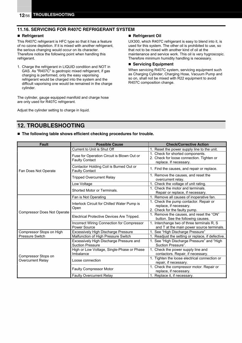
12/56 TROUBLESHOOTING
11.16. SERVICING FOR R407C REFRIGERANT SYSTEM Refrigerant
This R407C refrigerant is HFC type so that it has a featureof no ozone depletion. If it is mixed with another refrigerant,the serious changing would occur on its character.Therefore notice the following point when handling thisrefrigerant.
1. Charge the refrigerant in LIQUID condition and NOT inGAS. As "R407C" is geotropic mixed refrigerant, if gascharging is performed, only the easy vaporisingrefrigerant would be charged into the system and thedifficult vaporising one would be remained in the chargecylinder.
The cylinder, gauge equipped manifold and charge hoseare only used for R407C refrigerant.
Adjust the cylinder setting to charge in liquid.
Refrigerant OilUX300, which R407C refrigerant is easy to blend into it, isused for this system. The other oil is prohibited to use, sothat not to be mixed with another kind of oil at themaintenance and service work. This oil is very hygroscopic.Therefore minimum humidity handling is necessary.
Servicing EquipmentWhen servicing R407C system, servicing equipment suchas Charging Cylinder, Charging Hose, Vacuum Pump andso on, shall not be mixed with R22 equipment to avoidR407C composition change.
12. TROUBLESHOOTING The following table shows efficient checking procedures for trouble.
Fault Possible Cause Check/Corrective ActionCurrent to Unit is Shut Off 1. Reset the power supply line to the unit.
Fuse for Operation Circuit is Blown Out orFaulty Contact
1. Check for shorted components.2. Check for loose connection. Tighten or
replace. If necessary.Contactor Holding Coil is Burned Out orFaulty Contact 1. Find the causes, and repair or replace.
Tripped Overcurrent Relay 1. Remove the causes, and reset theovercurrent relay.
Low Voltage 1. Check the voltage of unit rating.
Fan Does Not Operate
Shorted Motor or Terminals. 1. Check the motor and terminals.Repair or replace, if necessary.
Fan is Not Operating 1. Remove all causes of inoperative fan.
Interlock Circuit for Chilled Water Pump isOpen
1. Check the pump contactor. Repair orreplace, if necessary.
2. Check for the faulty pump.
Electrical Protective Devices Are Tripped. 1. Remove the causes, and reset the “ON”button. See the following causes.
Compressor Does Not Operate
Incorrect Wiring Connection for CompressorPower Source
1. Interchange two of three terminals R, Sand T at the main power source terminals.
Excessively High Discharge Pressure 1. See “High Discharge Pressure”Compressor Stops on HighPressure Switch Malfunction of High Pressure Switch 1. Readjust the setting or replace, if defective.
Excessively High Discharge Pressure andSuction Pressure
1. See “High Discharge Pressure” and “HighSuction Pressure”.
High or Low Voltage, Single-Phase or PhaseImbalance
1. Check the power supply line andcontactors. Repair, if necessary.
Loose connection 1. Tighten the loose electrical connection orrepair, if necessary.
Faulty Compressor Motor 1. Check the compressor motor. Repair orreplace, if necessary.
Compressor Stops onOvercurrent Relay
Faulty Overcurrent Relay 1. Replace it, if necessary.

TROUBLESHOOTING 12/57
The following table shows efficient checking procedures for trouble.
Fault Possible Cause Check/Corrective Action
Excessively Low Chilled water OutletTemperature
1. Check for excessively low setting of thechilled water setting knob.
Defective Thermistor 1. Check for malfunction of the thermistor.Replace, if necessary.
Shortage of Chilled Water Flow 1. Check the rotation of the pump.
Compressor Stops on FreezeProtection Control.(For Cooling Operation)
Air in water Circuit 1. Purge air.High or Low Voltage, Single-Phase or PhaseImbalance
1. Check the power supply line and contactor.Repair, if necessary.
Excessive Superheat 1. Check for refrigerant leakage.
Defective Element 1. Check the contact of the internalthermostat during the cold condition.
Compressor Stops on InternalThermostat or Discharge GasTemperature Control.
Excessive High Discharge Pressure and LowSuction Pressure
1. See “High Discharge Pressure” and “LowSuction Pressure”.
High Discharge Pressure or Low SuctionPressure
1. See “High Discharge Pressure” and “LowSuction Pressure”.
Improper Thermostat Setting 1. Readjust the setting.
Defective Unload Mechanism 1. Adjust unload mechanism. Repair orreplace unloaded parts, if necessary.
Insufficient Cooling or Heating
Internal leakage of Four-Way Valve 1. Repair or replace the Four-Way-Valve.
Slugging Due to Liquid Flooding Back toCompressor
1. Check the superheat of suction gas. Checkthe position of Expansion Valve coil.Repair or replace if necessary.Noisy Compressor
Worn parts 1. Check for the sound of internal parts.Replace the compressor, if necessary.
Miscellaneous Noise Loose Fixed Screw 1. Tighten the screws of all parts.
Trouble with the Thermistor 1. Adjust the setting temperature.2. Replace the thermistor.
Trouble with the Solenoid Valve 1. Check the coil in the solenoid valve.2. Check oil passage for clogging.Unloaded Does not Function
Worn Unloader Mechanism 1. Check the unloaded system parts in thecompressor.
High Air Side Heat Exchanger Temperature orInsufficient Air Flow Through the Air Side HeatExchanger
1. Check the fan operation.2. Check for coil clogging; clean, if necessary.
Defective Check Valve or partially ClosedLiquid Line Valve
1. Check the valves, capillary and strainer.Replace, if necessary.
Overcharged Refrigerant 1. Adjust the refrigerant quantity.Air or Non-Condensable Gas in the RefrigerantCycle. 1. Purge the gas from the refrigerant cycle.
High Discharge Pressure(For Cooling operation)
Suction Pressure is Higher than Standard 1. See “High Suction Pressure”.Extremely Cold Condenser Air 1. Check the ambient Temperature.Insufficient Refrigerant Charge 1. Add Refrigerant.Leakage from the Compressor DischargeValve
1. Replace the valves. Replace thecompressor, if required.
Low Discharge Pressure(For Cooling operation)
Suction Pressure is Lower than Standard 1. See “ Low Suction Pressure”
High Inlet Temperature of Chilled Water 1. Check the insulation of the piping.2. Check the installation specifications.High Suction Pressure
(For Cooling operation) Excessive Opening of Expansion Valve 1. Check the position of Expansion Valve coil,or replace, if defective.
Low Inlet Temperature of Chilled Water 1. Check the installation specifications.Improperly controlled Expansion Valve orFaulty Valve
1. Check the position of Expansion Valve coil.Repair or replace, if necessary.
Insufficient Refrigerant Charge 1. Add Refrigerant.Excessive Oil in the Water Cooler 1. Purge Oil.
Low Suction Pressure(For Cooling operation)
Scales on Water Cooler Plates 1. Clean the plates.
Insufficient Water Flow 1. Check the temperature difference betweenInlet and Outlet Water.
Overcharged Refrigerant 1. Adjust the refrigerant quantityAir or Non-condensable Gas in the RefrigerantCycle 1. Purge the gas from refrigerant cycle
Scales on Water side Heat Exchanger Plate 1. Clean the plate
High Discharge Pressure(For Heating operation)
High Outlet Temperature of Hot Water 1. Check the water temperature

12/58 TROUBLESHOOTING
Fault Possible Cause Check/Corrective ActionExtremely Cold Hot Water 1. Check the hot water temperatureInsufficient Refrigerant Charge 1. Add Refrigerant.
Leakage from the Compressor Discharge Valve 1. Replace the valves. Replace thecompressor, if required.
Low Discharge Pressure(For Heating operation)
Suction Pressure is Lower than Standard 1. See “ Low Suction Pressure”High Inlet Temperature of Air Side HeatExchanger Air 1. Check the ambient temperatureHigh Suction Pressure
(For Heating operation) Excessive Opening of Expansion Valve 1. Check the position of Expansion Valve coil, orreplace, if defective.
Insufficient Refrigerant Charge 1. Add Refrigerant.Insufficient Air Flow 1. Check the fan operationShort-Circuit Air flow 1. Remove the cause of short-circuitLow Suction Pressure
(For Heating operation)Insufficient Defrost Operation 1. Check the four-way valve and thermistor for
defrost operation. Replace if necessaryFaulty Four-Way Valve or Thermistor for defrostcontrol 1. Check their operation. Replace if necessary.
Short-Circuit Air 1. Remove the cause of short-circuitExcessive Deposit ofFrost on Air SideHeat Exchanger Rain or Snow Fall around 0 Ambient
Temperature with high humidity 1. Utilize the manual defrosting switch

GENERAL SPECIFICATIONS 13/59
13. GENERAL SPECIFICATIONS
13.1. GENERAL DATA
Model RHUE40AG2 RHUE50AG2 RHUE60AG2 RHUE70AG2Cooling Capacity kW 106 123 148 169Heating Capacity kW 110 127 152 185Total Power Input in Cooling kW 36.4 42.7 52.3 59.8Total Power Input in Heating kW 40.7 44.5 54.3 67.7
Height mm 2,430 2,430 2,430 2,430Outer Dimension Width mm 1,900 1,900 1,900 1,900
Depth mm 1,900 1,900 1,900 2,500Cabinet Colour - Natural GreyNet Weight kg 1,550 1,600 1,670 1,880Compressor Type - Semi-Hermetic Screw Type Models - 40ASC-Z 40ASC-Z 50ASC-Z 60ASC-Z Quantity - 1 1 1 1 Oil Heater W 150
- Continuous Capacity ControlCapacity Control % 15 ~ 100Water Side Heat Exchanger - Brazing Plate TypeAir Side Heat Exchanger - Multi-Pass Cross Finned Tube Fan Motor (pole) kW 0.38(8) Quantity - 4 4 4 6Refrigerant Type - R407C (Factory Charged) Flow Control - Electronic Expansion Valve Number of Independent Circuit - 1 1 1 1Oil Type - JAPAN ENERGY FREOL UX300 (Ester)Water pipe Connection - 3” Victaulic (1×Inlet / 1×Outlet )Control System - Micro-Processor ControlChilled Water Outlet Temperature °C 5 ~ 15Heated Water Outlet Temperature °C 35 ~ 55Condenser Air Inlet Temperature °C -15 ~ 46 for Cooling OperationEvaporator Air Inlet Temperature °C DB:-9.5~ ~21/ WB:-10 15.5 for Heating OperationPermissible Water Pressure Max. MPa 1.0
Safety and Protection Devices -
Reverse Phase Protection, Fuse and Thermal Relay for Compressor,Internal Thermostat for Compressor, Compressor Oil Heater,Fuse and Internal Thermostat for Fan Motor, Control Circuit Fuse,High Pressure Switch, Low Pressure Control, High Pressure Relief Valve,Discharge Gas Temperature Control, Suction Gas Temperature Control,Freeze Protection Control and Compressor Operation Hour Meter
Power Supply - 3~, N / 380V-415V / 50Hz
NOTE:(1) The nominal cooling capacities are based on the European Standard EN12055.- Chilled Water Inlet / Outlet Temperature : 12 / 7 °C- Condenser Inlet Air Temperature : 35 °C
(2) The nominal heating capacities are based on the European Standard EN12055.- Heated Water Inlet / Outlet Temperature : 40 / 45 °C- Evaporator Inlet Air Temperature : 6 °C (WB)

13/60 GENERAL SPECIFICATIONS
Model RHUE80AG2 RHUE100AG2 RHUE120AG2 RHUE140AG2Cooling Capacity kW 195 246 296 338Heating Capacity kW 185 254 305 371Total Power Input in Cooling kW 69.6 85.4 104.5 119.6Total Power Input in Heating kW 67.7 89.0 108.6 135.5
Height mm 2,430 2,430 2,430 2,430Outer Dimension Width mm 1,900 1,900 1,900 1,900
Depth mm 2,500 3,800 3,800 5,000Cabinet Colour - Natural GreyNet Weight kg 1,950 3,050 3,250 3,670Compressor Type - Semi-Hermetic Screw Type Models - 60ASC-Z 40ASC-Z 50ASC-Z 60ASC-Z Quantity - 1 2 2 2 Oil Heater W 150 150×2
- Continuous Capacity ControlCapacity Control % 15 ~ 100Water Side Heat Exchanger - Brazing Plate TypeAir Side Heat Exchanger - Multi-Pass Cross Finned Tube Fan Motor (pole) kW 0.38(8) Quantity - 6 8 8 12Refrigerant Type - R407C (Factory Charged) Flow Control - Electronic Expansion Valve Number of Circuit - 1 2 2 2Oil Type - JAPAN ENERGY FREOL UX300 (Ester)
Water pipe Connection -3” Victaulic(1×Inlet /1×Outlet )
3” Victaulic (2×Inlet / 2×Outlet )
Control System - Micro-Processor ControlChilled Water Outlet Temperature °C 5 ~ 15Heated Water Outlet Temperature °C 35 ~ 55Condenser Air Inlet Temperature °C -15 ~ 46 for Cooling OperationEvaporator Air Inlet Temperature °C DB:-9.5~ ~21/ WB:-10 15.5 for Heating OperationPermissible Water Pressure Max. MPa 1.0
Safety and ProtectionDevices -
Reverse Phase Protection, Fuse and Thermal Relay for Compressor,Internal Thermostat for Compressor, Compressor Oil Heater,Fuse and Internal Thermostat for Fan Motor, Control Circuit Fuse,High Pressure Switch, Low Pressure Control,High Pressure Relief Valve, Discharge Gas Temperature Control,Suction Gas Temperature Control, Freeze Protection Controland Compressor Operation Hour Meter
Power Supply - 3~, N / 380V-415V / 50Hz
NOTE:(1) The nominal cooling capacities are based on the European Standard EN12055.- Chilled Water Inlet / Outlet Temperature : 12 / 7 °C- Condenser Inlet Air Temperature : 35 °C
(2) The nominal heating capacities are based on the European Standard EN12055.- Heated Water Inlet / Outlet Temperature : 40 / 45 °C- Evaporator Inlet Air Temperature : 6 °C (WB)

GENERAL SPECIFICATIONS 13/61
Model RHUE160AG2 RHUE180AG2 RHUE210AG2 RHUE240AG2Cooling Capacity kW 390 444 507 585Heating Capacity kW 371 457 556 556Total Power Input in Cooling kW 139.1 156.8 179.4 208.7Total Power Input in Heating kW 135.5 162.9 203.2 203.2
Height mm 2,430 2,430 2,430 2,430Outer Dimension Width mm 1,900 1,900 1,900 1,900
Depth mm 5,000 5,700 7,500 7,500Cabinet Colour - Natural GreyNet Weight kg 3,780 4,780 5,440 5,650Compressor Type - Semi-Hermetic Screw Type Models - 60ASC-Z 50ASC-Z 60ASC-Z 60ASC-Z Quantity - 2 3 3 3 Oil Heater W 150×2 150×3
- Continuous Capacity ControlCapacity Control % 15 ~ 100Water Side Heat Exchanger - Brazing Plate TypeAir Side Heat Exchanger - Multi-Pass Cross Finned Tube Fan Motor (pole) kW 0.38(8) Quantity - 12 12 18 18Refrigerant Type - R407C (Factory Charged) Flow Control - Electronic Expansion Valve Number of Circuit - 2 3 3 3Oil Type - JAPAN ENERGY FREOL UX300 (Ester)
Water pipe Connection -3” Victaulic
(2×Inlet / 2×Outlet )
3” Victaulic (3×Inlet / 3×Outlet )
Control System - Micro-Processor ControlChilled Water outlet Temperature °C 5 ~ 15Heated Water Outlet Temperature °C 35 ~ 55Condenser Air Inlet Temperature °C -15 ~ 46 for Cooling OperationEvaporator Air Inlet Temperature °C DB:-9.5~ ~21/ WB:-10 15.5 for Heating OperationPermissible Water Pressure Max. MPa 1.0
Safety and ProtectionDevices -
Reverse Phase Protection, Fuse and Thermal Relay for Compressor,Internal Thermostat for Compressor, Compressor Oil Heater,Fuse and Internal Thermostat for Fan Motor, Control Circuit Fuse,High Pressure Switch, Low Pressure Control,High Pressure Relief Valve, Discharge Gas Temperature Control,Suction Gas Temperature Control, Freeze Protection Controland Compressor Operation Hour Meter
Power Supply - 3~, N / 380V-415V / 50Hz
NOTE:(1) The nominal cooling capacities are based on the European Standard EN12055.- Chilled Water Inlet / Outlet Temperature : 12 / 7 °C- Condenser Inlet Air Temperature : 35 °C
(2) The nominal heating capacities are based on the European Standard EN12055.- Heated Water Inlet / Outlet Temperature : 40 / 45 °C- Evaporator Inlet Air Temperature : 6 °C (WB)

14/62 DRAWINGS
14. DRAWINGS
14.1. DIMENSIONAL DRAWING
RHUE 40AG2, RHUE 50AG2, RHUE 60AG2
ModelRHUE 40AG2RHUE 50AG2RHUE 60AG2
Air Inlet
Air Inlet
(3B Victaulic connection)
(∅88.9 Welding connection)
(Mounting holes)
Air Outlet

DRAWINGS 14/63
RHUE 70AG2, RHUE 80AG2
ModelRHUE 70AG2RHUE 80AG2
Air Inlet
(3B Victaulic connection)
(∅88.9 Welding connection)
(Mounting holes)
Air Outlet
Air Inlet

14/64 DRAWINGS
RHUE 100AG2, RHUE 120AG2
ModelRHUE 100AG2RHUE 120AG2
Air Inlet
(3B Victaulic connection)
(∅88.9 Weldingconnection)
(Mounting holes)
Air Outlet
Air Inlet

DRAWINGS 14/65
RHUE 140AG2, RHUE 160AG2
ModelRHUE 140AG2RHUE 160AG2
Air Inlet
(3B Victaulic connection)
(∅88.9 Weldingconnection)
(Mounting holes)
Air Outlet
Air Inlet Air Inlet
Air Inlet
Air Inlet Air Inlet

14/66 DRAWINGS
RHUE 180AG2
RHUE 210, RHUE 240AG2
ModelRHUE 180AG2
(3B Victaulic connection)
(∅88.9 Welding connection)(Mounting holes)
Air Outlet
Air Inlet
Air Inlet Air Inlet
Air Inlet
Air Inlet
IN
OUT
IN
OUT
IN
OUT
ModelRHUE 210AG2RHUE 240AG2
(3B Victaulic connection)(∅88.9 Welding connection)
(Mounting holes)
Air Outlet
Air Inlet Air Inlet
Air Inlet Air Inlet
Air Inlet
Air Inlet
IN
OUT
IN
OUT
IN
OUT

DRAWINGS 14/67
14.2. WIRING DIAGRAM
POWER CIRCUIT FOR RHUE 40AG2, RHUE 50AG2, RHUE 60AG2, RHUE 70AG2, RHUE 80AG2
Mod
els
RH
UE
40A
G2
RH
UE
50A
G2
RH
UE
60A
G2
RH
UE
70A
G2
RH
UE
80A
G2
Onl
y 70
& 8
0 H
P

14/68 DRAWINGS
POWER CIRCUIT FOR RHUE 100AG2, RHUE 120AG2, RHUE 140AG2, RHUE 160AG2
Mod
els
RH
UE
100
AG
2
RH
UE
120
AG
2R
HU
E 1
40A
G2
RH
UE
160
AG
2
Onl
y 14
0 &
160
HP
Onl
y 14
0 &
160
HP

DRAWINGS 14/69
POWER CIRCUIT FOR RHUE 180AG2, RHUE 210AG2, RHUE 240AG2
Mod
els
RH
UE
180
AG
2
RH
UE
210
AG
2R
HU
E 2
40A
G2
Onl
y 21
0 &
240
HP
Onl
y 21
0 &
240
HP
Onl
y 21
0 &
240
HP

14/70 DRAWINGS
CONTROL CIRCUIT FOR RHUE 40AG2, RHUE 50AG2, RHUE 60AG2, RHUE 70AG2, RHUE 80AG2
CONTROL CIRCUIT FOR RHUE 100AG2, RHUE 120AG2, RHUE 140AG2, RHUE 160AG2
ModelsRHUE 40AG2RHUE 50AG2RHUE 60AG2RHUE 70AG2RHUE 80AG2
ModelsRHUE 100AG2RHUE 120AG2RHUE 140AG2RHUE 160AG2

DRAWINGS 14/71
CONTROL CIRCUIT FOR RHUE 180AG2, RHUE 210AG2, RHUE 240AG2
Mod
els
RH
UE
180
AG
2
RH
UE
210
AG
2R
HU
E 2
40A
G2

14/72 DRAWINGS
MAIN PRINTED CIRCUIT BOARD (MASTER)
For >1
cyc
les
units
For >2
cyc
les
units
Fiel
d S
uppl
y
For >2
cycl
es u
nits
For >1
cycl
es u
nits
For >2
cyc
les
units
Diff
eren
tial w
ater
Pre
ssur
e S
witc
h(O
ptio
n)

DRAWINGS 14/73
RELAYS PRINTED CIRCUIT BOARD
Onl
y fo
r PC
Bd1
Onl
y R
HU
E80
, 160
, 140
AG
2(4
W +
Eco
nom
izer
)
Free
-coo
ling
Out
put s
igna
l (on
ly P
CB
d1)
All
units
exc
ept:
RH
UE
40,
50,
60,
100
, 120
, 180
AG
2(S
hortc
ircui
t: se
e A
deta
il)
B d
etai
l
A d
etai
l
All
units
exc
ept:
RH
UE
40,
50,
60,
100
, 120
, 180
AG
2(O
pen
circ
uit.
See
B d
etai
l)

14/74 DRAWINGS
CUSTOMER WIRING
N° Name
1 Low voltage / Remote Control
2 Run / Stop Signal
3 Alarm Signal (DC24V)
4 In case of Remote Control operation this wire shall be removed
5 R Phase
6 Neutral
7 Alarm Lamp
8 Pump Interlock
9 Pump Operation
10 Remote Control Switch (RSW-A) (Option)
11 2nd. Setting Temperature
12 External Thermostat Operation
13 External Fan Operation
14 Only used for different water pressure switch orflow switch options
15 Force Compressor load operation
16 Caution lamp for fan operation
17 Free cooling output signal (Only cycle nº1), Valve
18 Setting of low voltage control
19 In case of individual indication without Remote Control Switch. (5 cycles)
20 Operation Mode
Customer WiringMODE(No use low voltage control)
Dip Switch Setting(DSW1 of Main PCB)
NORMALMODE(No Low Voltage Control)
2,3 Cycles3 Cycles
Force Compressor Load

DRAWINGS 14/75
PARTS LIST(n=1~N)
Mark Name Remark Mark Name RemarkMCn Compressor Motor FF11~N4 Fan five protection 12A
MF11-N6 Condenser Fan Motor MFFnFan motor inside ElectricalBox
MI Main Isolator CA11~N6 Capacitors for FanCMC1 Contactor for Compressor Motor EF1~3, R,S,T Fuse 6A
CMCsnContactor for Compressor Motor(Start Operation) SV11-N1 Solenoid Valve for Starting
CMCDnContactor for Compressor Motor(Delta Operation) SV12-N2 Solenoid Valve for Load-down
CMF11-N2Contactor for Condenser FanMotor SV13-N3 Solenoid Valve for Load-up
EFCn Fuse for Compressor Motoror optionalCircuitBreaker
TMn Hour Meter
ORCnOvercurrent Relay for CompressorMotor PCBA
Printed Circuit Board forDisplay
EFF11-N4 Fuse for Condenser Fan Motoror optionalCircuitBreaker
PCBB1,B2Printed Circuit Board forOperation
ITC1-nInternal Thermostat forCompressor PCBC1,C2 Printed Circuit Board for CPU
ITFn5,n6 Internal Thermostat for Fan Motor PCBD1 Printed Circuit Board for Relay
CHn Crankcase Heater PCBE11~Printed Circuit Board for FanControl
ARn,H,R Auxiliary Relay PCBF1,F2PCB for Electronic ExpansionValve
PSHn High Pressure SwitchOFF: 2.74MpaON: ManualReset
PCBG1,G2,G3 PCB for DC Fan control
Pdn High Pressure Sensor WP Water Pressure Switch,Water Flow Switch OPTION
Psn Low Pressure Sensor SVEnSolenoid Valve forEconomizer
THMiInlet Water TemperatureThermistor PSWn
Pressure Switch forEconomizer
THMW01nOutlet Water TemperatureThermistor EHn Cooler Heater
THMr2 n Cooler Inlet Refrigerant Thermistor TF1,2,3,4,5,6,7 Transformers
THMnSuction Gas TemperatureThermistor 4WVn Four Way Valve
THMIwon2Water Temperature coolerbackside
THMd n Discharge Gas Thermistor SW2~8 External Swich
PFCn Fuse holder for Compresor MotorOr optionalCircuitBreaker
CL Pilot Lamp for caution signal(from Fans)
PFFnFuse holder for Compresor FanMotor
Or optionalCircuitBreaker
PBSR1Push Button Switch forStarting (REMOTE)
THMaAtmosphere TemperatureThermistor PBSR2
Push Button Switch forStoppage (REMOTE)
NFn Noise Filter (PCB) RL nPilot Lamp for RemoteIndication (Unit Operation)
NFA,B,11~9N Noise Filter (PCB) OLnPilot Lamp for RemoteIndication (Alarm)
MVn Electronic Expansion Valve (Exp.v) CMP Contactor for PumpCT1,2 Current sensor TRP Thermal Relay for Pump
FieldSupplied
n:1~nModel N
RHUE 40, 50, 60, 70, 80AG2 1RHUE 100, 120,140, 160AG2 2RHUE 180, 210, 240AG2 3

15/76 MODEL SELECTION
15. MODEL SELECTION
15.1. SELECTION EXAMPLE
1. Determine the system requirementsCondenser Air Inlet Temperature: 30 °CChilled Water Outlet Temperature: 7 °CChilled Water Inlet Temperature: 12 °CCooling Load: 230 kW
2. Select Model and Read the PerformanceFrom the cooling capacity table, model RHUE100AG2 canbe selected with the following performance.
Cooling Capacity: 261.7 kWChilled Water Flow Rate: 45.0 m³/hWater Cooler Pressure Drop: 24.9 kPaCompressor Input Power: 73.0 kW
3. Correct the Data- Flow Rate
When the water Inlet/Outlet temperature difference is not5°C, correct the flow rate by the following formula:
5(°C) × Tabulated Flow Rate (CFR)CorrectedFlow Rate = Given Temp. Difference(°C)
The corrected Flow Rate must be confirmed to be withinthe working range.
- Cooling Capacity and Compressor Input.When the fouling factor is taken into consideration, thecooling capacity and the compressor input will bedifferent from the value indicated in the cooling capacitytable.
Corrected Capacity = Kfc × CAPCorrected Input = Kfi × IPT
CAP: Tabulated Cooling CapacityIPT: Tabulated Compressor InputKfc: Capacity Correction FactorKfi: Compressor Input Correction Factor
Fouling Factorm2h°C/kcal(m2°C/kW)
Kfc Kfi
0 1.00 1.00
0.00005 (0.044) 1.00 1.00
0.0001(0.088) 0.99 1.01
4. Water Pressure Drop- Water pressure drop is given by the following formula
PD = α x Qβ
PD: Pressure Drop (kPa)Q: Water Flow (m³/h)α,β β Parameters (table below)
Model:RHUE-AG2 α β
40 0.0764 1.912350 0.0648 1.912360 0.0437 1.9123
70,80 0.0374 1.9123100 0.0172 1.9123120 0.0116 1.9123
140,160 0.0099 1.9123180 0.0053 1.9123
210,240 0.0046 1.9123

MODEL SELECTION 15/77
15.2. PERFORMANCE TABLE (COOLING OPERATION)
RHUE40AG2 RHUE50AG2 RHUE60AG2 RHUE70AG2ABT COT CAP CFR CPD IPT CCAP CFR CPD IPT CCAP CFR CPD IPT CCAP CFR CPD IPT25,0 5,0 109,2 18,8 20,8 28,1 126,7 21,8 23,5 32,6 152,5 26,2 22,6 40,6 174,1 29,9 24,9 45,4
6,0 112,9 19,4 22,2 28,5 131,0 22,5 25,0 33,0 157,6 27,1 24,0 41,0 179,9 30,9 26,5 45,97,0 116,5 20,0 23,6 28,8 135,2 23,3 26,6 33,4 162,7 28,0 25,5 41,5 185,7 31,9 28,2 46,48,0 120,1 20,7 25,0 29,1 139,4 24,0 28,2 33,8 167,8 28,9 27,1 42,0 191,6 32,9 29,9 47,09,0 123,8 21,3 26,5 29,5 143,6 24,7 29,9 34,1 172,8 29,7 28,7 42,5 197,4 33,9 31,6 47,5
10,0 127,4 21,9 28,0 29,8 147,9 25,4 31,6 34,5 177,9 30,6 30,3 42,9 203,2 34,9 33,4 48,011,0 131,1 22,5 29,6 30,1 152,1 26,2 33,3 34,9 183,0 31,5 32,0 43,4 209,0 35,9 35,3 48,612,0 134,7 23,2 31,1 30,5 156,3 26,9 35,1 35,3 188,1 32,4 33,7 43,9 214,8 36,9 37,2 49,113,0 138,4 23,8 32,8 30,8 160,6 27,6 36,9 35,7 193,2 33,2 35,5 44,4 220,6 37,9 39,1 49,614,0 142,0 24,4 34,4 31,1 164,8 28,3 38,8 36,1 198,3 34,1 37,3 44,9 226,4 38,9 41,1 50,215,0 145,7 25,1 36,2 31,5 169,0 29,1 40,8 36,5 203,4 35,0 39,2 45,3 232,2 39,9 43,2 50,7
30,0 5,0 105,5 18,1 19,5 30,8 122,4 21,1 22,0 35,7 147,3 25,3 21,1 44,4 168,2 28,9 23,3 49,66,0 109,1 18,8 20,8 31,1 126,6 21,8 23,5 36,1 152,4 26,2 22,5 44,9 174,0 29,9 24,9 50,27,0 112,7 19,4 22,2 31,5 130,8 22,5 25,0 36,5 157,4 27,1 24,0 45,4 179,8 30,9 26,5 50,78,0 116,4 20,0 23,5 31,8 135,0 23,2 26,5 36,9 162,5 27,9 25,5 45,9 185,5 31,9 28,1 51,39,0 120,0 20,6 24,9 32,2 139,2 23,9 28,1 37,3 167,5 28,8 27,0 46,4 191,3 32,9 29,8 51,8
10,0 123,6 21,3 26,4 32,5 143,4 24,7 29,8 37,7 172,6 29,7 28,6 46,9 197,0 33,9 31,5 52,411,0 127,2 21,9 27,9 32,9 147,6 25,4 31,4 38,1 177,6 30,5 30,2 47,3 202,8 34,9 33,3 53,012,0 130,8 22,5 29,4 33,2 151,8 26,1 33,2 38,5 182,6 31,4 31,9 47,8 208,6 35,9 35,2 53,513,0 134,4 23,1 31,0 33,5 156,0 26,8 35,0 38,9 187,7 32,3 33,6 48,3 214,3 36,9 37,0 54,114,0 138,0 23,7 32,6 33,9 160,2 27,5 36,8 39,3 192,7 33,1 35,3 48,8 220,1 37,9 39,0 54,615,0 141,6 24,4 34,3 34,2 164,4 28,3 38,6 39,7 197,8 34,0 37,1 49,3 225,8 38,8 40,9 55,2
35,0 5,0 99,0 17,0 17,3 33,3 114,9 19,8 19,5 38,6 138,3 23,8 18,7 48,0 157,9 27,2 20,6 53,76,0 102,5 17,6 18,5 33,6 119,0 20,5 20,8 39,0 143,1 24,6 20,0 48,5 163,4 28,1 22,1 54,27,0 106,0 18,2 19,7 34,0 123,0 21,2 22,2 39,4 148,0 25,5 21,3 49,0 169,0 29,1 23,5 54,88,0 109,5 18,8 20,9 34,4 127,0 21,9 23,6 39,8 152,9 26,3 22,7 49,5 174,6 30,0 25,0 55,49,0 113,0 19,4 22,2 34,7 131,1 22,5 25,1 40,2 157,7 27,1 24,1 50,0 180,1 31,0 26,6 55,9
10,0 116,5 20,0 23,6 35,1 135,1 23,2 26,6 40,6 162,6 28,0 25,5 50,5 185,7 31,9 28,2 56,511,0 120,0 20,6 24,9 35,4 139,2 23,9 28,1 41,0 167,5 28,8 27,0 51,0 191,2 32,9 29,8 57,112,0 123,4 21,2 26,3 35,8 143,2 24,6 29,7 41,4 172,4 29,6 28,5 51,5 196,8 33,9 31,5 57,613,0 126,9 21,8 27,8 36,1 147,3 25,3 31,3 41,9 177,2 30,5 30,1 52,1 202,4 34,8 33,2 58,214,0 130,4 22,4 29,3 36,5 151,3 26,0 33,0 42,3 182,1 31,3 31,7 52,6 207,9 35,8 35,0 58,815,0 133,9 23,0 30,8 36,8 155,4 26,7 34,7 42,7 187,0 32,2 33,3 53,1 213,5 36,7 36,8 59,4
40,0 5,0 92,5 15,9 15,2 36,5 107,4 18,5 17,1 42,3 129,2 22,2 16,4 52,7 147,5 25,4 18,1 58,96,0 95,9 16,5 16,3 36,9 111,3 19,1 18,3 42,8 133,9 23,0 17,6 53,2 152,9 26,3 19,4 59,57,0 99,3 17,1 17,4 37,3 115,2 19,8 19,6 43,2 138,6 23,8 18,8 53,7 158,2 27,2 20,7 60,18,0 102,6 17,7 18,5 37,7 119,1 20,5 20,9 43,6 143,3 24,6 20,0 54,3 163,6 28,1 22,1 60,79,0 106,0 18,2 19,7 38,0 123,0 21,2 22,2 44,1 148,0 25,5 21,3 54,8 169,0 29,1 23,5 61,3
10,0 109,3 18,8 20,9 38,4 126,9 21,8 23,6 44,5 152,7 26,3 22,6 55,3 174,3 30,0 25,0 61,911,0 112,7 19,4 22,1 38,8 130,8 22,5 25,0 44,9 157,4 27,1 24,0 55,9 179,7 30,9 26,4 62,512,0 116,1 20,0 23,4 39,1 134,7 23,2 26,4 45,4 162,1 27,9 25,4 56,4 185,1 31,8 28,0 63,113,0 119,4 20,5 24,7 39,5 138,6 23,8 27,9 45,8 166,8 28,7 26,8 56,9 190,4 32,8 29,5 63,714,0 122,8 21,1 26,1 39,9 142,5 24,5 29,4 46,2 171,5 29,5 28,2 57,5 195,8 33,7 31,2 64,315,0 126,2 21,7 27,5 40,3 146,4 25,2 31,0 46,7 176,1 30,3 29,7 58,0 201,1 34,6 32,8 64,9
43,0 5,0 88,6 15,2 14,0 38,5 102,8 17,7 15,8 44,6 123,8 21,3 15,1 55,5 141,3 24,3 16,7 62,06,0 91,9 15,8 15,0 38,9 106,7 18,3 16,9 45,0 128,3 22,1 16,2 56,0 146,6 25,2 17,9 62,77,0 95,2 16,4 16,0 39,3 110,5 19,0 18,1 45,5 132,9 22,9 17,4 56,6 151,8 26,1 19,2 63,38,0 98,5 16,9 17,1 39,6 114,3 19,7 19,3 45,9 137,5 23,7 18,5 57,1 157,0 27,0 20,4 63,99,0 101,8 17,5 18,2 40,0 118,1 20,3 20,5 46,4 142,1 24,4 19,7 57,7 162,3 27,9 21,8 64,5
10,0 105,1 18,1 19,4 40,4 121,9 21,0 21,8 46,8 146,7 25,2 21,0 58,2 167,5 28,8 23,1 65,111,0 108,4 18,6 20,5 40,8 125,7 21,6 23,1 47,3 151,3 26,0 22,2 58,8 172,8 29,7 24,5 65,712,0 111,6 19,2 21,7 41,2 129,6 22,3 24,5 47,7 155,9 26,8 23,5 59,3 178,0 30,6 26,0 66,413,0 114,9 19,8 23,0 41,6 133,4 22,9 25,9 48,2 160,5 27,6 24,9 59,9 183,2 31,5 27,5 67,014,0 118,2 20,3 24,3 41,9 137,2 23,6 27,3 48,6 165,1 28,4 26,3 60,4 188,5 32,4 29,0 67,615,0 121,5 20,9 25,6 42,3 141,0 24,3 28,8 49,0 169,7 29,2 27,7 61,0 193,7 33,3 30,5 68,2
Where,ABT: Condenser Air Inlet Temperature (°C)COT: Chilled Water Outlet Temperature (°C)CAP: Cooling Capacity (kW)
CFR: Chilled Water Flow Rate at 5°C (m3/h)CPD: Water Cooler Pressure Drop (kPa)IPT: Compressor Input Power (kW)
Conversion Multiplier:1 kW = 860 kcal/h = 3412 Btu/h1 kPa = 0.102 mAq
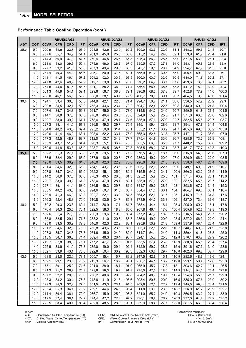
15/78 MODEL SELECTION
Performance Table Cooling Operation (cont.)
RHUE80AG2 RHUE100AG2 RHUE120AG2 RHUE140AG2ABT COT CCAP CFR CPD IPT CCAP CFR CPD IPT CCAP CFR CPD IPT CCAP CFR CPD IPT25,0 5,0 200,9 34,6 32,7 53,5 253,5 43,6 23,5 65,2 305,0 52,5 22,6 81,1 348,2 59,9 24,8 90,7
6,0 207,6 35,7 34,9 54,1 261,9 45,0 25,0 66,0 315,2 54,2 24,0 82,1 359,9 61,9 26,4 91,87,0 214,3 36,9 37,0 54,7 270,4 46,5 26,6 66,8 325,3 56,0 25,5 83,0 371,5 63,9 28,1 92,88,0 221,0 38,0 39,3 55,4 278,8 48,0 28,2 67,5 335,5 57,7 27,1 84,0 383,1 65,9 29,8 93,99,0 227,7 39,2 41,6 56,0 287,3 49,4 29,8 68,3 345,7 59,5 28,7 84,9 394,7 67,9 31,5 95,0
10,0 234,4 40,3 44,0 56,6 295,7 50,9 31,5 69,1 355,9 61,2 30,3 85,9 406,4 69,9 33,3 96,111,0 241,1 41,5 46,4 57,2 304,2 52,3 33,3 69,8 366,0 63,0 32,0 86,8 418,0 71,9 35,2 97,112,0 247,8 42,6 48,9 57,9 312,7 53,8 35,1 70,6 376,2 64,7 33,7 87,8 429,6 73,9 37,1 98,213,0 254,5 43,8 51,5 58,5 321,1 55,2 36,9 71,4 386,4 66,5 35,5 88,8 441,2 75,9 39,0 99,314,0 261,3 44,9 54,1 59,1 329,6 56,7 38,8 72,1 396,6 68,2 37,3 89,7 452,8 77,9 41,0 100,315,0 268,0 46,1 56,8 59,8 338,0 58,1 40,7 72,9 406,7 70,0 39,1 90,7 464,5 79,9 43,0 101,4
30,0 5,0 194,1 33,4 30,6 58,5 244,9 42,1 22,0 71,4 294,7 50,7 21,1 88,8 336,5 57,9 23,2 99,36,0 200,8 34,5 32,7 59,2 253,3 43,6 23,4 72,2 304,7 52,4 22,5 89,8 348,0 59,9 24,8 100,47,0 207,4 35,7 34,8 59,8 261,7 45,0 24,9 73,0 314,8 54,2 24,0 90,7 359,5 61,8 26,4 101,58,0 214,1 36,8 37,0 60,5 270,0 46,4 26,5 73,8 324,9 55,9 25,5 91,7 371,0 63,8 28,0 102,69,0 220,7 38,0 39,2 61,1 278,4 47,9 28,1 74,6 335,0 57,6 27,0 92,7 382,5 65,8 29,7 103,7
10,0 227,3 39,1 41,5 61,8 286,8 49,3 29,7 75,4 345,1 59,4 28,6 93,7 394,1 67,8 31,4 104,811,0 234,0 40,2 43,8 62,4 295,2 50,8 31,4 76,1 355,2 61,1 30,2 94,7 405,6 69,8 33,2 105,912,0 240,6 41,4 46,2 63,1 303,6 52,2 33,1 76,9 365,3 62,8 31,8 95,7 417,1 71,7 35,0 107,013,0 247,3 42,5 48,7 63,7 312,0 53,7 34,9 77,7 375,4 64,6 33,6 96,7 428,6 73,7 36,9 108,114,0 253,9 43,7 51,2 64,4 320,3 55,1 36,7 78,5 385,5 66,3 35,3 97,7 440,2 75,7 38,8 109,215,0 260,6 44,8 53,8 65,0 328,7 56,5 38,6 79,3 395,5 68,0 37,1 98,7 451,7 77,7 40,8 110,3
35,0 5,0 182,2 31,3 27,1 63,3 229,8 39,5 19,5 77,2 276,5 47,6 18,7 96,0 315,8 54,3 20,6 107,36,0 188,6 32,4 29,0 63,9 237,9 40,9 20,8 78,0 286,3 49,2 20,0 97,0 326,9 56,2 22,0 108,57,0 195,0 33,5 30,9 64,6 246,0 42,3 22,2 78,8 296,0 50,9 21,3 98,0 338,0 58,1 23,4 109,68,0 201,4 34,6 32,9 65,3 254,1 43,7 23,6 79,6 305,7 52,6 22,7 99,0 349,1 60,0 24,9 110,79,0 207,8 35,7 34,9 65,9 262,2 45,1 25,0 80,4 315,5 54,3 24,1 100,0 360,2 62,0 26,5 111,9
10,0 214,2 36,9 37,0 66,6 270,3 46,5 26,5 81,3 325,2 55,9 25,5 101,1 371,4 63,9 28,1 113,011,0 220,7 38,0 39,2 67,3 278,4 47,9 28,1 82,1 335,0 57,6 27,0 102,1 382,5 65,8 29,7 114,212,0 227,1 39,1 41,4 68,0 286,5 49,3 29,7 82,9 344,7 59,3 28,5 103,1 393,6 67,7 31,4 115,313,0 233,5 40,2 43,6 68,6 294,6 50,7 31,3 83,7 354,4 61,0 30,1 104,1 404,7 69,6 33,1 116,414,0 239,9 41,3 46,0 69,3 302,7 52,1 33,0 84,5 364,2 62,6 31,7 105,1 415,9 71,5 34,8 117,615,0 246,3 42,4 48,3 70,0 310,8 53,5 34,7 85,3 373,9 64,3 33,3 106,1 427,0 73,4 36,6 118,7
40,0 5,0 170,2 29,3 23,8 69,4 214,7 36,9 17,1 84,7 258,4 44,4 16,4 105,3 295,0 50,7 18,1 117,86,0 176,4 30,3 25,5 70,1 222,5 38,3 18,3 85,6 267,8 46,1 17,6 106,4 305,8 52,6 19,3 119,07,0 182,6 31,4 27,3 70,8 230,3 39,6 19,6 86,4 277,2 47,7 18,8 107,5 316,5 54,4 20,7 120,28,0 188,8 32,5 29,1 71,5 238,2 41,0 20,8 87,3 286,6 49,3 20,0 108,5 327,2 56,3 22,0 121,49,0 195,0 33,5 30,9 72,3 246,0 42,3 22,2 88,1 295,9 50,9 21,3 109,6 337,9 58,1 23,4 122,6
10,0 201,2 34,6 32,8 73,0 253,8 43,6 23,5 89,0 305,3 52,5 22,6 110,7 348,7 60,0 24,9 123,811,0 207,3 35,7 34,8 73,7 261,6 45,0 24,9 89,9 314,7 54,1 24,0 111,8 359,4 61,8 26,3 125,012,0 213,5 36,7 36,8 74,4 269,4 46,3 26,4 90,7 324,1 55,7 25,3 112,8 370,1 63,7 27,9 126,213,0 219,7 37,8 38,8 75,1 277,2 47,7 27,9 91,6 333,5 57,4 26,8 113,9 380,8 65,5 29,4 127,414,0 225,9 38,9 41,0 75,8 285,0 49,0 29,4 92,4 342,9 59,0 28,2 115,0 391,6 67,3 31,0 128,615,0 232,1 39,9 43,1 76,5 292,8 50,4 30,9 93,3 352,3 60,6 29,7 116,0 402,3 69,2 32,7 129,8
43,0 5,0 163,0 28,0 22,0 73,1 205,7 35,4 15,7 89,2 247,5 42,6 15,1 110,9 282,6 48,6 16,6 124,16,0 169,1 29,1 23,5 73,9 213,3 36,7 16,9 90,1 256,7 44,1 16,2 112,0 293,1 50,4 17,8 125,37,0 175,1 30,1 25,2 74,6 221,0 38,0 18,1 91,0 265,9 45,7 17,3 113,1 303,6 52,2 19,1 126,58,0 181,2 31,2 26,9 75,3 228,6 39,3 19,3 91,9 275,0 47,3 18,5 114,3 314,1 54,0 20,4 127,89,0 187,2 32,2 28,6 76,0 236,2 40,6 20,5 92,8 284,2 48,9 19,7 115,4 324,6 55,8 21,7 129,0
10,0 193,3 33,2 30,4 76,8 243,8 41,9 21,8 93,6 293,4 50,5 20,9 116,5 335,0 57,6 23,0 130,211,0 199,3 34,3 32,2 77,5 251,5 43,3 23,1 94,5 302,6 52,0 22,2 117,6 345,5 59,4 24,4 131,512,0 205,4 35,3 34,1 78,2 259,1 44,6 24,5 95,4 311,8 53,6 23,5 118,7 356,0 61,2 25,9 132,713,0 211,4 36,4 36,1 79,0 266,7 45,9 25,9 96,3 321,0 55,2 24,9 119,8 366,5 63,0 27,4 133,914,0 217,5 37,4 38,1 79,7 274,4 47,2 27,3 97,2 330,1 56,8 26,2 120,9 377,0 64,8 28,9 135,215,0 223,5 38,4 40,1 80,4 282,0 48,5 28,8 98,1 339,3 58,4 27,7 122,0 387,5 66,6 30,4 136,4
Where,ABT: Condenser Air Inlet Temperature (°C)COT: Chilled Water Outlet Temperature (°C)CAP: Cooling Capacity (kW)
CFR: Chilled Water Flow Rate at 5°C (m3/h)CPD: Water Cooler Pressure Drop (kPa)IPT: Compressor Input Power (kW)
Conversion Multiplier:1 kW = 860 kcal/h = 3412 Btu/h1 kPa = 0.102 mAq

MODEL SELECTION 15/79
Performance Table Cooling Operation (cont.)
RHUE160AG2 RHUE180AG2 RHUE210AG2 RHUE240AG2ABT COT CCAP CFR CPD IPT CCAP CFR CPD IPT CCAP CFR CPD IPT CCAP CFR CPD IPT
25,0 5,0 401,8 69,1 32,6 106,9 457,5 78,7 22,4 121,7 522,4 89,8 25,0 136,1 602,7 103,7 32,9 160,46,0 415,2 71,4 34,7 108,2 472,7 81,3 23,8 123,1 539,8 92,8 26,7 137,7 622,8 107,1 35,0 162,37,0 428,6 73,7 36,9 109,4 488,0 83,9 25,3 124,5 557,2 95,8 28,3 139,3 643,0 110,6 37,2 164,28,0 442,1 76,0 39,1 110,7 503,3 86,6 26,9 126,0 574,7 98,8 30,0 140,9 663,1 114,0 39,5 166,19,0 455,5 78,3 41,4 112,0 518,5 89,2 28,4 127,4 592,1 101,8 31,8 142,5 683,2 117,5 41,8 168,0
10,0 468,9 80,6 43,8 113,2 533,8 91,8 30,1 128,8 609,5 104,8 33,6 144,1 703,3 121,0 44,2 169,811,0 482,3 83,0 46,2 114,5 549,1 94,4 31,7 130,3 627,0 107,8 35,5 145,7 723,4 124,4 46,7 171,712,0 495,7 85,3 48,7 115,8 564,3 97,1 33,4 131,7 644,4 110,8 37,4 147,3 743,5 127,9 49,2 173,613,0 509,1 87,6 51,3 117,0 579,6 99,7 35,2 133,1 661,8 113,8 39,4 148,9 763,6 131,3 51,7 175,514,0 522,5 89,9 53,9 118,3 594,9 102,3 37,0 134,6 679,3 116,8 41,4 150,5 783,8 134,8 54,4 177,415,0 535,9 92,2 56,6 119,5 610,1 104,9 38,8 136,0 696,7 119,8 43,4 152,1 803,9 138,3 57,1 179,3
30,0 5,0 388,2 66,8 30,5 117,0 442,0 76,0 21,0 133,2 504,7 86,8 23,4 148,9 582,3 100,2 30,8 175,56,0 401,5 69,1 32,6 118,3 457,1 78,6 22,3 134,6 522,0 89,8 25,0 150,6 602,3 103,6 32,9 177,57,0 414,8 71,3 34,7 119,6 472,3 81,2 23,8 136,1 539,3 92,8 26,6 152,2 622,2 107,0 35,0 179,58,0 428,1 73,6 36,8 120,9 487,4 83,8 25,3 137,6 556,5 95,7 28,3 153,9 642,2 110,5 37,1 181,49,0 441,4 75,9 39,0 122,2 502,5 86,4 26,8 139,1 573,8 98,7 30,0 155,5 662,1 113,9 39,4 183,4
10,0 454,7 78,2 41,3 123,5 517,7 89,0 28,3 140,6 591,1 101,7 31,7 157,2 682,0 117,3 41,7 185,311,0 468,0 80,5 43,7 124,8 532,8 91,6 29,9 142,0 608,4 104,6 33,5 158,9 702,0 120,7 44,0 187,312,0 481,3 82,8 46,1 126,2 547,9 94,2 31,6 143,5 625,7 107,6 35,3 160,5 721,9 124,2 46,5 189,213,0 494,6 85,1 48,5 127,5 563,1 96,8 33,3 145,0 642,9 110,6 37,2 162,2 741,9 127,6 49,0 191,214,0 507,9 87,4 51,0 128,8 578,2 99,4 35,0 146,5 660,2 113,6 39,2 163,8 761,8 131,0 51,5 193,115,0 521,2 89,6 53,6 130,1 593,3 102,1 36,8 148,0 677,5 116,5 41,2 165,5 781,7 134,5 54,1 195,1
35,0 5,0 364,3 62,7 27,0 126,5 414,8 71,3 18,6 143,9 473,6 81,5 20,8 161,0 546,5 94,0 27,3 189,86,0 377,2 64,9 28,9 127,9 429,4 73,9 19,8 145,5 490,3 84,3 22,2 162,7 565,8 97,3 29,2 191,87,0 390,0 67,1 30,8 129,2 444,0 76,4 21,1 147,0 507,0 87,2 23,6 164,4 585,0 100,6 31,1 193,88,0 402,8 69,3 32,8 130,5 458,6 78,9 22,5 148,5 523,7 90,1 25,1 166,1 604,2 103,9 33,1 195,89,0 415,7 71,5 34,8 131,9 473,2 81,4 23,9 150,1 540,4 92,9 26,7 167,8 623,5 107,2 35,1 197,8
10,0 428,5 73,7 36,9 133,2 487,8 83,9 25,3 151,6 557,0 95,8 28,3 169,5 642,7 110,6 37,2 199,811,0 441,3 75,9 39,0 134,6 502,4 86,4 26,8 153,1 573,7 98,7 29,9 171,2 662,0 113,9 39,4 201,912,0 454,2 78,1 41,2 135,9 517,1 88,9 28,3 154,6 590,4 101,6 31,6 172,9 681,2 117,2 41,6 203,913,0 467,0 80,3 43,5 137,3 531,7 91,4 29,8 156,2 607,1 104,4 33,4 174,6 700,5 120,5 43,9 205,914,0 479,8 82,5 45,8 138,6 546,3 94,0 31,4 157,7 623,8 107,3 35,1 176,4 719,7 123,8 46,2 207,915,0 492,7 84,7 48,2 139,9 560,9 96,5 33,0 159,2 640,5 110,2 37,0 178,1 739,0 127,1 48,6 209,9
40,0 5,0 340,4 58,6 23,8 138,9 387,6 66,7 16,3 158,0 442,6 76,1 18,2 176,7 510,7 87,8 24,0 208,36,0 352,8 60,7 25,4 140,3 401,7 69,1 17,4 159,6 458,7 78,9 19,5 178,5 529,2 91,0 25,7 210,47,0 365,2 62,8 27,2 141,7 415,7 71,5 18,6 161,2 474,7 81,7 20,8 180,3 547,8 94,2 27,4 212,58,0 377,6 64,9 29,0 143,1 429,8 73,9 19,9 162,8 490,8 84,4 22,2 182,1 566,3 97,4 29,2 214,69,0 389,9 67,1 30,8 144,5 443,9 76,4 21,1 164,4 506,9 87,2 23,6 183,9 584,9 100,6 31,1 216,8
10,0 402,3 69,2 32,7 145,9 458,0 78,8 22,4 166,0 523,0 90,0 25,1 185,7 603,5 103,8 33,0 218,911,0 414,7 71,3 34,6 147,3 472,1 81,2 23,8 167,6 539,1 92,7 26,6 187,5 622,0 107,0 34,9 221,012,0 427,1 73,5 36,6 148,7 486,2 83,6 25,1 169,2 555,2 95,5 28,1 189,3 640,6 110,2 37,0 223,113,0 439,4 75,6 38,7 150,2 500,3 86,0 26,5 170,8 571,3 98,3 29,7 191,1 659,1 113,4 39,0 225,214,0 451,8 77,7 40,8 151,6 514,4 88,5 28,0 172,5 587,3 101,0 31,3 192,9 677,7 116,6 41,2 227,415,0 464,2 79,8 43,0 153,0 528,4 90,9 29,5 174,1 603,4 103,8 33,0 194,7 696,3 119,8 43,4 229,5
43,0 5,0 326,1 56,1 21,9 146,3 371,3 63,9 15,0 166,4 423,9 72,9 16,8 186,1 489,1 84,1 22,1 219,46,0 338,2 58,2 23,5 147,7 385,0 66,2 16,1 168,1 439,7 75,6 18,0 188,0 507,3 87,3 23,7 221,67,0 350,3 60,3 25,1 149,2 398,8 68,6 17,2 169,7 455,4 78,3 19,3 189,8 525,4 90,4 25,3 223,88,0 362,4 62,3 26,8 150,6 412,6 71,0 18,4 171,4 471,1 81,0 20,5 191,7 543,6 93,5 27,0 225,99,0 374,5 64,4 28,5 152,1 426,3 73,3 19,6 173,0 486,8 83,7 21,9 193,5 561,7 96,6 28,8 228,1
10,0 386,6 66,5 30,3 153,5 440,1 75,7 20,8 174,7 502,6 86,4 23,2 195,4 579,9 99,7 30,6 230,311,0 398,7 68,6 32,1 155,0 453,9 78,1 22,0 176,3 518,3 89,1 24,7 197,2 598,0 102,9 32,4 232,512,0 410,8 70,7 34,0 156,4 467,7 80,4 23,3 178,0 534,0 91,9 26,1 199,1 616,2 106,0 34,3 234,713,0 422,9 72,7 36,0 157,9 481,4 82,8 24,7 179,7 549,7 94,6 27,6 200,9 634,3 109,1 36,3 236,914,0 435,0 74,8 38,0 159,4 495,2 85,2 26,0 181,3 565,5 97,3 29,1 202,8 652,5 112,2 38,3 239,015,0 447,1 76,9 40,0 160,8 509,0 87,5 27,4 183,0 581,2 100,0 30,7 204,6 670,6 115,3 40,4 241,2
Where,ABT: Condenser Air Inlet Temperature (°C)COT: Chilled Water Outlet Temperature (°C)CAP: Cooling Capacity (kW)
CFR: Chilled Water Flow Rate at 5°C (m3/h)CPD: Water Cooler Pressure Drop (kPa)IPT: Compressor Input Power (kW)
Conversion Multiplier:1 kW = 860 kcal/h = 3412 Btu/h1 kPa = 0.102 mAq

15/80 MODEL SELECTION
15.3. PERFORMANCE TABLE (HEATING OPERATION)
RHUE40AG2 RHUE50AG2 RHUE60AG2 RHUE70AG2ABTW HOT HCAP HFR CPD IPT HCAP HFR CPD IPT HCAP HFR CPD IPT HCAP HFR CPD IPT15,0 35,0 135,9 23,4 31,7 32,7 156,9 27,0 35,4 35,2 187,8 32,3 33,6 43,6 228,6 39,3 41,9 53,6
40,0 135,4 23,3 31,4 35,3 156,3 26,9 35,1 38,0 187,1 32,2 33,4 47,0 227,7 39,2 41,6 57,845,0 134,8 23,2 31,2 39,4 155,7 26,8 34,8 42,4 186,3 32,0 33,1 52,4 226,7 39,0 41,3 64,550,0 134,3 23,1 30,9 45,0 155,0 26,7 34,5 48,4 185,5 31,9 32,8 59,9 225,8 38,8 40,9 73,655,0 133,7 23,0 30,7 52,1 154,4 26,6 34,3 56,0 184,7 31,8 32,6 69,3 224,9 38,7 40,6 85,2
10,0 35,0 123,3 21,2 26,3 32,2 142,4 24,5 29,4 34,7 170,4 29,3 27,9 42,9 207,4 35,7 34,8 52,740,0 122,2 21,0 25,8 34,8 141,1 24,3 28,8 37,5 168,8 29,0 27,4 46,4 205,5 35,3 34,2 57,045,0 121,0 20,8 25,4 38,8 139,7 24,0 28,3 41,7 167,2 28,8 26,9 51,6 203,6 35,0 33,6 63,550,0 119,9 20,6 24,9 44,1 138,4 23,8 27,8 47,4 165,7 28,5 26,4 58,7 201,6 34,7 33,0 72,255,0 118,7 20,4 24,5 50,8 137,1 23,6 27,3 54,6 164,1 28,2 26,0 67,6 199,7 34,3 32,4 83,1
6,0 45,0 110,0 18,9 21,1 38,3 127,0 21,8 23,6 41,2 152,0 26,1 22,4 51,0 185,0 31,8 28,0 62,75,0 35,0 110,7 19,0 21,4 31,7 127,8 22,0 23,9 34,1 153,0 26,3 22,7 42,2 186,2 32,0 28,3 51,9
40,0 109,0 18,7 20,8 34,3 125,8 21,6 23,2 36,9 150,6 25,9 22,0 45,7 183,3 31,5 27,5 56,245,0 107,2 18,4 20,1 38,2 123,8 21,3 22,5 41,1 148,2 25,5 21,4 50,8 180,4 31,0 26,6 62,550,0 105,5 18,1 19,5 43,2 121,8 21,0 21,8 46,5 145,8 25,1 20,7 57,6 177,5 30,5 25,8 70,855,0 103,8 17,9 18,9 49,5 119,8 20,6 21,1 53,2 143,4 24,7 20,1 65,9 174,6 30,0 25,0 81,0
0 35,0 98,1 16,9 17,0 31,2 113,2 19,5 18,9 33,5 135,5 23,3 18,0 41,5 164,9 28,4 22,4 51,040,0 95,8 16,5 16,2 33,8 110,6 19,0 18,1 36,4 132,3 22,8 17,2 45,1 161,1 27,7 21,4 55,445,0 93,5 16,1 15,5 37,6 107,9 18,6 17,3 40,4 129,1 22,2 16,4 50,0 157,2 27,0 20,5 61,550,0 91,1 15,7 14,8 42,4 105,2 18,1 16,5 45,6 126,0 21,7 15,7 56,4 153,3 26,4 19,5 69,355,0 88,8 15,3 14,0 48,2 102,6 17,6 15,7 51,8 122,8 21,1 14,9 64,2 149,4 25,7 18,6 78,9
-5 35,0 85,4 14,7 13,0 30,6 98,7 17,0 14,6 33,0 118,1 20,3 13,8 40,8 143,7 24,7 17,2 50,140,0 82,6 14,2 12,2 33,4 95,3 16,4 13,6 35,9 114,1 19,6 13,0 44,4 138,8 23,9 16,1 54,645,0 79,7 13,7 11,4 37,0 92,0 15,8 12,7 39,8 110,1 18,9 12,1 49,2 134,0 23,0 15,1 60,550,0 76,8 13,2 10,6 41,5 88,6 15,2 11,9 44,6 106,1 18,2 11,3 55,2 129,1 22,2 14,1 67,955,0 73,9 12,7 9,9 46,9 85,3 14,7 11,0 50,4 102,1 17,6 10,5 62,4 124,3 21,4 13,1 76,8
-10 35,0 72,8 12,5 9,6 30,1 84,1 14,5 10,7 32,4 100,6 17,3 10,2 40,1 122,5 21,1 12,7 49,340,0 69,4 11,9 8,7 32,9 80,1 13,8 9,8 35,4 95,8 16,5 9,3 43,8 116,6 20,1 11,6 53,845,0 65,9 11,3 7,9 36,4 76,1 13,1 8,9 39,1 91,0 15,7 8,4 48,4 110,8 19,1 10,5 59,550,0 62,4 10,7 7,1 40,6 72,1 12,4 8,0 43,7 86,2 14,8 7,6 54,1 105,0 18,1 9,5 66,555,0 58,9 10,1 6,4 45,6 68,0 11,7 7,2 49,1 81,4 14,0 6,8 60,7 99,1 17,0 8,5 74,7
-15 35,0 54,2 9,3 5,5 29,6 62,6 10,8 6,1 31,8 74,9 12,9 5,8 39,4 91,1 15,7 7,2 48,440,0 50,5 8,7 4,8 32,4 58,3 10,0 5,3 34,8 69,8 12,0 5,1 43,1 85,0 14,6 6,3 53,045,0 46,9 8,1 4,1 35,8 54,1 9,3 4,6 38,5 64,8 11,1 4,4 47,6 78,9 13,6 5,5 58,550,0 43,2 7,4 3,5 39,7 49,9 8,6 4,0 42,7 59,7 10,3 3,8 52,9 72,7 12,5 4,7 65,155,0 39,6 6,8 3,0 44,3 45,7 7,9 3,3 47,7 54,7 9,4 3,2 59,0 66,6 11,5 4,0 72,5
Where,ABT: Condenser Air Inlet Temperature (°C)COT: Chilled Water Outlet Temperature (°C)CAP: Cooling Capacity (kW)
CFR: Chilled Water Flow Rate at 5°C (m3/h)CPD: Water Cooler Pressure Drop (kPa)IPT: Compressor Input Power (kW)
Conversion Multiplier:1 kW = 860 kcal/h = 3412 Btu/h1 kPa = 0.102 mAq

MODEL SELECTION 15/81
Performance Table Heating Operation (cont.)
RHUE80AG2 RHUE100AG2 RHUE120AG2 RHUE140AG2ABTW HOT HCAP HFR CPD IPT HCAP HFR CPD IPT HCAP HFR CPD IPT HCAP HFR CPD IPT15,0 35,0 228,6 39,3 41,9 53,6 313,9 54,0 35,3 70,4 376,9 64,8 33,8 87,2 458,5 78,9 42,0 107,3
40,0 227,7 39,2 41,6 57,8 312,6 53,8 35,1 76,0 375,4 64,6 33,5 94,0 456,6 78,5 41,6 115,745,0 226,7 39,0 41,3 64,5 311,3 53,5 34,8 84,7 373,8 64,3 33,3 104,9 454,7 78,2 41,3 129,150,0 225,8 38,8 40,9 73,6 310,0 53,3 34,5 96,8 372,3 64,0 33,0 119,8 452,8 77,9 41,0 147,455,0 224,9 38,7 40,6 85,2 308,7 53,1 34,2 112,0 370,7 63,8 32,8 138,6 450,9 77,6 40,7 170,6
10,0 35,0 207,4 35,7 34,8 52,7 284,7 49,0 29,3 69,3 341,9 58,8 28,1 85,8 415,9 71,5 34,8 105,640,0 205,5 35,3 34,2 57,0 282,1 48,5 28,8 74,9 338,7 58,3 27,6 92,7 412,1 70,9 34,2 114,145,0 203,6 35,0 33,6 63,5 279,5 48,1 28,3 83,4 335,6 57,7 27,1 103,3 408,2 70,2 33,6 127,150,0 201,6 34,7 33,0 72,2 276,8 47,6 27,8 94,9 332,4 57,2 26,6 117,4 404,3 69,5 33,0 144,555,0 199,7 34,3 32,4 83,1 274,2 47,2 27,3 109,2 329,3 56,6 26,1 135,2 400,5 68,9 32,4 166,4
6,0 45,0 185,0 31,8 28,0 62,7 254,0 43,7 23,6 82,4 305,0 52,5 102,0 102,0 371,0 63,8 28,0 125,55,0 35,0 186,2 32,0 28,3 51,9 255,6 44,0 23,9 68,2 306,9 52,8 22,8 84,4 373,3 64,2 28,3 103,8
40,0 183,3 31,5 27,5 56,2 251,6 43,3 23,2 73,9 302,1 52,0 22,2 91,4 367,5 63,2 27,5 112,545,0 180,4 31,0 26,6 62,5 247,6 42,6 22,5 82,1 297,4 51,1 21,5 101,7 361,7 62,2 26,7 125,150,0 177,5 30,5 25,8 70,8 243,7 41,9 21,8 93,0 292,6 50,3 20,8 115,1 355,9 61,2 25,9 141,655,0 174,6 30,0 25,0 81,0 239,7 41,2 21,1 106,4 287,8 49,5 20,2 131,8 350,1 60,2 25,1 162,1
0 35,0 164,9 28,4 22,4 51,0 226,5 38,9 18,9 67,0 271,9 46,8 18,1 83,0 330,8 56,9 22,5 102,140,0 161,1 27,7 21,4 55,4 221,1 38,0 18,1 72,8 265,5 45,7 17,3 90,1 323,0 55,6 21,5 110,945,0 157,2 27,0 20,5 61,5 215,8 37,1 17,3 80,8 259,1 44,6 16,5 100,1 315,2 54,2 20,5 123,150,0 153,3 26,4 19,5 69,3 210,5 36,2 16,5 91,1 252,7 43,5 15,7 112,8 307,4 52,9 19,5 138,855,0 149,4 25,7 18,6 78,9 205,1 35,3 15,7 103,7 246,3 42,4 15,0 128,3 299,6 51,5 18,6 157,9
-5 35,0 143,7 24,7 17,2 50,1 197,3 33,9 14,5 65,9 236,9 40,8 13,9 81,6 288,2 49,6 17,3 100,440,0 138,8 23,9 16,1 54,6 190,6 32,8 13,6 71,8 228,9 39,4 13,0 88,8 278,4 47,9 16,2 109,345,0 134,0 23,0 15,1 60,5 184,0 31,6 12,7 79,5 220,9 38,0 12,2 98,5 268,7 46,2 15,1 121,150,0 129,1 22,2 14,1 67,9 177,3 30,5 11,9 89,2 212,9 36,6 11,3 110,5 259,0 44,5 14,1 135,955,0 124,3 21,4 13,1 76,8 170,6 29,3 11,0 100,9 204,9 35,2 10,5 124,9 249,2 42,9 13,1 153,7
-10 35,0 122,5 21,1 12,7 49,3 168,2 28,9 10,7 64,8 201,9 34,7 10,3 80,2 245,6 42,2 12,7 98,640,0 116,6 20,1 11,6 53,8 160,1 27,5 9,8 70,7 192,3 33,1 9,3 87,5 233,9 40,2 11,6 107,745,0 110,8 19,1 10,5 59,5 152,1 26,2 8,8 78,2 182,7 31,4 8,5 96,8 222,2 38,2 10,5 119,250,0 105,0 18,1 9,5 66,5 144,1 24,8 8,0 87,4 173,0 29,8 7,6 108,2 210,5 36,2 9,5 133,155,0 99,1 17,0 8,5 74,7 136,1 23,4 7,1 98,1 163,4 28,1 6,8 121,4 198,8 34,2 8,5 149,4
-15 35,0 101,3 17,4 8,8 48,4 139,0 23,9 7,4 63,6 166,9 28,7 7,1 78,8 203,1 34,9 8,8 96,940,0 94,4 16,2 7,7 53,0 129,7 22,3 6,5 69,6 155,7 26,8 6,2 86,2 189,4 32,6 7,7 106,145,0 87,6 15,1 6,7 58,5 120,3 20,7 5,6 76,9 144,4 24,8 5,4 95,2 175,7 30,2 6,7 117,250,0 80,8 13,9 5,7 65,1 110,9 19,1 4,8 85,5 133,2 22,9 4,6 105,8 162,0 27,9 5,7 130,255,0 74,0 12,7 4,8 72,5 101,6 17,5 4,1 95,3 122,0 21,0 3,9 118,0 148,3 25,5 4,9 145,2
Where,ABT: Condenser Air Inlet Temperature (°C)COT: Chilled Water Outlet Temperature (°C)CAP: Cooling Capacity (kW)
CFR: Chilled Water Flow Rate at 5°C (m3/h)CPD: Water Cooler Pressure Drop (kPa)IPT: Compressor Input Power (kW)
Conversion Multiplier:1 kW = 860 kcal/h = 3412 Btu/h1 kPa = 0.102 mAq

15/82 MODEL SELECTION
Performance Table Heating Operation (cont.)
RHUE160AG2 RHUE180AG2 RHUE210AG2 RHUE240AG2ABTW HOT HCAP HFR CPD IPT HCAP HFR CPD IPT HCAP HFR CPD IPT HCAP HFR CPD IPT15,0 35,0 458,5 78,9 42,0 107,3 564,8 97,1 33,5 130,6 687,1 118,2 42,3 160,9 687,1 118,2 42,3 160,9
40,0 456,6 78,5 41,6 115,7 562,4 96,7 33,2 140,9 684,3 117,7 41,9 173,5 684,3 117,7 41,9 173,545,0 454,7 78,2 41,3 129,1 560,1 96,3 33,0 157,1 681,4 117,2 41,6 193,5 681,4 117,2 41,6 193,550,0 452,8 77,9 41,0 147,4 557,8 95,9 32,7 179,4 678,6 116,7 41,3 221,0 678,6 116,7 41,3 221,055,0 450,9 77,6 40,7 170,6 555,5 95,5 32,4 207,7 675,8 116,2 41,0 255,8 675,8 116,2 41,0 255,8
10,0 35,0 415,9 71,5 34,8 105,6 512,3 88,1 27,8 128,5 623,3 107,2 35,1 158,3 623,3 107,2 35,1 158,340,0 412,1 70,9 34,2 114,1 507,6 87,3 27,3 138,9 617,5 106,2 34,5 171,1 617,5 106,2 34,5 171,145,0 408,2 70,2 33,6 127,1 502,8 86,5 26,8 154,7 611,8 105,2 33,9 190,6 611,8 105,2 33,9 190,650,0 404,3 69,5 33,0 144,5 498,1 85,7 26,3 175,9 606,0 104,2 33,2 216,7 606,0 104,2 33,2 216,755,0 400,5 68,9 32,4 166,4 493,3 84,9 25,9 202,5 600,2 103,2 32,6 249,5 600,2 103,2 32,6 249,5
6,0 45,0 371,0 63,8 28,0 125,5 457,0 78,6 22,3 152,8 556,0 95,6 28,2 188,2 556,0 95,6 28,2 188,25,0 35,0 373,3 64,2 28,3 103,8 459,9 79,1 22,6 126,4 559,5 96,2 28,5 155,7 559,5 96,2 28,5 155,7
40,0 367,5 63,2 27,5 112,5 452,7 77,9 21,9 137,0 550,8 94,7 27,7 168,7 550,8 94,7 27,7 168,745,0 361,7 62,2 26,7 125,1 445,5 76,6 21,3 152,3 542,1 93,2 26,9 187,6 542,1 93,2 26,9 187,650,0 355,9 61,2 25,9 141,6 438,4 75,4 20,6 172,5 533,3 91,7 26,0 212,4 533,3 91,7 26,0 212,455,0 350,1 60,2 25,1 162,1 431,2 74,2 20,0 197,4 524,6 90,2 25,2 243,1 524,6 90,2 25,2 243,1
0 35,0 330,8 56,9 22,5 102,1 407,4 70,1 17,9 124,3 495,7 85,3 22,6 153,1 495,7 85,3 22,6 153,140,0 323,0 55,6 21,5 110,9 397,8 68,4 17,1 135,0 484,0 83,3 21,6 166,3 484,0 83,3 21,6 166,345,0 315,2 54,2 20,5 123,1 388,3 66,8 16,4 149,9 472,4 81,2 20,6 184,6 472,4 81,2 20,6 184,650,0 307,4 52,9 19,5 138,8 378,7 65,1 15,6 169,0 460,7 79,2 19,7 208,1 460,7 79,2 19,7 208,155,0 299,6 51,5 18,6 157,9 369,1 63,5 14,8 192,2 449,1 77,2 18,7 236,8 449,1 77,2 18,7 236,8
-5 35,0 288,2 49,6 17,3 100,4 355,0 61,1 13,8 122,2 431,9 74,3 17,4 150,5 431,9 74,3 17,4 150,540,0 278,4 47,9 16,2 109,3 343,0 59,0 12,9 133,1 417,3 71,8 16,3 163,9 417,3 71,8 16,3 163,945,0 268,7 46,2 15,1 121,1 331,0 56,9 12,1 147,5 402,7 69,3 15,2 181,7 402,7 69,3 15,2 181,750,0 259,0 44,5 14,1 135,9 319,0 54,9 11,2 165,5 388,1 66,7 14,2 203,8 388,1 66,7 14,2 203,855,0 249,2 42,9 13,1 153,7 307,0 52,8 10,4 187,1 373,5 64,2 13,2 230,4 373,5 64,2 13,2 230,4
-10 35,0 245,6 42,2 12,7 98,6 302,6 52,0 10,1 120,1 368,1 63,3 12,8 147,9 368,1 63,3 12,8 147,940,0 233,9 40,2 11,6 107,7 288,1 49,6 9,2 131,1 350,5 60,3 11,7 161,5 350,5 60,3 11,7 161,545,0 222,2 38,2 10,5 119,2 273,7 47,1 8,4 145,1 333,0 57,3 10,6 178,7 333,0 57,3 10,6 178,750,0 210,5 36,2 9,5 133,1 259,3 44,6 7,6 162,0 315,4 54,3 9,5 199,6 315,4 54,3 9,5 199,655,0 198,8 34,2 8,5 149,4 244,9 42,1 6,8 181,9 297,9 51,2 8,6 224,1 297,9 51,2 8,6 224,1
-15 35,0 203,1 34,9 8,8 96,9 250,1 43,0 7,1 118,0 304,3 52,3 8,9 145,3 304,3 52,3 8,9 145,340,0 189,4 32,6 7,7 106,1 233,3 40,1 6,2 129,2 283,8 48,8 7,8 159,1 283,8 48,8 7,8 159,145,0 175,7 30,2 6,7 117,2 216,4 37,2 5,3 142,7 263,3 45,3 6,8 175,7 263,3 45,3 6,8 175,750,0 162,0 27,9 5,7 130,2 199,6 34,3 4,6 158,5 242,8 41,8 5,8 195,3 242,8 41,8 5,8 195,355,0 148,3 25,5 4,9 145,2 182,7 31,4 3,9 176,8 222,3 38,2 4,9 217,7 222,3 38,2 4,9 217,7
Where,ABT: Condenser Air Inlet Temperature (°C)COT: Chilled Water Outlet Temperature (°C)CAP: Cooling Capacity (kW)
CFR: Chilled Water Flow Rate at 5°C (m3/h)CPD: Water Cooler Pressure Drop (kPa)IPT: Compressor Input Power (kW)
Conversion Multiplier:1 kW = 860 kcal/h = 3412 Btu/h1 kPa = 0.102 mAq

MODEL SELECTION 15/83
15.4. ELECTRICAL DATA
Commpressor Motor Air Side HeatExchanger
CoolingOperation
HeatingOperation Fan Motor
Unit MainPower
ApplicableInstantaneous
Voltage (V)
MaximumUnit
Current
STC*2Unit
MaximumModel
(V) (Hz) Maximum MinimumSTC*1
(A)RNC(A)
IPT(kW)
RNC(A)
IPT(kW)
RNC(A)
IPT(kW) (A) (A)
380 50 418 342 114 59,4 34,0 66,9 38,3 4,9 2,4 95 114RHUE 40AG2
415 50 457 374 125 54,4 34,0 61,2 38,3 4,9 2,4 88 125380 50 418 342 114 68,8 39,4 72,0 41,2 7,2 3,3 104 114
RHUE 50AG2415 50 457 374 125 63,0 39,4 65,9 41,2 7,2 3,3 96 125380 50 418 342 148 85,6 49,0 89,1 51,0 7,2 3,3 127 148
RHUE 60AG2415 50 457 374 161 78,4 49,0 81,6 51,0 7,2 3,3 117 161380 50 418 342 178 95,7 54,8 109,5 62,7 10,8 5,0 159 178
RHUE 70AG2415 50 457 374 195 87,6 54,8 100,3 62,7 10,8 5,0 146 195380 50 418 342 178 112,8 64,6 109,5 62,7 10,8 5,0 159 178
RHUE 80AG2415 50 457 374 195 103,3 64,6 100,3 62,7 10,8 5,0 146 195380 50 418 342 114 137,6 78,8 143,9 82,4 14,4 6,6 209 134
RHUE100AG2415 50 457 374 125 126,0 78,8 131,8 82,4 14,4 6,6 192 143380 50 418 342 148 171,1 98,0 178,1 102,0 14,4 6,6 255 173
RHUE120AG2415 50 457 374 161 156,7 98,0 163,1 102,0 14,4 6,6 235 184380 50 418 342 178 191,4 109,6 219,2 125,5 21,6 10,0 317 206
RHUE140AG2415 50 457 374 195 175,3 109,6 200,7 125,5 21,6 10,0 293 220380 50 418 342 178 225,6 129,2 219,2 125,5 21,6 10,0 317 211
RHUE160AG2415 50 457 374 195 206,6 129,2 200,7 125,5 21,6 10,0 293 225380 50 418 342 148 256,7 147,0 265,5 152,8 21,6 10,0 380 185
RHUE180AG2415 50 457 374 161 235,1 147,0 243,1 152,8 21,6 10,0 350 195380 50 418 342 178 287,1 164,4 328,7 188,2 32,4 15,0 476 220
RHUE210AG2415 50 457 374 195 262,9 164,4 301,0 188,2 32,4 15,0 439 233380 50 418 342 178 338,5 193,8 328,7 188,2 32,4 15,0 476 243
RHUE240AG2415 50 457 374 195 309,9 193,8 301,0 188,2 32,4 15,0 439 255
NOTE:
1. This data is based on the following conditionsCooling Operation : Chilled Water Inlet/Outlet Temperature: 12/7�, Ambient Temperature: 35�.Heating Operation : Hot Water Inlet/Outlet Temperature 40/45�, Ambient Temperature 6�(WB)
2. The "Maximum Unit Current" shown in the above table is the maximum total unit running current at the followingconditions.Supply Voltage: 90% of the rated voltage, Unit Capacity: 100% at max. operating conditions
3, The power supply cables must be sized to cover this maximum current value.4. Starting Current (*1,*2) means as follows.
*1:First Compressor Starting Current*2:Unit Maximum Starting Current, when Last Compressor starts.
5. Compressor motor is star-delta starting
VOL: Rated Unit Supply Voltage(V) RNC: Running Current(A)STC: Starting Current(A) IPT: Input(kW)Hz: Frequency(Hz)

15/84 MODEL SELECTION
15.5. SOUND DATA
Standard Models
Sound Power Level (dB)Frequency Band (Hz) OverallModel
63 125 250 500 1000 2000 4000 8000
RHUE40AG2 89 87 82 77 80 72 62 57 82RHUE50AG2 91 89 84 79 80 72 63 59 83RHUE60AG2 91 89 84 79 82 74 64 59 84RHUE70AG2 92 90 85 83 81 74 64 60 85RHUE80AG2 92 90 85 83 81 74 64 60 85
RHUE100AG2 94 92 87 82 83 75 66 62 86RHUE120AG2 94 92 87 82 85 77 67 62 87RHUE140AG2 95 93 88 86 84 77 67 63 88RHUE160AG2 95 93 88 86 84 77 67 63 88RHUE180AG2 96 94 89 87 85 78 68 64 89RHUE210AG2 98 96 91 89 87 80 70 66 91RHUE240AG2 98 96 91 89 87 80 70 66 91
Low Noise Option
Sound Power Level (dB)Frequency Band (Hz)Model
63 125 250 500 1000 2000 4000 8000Overall
RHUE40AG2 87 85 80 75 78 70 60 55 80RHUE50AG2 89 87 82 77 78 70 61 57 81RHUE60AG2 89 87 82 77 80 72 62 57 82RHUE70AG2 90 88 83 81 79 72 62 58 83RHUE80AG2 90 88 83 81 79 72 62 58 83
RHUE100AG2 92 90 85 80 81 73 64 60 84RHUE120AG2 92 90 85 78 83 75 65 60 85RHUE140AG2 93 91 86 84 82 75 65 61 86RHUE160AG2 93 91 86 84 82 75 65 61 86RHUE180AG2 94 92 87 85 83 76 66 62 87RHUE210AG2 96 94 89 87 85 78 68 64 89RHUE240AG2 96 94 89 87 85 78 68 64 89
NOTE:1. Operating conditions are as follows:
Water Inlet/Outlet Temperature 12/7 °C, Ambient Temperature 35 °C, All Fans Running

APPLICATION DATA 16/85
16. APPLICATION DATA
16.1. WORKING RANGE
Working Range
Item For Cooling Operation For Heating Operation RemarkWorking Voltage 90% ~ 110% of Rated Voltage
Voltage Imbalance Within ±3% Deviation from Each Voltage atCompressor TerminalsPower Supply
Starting Voltage Higher than 85% of Rated Voltage
Ambient Temperature -15 ~ 46°C -9.5 ~ 21 °C DB-10 ~ 15.5 °C WB
Standard 5 ~ 15°C 35 ~ 55°C WaterWater OutletTemperature Low Temperature
Option
4 ~ 0°C (Low 1)-1 ~ -5°C (Low2)-6 ~ -10°C (Low3)
Ethylene glycol
Maximum Permissible Water Pressure 1.0 MPa
Water Side Working Range
MODEL RHUE AG2 40 50 60 70 80 100 120 140 160 180 210 240
m3/h 12.0 13.9 16.6 19.0 21.9 27.7 33.3 37.9 44.0 49.9 56.9 65.9Water Flow Range
m3/h 32.2 37.4 44.8 51.1 59.1 74.6 89.7 102 118 134 153 178
MinimumInternal Water Volume m3 0.31 0.36 0.43 0.49 0.57 0.71 0.86 0.98 1.13 1.28 1.46 1.70
Internal Volume inWater Side Heat Exchanger Liter 15.1 16.7 21.5 23.9 23.9 33.4 43.0 47.8 47.8 64.5 71.7 71.7
NOTE:1. Minimum Internal Water Volume above table is for
standard ON/OFF differential.In case of changing ON/OFF differential, minimuminternal water volume changes as followingpercentage.
Inlet ON/OFF Differential(set by Dip-switch 5, 3&4pins) 4°C 3°C 2°C 1°C
Minimum Internal WaterVolume 50% 67% 100% 200%
2. To prevent frequent ON/OFF for no load or extremelylow load operation, system internal water volumeshall be more than above table.ON/OFF cycles shall be maximum 6 times per hour.(minimum 5 minutes operation and minimum 5minutes thermostat OFF)

16/86 APPLICATION DATA
16.2. PART LOAD PERFORMANCE
Model: RHUE40AG2~ RHUE240AG2
Compressor LoadAmbient
Temperature Performance 15~99% Full Load
Capacity % 18 20 30 40 50 60 70 80 89
Input % 38 39 46 53 61 71 84 99 11643゚ C
COP % 47 51 65 75 82 85 83 81 77
Capacity % 19 20 30 40 50 60 70 80 90 94
Input % 36 36 42 50 57 63 74 87 102 11040゚ C
COP % 53 56 71 80 88 95 95 92 88 85
Capacity % 20 30 40 50 60 70 80 90 100
Input % 33 38 44 49 55 63 74 85 10035゚ C
COP % 61 79 91 102 109 111 108 106 100
Capacity % 21 30 40 50 60 70 80 90 100 106
Input % 31 34 39 44 50 55 64 73 84 9330゚ C
COP % 68 88 103 114 120 127 125 123 119 114
Capacity % 22 30 40 50 60 70 80 90 100 110
Input % 28 31 36 40 44 48 56 64 74 8525゚ C
COP % 79 97 111 125 136 146 143 141 135 129
:Standard Condition(Ambient: 35°C, Water Inlet/Outlet: 12/7°C, Full Load)
NOTE:1. Capacity: Cooling Capacity (kW)
Input: Total Input Power (Compressor + Fans) (kW)COP: Capacity/Input (kW/kW)
2. Operating Conditions:Chilled Water Outlet Temperature: 7°CWater Flow Rate: ConstantCondenser Fan: All Fans Running
3. Above Table shows the percentage of Capacity, Input and COPbased on the standard condition.Therefore, each value can be calculated as below example:
Example: Model RHUE100AG2
Standard Condition Ambient: 30°C, Capacity 70%Capacity: 246 kW Capacity: 246 × 0.7 = 172 kWInput: 85.4 kW Input: 85.4 × 0.55 = 47.0 kWCOP: 2.88 COP: 2.88 × 1.27= 3.66 kW
16.3. ETHYLENE GLYCOL APPLICATION Low Ambient Application
Under the condition where the ambient temperature is lowin winter, there is a case where the unit and piping willbecome damaged by freezing during the shutdown periods.To prevent freezing, it is effective to operate the pump.This Chiller has the pump ON/OFF operation control toavoid freezing. This control become available byconnecting Pump Operation circuit. (See Wiring Diagram).Additionally, in a case where measures such as waterraining are difficult, utilise antifreeze mixture of ethyleneglycol.Below table shows the ethylene glycol percentagesuggested for the different temperature values.The table also shows the correction factors, since unit withantifreeze mixture have a slight different performancecompared with no glycol.
Example:− Cooling Capacity with ethylene glycol = Kc × Cooling
Capacity without ethylene glycol− Input Power, Flow Rate and Pressure Drop is calculated
in the same way as Cooling Capacity
(Water Outlet Temperature: 5 ~ 15°C)
Minimum Ambient Temperature °C -3 -7 -13 -22Required Ethylene GlycolPercentage wt% 10 20 30 40
Cooling Capacity Correction Factor Kc 0.99 0.98 0.97 0.96Input Power Correction Factor Ki 1.00 0.99 0.99 0.98Flow Rate Correction Factor Kf 1.00 1.01 1.04 1.08Pressure Drop Correction Factor Kp 1.04 1.11 1.18 1.29
Low Water Temperature Application (Option)When utilising water less than 5 °C, antifreezing mixture ofethylene glycol shall be input to the water system.Low water temperature Option is categorised 3 leveldepending on water outlet temperature.Therefore, please specify the level when ordering .Freeze Protection Thermostat has been set in the factory.Table shows Required Ethylene Glycol percentage for eachcategory.

APPLICATION DATA 16/87
1. Category
Category Outlet WaterTemp. (°C)
RequiredEthylene Glycol
(wt%)
Ethylene GlycolFreezing Temp.
(°C)Low 1 4 ~ 0 20 -7Low 2 -1 ~ -5 30 -13Low 3 -6 ~ -10 40 -22
NOTE:Freeze Protection Thermostat is the electronic control,but non-adjustable.
For the performance, Each value can be given by using following table. (See example in the next page)
2. Performance
Ambient Temperature(°C)
25 30 35 40 43CAP IPT CAP IPT CAP IPT CAP IPT CAP IPT
EthyleneGlycol
(wt%)
OutletWaterTemp.
(°C)
Flow RateCorrection
Factor
(Kf)
PressureDrop
CorrectionFactor(Kp) (%) (%) (%) (%) (%) (%) (%) (%) (%) (%)
4 1.011 1.15 98 82 93 90 87 97 81 106 78 1123 1.012 1.16 94 81 89 89 83 96 77 106 75 111
20 2 1.013 1.17 92 81 86 88 80 96 75 105 72 1111 1.013 1.18 88 80 82 87 77 95 72 104 69 1100 1.014 1.19 86 79 80 87 75 94 70 103 66 109-1 1.034 1.30 83 78 78 86 73 94 68 103 64 109-2 1.035 1.32 80 78 75 86 71 93 65 102 62 108
30 -3 1.037 1.34 78 77 74 85 68 92 63 102 60 108-4 1.037 1.36 75 77 71 85 66 92 61 101 58 107-5 1.038 1.38 74 76 69 84 64 91 59 101 57 106-6 1.073 1.50 71 76 66 84 61 91 57 100 55 106-7 1.075 1.52 69 75 64 83 59 91 55 100 52 106
40 -8 1.076 1.54 66 75 61 83 58 90 53 100 50 105-9 1.076 1.56 63 75 59 83 55 90 51 99 48 105
-10 1.077 1.58 61 74 57 82 53 90 49 99 46 105
NOTE:1. CAP: Cooling Capacity, IPT: Compressor Input2. Capacity and Compressor Input show the percentage of the standard
condition Standard condition: Ambient 35°C, Water Inlet/Outlet12/7°c
3. Water Flow Rate and Pressure Drop can be calculated by theCorrection Factor Kf and Kp.
4. Example:a) Model: RHUE100AG2b) Standard Condition: Capacity 246kW, Compressor Input 78.8kWc) Outlet/Inlet Water Temperature -3/2°C, Ambient Temperature
30°C
- Ethylene glycol: 30%- Capacity = 246*0.74=182 kW, Compressor Input = 78.8*0.85=67 kW- Water Flow(m³/h) = Kf*Capacity(kW)*0.86∆T (∆T=Inlet Temp.-
Outlet Temp.)= 1.037*182*0.86/(2-(-3))= 32.5 m³/h
- Pressure Drop = Kp*Pressure Drop(water)= 1.34*0.0172*32.5 1.9123
= 18 kPawhere, Pressure Drop(water)= α × Qββ : see "Water Pressure Drop"

1/88
17. COMPONENTS DATA
17.1. COMPRESSOR
Model 40ASC-Z 50ASC-Z 60ASC-ZType Semi-HermeticRevolution rpm 2880Displacement m3/h 137.4 169.5 208.7Capacity Control % 100 ~ 15, 0Pneumatic Pressure
High Side MPa 3.0Low Side MPa 2.0
Motor Type Special Squirrel Cage, Three-Phase MotorStarting Method Star-Delta StartingNominal Output kW 30 37 45Poles 2Insulation E
Oil Name JAPAN ENERGY, FREOL UX300Charge Litre 6
Net Weight kg 400 440 460
17.2. CONDENSER AND CONDENSER FAN
Model RHUE-AG2 40 50 60 70 80 100 120 140 160 180 210 240Condenser Type Multi-Pass Cross Finned tubeCondenser tube Copper Tube
MaterialOuter Diameter mm 9.53 9.53 9.53 9.53 9.53 9.53 9.53 9.53 9.53 9.53 9.53 9.53Rows 3 3+4 4 4 4 3+4 4 4 4 4 4 4
Fin Material AluminumPitch mm 2.1 2.1 2.1 2.1 2.1 2.1 2.1 2.1 2.1 2.1 2.1 2.1
Number of Condenser 4 4 4 4 4 8 8 8 8 12 12 12Maximum OperatingPressure MPa 3.0
Condenser Fan Type Direct-Driven Propeller FanQuantity 4 4 4 6 6 8 8 12 12 12 18 18Outer diameter 644 644 644 644 644 644 644 644 644 644 644 644Revolution 870 990 990 990 990 990 990 990 990 990 990 990
Air Flow m3/h 750 860 860 1330 1330 2*860 2*860 2*1330
2*1330 3*860 3*133
03*133
0Fan Motor Type Drip-Proof Type Enclosure
Starting Method Direct-On-Line StartingNominal Output 0.38 0.38 0.38 0.38 0.38 0.38 0.38 0.38 0.38 0.38 0.38 0.38Quantity 4 4 4 6 6 8 8 12 12 12 18 18Poles 8 8 8 8 8 8 8 8 8 8 8 8

COMPONENTS DATA 17/89
17.3. WATER SIDE HEAT EXCHANGER
Model RHUE-AG2 40 50 60 70, 80 100 120 140, 160 180 210, 240Water Side Heat Exchanger Brazed Type Plate Heat ExchangerType (Quantity) A (1) B (1) C (1) D (1) B (2) C (2) D (2) C (3) D (3)
TYPE A B C DREFRIGERANT CYCLE 40HP 50HP 60HP 70, 80HPDimensions
Height (H) mm 525 525 525 525Width (W) mm 243 243 243 243Depth (D) mm 281 309 393 435
Maximum Permissible PressureRefrigerant Side MPa 1.8 1.8 1.8 1.8Water Side MPa 1.0 1.0 1.0 1.0
Internal VolumeRefrigerant Side Liter 14.8 16.4 21.2 23.6Water Side Liter 15.1 16.7 21.5 23.9
Material Stainless SteelApproval PED ( 1 )
NOTE:Pressure equipment Directive (97/23/EC)
DIMENSION
Refrigerant Out
Water In
Water Out
Refrigerant In
Refrigerant
Plates
Water


TCGB0041-rev.0 - 05/06 - Printed in Spain
Hitachi Air Conditioning Products (M) Sdn. Bnd.Lot No. 10, Jalan Kemajan Bangi Industrial Estate43650 Bandar Baru BangiSelangor Darul Ehsan, MalaysiaCertification ISO 9001, Malaysia
HitachiAir Conditioning Products Europe, S.A.Ronda Shimizu, 1 - Políg. Ind. Can Torrella08233 Vacarisses (Barcelona) EspañaISO 9002 certified byAENOR, Spain
HITACHI is participating in the EUROVENT Certification Programme.Products are as specified in the EUROVENT Directory of CertifiedProducts.
Products are manufactured according to the ISO certification system.Air Conditioning Systems Operation, Shimizu shi,Shizuoka
--ken, Japan: ISO9001 certified by JQA, Japan