airbus safety first mag - jan 2012
TRANSCRIPT
8/12/2019 Airbus Safety First Mag - Jan 2012
http://slidepdf.com/reader/full/airbus-safety-first-mag-jan-2012 1/34
The Airbus Safety Magazine
Safety Edition January 2012
Issue 13
CONTENT:q A320 Family / A330 Prevention
and Handling of Dual Bleed Loss
q The Fuel Penalty Factor
q The Airbus TCAS
Alert Prevention (TCAP)
q A380: Development of the
Flight Controls - Part 1
q Facing the Reality of Everyday
Maintenance Operations
8/12/2019 Airbus Safety First Mag - Jan 2012
http://slidepdf.com/reader/full/airbus-safety-first-mag-jan-2012 2/34
Safety First The Airbus Safety Magazine
For the enhancement of safe flight through
increased knowledge and communications
Safety First is published by the
Flight Safety Department of Air-
bus. It is a source of specialist safe-
ty information for the restricted use
of flight and ground crew members
who fly and maintain Airbus air-
craft. It is also distributed to other
selected organisations.
Material for publication is
obtained from multiple sources
and includes selected informa-
tion from the Airbus Flight Safety
Confidential Reporting System,
incident and accident investiga-
tion reports, system tests and
flight tests. Material is also ob-
tained from sources within the
airline industry, studies and re-
ports from government agencies
and other aviation sources.
All articles in Safety First are present-
ed for information only and are not
intended to replace ICAO guidelines,
standards or recommended practices,
operator-mandated requirements or
technical orders. The contents do not
supersede any requirements mandated
by the State of Registry of the Opera-
tor’s aircraft or supersede or amend
any Airbus type-specific AFM, AMM,
FCOM, MEL documentation or any
other approved documentation.
Articles may be reprinted without
permission, except where copy-
right source is indicated, but with
acknowledgement to Airbus. Where
Airbus is not the author, the con-
tents of the article do not necessarily
reflect the views of Airbus, neither
do they indicate Company policy.
Contributions, comment and feed-
back are welcome. For technical
reasons the editors may be required
to make editorial changes to manu-
scripts, however every effort will
be made to preserve the intendedmeaning of the original. Enquiries
related to this publication should
be addressed to:
Airbus
Product Safety department (GS)
1, rond point Maurice Bellonte31707 Blagnac Cedex - France
Contact: Nils FAYAUD
E-mail: [email protected]
Fax: +33(0)5 61 93 44 29
Safety First, #13 January 2012. Safety First is
published by Airbus S.A.S. - 1, rond point Maurice
Bellonte - 31707 Blagnac Cedex/France. Editor:
Yannick Malinge, Chief Product Safety Officer,
Nils Fayaud, Director Product Safety Information.
Concept Design by Airbus Multi Media Support
Ref. 20111714. Computer Graphic by Quat’coul,
Fixion. Copyright: GS 420.0043/11. Photos copyright
Airbus. Photos by ExM Company: P. Masclet.
Printed in France by Airbus Print Centre.
© Airbus S.A.S. 2012 – All rights reserved. Proprietary documents.
By taking delivery of this Brochure (hereafter “Brochure”), you accept on behalf of your company to
comply with the following guidelines:
3 No other intellectual property rights are granted by the delivery of this Brochure than the right to read
it, for the sole purpose of information.
3 This Brochure and its content shall not be modified and its illustrations and photos shall not be repro-
duced without prior written consent of Airbus.
3 This Brochure and the materials it contains shall not, in whole or in part, be sold, rented, or licensed
to any third party subject to payment.
This Brochure contains sensitive information that is correct at the time of going to press.
This information involves a number of factors that could change over time, effecting the true public
representation. Airbus assumes no obligation to update any information contained in this document or
with respect to the information described herein.
Airbus S.A.S. shall assume no liability for any damage in connection with the use of this Brochure and
of the materials it contains, even if Airbus S.A.S. has been advised of the likelihood of such damages.
TheAirbus Safety Magazine
EditionJanuary 2012
Safety
Issue 13
CONTENT:q A320 Family/A330 Prevention
and Handling ofDualBleedLoss
q The FuelPenaltyFactor
q The AirbusTCAS
AlertPrevention (TCAP)
q A380:Developmentofthe
FlightControls- Part1
q Facing the RealityofEveryday
Maintenance Operations
A320Close up onnew A320sharklet
2 Issue 13 | JANUARY 2012 Safety
8/12/2019 Airbus Safety First Mag - Jan 2012
http://slidepdf.com/reader/full/airbus-safety-first-mag-jan-2012 3/34
Editorial
Contents
Sometimes it is useful to try to stand back from the daily business and
reflect on our industry and the collective safety efforts of the many
people who continue to work so hard to improve the safety situation.
Despite our continued focus on accidents to identify safety lessons,
it is also useful to study some examples of very challenging situations
with positive outcomes, and by so doing we can get clues about the type
of behaviours and skills that can achieve success from all threatening
situations. Three events come immediately to mind. The amazingly suc-
cessful landing in Bahgdad of an A300 with a severely damaged aircraft
following on from a missile strike; the A320 emergency landing on the
Hudson River with both engines irreparably damaged by bird strikes;
and finally the successful landing following an uncontained rotor failure
which did unprecedented damage to an A380.
There has been much success but amidst the explosion of media reaction
to a new accident or major incident we tend to forget that the aviation
world today is significantly safer than in times gone by.
However, knowing the dangers of complacency, the challenge remains
for all of us – how do we continue to improve and what approach shall
we take to secure even better levels of safety? The industry is increasin-
gly aware of the need to maintain the required skill and knowledge levels
of the industry professionals. One of the key questions is what are the
basics in today’s environment?
Our 18th Flight safety conference this year will address this key issue.
It will focus on what we in Airbus think are some of the highest priori-
ties. We will take a hard look at the appropriateness of current training
against the evident changes in the background, experience and currency
of today’s aviation people. We also know that for a culture of safety to be
successful it has to be driven and demonstrated from the top in any
organization. Only then does it have the chance of reaching down into
the “fabric” of the working place. We will also be looking at data and how
valuable it is to all of us as we try hard to collectively improve safety.
This copy of “Safety First” brings to you a range of topics, some new and
some we have touched on before. I hope that you find them interesting
and stimulating and as always we in Airbus welcome your feedback.
I would like to take this opportunity on behalf of all the Airbus Safetyteam in wishing you a happy and safe new year for 2012.
Yannick MALINGE
Chief Product Safety Officer
The Airbus Safety Magazine
Information ..................................................4
A320 Family / A330 Preventionand Handling of Dual Bleed Loss .................5
Xavier JOLIVET / Xavier VILLAIN / Laurent SEGUY
The Fuel Penalty Factor .............................. 10
Thomas LEPAGNOT
The Airbus TCAS Alert Prevention (TCAP)..17
Paule BOTARGUES
A380: Development of ............................... 22the Flight Controls - Part 1
Claude LELAIE
Facing the Reality of Everyday .................. 26Maintenance Operations
Uwe EGGERLING
Yannick MALINGEChief Product Safety Officer
3Issue 13 | JANUARY 2012The Airbus Safety Magazine

8/12/2019 Airbus Safety First Mag - Jan 2012
http://slidepdf.com/reader/full/airbus-safety-first-mag-jan-2012 4/34
Magazine distribution
If you wish to subscribe to Safety
First, please fill out the subscrip-
tion form that you will find at the
end of this issue.
Please note that the paper copies
will only be forwarded to profes-
sional addresses.Your articles
As already said, this magazine is a
tool to help share information.
We would appreciate articles from
operators, that we can pass to other
operators through the magazine.
If you have any inputs then please
contact Nils Fayaud at:
e-mail: [email protected]
fax : +33 (0) 5 61 93 44 29
customers. To ensure that we can have
an open dialogue to promote flight sa-
fety across the fleet, we are unable to
accept outside parties.
The formal invitations with informationregarding registration, logistics and the
preliminary agenda have been sent out
to our customers in December 2011.
After an outstanding event in Rome inMarch 2011, we are pleased to announcethat the 18th edition of our annual Flightsafety conference will touch down inBerlin, Germany from March 19th to 22nd
2012.
The Flight safety conference providesan excellent forum for the exchangeof information between Airbus and its
As always, we welcome presentations
from you, the conference is a forum for
everybody to share information.
If you have something that you believe
will benefit other operators and/or Airbusor if you need additional invitations or
information, please contact Mrs Nuria
Soler at e-mail: [email protected]
Safety Information on the Airbus
websites
On the AirbusWorld website we are
building up more safety information
for you to use.
The present and previous issues of
Safety First can be accessed to in the
Flight Operations Community- Safe-
ty and Operational Materials portal-,at https://w3.airbusworld.com
Other safety and operational exper-
tise publications, like the Getting toGrips with…brochures, e-briefings
etc…are regularly released as well
in the Flight Operations Commu-
nity at the above site.
If you do not yet have access rights,
please contact your IT administrator.
Information
SAVE THE DATE18 th
Berlin, 19-22 March 2012
Flight Safety
Hotline: +33 (0)6 29 80 86 66
E-mail: [email protected]
Nils FAYAUDDirector Product Safety Information
News
Erratumq In the article “Radio Altimeter
Erroneous Values” published in issue
n°11, the Captain’s FMA illustrated in
fig 5 should have displayed AP1 instead
of AP1+2.
q In the article “Airbus New Opera-
tional Landing Distances” published
in issue n°12, the fourth paragraph of
chapter 2/ Major Conceptual Changes
should read: “As a result, a runway
that is dispatched to according to the
current factored Actual (instead of
Avai lable) Landing Distances (ALDs)
requirement may, as soon as the aircraft
leaves the ground, become inappro-
priate according to the OLD.”
4 Issue 13 | JANUARY 2012 Safety
8/12/2019 Airbus Safety First Mag - Jan 2012
http://slidepdf.com/reader/full/airbus-safety-first-mag-jan-2012 5/34
Xavier JOLIVETDirector of Flight Safety
Xavier VILLAINGroup Manager
A320/A330/A340 Standards
Flight Operations Support& Services
Laurent SEGUYGroup Manager Bleed-Inerting-Fire,Ice & Rain Protection
Engineering Support
A320 Family / A330Prevention and Handling
of Dual Bleed Loss
1. Introduction
Dual Bleed Loss (DBL) may im-
pact flight operations, as it oftenresults in either in-flight turn back
or emergency descent followed by
flight diversion.
Many of these DBL events could
be avoided by applying currently
available solutions, which includedesign modifications, as well as
maintenance and operational proce-
dures. In-service experience shows
that the introduction of these miti-
gation measures have led to a clear
decrease in the number of occurrences.
A DBL requires a quick identifi-cation of the situation and a rapid
reaction. To simplify the cr ew’s
task, a new standardized procedure
has been introduced, that covers all
cases of Dual Bleed Loss.
The aim of this article is to:
q Remind maintenance/engineering
personnel and pilots of the existing
solutions and
q Present crews with the new DBL
ECAM/QRH procedure.
2. The Bleed Systemin a Few Words
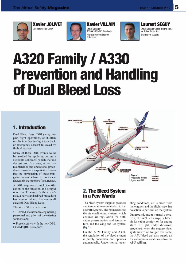
The bleed system supplies pressure
and temperature regulated air to the
aircraft systems. The main users are
the air conditioning system, which
ensures air regulation for both
cabin pressurization and tempera-
ture, and the wing anti-ice system
(fig. 1).
On the A320 Family and A330,
the regulation of the bleed system
is purely pneumatic and operates
automatically. Under normal oper-
ating conditions, air is taken from
the engines and the flight crew has
no action to perform on the system.
On ground, under normal opera-
tion, the APU can su pply bleed
air for cabin comfort or for engine
start. In flight, under abnormal
procedure when the engine bleed
systems are no longer available,
the APU bleed can also supply air
for cabin pressurization (below the
APU ceiling).
Figure 1Pneumatic systemlayout on A330
5Issue 13 | JANUARY 2012The Airbus Safety Magazine
8/12/2019 Airbus Safety First Mag - Jan 2012
http://slidepdf.com/reader/full/airbus-safety-first-mag-jan-2012 6/34
3. Failure Scenariosand Mitigations
A Dual Bleed Loss situation
corresponds to the loss of both
engine bleed air systems. The
non availability of the f irst bleed
system may be triggered by vari-
ous causes, including dispatch
under MMEL, and is monitored
and investigated as part of the
bleed system reliability. A single
remaining engine bleed system is
capable of supplying all the bleed
functions. Under these circum-
stances, a fault on this secondsystem triggers the DBL situation.
The analysis o f DBL events is
focused on the loss of the second
engine bleed system.
3.1 A320 Family
Historically, as indicated in the
Safety First article “A320: Avoiding
Dual Bleed Loss” published in
issue n°7 (February 2009), the
overwhelming majority of second
bleed losses on the A320 Familywere caused by an overtemperature
condition.
3.1.1 Maintenance and Design
Enhancements
In 2008, Airbus introduced new
maintenance procedures and de-
signed a “Dual Bleed Loss package”
(ref. A). This package includes a
new Temperature Control Thermostat
(TCT), a new Fan Air Valve (FAV)
and a new Temperature LimitationThermostat (TLT).
Today, this DBL package equips
more than 70% of the A320
Family fleet (either from pro-
duction or by retrofit) and no
reported Dual Bleed Loss has
been due to the failure of these
new components (fig. 3). A spe-
cific retrofit policy has been
offered to support a prompt in-
service implementation. The few
DBL events reported on this up-
graded fleet were due to instal-
lation issues, such as senseline
leakage between TCT and FAV or
TCT filter clogging (ref. B).
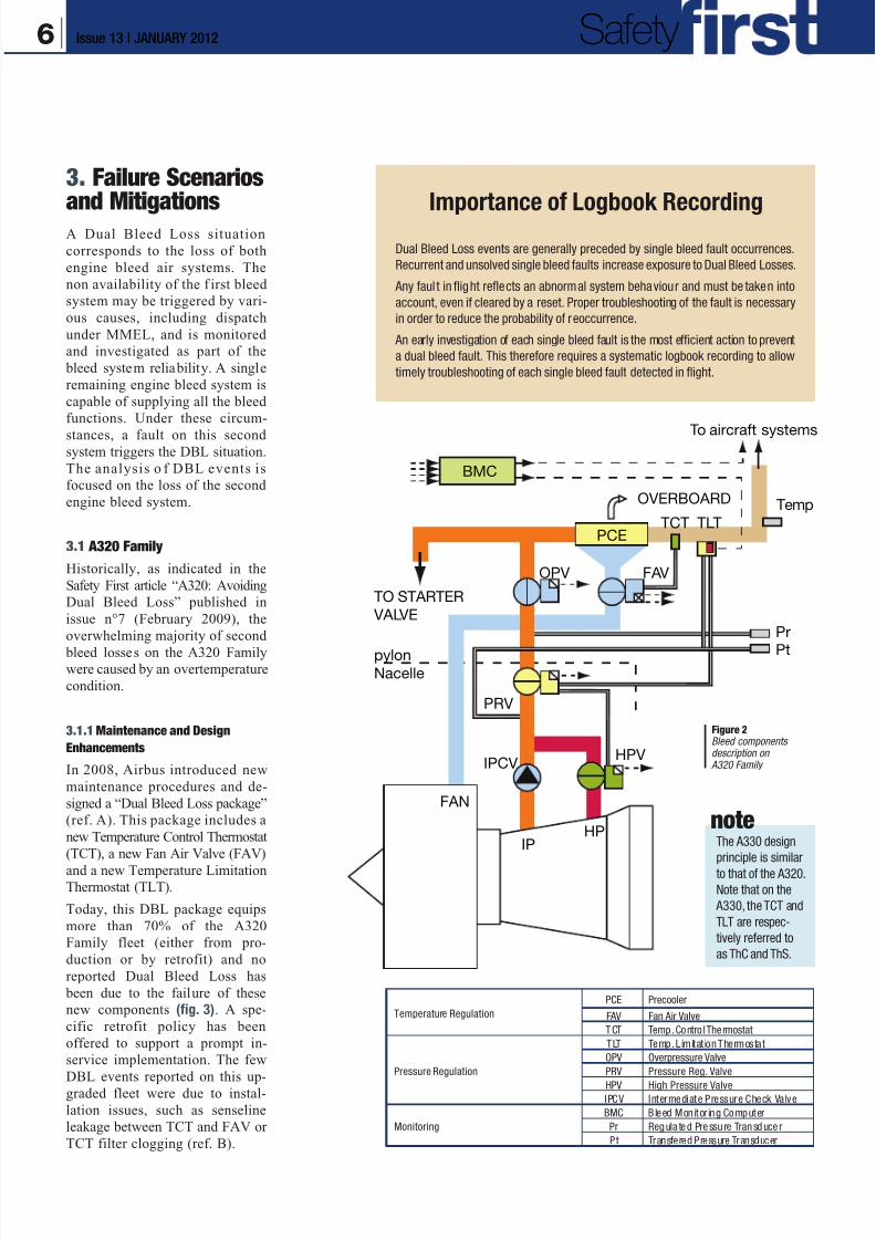
Importance of Logbook Recording
Dual Bleed Loss events are generally preceded by single bleed fault occurrences.
Recurrent and unsolved single bleed faults increase exposure to Dual Bleed Losses.
Any faul t in flight reflects an abnormal system behaviour and must be taken into
account, even if cleared by a reset. Proper troubleshooting of the fault is necessary
in order to reduce the probability of reoccurrence.
An early investigation of each single bleed fault is the most efficient action to prevent
a dual bleed fault. This therefore requires a systematic logbook recording to allow
timely troubleshooting of each single bleed fault detected in flight.
To aircraft systems
BMC
PCE
OVERBOARD
TCT
FAVOPV
TO STARTER
VALVE
pylonNacelle
PRV
IPCV
FAN
IPHP
HPV
TLT
Temp
Pr
Pt
noteThe A330 design
principle is similar
to that of the A320.
Note that on the
A330, the TCT and
TLT are respec-
tively referred to
as ThC and ThS.
Figure 2Bleed componentsdescription on
A320 Family
Temperature Regulation
PCE Precooler
FAV Fan Air Valve
TCT Temp. Contro l Thermostat
Pressure Regulation
TLT Temp. Limitat ion Thermostat
OPV Overpressure Valve
PRV Pressure Reg. Valve
HPV High Pressure ValveIPCV Intermediate Pressure Check Valve
Monitoring
BMC B leed Monitor ing Computer
Pr Regula ted Pressu re Transduce r
Pt Transfered Pressure Transducer
6 Issue 13 | JANUARY 2012 Safety
8/12/2019 Airbus Safety First Mag - Jan 2012
http://slidepdf.com/reader/full/airbus-safety-first-mag-jan-2012 7/34
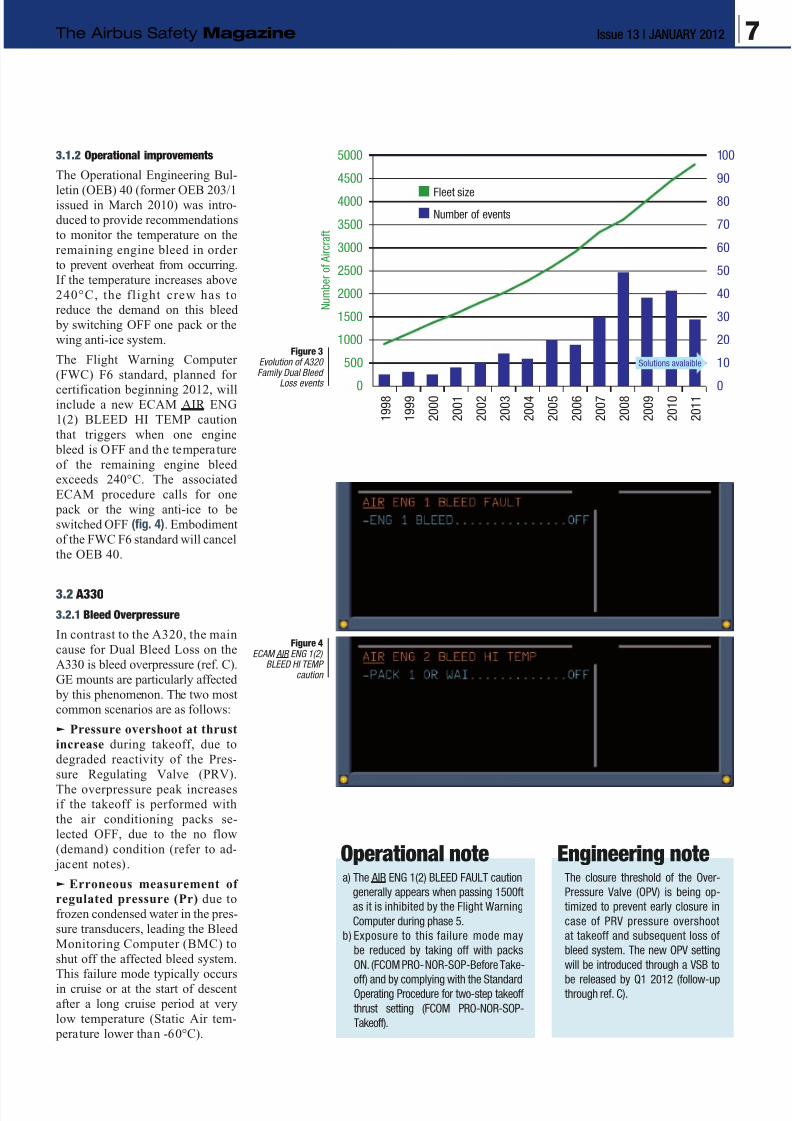
3.1.2 Operational improvements
The Operational Engineering Bul-
letin (OEB) 40 (former OEB 203/1issued in March 2010) was intro-
duced to provide recommendations
to monitor the temperature on the
remaining engine bleed in order
to prevent overheat from occurring.
If the temperature increases above
240°C, the flight crew has to
reduce the demand on this bleed
by switching OFF one pack or the
wing anti-ice system.
The Flight Warning Computer
(FWC) F6 standard, planned for
certification beginning 2012, willinclude a new ECAM AIR ENG
1(2) BLEED HI TEMP caution
that triggers when one engine
bleed is OFF and the temperature
of the remaining engine bleed
exceeds 240°C. The associated
ECAM procedure calls for one
pack or the wing anti-ice to be
switched OFF (fig. 4). Embodiment
of the FWC F6 standard will cancel
the OEB 40.
3.2 A330
3.2.1 Bleed Overpressure
In contrast to the A320, the main
cause for Dual Bleed Loss on the
A330 is bleed overpressure (ref. C).
GE mounts are particularly affected
by this phenomenon. The two most
common scenarios are as follows:
q Pressure overshoot at thrust
increase during takeoff, due to
degraded reactivity of the Pres-
sure Regulating Valve (PRV).
The overpressure peak increasesif the takeoff is performed with
the air conditioning packs se-
lected OFF, due to the no flow
(demand) condition (refer to ad-
jacent notes).
q Erroneous measurement of
regulated pressure (Pr) due to
frozen condensed water in the pres-
sure transducers, leading the Bleed
Monitoring Computer (BMC) to
shut off the affected bleed system.
This failure mode typically occurs
in cruise or at the start of descent
after a long cruise period at very
low temperature (Static Air tem-
perature lower than -60°C).
Figure 3Evolution of A320Family Dual Bleed
Loss events
Operational notea) The AIR ENG 1(2) BLEED FAULT caution
generally appears when passing 1500ft
as it is inhibited by the Flight Warning
Computer during phase 5.
b) Exposure to this failure mode may
be reduced by taking off with packs
ON. (FCOM PRO-NOR-SOP-Before Take-
off) and by complying with the StandardOperating Procedure for two-step takeoff
thrust setting (FCOM PRO-NOR-SOP-
Takeoff).
Engineering noteThe closure threshold of the Over-
Pressure Valve (OPV) is being op-
timized to prevent early closure in
case of PRV pressure overshoot
at takeoff and subsequent loss of
bleed system. The new OPV setting
will be introduced through a VSB to
be released by Q1 2012 (follow-upthrough ref. C).
1 9 9 8
1 9 9 9
2 0 0 0
2 0 0 1
2 0 0 2
2 0 0 3
2 0 0 4
2 0 0 5
2 0 0 6
2 0 0 7
2 0 0 8
2 0 0 9
2 0 1 0
2 0 1 1
N u m b e r o f A i r c r a f t
0
1000
2000
3000
4000
5000
500
1500
2500
3500
4500
0
20
40
60
80
100
10
30
50
70
90
Fleet size
Number of events
Solutions avalaible
Figure 4ECAM AIR ENG 1(2)
BLEED HI TEMPcaution
7Issue 13 | JANUARY 2012The Airbus Safety Magazine
8/12/2019 Airbus Safety First Mag - Jan 2012
http://slidepdf.com/reader/full/airbus-safety-first-mag-jan-2012 8/34
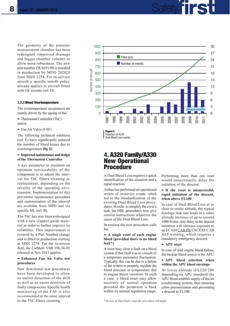
The geometry of the pressure
measurement chamber has been
redesigned (improved drainage
and bigger chamber volume) to
allow more robustness. The new
part number ZRA691-00 is installed
in production by MOD 202028
from MSN 1254. For in-service
aircraft a specific retrofit policy
already applies to aircraft fitted
with GE mounts (ref. D).
3.2.2 Bleed Overtemperature
The overtemperature occurrences are
mainly driven by the ageing of the:q Thermostat Controller (ThC)
and/or
q Fan Air Valve (FAV)
The following technical solutions
(ref. E) have significantly reduced
the number of bleed losses due to
overtemperature (fig. 5):
q Improved maintenance and design
of the Thermostat Controller
A key parameter to maintain an
optimum serviceability of thecomponent is to adjust the inter-
val for ThC filters cleaning or
replacement, depending on the
severity of the operating envi-
ronment. Implementation of this
preventive maintenance procedure
and customization of the interval
are available from MPD and via
specific SIL (ref. B).
The ThC has also been redesigned
with a new clapper/guide mate-
rial in order to further improve its
reliability. This improvement is
covered by a Part Number change
and is fitted in production starting
at MSN 1274. For the in-service
fleet, the Liebherr VSB 398-36-05
released in Nov 2011 applies.
q Enhanced Fan Air Valve test
procedures
New functional test procedures
have been developed to allow
an earlier detection o f the drift
as well as an easier detection o f
faulty components. Specific health
monitori ng of the FAV is a lso
recommended at the same interval
as the ThC filters cleaning.
Performing more than one resetwould unnecessarily delay the
initiation of the descent.
q If the reset is unsuccessful,
rapid initiation of the descent,
when above FL100
In case of Dual Bleed Loss at or
close to cruise altitude, the typicalfuselage leak rate leads to a cabin
altitude increase of up to around1000 ft/min. Any delay in the descent
initiation will increase exposure toan ECAM CAB PR EXCESS CAB
ALT warning, which requires amandatory emergency descent.
q APU start
In case of dual engine bleed failure,the backup bleed source is the APU.
q APU bleed selection when
within the APU bleed envelope
At lower altitude (FL220/200depending on APU standard) the
APU bleed enables supply of the airconditioning system, thus ensuring
cabin pressurization and preventinga descent to FL100.
1 9 9 8
1 9 9 7
1 9 9 9
2 0 0 0
2 0 0 1
2 0 0 2
2 0 0 3
2 0 0 4
2 0 0 5
2 0 0 6
2 0 0 7
2 0 0 8
2 0 0 9
2 0 1 0
2 0 1 10
200
400
600
800
1000
100
300
500
700
900
0
6
3
12
18
24
30
9
15
21
27
Fleet size
Number of events
Solutions avalaible
N u m b e r o f A i r c r a f t
4. A320 Family/A330New OperationalProcedure
A Dual Bleed Loss requires a quickidentification of the situation and arapid reaction.
Airbus has performed an operationalreview of in-service events, whichled to the standardization of theexisting Dual Bleed Loss proce-dures. In order to simplify the crew’stask, the DBL procedures now givesimilar instructions whatever thecause of the Dual Bleed Loss.
In essence the new procedure calls
for:
q A single reset of each engine
bleed (provided there is no bleedleak*)
A reset may clear a fault on a bleedsystem if that fault was as a result ofa temporary parameter fluctuation.Typically, this can be due to a failureof the system to properly regulate the
bleed pressure or temperature dueto engine thrust variation. In sucha case, a bleed reset may allowrecovery of normal operation
provided the parameter is backwithin its normal regulation range.
* In case of bleed leak, a specific procedure will apply.
Figure 5Evolution of A330Dual Bleed Loss events.
8 Issue 13 | JANUARY 2012 Safety
8/12/2019 Airbus Safety First Mag - Jan 2012
http://slidepdf.com/reader/full/airbus-safety-first-mag-jan-2012 9/34
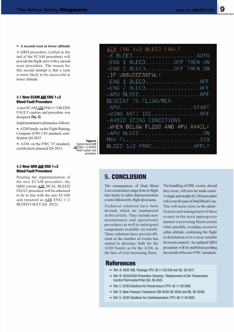
q A second reset at lower altitude
A QRH procedure (called at the
end of the ECAM procedure) will provide the flight crew with a second
reset procedure. The reason for
this second attempt is that a reset
is more likely to be successful at
lower altitude.
4.1 New ECAM AIR ENG 1+2
Bleed Fault Procedure
A new ECAM AIR ENG 1+2 BLEED
FAULT caution and procedure was
designed (fig. 6).
Implementation is planned as follows:
q A320 Family: on the Flight Warning
Computer (FWC) F8 standard, certi-
fication Q4 2015
q A330: on the FWC T5 standard,
certification planned Q4 2012.
4.2 New QRH AIR ENG 1+2
Bleed Fault Procedure
Pending the implementation of
the new ECAM procedure, the
QRH current AIR DUAL BLEED
FAULT procedure will be enhanced
to be in line with the new ECAM
and renamed as AIR ENG 1+2
BLEED FAULT (Q1 2012).
5. CONCLUSION
The consequences of Dual Bleed
Loss occurrences range from in-flight
turn backs to cabin depressurization
events followed by flight diversions.
Technical solutions have been
devised, which are summarized
in this ar ticle. They include new
maintenance and operational
procedures as well as redesigned
components available via retrofit.
These solutions have proved effi-
cient as the number of events has
started to decrease, both for the
A320 Family as for the A330, in
the face of ever increasing fleets.
The handling of DBL events, should
they occur, will now be made easier.
A single and simple ECAM procedure
will cover all cases of Dual Bleed Loss.
This will assist crews in the identi-
fication and management of these
events in the most appropriate
manner (recovering bleed system
when possible, avoiding excessive
cabin altitude, continuing the flightto destination or to a most suitable
diversion airport). An updated QRH
procedure will be published pending
the retrofit of the new FWC standards.
Referencesq Ref. A: A320 DBL Package (TFU 36.11.00.059 and SIL 36-057)
q Ref. B: A320/A330 Preventive Cleaning / Replacement of the Temperature
Control Thermostat Filter (SIL 36-055)
q Ref. C: A330 Solutions for Overpressure (TFU 36.11.00.069)
q Ref. D: New Pressure Transducer (SB A330-36-3039 and RIL 36-3039)
q Ref. E: A330 Solutions for Overtemperature (TFU 36.11.00.065)
Figure 6Typical new ECAM
AIR ENG 1+2 BLEEDFAULT caution and
procedure
9Issue 13 | JANUARY 2012The Airbus Safety Magazine

8/12/2019 Airbus Safety First Mag - Jan 2012
http://slidepdf.com/reader/full/airbus-safety-first-mag-jan-2012 10/34
Thomas LEPAGNOTSenior Engineer, A320/A330/A340 StandardsFlight Operations Support and Safety Enhancement
The Fuel Penalty FactorFailures Affecting the Fuel Consumption
A320 Family and A330/A340
2. Failures Affecting the FuelConsumption
All failures that affect the nominal
aerodynamic characteristics of the
aircraft will also increase its fuel
consumption. The additional drag
penalty drag has to be compensated
by an increase in thrust (to maintainthe same flight conditions) or by a
descent to a lower flight level (if
there is no thrust margin).
The two main sources of additional
drag are:
q A failure affecting the flight
control surfaces, which may leadto three specific conf igurations,generating each a different amountof drag:
• The surface is blocked in itsfull deflection position (runaway),or
• The surface is free and oatsin the wind (zero hinge moment
position), or
• The surface (only applicable tospoilers) slowly extends over time,after the loss of its hydraulic actua-tion (spoiler drift, see explanationsin box below).
q A failure affecting the landing
gears or landing gear doors re-
traction function, which will lead
to the gears, or doors, remaining
extended.
1. Introduction
Monitoring the fuel consumption
all along a mission is one of the
most important tasks of the flight
crew. This general statement was
already highlighted in the Safety
First article “Low Fuel Situation
Awareness” published in issue n°6
(July 2008). This article stressed
the following points:q The importance of the different
fuel checks in cruise, to detect an
abnormal fuel situation
q The functionality limitations of the
Flight Management System (FMS)
in terms of fuel predictions, under
non-nominal aircraft conditions.
In this new article, we will focus
on the second theme: The FMS
Estimated Fuel On Board (EFOB)
predictions do not cur rently take
into account the in-flight failures
that have an impact on th e fuel
consumption. The only exception
is the one engine out failure, once
confirmed in the FMS. For all other
cases, the FMS predictions should be corrected to take into account
the consequences of these failures
in terms of excessive fuel consump-
tion.The purpose of this article is to present
new developments in terms of:
q Documentation and procedure
that have been introduced in Novem-
ber of 2011
q Coming standards of Flight
Warning Computers that will soon become available.
These enhancements were designed
to improve the crews’ awareness of
the fuel consumption increase gen-
erated by certain failures.
10 Issue 13 | JANUARY 2012 Safety

8/12/2019 Airbus Safety First Mag - Jan 2012
http://slidepdf.com/reader/full/airbus-safety-first-mag-jan-2012 11/34
We can segregate these failures
into four systems : ELEC, F/CTL,
HYD, L/G.
In case of hydraulic system failure, some
spoilers will no longer operate. An anti-
extension device will avoid the deflection
of the spoiler. However, depending on the
condition of the spoiler servo control, this
anti-extension device could be sensitive
to temperature variations or prone to
actuator leak. In that case, the spoiler
may not be maintained retracted and
may extend over time up to its zero hinge
moment position.
Let us consider the cockpit effects of
such a failure mode on an A320:
q First, the Hydraulic failure (HYD G SYS
LO PR for instance), with all affected spoilers
indicated fault retracted in amber on the
ECAM Flight Control page (fig. 1A).
q If one of the affected spoilers (n°5 left,
for instance) drifts, no indication will appear
on the ECAM as long as the extension
value remains below 2.5°.
q Once it crosses that threshold, a F/CTL
SPLR FAULT amber caution is triggeredand the affected spoiler is indicated fault
deflected in amber on the ECAM F/CTL
page (fig. 1B).
q From then on, it is considered that the
affected spoiler generates a non negli-
gible increase of the fuel consumption,
which will evolve over time, as the spoiler
extends further.
noteIndeed, as the flight control surfaces
are all electrically controlled, and
hydraulically activated, some ELEC
and/or HYD failures will lead to the
loss of flight control surfaces (ailerons
and/or spoilers).
SPOILER DRIFT
Figure 1A A320 ECAM F/CTL page: affected spoilers indicated fault retracted
Figure 1B A320 ECAM F/CTL page: spoiler n°5 indicated fault deflected
Figure 1CIllustration of
spoiler drifton an A330
11Issue 13 | JANUARY 2012The Airbus Safety Magazine
8/12/2019 Airbus Safety First Mag - Jan 2012
http://slidepdf.com/reader/full/airbus-safety-first-mag-jan-2012 12/34
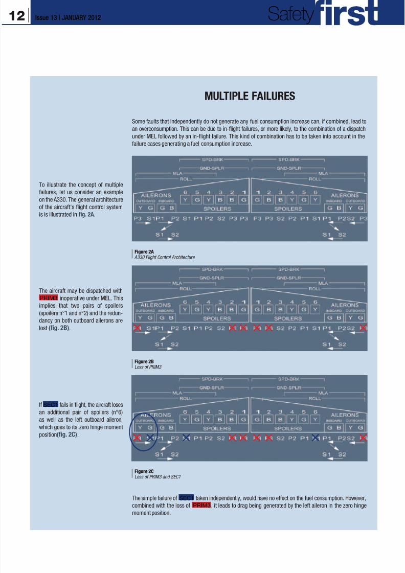
If SEC1 fails in flight, the aircraft loses
an additional pair of spoilers (n°6)
as well as the left outboard aileron,
which goes to its zero hinge moment
position(fig. 2C).
The aircraft may be dispatched with
PRIM3
inoperative under MEL. Thisimplies that two pairs of spoilers
(spoilers n°1 and n°2) and the redun-
dancy on both outboard ailerons are
lost (fig. 2B).
To illustrate the concept of multiple
failures, let us consider an example
on the A330. The general architectureof the aircraft’s flight control system
is is illustrated in fig. 2A.
Some faults that independently do not generate any fuel consumption increase can, if combined, lead to
an overconsumption. This can be due to in-flight failures, or more likely, to the combination of a dispatch
under MEL followed by an in-flight failure. This kind of combination has to be taken into account in the
failure cases generating a fuel consumption increase.
The simple failure of SEC1 taken independently, would have no effect on the fuel consumption. However,
combined with the loss of PRIM3 , it leads to drag being generated by the left aileron in the zero hinge
moment position.
Figure 2A A330 Flight Control Architecture
Figure 2BLoss of PRIM3
Figure 2CLoss of PRIM3 and SEC1
MULTIPLE FAILURES
12 Issue 13 | JANUARY 2012 Safety
8/12/2019 Airbus Safety First Mag - Jan 2012
http://slidepdf.com/reader/full/airbus-safety-first-mag-jan-2012 13/34
The flight control and landing gear/
landing gear doors malfunctions
may be caused by either simple or
multiple failures (see explanationsin box above).
3. InformationProvided to theFlight Crewup to Nov 2011
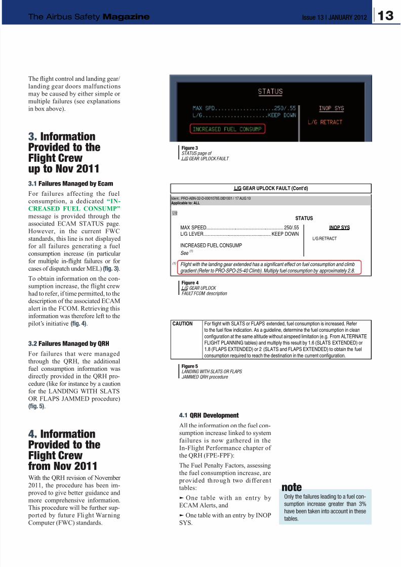
3.1 Failures Managed by Ecam
For failures affecting the fuel
consumption, a dedicated “IN-
CREASED FUEL CONSUMP”
message is provided through the
associated ECAM STATUS page.
However, in the current FWC
standards, this line is not displayedfor all failures generating a fuel
consumption increase (in particular
for multiple in-flight failures or for
cases of dispatch under MEL) (fig. 3).
To obtain information on the con-
sumption increase, the flight crew
had to refer, if time permitted, to thedescription of the associated ECAM
alert in the FCOM. Retrieving this
information was therefore left to the
pilot’s initiative (fig. 4).
3.2 Failures Managed by QRH
For failures that were managed
through the QRH, the additionalfuel consumption information was
directly provided in the QRH pro-
cedure (like for instance by a caution
for the LANDING WITH SLATS
OR FLAPS JAMMED procedure)(fig. 5).
4. InformationProvided to theFlight Crewfrom Nov 2011With the QRH revision of November
2011, the procedure has been im-
proved to give better guidance and
more comprehensive information.This procedure will be further sup-
ported by future Flight Warning
Computer (FWC) standards.
4.1 QRH Development
All the information on the fuel con-sumption increase linked to system
failures is now gathered in the
In-Flight Performance chapter of
the QRH (FPE-FPF):
The Fuel Penalty Factors, assessing
the fuel consumption increase, are
provided through two di fferen ttables:
q One table with an entry byECAM Alerts, and
q One table with an entry by INOP
SYS.
L/G GEAR UPLOCK FAULT (Cont'd)
Ident.: PRO-ABN-32-D-00010765.0001001 / 17 AUG 10Applicable to: ALL
L12
STATUS
MAX SPEED................................................................ 250/.55
L/G LEVER........................................................ KEEP DOWN
INCREASED FUEL CONSUMP
See(1)
INOP SYS
L/G RETRACT
(1) Flight with the landing gear extended has a significant effect on fuel consumption and climb gradient (Refer to PRO-SPO-25-40 Climb). Multiply fuel consumption by approximately 2.8.
CAUTION For flight with SLATS or FLAPS extended, fuel consumption is increased. Referto the fuel flow indication. As a guideline, determine the fuel consumption in clean
configuration at the same altitude without airspeed limitation (e.g. From ALTERNATEFLIGHT PLANNING tables) and multiply this result by 1.6 (SLATS EXTENDED) or
1.8 (FLAPS EXTENDED) or 2 (SLATS and FLAPS EXTENDED) to obtain the fuelconsumption required to reach the destination in the current configuration.
Figure 3STATUS page ofL/G GEAR UPLOCK FAULT
Figure 4L/G GEAR UPLOCKFAULT FCOM description
Figure 5LANDING WITH SLATS OR FLAPSJAMMED QRH procedure
noteOnly the failures leading to a fuel con-sumption increase greater than 3%
have been taken into account in these
tables.
13Issue 13 | JANUARY 2012The Airbus Safety Magazine
8/12/2019 Airbus Safety First Mag - Jan 2012
http://slidepdf.com/reader/full/airbus-safety-first-mag-jan-2012 14/34
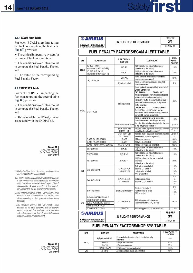
4.1.1 ECAM Alert Table
For each ECAM alert impacting
the fuel consumption, the first table(fig. 6A) provides:
q The critical inoperative system(s)
in terms of fuel consumption
q The conditions taken into account
to compute the Fuel Penalty Factor,
and
q The value of the correspondingFuel Penalty Factor.
4.1.2 INOP SYS Table
For each INOP SYS impacting the
fuel consumption, the second table(fig. 6B) provides:
q The conditions taken into account
to compute the Fuel Penalty Factor,
and
q The value of the Fuel Penalty Factor
associated with the INOP SYS.
Figure 6A A320 Fuel Penalty
Factor table / ECAMalert entry
Figure 6B A320 Fuel PenaltyFactor table / INOP
SYS entry
( 1) During the flight, the spoiler(s) may gradually extend
and increase the fuel consumption.
(2) A spoiler can be suspected fully extended (runaway)
if high roll rate has been experienced immediately
after the failure, associated with a possible AP
disconnection. A visual inspection, if time permits,
can also confirm the full extension of the spoiler.
(3) The maximum value of the Fuel Penalty Factor
provided in the table considers that the two pairs
of corresponding spoilers gradually extend during
the flight.
(4) The minimum value of the Fuel Penalty Factor
provided in the table considers that all spoilers
remain retracted. The maximum value has been
calculated considering that all impacted spoilers
gradually extend during the flight.
14 Issue 13 | JANUARY 2012 Safety
8/12/2019 Airbus Safety First Mag - Jan 2012
http://slidepdf.com/reader/full/airbus-safety-first-mag-jan-2012 15/34
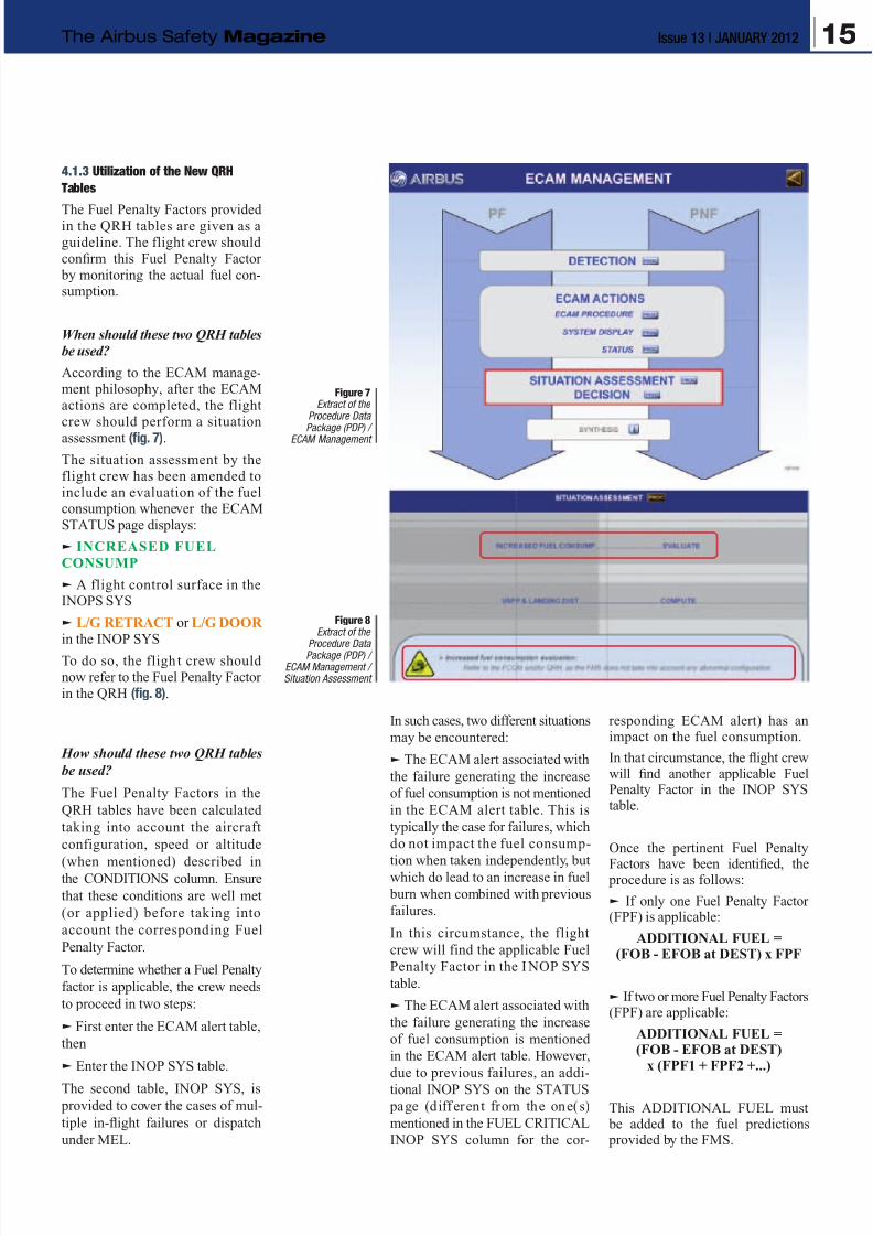
4.1.3 Utilization of the New QRH
Tables
The Fuel Penalty Factors providedin the QRH tables are given as a
guideline. The flight crew should
confirm this Fuel Penalty Factor
by monitoring the actual fuel con-sumption.
When should these two QRH tables
be used?
According to the ECAM manage-ment philosophy, after the ECAM
actions are completed, the flight
crew should perform a situation
assessment (fig. 7).
The situation assessment by the
flight crew has been amended to
include an evaluation of the fuelconsumption whenever the ECAM
STATUS page displays:
q INCREASED FUEL
CONSUMP
q A flight control surface in theINOPS SYS
q L/G RETRACT or L/G DOOR
in the INOP SYS
To do so, the fligh t crew should
now refer to the Fuel Penalty Factor
in the QRH (fig. 8).
How should these two QRH tables
be used?
The Fuel Penalty Factors in the
QRH tables have been calculated
taking into account the aircraft
configuration, speed or altitude
(when mentioned) described inthe CONDITIONS column. Ensure
that these conditions are well met
(or applied) before taking into
account the corresponding Fuel
Penalty Factor.
To determine whether a Fuel Penalty
factor is applicable, the crew needs
to proceed in two steps:
q First enter the ECAM alert table,
then
q Enter the INOP SYS table.
The second table, INOP SYS, is
provided to cover the cases of mul-
tiple in-flight failures or dispatch
under MEL.
In such cases, two different situations
may be encountered:
q The ECAM alert associated with
the failure generating the increase
of fuel consumption is not mentioned
in the ECAM alert table. This is
typically the case for failures, which
do not impact the fuel consump-
tion when taken independently, butwhich do lead to an increase in fuel
burn when combined with previous
failures.
In this circumstance, the flight
crew will find the applicable Fuel
Penalty Factor in the INOP SYS
table.
q The ECAM alert associated with
the failure generating the increase
of fuel consumption is mentioned
in the ECAM alert table. However,
due to previous failures, an addi-
tional INOP SYS on the STATUS
page (diff erent from the one(s)
mentioned in the FUEL CRITICAL
INOP SYS column for the cor-
responding ECAM alert) has animpact on the fuel consumption.
In that circumstance, the flight crewwill find another applicable FuelPenalty Factor in the INOP SYStable.
Once the pertinent Fuel Penalty
Factors have been identified, the procedure is as follows:
q If only one Fuel Penalty Factor(FPF) is applicable:
ADDITIONAL FUEL =(FOB - EFOB at DEST) x FPF
q If two or more Fuel Penalty Factors(FPF) are applicable:
ADDITIONAL FUEL =(FOB - EFOB at DEST)
x (FPF1 + FPF2 +...)
This ADDITIONAL FUEL must be added to the fuel predictions provided by the FMS.
Figure 7Extract of the
Procedure Data
Package (PDP) /ECAM Management
Figure 8Extract of the
Procedure DataPackage (PDP) /
ECAM Management /Situation Assessment
15Issue 13 | JANUARY 2012The Airbus Safety Magazine
8/12/2019 Airbus Safety First Mag - Jan 2012
http://slidepdf.com/reader/full/airbus-safety-first-mag-jan-2012 16/34
4.2 ECAM Development
With future Flight Warning Com-
puter (FWC) standards, all failure
cases leading to an increase in fuel
consumption of more than 3%,
including multiple in-flight failures
and dispatch under MEL, will triggera “FUEL CONSUMPT INCRSD”
message on the ECAM STATUS
page. This message will be com-
plemented wi th a “FMS PRED
UNRELIABLE” line to highlight
the unreliability of the FMS (fig. 9).
The same wording will also be usedin the associated ECAM procedure.
All these improvements will be
introduced in the following FWC
standards:
q A320 Family: H2F7 stan dard(certification planned for December
2012)
q A330 and A340-500/600 : T5
standard (certification planned for
January 2013)
q A340-200/300: L13 standa rd(certif ication planned for August
2013).
5. CONCLUSIONAfter an in-flight failure, it is es-
sential for the flight crew to have
a clear view of all the operational
consequences generated by this
failure. In particular, when the fuelconsumption is affected, the pilot
should have means to estimate this
impact.
This is the purpose of this new policy
supported by new QRH tables and
future developments implementedin the next FWC standards. The
information is now concentrated in
one part of the Operational Docu-
mentation (simplified access), takes
into account more operational cases
(multiple failure, dispatch under
MEL), and the associated procedure
is more formalized.
This policy ensures a standardized
and common treatment of all the
failures impacting the fuel con-
sumption, by giving the same level
of information to all flight crew.
It improves crew awareness on con-sequences of such failures, and as a
result, represents a new step in the
safety of airline operations.
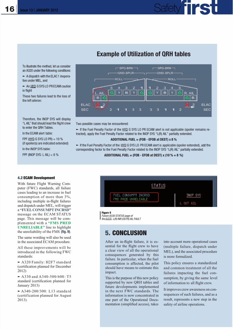
Example of Utilization of QRH tables
To illustrate the method, let us consider
an A320 under the following conditions:
q A dispatch with the ELAC 1 inopera-
tive under MEL, and
q An HYD G SYS LO PR ECAM caution
in flight
These two failures lead to the loss of
the left aileron:
Therefore, the INOP SYS will display
“L AIL” that should lead the flight crew
to enter the QRH Tables.
In the ECAM alert table:
FPF (HYD G SYS LO PR) = 10 %
(if spoiler(s) are indicated extended)
In the INOP SYS table:
FPF (INOP SYS: L AIL) = 8 %
Two possible cases may be encountered:
q If the Fuel Penalty Factor of the HYD G SYS LO PR ECAM alert is not applicable (spoiler remains re-
tracted), apply the Fuel Penalty Factor related to the INOP SYS “L(R) AIL” partially extended.
ADDITIONAL FUEL = (FOB - EFOB at DEST) x 8 %
q If the Fuel Penalty Factor of the HYD G SYS LO PR ECAM alert is applicable (spoiler extended), add the
corresponding factor to the Fuel Penalty Factor related to the INOP SYS “L(R) AIL” partially extended.
ADDITIONAL FUEL = (FOB - EFOB at DEST) x (10 % + 8 %)
Figure 9Future A330 STATUS page ofthe F/CTL L(R) INR (OUTR) AIL FAULT
16 Issue 13 | JANUARY 2012 Safety
8/12/2019 Airbus Safety First Mag - Jan 2012
http://slidepdf.com/reader/full/airbus-safety-first-mag-jan-2012 17/34
Paule BOTARGUESEngineer, Automatic Flight Systems Research,Engineering Department
The Airbus TCASAlert Prevention (TCAP)
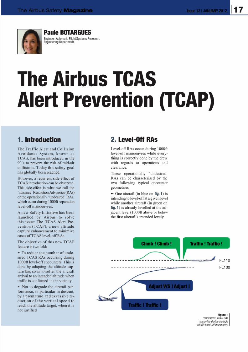
2. Level-Off RAs
Level-off RAs occur during 1000ft
level-off manoeuvres while every-
thing is correctly done by the crew
with regards to operations and
clearance.
These operationally ‘undesired’RAs can be characterised by the
two following typical encounter
geometries:
q One aircraft (in blue on fig. 1) is
intending to level-off at a given level
while another aircraft (in green onfig. 1) is already levelled at the ad-
jacent level (1000ft above or below
the first aircraft’s intended level):
1. Introduction
The Traffic Alert and Coll ision
Avoidance System, known as
TCAS, has been introduced in the90’s to prevent the risk of mid-air
collisions. Today this safety goal
has globally been reached.
However, a recurrent side-effect of
TCAS introduction can be observed.This side-effect is what we call the
‘nuisance’ Resolution Advisories (RAs)or the operationally ‘undesired’ RAs,
which occur during 1000ft separation
level-off manoeuvres.
A new Safety Initiative has been
launched by Airbus to solve
this issue: The TCAS Alert Pre-vention (TCAP), a new altitude
capture enhancement to minimize
cases of TCAS level-off RAs.
The objective of this new TCAP
feature is twofold:q To reduce the number of unde-
sired TCAS RAs occurring during
1000ft level-off encounters. This is
done by adapting the altitude cap-
ture law, so as to soften the aircraft
arrival to an intended altitude when
traffic is confirmed in the vicinity.
q Not to degrade the aircraft per-
formance, in particular in descent,
by a premature and excessive re-
duction of the vertical spee d to
reach the altitude target, when it is
not justified.
FL110
FL100
Traffic ! Traffic !
Climb ! Climb ! Traffic ! Traffic !
Adjust V/S ! Adjust !
Figure 1‘Undesired’ TCAS RAs
occurring during a single1000ft level-off manoeuvre
17Issue 13 | JANUARY 2012The Airbus Safety Magazine
8/12/2019 Airbus Safety First Mag - Jan 2012
http://slidepdf.com/reader/full/airbus-safety-first-mag-jan-2012 18/34
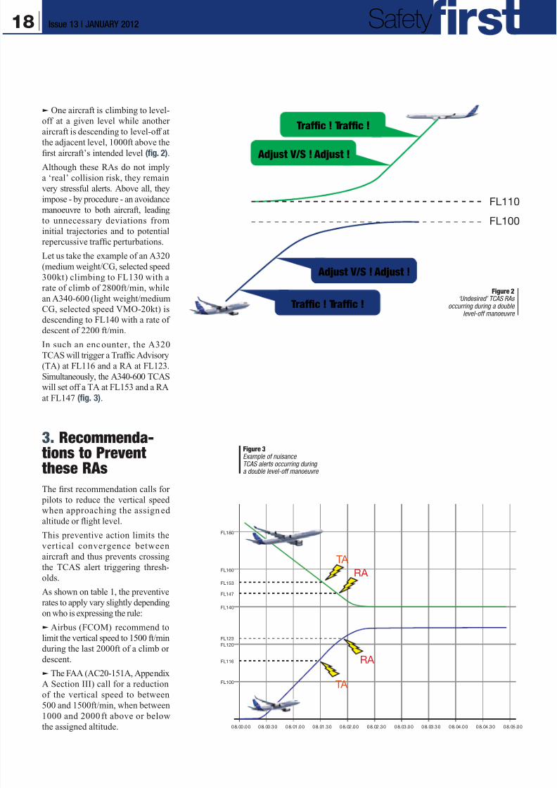
q One aircraft is climbing to level-
off at a given level while another
aircraft is descending to level-off at
the adjacent level, 1000ft above the
first aircraft’s intended level (fig. 2).
Although these RAs do not imply
a ‘real’ collision risk, they remain
very stressful alerts. Above all, they
impose - by procedure - an avoidance
manoeuvre to both aircraft, leading
to unnecessary deviations from
initial trajectories and to potential
repercussive traffic perturbations.
Let us take the example of an A320
(medium weight/CG, selected speed
300kt) climbing to FL130 with arate of climb of 2800ft/min, while
an A340-600 (light weight/medium
CG, selected speed VMO-20kt) is
descending to FL140 with a rate of
descent of 2200 ft/min.
In such an enc ounter, the A320
TCAS will trigger a Traffic Advisory
(TA) at FL116 and a RA at FL123.
Simultaneously, the A340-600 TCAS
will set off a TA at FL153 and a RA
at FL147 (fig. 3).
3. Recommenda-tions to Preventthese RAs
The first recommendation calls for
pilots to reduce the vertical speed
when approaching the assign ed
altitude or flight level.
This preventive action limits the
vertical convergence between
aircraft and thus prevents crossing
the TCAS alert triggering thresh-
olds.
As shown on table 1, the preventive
rates to apply vary slightly depending
on who is expressing the rule:
q Airbus (FCOM) recommend to
limit the vertical speed to 1500 ft/min
during the last 2000ft of a climb or
descent.
q The FAA (AC20-151A, Appendix
A Section III) call for a reduction
of the vertical speed to between
500 and 1500ft/min, when between
1000 and 2000ft above or below
the assigned altitude.
FL110
FL100
FL100
08.00.00 08.00.30 08.01.00 08.01.30 08.02.00 08.02.30 08.03.00 08.03.30 08.04.00 08.04.30 08.05.00
FL120
FL140
FL160
FL153
FL147
FL123
FL116
FL180
TA
TA
RA
RA
Figure 3Example of nuisanceTCAS alerts occurring duringa double level-off manoeuvre
Traffic ! Traffic !
Traffic ! Traffic !
Adjust V/S ! Adjust !
Adjust V/S ! Adjust !Figure 2
‘Undesired’ TCAS RAsoccurring during a double
level-off manoeuvre
18 Issue 13 | JANUARY 2012 Safety
8/12/2019 Airbus Safety First Mag - Jan 2012
http://slidepdf.com/reader/full/airbus-safety-first-mag-jan-2012 19/34
q ICAO (PANS-OPS Doc. 8168)
recommend to adopt a vertical
speed below 1500ft/min throughout
the last 1000ft of climb or descent tothe assigned altitude.
q Table 1 also includes the limits
in vertical speed from three other
sources.
As a matter of fact, these recommen-
dations are rarely applied. Several
airlines do not have them incorporated
in their operational recommendations.
Even when they are, some pilots
confess they are not always applied.
As a result there is still a significant
number of undesired RAs observedduring 1000ft level-off manoeuvres.
The second set of recommendation
has been expressed by the French
accident investigation authority
Bureau d’Enquête et d’Analyses
(BEA) following a mid-air incident,
in March 2003, where a wrong
respon se to an “ADJUST V/S”
RA was observed in a context of
a 1000ft level-off encounter. The
BEA recommended that aircraft
manufacturers study the possibility
of taking into account TCAS alerttriggering thresholds into their alti-
tude capture laws.
This recommendation was followed
by EUROCONTROL within the
ACAS Bulletins and by several air-
lines who requested a modification
of the altitude capture control laws
with an earlier reduction of the ver-
tical rate to prevent such recurrent
undesired RAs.
4. The TCAP Function
In response to these requests for
improvement, Airbus launched the
feasibility study of a new system
called TCAS Alert Prevention or
TCAP.
The objective of this new TCAP
feature is twofold:
q To reduce the number of unde-
sired TCAS RAs occurring during
1000ft level-off encounters. This is
done by adapting the altitude cap-
ture law, so as to soften the aircraft
arrival to an intended altitude when
traffic is confirmed in the vicinity.
q Not to degrade the aircraft per-
formance, in particular in descent, bya premature and excessive reduction
of the vertical speed to reach the al-titude target, when it is not justified.
The TCAP activation logic is based
on the Traffic Advisory (TA) trig-
gered by the TCAS, which clearlyconfirms the presence of traffic in
the aircraft vicinity.
The activation of TCAP is fully
transparent to the pilot who will
note the same mode changes with
TCAP as without TCAP. The TCAP
case only resulting in an earlier re-duction of the Rate Of Descent/
Rate Of Climb (ROD/ROC). Thismeans that upon TCAP activation
at TA:
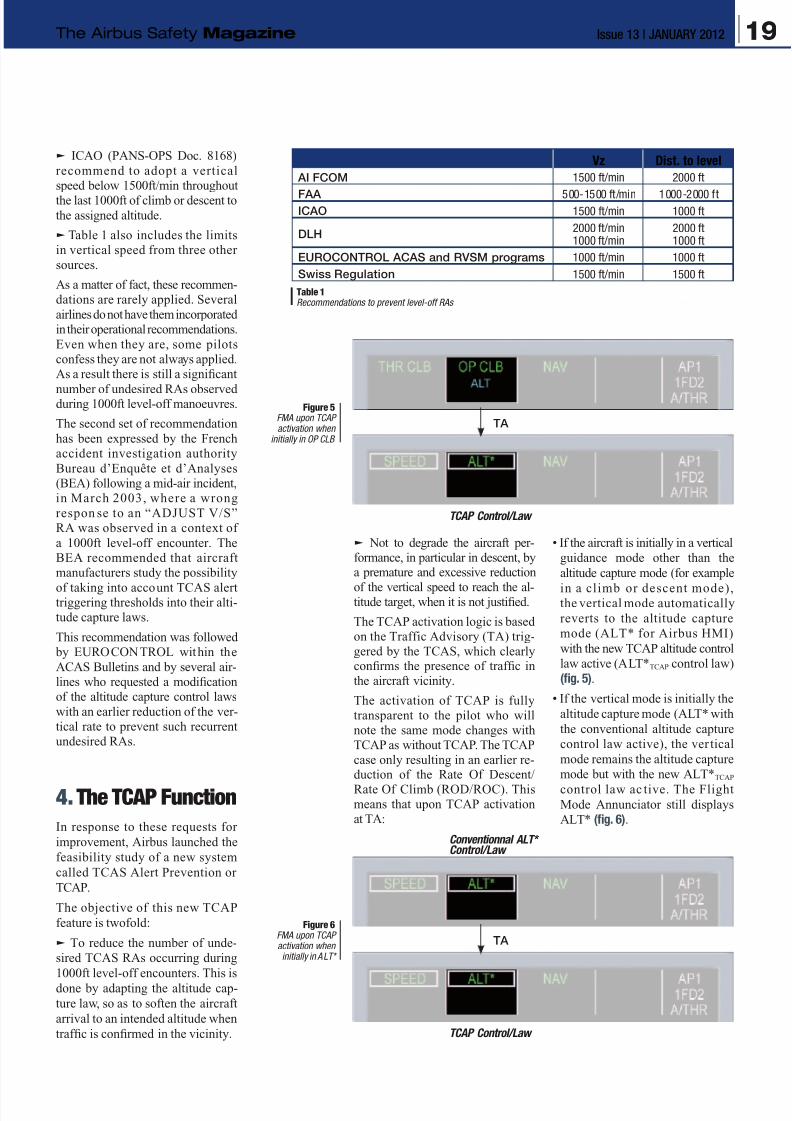
• If the aircraft is initially in a vertical
guidance mode other than the
altitude capture mode (for example
in a climb or descent mode),the vertical mode automatically
reverts to the altitude capture
mode (ALT* for Airbus HMI)
with the new TCAP altitude control
law active (ALT*TCAP control law)
(fig. 5).
• If the vertical mode is initially the
altitude capture mode (ALT* with
the conventional altitude capture
control law active), the ver tical
mode remains the altitude capture
mode but with the new ALT*TCAP
control law ac tive. The FlightMode Annunciator still displays
ALT* (fig. 6).
Table 1Recommendations to prevent level-off RAs
Vz Dist. to level
AI FCOM 1500 ft/min 2000 ft
FAA 500-1500 ft/min 1000-2000 ftICAO 1500 ft/min 1000 ft
DLH2000 ft/min1000 ft/min
2000 ft1000 ft
EUROCONTROL ACAS and RVSM programs 1000 ft/min 1000 ft
Swiss Regulation 1500 ft/min 1500 ft
Figure 6FMA upon TCAPactivation wheninitially in ALT*
Figure 5FMA upon TCAPactivation when
initially in OP CLB
TA
TA
TCAP Control/Law
TCAP Control/Law
Conventionnal ALT*Control/Law
19Issue 13 | JANUARY 2012The Airbus Safety Magazine
8/12/2019 Airbus Safety First Mag - Jan 2012
http://slidepdf.com/reader/full/airbus-safety-first-mag-jan-2012 20/34
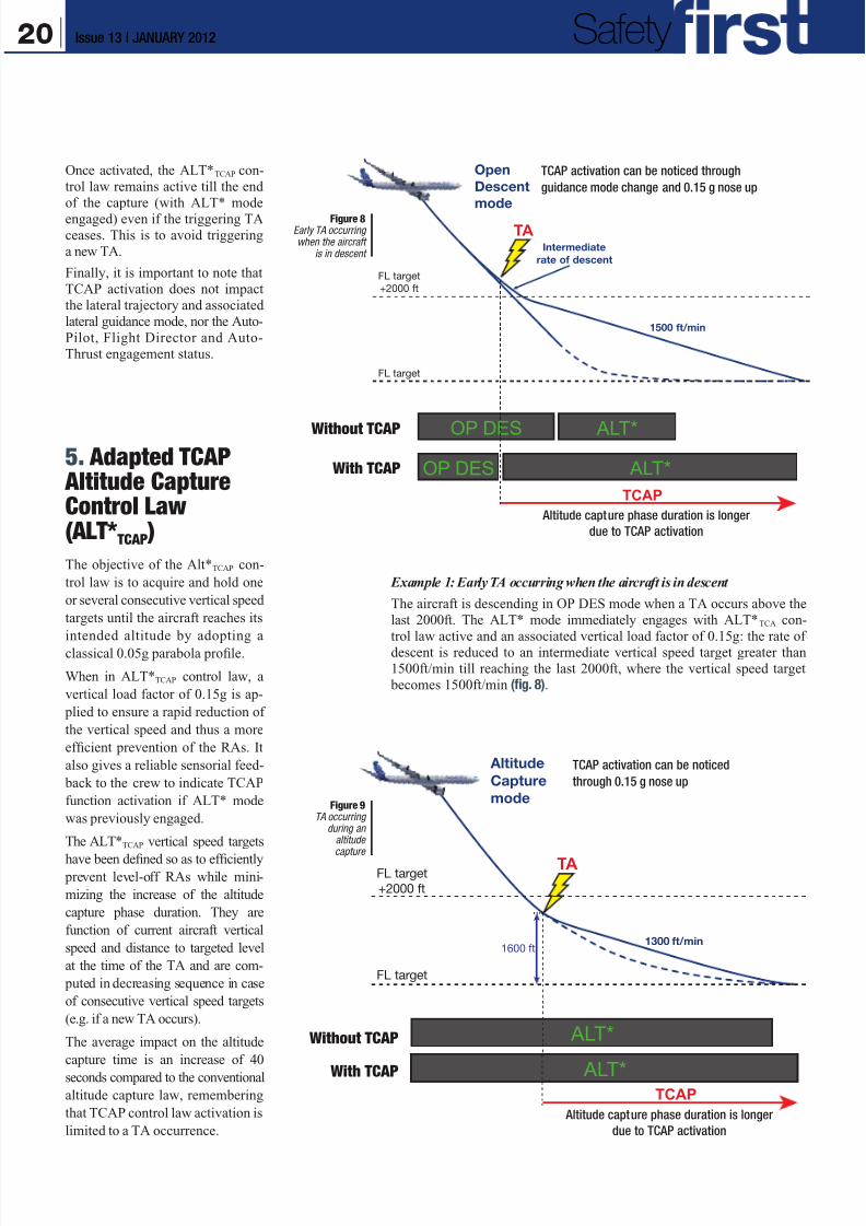
Once activated, the ALT*TCAP con-
trol law remains active till the end
of the capture (with ALT* mode
engaged) even if the triggering TAceases. This is to avoid triggering
a new TA.
Finally, it is important to note that
TCAP activation does not impact
the lateral trajectory and associated
lateral guidance mode, nor the Auto-
Pilot, Flight Director and Auto-
Thrust engagement status.
5. Adapted TCAP Altitude CaptureControl Law(ALT* TCAP )
The objective of the Alt*TCAP con-
trol law is to acquire and hold one
or several consecutive vertical speed
targets until the aircraft reaches its
intended altitude by adopting a
classical 0.05g parabola profile.
When in ALT*TCAP control law, a
vertical load factor of 0.15g is ap-
plied to ensure a rapid reduction of
the vertical speed and thus a more
efficient prevention of the RAs. It
also gives a reliable sensorial feed-
back to the crew to indicate TCAP
function activation if ALT* mode
was previously engaged.
The ALT*TCAP vertical speed targets
have been defined so as to efficiently prevent level-off RAs while mini-
mizing the increase of the altitude
capture phase duration. They are
function of current aircraft vertical
speed and distance to targeted level
at the time of the TA and are com-
puted in decreasing sequence in case
of consecutive vertical speed targets
(e.g. if a new TA occurs).
The average impact on the altitude
capture time is an increase of 40
seconds compared to the conventionalaltitude capture law, remembering
that TCAP control law activation is
limited to a TA occurrence.
Example 1: Early TA occurring when the aircraft is in descent
The aircraft is descending in OP DES mode when a TA occurs above the
last 2000ft. The ALT* mode immediately engages with ALT*TCA con-
trol law active and an associated vertical load factor of 0.15g: the rate of
descent is reduced to an intermediate vertical speed target greater than
1500ft/min till reaching the last 2000ft, where the vertical speed target
becomes 1500ft/min (fig. 8).
Altitude capture phase duration is longer
due to TCAP activation
Figure 8Early TA occurringwhen the aircraft
is in descent
TA
ALT*
ALT*
FL target
+2000 ft
Altitude
Capture
mode
1300 ft/min
FL target
1600 ft
TCAP
TCAP activation can be noticed
through 0.15 g nose up
Altitude capture phase duration is longer
due to TCAP activation
Figure 9TA occurring
during analtitudecapture
TA
OP DES
OP DES
ALT*
ALT*
FL target
+2000 ft
Open
Descent
mode
1500 ft/min
Intermediate
rate of descent
FL target
TCAP
Without TCAP
With TCAP
Without TCAP
With TCAP
TCAP activation can be noticed through
guidance mode change and 0.15 g nose up
20 Issue 13 | JANUARY 2012 Safety

8/12/2019 Airbus Safety First Mag - Jan 2012
http://slidepdf.com/reader/full/airbus-safety-first-mag-jan-2012 21/34
Example 2: TA occurring during
an altitude capture (in ALT*)
The aircraft is performing an alti-
tude capture on the conventional0.05g parabola capture profile
(ALT* mode) when a TA occurs.
The ALT*TCAP law automatically
activates to quickly reduce the rate
of descent, shortcutting the parabola
with a vertical load factor of 0.15g
(ALT* mode remains engaged).
The rate of descent is reduced to a
vertical speed target between 1200ft/
min and 1500ft/min depending on
the aircraft’s distance to the target
flight level at the time of the TA till
the end of the capture (fig. 9).
6. ExpectedBenefits
An operational and safety perform-
ance assessment was performed in
the frame of the Single European
Sky ATM Research (SESAR) project
to assess the impact of the new Airbus
TCAP solution, based on a large
encounter model representative ofoperations in Europe.
The assessment showed that more
than 95% of the 1000ft level-off
RAs were avoided through the use
of TCAP. Since 1000ft level-offRAs represent more than 55% of
all RAs, the project concluded that
TCAP may halve the overall number
of RAs for an equipped aircraft.
Another observed relevant result
was that only one aircraft of the en-counter needs to be equipped withTCAP to allow RAs prevention on
both aircraft (fig. 10).
7. ConclusionWith significant operational benefits
such as more than 95% level-off
RAs avoided, leading to an overall
number of RAs cut by two without
debasing safety, TCAP establishes
as a promising standard.
These benefits will be associated to
the following outcomes:
q For the crew: less stress due to a
reduced number of RA situations,
q For ATC: less unnecessary traffic
perturbations due to ‘undue’ avoid-ance manoeuvres.
The TCAP will also contribute to
the crew workload alleviation: even
though pilots still have to maintain
awareness and vigilance over near
by traffic, they will not have to re-
duce ROC/ROD as a precautionary
measure. The pilots will just have to
monitor the Auto Pilot or the Flight
Director and to verify its reaction inaccordance with their expectations.
This new TCAP altitude capture
enhancement will be available on
all Airbus Fly-By-Wire aircraft, in-
cluding the A380 and A350, in the
near future. The certification targets
are anticipated between end 2011and mid 2013, depending on the air-
craft type.
FL100
08.00.00 08.00.30 08.01.00 08.01.30 08.02.00 08.02.30 08.03.00 08.03.30 08.04.00 08.04.30 08.05.00
FL120
FL140
FL160
FL180
FL153
FL147
FL123
FL116
TA
TA
RA
RA
FL100
08.00.00 08.00.30 08.01.00 08.01.30 08.02.00 08.02.30 08.03.00 08.03.30 08.04.00 08.04.30 08.05.00
FL120
FL140
FL160
FL180
TCAP equipped
Non equipped with TCAP
FL153
FL116
TA
TA
Before After
Classical ALT* 2 RAs New ALT* No more RAs Benefit for the non-equipped aircraft also !
Figure 10TCAP benefits ona double level-offencounter
21Issue 13 | JANUARY 2012The Airbus Safety Magazine
8/12/2019 Airbus Safety First Mag - Jan 2012
http://slidepdf.com/reader/full/airbus-safety-first-mag-jan-2012 22/34
Claude LELAIEExperimental Test Pilot
A380: Developmentof the Flight ControlsPart 1This article is the first of a series
intended to explain what has been
done for the development of the
flight controls laws of the A380.
The General Prin-ciples of the Design
Very early in the development
process, the design office has to
take many important decisions re-
lated to flight controls such as how
many computers, flight controls
surfaces, and hydraulic circuits areneeded. All that is dictated by the
analysis of failures, associated with
a first estimation of the likely flight
characteristics. In case of multiple
failures, the aircraft must remain
flyable.
One of the failures that could have
the most adverse consequences andthat leads to a lot of decisions is the
non-contained explosion of an en-
gine rotor disc. It is assumed that a
part of this disc will penetrate the
fuselage or the wing with “high”
energy. The engine is designed and built in such a way that this should
not happen, but this is a supple-
mentary precaution. The potential
trajectories of this part are computed
according to very precise rules. It
must be checked that all the en-
ergy sources (mainly electricity and
hydraulic) will not be affected atthe same time, which could have
catastrophic consequences. Obvi-
ously, this study is far more complex
on a quad than on a twin due to the
number of rotors involved. It is to
be noted that this scenario, whileextremely rare, happened recently,
on an A380 from Qantas taking off
from Singapore. Even though theaircraft was in a severely damaged
and degraded situation, the crew
had all the means to land safely,
and the analysis of the event con-
firmed that the design, in terms of
reconfiguration choices, was appro-
priate.
Numerous other factors are taken
into account when choosing the
general architecture. The mostimportant is the need to minimise
weight, obviously whilst keeping
the same level of safety.
The development of the flight con-
trols laws for a Fly-By-Wire aircraft
is a complex process. It star ts by
computations based on estimated
aerodynamic models of the aircraft,
which are then checked and adjusted
thanks to wind tunnel tests. This
allows a first version of the com-
puters to be prepared. The next stepis the installation of these comput-
ers on a simulator where the latest
aerodynamic models have been
integrated. Evaluations can start,
first with “development simulator”
pilots specialized in this job, and
then with the test pilots nominated
to follow the program. At the be-
ginning, numerous small problems
are found and there is a progressive
evolution of the computers. The
real proof comes with the test flight
itself as, even if the models are gen-
erally reliable, they are rarely fully
representative of the aircraft at low
speed, high speed and in the ground
effect. Also, at the beginning of
the flight tests, for the f irst time,
pilots are exposed to the accelera-
tions of the aircraft in response to
their commands. Flexibility of the
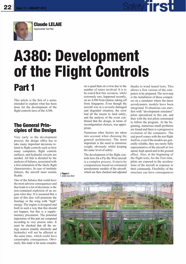
structure can have consequencesFigure 1 A380 Iron Bird
22 Issue 13 | JANUARY 2012 Safety
8/12/2019 Airbus Safety First Mag - Jan 2012
http://slidepdf.com/reader/full/airbus-safety-first-mag-jan-2012 23/34
on comfort, but can also induce
effects on the flying characteris-
tics.Often, the models used for
computations or in the simula-tor are correct so that after tun-
ing on ground and validation in
flight, there is nothing else to
do. But it occasionally happens
that the aircraft behaviour is not
in line with the expectations and
an aerodynamic identification in
flight is needed to allow further
tuning of the models in order to
enable the design office to define
the next standard of the comput-
ers. Sometimes it is difficult be-
cause the modelling of the groundeffect is not satisfactory or the
flexibility of the aircraft does not
permit a correct simulation. In
this case, the development has to
be performed in two phases, f irst
with models and then directly in
flight. When in flight, engineers
and pilots decide in real time
what adjustments are necessary.
They are using their knowledge,
judgement, common sense and
feelings (seat of the pants flying).
Some non-specialists considerthat the flight test task is only
to validate results obtained in a
simulator. This is not correct, as,
for a significant number of tests,
methodologies have not evolved
since the last century, except for
the help given by the computers.
Most of the time, qualitative
feelings and impressions are still
showing the way.
In order to save time, the flight
test engineers have a tool called
AFDX Digital Injection System
(ADIS), which allows them to
modify in real time some char-
acteristics of the computers. For
safety reasons, all the new pos-
sible adjustments are checked in
a simulator before using them in
flight.
The development of the flight
controls laws is a fascinating ad-
venture: every day there are new
surprises, some good and some
bad. The A380 has not been the
most difficult aircraft in this re-
spect, thanks to the excellent aer-
odynamic characteristics.
Fly-By-Wireand AssociatedImprovementsFly-By-Wire has brought a lot to
aviation. Obviously the ease of
flying and the protections to avoid
loss of control are well known, but
that is not all.
In the past, flight controls were
designed to meet two sets of criteria:
they had to be “well harmonised”
and had to meet the criteria for cer-
tification. With Fly-By-Wire, three
possibilities have been added: im- prove safety by restricting manoeu-
vres which could lead to a loss of
control, reduce the weight of the
structure with the prohibition of
some actions, which may increase
the loads and finally improve com-
fort for the passengers. Adding all
these functions leads to more and
more complexity for the flight con-
trols computers.
The Main A380Characteristics
A general description of the main
characteristics of the A380 flight
controls will allow us to gain a better
understanding of the tests performed.
The A380 has seven flight controls
computers: three Primary Com-
puters (PRIMs), three Secondary
Computers (SECs), and one Back
Up Control Module (BCM). Any
of the three PRIMs can ensure the
full control of the plane without re-
striction. The SECs do not providestabilized control laws as do the
PRIMs but they are more robust to
the loss of some information. They
also have different software than
the PRIMs so that a bug in one cat-
egory of computer does not “con-
taminate” the others. All computers
have a command and a monitoring
lane. Finally, there is a BCM, avail-
able in case of failure of all PRIMs
and SECs.
The A380 has only two hydraulic cir-cuits instead of three on the Airbus of
the previous generations. The third
circuit has been replaced by local
hydraulic generation: for some ser-
vo-controls, a small electrical mo-
tor creates the hydraulic energy to
power it. These systems are called
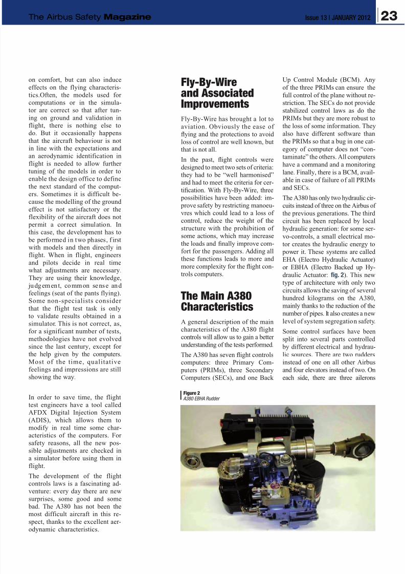
EHA (Electro Hydraulic Actuator)
or EBHA (Electro Backed up Hy-
draulic Actuator: fig. 2). This new
type of architecture with only two
circuits allows the saving of several
hundred kilograms on the A380,
mainly thanks to the reduction of the
number of pipes. It also creates a new
level of system segregation safety.
Some control surfaces have been
split into several parts controlled
by different electrical and hydrau-
lic sources. There are two rudders
instead of one on all other Airbus
and four elevators instead of two. On
each side, there are three ailerons
Figure 2 A380 EBHA Rudder
23Issue 13 | JANUARY 2012The Airbus Safety Magazine
8/12/2019 Airbus Safety First Mag - Jan 2012
http://slidepdf.com/reader/full/airbus-safety-first-mag-jan-2012 24/34
instead of one on the A320 family and
two on the A340 and A330. Each of
the surfaces (except the spoilers) is
activated by two servos using dif-
ferent hydraulic circuits or EHA or
EBHA. Two or three different com-
puters (PRIM and SEC plus BCM)
control each of the servos. Therefore,
a lot of failures are needed to lose
the control of one surface.
When the four engines (or their gen-
erators) and the APU are no longer
available, electricity is coming from
a Ram Air Turbine (RAT).
The Identificationof the Aircraft
To ensure that the adjustments to
the control laws are well adapted
to the characteristics of the plane,
the design office needs a good
aerodynamic model. This is ini-
tially achieved through simulation.
However some tuning can only be
finalized and validated in flight.
So, the identification of the aircraft
stability and control characteristics
in flight is among the first priorities
of the program. On the A380, about
one month after the beginning of
the flight tests, in April 2005, flight
16 was devoted to identification
of these characteristics in pitch.
Then, during the months of July and
August, about 15 flights were dedi-
cated to similar tests in roll, pitch,
effect of the engines… More were
performed during the following
months.These identification flights are
completely different from those
which must be done at the end of
the development in order to prepare
the aircraft models for installation
in the training simulators. For these
last flights a very specific process
has to be followed. The training
simulators do not need to represent
the flight characteristics in extreme
situations. On the other hand, in
order to develop the flight control
computers, the design office needs
to have a good identification of the
aerodynamic characteristics at the
limits of the flight envelope.
The Take-OffRotation Law
On the A340-600, the development
of the take-off control law proved
to be rather difficult. It is worth ex-
plaining the issue here to show the
kind of obstacles that can be found.
All the pilots agreed that, on the
A340-300, the reaction in pitch
during the rotation at take-off,
whilst being acceptable, was a bit
sluggish. As the A340-600 was
planned to be about 100 tons heavier
than the A340-300 and longer
by about 12 meters, a s tudy waslaunched to improve the reaction of
the -600 during the rotation. Nu-
merous tests were performed in the
simulator and then the new control
law was installed on the A340-300
used for development. The team
was happy with the results. Sub-
sequently, the take-offs of the first
two flights of the A340-600 were
performed in direct law in order to
improve progressively our knowl-
edge of the aircraft. Following the
landing from the second flight, itwas planned to perform another
take-off with the brand new rota-
tion law. It just happened that the
Captain of the A340-600 had been
in charge of the development of
this law. At the beginning of the
manoeuvre, the aircraft exhibited
a strong Pilot Induced Oscillation
(PIO). The pilot reacted naturally
to an unexpectedly strong response
of the aircraft. The oscillations
stopped after six cycles.
Why this surprise, as everythingwas well prepared? The forward
part of the A340-600 is longer than
on the -300 and, with this lever,
the crew had the feeling of being
projected too quickly into the air
and therefore reacted immediately,
creating this PIO. All the work done
prior to the flight could not be used
as such. So, after a minimum of
development in the simulator,
to have a good starting point for
the control law, the tuning was
performed during a flight witharound 15 take-offs.
The principle is rather simple: with
the help of the ADIS, at each take-
off, it is possible to improve what
the pilots are feeling and the flight
engineers have on their traces. As
an example, the law can be mademore or less efficient at the initial
pilot command. It is also possible
to reduce the pitch rate when ap-
proaching the take-off attitude,
but not too early and not too late.
If there is a risk of tail strike, the
pitch rate must also be controllable
to almost zero very quickly. The
flight test engineers have to play
with a lot of variables such as pre-
command, damping, filtering and
so on, so as to reduce the take-off
distances and ensure safety in allthe critical cases such as engine
failure, early rotation… To perform
this tuning well they must have a
perfect understanding of the effect
of all parameters.
This example shows the limits of
what is possible to perform with
models or with the simulation for
some flight phases, particularly
close to the ground. However, the
conclusion must not be that models
have to be disregarded. Very good
preparation is fundamental in order
to have a solid starting point and
to give to the flight test engineers
well-adapted tools with the ADIS.
After the lessons of the A340-600,
we decided to keep the same meth-
odology to develop the rotation law
of the A380: a basic and simple
preparation using models and simu-
lators followed by the development
with flight tests.
For all these tests: development of arotation law and, later on, measure-
ments of take-off distances, there is
always a risk of tail strike because
we are frequently on the limit of
manoeuvrability of the aircraft.
Therefore, the aircraft is equipped
with a tail bumper, the same that is
used for the VMU tests.
The first flight for development of
the A380 take-off rotation law was
performed on December 29th 2005
with a very experienced crew: two
test pilots, one test flight engineer
(in the cockpit) and two flight test
engineers both specialists of flight
controls. After 15 take-offs, the
24 Issue 13 | JANUARY 2012 Safety
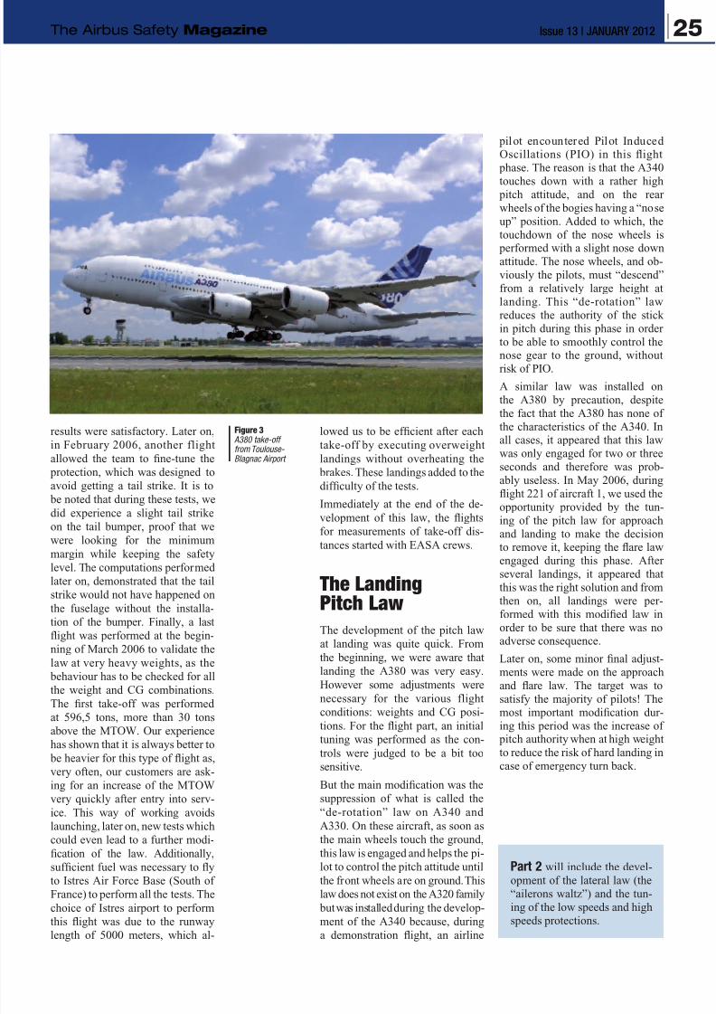
8/12/2019 Airbus Safety First Mag - Jan 2012
http://slidepdf.com/reader/full/airbus-safety-first-mag-jan-2012 25/34
results were satisfactory. Later on,
in February 2006, another flight
allowed the team to fine-tune the
protection, which was designed to
avoid getting a tail strike. It is to
be noted that during these tests, we
did experience a slight tail strike
on the tail bumper, proof that we
were looking for the minimum
margin while keeping the safety
level. The computations performed
later on, demonstrated that the tail
strike would not have happened on
the fuselage without the installa-
tion of the bumper. Finally, a last
flight was performed at the begin-
ning of March 2006 to validate the
law at very heavy weights, as the
behaviour has to be checked for all
the weight and CG combinations.
The first take-off was performed
at 596,5 tons, more than 30 tons
above the MTOW. Our experience
has shown that it is always better to
be heavier for this type of flight as,
very often, our customers are ask-
ing for an increase of the MTOW
very quickly after entry into serv-
ice. This way of working avoids
launching, later on, new tests which
could even lead to a further modi-
fication of the law. Additionally,
sufficient fuel was necessary to fly
to Istres Air Force Base (South of
France) to perform all the tests. The
choice of Istres airport to perform
this flight was due to the runway
length of 5000 meters, which al-
lowed us to be efficient after each
take-off by executing overweight
landings without overheating the
brakes. These landings added to the
difficulty of the tests.
Immediately at the end of the de-
velopment of this law, the flights
for measurements of take-off dis-tances started with EASA crews.
The LandingPitch Law
The development of the pitch law
at landing was quite quick. From
the beginning, we were aware that
landing the A380 was very easy.
However some adjustments were
necessary for the various flight
conditions: weights and CG posi-tions. For the flight part, an initial
tuning was performed as the con-
trols were judged to be a bit too
sensitive.
But the main modification was the
suppression of what is called the
“de-rotation” law on A340 and
A330. On these aircraft, as soon as
the main wheels touch the ground,
this law is engaged and helps the pi-
lot to control the pitch attitude until
the front wheels are on ground. This
law does not exist on the A320 family
but was installed during the develop-
ment of the A340 because, during
a demonstration flight, an airline
pilot encountered Pilot InducedOscillations (PIO) in this flight
phase. The reason is that the A340
touches down with a rather high pitch attitude, and on the rear
wheels of the bogies having a “nose
up” position. Added to which, the
touchdown of the nose wheels is performed with a slight nose down
attitude. The nose wheels, and ob-
viously the pilots, must “descend”
from a relatively large height at
landing. This “de-rotation” law
reduces the authority of the stick
in pitch during this phase in order
to be able to smoothly control the
nose gear to the ground, withoutrisk of PIO.
A similar law was installed on
the A380 by precaution, despite
the fact that the A380 has none of
the characteristics of the A340. Inall cases, it appeared that this law
was only engaged for two or three
seconds and therefore was prob-
ably useless. In May 2006, during
flight 221 of aircraft 1, we used the
opportunity provided by the tun-
ing of the pitch law for approach
and landing to make the decisionto remove it, keeping the flare law
engaged during this phase. After
several landings, it appeared that
this was the right solution and from
then on, all landings were per-
formed with this modified law in
order to be sure that there was noadverse consequence.
Later on, some minor final adjust-
ments were made on the approach
and flare law. The target was to
satisfy the majority of pilots! The
most important modification dur-ing this period was the increase of
pitch authority when at high weight
to reduce the risk of hard landing in
case of emergency turn back.
Part 2 will include the devel-
opment of the lateral law (the
“ailerons waltz”) and the tun-
ing of the low speeds and high
speeds protections.
Figure 3 A380 take-offfrom Toulouse- Blagnac Airport
25Issue 13 | JANUARY 2012The Airbus Safety Magazine

8/12/2019 Airbus Safety First Mag - Jan 2012
http://slidepdf.com/reader/full/airbus-safety-first-mag-jan-2012 26/34
Uwe EGGERLINGSafety DirectorEngineering & MaintenanceCustomer Services
Facing the Reality ofEveryday Maintenance
OperationsThe aviation maintenance environ-
ment is a challenging working place.Mechanics work in physically de-
manding conditions, such as high
above the ground in the aircraft
structure, or in small confined sur-
roundings. They can be exposed to
high or low temperatures, and to
demanding shift work.
There is an increasing workload
and time pressure to get the aircraft
back into service as quickly as pos-
sible after maintenance. Aircraft
maintenance requires mechanics
to follow procedures by the letter,
ensure good communication, diag-
nose and fix problems under time
pressure, read and record various
data, and continuously adapt to
new technologies.
The Safety First magazine will
dedicate a number of articles to the
field of maintenance.The objective is to share the lessons
learned and experience reported from
the Airbus fleet. It will also ra ise
awareness, and provide recom-
mendations for safe maintenance
operations.
2. Brief EventsDescription
The following two events are rep-
resentative of a number of similar
hazardous engine removal/ installa-
tion incidents:q On the first occurrence, one of
the bootstraps failed, causing an
engine to drop by a distance of
three feet (fig. 1).
q On the second event, an engine
fell to the ground during its removal.
The forward left chain pulley disen-
gaged while the maintenance team
was performing Aircraft Main-
tenance Manual (AMM) subtask
71-00-00-020-053-A(fig. 2).
The reported problems in the use
of the engine tools (the bootstrap),
are not related to any one particular
Airbus type.The majority of these
incidents are the consequence of
one, or a combination of the fol-
lowing reasons:
q Use of tools not listed in the
AMM, and not approved by Airbus.
q
Not using appropriately main-tained tools.
q A too high pre-load applied to the
tool, which can damage the tool.
1. Introduction
Most maintenance engineers canremember cases where the use of
a wrong, or inappropriate tool, has
contributed to difficulties in main-
tenance operations. In most cases,
this has lead to additional incurredcosts, but on certain occurrences
this has even represented a poten-
tial threat for the safety of mainte-
nance personnel.
The absence of reliable statisticalfigures in how often specific main-
tenance tools have been involved
in maintenance errors can be ex-
plained by the fact that there are no
specific reporting requirements for
maintenance events involving toolsas being at the origin of the event.
The consequences resulting fromthe use of wrong, or inappropriate
tools, are not always immediately
evident in terms of aircraft dispatch
indicators, and, even when they are,
they may not have been reported as
the origin of the event.
This article will cover the subject
of tooling issues related to engine
removal and installation proce-
dures. However, the points raised
here are illustrative as well of other
maintenance operations.
26 Issue 13 | JANUARY 2012 Safety
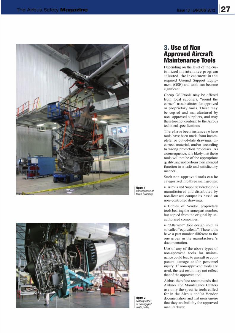
8/12/2019 Airbus Safety First Mag - Jan 2012
http://slidepdf.com/reader/full/airbus-safety-first-mag-jan-2012 27/34
3. Use of Non Approved AircraftMaintenance ToolsDepending on the level of the cus-tomized maintenance prog ram
selected, the investment in the
required Ground Support Equip-ment (GSE) and tools can become
significant.
Cheap GSE/tools may be offeredfrom local suppliers, “round the
corner”, as substitutes for approved
or proprietary tools. These may
be copied and manufactured by
non- approved suppliers, and maytherefore not conform to the Airbus
technical specifications.
There have been instances where
tools have been made from incom-
plete, or out-of-date drawings, in-
correct material, and/or accordingto wrong protection processes. As
a consequence, it is likely that these
tools will not be of the appropriatequality, and not perform their intended
function in a safe and satisfactory
manner.
Such non-approved tools can be
categorized into three main groups:
q Airbus and Supplier/Vendor tools
manufactured and distributed by
non-licensed companies based onnon–controlled drawings.
q Copies of Vendor proprietary
tools bearing the same part number, but copied from the original by un-
authorized companies.
q “Alternate” tool design sold as
so-called “equivalents”. These tools
have a part number different to theone given in the manufacturer’s
documentation.
Use of any of the above types of
non-approved tools for mainte-
nance could lead to aircraft or com-
ponent damage and/or personnelinjury. If non-approved tools are
used, the test result may not reflect
that of the approved tool.
Airbus therefore recommends that
Airlines and Maintenance Centers
use only the specific tools calledfor in the Airbus and/or Vendor
documentation, and that users ensure
that they are built by the approved
manufacturer.
Figure 1Consequence offailed bootstrap
Figure 2consequenceof disengagedchain pulley
27Issue 13 | JANUARY 2012The Airbus Safety Magazine
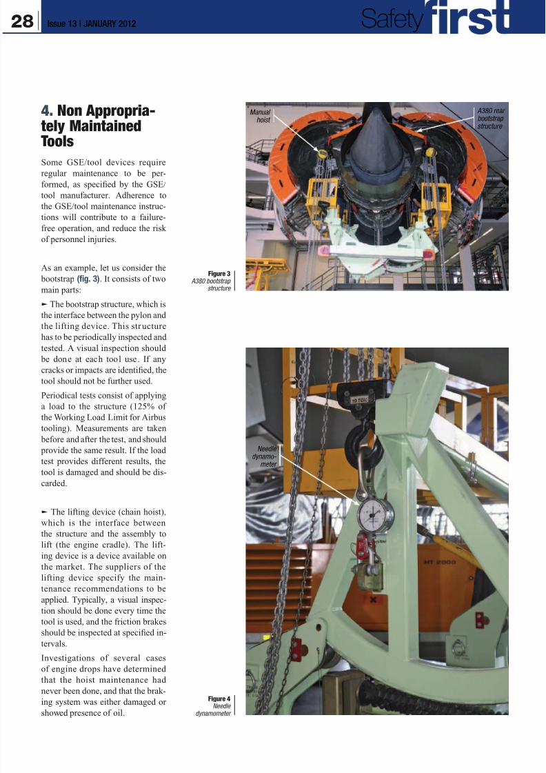
8/12/2019 Airbus Safety First Mag - Jan 2012
http://slidepdf.com/reader/full/airbus-safety-first-mag-jan-2012 28/34
A380 rearbootstrapstructure
Manualhoist
Needledynamo-
meter
Figure 4Needle
dynamometer
Figure 3 A380 bootstrap
structure
4. Non Appropria-tely Maintained
Tools
Some GSE/tool devices require
regular maintenance to be per-
formed, as specified by the GSE/
tool manufacturer. Adherence to
the GSE/tool maintenance instruc-
tions will contribute to a failure-
free operation, and reduce the risk
of personnel injuries.
As an example, let us consider the bootstrap (fig. 3). It consists of two
main parts:
q The bootstrap structure, which is
the interface between the pylon and
the lifting device. This structure
has to be periodically inspected and
tested. A visual inspection should
be done at each tool use. If any
cracks or impacts are identified, the
tool should not be further used.
Periodical tests consist of applying
a load to the structure (125% ofthe Working Load Limit for Airbus
tooling). Measurements are taken
before and after the test, and should
provide the same result. If the load
test provides different results, the
tool is damaged and should be dis-
carded.
q The lifting device (chain hoist),
which is the interface between
the structure and the assembly to
lift (the engine cradle). The lift-
ing device is a device available on
the market. The suppliers of the
lifting device specify the main-
tenance recommendations to be
applied. Typically, a visual inspec-
tion should be done every time the
tool is used, and the friction brakes
should be inspected at specified in-
tervals.
Investigations of several cases
of engine drops have determined
that the hoist maintenance had
never been done, and that the brak-
ing system was either damaged or
showed presence of oil.
28 Issue 13 | JANUARY 2012 Safety
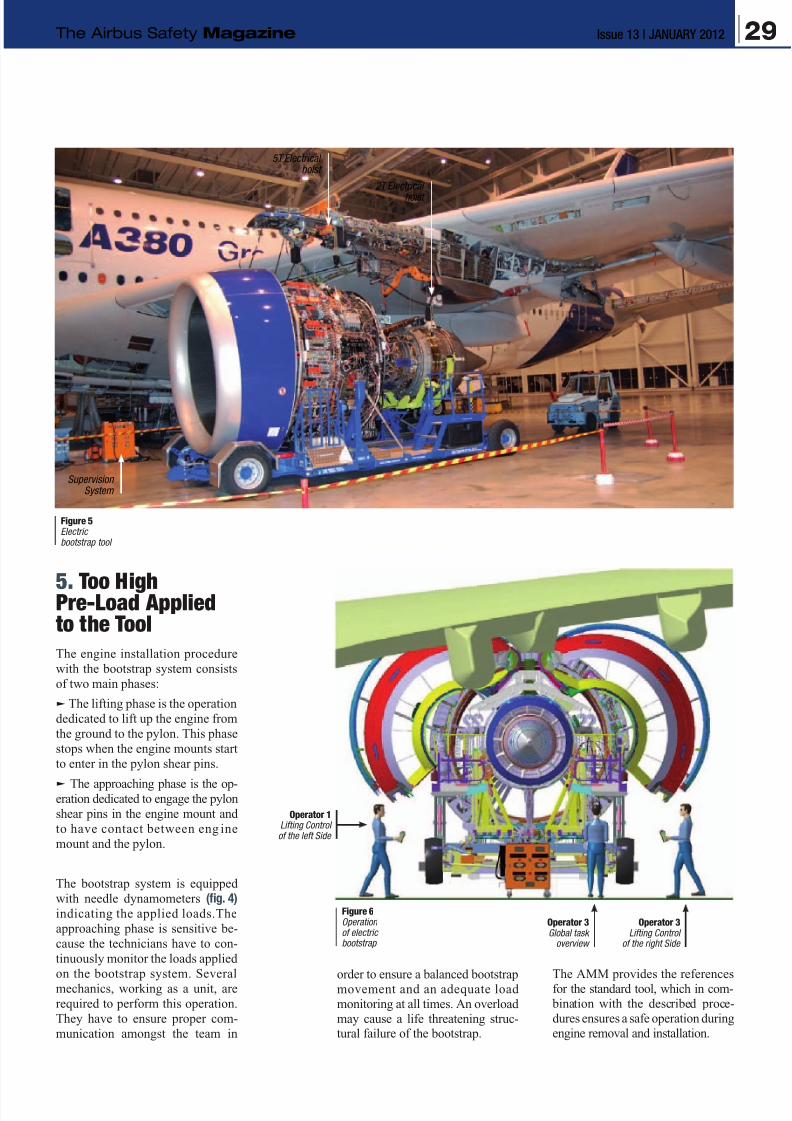
8/12/2019 Airbus Safety First Mag - Jan 2012
http://slidepdf.com/reader/full/airbus-safety-first-mag-jan-2012 29/34
order to ensure a balanced bootstrap
movement and an adequate load
monitoring at all times. An overload
may cause a life threatening struc-tural failure of the bootstrap.
The AMM provides the references
for the standard tool, which in com-
bination with the described proce-
dures ensures a safe operation during
engine removal and installation.
5. Too HighPre-Load Appliedto the Tool
The engine installation procedure
with the bootstrap system consists
of two main phases:
q The lifting phase is the operation
dedicated to lift up the engine from
the ground to the pylon. This phase
stops when the engine mounts start
to enter in the pylon shear pins.
q The approaching phase is the op-
eration dedicated to engage the pylon
shear pins in the engine mount and
to have contact between eng ine
mount and the pylon.
The bootstrap system is equipped
with needle dynamometers (fig. 4)
indicating the applied loads.The
approaching phase is sensitive be-
cause the technicians have to con-
tinuously monitor the loads applied
on the bootstrap system. Several
mechanics, working as a unit, are
required to perform this operation.
They have to ensure proper com-
munication amongst the team in
5T Electricalhoist
SupervisionSystem
2T Electrical
hoist
Operator 3Global task
overview
Operator 3Lifting Control
of the right Side
Figure 6Operationof electricbootstrap
Operator 1Lifting Controlof the left Side
Figure 5Electricbootstrap tool
29Issue 13 | JANUARY 2012The Airbus Safety Magazine
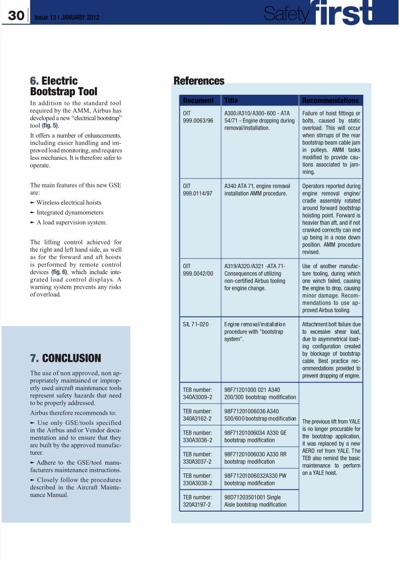
8/12/2019 Airbus Safety First Mag - Jan 2012
http://slidepdf.com/reader/full/airbus-safety-first-mag-jan-2012 30/34
References6. ElectricBootstrap ToolIn addition to the standard tool
required by the AMM, Airbus has
developed a new “electrical bootstrap”
tool (fig. 5).
It offers a number of enhancements,including easier handling and im-
proved load monitoring, and requires
less mechanics. It is therefore safer to
operate.
The main features of this new GSEare:
q Wireless electrical hoists
q Integrated dynamometers
q A load supervision system.
The lifting control achieved for
the right and left hand side, as well
as for the forward and aft hoists
is performed by remote control
devices (fig. 6), which include inte-
grated load control displays. Awarning system prevents any risks
of overload.
7. CONCLUSION
The use of non approved, non ap- propriately maintained or improp-
erly used aircraft maintenance tools
represent safety hazards that needto be properly addressed.
Airbus therefore recommends to:
q Use only GSE/tools specifiedin the Airbus and/or Vendor docu-
mentation and to ensure that they
are built by the approved manufac-
turer.
q Adhere to the GSE/tool manu-
facturers maintenance instructions.
q Closely follow the procedures
described in the Aircraft Mainte-
nance Manual.
Document Title Recommendations
OIT
999.0063/96
A300/A310/A300-600 - ATA
54/71 - Engine dropping during
removal/installation.
Failure of hoist fittings or
bolts, caused by static
overload. This will occur
when stirrups of the rear
bootstrap beam cable jam
in pulleys. AMM tasks
modified to provide cau-
tions associated to jam-
ming.
OIT
999.0114/97
A340 ATA 71, engine removal
installation AMM procedure.
Operators reported during
engine removal engine/
cradle assembly rotated
around forward bootstrap
hoisting point. Forward is
heavier than aft, and if not
cranked correctly can end
up being in a nose down
position. AMM procedure
revised.
OIT
999.0042/00
A319/A320 /A321 -ATA 71-
Consequences of utilizing
non-certified Airbus tooling
for engine change.
Use of another manufac-
ture tooling, during which
one winch failed, causing
the engine to drop, causing
minor damage. Recom-mendations to use ap-
proved Airbus tooling.
SIL 71-020 Engine removal/installation
procedure with "bootstrap
system".
Attachment bolt failure due
to excessive shear load,
due to asymmetrical load-
ing configuration created
by blockage of bootstrap
cable. Best practice rec-
ommendations provided to
prevent dropping of engine.
TEB number:
340A3009-2
98F71201000 021 A340
200/300 bootstrap modification
The previous lift from YALE
is no longer procurable for
the bootstrap application,
it was replaced by a new
AERO ref from YALE. The
TEB also remind the basic
maintenance to perform
on a YALE hoist.
TEB number:
340A3162-2
98F71201006036 A340
500/600 bootstrap modification
TEB number:
330A3036-2
98F71201006034 A330 GE
bootstrap modification
TEB number:
330A3037-2
98F71201006030 A330 RR
bootstrap modification
TEB number:
330A3038-2
98F71201006032A330 PW
bootstrap modification
TEB number:
320A3197-2
98D71203501001 Single
Aisle bootstrap modification
30 Issue 13 | JANUARY 2012 Safety
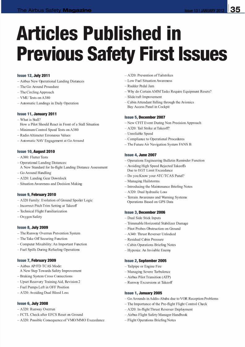
8/12/2019 Airbus Safety First Mag - Jan 2012
http://slidepdf.com/reader/full/airbus-safety-first-mag-jan-2012 31/34
Issue 12, July 2011
– Airbus New Operational Landing Distances
– The Go Around Procedure
– The Circling Approach
– VMU Tests on A380
– Automatic Landings in Daily Operation
Issue 11, January 2011
– What is Stall?How a Pilot Should React in Front of a Stall Situation
– Minimum Control Speed Tests on A380
– Radio Altimeter Erroneous Values
– Automatic NAV Engagement at Go Around
Issue 10, August 2010
– A380: Flutter Tests
– Operational Landing Distances:
A New Standard for In-flight Landing Distance Assessment
– Go Around Handling
– A320: Landing Gear Downlock
– Situation Awareness and Decision Making
Issue 9, February 2010
– A320 Family: Evolution of Ground Spoiler Logic
– Incorrect Pitch Trim Setting at Takeoff
– Technical Flight Familiarization
– Oxygen Safety
Issue 8, July 2009
– The Runway Overrun Prevention System
– The Take Off Securing Function
– Computer Mixability: An Important Function
– Fuel Spills During Refueling Operations
Issue 7, February 2009
– Airbus AP/FD TCAS Mode:
A New Step Towards Safety Improvement
– Braking System Cross Connections
– Upset Recovery Training Aid, Revision 2
– Fuel Pumps Left in OFF Position
– A320: Avoiding Dual Bleed Loss
Issue 6, July 2008 – A320: Runway Overrun
– FCTL Check after EFCS Reset on Ground
– A320: Possible Consequence of VMO/MMO Exceedance
– A320: Prevention of Tailstrikes
– Low Fuel Situation Awareness
– Rudder Pedal Jam
– Why do Certain AMM Tasks Require Equipment Resets?
– Slide/raft Improvement
– Cabin Attendant Falling through the Avionics
Bay Access Panel in Cockpit
Issue 5, December 2007
– New CFIT Event During Non Precision Approach
– A320: Tail Strike at Takeoff?
– Unreliable Speed
– Compliance to Operational Procedures
– The Future Air Navigation System FANS B
Issue 4, June 2007
– Operations Engineering Bulletin Reminder Function
– Avoiding High Speed Rejected Takeoffs
Due to EGT Limit Exceedance
– Do you Know your ATC/TCAS Panel?
– Managing Hailstorms – Introducing the Maintenance Briefing Notes
– A320: Dual hydraulic Loss
– Terrain Awareness and Warning Systems
Operations Based on GPS Data
Issue 3, December 2006
– Dual Side Stick Inputs
– Trimmable Horizontal Stabilizer Damage
– Pitot Probes Obstruction on Ground
– A340: Thrust Reverser Unlocked
– Residual Cabin Pressure
– Cabin Operations Briefing Notes
– Hypoxia: An Invisible Enemy
Issue 2, September 2005
– Tailpipe or Engine Fire
– Managing Severe Turbulence
– Airbus Pilot Transition (ATP)
– Runway Excursions at Takeoff
Issue 1, January 2005
– Go Arounds in Addis-Ababa due to VOR Reception Problems
– The Importance of the Pre-flight Flight Control Check – A320: In-flight Thrust Reverser Deployment
– Airbus Flight Safety Manager Handbook
– Flight Operations Briefing Notes
Articles Published in
Previous Safety First Issues
35Issue 13 | JANUARY 2012The Airbus Safety Magazine

8/12/2019 Airbus Safety First Mag - Jan 2012
http://slidepdf.com/reader/full/airbus-safety-first-mag-jan-2012 32/34
Subscription Form
Safety
8/12/2019 Airbus Safety First Mag - Jan 2012
http://slidepdf.com/reader/full/airbus-safety-first-mag-jan-2012 33/34
The Airbus Safety Magazine
Subscription Form To be sent back to
AIRBUS FLIGHT SAFETY OFFICE
Fax: 33 (0)5 61 93 44 29
Mail to: [email protected]
Name . . . . . . . . . . . . . . . . . . . . . . . . . . . . . . . . . . . . . . . . . . . . . . . . . . . . . . . . . . . . . . . . . . . . . . . . . . . . . . . . . . . . . . . . .
Surname . . . . . . . . . . . . . . . . . . . . . . . . . . . . . . . . . . . . . . . . . . . . . . . . . . . . . . . . . . . . . . . . . . . . . . . . . . . . . . . . . . . . . . .
Job title/Function. . . . . . . . . . . . . . . . . . . . . . . . . . . . . . . . . . . . . . . . . . . . . . . . . . . . . . . . . . . . . . . . . . . . . . . . . . . . . . . . .
Company/Organization. . . . . . . . . . . . . . . . . . . . . . . . . . . . . . . . . . . . . . . . . . . . . . . . . . . . . . . . . . . . . . . . . . . . . . . . . . . . .
Address . . . . . . . . . . . . . . . . . . . . . . . . . . . . . . . . . . . . . . . . . . . . . . . . . . . . . . . . . . . . . . . . . . . . . . . . . . . . . . . . . . . . . . . .
. . . . . . . . . . . . . . . . . . . . . . . . . . . . . . . . . . . . . . . . . . . . . . . . . . . . . . . . . . . . . . . . . . . . . . . . . . . . . . . . . . . . . . . . . . . . . .
. . . . . . . . . . . . . . . . . . . . . . . . . . . . . . . . . . . . . . . . . . . . . . . . . . . . . . . . . . . . . . . . . . . . . . . . . . . . . . . . . . . . . . . . . . . . . .
Post/Zip Code . . . . . . . . . . . . . . . . . . . . . . . . . . . . . . . . . . . . . . . . . . . . . . . . . . . . . . . . . . . . . . . . . . . . . . . . . . . . . . . . . . .
Country . . . . . . . . . . . . . . . . . . . . . . . . . . . . . . . . . . . . . . . . . . . . . . . . . . . . . . . . . . . . . . . . . . . . . . . . . . . . . . . . . . . . . . . .
Telephone . . . . . . . . . . . . . . . . . . . . . . . . . . . . . . . . . . . . . . . . . . . . . . . . . . . . . . . . . . . . . . . . . . . . . . . . . . . . . . . . . . . . . .
Cell phone . . . . . . . . . . . . . . . . . . . . . . . . . . . . . . . . . . . . . . . . . . . . . . . . . . . . . . . . . . . . . . . . . . . . . . . . . . . . . . . . . . . . . .
Fax . . . . . . . . . . . . . . . . . . . . . . . . . . . . . . . . . . . . . . . . . . . . . . . . . . . . . . . . . . . . . . . . . . . . . . . . . . . . . . . . . . . . . . . . . . .
E-mail . . . . . . . . . . . . . . . . . . . . . . . . . . . . . . . . . . . . . . . . . . . . . . . . . . . . . . . . . . . . . . . . . . . . . . . . . . . . . . . . . . . . . . . . . . . . . . . . . .
(Mandatory for both digital and paper copies)
Please send me the digital copy* P
Please send me the paper copy* P (Please note that paper copieswill only be forwardedto professional addresses)
* Please tick the appropriate case
Safety

8/12/2019 Airbus Safety First Mag - Jan 2012
http://slidepdf.com/reader/full/airbus-safety-first-mag-jan-2012 34/34