aircraft design introduction to structure life - uliege · total life design • design with...
TRANSCRIPT

University of Liège
Aerospace & Mechanical Engineering
Aircraft Design
Introduction to Structure Life
Aircraft Design – Structure Life
Ludovic Noels
Computational & Multiscale Mechanics of Materials – CM3
http://www.ltas-cm3.ulg.ac.be/
Chemin des Chevreuils 1, B4000 Liège
Total life design
• Design with stresses lower than
– Elastic limit (sp0) or
– Tensile strength (sTS)
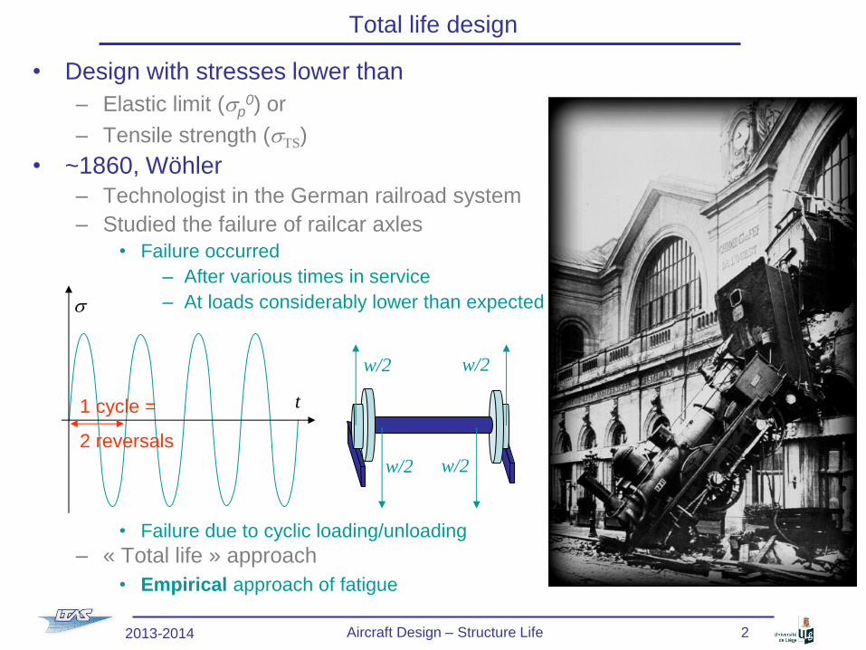
• ~1860, Wöhler
– Technologist in the German railroad system
– Studied the failure of railcar axles
• Failure occurred
– After various times in service
– At loads considerably lower than expected
• Failure due to cyclic loading/unloading
– « Total life » approach
• Empirical approach of fatigue
w/2 w/2
w/2 w/2
t
s
1 cycle =
2 reversals
2013-2014 Aircraft Design – Structure Life 2

Total life design
• Empirical approach: Total life
– Life of a structure depends on
• Minimal & maximal stresses: smin & smax
• Mean stress: sm=(smax + smin)/2
• Amplitude: sa = Ds/2 = (smax - smin)/2
• Load Ratio: R = smin / smax
• Under particular environmental conditions (humidity, high temperature, …):
– Frequency of cycles
– Shape of cycles (sine, step, …)
t
smax
smin
Ds = smax-smin
sa = Ds/2
sm
1 cycle =
2 reversals
2013-2014 Aircraft Design – Structure Life 3

Total life design
• First kind of total life approach: « stress life » approach
– For structures experiencing (essentially) elastic deformations
– For sm = 0 & Nf identical cycles before failure
• For sa < se (endurance limit):
infinite life (>107 cycles)
• For sa > se, finite life
• With se ~ [ 0.35 ; 0.5 ] sTS
• 1910, Basquin Law
– sf’ fatigue coefficient (mild steel Tamb : ~ [1; 3 ] GPa)
– b fatigue exponent (mild steel Tamb : ~ [-0.1; -0.06])
– Parameters resulting from experimental tests
Nf
se
sa = Ds/2
103 104 105 106 107
2013-2014 Aircraft Design – Structure Life 4

Total life design
• First kind of total life approach: « stress life » approach (2)
– For sm ≠ 0 and Nf identical cycles, the maximal amplitude is corrected
• Soderberg conservative
• Goodman
• Gerber only for alloys under tension
– Varying amplitude loads
• ni cycles of constant amplitude
lead to a damage
• 1945, Miner-Palmgren law
– Does not account for the sequence in which the cycles are applied
t
sa1,
sm1
n1 n2
sa2, sm2
s
2013-2014 Aircraft Design – Structure Life 5

Total life design
• Second kind of total life approach: « strain life » approach
– For structures experiencing (essentially)
• Large plastic deformations
• Stress concentration
• High temperatures
– For Nf identical cycles before failure
• 1954, Manson-Coffin
– ef’ : fatigue ductility coefficient ~ true fracture ductility (metals)
– c : fatigue ductility coefficient exponent ~ [-0.7 , -0.5] (metals)
– plastic strain increment during the loading cycles
2013-2014 Aircraft Design – Structure Life 6

Design using total life approach
• 1952, De Havilland 106 Comet 1, UK (1)
– First jetliner, 36 passengers, pressurized cabin (0.58 atm)
– Wrong aerodynamics at high angle of attack (takeoff)
• 1953, 2 crashes: lift loss due to swept wing and air intakes inefficient
– The fuselage was designed using total life approach
• 1952, a fuselage was tested against fatigue
– Static loading at 1.12 atm, followed by
– 10 000 cycles at 0.7 atm (> cabin pressurization at 0.58 atm)
– Design issue • 1953, India, crash during storm
– « Structural failure » of the stabilizer
– The pilot does not “feel” the forces due to the fully powered controls (hydraulically assisted)
– Fatigue due to overstress ?
2013-2014 Aircraft Design – Structure Life 7
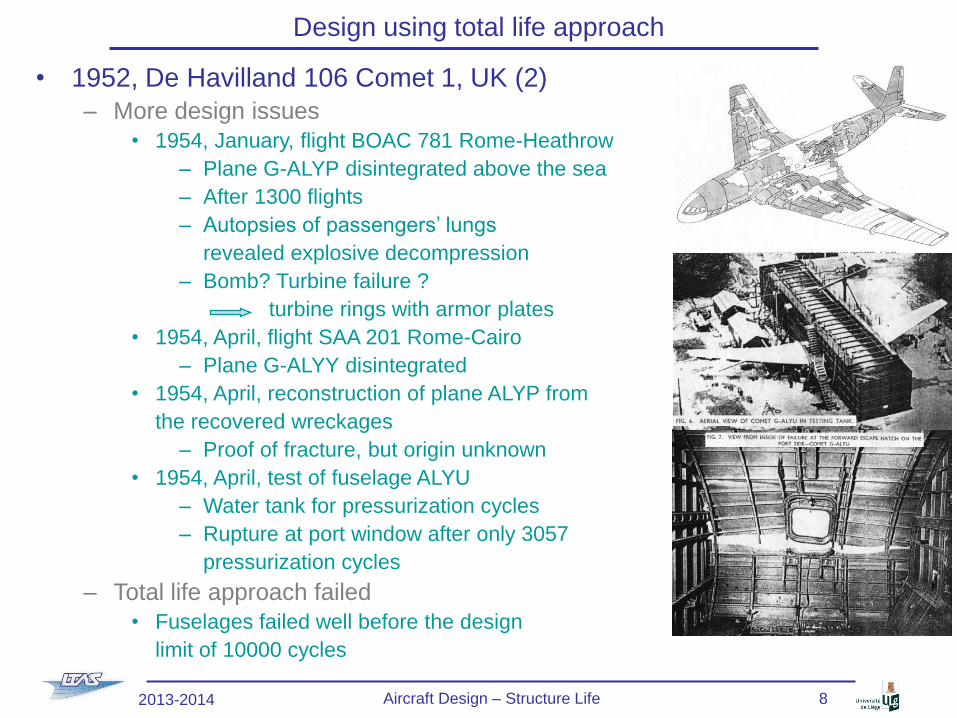
• 1952, De Havilland 106 Comet 1, UK (2)
– More design issues
• 1954, January, flight BOAC 781 Rome-Heathrow
– Plane G-ALYP disintegrated above the sea
– After 1300 flights
– Autopsies of passengers’ lungs
revealed explosive decompression
– Bomb? Turbine failure ?
turbine rings with armor plates
• 1954, April, flight SAA 201 Rome-Cairo
– Plane G-ALYY disintegrated
• 1954, April, reconstruction of plane ALYP from
the recovered wreckages
– Proof of fracture, but origin unknown
• 1954, April, test of fuselage ALYU
– Water tank for pressurization cycles
– Rupture at port window after only 3057
pressurization cycles
– Total life approach failed
• Fuselages failed well before the design
limit of 10000 cycles
Design using total life approach
2013-2014 Aircraft Design – Structure Life 8

• 1952, De Havilland 106 Comet 1, UK (3) – 1954, August, ALYP roof retrieved from sea
• Origin of failure at the communication window
• Use of square riveted windows
• Punched riveting instead of drill riveting
Existence of initial defects
• The total life approach
– Accounts for crack initiation in smooth specimen
– Does not account for inherent defects
• Metal around initial defects could have hardened during the initial static test load
of the fatigue tested fuselage
• Production planes without this static test load …
• Life time can be improved by – “Shoot peening”: surface bombarded by small spherical media
• Compression residual stresses in the surface layer
• Prevents crack initiation
– Surface polishing (to remove cracks)
• 1958, Comet 3 et 4 – Round windows glued
– Fuselage thicker
Design using total life approach
2013-2014 Aircraft Design – Structure Life 9
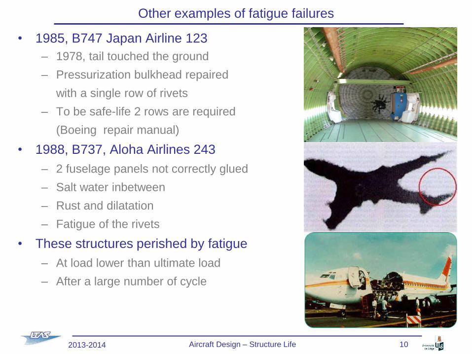
Other examples of fatigue failures
• 1985, B747 Japan Airline 123
– 1978, tail touched the ground
– Pressurization bulkhead repaired
with a single row of rivets
– To be safe-life 2 rows are required
(Boeing repair manual)
• 1988, B737, Aloha Airlines 243
– 2 fuselage panels not correctly glued
– Salt water inbetween
– Rust and dilatation
– Fatigue of the rivets
• These structures perished by fatigue
– At load lower than ultimate load
– After a large number of cycle
2013-2014 Aircraft Design – Structure Life 10
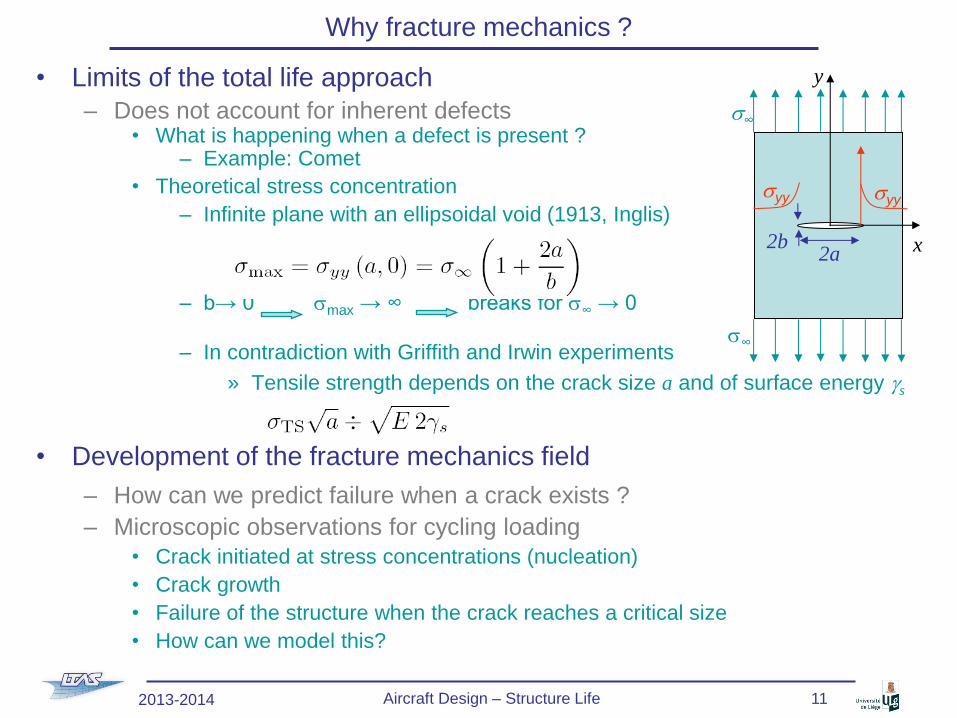
Why fracture mechanics ?
• Limits of the total life approach
– Does not account for inherent defects • What is happening when a defect is present ?
– Example: Comet
• Theoretical stress concentration
– Infinite plane with an ellipsoidal void (1913, Inglis)
– b→ 0 smax → ∞ breaks for s∞ → 0
– In contradiction with Griffith and Irwin experiments
» Tensile strength depends on the crack size a and of surface energy gs
• Development of the fracture mechanics field
– How can we predict failure when a crack exists ?
– Microscopic observations for cycling loading
• Crack initiated at stress concentrations (nucleation)
• Crack growth
• Failure of the structure when the crack reaches a critical size
• How can we model this?
2a 2b x
y
s∞
s∞
syy syy
2013-2014 Aircraft Design – Structure Life 11

Brittle / ductile fracture
• Mechanism of brittle failure
– (Almost) no plastic deformations prior to the (macroscopic) failure
– Cleavage: separation of crystallographic planes
• In general inside the grains
• Preferred directions: low bonding
• Between the grains: corrosion, H2, …
– Rupture criterion
• 1920, Griffith:
True e
Tru
e s
sTS
sp0
2013-2014 Aircraft Design – Structure Life 12
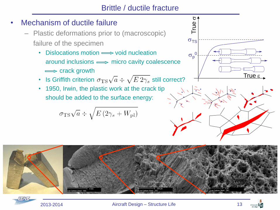
Brittle / ductile fracture
• Mechanism of ductile failure
– Plastic deformations prior to (macroscopic)
failure of the specimen
• Dislocations motion void nucleation
around inclusions micro cavity coalescence
crack growth
• Is Griffith criterion still correct?
• 1950, Irwin, the plastic work at the crack tip
should be added to the surface energy:
True e
Tru
e s
sTS
sp0
2013-2014 Aircraft Design – Structure Life 13
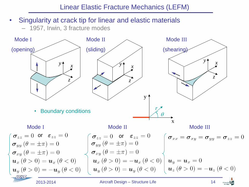
Linear Elastic Fracture Mechanics (LEFM)
• Singularity at crack tip for linear and elastic materials – 1957, Irwin, 3 fracture modes
• Boundary conditions
Mode I Mode II Mode III
(opening) (sliding) (shearing)
y
x
r q
Mode I Mode II Mode III
or or
y x
z
y x
z
y x
z
2013-2014 Aircraft Design – Structure Life 14

• Singularity at crack tip for linear and elastic materials (2)
– Asymptotic solutions (Airy functions, see fracture mechanics classes)
with for plane s & plane e
• Introduction of the Stress Intensity Factors - SIF (Pa m1/2)
• Ki are dependent on both the loading and the geometry
Linear Elastic Fracture Mechanics (LEFM)
y
x
r q
Mode I Mode II Mode III
2013-2014 Aircraft Design – Structure Life 15
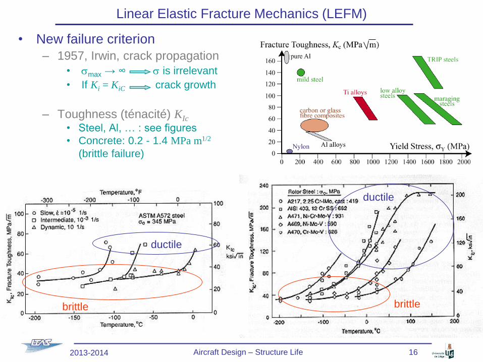
• New failure criterion
– 1957, Irwin, crack propagation
• smax → ∞ s is irrelevant
• If Ki = KiC crack growth
– Toughness (ténacité) KIc
• Steel, Al, … : see figures
• Concrete: 0.2 - 1.4 MPa m1/2
(brittle failure)
Linear Elastic Fracture Mechanics (LEFM)
brittle
ductile
brittle
ductile
2013-2014 Aircraft Design – Structure Life 16

• Stress Intensity Factor (SIF) – Computation of the SIFs Ki
• Analytical (crack 2a in an infinite plane)
• For other geometries or loadings
• bi obtained by
– Superposition
– FEM
– Energy approach
» Related to Griffith’s work
» See next slides
– For 2 loadings a & b: KI = KIa+ KI
b
– BUT for 2 modes K ≠ KI+KII
Linear Elastic Fracture Mechanics (LEFM)
s∞ s∞
y
2a
x
s∞
s∞
y
2a
x
t∞
t∞
y
2a
x
t∞
t∞
2013-2014 Aircraft Design – Structure Life 17
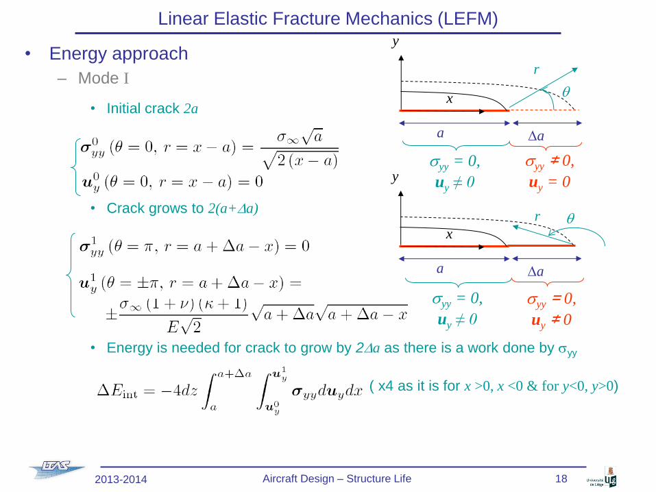
Linear Elastic Fracture Mechanics (LEFM)
• Energy approach
– Mode I
• Initial crack 2a
• Crack grows to 2(a+Da)
• Energy is needed for crack to grow by 2Da as there is a work done by syy
( x4 as it is for x >0, x <0 & for y<0, y>0)
y
x
a Da
r
q
syy = 0,
uy ≠ 0
syy ≠ 0,
uy = 0 y
x
a Da
r q
syy = 0,
uy ≠ 0
syy = 0,
uy ≠ 0
2013-2014 Aircraft Design – Structure Life 18
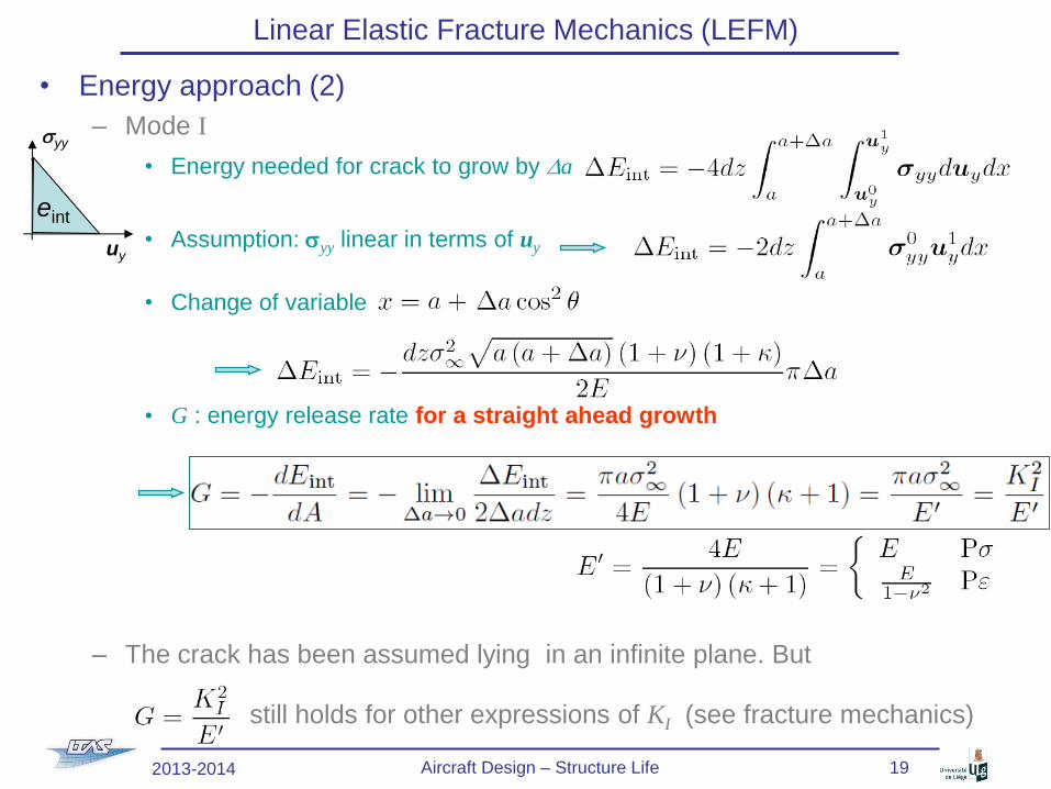
Linear Elastic Fracture Mechanics (LEFM)
• Energy approach (2)
– Mode I
• Energy needed for crack to grow by Da
• Assumption: syy linear in terms of uy
• Change of variable
• G : energy release rate for a straight ahead growth
– The crack has been assumed lying in an infinite plane. But
still holds for other expressions of KI (see fracture mechanics)
uy
syy
eint
2013-2014 Aircraft Design – Structure Life 19

Linear Elastic Fracture Mechanics (LEFM)
• Energy approach (3)
– 1920, Griffith, energy conservation:
• Total energy E is the sum of the internal (elastic) energy Eint with the energy
G needed to create surfaces A
• If gs is the surface energy (material property of brittle material)
crack growth if
– Mode I, infinite plane
• Strength
• Glass: Gc = 2 gs ~ 2 Jm-2, E = 60 GPa
• Steel: Gc = plast. dissipation ~ 200 kJm-2, E = 210 GPa
– Straight ahead propagation for general loading
• Proceeding as for mode I:
crack growth if
A crack creates 2
surfaces A
Depend on the
crack size
2013-2014 Aircraft Design – Structure Life 20

Brittle / ductile fracture
• Example: Liberty ships (WWII)
– Steel at low T°: brittle
• with gs ~ 3400 J m-2
– Steel at room T°: ductile
• with 2gs + Wpl ~ 200 kJ m-2
– Use of low-grade steel
• In cold weather:
DBTT ~ water temperature
• When put in water existing
cracks lead to failure
• 30% of the liberty ships
suffered from fracture
2013-2014 Aircraft Design – Structure Life 21

Linear Elastic Fracture Mechanics (LEFM)
• Energy approach: J-integral
– Energy release rate
• Straight ahead propagation for linear elasticity
– Should be related to the energy flowing toward the crack tip
• J-integral
– Defined even for non-linear materials
– Is path independent if the contour
G embeds a straight crack tip
– BUT no assumption on subsequent
growth direction
– If crack grows straight ahead G=J
– If linear elasticity
– Can be extended to plasticity if no unloading (see fracture mechanics)
• Advantages
– Efficient numerical computation of the SIFs
– Useful for non perfectly brittle materials
x
y B
G
a
D
r
q
2013-2014 Aircraft Design – Structure Life 22
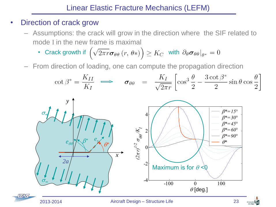
Linear Elastic Fracture Mechanics (LEFM)
• Direction of crack grow
– Assumptions: the crack will grow in the direction where the SIF related to
mode I in the new frame is maximal
• Crack growth if with
– From direction of loading, one can compute the propagation direction
2a x
y
s∞
s∞
b*
q* er
r eqq
2013-2014 Aircraft Design – Structure Life 23
-100 0 100-4
-2
0
2
4
q [°]
(2
r)1
/2 s
qq /
KI
b*=15°
b*=30°
b*=45°
b*=60°
b*=90°
q*
Maximum is for q <0
q [deg.]
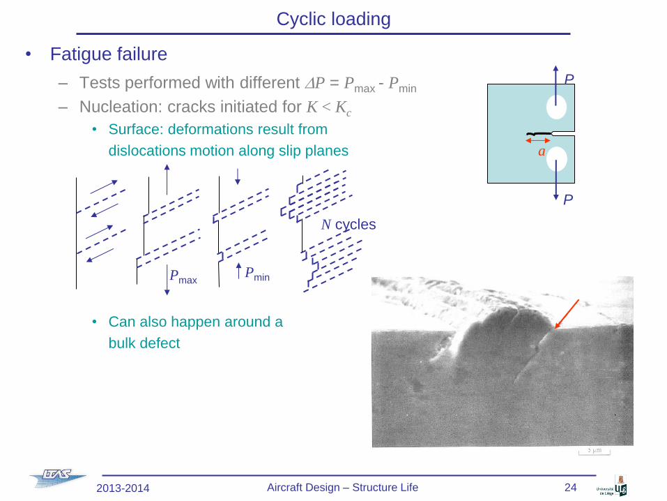
Cyclic loading
• Fatigue failure
– Tests performed with different DP = Pmax - Pmin
– Nucleation: cracks initiated for K < Kc
• Surface: deformations result from
dislocations motion along slip planes
• Can also happen around a
bulk defect
P
P
a
N cycles
Pmin Pmax
2013-2014 Aircraft Design – Structure Life 24
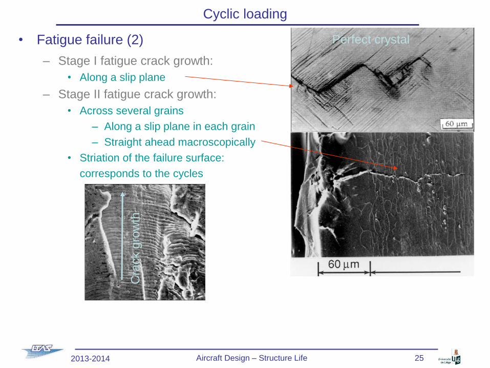
Cyclic loading
• Fatigue failure (2)
– Stage I fatigue crack growth:
• Along a slip plane
– Stage II fatigue crack growth:
• Across several grains
– Along a slip plane in each grain
– Straight ahead macroscopically
• Striation of the failure surface:
corresponds to the cycles
Perfect crystal
Cra
ck g
row
th
2013-2014 Aircraft Design – Structure Life 25

Cyclic loading
• Fatigue failure (3)
– SSY assumption
• Tests: conditioning parameters
– DP &
– Pmin / Pmax
• Therefore fatigue failure
can be described by
– DK = Kmax- Kmin &
– R = Kmin/Kmax
• There is DKth such that if DK ~ DKth:
– The crack has a growth rate lower than one atomic spacing per cycle
(statistical value)
– Dormant crack
Interval of striations
P
P
a
a (
cm)
Nf (105) 1 2 3 4 5 6 7
5
4
3
2
DP1
DP2 > DP1
Structure inspection
possible (for DP1) Rapid crack
growth
Rupture
2013-2014 Aircraft Design – Structure Life 26

Cyclic loading
• Crack growth rate
– Zone I
• Stage I fatigue crack growth
• DKth depends on R
– Zone II
• Stage II fatigue crack growth: striation
• 1963, Paris-Erdogan
– Depends on the geometry, the loading, the frequency
– Steel: DKth ~ 2-5 MPa m1/2 , C ~ 0.07-0.11 10-11 [m (MPa m1/2)-m], m ~ 4
– Steel in sea water: DKth ~ 1-1.5 MPa m1/2, C ~ 1.6 10-11 [idem], m ~ 3.3
• Be careful: K depends on a integration required to get a(Nf)
– Mode I :
– Zone III
• Rapid crack growth until failure
• Static behavior (cleavage) due to the effect of Kmax(a)
• There is failure once af is reached, with af such that Kmax(af) = Kc
da
/ d
Nf
logDK DKth
Zone I Zone II Zone III
R
1
m
2013-2014 Aircraft Design – Structure Life 27
Fatigue design
• « Infinite life design »
– sa < se: « infinite » life
– Economically deficient
• « Safe life design »
– No crack before a determined number of cycles
• At the end of the expected life the component
is changed even if no failure has occurred
• Emphasis on prevention of crack initiation
• Approach theoretical in nature
– Assumes initial crack free structures
– Use of sa – Nf curves (stress life)
• Add factor of safety
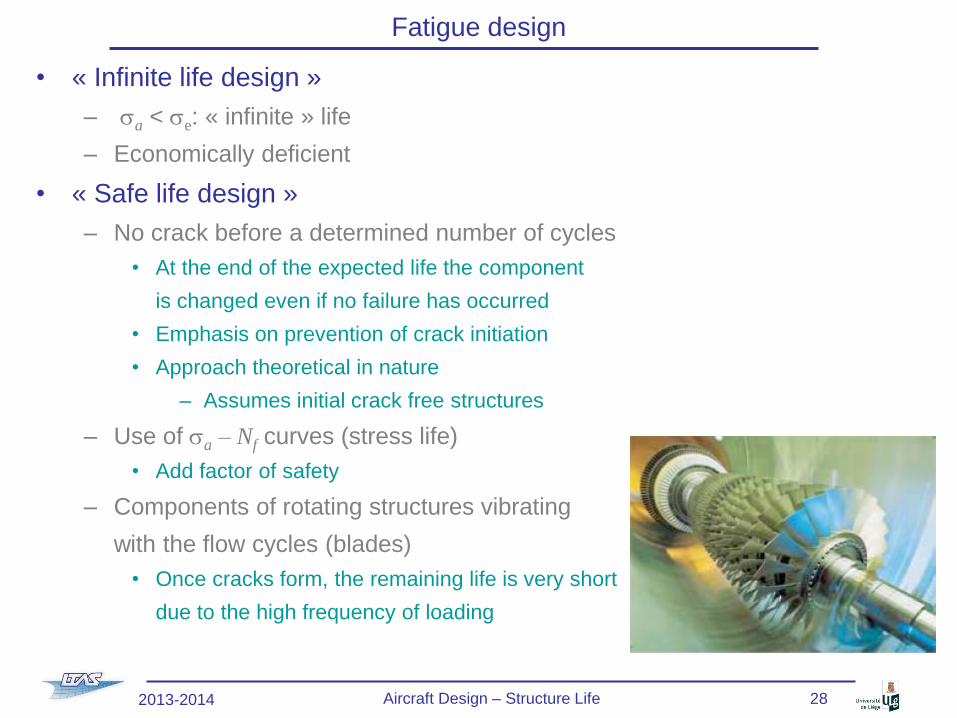
– Components of rotating structures vibrating
with the flow cycles (blades)
• Once cracks form, the remaining life is very short
due to the high frequency of loading
2013-2014 Aircraft Design – Structure Life 28
Fatigue design
• « Fail safe design »
– Even if an individual member of a component fails, there should be sufficient structural integrity to operate safely
– Load paths and crack arresters
– Mandate periodic inspection
– Accent on crack growth rather than crack initiation
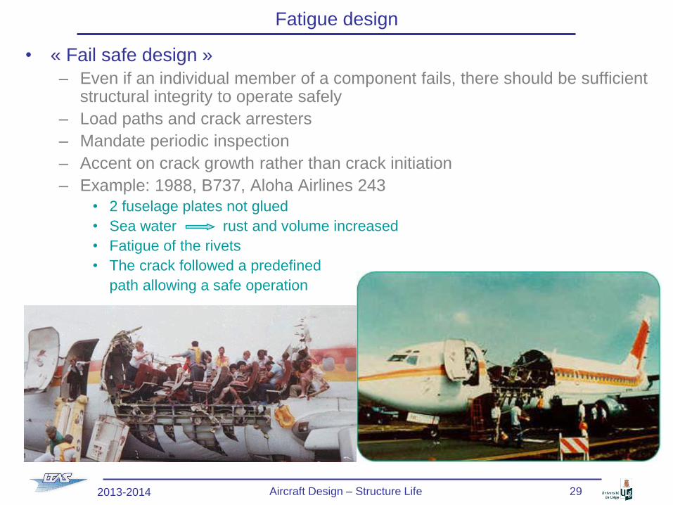
– Example: 1988, B737, Aloha Airlines 243
• 2 fuselage plates not glued
• Sea water rust and volume increased
• Fatigue of the rivets
• The crack followed a predefined
path allowing a safe operation
2013-2014 Aircraft Design – Structure Life 29

Fatigue design
• « Damage tolerant design »
– Assume cracks are present from the beginning of service
– Characterize the significance of fatigue cracks on structural performance
• Control initial crack sizes through
manufacturing processes and
(non-destructive) inspections
• Estimate crack growth rates during
service (Paris-Erdogan) & plan
conservative inspection intervals
(e.g. every so many years, number
of flights)
• Verify crack growth during
these inspections
• Predict end of life (af)
• Remove old structures from service
before predicted end-of-life (fracture) or
implement repair-rehabilitation strategy
– Non-destructive inspections
• Optical
• X-rays
• Ultrasonic (reflection on crack surface)
2013-2014 Aircraft Design – Structure Life 30

References
• Lecture notes
– Lecture Notes on Fracture Mechanics, Alan T. Zehnder, Cornell University,
Ithaca,
– Other references
– « on-line »
• Fracture Mechanics, Piet Schreurs, TUe,
http://www.mate.tue.nl/~piet/edu/frm/sht/bmsht.html
– Book
• Fracture Mechanics: Fundamentals and applications, D. T. Anderson. CRC press,
1991.
2013-2014 Aircraft Design – Structure Life 31