aircraft engine
TRANSCRIPT
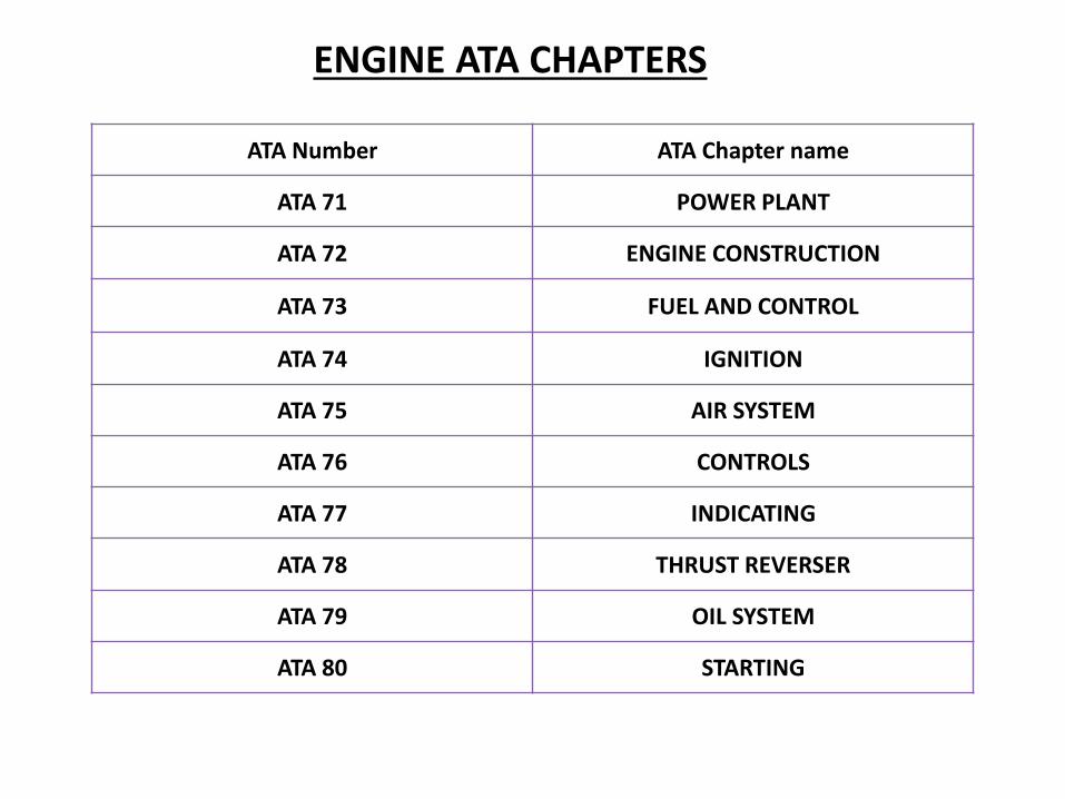
ATA Number ATA Chapter name
ATA 71 POWER PLANT
ATA 72 ENGINE CONSTRUCTION
ATA 73 FUEL AND CONTROL
ATA 74 IGNITION
ATA 75 AIR SYSTEM
ATA 76 CONTROLS
ATA 77 INDICATING
ATA 78 THRUST REVERSER
ATA 79 OIL SYSTEM
ATA 80 STARTING
ENGINE ATA CHAPTERS
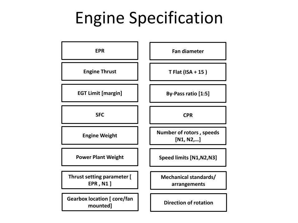
Engine Specification
EPR
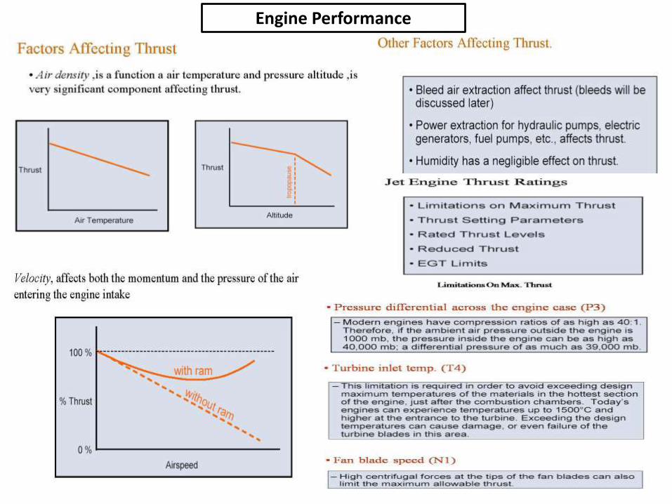
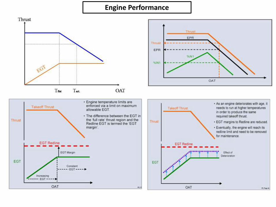
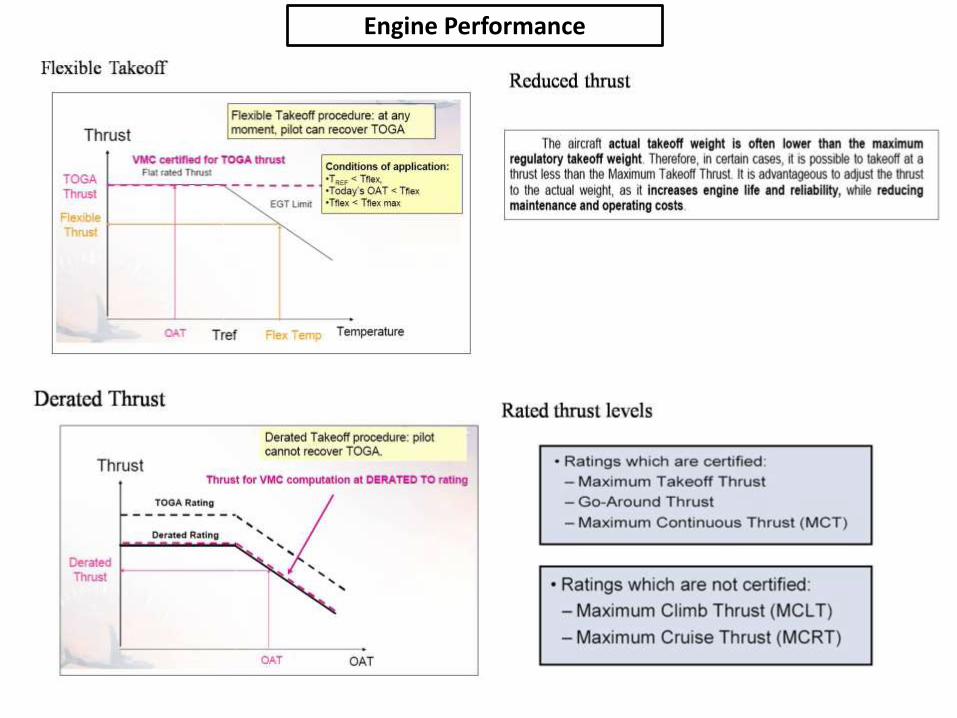
Engine Thrust
EGT Limit [margin]
SFC
Engine Weight
Power Plant Weight
Fan diameter
T Flat (ISA + 15 )
By-Pass ratio [1:5]
CPR
Number of rotors , speeds [N1, N2,…]
Speed limits [N1,N2,N3]
Thrust setting parameter [ EPR , N1 ]
Mechanical standards/ arrangements
Gearbox location [ core/fan mounted]
Direction of rotation
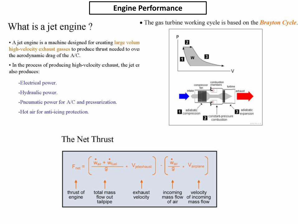
Engine Performance
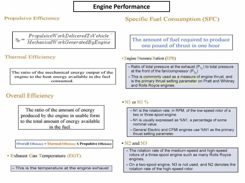
Engine Performance
Engine Performance
Engine Performance
Engine Performance
Engine Performance

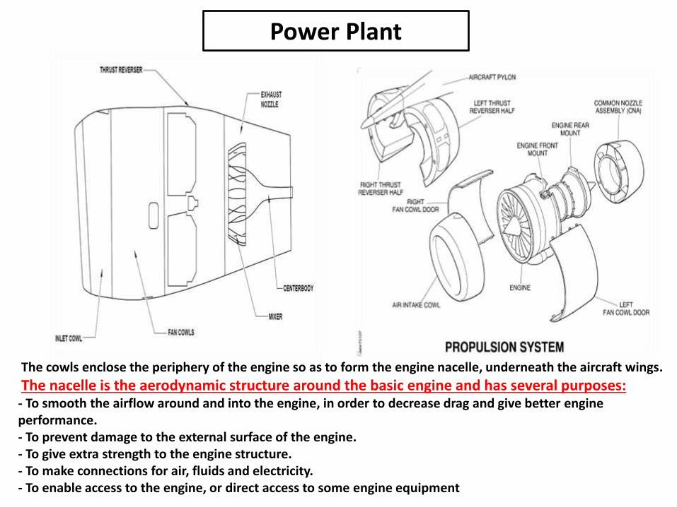
The cowls enclose the periphery of the engine so as to form the engine nacelle, underneath the aircraft wings.
The nacelle is the aerodynamic structure around the basic engine and has several purposes: - To smooth the airflow around and into the engine, in order to decrease drag and give better engine performance. - To prevent damage to the external surface of the engine. - To give extra strength to the engine structure. - To make connections for air, fluids and electricity. - To enable access to the engine, or direct access to some engine equipment
Power Plant
Air Inlet Cowl
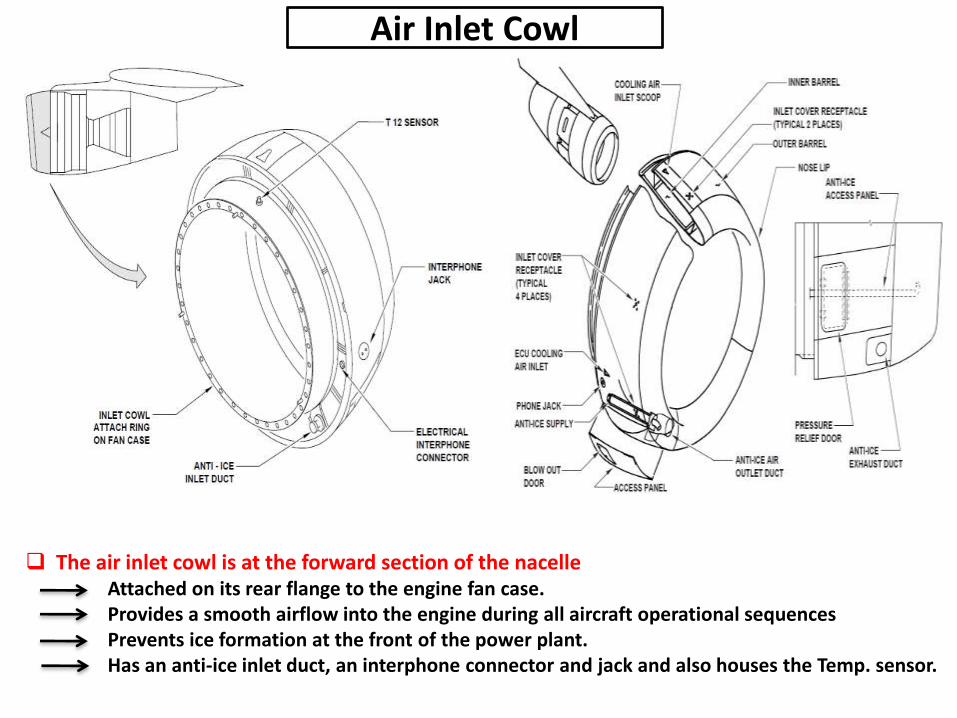
The air inlet cowl is at the forward section of the nacelle Attached on its rear flange to the engine fan case.Provides a smooth airflow into the engine during all aircraft operational sequences Prevents ice formation at the front of the power plant.Has an anti-ice inlet duct, an interphone connector and jack and also houses the Temp. sensor.
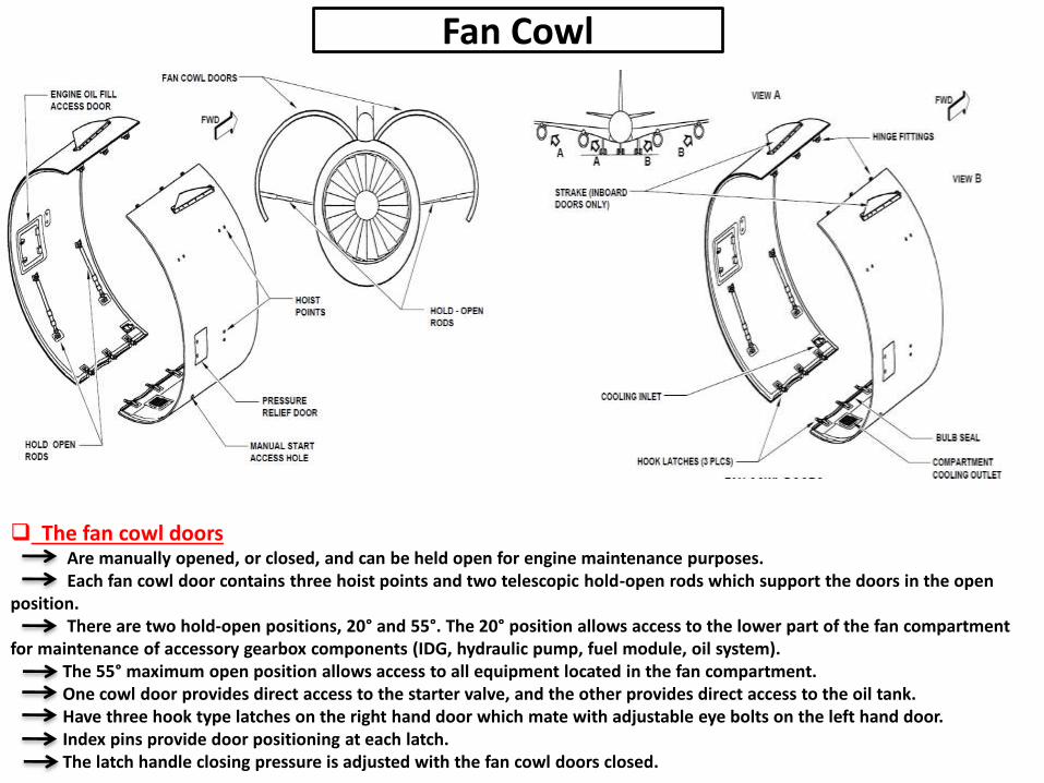
The fan cowl doorsAre manually opened, or closed, and can be held open for engine maintenance purposes.Each fan cowl door contains three hoist points and two telescopic hold-open rods which support the doors in the open
position.There are two hold-open positions, 20° and 55°. The 20° position allows access to the lower part of the fan compartment
for maintenance of accessory gearbox components (IDG, hydraulic pump, fuel module, oil system).The 55° maximum open position allows access to all equipment located in the fan compartment.One cowl door provides direct access to the starter valve, and the other provides direct access to the oil tank. Have three hook type latches on the right hand door which mate with adjustable eye bolts on the left hand door.Index pins provide door positioning at each latch.The latch handle closing pressure is adjusted with the fan cowl doors closed.
Fan Cowl
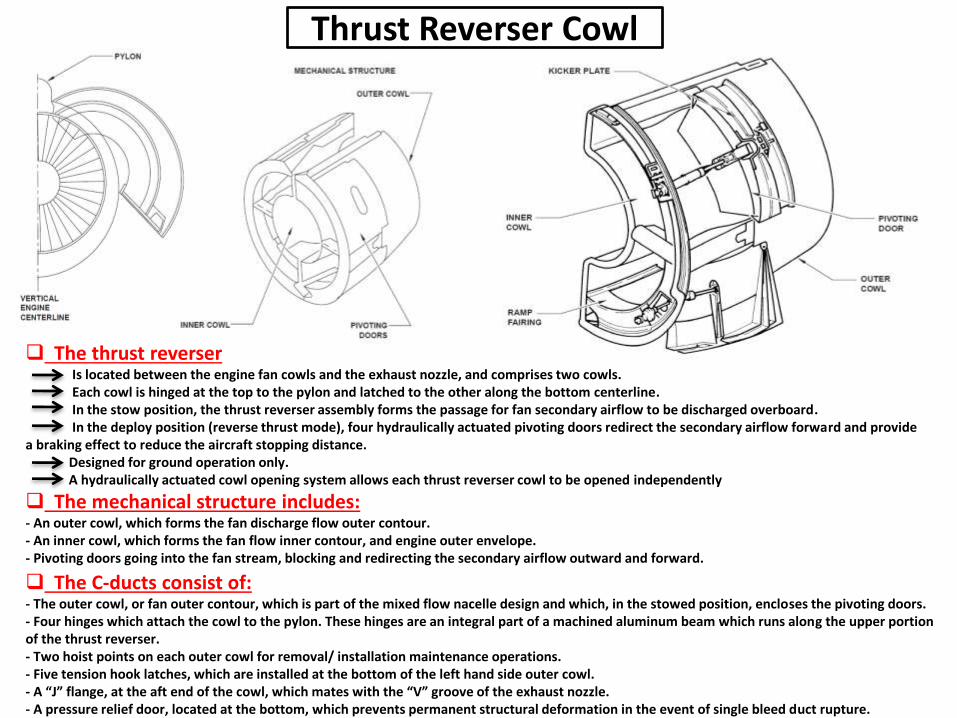
The thrust reverserIs located between the engine fan cowls and the exhaust nozzle, and comprises two cowls. Each cowl is hinged at the top to the pylon and latched to the other along the bottom centerline.In the stow position, the thrust reverser assembly forms the passage for fan secondary airflow to be discharged overboard.In the deploy position (reverse thrust mode), four hydraulically actuated pivoting doors redirect the secondary airflow forward and provide
a braking effect to reduce the aircraft stopping distance. Designed for ground operation only.A hydraulically actuated cowl opening system allows each thrust reverser cowl to be opened independently
The mechanical structure includes: - An outer cowl, which forms the fan discharge flow outer contour. - An inner cowl, which forms the fan flow inner contour, and engine outer envelope. - Pivoting doors going into the fan stream, blocking and redirecting the secondary airflow outward and forward.
The C-ducts consist of: - The outer cowl, or fan outer contour, which is part of the mixed flow nacelle design and which, in the stowed position, encloses the pivoting doors. - Four hinges which attach the cowl to the pylon. These hinges are an integral part of a machined aluminum beam which runs along the upper portion of the thrust reverser. - Two hoist points on each outer cowl for removal/ installation maintenance operations. - Five tension hook latches, which are installed at the bottom of the left hand side outer cowl. - A “J” flange, at the aft end of the cowl, which mates with the “V” groove of the exhaust nozzle. - A pressure relief door, located at the bottom, which prevents permanent structural deformation in the event of single bleed duct rupture.
Thrust Reverser Cowl
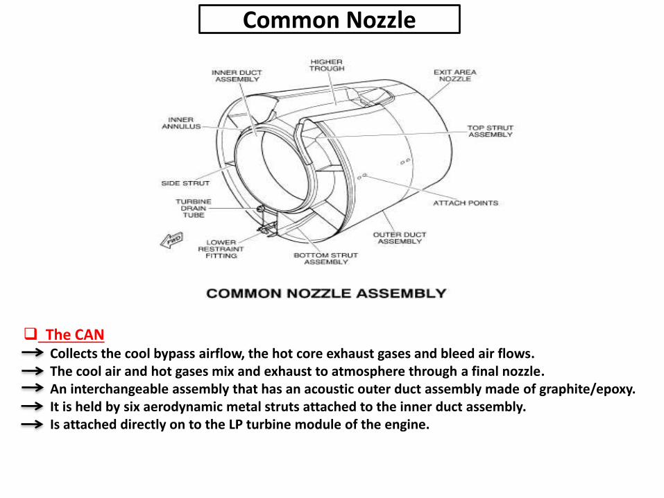
The CANCollects the cool bypass airflow, the hot core exhaust gases and bleed air flows.The cool air and hot gases mix and exhaust to atmosphere through a final nozzle.An interchangeable assembly that has an acoustic outer duct assembly made of graphite/epoxy.It is held by six aerodynamic metal struts attached to the inner duct assembly.Is attached directly on to the LP turbine module of the engine.
Common Nozzle

Engine MountsFront Mounts
The engine mounts support the weight of the engine and transmit loads to the aircraft structure through the pylon.
The front mount Attached at the top of the intermediate case. The engine front mount transmits engine thrust, side and vertical loads to the aircraft pylon.The thrust and side loads are transmitted from the intermediate case through a split spherical bearing – which is mounted on
the intermediate case - to the cylindrical trunnion.These loads are now transmitted through the main attachment bracket to the aircraft pylon.The vertical loads are transmitted from the intermediate case through the vertical load links to the vertical load support beam.They are then transmitted through the front horizontal trunnion to the main attachment bracket to the aircraft pylon.The main attachment bracket is in two halves to give more than one route for the thrust and side loads.If there is a failure of a primary component that affects the vertical loading the engine would drop and the fail safe catcher
link would contact the rear trunnion (on the main attachment bracket) and support the vertical loads.
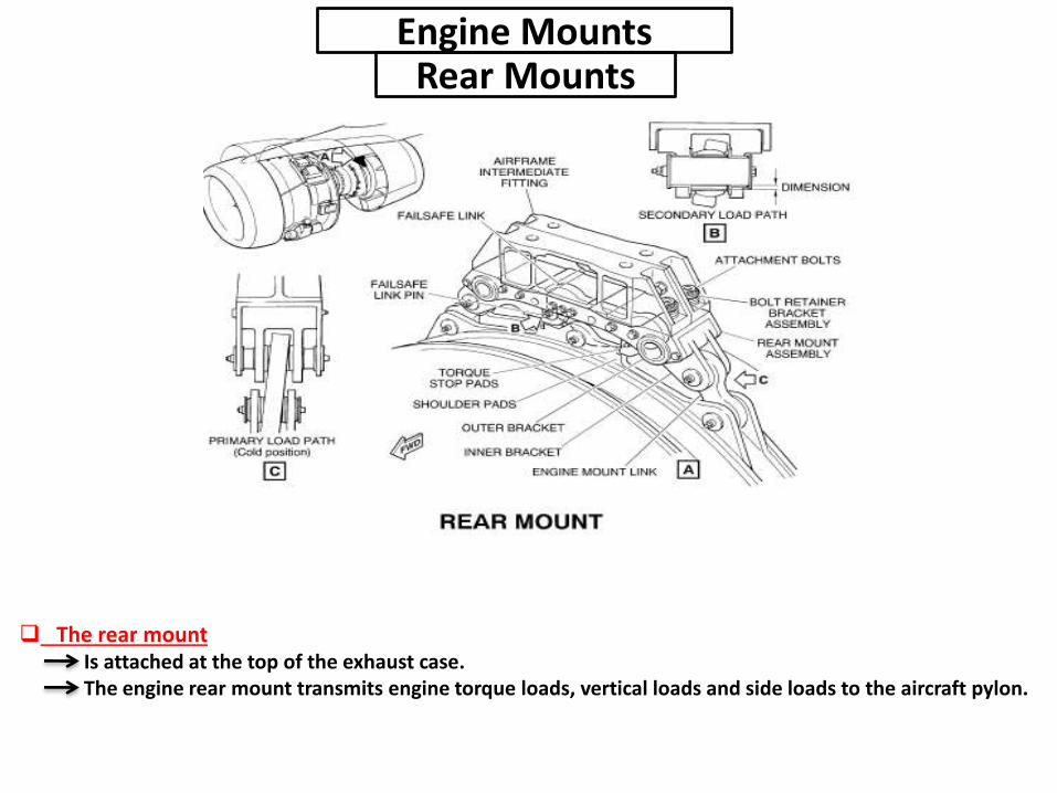
Engine MountsRear Mounts
The rear mountIs attached at the top of the exhaust case.The engine rear mount transmits engine torque loads, vertical loads and side loads to the aircraft pylon.
Engine ConstructionAir Intake
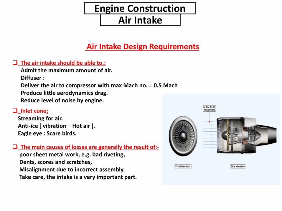
Air Intake Design Requirements
The air intake should be able to.:Admit the maximum amount of air.Diffuser :Deliver the air to compressor with max Mach no. = 0.5 MachProduce little aerodynamics drag.Reduce level of noise by engine.
The main causes of losses are generally the result of:-poor sheet metal work, e.g. bad riveting,Dents, scores and scratches,Misalignment due to incorrect assembly.Take care, the intake is a very important part.
Inlet cone:Streaming for air.Anti-ice [ vibration – Hot air ].Eagle eye : Scare birds.
Engine ConstructionCompressor
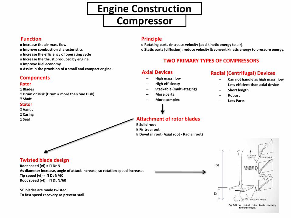
Functiono Increase the air mass flowo Improve combustion characteristicso Increase the efficiency of operating cycleo Increase the thrust produced by engineo Improve fuel economyo Assist in the provision of a small and compact engine.
Principleo Rotating parts :Increase velocity [add kinetic energy to air].o Static parts [diffusion]: reduce velocity & convert kinetic energy to pressure energy.
ComponentsRotor
BladesDrum or Disk (Drum = more than one Disk)Shaft
StatorVanesCasingSeal Attachment of rotor blades
Solid rootFir tree rootDovetail root (Axial root - Radial root)
Radial (Centrifugal) Devices– Can not handle as high mass flow
– Less efficient than axial device
– Short length
– Robust
– Less Parts
Axial Devices– High mass flow
– High efficiency
– Stackable (multi-staging)
– More parts
– More complex
TWO PRIMARY TYPES OF COMPRESSORS
Twisted blade designRoot speed (vf) = Π Dr NAs diameter increase, angle of attack increase, so rotation speed increase.Tip speed (vf) = Π Dt N/60Root speed (vf) = Π Dt N/60
SO blades are made twisted,To fast speed recovery so prevent stall
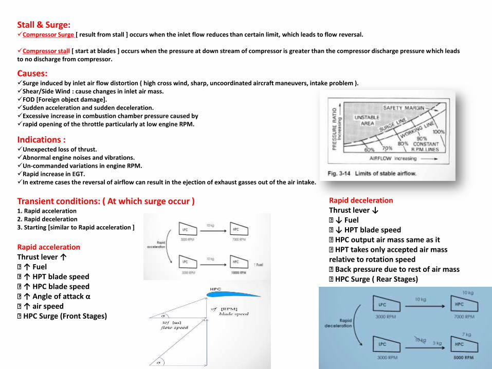
Stall & Surge:Compressor Surge [ result from stall ] occurs when the inlet flow reduces than certain limit, which leads to flow reversal.
Compressor stall [ start at blades ] occurs when the pressure at down stream of compressor is greater than the compressor discharge pressure which leads to no discharge from compressor.
Causes:Surge induced by inlet air flow distortion ( high cross wind, sharp, uncoordinated aircraft maneuvers, intake problem ).Shear/Side Wind : cause changes in inlet air mass.FOD [Foreign object damage].Sudden acceleration and sudden deceleration.Excessive increase in combustion chamber pressure caused byrapid opening of the throttle particularly at low engine RPM.
Indications :Unexpected loss of thrust.Abnormal engine noises and vibrations.Un-commanded variations in engine RPM.Rapid increase in EGT.In extreme cases the reversal of airflow can result in the ejection of exhaust gasses out of the air intake.
Transient conditions: ( At which surge occur )1. Rapid acceleration2. Rapid deceleration3. Starting [similar to Rapid acceleration ]
Rapid accelerationThrust lever ↑
↑ Fuel↑ HPT blade speed↑ HPC blade speed↑ Angle of attack α↑ air speedHPC Surge (Front Stages)
Rapid decelerationThrust lever ↓
↓ Fuel↓ HPT blade speedHPC output air mass same as itHPT takes only accepted air mass
relative to rotation speedBack pressure due to rest of air massHPC Surge ( Rear Stages)
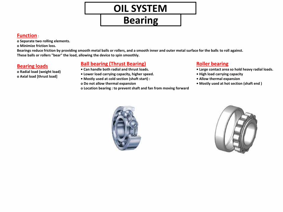
Function :
o Separate two rolling elements.o Minimize friction loss.Bearings reduce friction by providing smooth metal balls or rollers, and a smooth inner and outer metal surface for the balls to roll against. These balls or rollers "bear" the load, allowing the device to spin smoothly.
Bearing loadso Radial load (weight load)o Axial load [thrust load]
Roller bearing• Large contact area so hold heavy radial loads.• High load carrying capacity• Allow thermal expansion• Mostly used at hot section (shaft end )
Ball bearing (Thrust Bearing)• Can handle both radial and thrust loads.• Lower load carrying capacity, higher speed.• Mostly used at cold section (shaft start) :o Do not allow thermal expansiono Location bearing : to prevent shaft and fan from moving forward
OIL SYSTEMBearing
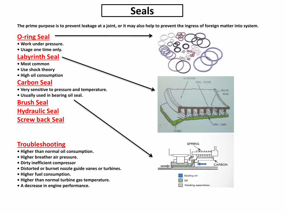
SealsThe prime purpose is to prevent leakage at a joint, or it may also help to prevent the ingress of foreign matter into system.
O-ring Seal• Work under pressure.• Usage one time only.
Labyrinth Seal• Most common• Use shock theory• High oil consumption
Carbon Seal• Very sensitive to pressure and temperature.• Usually used in bearing oil seal.
Brush SealHydraulic SealScrew back Seal
Troubleshooting• Higher than normal oil consumption.• Higher breather air pressure.• Dirty inefficient compressor• Distorted or burnet nozzle guide vanes or turbines.• Higher fuel consumption.• Higher than normal turbine gas temperature.• A decrease in engine performance.
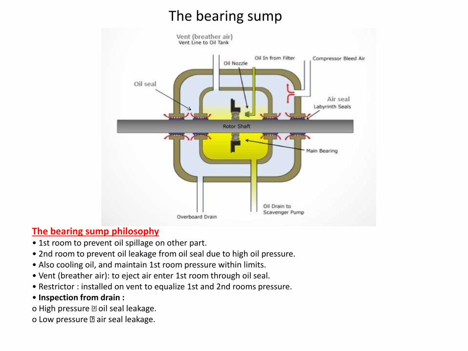
The bearing sump philosophy• 1st room to prevent oil spillage on other part.• 2nd room to prevent oil leakage from oil seal due to high oil pressure.• Also cooling oil, and maintain 1st room pressure within limits.• Vent (breather air): to eject air enter 1st room through oil seal.• Restrictor : installed on vent to equalize 1st and 2nd rooms pressure.• Inspection from drain :o High pressure oil seal leakage.o Low pressure air seal leakage.
The bearing sump
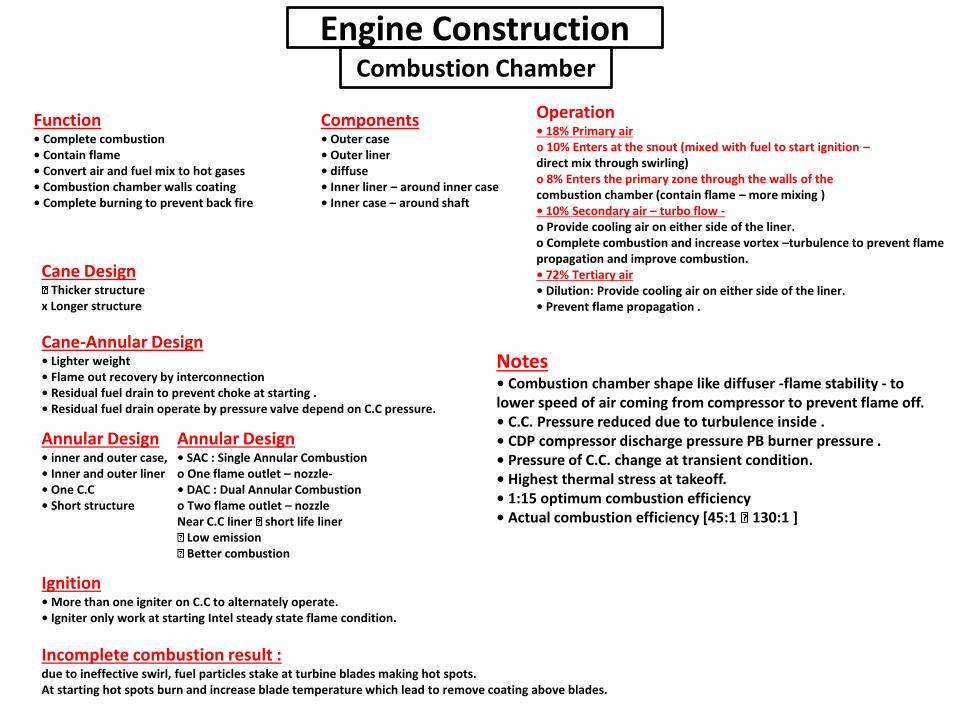
Engine ConstructionCombustion Chamber
Function• Complete combustion• Contain flame• Convert air and fuel mix to hot gases• Combustion chamber walls coating• Complete burning to prevent back fire
Components• Outer case• Outer liner• diffuse• Inner liner – around inner case• Inner case – around shaft
Operation• 18% Primary airo 10% Enters at the snout (mixed with fuel to start ignition –direct mix through swirling)o 8% Enters the primary zone through the walls of thecombustion chamber (contain flame – more mixing )• 10% Secondary air – turbo flow -o Provide cooling air on either side of the liner.o Complete combustion and increase vortex –turbulence to prevent flame propagation and improve combustion.• 72% Tertiary air• Dilution: Provide cooling air on either side of the liner.• Prevent flame propagation .
Cane-Annular Design• Lighter weight• Flame out recovery by interconnection• Residual fuel drain to prevent choke at starting .• Residual fuel drain operate by pressure valve depend on C.C pressure.
Cane DesignThicker structure
x Longer structure
Annular Design• inner and outer case,• Inner and outer liner• One C.C• Short structure
Annular Design• SAC : Single Annular Combustiono One flame outlet – nozzle-• DAC : Dual Annular Combustiono Two flame outlet – nozzleNear C.C liner short life liner
Low emissionBetter combustion
Ignition• More than one igniter on C.C to alternately operate.• Igniter only work at starting Intel steady state flame condition.
Incomplete combustion result :due to ineffective swirl, fuel particles stake at turbine blades making hot spots.At starting hot spots burn and increase blade temperature which lead to remove coating above blades.
Notes• Combustion chamber shape like diffuser -flame stability - to lower speed of air coming from compressor to prevent flame off.• C.C. Pressure reduced due to turbulence inside .• CDP compressor discharge pressure PB burner pressure .• Pressure of C.C. change at transient condition.• Highest thermal stress at takeoff.• 1:15 optimum combustion efficiency• Actual combustion efficiency [45:1 130:1 ]
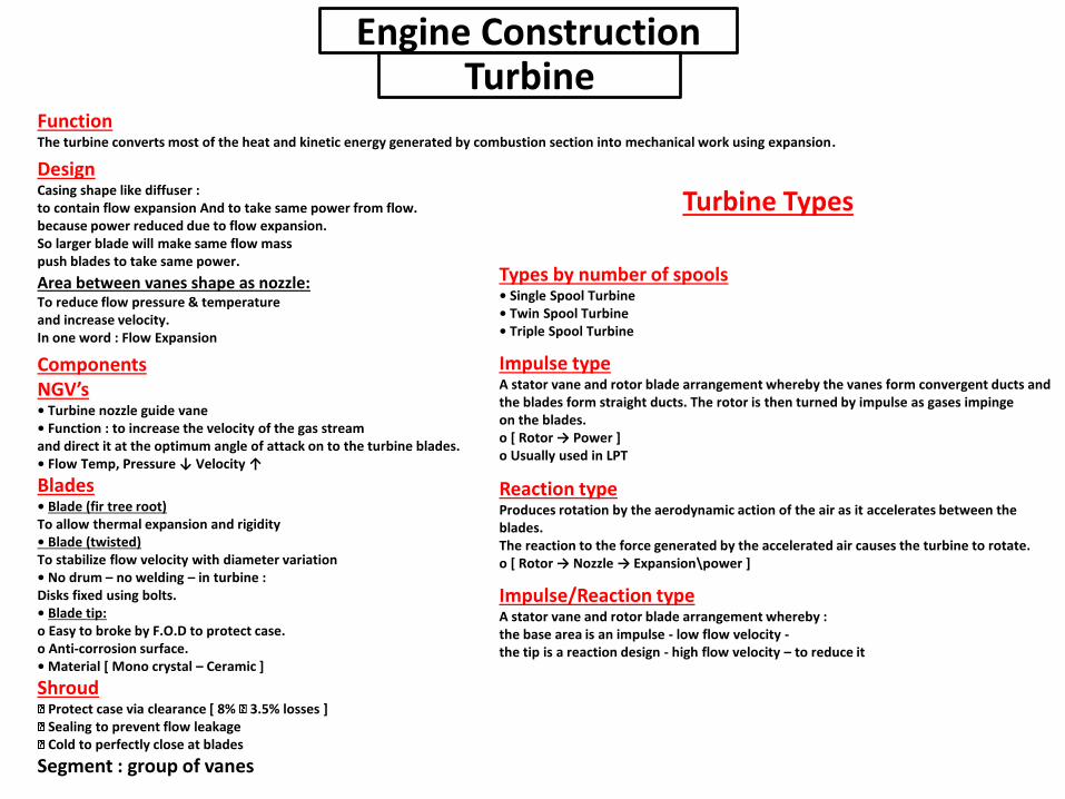
Engine ConstructionTurbine
FunctionThe turbine converts most of the heat and kinetic energy generated by combustion section into mechanical work using expansion.
Types by number of spools• Single Spool Turbine• Twin Spool Turbine• Triple Spool Turbine
DesignCasing shape like diffuser :to contain flow expansion And to take same power from flow.because power reduced due to flow expansion.So larger blade will make same flow masspush blades to take same power.
Area between vanes shape as nozzle:To reduce flow pressure & temperatureand increase velocity.In one word : Flow Expansion
ComponentsNGV’s• Turbine nozzle guide vane• Function : to increase the velocity of the gas streamand direct it at the optimum angle of attack on to the turbine blades.• Flow Temp, Pressure ↓ Velocity ↑
Blades• Blade (fir tree root)To allow thermal expansion and rigidity• Blade (twisted)To stabilize flow velocity with diameter variation• No drum – no welding – in turbine :Disks fixed using bolts.• Blade tip:o Easy to broke by F.O.D to protect case.o Anti-corrosion surface.• Material [ Mono crystal – Ceramic ]
ShroudProtect case via clearance [ 8% 3.5% losses ]Sealing to prevent flow leakageCold to perfectly close at blades
Segment : group of vanes
Impulse typeA stator vane and rotor blade arrangement whereby the vanes form convergent ducts and the blades form straight ducts. The rotor is then turned by impulse as gases impingeon the blades.o [ Rotor → Power ]o Usually used in LPT
Reaction typeProduces rotation by the aerodynamic action of the air as it accelerates between the blades.The reaction to the force generated by the accelerated air causes the turbine to rotate.o [ Rotor → Nozzle → Expansion\power ]
Impulse/Reaction typeA stator vane and rotor blade arrangement whereby :the base area is an impulse - low flow velocity -the tip is a reaction design - high flow velocity – to reduce it
Turbine Types
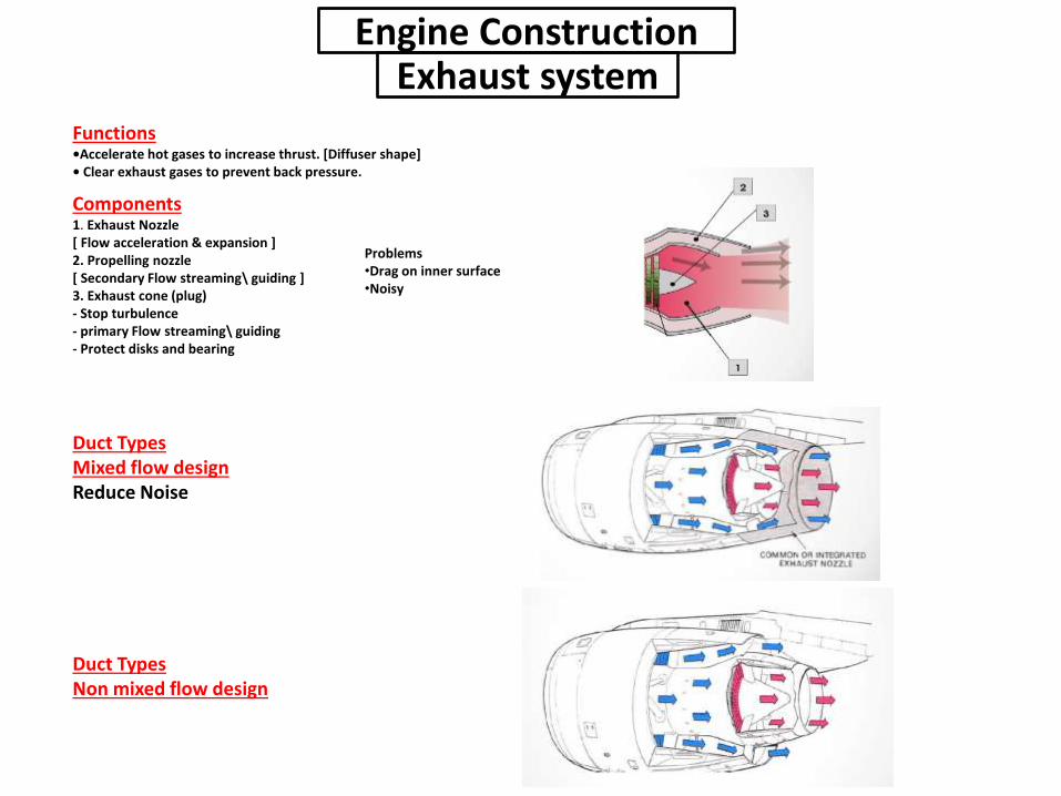
Engine ConstructionExhaust system
Functions•Accelerate hot gases to increase thrust. [Diffuser shape]• Clear exhaust gases to prevent back pressure.
Components1. Exhaust Nozzle[ Flow acceleration & expansion ]2. Propelling nozzle[ Secondary Flow streaming\ guiding ]3. Exhaust cone (plug)- Stop turbulence- primary Flow streaming\ guiding- Protect disks and bearing
Duct TypesMixed flow designReduce Noise
Duct TypesNon mixed flow design
Problems•Drag on inner surface•Noisy

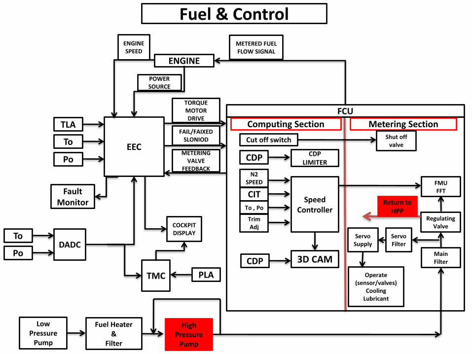
Fuel & Control
EEC
DADC
TMC
COCKPIT DISPLAY
ENGINE
TLA
To
Po
POWER SOURCE
To
Po
PLA
METERED FUEL FLOW SIGNAL
TORQUE MOTOR DRIVE
FAIL/FAIXED SLONIOD
METERING VALVE
FEEDBACK
ENGINE SPEED
FCU
Computing Section Metering Section
CDP LIMITER
Speed Controller
3D CAMMain Filter
Regulating Valve
FMUFFT
Shut off valve
CDP
CDP
N2 SPEED
CIT
To , Po
Trim Adj
Cut off switch
Servo Filter
Servo Supply
Operate(sensor/valves)
CoolingLubricant
Low Pressure
Pump
Fuel Heater &
Filter
High Pressure
Pump
Return to HPP
Fault Monitor
Fuel & Control
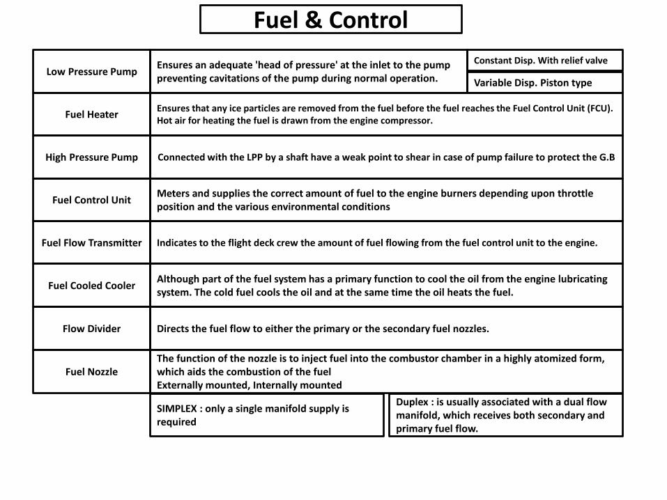
Low Pressure Pump
Fuel Heater
High Pressure Pump
Fuel Control Unit
Fuel Flow Transmitter
Fuel Cooled Cooler
Flow Divider
Fuel Nozzle
Ensures an adequate 'head of pressure' at the inlet to the pumppreventing cavitations of the pump during normal operation.
Ensures that any ice particles are removed from the fuel before the fuel reaches the Fuel Control Unit (FCU).Hot air for heating the fuel is drawn from the engine compressor.
Connected with the LPP by a shaft have a weak point to shear in case of pump failure to protect the G.B
Meters and supplies the correct amount of fuel to the engine burners depending upon throttle position and the various environmental conditions
Indicates to the flight deck crew the amount of fuel flowing from the fuel control unit to the engine.
Although part of the fuel system has a primary function to cool the oil from the engine lubricating system. The cold fuel cools the oil and at the same time the oil heats the fuel.
Directs the fuel flow to either the primary or the secondary fuel nozzles.
The function of the nozzle is to inject fuel into the combustor chamber in a highly atomized form, which aids the combustion of the fuel Externally mounted, Internally mounted
Variable Disp. Piston type
Constant Disp. With relief valve
SIMPLEX : only a single manifold supply is required
Duplex : is usually associated with a dual flow manifold, which receives both secondary and primary fuel flow.
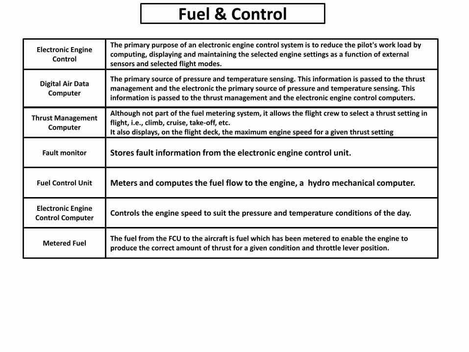
Thrust Management Computer
Fault monitor
Fuel Control Unit
Electronic Engine Control Computer
Metered Fuel
Although not part of the fuel metering system, it allows the flight crew to select a thrust setting in flight, i.e., climb, cruise, take-off, etc.It also displays, on the flight deck, the maximum engine speed for a given thrust setting
Stores fault information from the electronic engine control unit.
Meters and computes the fuel flow to the engine, a hydro mechanical computer.
Controls the engine speed to suit the pressure and temperature conditions of the day.
The fuel from the FCU to the aircraft is fuel which has been metered to enable the engine to produce the correct amount of thrust for a given condition and throttle lever position.
Fuel & Control
Electronic Engine Control
Digital Air Data Computer
The primary purpose of an electronic engine control system is to reduce the pilot's work load by computing, displaying and maintaining the selected engine settings as a function of external sensors and selected flight modes.
The primary source of pressure and temperature sensing. This information is passed to the thrust management and the electronic the primary source of pressure and temperature sensing. This information is passed to the thrust management and the electronic engine control computers.

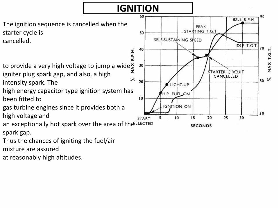
IGNITION
The ignition sequence is cancelled when the starter cycle iscancelled.
to provide a very high voltage to jump a wideigniter plug spark gap, and also, a high intensity spark. Thehigh energy capacitor type ignition system has been fitted togas turbine engines since it provides both a high voltage andan exceptionally hot spark over the area of the spark gap.Thus the chances of igniting the fuel/air mixture are assuredat reasonably high altitudes.
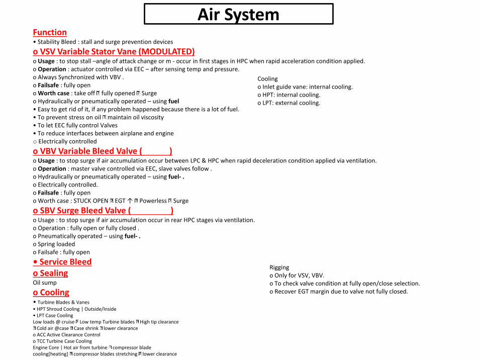
Function• Stability Bleed : stall and surge prevention devices
o VSV Variable Stator Vane (MODULATED)o Usage : to stop stall –angle of attack change or m - occur in first stages in HPC when rapid acceleration condition applied.o Operation : actuator controlled via EEC – after sensing temp and pressure.o Always Synchronized with VBV .o Failsafe : fully openo Worth case : take off fully opened Surgeo Hydraulically or pneumatically operated – using fuel • Easy to get rid of it, if any problem happened because there is a lot of fuel.• To prevent stress on oil maintain oil viscosity• To let EEC fully control Valves• To reduce interfaces between airplane and engineo Electrically controlled
o VBV Variable Bleed Valve ( )o Usage : to stop surge if air accumulation occur between LPC & HPC when rapid deceleration condition applied via ventilation.o Operation : master valve controlled via EEC, slave valves follow .o Hydraulically or pneumatically operated – using fuel- .o Electrically controlled.o Failsafe : fully openo Worth case : STUCK OPEN EGT ↑ Powerless Surge
o SBV Surge Bleed Valve ( )o Usage : to stop surge if air accumulation occur in rear HPC stages via ventilation.o Operation : fully open or fully closed .o Pneumatically operated – using fuel- .o Spring loadedo Failsafe : fully open
• Service Bleedo SealingOil sump
o Cooling• Turbine Blades & Vanes
• HPT Shroud Cooling | Outside/Inside• LPT Case CoolingLow loads @ cruise Low temp Turbine blades High tip clearance
Cold air @case Case shrink lower clearanceo ACC Active Clearance Controlo TCC Turbine Case CoolingEngine Core | Hot air from turbine compressor bladecooling[heating] compressor blades stretching lower clearance
Riggingo Only for VSV, VBV.o To check valve condition at fully open/close selection.o Recover EGT margin due to valve not fully closed.
Air System
Coolingo Inlet guide vane: internal cooling.o HPT: internal cooling.o LPT: external cooling.
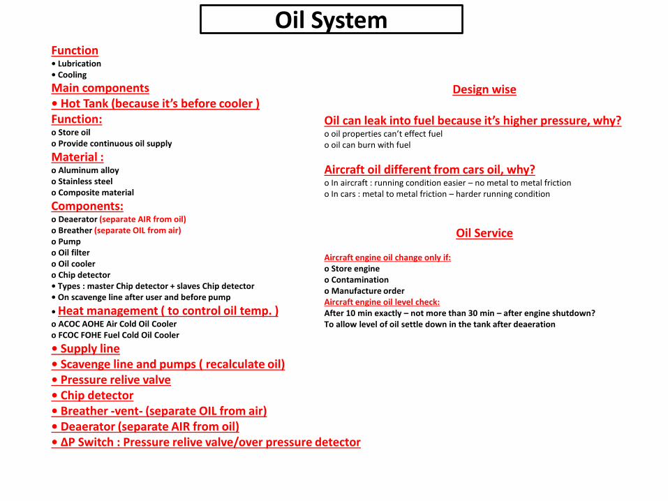
Function• Lubrication• Cooling
Oil System
Main components• Hot Tank (because it’s before cooler )Function:o Store oilo Provide continuous oil supply
Material :o Aluminum alloyo Stainless steelo Composite material
Components:o Deaerator (separate AIR from oil)o Breather (separate OIL from air)o Pumpo Oil filtero Oil coolero Chip detector• Types : master Chip detector + slaves Chip detector• On scavenge line after user and before pump
• Heat management ( to control oil temp. )o ACOC AOHE Air Cold Oil Coolero FCOC FOHE Fuel Cold Oil Cooler
• Supply line• Scavenge line and pumps ( recalculate oil)• Pressure relive valve• Chip detector• Breather -vent- (separate OIL from air)• Deaerator (separate AIR from oil)• ΔP Switch : Pressure relive valve/over pressure detector
Design wise
Oil can leak into fuel because it’s higher pressure, why?o oil properties can’t effect fuelo oil can burn with fuel
Aircraft oil different from cars oil, why?o In aircraft : running condition easier – no metal to metal frictiono In cars : metal to metal friction – harder running condition
Oil Service
Aircraft engine oil change only if:o Store engineo Contaminationo Manufacture orderAircraft engine oil level check:After 10 min exactly – not more than 30 min – after engine shutdown?To allow level of oil settle down in the tank after deaeration