aircraft fuel systems and their influence on stability margin · 2018-04-26 · aircraft fuel...
TRANSCRIPT

AIRCRAFT FUEL SYSTEMS AND THEIR INFLUENCE ON STABILITY MARGIN 29
AIRCRAFT FUEL SYSTEMS AND THEIR
INFLUENCE ON STABILITY MARGIN
Zdobysław GORAJ
Institute of AviationPaweł ZAKRZEWSKI
Institute of Aviation
This paper reviews modern fuel tank systems, mainlyadopted either for combat or passenger airplanes. Two im -portant issues are addressed in the paper – an influence offuel tanks location on the airplane trimming and longi-tudinal stability. It is shown that moving the fuel towards thewing tips results in a decrease of stability margin (if wingsare swept back) or in an increase of stability margin (ifwings are swept for ward). Changing the CG position alsoinfluences on trim con dition and can change elevatordeflection and the overall efficiency. Examples of solutionsapplied for real aircraft are included into analysis. Anexample of fuel tanks arran gement proposed for PW-114HALE UAV configuration, is shown and discussed.
INTRODUCTION
Fuel system is one of the main aircraft systems. Fuelsystem storages and delivers fuel to the engines at any con-ditions airplane was designed. During the century of flying,systems concepts matured, becomes more sophisticated, andhis functions expanded. Now fuel systems are used not onlyfor delivering the fuel to the engines. These systems may beused to move fuel around the aircraft to keep the center ofgravity within acceptable limits, to maintain pitch and lateralbalance and stability. With increasing aircraft speed, thecenter of lift moves aft, and its trimming using elevator ortrimmer increases drag. To avoid this, the center of gravitycan be shifted by pumping fuel from forward to aft tanks.Fuel tanks are sometimes placed in the wing and in sucha ca se they can be also used to minimize the wing spanwiseload distribution during flight. It can be actively controlleddue to optimal order of tank’s empting.
1. REVIEW OF THE SYSTEMS IN USE
In the early days of aviation the supply of fuel wassimple. It was a gravity tank above the engine on the upperwing. When the low wing monoplane arrived there was noalternative but to fit engine driven pumps. During the Se -cond World War, larger engines with greater fuel demandsled to the use of electric pumps in the tanks to provide anartificial head at the engine pump. With the arriving of jetengine the use of immersed in tanks electric pumps was re -tained. Construction, destiny and type of airplane deter mineswhat type of fuel system is applied.
• Gravity fuel system. Gravity systems rely on the force ofgravity to deliver fuel from the tank to the carburetor,which limits them to high wing light airplane applications(Fig. 1). Such type of system, is very simple, relativelyinexpensive and does not require the pump or only onepump may be required. The most significant disadvantageto the gravity system is possibility of vapor lock. The fuellines, filled with vapor, are unable to supply sufficient fuel
Fig. 1. Example of gravity fuel system [1,3]

30 TRANSACTIONS OF THE INSTITUTE OF AVIATION NO. 183
to the engine. Vapor lock is caused by excessive fuel tem-perature, or high altitude opera tions. Fuel vaporization isthe result of shutting down an engine on a hot day. Highaltitude operation also may induce vaporization at a lowertemperature. The solution to the problem of vaporizationis to provide positive pressure with a fuel pump.
Fig. 2. Cessna 152 gravity fuel system [6]
• Pressure fuel system. In this type of system at least twofuel pumps are required. System may be applied in lowwing airplane (Fig. 3). In the pressure system, the enginedriven pump delivers fuel from tanks located anywhere inthe airplane to the carburetor. This permits greater flex-ibility in tank utilization and minimizes vapor lockpotential. Twin engine aircraft has a more complex fuelsystem (Fig. 4, 5).
• Fuel system for maneuverable aircraft designed forinverted gravity operations. Tank on Fig. 4 has inner tankwhich is equipped with flapper valves which trap fuelaround the pump during inverted flight.
Fig. 4. Beech Bonanza K35 fuel systems [6, 7]
Fig. 3. Fuel system for low wing aircraft [1]

AIRCRAFT FUEL SYSTEMS AND THEIR INFLUENCE ON STABILITY MARGIN 31
2. FUEL TANKS
Fuel tanks have all shapes and locations. All tanks mustbe protected from vibration, principle cause of deteriorationand leakage, and must be able to handle fuel expansion asa results of heat. Most fuel tanks are made of either preshaped, riveted aluminum alloy or synthetic rubber. The alu -minum wet-wing tanks use a sealant along their seams toprevent leakage.
Fig. 6. Fighter fuselage tank [1,10]
Bladder tanks are made by stuffing a shaped rubber baginto a cavity in the structure. The rubber bag is thick, causingthe loss of about 10% of the available fuel volume. Bladdersare widely used because they can be made „self-sealing”.This offers a major improvement in aircraft survivability.Flexible bladder fuel cells were used widely in the 1950s andare still used as fuselage tanks. Their advantages are ease ofinstallation through access doors, ease of repair by turningthe tanks inside out, self sealing for small caliber weapons,crash and vibration resistance. High cost and addi tionalweight are their major disadvantages. The shapes of wing
tanks are fairly simple, fuselage tanks (Fig. 6) are complex.They and their systems have to compete fiercely with othercomponents for the limited volume within the fuselageprofile.
Fig. 7. Fuel tanks types [7]Integral tanks are cavities within the airframe structure
that are sealed to form a fuel tank, Fig. 7. Ideally, an integraltank would be created simply by sealing existing structuressuch as wing boxes. Integral wing tanks had gone in usewhen aircraft structures had become more stiff due torequirements of higher flight performance in 1950s. The useof carbon-fibre composites has provided complex shapedintegral fu selage tanks with the advantage of increasing fuelcapacity by 10 to 15%. Evolution of fuel tanks in fighters isshown on Fig. 9 on example of Mystere B2 (flexible tanks),Mirage IIIE (integral wing tanks, flexible tanks in fuselage)and Mirage 2000 (in teg ral tanks).
Fig. 5. Beech Baron B55 fuel system [6]

32 TRANSACTIONS OF THE INSTITUTE OF AVIATION NO. 183
Fig. 9. B-737 fuel tanks location [5]
Fig. 8. Evolution of typical fuel tank layouts in military aircraft. [10]
In transport airplanes surge tanks are installed to collectand condense any excess fuel vapor before it exits throughthe overboard fuel vents.
3. EXAMPLES OF FUEL SYSTEMS SOLUTIONS
Boeing 737
B-737 fuel system (Fig. 9) includes 3 tanks, boost pumps,flapper valves, shutoff valves, fuel lines and anotherelements needed to storage, capacity indication and fueltransfer.
Fuel tanks
There are three fuel tanks, one center tank in center wing,and two in the wings structure between forward and rear spar(Fig. 10). All wing tanks are of integral type fuel tanks. The -re is a vent surge tank in the wing tip.
When all tanks are full, both engines are fed from thecenter tank. When center tank is empty, engine 1 and APUare fed from main tank 1 and engine 2 is fed from main tank2. There is emergency cross feed valve to feed all enginesfrom all tanks (Fig. 11).

AIRCRAFT FUEL SYSTEMS AND THEIR INFLUENCE ON STABILITY MARGIN 33
Boeing 767
Boeing 767 has 3 fuel tanks, and complex fuel pumps,valves and venting system (Fig. 12). Vent lines are equippedwith flame arrestors (Fig. 15). In B-767 advanced fuelindica tion system is applied. Like other airplanes there aredry bays behind the engines.Fuel tanks
B-767 fuel tanks are integral wing tanks. Center auxiliaryfuel tank is located in central part of the wing, near fuselage.Center wing is dry (Fig. 13).
Engines are fed from corresponding tanks, but there ispossibility to feed any engine from any tank. Engine fuelfeed system is shown on Fig. 14. There is dual element mainboost pump. Each element of the boost pump can providemaximum fuel flow to engine. Each element is driven bydifferent electrical system. Override pump insures center
auxiliary tank is pumped first. Fuel may be pumped by APUdrive pump for starting. Imbalance condition can be relievedby control boost pumps and crossfeed valve.
B767 is equipped with surge tanks in the wing tips. Thesesurge tanks are not normally filled with fuel. The overfillsensor installed in the surge tanks prevents overfilling andoverpressuring of the fuel tanks.
Embraer EMB-145
The fuel system of the EMB-145 consists of two tanks,electric fuel pumps, shutoff and check valves, and transferejector pumps. The system was developed to assure suf-ficient fuel supply to the engines and APU under alloperating conditions, while minimizing the unusable fuel.Fuel tanks
The Embraer 145 has two integral type fuel tanks
Fig. 10. B-737 fuel system [5]
Fig. 11. Engine and APU fuel feed system [5]

34 TRANSACTIONS OF THE INSTITUTE OF AVIATION NO. 183
(Fig. 16). These tanks have a capacity of 4600 lbs (2800 kg).Partial closure of a wing rib in each restricts fuel movementwithin the tank.
Flap valves installed on this rib prevent fuel flow fromwing root to wing tip at the lower tank surface duringmaneuvers. Passages at the upper tank surface are kept open.
The wing fuel tanks contain a NACA air intake on thelower wing surface, a surge vent tank in the wing tip, and acollector box at the wing root. The NACA air intake equa -lizes pressure between the vent tank and the atmosphere toprevent wing structural damage. The surge vent tank collectsfuel during wing down maneuvers, and after the end of themaneuver, returns it to the main fuel tank. Float valvesconnect the vent tank with the main tank (Fig. 17).
Fuel distribution
The fuel distribution subsystem (Fig. 18) consists of thefollowing systems:• engine feed.• APU feed.• fueling/defueling.
Engine feed system
The engine fuel feed system performs following functions:• engine fuel supply during start and all operational phases,• fuel transfer to the collector boxes,• Tank pressure control,• Engine crossfeed,• Isolate fuel flow in case of engine feed line leakage,• Isolate fuel flow in case of engine fire.
Fig. 12. Tanks location in Boeing 767 [1]
Fig. 13. B-767 Fuel system schematic [1]

AIRCRAFT FUEL SYSTEMS AND THEIR INFLUENCE ON STABILITY MARGIN 35
The engine fuel feed system controls the fuel to theengines during all operating conditions within pressure limitrequire ments of the engine manufacturer. Each engine hasdedi cated components, plus interfacing components forengine crossfeed.
4. FUEL LOCATION EFFECT ON CENTER
OF GRAVITY
Location of the fuel tanks effects on the position of thecenter of gravity location of the airplane. It’s important tocorrectly estimate effect of fuel weight on center gravitylocation also during flight when fuel is partially burned. Fuelvolume plot shown on Fig. 19 al lows the estimation of thecenter of gravity for each tank.
Fig. 14. B-767 Engine fuel feed system [1]
Fig. 15. B-767 Fuel tank vent system [1]

36 TRANSACTIONS OF THE INSTITUTE OF AVIATION NO. 183
Center of Gravity and Fuel Transfer
The aircraft might need of application of fuel tankscontrol system which controls and manages priority ofempting tanks to maintain correct CG location. This systemsis described on following example when trim tank is used tocontrol location of CG during normal airliner operation.
The fuel transfer system controls the CG position of theaircraft. When the aircraft is in cruise the system optimizesthe CG position to increase the fuel economy by reducingthe drag of the aircraft. The system transfers fuel to the trim
tank or from the trim tank (Fig. 20). This movement of fuelchanges the CG position of the aircraft. Normal operation isautomatic but the crew can manually control fuel transfer.
The flight management computer (FMC) calculates theCG of the aircraft and compares the result to a target value.From this calculation the FMC decides the quantity of fuel tobe moved aft or forward in flight (usually only one aft fuel-transfer is carried out during each flight).
Fig. 16. E-145 Fuel tank
Fig. 17. EMB-145 Fuel tank components

AIRCRAFT FUEL SYSTEMS AND THEIR INFLUENCE ON STABILITY MARGIN 37
Fig. 19. Estimation of the center of gravity for each tank [2]
Another example is CG control during supersonic flights ofConcorde, Fig. 21. Concorde, has multiple fuel tanks. Duringthe flight fuel is transferred from tank to tank to maintain trimand balance of the aircraft as it does not have a full tail planewhich would be used on a subsonic airliner to perform thistask. Also for supersonic flight the Center of Gravity is criticaland required to be moved for different speeds.
The center of gravity location on Concorde is critical to itbeing able to maintain supersonic speeds. The center of liftof the aircraft, when flying at Mach 2, can move by 6 feet.On a tra ditional subsonic aircraft the control surfaces wouldbe mo ved to trim the aircraft correctly, but on Concorde thiswould be unacceptable due to the drag it would cause andalso very little movement left to control the aircraft.
Fig. 18. EMB-145 Fuel distribution

38 TRANSACTIONS OF THE INSTITUTE OF AVIATION NO. 183
Fig. 20. Fuel tanks location of example airliner [7]
The way the change in the center of lift from the wings istrimmed out on Concorde is to compensate either by movingthe weight distribution, or CG, by pumping fuel from thefor ward trim tanks to the rear trim tanks. The trim tanksmake up around 33 tons of fuel that can be moved around theair craft (there are 95 tons of fuel in the main tanks).
Before take off and during the acceleration through Mach1 to an eventual Mach 2, fuel is pumped out of the forwardtrim tanks to the rear trim tanks and the collector tanks in thewings (Fig. 22). Around 20 tons of fuel is moved in theprocess and results in a rearward shift of the CG by 2 m.
At the end of the Cruise during the deceleration fuel ispumped forward to the wing transfer and even the forwardtrim tanks is necessary to moving the center of gravity for -ward again as the center of lift moves reward (Fig. 23).
The movement of fuel also provides additional benefits atlower speeds: by making the aircraft rearward heavy duringtake off and landing, this causes the elevators control sur -faces to move downwards to counteract this weight andincreases the camber of the wing generating more lift at lo -wer speeds. Another feature is the ability to move fuel acrossthe aircraft between tanks 1 and 4. This allows the aircraft
roll trim to be set without having slightly different deflectionon the elevators, which again adds drag and reduces per-formance.
Fig. 21. Location of Concorde’s fuel tanks. [8]
Fig. 22. Fuel transfer during take-off and acceleration [8]
Diagram at Fig. 24 shows the range where the center ofgravity on Concorde must be moved for different speedprofiles.
Center of gravity shift, controlled by internal fuel transfermay be used to maintain relaxed static stability. Program -
Fig. 24. Center of gravity movement versus speed [8]

AIRCRAFT FUEL SYSTEMS AND THEIR INFLUENCE ON STABILITY MARGIN 39
med fuel transfer can be applied to conventional subsonicaircraft to reduce an overlarge static stability during cruise.For a conventional transport airplane the gain in the aero-dynamic efficiency due to relaxed stability is anticipatedbetween 3% and 5%. The gain in efficiency is much largerfor a tailless configuration. Aerospatiale made some exper-imental flights on Concorde and obtained 10% gain on thelift-drag ratio during unstable flight in subsonic regime, Fig.25. Experiments completed by Airbus Industry on modifiedexperimental A300 have demonstrated fuel saving of about2.5% due to such fuel transfer concept.
Fig. 23. Fuel transfer during deceleration [8]
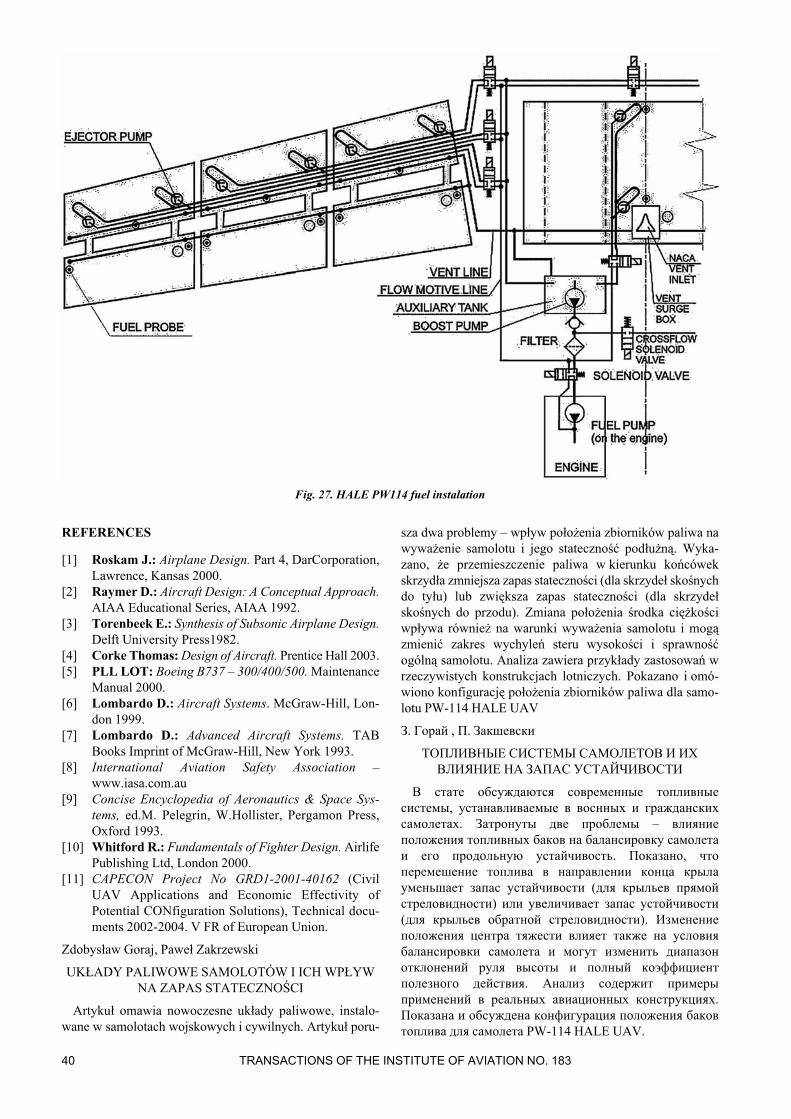
Arrangement of fuel tanks, pipes, pumps, filters and reg-ulators are especially important for long endurance airpla nes,including HALE UAV. Let consider one of such airpla nes,PW-114 developed within CAPECON V FrameworkEuropean Project [11]. Fuel system of PW-114 consists ofseven tanks Fig. 26 and fuel distribution installations, Fig. 27.Engines are supplied by two independent installations. Eachfuel tank is equipped with independent installation consistingof two pumps, system of sensors and venting line. Sensorsare measuring the level of fuel in the limiting points of thetank. Venting line leads to the common valve in the rear ofcentral fuselage section. The fuel is directed to two auxiliarytanks located in the fuselage. Pumps are delivering the fuelfrom the auxiliary tanks to adequate engines. Valves connectall fuel tanks to enable fuel transfer between tanks. Commonvalve for pressure refuelling is located in the fuselage. Over-pressure in the tanks prohibits fuel cavitations.
Tab. 1. Fuel tanks capacity
Fig. 26. PW-114 – fuel tanks[11]
The fuel is located in the integral fuel tanks in the wingtorsion box and in the fuselage between first and third mainframe. Each wing contains three independent tanks and hasan independent installation of pipes. Fuel is used from tanksin the following sequence: from 1st and 4th to gether, thenfrom 2nd and finally from 3rd.
CONCLUSION
Fuel systems are essential for aircraft operation andhighly influence on safety. They must be reliable, redundantand easy to maintain. Very often they may be used to movefuel around the aircraft to keep the center of gravity withinacceptable limits, to maintain pitch and lateral balance andstability. Fuel system also can be used to optimize the wingspan load distribution during flight. It can be achieved due tooptimal tanks allocation and due to empting the tanks in pre-defined order.
Fig. 25. Relaxed stability evaluation obtained by Aerospatiale on a modified experimental Concorde [9]
40 TRANSACTIONS OF THE INSTITUTE OF AVIATION NO. 183
REFERENCES
[1] Roskam J.: Airplane Design. Part 4, DarCorporation,Lawrence, Kansas 2000.
[2] Raymer D.: Aircraft Design: A Conceptual Approach.AIAA Educational Series, AIAA 1992.
[3] Torenbeek E.: Synthesis of Subsonic Airplane Design.Delft University Press1982.
[4] Corke Thomas: Design of Aircraft. Prentice Hall 2003.[5] PLL LOT: Boeing B737 – 300/400/500. Maintenance
Manual 2000.[6] Lombardo D.: Aircraft Systems. McGraw-Hill, Lon -
don 1999.[7] Lombardo D.: Advanced Aircraft Systems. TAB
Books Imprint of McGraw-Hill, New York 1993.[8] International Aviation Safety Association –
www.iasa.com.au[9] Concise Encyclopedia of Aeronautics & Space Sys -
tems, ed.M. Pelegrin, W.Hollister, Pergamon Press,Oxford 1993.
[10] Whitford R.: Fundamentals of Fighter Design. AirlifePublishing Ltd, London 2000.
[11] CAPECON Project No GRD1-2001-40162 (CivilUAV Applications and Economic Effectivity ofPotential CONfiguration Solutions), Technical docu -ments 2002-2004. V FR of European Union.
Zdobysław Goraj, Paweł Zakrzewski
UKŁADY PALIWOWE SAMOLOTÓW I ICH WPŁYWNA ZAPAS STATECZNOŚCI
Artykuł omawia nowoczesne układy paliwowe, instalo -wane w samolotach wojskowych i cywilnych. Artykuł poru -
sza dwa problemy – wpływ położenia zbiorników paliwa nawyważenie samolotu i jego statecz ność podłużną. Wyka -zano, że przemieszczenie paliwa w kierunku końcówekskrzyd ła zmniejsza zapas statecz ności (dla skrzydeł skośnychdo tyłu) lub zwiększa zapas stateczności (dla skrzydełskośnych do przodu). Zmiana położenia środka ciężkościwpływa również na warunki wyważenia samolotu i mogązmienić zakres wychyleń steru wysokości i sprawnośćogólną samolotu. Analiza zawiera przykłady zastosowań wrzeczywistych konstrukcjach lotniczych. Pokazano i omó -wiono konfigurację położenia zbiorników paliwa dla samo -lotu PW-114 HALE UAV
З. Горай , П. Закшевски
ТОПЛИВНЫЕ СИСТЕМЫ САМОЛЕТОВ И ИХВЛИЯНИЕ НА ЗАПАС УСТАЙЧИВОСТИ
В стате обсуждаются современные топливныесистемы, устанавливаемые в воснных и гражданскихсамолетах. Затронуты две проблемы – влияниеположения топливных баков на балансировку самолетаи его продольную устайчивость. Показано, чтоперемешение топлива в направлении конца крылауменьшает запас устайчивости (для крыльев прямойстреловидности) или увеличивает запас устойчивости(для крыльев обратной стреловидности). Изменениеположения центра тяжести влияет также на условиябалансировки самолета и могут изменить диапазонотклонений руля высоты и полный коэффициентполезного действия. Анализ содержит примерыприменений в реальных авиационных конструкциях.Показана и обсуждена конфигурация положения баковтоплива для самолета PW-114 HALE UAV.
Fig. 27. HALE PW114 fuel instalation