aircraft operating instructions for light sport …
TRANSCRIPT
EVEKTOR - AEROTECHNIK a.s. Letecka 1384 Tel.: +420572 537 111 686 04 Kunovice Fax: +420 572 537 900 CZECH REPUBLIC email: [email protected]
Copyright © 2009 EVEKTOR - AEROTECHNIK, a.s.
AIRCRAFT OPERATING INSTRUCTIONS FOR
LIGHT SPORT AIRCRAFT
Serial number: Registration mark: Document number: SSM2008AOIUS Date of issue: March 01, 2009
This manual must be on the airplane board during operation. This manual contains information which must be provided to the pilot and also contains supplementary information provided by the airplane manufacturer - Evektor - Aerotechnik a.s.
This aircraft must be operated in compliance with the information and limitations stated in this manual.

AIRCRAFT OPERATING INSTRUCTIONS
Doc. No. SSM2008AOIUS
March 01, 2009 0-1
Section 0 Technical
Information
CONTENTS
0. TECHNICAL INFORMATION 0.1 Log of Revisions ............................................................0-3
0.2 List of Effective Pages...................................................0-5
0.3 AOI Sections...................................................................0-8

AIRCRAFT OPERATING INSTRUCTIONS
Doc. No. SSM2008AOIUS
March 01, 2009 0-2
Section 0 Technical Information
Intentionally left blank

AIRCRAFT OPERATING INSTRUCTIONS
Doc. No. SSM2008AOIUS
March 01, 2009 0-3
Section 0 Technical
Information
0.1 Log of Revisions All revisions or supplements to this manual, except actual weighing data, are issued in form of revisions, which will have new or changed pages as appendix and the list of which is shown in the Log of Revisons table.
The new or changed text in the revised pages will be marked by means of black vertical line on the margin of page and the revision number and date will be shown on the bottom margin of page.
Rev. No.
Affected Section
Affected Pages
Date Appro-ved
Date Date of Insertion
Sign.
0 ii 1
4 4-7
2/2010
2/2010 Manufact.
AIRCRAFT OPERATING INSTRUCTIONS
Doc. No. SSM2008AOIUS
March 01, 2009 0-4
Section 0 Technical Information
Rev. No.
Affected Section
Affected Pages
Date Appro-ved
Date Date of Insertion
Sign.
AIRCRAFT OPERATING INSTRUCTIONS
Doc. No. SSM2008AOIUS
March 01, 2009 0-5
Section 0 Technical
Information
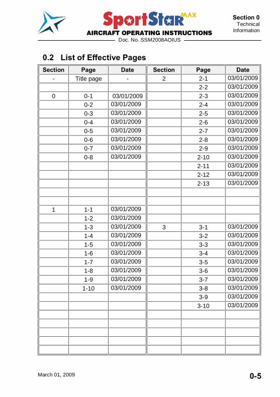
0.2 List of Effective Pages Section Page Date Section Page Date
- Title page - 2 2-1 03/01/2009 2-2 03/01/2009 0 0-1 03/01/2009 2-3 03/01/2009 0-2 03/01/2009 2-4 03/01/2009 0-3 03/01/2009 2-5 03/01/2009 0-4 03/01/2009 2-6 03/01/2009 0-5 03/01/2009 2-7 03/01/2009 0-6 03/01/2009 2-8 03/01/2009 0-7 03/01/2009 2-9 03/01/2009 0-8 03/01/2009 2-10 03/01/2009 2-11 03/01/2009 2-12 03/01/2009 2-13 03/01/2009
1 1-1 03/01/2009
1-2 03/01/2009
1-3 03/01/2009 3 3-1 03/01/2009 1-4 03/01/2009 3-2 03/01/2009 1-5 03/01/2009 3-3 03/01/2009 1-6 03/01/2009 3-4 03/01/2009 1-7 03/01/2009 3-5 03/01/2009 1-8 03/01/2009 3-6 03/01/2009 1-9 03/01/2009 3-7 03/01/2009 1-10 03/01/2009 3-8 03/01/2009 3-9 03/01/2009 3-10 03/01/2009

AIRCRAFT OPERATING INSTRUCTIONS
Doc. No. SSM2008AOIUS
March 01, 2009 0-6
Section 0 Technical Information
Section Page Date Section Page Date 4 4-1 03/01/2009 5 5-12 03/01/2009 4-2 03/01/2009 5-13 03/01/2009 4-3 03/01/2009 5-14 03/01/2009 4-4 03/01/2009 5-15 03/01/2009 4-5 03/01/2009 5-16 03/01/2009 4-6 03/01/2009
4-7 03/01/2009 4-8 03/01/2009
4-9 03/01/2009 6 6-1 03/01/2009 4-10 03/01/2009 6-2 03/01/2009
4-11 03/01/2009 6-3 03/01/2009 4-12 03/01/2009 6-4 03/01/2009
4-13 03/01/2009 6-5 03/01/2009 4-14 03/01/2009 6-6 03/01/2009 4-15 03/01/2009 6-7 03/01/2009 4-16 03/01/2009 6-8 03/01/2009 4-17 03/01/2009 6-9 03/01/2009 4-18 03/01/2009 6-10 03/01/2009 6-11 03/01/2009
6-12 03/01/2009 6-13 03/01/2009 6-14 03/01/2009
5 5-1 03/01/2009
5-2 03/01/2009 5-3 03/01/2009
5-4 03/01/2009 5-5 03/01/2009
5-6 03/01/2009 5-7 03/01/2009
5-8 03/01/2009
5-9 03/01/2009 5-10 03/01/2009
5-11 03/01/2009
AIRCRAFT OPERATING INSTRUCTIONS
Doc. No. SSM2008AOIUS
March 01, 2009 0-7
Section 0 Technical
Information
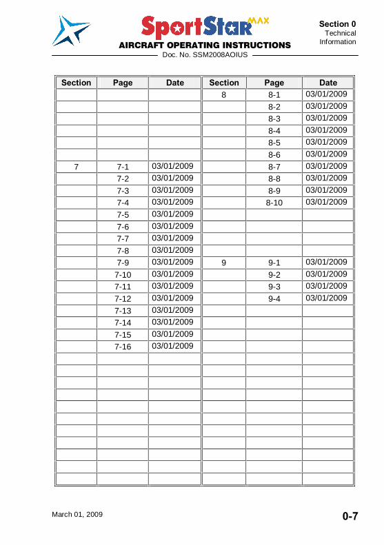
Section Page Date Section Page Date
8 8-1 03/01/2009 8-2 03/01/2009 8-3 03/01/2009 8-4 03/01/2009 8-5 03/01/2009 8-6 03/01/2009
7 7-1 03/01/2009 8-7 03/01/2009 7-2 03/01/2009 8-8 03/01/2009 7-3 03/01/2009 8-9 03/01/2009 7-4 03/01/2009 8-10 03/01/2009 7-5 03/01/2009
7-6 03/01/2009 7-7 03/01/2009
7-8 03/01/2009 7-9 03/01/2009 9 9-1 03/01/2009 7-10 03/01/2009 9-2 03/01/2009 7-11 03/01/2009 9-3 03/01/2009
7-12 03/01/2009 9-4 03/01/2009 7-13 03/01/2009
7-14 03/01/2009
7-15 03/01/2009 7-16 03/01/2009
AIRCRAFT OPERATING INSTRUCTIONS
Doc. No. SSM2008AOIUS
March 01, 2009 0-8
Section 0 Technical Information
0.3 AOI Sections Section
GENERAL ..............................................................................1 LIMITATIONS ........................................................................2 EMERGENCY PROCEDURES ...............................................3 NORMAL PROCEDURES ......................................................4 PERFORMANCE ...................................................................5 WEIGHT AND BALANCE ......................................................6 AIRPLANE AND SYSTEM DESCRIPTION ............................7 AIRPLANE HANDLING, SERVICING AND MAINTENANCE .............................................................8 SUPPLEMENTS......................................................................9

AIRCRAFT OPERATING INSTRUCTIONS
Doc. No. SSM2008AOIUS
March 01, 2009 1-1
Section 1 General
SECTION 1
1. GENERAL 1.1 Introduction ....................................................................1-3
1.2 Certification basis ..........................................................1-3 1.2.1 Data location..................................................................... 1-4
1.3 Warnings, cautions, notes.............................................1-4
1.4 Descriptive data .............................................................1-5 1.4.1 Airplane description........................................................... 1-5 1.4.2 Powerplant........................................................................ 1-5 1.4.3 Main technical data ........................................................... 1-6 1.4.4 Three-view drawing........................................................... 1-7
1.5 Definitions and abbreviations .......................................1-8
AIRCRAFT OPERATING INSTRUCTIONS
Doc. No. SSM2008AOIUS
March 01, 2009 1-2
Section 1 General
Intentionally left blank
AIRCRAFT OPERATING INSTRUCTIONS
Doc. No. SSM2008AOIUS
March 01, 2009 1-3
Section 1 General
1.1 Introduction PARTICIPANT�S RESPONSIBILITY There are inherent risks in participating in aviation activities, these risks are significant, up to and potentially including death. Operators and passengers of recreational aviation aircraft, by participation, accept the risks inherent in such participation of which the ordinary prudent person is or should be aware. Pilots and passengers have a duty to excersise good judgment and act in a responsible manner while using the aircraft and to obey all oral or written warnings, or both, prior to and/or during use of the aircraft. This Aircraft Operating Instructions has been prepared to provide pilots and instructors with information for safe and efficient operation of the SportStar MAX airplane. It also contains supplementary information considered to be important by the airplane manufacturer.
1.2 Certification basis SportStar MAX complies with the ASTM F2245-07a Standard Specification for Design and Performance of a Light Sport Airplane, issued by ASTM International Committee F37.
IFR version complies with FAR 91.205 requirements, as well as with F2245 Annex A3 Additional Requirements for Light Sport Airplanes Operated Under Instrument Flight Rules, as known till 1.1.2009.
AIRCRAFT OPERATING INSTRUCTIONS
Doc. No. SSM2008AOIUS
March 01, 2009 1-4
Section 1 General
1.2.1 Data location The certification documentation is available from the US General importer or airplane manufacturer on a request of competent aviation authority and/or Designated Airworthiness Representative.
Contact address: US General Importer: Evektor Aircraft Inc. 1415 General Aviation Dr. Hangar # 22 Melbourne, FL 32935 (321) 206-0535 office [email protected]
Airplane Manufacturer: Evektor - Aerotechnik, a.s. Letecká 1384 686 04 Kunovice Czech Republic tel.:+420 572 537 111 fax:+420 572 537 900 e-mail:[email protected]
1.3 Warnings, cautions, notes The following informations apply to warnings, cautions and notes used in the Aircraft Operating Instructions:
WARNING MEANS THAT NON-OBSERVATIONS OF THE CORRESPONDING PROCEDURE LEADS TO AN IMMEADIATE OR IMPORTENT DEGRADATION OF THE FLIGHT SAFETY.
CAUTION MEANS THAT NON-OBSERVATIONS OF THE CORRESPONDING PROCEDURE LEADS TO A MINOR OR TO A MORE OR LESS LONG TERM DEGRADATION OF THE FLIGHT SAFETY.
NOTE Draws the attention to any special item not directly related to safety but which is important or unusual.
AIRCRAFT OPERATING INSTRUCTIONS
Doc. No. SSM2008AOIUS
March 01, 2009 1-5
Section 1 General
1.4 Descriptive data
1.4.1 Airplane description SportStar MAX airplane is a metal-composite low-wing monoplane of semimonocoque structure with two side by side seats and steerable nose wheel landing gear.
For further description see Section 7 - Airplane and system description.
1.4.2 Powerplant The standard powerplant consists of ROTAX 912ULS (100 hp) engine and ground adjustable, 3-bladed, WOODCOMP KLASSIC 170/3/R propeller.
IFR version is fitted with certified ROTAX 912S2 engine and ground adjustable, 3-bladed, composite Warpdrive CF prop, with Nickel protection of blade leading edges.
For further description see Section 7 - Airplane and system description.
For particular engine and propeller type - see Section 9 - Supplements - Airplane description.

AIRCRAFT OPERATING INSTRUCTIONS
Doc. No. SSM2008AOIUS
March 01, 2009 1-6
Section 1 General
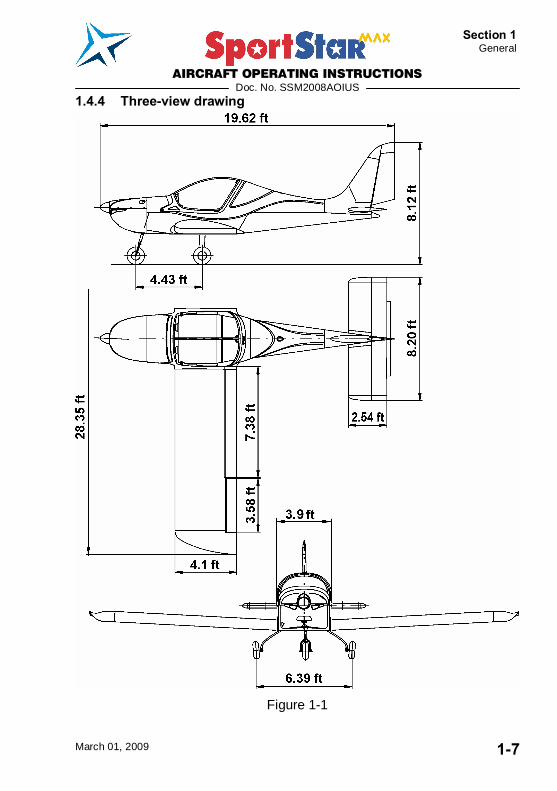
1.4.3 Main technical data Wing
Span 28.37 ft Area 112.7 sq.ft MAC depth 4.1 ft Wing loading 11.71 lbs/sq.ft Aileron - area 2.62 sq.ft Flap - area 5.60 sq.ft
Fuselage
length 19.62 ft width 3.55 ft height 8.12 ft cockpit canopy max. width 3.9 ft
Horizontal tail unit
Span 8.20 ft HTU Area 20.88 sq.ft Elevator area 8.40 sq.ft
Vertical tail unit
Height 4.21 ft VTU Area 10.93 sq.ft Rudder area 4.67 sq.ft
Landing gear
Wheel track 6.39 ft Wheel base 4.43 ft Nose and main landing gear wheel diameter 15 in
AIRCRAFT OPERATING INSTRUCTIONS
Doc. No. SSM2008AOIUS
March 01, 2009 1-7
Section 1 General
1.4.4 Three-view drawing
Figure 1-1

AIRCRAFT OPERATING INSTRUCTIONS
Doc. No. SSM2008AOIUS
March 01, 2009 1-8
Section 1 General
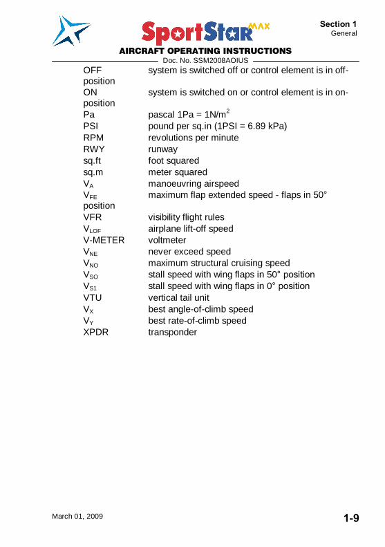
1.5 Definitions and abbreviations NOTE
The abbreviations on placards in the airplane cockpit, are printed in BOLD CAPITAL LETTERS in the text of this Aircraft Operating Instructions.
ACCU accumulator ALT ENC encoding altimeter ATC air traffic control bar bar 1 bar = 100 kPa BEACON anti-collision beacon °C Celsius degree CAS calibrated airspeed CLOCK aircraft clock ft foot 1 ft = 0.305 m GPS global positioning system HTU horizontal tail unit IAS indicated airspeed IC intercom IFR instrument flight rules ISA international standard atmosphere kg kilogram KIAS indicated airspeed in knots KCAS calibrated airspeed in knots mph mile per hour mph CAS calibrated airspeed in miles per hour km/h CAS calibrated airspeed in km/h kts knots 1 kt = 1.852 km/h litres litre lbs pounds 1 lb = 0.45 kg m meter MAC mean aerodynamical chord max. maximum min. minimum or minute mm milimeter m/s meter per second OAT outside air temperature
AIRCRAFT OPERATING INSTRUCTIONS
Doc. No. SSM2008AOIUS
March 01, 2009 1-9
Section 1 General
OFF system is switched off or control element is in off-position ON system is switched on or control element is in on-position Pa pascal 1Pa = 1N/m2
PSI pound per sq.in (1PSI = 6.89 kPa) RPM revolutions per minute RWY runway sq.ft foot squared sq.m meter squared VA manoeuvring airspeed VFE maximum flap extended speed - flaps in 50° position VFR visibility flight rules VLOF airplane lift-off speed V-METER voltmeter VNE never exceed speed VNO maximum structural cruising speed VSO stall speed with wing flaps in 50° position VS1 stall speed with wing flaps in 0° position VTU vertical tail unit VX best angle-of-climb speed VY best rate-of-climb speed XPDR transponder

AIRCRAFT OPERATING INSTRUCTIONS
Doc. No. SSM2008AOIUS
March 01, 2009 1-10
Section 1 General
Intentionally left blank
AIRCRAFT OPERATING INSTRUCTIONS
Doc. No. SSM2008AOIUS
March 01, 2009 2-1
Section 2 Limitations
SECTION 2
2. LIMITATIONS 2.1 Introduction ....................................................................2-3
2.2 Airspeed .........................................................................2-3
2.3 Airspeed indicator marking...........................................2-4
2.4 Powerplant......................................................................2-5
2.5 Powerplant instrument marking....................................2-6
2.6 Miscellaneous instrument marking...............................2-6
2.7 Weight.............................................................................2-6
2.8 Centre of gravity.............................................................2-6
2.9 Approved manoeuvres ..................................................2-7
2.10 Manoeuvring load factors..............................................2-7
2.11 Flight crew......................................................................2-7
2.12 Kinds of operation .........................................................2-8
2.13 Fuel .................................................................................2-9
2.14 Oil..................................................................................2-10
2.15 Maximum number of passengers ...............................2-10
2.16 Other limitations...........................................................2-10
2.17 Limitation placards ......................................................2-11

AIRCRAFT OPERATING INSTRUCTIONS
Doc. No. SSM2008AOIUS
March 01, 2009 2-2
Section 2 Limitations
Intentionally left blank

AIRCRAFT OPERATING INSTRUCTIONS
Doc. No. SSM2008AOIUS
March 01, 2009 2-3
Section 2 Limitations
2.1 Introduction Section 2 contains operation limitation, instrument marking and basic placards necessary for safe operation of airplane and its engine, standard systems and equipment. Limitation for optional systems and equipment are stated in section 9 - Supplements.
2.2 Airspeed Airspeed limitations and their meaning for operation are stated in the table below:
Speed KIAS mph IAS Meaning
VNE Never exceed speed
146 168 Do not exceed this speed in any operation.
VNO Maximum structural cruising speed
115 132 Do not exceed this speed, with exception of flight in smooth air, and even then only with increased caution.
VA Manoeuvring speed
90 106 Do not make full or abrupt control movement above this speed, because under certain conditions the aircraft may be overstressed by full control movement.
VFE Maximum flap extended speed
70 81 Do not exceed this speed with the given flap setting.
AIRCRAFT OPERATING INSTRUCTIONS
Doc. No. SSM2008AOIUS
March 01, 2009 2-4
Section 2 Limitations
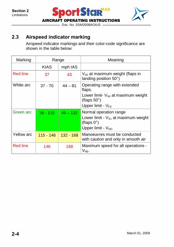
2.3 Airspeed indicator marking Airspeed indicator markings and their color-code significance are shown in the table below:
Marking Range Meaning KIAS mph IAS
Red line 37 43 VS0 at maximum weight (flaps in landing position 50°)
White arc 37 - 70 44 � 81 Operating range with extended flaps. Lower limit- VS0 at maximum weight (flaps 50°) Upper limit - VFE
Green arc 38 - 115 49 � 132 Normal operation range Lower limit - VS1 at maximum weight (flaps 0°) Upper limit - VNO
Yellow arc 115 - 146 132 - 168 Manoeuvres must be conducted with caution and only in smooth air
Red line 146 168 Maximum speed for all operations - VNE.
AIRCRAFT OPERATING INSTRUCTIONS
Doc. No. SSM2008AOIUS
March 01, 2009 2-5
Section 2 Limitations
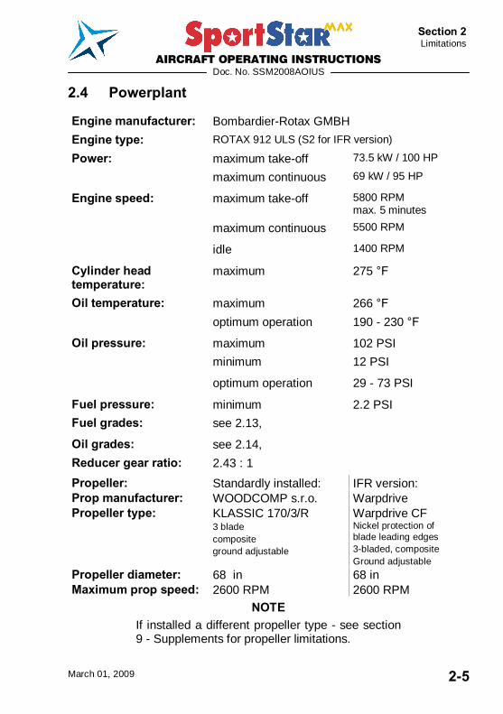
2.4 Powerplant Engine manufacturer: Bombardier-Rotax GMBH
Engine type: ROTAX 912 ULS (S2 for IFR version) Power: maximum take-off 73.5 kW / 100 HP
maximum continuous 69 kW / 95 HP
Engine speed: maximum take-off 5800 RPM max. 5 minutes
maximum continuous 5500 RPM
idle 1400 RPM
Cylinder head temperature:
maximum 275 °F
Oil temperature: maximum 266 °F
optimum operation 190 - 230 °F
Oil pressure: maximum 102 PSI
minimum 12 PSI
optimum operation 29 - 73 PSI
Fuel pressure: minimum 2.2 PSI
Fuel grades: see 2.13, Oil grades: see 2.14,
Reducer gear ratio: 2.43 : 1 Propeller: Standardly installed: IFR version: Prop manufacturer: WOODCOMP s.r.o. Warpdrive Propeller type: KLASSIC 170/3/R
3 blade composite ground adjustable
Warpdrive CF Nickel protection of blade leading edges 3-bladed, composite Ground adjustable
Propeller diameter: 68 in 68 in Maximum prop speed: 2600 RPM 2600 RPM
NOTE If installed a different propeller type - see section 9 - Supplements for propeller limitations.

AIRCRAFT OPERATING INSTRUCTIONS
Doc. No. SSM2008AOIUS
March 01, 2009 2-6
Section 2 Limitations
2.5 Powerplant instrument marking The colour-code of instruments is shown in the following table:
Red line Green arc Yellow arc Red line
Instrument Units Lower limit
Normal operation
range
Caution range
Upper limit
RPM indicator RPM - 1400 - 5500 5500 - 5800 5800
Oil temperature indicator
°F - 190 - 230 120 - 190
230 - 266
266
Oil pressure indicator
PSI 12 29 - 73 12 - 29
73 - 102
102
Cylinder head temperature
°F - - - 275
2.6 Miscellaneous instrument marking There are not other instruments with colour marking.
2.7 Weight Empty weight (average equipment) 740 lbs ± 2 %
Maximum take-off weight 1320 lbs
Maximum landing weight 1320 lbs
Maximum weight in baggage compartment 55 lbs
WARNING DO NOT EXCEED MAXIMUM WEIGHTS! THEIR EXCEEDING LEADS TO AIRPLANE OVERLOADING AND TO DEGRADATION OF FLIGHT CHARACTERISTICS AND DETERIORATION OF MANOEUVRABILITY.
2.8 Centre of gravity Empty airplane C.G. position 20 ± 2 %MAC (standard equipment)
AIRCRAFT OPERATING INSTRUCTIONS
Doc. No. SSM2008AOIUS
March 01, 2009 2-7
Section 2 Limitations
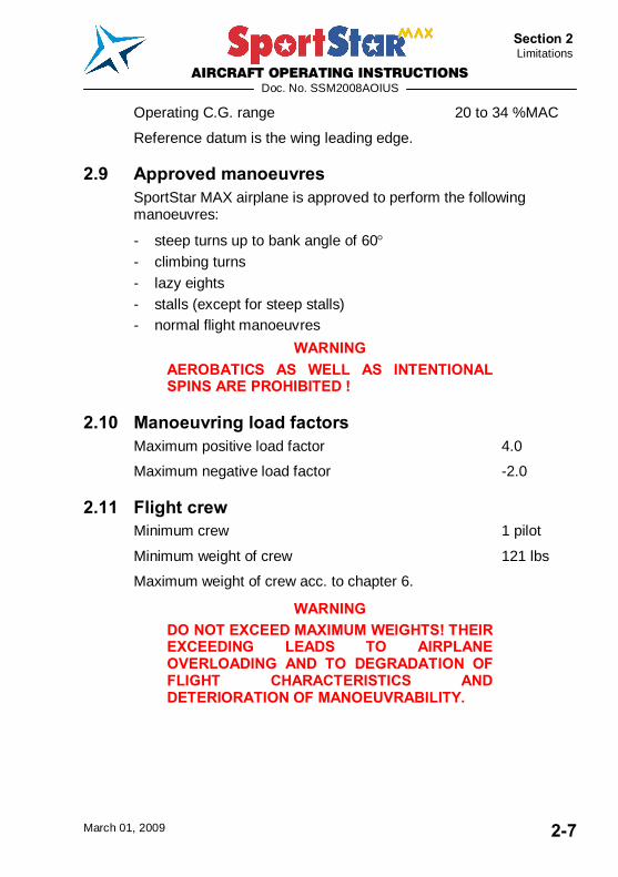
Operating C.G. range 20 to 34 %MAC
Reference datum is the wing leading edge.
2.9 Approved manoeuvres SportStar MAX airplane is approved to perform the following manoeuvres:
- steep turns up to bank angle of 60 - climbing turns - lazy eights - stalls (except for steep stalls) - normal flight manoeuvres
WARNING AEROBATICS AS WELL AS INTENTIONAL SPINS ARE PROHIBITED !
2.10 Manoeuvring load factors Maximum positive load factor 4.0
Maximum negative load factor -2.0
2.11 Flight crew Minimum crew 1 pilot
Minimum weight of crew 121 lbs
Maximum weight of crew acc. to chapter 6.
WARNING DO NOT EXCEED MAXIMUM WEIGHTS! THEIR EXCEEDING LEADS TO AIRPLANE OVERLOADING AND TO DEGRADATION OF FLIGHT CHARACTERISTICS AND DETERIORATION OF MANOEUVRABILITY.
AIRCRAFT OPERATING INSTRUCTIONS
Doc. No. SSM2008AOIUS
March 01, 2009 2-8
Section 2 Limitations
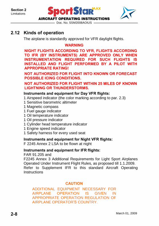
2.12 Kinds of operation The airplane is standardly approved for VFR daylight flights.
WARNING NIGHT FLIGHTS ACCORDING TO VFR, FLIGHTS ACCORDING TO IFR (BY INSTRUMENTS) ARE APPROVED ONLY WHEN INSTRUMENTATION REQUIRED FOR SUCH FLIGHTS IS INSTALLED AND FLIGHT PERFORMED BY A PILOT WITH APPROPRIATE RATING! NOT AUTHORIZED FOR FLIGHT INTO KNOWN OR FORECAST POSSIBLE ICING CONDITIONS. NOT AUTHORIZED FOR FLIGHT WITHIN 25 MILES OF KNOWN LIGHTNING OR THUNDERSTORMS. Instruments and equipment for Day VFR flights: 1 Airspeed indicator (the color marking according to par. 2.3) 1 Sensitive barometric altimeter 1 Magnetic compass 1 Fuel gauge indicator 1 Oil temperature indicator 1 Oil pressure indicator 1 Cylinder head temperature indicator 1 Engine speed indicator 1 Safety harness for every used seat
Instruments and equipment for Night VFR flights: F 2245 Annex 2 LSA to be flown at night
Instruments and equipment for IFR flights: FAR 91.205 and F2245 Annex 3 Additional Requirements for Light Sport Airplanes Operated Under Instrument Flight Rules, as proposed till 1.1.2009. Refer to Supplement IFR to this standard Aircraft Operating Instructions
CAUTION ADDITIONAL EQUIPMENT NECESSARY FOR AIRPLANE OPERATION IS GIVEN IN APPROPRIATE OPERATION REGULATION OF AIRPLANE OPERATOR�S COUNTRY.
AIRCRAFT OPERATING INSTRUCTIONS
Doc. No. SSM2008AOIUS
March 01, 2009 2-9
Section 2 Limitations
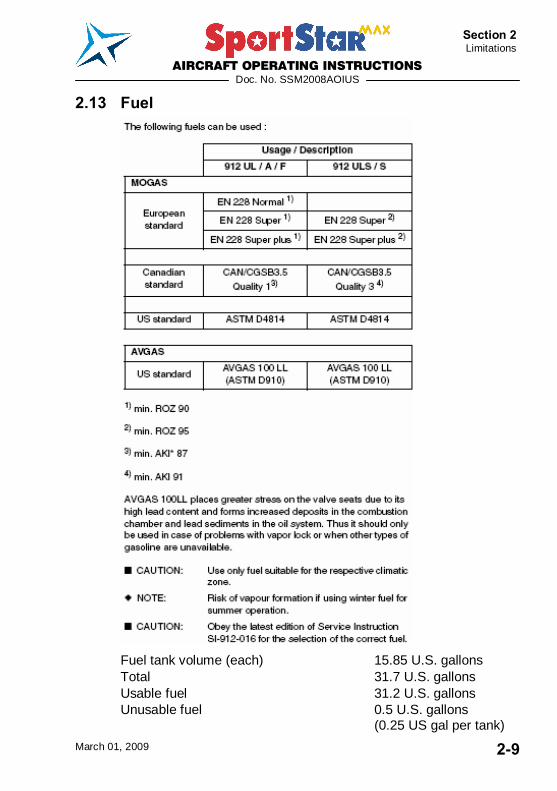
2.13 Fuel
Fuel tank volume (each) 15.85 U.S. gallons Total 31.7 U.S. gallons Usable fuel 31.2 U.S. gallons Unusable fuel 0.5 U.S. gallons (0.25 US gal per tank)
AIRCRAFT OPERATING INSTRUCTIONS
Doc. No. SSM2008AOIUS
March 01, 2009 2-10
Section 2 Limitations
NOTE It is not recommended to fully tank the fuel tanks. Due to fuel thermal expansion keep about 2.11U.S. gallons of free space in the tank to prevent fuel bleed through the vents in the wing tips thus preventing environmental contamination. This should be adhered especially when cold fuel from an underground tank is tanked.
2.14 Oil Performance classification SF, SG according to API
Oil volume:
- minimum 0.53 U.S. gallons - maximum 0.79 U.S. gallons
2.15 Maximum number of passengers Maximum number of passengers including pilot 2
2.16 Other limitations SMOKING IS PROHIBITED on the airplane board.
PASSENGER NOTICE This aircraft conforms to ASTM Consensus Standards of airworthiness developed and maintained by the aviation community under ASTM Technical Committee F37.
PASSENGER WARNING ! This aircraft was manufactured in accordance with Light Sport Aircraft airworthiness standards and does not conform to standard category airworthiness requirements.
AIRCRAFT OPERATING INSTRUCTIONS
Doc. No. SSM2008AOIUS
March 01, 2009 2-11
Section 2 Limitations
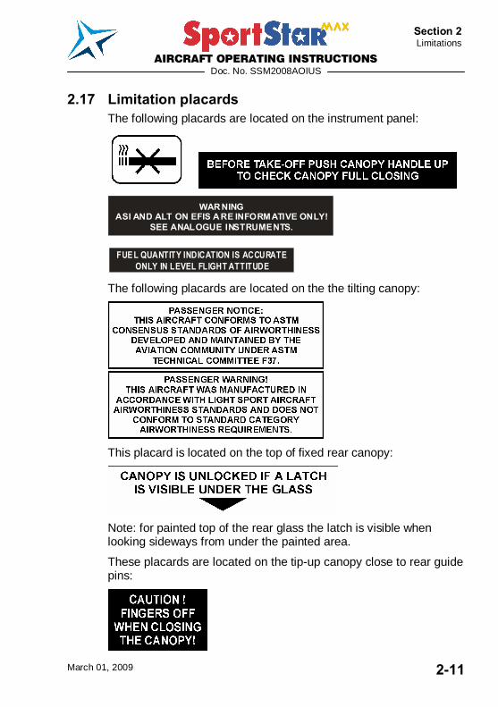
2.17 Limitation placards The following placards are located on the instrument panel: The following placard is located on the instrument panel:
WARNINGASI AND ALT ON EFIS ARE INFORMATIVE ONLY!
SEE ANALOGUE INSTRUMENTS.
FUEL QUANTITY INDICATION IS ACCURATE ONLY IN LEVEL FLIGHT ATTITUDE
The following placards are located on the the tilting canopy:
This placard is located on the top of fixed rear canopy:
Note: for painted top of the rear glass the latch is visible when looking sideways from under the painted area.
These placards are located on the tip-up canopy close to rear guide pins:
AIRCRAFT OPERATING INSTRUCTIONS
Doc. No. SSM2008AOIUS
March 01, 2009 2-12
Section 2 Limitations
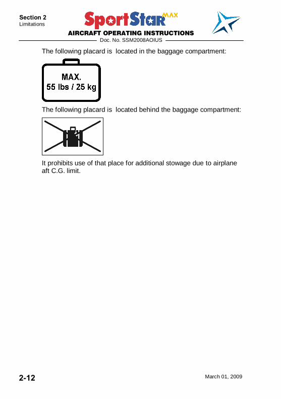
The following placard is located in the baggage compartment:
The following placard is located behind the baggage compartment:
It prohibits use of that place for additional stowage due to airplane aft C.G. limit.
AIRCRAFT OPERATING INSTRUCTIONS
Doc. No. SSM2008AOIUS
March 01, 2009 2-13
Section 2 Limitations
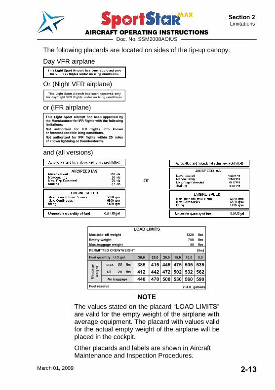
The following placards are located on sides of the tip-up canopy:
Day VFR airplane
Or (Night VFR airplane)
or (IFR airplane)
and (all versions)
Max.take-off weight 1320 lbs Empty weight 700 lbs Max.baggage weight 55 lbs
PERMITTED CREW WEIGHT [lbs]
30,0 25,0 20,0 15,0 10,0 5,0
max. 55 lbs 385 415 445 475 505 5351/2 28 lbs 412 442 472 502 532 562No baggage 440 470 500 530 560 590
Fuel reserve 2 U.S. gallons
Fuel quantity U.S.gal.
Bag
gage
w
eigh
t
LOAD LIMITS
NOTE The values stated on the placard �LOAD LIMITS� are valid for the empty weight of the airplane with average equipment. The placard with values valid for the actual empty weight of the airplane will be placed in the cockpit.
Other placards and labels are shown in Aircraft Maintenance and Inspection Procedures.
This Light Sport Aircraft has been approved by the Manufacturer for IFR flights with the following limitations: Not authorized for IFR flights into known or forecast possible icing conditions. Not authorized for IFR flights within 25 miles of known lightning or thunderstorms.
or

AIRCRAFT OPERATING INSTRUCTIONS
Doc. No. SSM2008AOIUS
March 01, 2009 3-1
Section 3 Emergency Procedures
SECTION 3
3. EMERGENCY PROCEDURES 3.1 Introduction ....................................................................3-3
3.2 Speeds for performing emergency procedures...........3-3
3.3 Engine failure .................................................................3-3 3.3.1 Engine failure at take-off run ............................................. 3-3 3.3.2 Engine failure at take-off ................................................... 3-3 3.3.3 Engine failure in flight........................................................ 3-4
3.4 Engine starting at flight .................................................3-4
3.5 Engine fire ......................................................................3-5 3.5.1 Fire on the ground............................................................. 3-5 3.5.2 Fire during take-off ............................................................ 3-5 3.5.3 Fire in flight ....................................................................... 3-6
3.6 Fire in the cockpit (if manual extinguisher available aboard) .....................................................................................3-7
3.7 Gliding flight...................................................................3-7
3.8 Emergency landing ........................................................3-8 3.8.1 Emergency landing - with non-operating engine ................ 3-8 3.8.2 Safety landing- with engine operating................................ 3-8 3.8.3 Landing with burst tire ....................................................... 3-9 3.8.4 Landing with damaged landing gear .................................. 3-9
3.9 Unintentional spin recovery ..........................................3-9
3.10 Other emergency procedures .....................................3-10 3.10.1 Vibration ......................................................................... 3-10 3.10.2 Carburettor icing ............................................................. 3-10
AIRCRAFT OPERATING INSTRUCTIONS
Doc. No. SSM2008AOIUS
March 01, 2009 3-2
Section 3 Emergency Procedures
Intentionally left blank
AIRCRAFT OPERATING INSTRUCTIONS
Doc. No. SSM2008AOIUS
March 01, 2009 3-3
Section 3 Emergency Procedures
3.1 Introduction Section 3 describes operations and procedures for emergency situation solutions that could possibly occur during airplane operation.
3.2 Speeds for performing emergency procedures Airspeed for the best gliding ratio 59 KIAS (68 mph IAS) (flaps retracted)
Precautionary landing 55 KIAS (63 mph IAS) (engine running, flaps in landing position - 50°)
Emergency landing 55 KIAS (63 mph IAS) (engine stopped, flaps in landing position - 50°)
3.3 Engine failure
3.3.1 Engine failure at take-off run 1. THROTTLE lever idle
2. Brakes as necessary
3. FUEL SELECTOR OFF
4. Ignition OFF
5. Master switch OFF
3.3.2 Engine failure at take-off 1. Gliding speed:
with flaps in take-off position (15°) min. 55 KIAS (63 mph IAS) with flaps retracted (0°) min. 59 KIAS (68 mph IAS)
2. Altitude:
- Land in take-off direction if below 150 ft: - Land in take-off direction or you can perform turn up to 90°
if altitude is 150 - 400 ft: - You can try start engine if altitude is above 250 ft - You can perform turn up to 180° if altitude is above 400 ft:
3. THROTTLE lever idle
AIRCRAFT OPERATING INSTRUCTIONS
Doc. No. SSM2008AOIUS
March 01, 2009 3-4
Section 3 Emergency Procedures
4. Flaps as needed
5. FUEL SELECTOR OFF
6. Ignition OFF
7. ATC report
8. Master switch OFF
9. After touch down brake as needed
3.3.3 Engine failure in flight 1. Gliding speed 59 KIAS (68 mph IAS)
2. Altitude take a decision and carry out:
- Engine starting in flight - paragraph 3.4 - Emergency landing - paragraph 3.8.1
3.4 Engine starting at flight NOTE
It is possible to start the engine by means of the starter within the whole range of operation speeds as well as flight altitudes. The engine started up immediately after switching the ignition to START position.
If the engine is shut down, the altitude loss during engine starting can reach up to 1000 ft.
1. Gliding speed 59 KIAS (68 mph IAS)
2. Altitude check
3. Master switch ON
4. Unnecessary electrical equipment switch off
5. FUEL SELECTOR LEFT 6. Choke as needed
7. THROTTLE lever idle (choke opened) or increased idle (choke closed)
AIRCRAFT OPERATING INSTRUCTIONS
Doc. No. SSM2008AOIUS
March 01, 2009 3-5
Section 3 Emergency Procedures
The propeller is rotating:
8. Ignition BOTH
The propeller is not rotating:
9. Ignition START
10. If engine starting does not occur, increase gliding speed up to 108 KIAS (124 mph IAS) (see NOTE), so that air-flow turns the propeller and engine will start.
11. Ignition BOTH
12. If engine starting is unsuccessful, then continue according to paragraph 3.8.1 Emergency landing.
3.5 Engine fire
3.5.1 Fire on the ground 1. FUEL SELECTOR OFF 2. Brakes brake
3. THROTTLE lever full
4. HOT AIR knob (if installed) push
After the engine stops: 5. Ignition OFF
6. Master switch OFF
7. Airplane leave
8. Manual extinguisher (if available) use
3.5.2 Fire during take-off 1. FUEL SELECTOR OFF 2. THROTTLE lever full
3. Airspeed 65 KIAS (75 mph IAS)
4. HOT AIR knob (if installed) push
5. COLD AIR knob (if installed) push
After the engine stops:
AIRCRAFT OPERATING INSTRUCTIONS
Doc. No. SSM2008AOIUS
March 01, 2009 3-6
Section 3 Emergency Procedures
6. Gliding speed 55 KIAS (63 mph IAS)
7. Ignition OFF
8. Master switch OFF
9. Land
10. Airplane leave
11. Manual extinguisher (if available) use
3.5.3 Fire in flight 1. FUEL SELECTOR OFF 2. THROTTLE lever full
3. HOT AIR knob (if installed) push
4. COLD AIR knob (if installed) push
5. Gliding speed 59 KIAS (68 mph IAS)
6. Ignition OFF
7. ATC report if possible
8. Master switch OFF
NOTE For extinguishing the engine fire, you can perform slip under assumption that you have sufficient altitude and time.
WARNING AFTER EXTINGUISHING THE ENGINE FIRE START ENGINE ONLY IF IT NECESSARY TO SAFE LANDING. FUEL LEAK IN ENGINE COMPARTMENT COULD CAUSE FIRE AND FIRE COULD RESTORE AGAIN.
9. If you start engine again, switch off all switches, switch on the Master switch, and then subsequently switch on only equipment necessary to safe landing.
10. Emergency landing carry out according to paragraph 3.8.1
11. Airplaine leave
AIRCRAFT OPERATING INSTRUCTIONS
Doc. No. SSM2008AOIUS
March 01, 2009 3-7
Section 3 Emergency Procedures
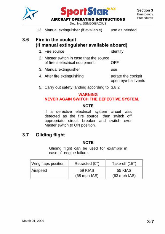
12. Manual extinguisher (if available) use as needed
3.6 Fire in the cockpit (if manual extinguisher available aboard)
1. Fire source identify
2. Master switch in case that the source of fire is electrical equipment. OFF
3. Manual extinguisher use
4. After fire extinguishing aerate the cockpit open eye-ball vents
5. Carry out safety landing according to 3.8.2
WARNING NEVER AGAIN SWITCH THE DEFECTIVE SYSTEM.
NOTE If a defective electrical system circuit was detected as the fire source, then switch off appropriate circuit breaker and switch over Master switch to ON position.
3.7 Gliding flight NOTE
Gliding flight can be used for example in case of engine failure.
Wing flaps position Retracted (0°) Take-off (15°)
Airspeed 59 KIAS (68 mph IAS)
55 KIAS (63 mph IAS)
AIRCRAFT OPERATING INSTRUCTIONS
Doc. No. SSM2008AOIUS
March 01, 2009 3-8
Section 3 Emergency Procedures
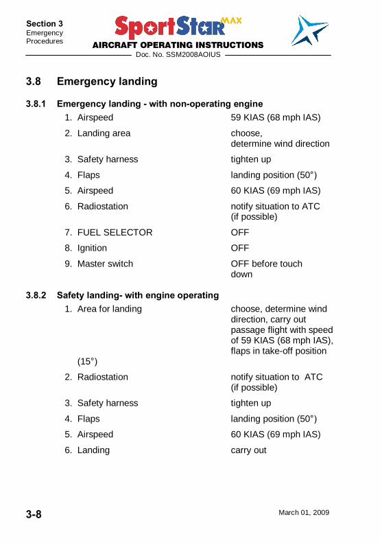
3.8 Emergency landing
3.8.1 Emergency landing - with non-operating engine 1. Airspeed 59 KIAS (68 mph IAS)
2. Landing area choose, determine wind direction
3. Safety harness tighten up
4. Flaps landing position (50°)
5. Airspeed 60 KIAS (69 mph IAS)
6. Radiostation notify situation to ATC (if possible)
7. FUEL SELECTOR OFF 8. Ignition OFF
9. Master switch OFF before touch down
3.8.2 Safety landing- with engine operating 1. Area for landing choose, determine wind
direction, carry out passage flight with speed of 59 KIAS (68 mph IAS), flaps in take-off position (15°)
2. Radiostation notify situation to ATC (if possible)
3. Safety harness tighten up
4. Flaps landing position (50°)
5. Airspeed 60 KIAS (69 mph IAS)
6. Landing carry out
AIRCRAFT OPERATING INSTRUCTIONS
Doc. No. SSM2008AOIUS
March 01, 2009 3-9
Section 3 Emergency Procedures
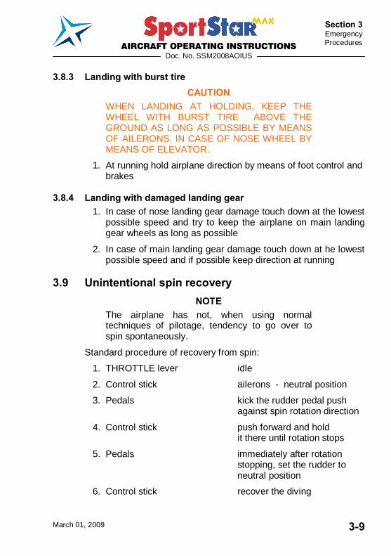
3.8.3 Landing with burst tire CAUTION
WHEN LANDING AT HOLDING, KEEP THE WHEEL WITH BURST TIRE ABOVE THE GROUND AS LONG AS POSSIBLE BY MEANS OF AILERONS. IN CASE OF NOSE WHEEL BY MEANS OF ELEVATOR.
1. At running hold airplane direction by means of foot control and brakes
3.8.4 Landing with damaged landing gear 1. In case of nose landing gear damage touch down at the lowest
possible speed and try to keep the airplane on main landing gear wheels as long as possible
2. In case of main landing gear damage touch down at he lowest possible speed and if possible keep direction at running
3.9 Unintentional spin recovery NOTE
The airplane has not, when using normal techniques of pilotage, tendency to go over to spin spontaneously.
Standard procedure of recovery from spin:
1. THROTTLE lever idle
2. Control stick ailerons - neutral position
3. Pedals kick the rudder pedal push against spin rotation direction
4. Control stick push forward and hold it there until rotation stops
5. Pedals immediately after rotation stopping, set the rudder to neutral position
6. Control stick recover the diving
AIRCRAFT OPERATING INSTRUCTIONS
Doc. No. SSM2008AOIUS
March 01, 2009 3-10
Section 3 Emergency Procedures
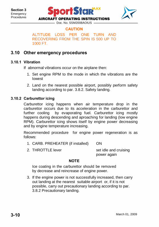
CAUTION ALTITUDE LOSS PER ONE TURN AND RECOVERING FROM THE SPIN IS 500 UP TO 1000 FT.
3.10 Other emergency procedures
3.10.1 Vibration If abnormal vibrations occur on the airplane then:
1. Set engine RPM to the mode in which the vibrations are the lowest
2. Land on the nearest possible airport, possibly perform safety landing according to par. 3.8.2. Safety landing.
3.10.2 Carburettor icing Carburettor icing happens when air temperature drop in the carburettor occurs due to its acceleration in the carburettor and further cooling by evaporating fuel. Carburettor icing mostly happens during descending and aproaching for landing (low engine RPM). Carburettor icing shows itself by engine power decreasing and by engine temperature increasing.
Recommended procedure for engine power regeneration is as follows:
1. CARB. PREHEATER (if installed) ON
2. THROTTLE lever set idle and cruising power again
NOTE Ice coating in the carburettor should be removed by decrease and reincrease of engine power.
3. If the engine power is not successfully increased, then carry out landing at the nearest suitable airport or, if it is not possible, carry out precautionary landing according to par. 3.8.2 Precautionary landing.
AIRCRAFT OPERATING INSTRUCTIONS
Doc. No. SSM2008AOIUS
March 01, 2009 4-1
Section 4 Normal
Procedures
SECTION 4
4. NORMAL PROCEDURES 4.1 Introduction ....................................................................4-3
4.2 Recommended speeds for normal procedures............4-3 4.2.1 Take-off ............................................................................ 4-3 4.2.2 Landing............................................................................. 4-3
4.3 Assembly and disassembly ..........................................4-3
4.4 Pre-flight check ..............................................................4-4
4.5 Normal procedures and checklist .................................4-8 4.5.1 Before engine starting ....................................................... 4-8 4.5.2 Engine starting.................................................................. 4-8 4.5.3 Before taxiing.................................................................. 4-10 4.5.4 Taxiing............................................................................ 4-10 4.5.5 Before take-off ................................................................ 4-11 4.5.6 Take-off .......................................................................... 4-12 4.5.7 Climb .............................................................................. 4-12 4.5.8 Cruise ............................................................................. 4-13 4.5.9 Descent .......................................................................... 4-14 4.5.10 Before landing................................................................. 4-14 4.5.11 FINAL ............................................................................. 4-15 4.5.12 Balked landing ................................................................ 4-15 4.5.13 Landing........................................................................... 4-15 4.5.14 After landing.................................................................... 4-16 4.5.15 Engine shut-off................................................................ 4-16 4.5.16 Airplane parking.............................................................. 4-17

AIRCRAFT OPERATING INSTRUCTIONS
Doc. No. SSM2008AOIUS
March 01, 2009 4-2
Section 4 Normal Procedures
Intentionally left blank

AIRCRAFT OPERATING INSTRUCTIONS
Doc. No. SSM2008AOIUS
March 01, 2009 4-3
Section 4 Normal
Procedures
4.1 Introduction Section 4 describes operations and recommended procedures for normal operation of the airplane. Normal procedures following from system installation and optional equipment, which require supplementation of these Instructions, are shown in section 9 - Supplements.
4.2 Recommended speeds for normal procedures
4.2.1 Take-off Climbing speed up to 50 ft (flaps in take-off pos. - 15°) 57 KIAS (66 mph IAS)
Best rate-of-climb speed VY (flaps in take-off pos. - 15°) 57 KIAS (66 mph IAS)
Best rate-of-climb speed VY (flaps retracted - 0°) 65 KIAS (74 mph IAS)
Best angle-of-climb speed VX (flaps in take-off pos. - 15°) 54 KIAS (63 mph IAS)
Best angle-of-climb speed VX (flaps retracted - 0°) 56 KIAS (65 mph IAS)
4.2.2 Landing Approaching speed for normal landing (flaps in landing position - 50°) 60 KIAS (69 mph IAS)
4.3 Assembly and disassembly Description of assembly and disassembly is given in the SportStar MAX Aircraft Maintenance and Inspection Procedures.

AIRCRAFT OPERATING INSTRUCTIONS
Doc. No. SSM2008AOIUS
March 01, 2009 4-4
Section 4 Normal Procedures
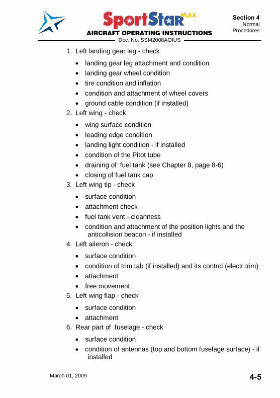
4.4 Pre-flight check Carry out pre-flight check according to the following procedure:
Figure 4-1 Scheme of airplane preflight check
WARNING CHECK BEFORE PRE-FLIGHT CHECK THAT IGNITION IS SWITCHED OFF !
NOTE The word �condition�, used in procedures of pre-flight check, means visual check of surface, damage, deformation, scratches, attrition, corrosion, icing or other effects decreasing flight safety.
AIRCRAFT OPERATING INSTRUCTIONS
Doc. No. SSM2008AOIUS
March 01, 2009 4-5
Section 4 Normal
Procedures
1. Left landing gear leg - check
landing gear leg attachment and condition
landing gear wheel condition
tire condition and inflation
condition and attachment of wheel covers
ground cable condition (if installed) 2. Left wing - check
wing surface condition
leading edge condition
landing light condition - if installed
condition of the Pitot tube
draining of fuel tank (see Chapter 8, page 8-6)
closing of fuel tank cap 3. Left wing tip - check
surface condition
attachment check
fuel tank vent - cleanness
condition and attachment of the position lights and the anticollision beacon - if installed
4. Left aileron - check
surface condition
condition of trim tab (if installed) and its control (electr.trim)
attachment
free movement 5. Left wing flap - check
surface condition
attachment 6. Rear part of fuselage - check
surface condition
condition of antennas (top and bottom fuselage surface) - if installed
AIRCRAFT OPERATING INSTRUCTIONS
Doc. No. SSM2008AOIUS
March 01, 2009 4-6
Section 4 Normal Procedures
7. Tail units - check
tail skid condition
surface condition
condition of rudder and elevator attachment
freedom of rudder and elevator movement
condition of trim tab, condition of elevator trim tab control 8. Rear part of fuselage - check
surface condition 9. Right wing flap- see 5.
10. Right aileron- see 4. except the trim tab
11. Right wing tip - see 3.
12. Right wing - see 2. except the landing light
Alternate pitot tube (IFR airplane)
AOA probe (if installed) 13. Right landing gear leg - see 1.
14. Front part of the fuselage - right hand side - check
Tip-up canopy attachment and condition
condition of the nose landing gear leg
nose wheel condition
condition of the nose wheel control rods
external power socket (if installed) 15. Engine
Checks before the first flight of day - it is necessary to remove upper engine cowling:
condition of engine bed
condition of engine attachment
condition of exhaust system
condition of engine cowlings
visual check on fuel and electrical system condition

AIRCRAFT OPERATING INSTRUCTIONS
Doc. No. SSM2008AOIUS
March 01, 2009 4-7
Section 4 Normal
Procedures
check on cooling liquid volume in the expansion tank on the engine body (replenish as required up to max. 2/3 of the expansion tank volume)
Checks before every flight:
cleanness of air intakes
check on oil level (between marks - flattenings on the dip stick)
check on cooling liquid level in the overflow bottle (volume should be approx. 0.42 pints (0.2 litre))
proper closing of the upper cowling 16. Propeller - check
attachment condition of blades, hub and spinner
17. Front part of fuselage - left hand side - check tip-up canopy attachment and condition
18. Cockpit - check NOTE
Canopy is unlocked if a latch next to lock is visible under the glass, otherwise it is locked. Unlock it first with key.
Master switch switched on Check canopy OPEN/CLOSE indication light (or a
message on the EFIS display) function all switches OFF instrument equipment check on condition check of safety belts condition and attachment check on presence of loose object in the cockpit check on adjusting and securing the rudder pedals (see
section 7.3.3) - if installed adjustable rudder pedals WARNING
RIGHT AND LEFT PEDAL OF RUDDER CONTROL MUST BE SET TO THE SAME POSITIONS AND WELL SECURED! AOI and other required documents check on completness and validity

AIRCRAFT OPERATING INSTRUCTIONS
Doc. No. SSM2008AOIUS
March 01, 2009 4-8
Section 4 Normal Procedures
4.5 Normal procedures and checklist
4.5.1 Before engine starting 1. Pre-flight check and check on
weight and centre of gravity position done
2. External power source connect as (if socket is installed) necessary
3. Safety harnesses check, fasten
4. Control stick free
5. Rudder pedals free
6. Wing flaps function check
7. Trim tab function check
8. PARKING BRAKE handle (if installed) release brakes
9. Brakes function check
10. AVIONICS SWITCH check OFF
11. Ignition check OFF
12. Canopy close
4.5.2 Engine starting 1. Master switch ON
2. Fuel gauge indicators check of fuel qty.
3. FUEL SELECTOR LEFT Pull the safety button on the fuel selector, turn the handle to the left and then release safety button. Now the handle can be freely moved between left and right position. Safety button prevents unintentionally switch the selector to OFF position.
4. Electric fuel pump (if installed) ON
5. THROTTLE lever idle
6. Choke as necessary (open by pulling up and lock by turning)
7. Space in the propeller area free

AIRCRAFT OPERATING INSTRUCTIONS
Doc. No. SSM2008AOIUS
March 01, 2009 4-9
Section 4 Normal
Procedures
8. BEACON (if installed) ON (if necessary)
9. Brakes apply
10. Ignition START (see CAUTION) after starting up BOTH
CAUTION ACTIVATE STARTER FOR 10 SEC. AS A MAXIMUM, THEN LET IT COOL DOWN FOR 2 MINUTES.
AFTER STARTING UP ENGINE, DO NOT CARRY OUT SUDDEN RPM CHANGES, AFTER POWER DECREASE WAIT FOR ABOUT 3 S IN ORDER TO REACH CONSTANT RPM BEFORE REACCELERATION.
11. THROTTLE lever as necessary (see NOTE)
12. Oil pressure up to 10s min. pressure
13. GEN, AUX GEN (if inst.) switches ON
NOTE After starting up engine, adjust throttle for smooth engine running at about 2500 RPM. Check oil pressure. Pressure must increase within 10 s. Increase engine RPM until oil pressure is stabilised over 2 bar (29 PSI).
14. Engine instruments check
15. Choke as necessary
16. Engine warming up see NOTE
NOTE Begin warming up with engine running at 2000 RPM. for about 2 minutes, continue at 2500 RPM. Warming time depends on outside air temperature until oil temperature reaches 122 °F.
17. FUEL SELECTOR RIGHT Verify proper engine feeding from the right tank for approx. 1 minute.
18. FUEL SELECTOR LEFT
AIRCRAFT OPERATING INSTRUCTIONS
Doc. No. SSM2008AOIUS
March 01, 2009 4-10
Section 4 Normal Procedures
NOTE Start engine with the fuel selector set to to LEFT. If you would start the engine with the fuel selector set to RIGHT and the left tank is full, than fuel bleed from the left tank vent may occur (and pollute environment) because a fuel return hose is led only into the left tank and returning fuel will overfill the left tank.
19. External power source if used, (if socket is installed) give instruction to disconnect it
20. AVIONICS SWITCH ON
21. Radiostation/avionics ON
22. Other electrical equipment ON as necessary
4.5.3 Before taxiing 1. Transponder (if installed) SBY 2. Outside lights (if installed) as necessary
4.5.4 Taxiing 1. THROTTLE lever as necessary
2. Brakes check by depressing
3. Rudder pedals function check
4. Direction of taxiing control by rudder pedals (these are mechanically connected with nose wheel control), possibly by slacking up left and right wheel of the main landing gear.
AIRCRAFT OPERATING INSTRUCTIONS
Doc. No. SSM2008AOIUS
March 01, 2009 4-11
Section 4 Normal
Procedures
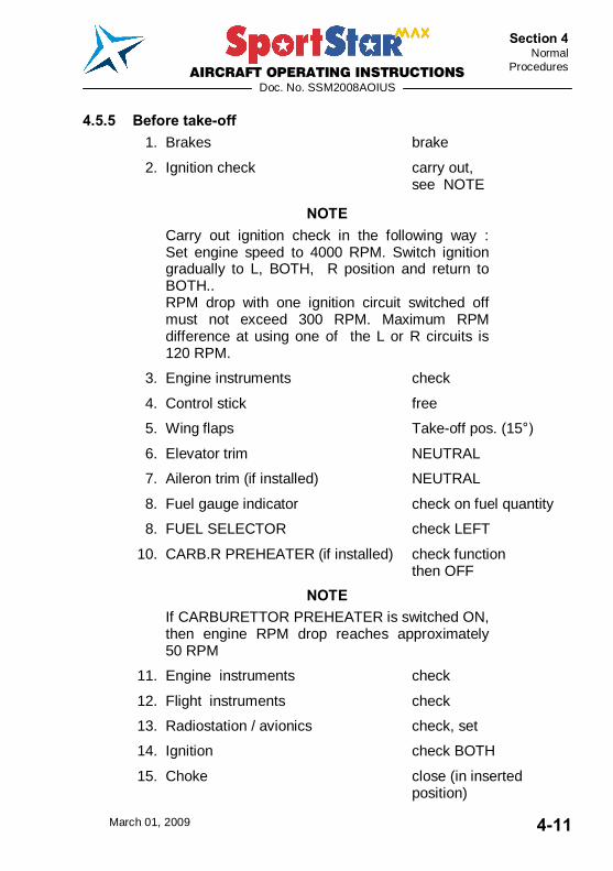
4.5.5 Before take-off 1. Brakes brake
2. Ignition check carry out, see NOTE
NOTE Carry out ignition check in the following way : Set engine speed to 4000 RPM. Switch ignition gradually to L, BOTH, R position and return to BOTH.. RPM drop with one ignition circuit switched off must not exceed 300 RPM. Maximum RPM difference at using one of the L or R circuits is 120 RPM.
3. Engine instruments check
4. Control stick free
5. Wing flaps Take-off pos. (15°)
6. Elevator trim NEUTRAL
7. Aileron trim (if installed) NEUTRAL
8. Fuel gauge indicator check on fuel quantity
8. FUEL SELECTOR check LEFT 10. CARB.R PREHEATER (if installed) check function
then OFF
NOTE If CARBURETTOR PREHEATER is switched ON, then engine RPM drop reaches approximately 50 RPM
11. Engine instruments check
12. Flight instruments check
13. Radiostation / avionics check, set
14. Ignition check BOTH
15. Choke close (in inserted position)
AIRCRAFT OPERATING INSTRUCTIONS
Doc. No. SSM2008AOIUS
March 01, 2009 4-12
Section 4 Normal Procedures
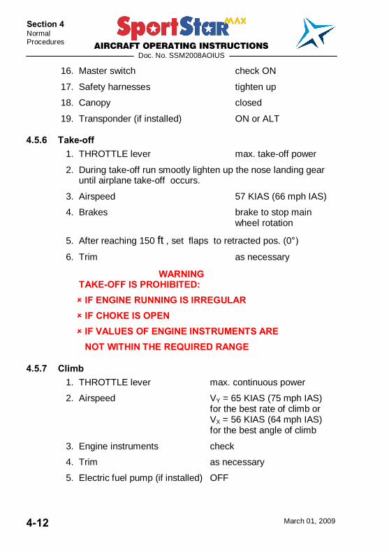
16. Master switch check ON
17. Safety harnesses tighten up
18. Canopy closed
19. Transponder (if installed) ON or ALT
4.5.6 Take-off 1. THROTTLE lever max. take-off power
2. During take-off run smootly lighten up the nose landing gear until airplane take-off occurs.
3. Airspeed 57 KIAS (66 mph IAS)
4. Brakes brake to stop main wheel rotation
5. After reaching 150 ft , set flaps to retracted pos. (0°)
6. Trim as necessary
WARNING TAKE-OFF IS PROHIBITED: IF ENGINE RUNNING IS IRREGULAR IF CHOKE IS OPEN IF VALUES OF ENGINE INSTRUMENTS ARE
NOT WITHIN THE REQUIRED RANGE
4.5.7 Climb 1. THROTTLE lever max. continuous power
2. Airspeed VY = 65 KIAS (75 mph IAS) for the best rate of climb or VX = 56 KIAS (64 mph IAS) for the best angle of climb
3. Engine instruments check
4. Trim as necessary
5. Electric fuel pump (if installed) OFF
AIRCRAFT OPERATING INSTRUCTIONS
Doc. No. SSM2008AOIUS
March 01, 2009 4-13
Section 4 Normal
Procedures
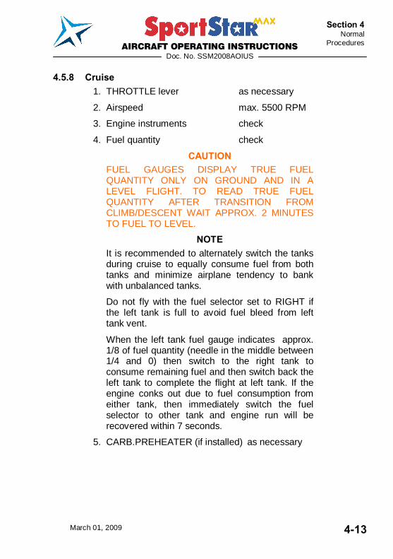
4.5.8 Cruise 1. THROTTLE lever as necessary
2. Airspeed max. 5500 RPM
3. Engine instruments check
4. Fuel quantity check
CAUTION FUEL GAUGES DISPLAY TRUE FUEL QUANTITY ONLY ON GROUND AND IN A LEVEL FLIGHT. TO READ TRUE FUEL QUANTITY AFTER TRANSITION FROM CLIMB/DESCENT WAIT APPROX. 2 MINUTES TO FUEL TO LEVEL.
NOTE It is recommended to alternately switch the tanks during cruise to equally consume fuel from both tanks and minimize airplane tendency to bank with unbalanced tanks.
Do not fly with the fuel selector set to RIGHT if the left tank is full to avoid fuel bleed from left tank vent.
When the left tank fuel gauge indicates approx. 1/8 of fuel quantity (needle in the middle between 1/4 and 0) then switch to the right tank to consume remaining fuel and then switch back the left tank to complete the flight at left tank. If the engine conks out due to fuel consumption from either tank, then immediately switch the fuel selector to other tank and engine run will be recovered within 7 seconds.
5. CARB.PREHEATER (if installed) as necessary
AIRCRAFT OPERATING INSTRUCTIONS
Doc. No. SSM2008AOIUS
March 01, 2009 4-14
Section 4 Normal Procedures
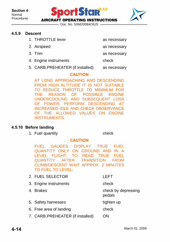
4.5.9 Descent 1. THROTTLE lever as necessary
2. Airspeed as necessary
3. Trim as necessary
4. Engine instruments check
5. CARB.PREHEATER (if installed) as necessary
CAUTION AT LONG APPROACHING AND DESCENDING FROM HIGH ALTITUDE IT IS NOT SUITABLE TO REDUCE THROTTLE TO MINIMUM FOR THE REASON OF POSSIBLE ENGINE UNDERCOOLING AND SUBSEQUENT LOSS OF POWER. PERFORM DESCENDING AT INCREASED IDLE AND CHECK OBSERVANCE OF THE ALLOWED VALUES ON ENGINE INSTRUMENTS.
4.5.10 Before landing 1. Fuel quantity check
CAUTION FUEL GAUGES DISPLAY TRUE FUEL QUANTITY ONLY ON GROUND AND IN A LEVEL FLIGHT. TO READ TRUE FUEL QUANTITY AFTER TRANSITION FROM CLIMB/DESCENT WAIT APPROX. 2 MINUTES TO FUEL TO LEVEL.
2. FUEL SELECTOR LEFT 3. Engine instruments check
4. Brakes check by depressing pedals
5. Safety harnesses tighten up
6. Free area of landing check
7. CARB.PREHEATER (if installed) ON
AIRCRAFT OPERATING INSTRUCTIONS
Doc. No. SSM2008AOIUS
March 01, 2009 4-15
Section 4 Normal
Procedures
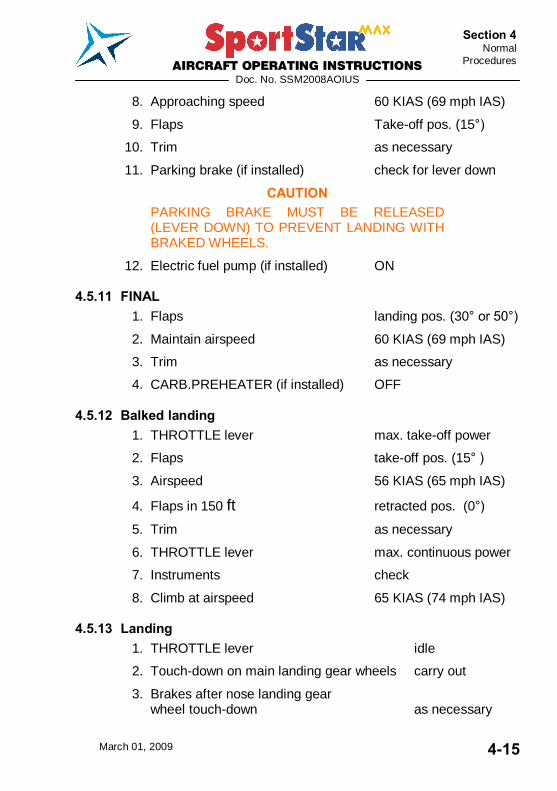
8. Approaching speed 60 KIAS (69 mph IAS)
9. Flaps Take-off pos. (15°)
10. Trim as necessary
11. Parking brake (if installed) check for lever down
CAUTION PARKING BRAKE MUST BE RELEASED (LEVER DOWN) TO PREVENT LANDING WITH BRAKED WHEELS.
12. Electric fuel pump (if installed) ON
4.5.11 FINAL 1. Flaps landing pos. (30° or 50°)
2. Maintain airspeed 60 KIAS (69 mph IAS)
3. Trim as necessary
4. CARB.PREHEATER (if installed) OFF
4.5.12 Balked landing 1. THROTTLE lever max. take-off power
2. Flaps take-off pos. (15° )
3. Airspeed 56 KIAS (65 mph IAS)
4. Flaps in 150 ft retracted pos. (0°)
5. Trim as necessary
6. THROTTLE lever max. continuous power
7. Instruments check
8. Climb at airspeed 65 KIAS (74 mph IAS)
4.5.13 Landing 1. THROTTLE lever idle
2. Touch-down on main landing gear wheels carry out
3. Brakes after nose landing gear wheel touch-down as necessary
AIRCRAFT OPERATING INSTRUCTIONS
Doc. No. SSM2008AOIUS
March 01, 2009 4-16
Section 4 Normal Procedures
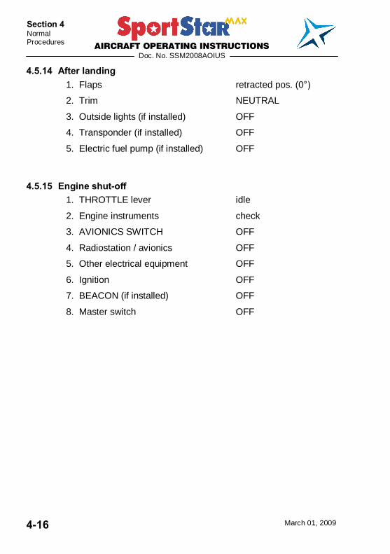
4.5.14 After landing 1. Flaps retracted pos. (0°)
2. Trim NEUTRAL
3. Outside lights (if installed) OFF
4. Transponder (if installed) OFF
5. Electric fuel pump (if installed) OFF
4.5.15 Engine shut-off 1. THROTTLE lever idle
2. Engine instruments check
3. AVIONICS SWITCH OFF
4. Radiostation / avionics OFF
5. Other electrical equipment OFF
6. Ignition OFF
7. BEACON (if installed) OFF
8. Master switch OFF
AIRCRAFT OPERATING INSTRUCTIONS
Doc. No. SSM2008AOIUS
March 01, 2009 4-17
Section 4 Normal
Procedures
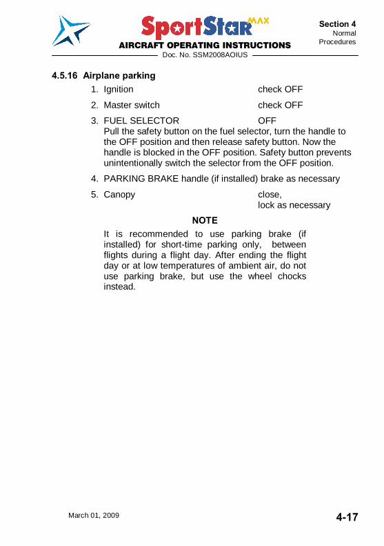
4.5.16 Airplane parking 1. Ignition check OFF
2. Master switch check OFF
3. FUEL SELECTOR OFF Pull the safety button on the fuel selector, turn the handle to the OFF position and then release safety button. Now the handle is blocked in the OFF position. Safety button prevents unintentionally switch the selector from the OFF position.
4. PARKING BRAKE handle (if installed) brake as necessary
5. Canopy close, lock as necessary
NOTE It is recommended to use parking brake (if installed) for short-time parking only, between flights during a flight day. After ending the flight day or at low temperatures of ambient air, do not use parking brake, but use the wheel chocks instead.

AIRCRAFT OPERATING INSTRUCTIONS
Doc. No. SSM2008AOIUS
March 01, 2009 4-18
Section 4 Normal Procedures
Intentionally left blank
AIRCRAFT OPERATING INSTRUCTIONS
Doc. No. SSM2008AOIUS
March 01, 2009 5-1
Section 5 Performance
SECTION 5
5. PERFORMANCE 5.1 Introduction ....................................................................5-3
5.2 Approved data................................................................5-4 5.2.1 Airspeed indicator system calibration................................. 5-4 5.2.2 Stall speeds ...................................................................... 5-6 5.2.3 Take-off distance .............................................................. 5-7 5.2.4 Landing distance............................................................... 5-7 5.2.5 Climb performance............................................................ 5-8
5.3 Additional information .................................................5-10 5.3.1 Cruise ............................................................................. 5-10 5.3.2 Horizontal speeds ........................................................... 5-11 5.3.3 Endurance ...................................................................... 5-12 5.3.4 Balked landing climb ....................................................... 5-13 5.3.5 Effect on flight performance and characteristics............... 5-14 5.3.6 Demonstrated crosswind performance ............................ 5-14 5.3.7 Ceiling ............................................................................ 5-15 5.3.8 Noise data ...................................................................... 5-15
AIRCRAFT OPERATING INSTRUCTIONS
Doc. No. SSM2008AOIUS
March 01, 2009 5-2
Section 5 Performance
Intentionally left blank
AIRCRAFT OPERATING INSTRUCTIONS
Doc. No. SSM2008AOIUS
March 01, 2009 5-3
Section 5 Performance
5.1 Introduction Section 5 provides data for airspeed calibration, stall speeds, take-off performance and additional information, provided by the airplane manufacturer.
The stated performance data has been computed from actual flight tests with the airplane and engine in good condition and using average piloting techniques.
CAUTION THE PERFORMANCE STATED IN THIS SECTION IS VALID FOR STANDARD POWERPLANT - ROTAX 912 ULS (100 HP) TOGETHER WITH WOODCOMP KLASSIC 170/3/R PROPELLER INSTALLED IN THE AIRPLANE.
FOR ACTUAL PERFORMANCE SEE SECTION 9 - SUPPLEMENTS.
AIRCRAFT OPERATING INSTRUCTIONS
Doc. No. SSM2008AOIUS
March 01, 2009 5-4
Section 5 Performance
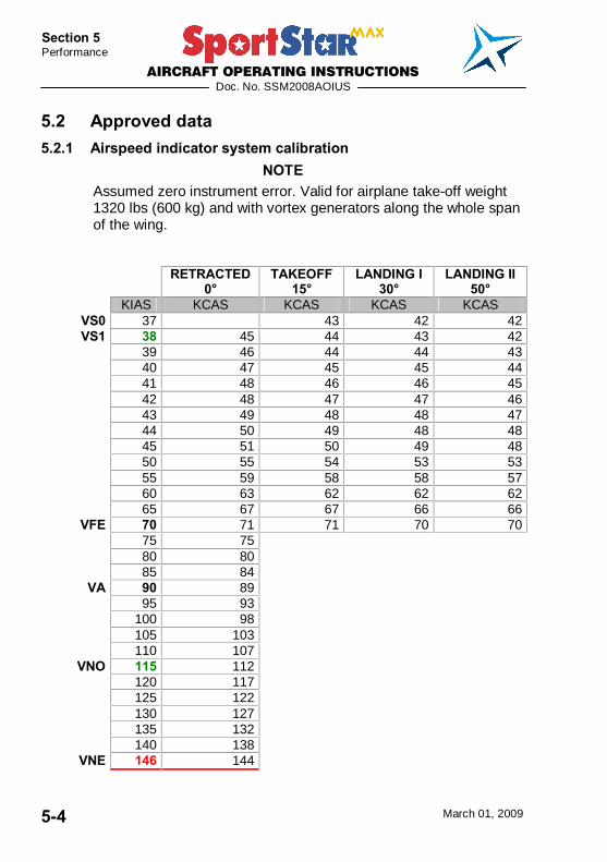
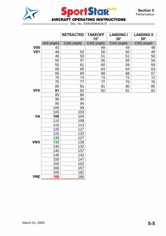
5.2 Approved data 5.2.1 Airspeed indicator system calibration
NOTE Assumed zero instrument error. Valid for airplane take-off weight 1320 lbs (600 kg) and with vortex generators along the whole span of the wing.
RETRACTED
0° TAKEOFF
15° LANDING I
30° LANDING II
50° KIAS KCAS KCAS KCAS KCAS
VS0 37 43 42 42 VS1 38 45 44 43 42
39 46 44 44 43 40 47 45 45 44 41 48 46 46 45 42 48 47 47 46
43 49 48 48 47 44 50 49 48 48 45 51 50 49 48 50 55 54 53 53 55 59 58 58 57 60 63 62 62 62 65 67 67 66 66
VFE 70 71 71 70 70 75 75 80 80 85 84
VA 90 89 95 93 100 98
105 103 110 107
VNO 115 112 120 117 125 122 130 127 135 132 140 138
VNE 146 144
AIRCRAFT OPERATING INSTRUCTIONS
Doc. No. SSM2008AOIUS
March 01, 2009 5-5
Section 5 Performance
RETRACTED TAKEOFF
15° LANDING I
30° LANDING II
50° IAS (mph) CAS (mph) CAS (mph) CAS (mph) CAS (mph)
VS0 43 49 49 48 VS1 44 52 50 50 49
45 53 51 51 50 50 57 56 55 54 55 61 60 59 59 60 65 64 64 63
65 69 68 68 67 70 73 73 72 72 75 77 77 76 76 80 81 81 80 80
VFE 81 82 82 81 81 85 86 90 90 95 94 100 99 105 103
VA 106 104 110 108
115 113 120 117
125 122 130 127
VNO 132 129 135 132 140 137 145 142 150 147 155 152 160 157 165 162
VNE 168 166
AIRCRAFT OPERATING INSTRUCTIONS
Doc. No. SSM2008AOIUS
March 01, 2009 5-6
Section 5 Performance
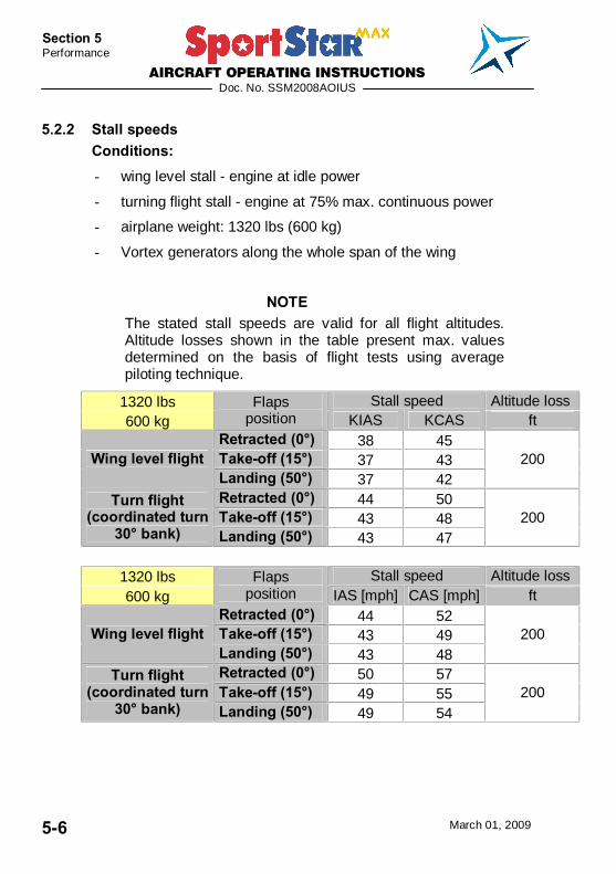
5.2.2 Stall speeds Conditions: - wing level stall - engine at idle power
- turning flight stall - engine at 75% max. continuous power
- airplane weight: 1320 lbs (600 kg)
- Vortex generators along the whole span of the wing
NOTE The stated stall speeds are valid for all flight altitudes. Altitude losses shown in the table present max. values determined on the basis of flight tests using average piloting technique.
1320 lbs Stall speed Altitude loss 600 kg
Flaps position KIAS KCAS ft
Retracted (0°) 38 45 Take-off (15°) 37 43 Wing level flight Landing (50°) 37 42
200
Retracted (0°) 44 50 Take-off (15°) 43 48
Turn flight (coordinated turn
30° bank) Landing (50°) 43 47 200
1320 lbs Stall speed Altitude loss 600 kg
Flaps position IAS [mph] CAS [mph] ft
Retracted (0°) 44 52 Take-off (15°) 43 49 Wing level flight Landing (50°) 43 48
200
Retracted (0°) 50 57 Take-off (15°) 49 55
Turn flight (coordinated turn
30° bank) Landing (50°) 49 54 200

AIRCRAFT OPERATING INSTRUCTIONS
Doc. No. SSM2008AOIUS
March 01, 2009 5-7
Section 5 Performance
5.2.3 Take-off distance Conditions: - engine: max. take-off power - flaps: Take-off (15°) - carburetter preheating: OFF - airplane weight: 1268 lbs - altitude: 0 ft ISA - ambient air temperature: ISA
Take-off run Take-off distance to height of 50 ft (15 ft)
Dray concrete 620 ft 1440 ft Grass 720 ft 1540 ft
Corrections: - Influence of wind: Add 4% on every 1 kt (1.15 mph) of tail wind - RWY inclination: Add 8% of the take-off run distance on 1% of ruway inclination up the slope
5.2.4 Landing distance Conditions: - engine: idle - flaps: Landing 50° - carburetter preheating: OFF - airplane weight: 1268 lbs - altitude: 0 ft ISA - ambient air temperature: ISA
Landing distance from height of
50 ft (15 ft)
Braked landing run
Dray concrete 1310 ft 590 ft Grass 1250 ft 520 ft
Corrections: - Influence of wind: Add 4.5 % on every 1 kt (1.15 mph) of tail wind - RWY inclination: Add 8% of the landing run distance on 1% of ruway inclination down the slope
AIRCRAFT OPERATING INSTRUCTIONS
Doc. No. SSM2008AOIUS
March 01, 2009 5-8
Section 5 Performance
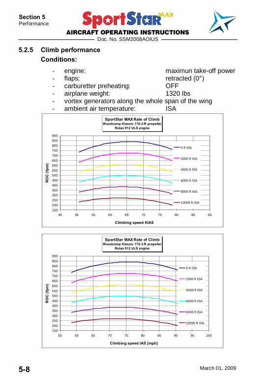
5.2.5 Climb performance Conditions:
- engine: maximun take-off power - flaps: retracted (0°) - carburetter preheating: OFF - airplane weight: 1320 lbs - vortex generators along the whole span of the wing - ambient air temperature: ISA
SportStar MAX Rate of ClimbWoodcomp Klassic 170-3-R propeller
Rotax 912 ULS engine
150
200
250
300
350
400
450
500
550
600
650
700
750
800
850
900
45 50 55 60 65 70 75 80 85 90
Climbing speed KIAS
RO
C (f
pm)
0 ft ISA
2000 ft ISA
4000 ft ISA
6000 ft ISA
8000 ft ISA
10000 ft ISA
SportStar MAX Rate of ClimbWoodcomp Klassic 170-3-R propeller
Rotax 912 ULS engine
150
200
250
300
350
400
450
500
550
600
650
700
750
800
850
900
55 60 65 70 75 80 85 90 95 100
Climbing speed IAS [mph]
RO
C (f
pm)
0 ft ISA
2000 ft ISA
4000 ft ISA
6000 ft ISA
8000 ft ISA
10000 ft ISA
AIRCRAFT OPERATING INSTRUCTIONS
Doc. No. SSM2008AOIUS
March 01, 2009 5-9
Section 5 Performance
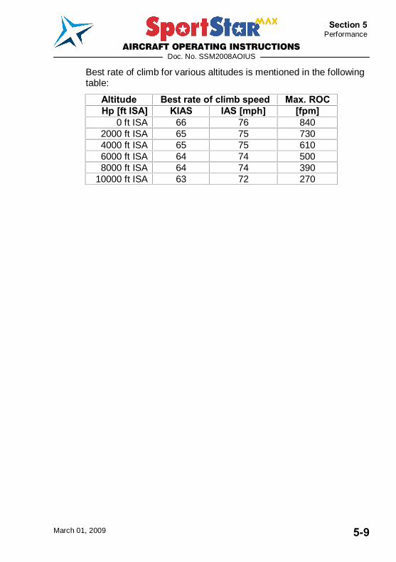
Best rate of climb for various altitudes is mentioned in the following table:
Altitude Best rate of climb speed Max. ROC Hp [ft ISA] KIAS IAS [mph] [fpm]
0 ft ISA 66 76 840 2000 ft ISA 65 75 730 4000 ft ISA 65 75 610 6000 ft ISA 64 74 500 8000 ft ISA 64 74 390
10000 ft ISA 63 72 270

AIRCRAFT OPERATING INSTRUCTIONS
Doc. No. SSM2008AOIUS
March 01, 2009 5-10
Section 5 Performance
5.3 Additional information
5.3.1 Cruise Conditions:
- flaps: retracted (0°) - carburetter preheating: OFF - airplane weight: 1320 lbs (600 kg) - vortex generators along the whole span of the wing - ambient air temperature: ISA
SportStar MAX HORIZONTAL SPEEDS Rotax 912 ULS, Woodcomp Klassic 170/3/R
Vortex Generators on the wing
40 KCAS
45 KCAS
50 KCAS
55 KCAS
60 KCAS
65 KCAS
70 KCAS
75 KCAS
80 KCAS
85 KCAS
90 KCAS
95 KCAS
100 KCAS
105 KCAS
110 KCAS
115 KCAS
120 KCAS
3500
rpm
3600
rpm
3700
rpm
3800
rpm
3900
rpm
4000
rpm
4100
rpm
4200
rpm
4300
rpm
4400
rpm
4500
rpm
4600
rpm
4700
rpm
4800
rpm
4900
rpm
5000
rpm
5100
rpm
5200
rpm
5300
rpm
5400
rpm
5500
rpm
5600
rpm
5700
rpm
5800
rpm
0 ft ISA
2000 ft ISA
4000 ft ISA
6000 ft ISA
8000 ft ISA
10000 ft ISA
SportStar MAX HORIZONTAL SPEEDS Rotax 912 ULS, Woodcomp Klassic 170/3/R
Vortex Generators on the w ing
40 mph CAS
45 mph CAS
50 mph CAS
55 mph CAS
60 mph CAS
65 mph CAS
70 mph CAS
75 mph CAS
80 mph CAS
85 mph CAS
90 mph CAS
95 mph CAS
100 mph CAS
105 mph CAS
110 mph CAS
115 mph CAS
120 mph CAS
3500
rpm
3600
rpm
3700
rpm
3800
rpm
3900
rpm
4000
rpm
4100
rpm
4200
rpm
4300
rpm
4400
rpm
4500
rpm
4600
rpm
4700
rpm
4800
rpm
4900
rpm
5000
rpm
5100
rpm
5200
rpm
5300
rpm
5400
rpm
5500
rpm
5600
rpm
5700
rpm
5800
rpm
0 ft ISA
2000 ft ISA
4000 ft ISA
6000 ft ISA
8000 ft ISA
10000 ft ISA
AIRCRAFT OPERATING INSTRUCTIONS
Doc. No. SSM2008AOIUS
March 01, 2009 5-11
Section 5 Performance
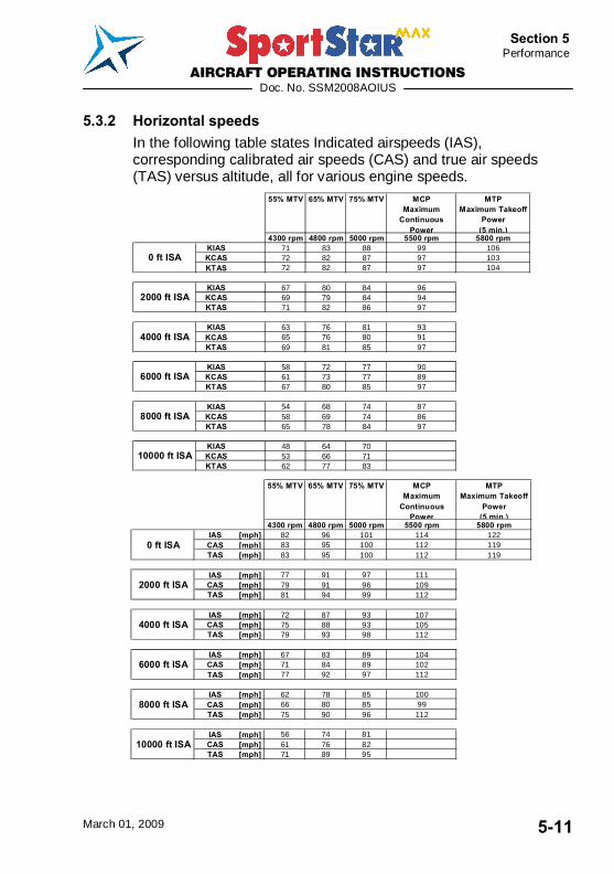
5.3.2 Horizontal speeds In the following table states Indicated airspeeds (IAS), corresponding calibrated air speeds (CAS) and true air speeds (TAS) versus altitude, all for various engine speeds.
55% MTV 65% MTV 75% MTV MCPMaximum
Continuous Power
MTPMaximum Takeoff
Power(5 min.)
4300 rpm 4800 rpm 5000 rpm 5500 rpm 5800 rpmKIAS 71 83 88 99 106KCAS 72 82 87 97 103KTAS 72 82 87 97 104
KIAS 67 80 84 96KCAS 69 79 84 94KTAS 71 82 86 97
KIAS 63 76 81 93KCAS 65 76 80 91KTAS 69 81 85 97
KIAS 58 72 77 90KCAS 61 73 77 89KTAS 67 80 85 97
KIAS 54 68 74 87KCAS 58 69 74 86KTAS 65 78 84 97
KIAS 48 64 70KCAS 53 66 71KTAS 62 77 83
4000 ft ISA
6000 ft ISA
8000 ft ISA
10000 ft ISA
0 ft ISA
2000 ft ISA
55% MTV 65% MTV 75% MTV MCP
Maximum Continuous
Power
MTPMaximum Takeoff
Power(5 min.)
4300 rpm 4800 rpm 5000 rpm 5500 rpm 5800 rpmIAS [mph] 82 96 101 114 122CAS [mph] 83 95 100 112 119TAS [mph] 83 95 100 112 119
IAS [mph] 77 91 97 111CAS [mph] 79 91 96 109TAS [mph] 81 94 99 112
IAS [mph] 72 87 93 107CAS [mph] 75 88 93 105TAS [mph] 79 93 98 112
IAS [mph] 67 83 89 104CAS [mph] 71 84 89 102TAS [mph] 77 92 97 112
IAS [mph] 62 78 85 100CAS [mph] 66 80 85 99TAS [mph] 75 90 96 112
IAS [mph] 56 74 81CAS [mph] 61 76 82TAS [mph] 71 89 95
8000 ft ISA
10000 ft ISA
0 ft ISA
2000 ft ISA
4000 ft ISA
6000 ft ISA
AIRCRAFT OPERATING INSTRUCTIONS
Doc. No. SSM2008AOIUS
March 01, 2009 5-12
Section 5 Performance
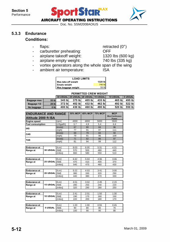
5.3.3 Endurance Conditions:
- flaps: retracted (0°) - carburetter preheating: OFF - airplane takeoff weight: 1320 lbs (600 kg) - airplane empty weight: 740 lbs (335 kg) - vortex generators along the whole span of the wing - ambient air temperature: ISA
Max.take-off weight 1320 lb Empty weight 740 lb Max.baggage weight 55 lb
30 USGAL 25 USGAL 20 USGAL 15 USGAL 10 USGAL 5 USGALBaggage max. 55 lb 345 lb 375 lb 405 lb 435 lb 465 lb 495 lbBaggage 1/2 28 lb 372 lb 402 lb 432 lb 462 lb 492 lb 522 lbNo baggage 0 lb 400 lb 430 lb 460 lb 490 lb 520 lb 550 lb
55% MCP 65% MCP 75% MCP MCPMax.Continuous
Power[rpm] 4300 4800 5000 5500[USgal/h] 3,7 4,9 5,4 6,6[knots] 67 80 84 96[mph] 77 91 97 111[knots] 69 79 84 94[mph] 79 91 96 109[knots] 71 82 86 97[mph] 81 94 99 112
Endurance at [h:m] 8:03 6:05 5:31 4:31[NM] 570 500 480 440[miles] 660 580 550 510
Endurance at [h:m] 6:42 5:04 4:36 3:46[NM] 470 410 400 370[miles] 540 470 460 430
Endurance at [h:m] 5:22 4:03 3:41 3:00[NM] 380 330 320 290[miles] 440 380 370 330
Endurance at [h:m] 4:01 3:02 2:45 2:15[NM] 280 250 240 220[miles] 320 290 280 250
Endurance at [h:m] 2:41 2:01 1:50 1:30[NM] 190 170 160 150[miles] 220 200 180 170
Endurance at [h:m] 1:20 1:00 0:55 0:45[NM] 90 80 80 70[miles] 100 90 90 80
10 USGALRange at
5 USGALRange at
Range at
Range at
IAS
CAS
TAS
30 USGAL
25 USGAL
Fuel consumption
20 USGALRange at
15 USGALRange at
PERMITTED CREW WEIGHT
ENDURANCE AND RANGEAltitude 2000 ft ISAEngine speed
LOAD LIMITS
AIRCRAFT OPERATING INSTRUCTIONS
Doc. No. SSM2008AOIUS
March 01, 2009 5-13
Section 5 Performance
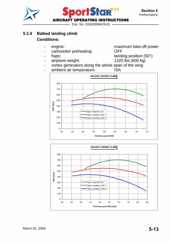
5.3.4 Balked landing climb Conditions:
- engine: maximum take-off power - carburetter preheating: OFF - flaps: landing position (50°) - airplane weight: 1320 lbs (600 kg) - vortex generators along the whole span of the wing - ambient air temperature: ISA
BALKED LANDING CLIMB
0
100
200
300
400
500
600
700
800
35 40 45 50 55 60 65 70 75
Climbing speed KIAS
RO
C [f
pm]
Flaps Takeoff (15°)Flaps Landing I (30°)Flaps Landing II (50°)
BALKED LANDING CLIMB
0
100
200
300
400
500
600
700
800
40 45 50 55 60 65 70 75 80 85
Climbing speed IAS [mph]
ROC
[fpm
]
Flaps Takeoff (15°)Flaps Landing I (30°)Flaps Landing II (50°)
AIRCRAFT OPERATING INSTRUCTIONS
Doc. No. SSM2008AOIUS
March 01, 2009 5-14
Section 5 Performance
5.3.5 Effect on flight performance and characteristics Flight performances and characteristics are not considerably affected by rain or insect stuck on the airplane surface.
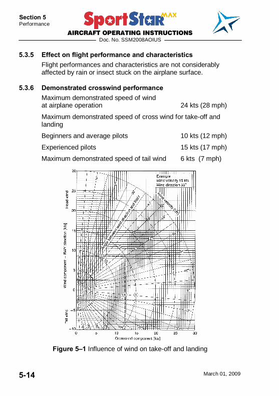
5.3.6 Demonstrated crosswind performance Maximum demonstrated speed of wind at airplane operation 24 kts (28 mph)
Maximum demonstrated speed of cross wind for take-off and landing
Beginners and average pilots 10 kts (12 mph)
Experienced pilots 15 kts (17 mph)
Maximum demonstrated speed of tail wind 6 kts (7 mph)
Figure 5�1 Influence of wind on take-off and landing

AIRCRAFT OPERATING INSTRUCTIONS
Doc. No. SSM2008AOIUS
March 01, 2009 5-15
Section 5 Performance
5.3.7 Ceiling Service ceiling (ROC 100 fpm) 13 000 ft
5.3.8 Noise data Not measured.

AIRCRAFT OPERATING INSTRUCTIONS
Doc. No. SSM2008AOIUS
March 01, 2009 5-16
Section 5 Performance
Intentionally left blank

AIRCRAFT OPERATING INSTRUCTIONS
Doc. No. SSM2008AOIUS
March 01, 2009 6-1
Section 6 Weight and
Balance
SECTION 6
6. WEIGHT AND BALANCE 6.1 Introduction ....................................................................6-3
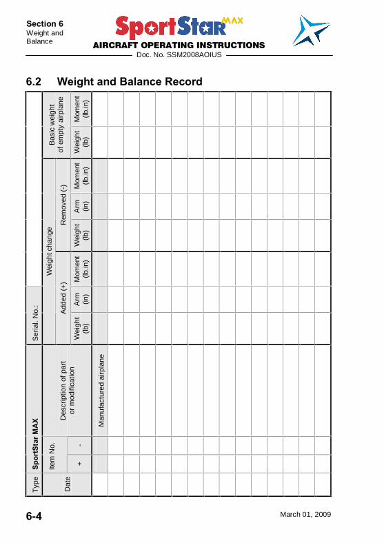
6.2 Weight and Balance Record..........................................6-4
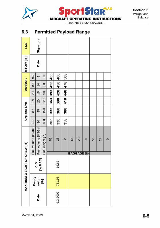
6.3 Permitted Payload Range..............................................6-5
6.4 Operational Weight and Balance Computation............6-6 6.4.1 Computational Procedure.................................................. 6-6
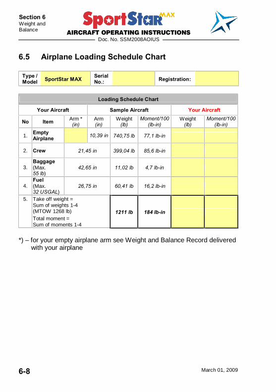
6.5 Airplane Loading Schedule Chart.................................6-8
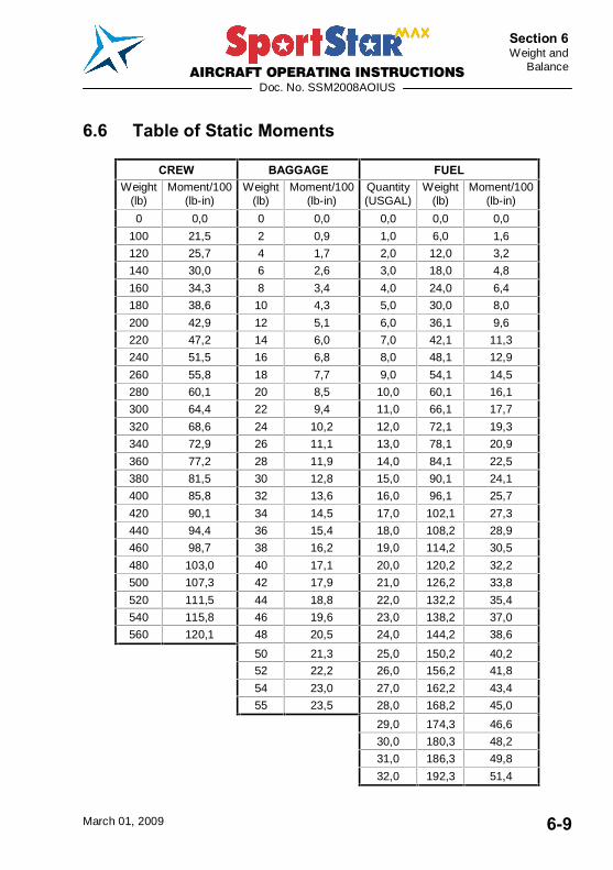
6.6 Table of Static Moments ................................................6-9
6.7 Airplane Loading Graph ..............................................6-10
6.8 CG Moment Envelope ..................................................6-11
6.9 Operational Weight and CG Envelope ........................6-12
6.10 Equipment List .............................................................6-13

AIRCRAFT OPERATING INSTRUCTIONS
Doc. No. SSM2008AOIUS
March 01, 2009 6-2
Section 6 Weight and Balance
Intentionally left blank

AIRCRAFT OPERATING INSTRUCTIONS
Doc. No. SSM2008AOIUS
March 01, 2009 6-3
Section 6 Weight and
Balance
6.1 Introduction This Section includes Weight and Balance Record of empty airplane, Permitted Payload Range within which the airplane may be safely operated, and a method to determine whether the operational weight and CG location will be within the permitted limits range. Procedure for weighing the airplane and the calculation method for establishing the permitted payload range are contained in the Aircraft Maintenance and Inspection Procedures for the SportStar MAX Light Sport Aircraft.
AIRCRAFT OPERATING INSTRUCTIONS
Doc. No. SSM2008AOIUS
March 01, 2009 6-4
Section 6 Weight and Balance
6.2 Weight and Balance Record M
omen
t (lb
.in)
Bas
ic w
eigh
t of
em
pty
airp
lane
Wei
ght
(lb)
Mom
ent
(lb.in
)
Arm
(in
)
Rem
oved
(-)
Wei
ght
(lb)
Mom
ent
(lb.in
)
Arm
(in
)
Ser
ial.
No.
:
Wei
ght c
hang
e
Add
ed (
+)
Wei
ght
(lb)
Des
crip
tion
of p
art
or m
odifi
catio
n
Man
ufac
ture
d ai
rpla
ne
-
Spor
tSta
r MA
X
Item
No.
+
Typ
e
Dat
e
AIRCRAFT OPERATING INSTRUCTIONS
Doc. No. SSM2008AOIUS
March 01, 2009 6-5
Section 6 Weight and
Balance
6.3 Permitted Payload Range 13
20M
TOW
[lb]
:
0,2 5 30 453
480
508
0,3
10 60 423
450
478
0,4
15 90 393
420
448
0,6
20 120
363
390
418
0,8
25 150
333
360
388
1,0
30 180
303
330
358
55 28 0 55 28 0 55 28 0
Fue
l vol
ume
[US
Gal
.]
MA
XIM
UM
WE
IGH
T O
F C
RE
W [l
b]A
irpl
ane
S/N
:20
0806
10
Sign
atur
eD
ate
C.G
.[%
MA
C]
Empt
yw
eigh
t[lb
]F
uel w
eigh
t [lb
]
6.3.
2009
781,
9819
,66
BAGGAGE [lb]
Dat
e
Fue
l vol
ume
gaug
e
AIRCRAFT OPERATING INSTRUCTIONS
Doc. No. SSM2008AOIUS
March 01, 2009 6-6
Section 6 Weight and Balance
6.4 Operational Weight and Balance Computation An important part of preflight planning is to determine that the aircraft is loaded so its weight and CG location are within the allowable limits. This is possible by using hereafter explained Loading graph method, using weights, arms, and moment indexes.
6.4.1 Computational Procedure 1. Record into the Airplane Loading Schedule Chart current
empty weight and static moment of the airplane, which you read from the table 6.2 Weight and Balance Record.
2. Record the weight of crew, fuel, and baggage into the Airplane Loading Schedule Chart.
3. See the Table of Static Moments or Airplane Loading Graph to read static moments for given weights of crew, fuel, and baggage
4. Record found moments into the Airplane Loading Schedule Chart
5. Determine Take-off weight of the airplane � add together the airplane empty weight, crew, fuel, and baggage and record the result into the Loading Schedule Chart.
6. Check, whether the calculated Take-off weight does not exceed Airplane Maximum Take-off Weight 1320 lb. If yes, then it is necessary to reduce weight of some of the useful load items (fuel, baggage).
WARNING EXCEEDING MTOW MAY LEAD TO
DETERIORATION OF SAFETY OF FLIGHT!
7. Determine Total Static Moment of loaded airplane � add together the static moment of empty airplane, crew, fuel, and baggage and record the result into the Loading Schedule Chart.
8. Plot Takeoff Weight and Total Static Moment into the SportStar MAX CG Moment Envelope.
9. Check, whether the intersection of Take-off weight horizontal line and Total Static Moment vertical line is inside the envelope. If YES, then the flight may be safely performed as regards weight and balance. If NOT, then it is necessary to change weight of some of the
AIRCRAFT OPERATING INSTRUCTIONS
Doc. No. SSM2008AOIUS
March 01, 2009 6-7
Section 6 Weight and
Balance
useful load items (crew, fuel, baggage) so that after a repeated computation the intersection of Take-off Weight and Total Static Moment will be inside the CG Moment envelope.
WARNING SAFETY OF FLIGHT PERFORMED WITH THE AIRPLANE LOADED OUTSIDE PERMITTED LIMITS OF WEIGHT AND STATIC MOMENTS MAY BE DETERIORATED!
AIRCRAFT OPERATING INSTRUCTIONS
Doc. No. SSM2008AOIUS
March 01, 2009 6-8
Section 6 Weight and Balance
6.5 Airplane Loading Schedule Chart
Type / Model SportStar MAX Serial
No.: Registration:
Loading Schedule Chart
Your Aircraft Sample Aircraft Your Aircraft
No Item Arm * (in)
Arm (in)
Weight (lb)
Moment/100 (lb-in)
Weight (lb)
Moment/100 (lb-in)
1. Empty Airplane 10,39 in 740,75 lb 77,1 lb-in
2. Crew 21,45 in 399,04 lb 85,6 lb-in
3. Baggage (Max. 55 lb)
42,65 in 11,02 lb 4,7 lb-in
4. Fuel (Max. 32 USGAL)
26,75 in 60,41 lb 16,2 lb-in
5. Take off weight = Sum of weights 1-4 (MTOW 1268 lb) Total moment = Sum of moments 1-4
1211 lb 184 lb-in
*) � for your empty airplane arm see Weight and Balance Record delivered
with your airplane
AIRCRAFT OPERATING INSTRUCTIONS
Doc. No. SSM2008AOIUS
March 01, 2009 6-9
Section 6 Weight and
Balance
6.6 Table of Static Moments
CREW BAGGAGE FUEL Weight
(lb) Moment/100
(lb-in) Weight
(lb) Moment/100
(lb-in) Quantity (USGAL)
Weight (lb)
Moment/100 (lb-in)
0 0,0 0 0,0 0,0 0,0 0,0
100 21,5 2 0,9 1,0 6,0 1,6
120 25,7 4 1,7 2,0 12,0 3,2
140 30,0 6 2,6 3,0 18,0 4,8
160 34,3 8 3,4 4,0 24,0 6,4
180 38,6 10 4,3 5,0 30,0 8,0
200 42,9 12 5,1 6,0 36,1 9,6
220 47,2 14 6,0 7,0 42,1 11,3
240 51,5 16 6,8 8,0 48,1 12,9
260 55,8 18 7,7 9,0 54,1 14,5
280 60,1 20 8,5 10,0 60,1 16,1
300 64,4 22 9,4 11,0 66,1 17,7
320 68,6 24 10,2 12,0 72,1 19,3
340 72,9 26 11,1 13,0 78,1 20,9
360 77,2 28 11,9 14,0 84,1 22,5
380 81,5 30 12,8 15,0 90,1 24,1
400 85,8 32 13,6 16,0 96,1 25,7
420 90,1 34 14,5 17,0 102,1 27,3
440 94,4 36 15,4 18,0 108,2 28,9
460 98,7 38 16,2 19,0 114,2 30,5
480 103,0 40 17,1 20,0 120,2 32,2
500 107,3 42 17,9 21,0 126,2 33,8
520 111,5 44 18,8 22,0 132,2 35,4
540 115,8 46 19,6 23,0 138,2 37,0
560 120,1 48 20,5 24,0 144,2 38,6
50 21,3 25,0 150,2 40,2
52 22,2 26,0 156,2 41,8
54 23,0 27,0 162,2 43,4
55 23,5 28,0 168,2 45,0
29,0 174,3 46,6
30,0 180,3 48,2
31,0 186,3 49,8
32,0 192,3 51,4
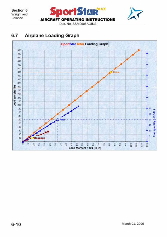
AIRCRAFT OPERATING INSTRUCTIONS
Doc. No. SSM2008AOIUS
March 01, 2009 6-10
Section 6 Weight and Balance
6.7 Airplane Loading Graph SportStar MAX Loading Graph
Crew
Baggage
Fuel
0
20
40
60
80
100
120
140
160
180
200
220
240
260
280
300
320
340
360
380
400
420
440
460
480
500
0 5 10 15 20 25 30 35 40 45 50 55 60 65 70 75 80 85 90 95 100
105
110
115
Load Moment / 100 (lb-in)
Load
Wei
ght (
lb)
0
5
10
15
20
25
30
35
40
45
50
55
60
65
70
75
80
Fuel
qua
ntity
(USG
AL)
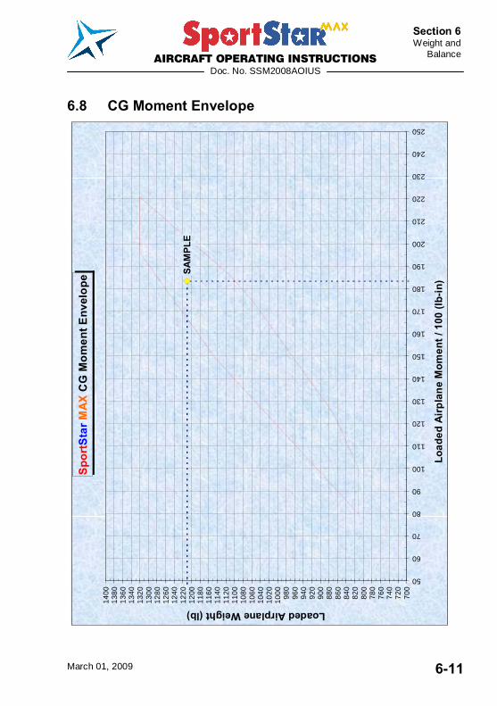
AIRCRAFT OPERATING INSTRUCTIONS
Doc. No. SSM2008AOIUS
March 01, 2009 6-11
Section 6 Weight and
Balance
6.8 CG Moment Envelope
Spo
rtS
tar M
AX
CG
Mom
ent E
nvel
ope SA
MPL
E
700
720
740
760
780
800
820
840
860
880
900
920
940
960
980
1000
1020
1040
1060
1080
1100
1120
1140
1160
1180
1200
1220
1240
1260
1280
1300
1320
1340
1360
1380
1400
50
60
70
80
90
100
110
120
130
140
150
160
170
180
190
200
210
220
230
240
250
Load
ed A
irpl
ane
Mom
ent /
100
(lb-
in)
Loaded Airplane Weight (lb)
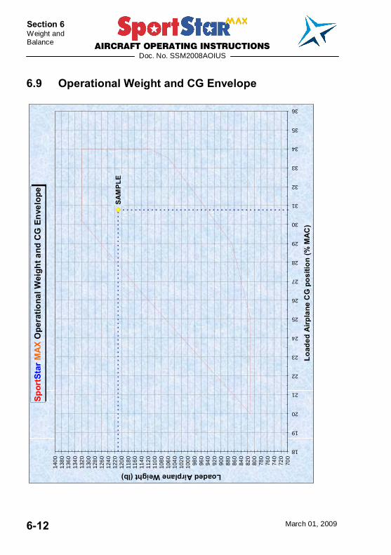
AIRCRAFT OPERATING INSTRUCTIONS
Doc. No. SSM2008AOIUS
March 01, 2009 6-12
Section 6 Weight and Balance
6.9 Operational Weight and CG Envelope
Spor
tSta
r MAX
Ope
ratio
nal W
eigh
t and
CG
Env
elop
e
SAM
PLE
700
720
740
760
780
800
820
840
860
880
900
920
940
960
980
100
010
20
104
010
60
108
011
00
112
011
40
116
011
80
120
012
20
124
012
60
128
013
00
132
013
40
136
013
80
140
0
18
19
20
21
22
23
24
25
26
27
28
29
30
31
32
33
34
35
36
Load
ed A
irpla
ne C
G p
ositi
on (%
MA
C)
Loaded Airplane Weight (lb)
AIRCRAFT OPERATING INSTRUCTIONS
Doc. No. SSM2008AOIUS
March 01, 2009 6-13
Section 6 Weight and
Balance
6.10 Equipment List The equipment installed in the airplane of particular serial number is shown in the following Equipment list.
Airplane Serial No.:
Registration Date:
Description Type Part No. Manufacturer Installed
AIRCRAFT OPERATING INSTRUCTIONS
Doc. No. SSM2008AOIUS
March 01, 2009 6-14
Section 6 Weight and Balance
Airplane Serial No.:
Registration Date:
Description Type Part No. Manufacturer Installed

AIRCRAFT OPERATING INSTRUCTIONS
Doc. No. SSM2008AOIUS
March 01, 2009 7-1
Section 7 Airplane and System
Description
SECTION 7
7. AIRPLANE AND SYSTEM DESCRIPTION 7.1 Introduction ....................................................................7-3
7.2 Airframe ..........................................................................7-3 7.2.1 Fuselage........................................................................... 7-3 7.2.2 Wing ................................................................................. 7-3 7.2.3 Horizontal tail unit (HTU) ................................................... 7-3 7.2.4 Vertical tail unit (VTU) ....................................................... 7-4
7.3 Control ............................................................................7-4 7.3.1 Longitudinal control ........................................................... 7-4 7.3.2 Lateral control ................................................................... 7-4 7.3.3 Rudder control .................................................................. 7-4 7.3.4 Elevator trim tab control .................................................... 7-5 7.3.5 Aileron trim tab control ...................................................... 7-5
7.4 Controls in cockpit.........................................................7-6
7.5 Instrument panel ............................................................7-7
7.6 Inside and outside marking and placards ....................7-7
7.7 Landing gear and brakes...............................................7-7 7.7.1 Landing gear..................................................................... 7-7 7.7.2 Brakes .............................................................................. 7-7
7.8 Seat and safety harnesses ............................................7-7
7.9 Baggage compartment ..................................................7-8
7.10 Canopy............................................................................7-8
7.11 Power unit.......................................................................7-9 7.11.1 General............................................................................. 7-9 7.11.2 Engine control................................................................... 7-9 7.11.3 Engine intruments ............................................................. 7-9 7.11.4 Engine cooling system .................................................... 7-11 7.11.5 Engine lubrication system ............................................... 7-12 7.11.6 Engine intake system ...................................................... 7-12 7.11.7 Ignition system................................................................ 7-13
AIRCRAFT OPERATING INSTRUCTIONS
Doc. No. SSM2008AOIUS
March 01, 2009 7-2
Section 7 Airplane and System Description
7.12 Fuel system ..................................................................7-13 7.12.1 Fuel tanks....................................................................... 7-13 7.12.2 Fuel selector ................................................................... 7-13 7.12.3 Fuel filter......................................................................... 7-14 7.12.4 Indication of fuel quantity ................................................ 7-14 7.12.5 Fuel tank draining ........................................................... 7-14
7.13 Electrical system..........................................................7-16 7.13.1 Lighting........................................................................... 7-16 7.13.2 Electrical system scheme................................................ 7-17
7.14 Pitot-static system .......................................................7-18
7.15 Supplementary equipment ..........................................7-19 7.15.1 Ventilation and heating system........................................ 7-19
7.16 Navigation and communication equipment................7-19
AIRCRAFT OPERATING INSTRUCTIONS
Doc. No. SSM2008AOIUS
March 01, 2009 7-3
Section 7 Airplane and System
Description
7.1 Introduction This section describes systems of the airplane and its operation. More detailed information on optional systems and equipment are available in section 9, Supplements.
7.2 Airframe The airframe of SportStar MAX airplane is a combination of semimonocoque structure consisting of metal reinforcement, frames and duralumin sheet skin, with a composite back side of fuselage and composite canopy.
7.2.1 Fuselage The fuselage is a combination of semimonocoque structure consisting of reinforcements and duralumin skin, with a composite back side of fuselage and composite canopy . Fuselage section is rectangular in the lower part and eliptic in the upper part. The fin is an integral part of fuselage. The cockpit for two-member crew is located in the middle part of the fuselage that is accessible after uncovering the single-piece organic glass composite canopy. The engine compartment in the front part of the fuselage is separated from the cockpit by the steel firewall to which the engine bed is attached.
7.2.2 Wing The wing is of rectangular shape, single-spar structure with the auxiliary spar with suspended ailerons and split wing flaps. Riveting is used for connecting individual structural elements. Fiber-glass wing tips are riveted on the wing ends. There is an integral fuel tank inside each wing half, in the section between the main and auxiliary spar at the wing root.
7.2.3 Horizontal tail unit (HTU) The VTU of conventional type consists of the stabilizer and elevator with the trim tab. Single-spar structure of HTU consists of duralumin ribs, spar and skin. Top view of HTU is of rectangular shape.
AIRCRAFT OPERATING INSTRUCTIONS
Doc. No. SSM2008AOIUS
March 01, 2009 7-4
Section 7 Airplane and System Description
7.2.4 Vertical tail unit (VTU) VTU is of trapezoidal shape. Its fin is an integral part of the fuselage. The rudder is suspended on the fin by means of two hinges. The VTU structure consists of the duralumin spar and skin.
7.3 Control Airplane control consists of ailerons, elevator and rudder. Directional control is connected by means of pull rods with nose landing gear control. Main landing gear brakes are controlled by pedals of directional control. Airplane is equipped with dual control enabling flight with two-member crew.
7.3.1 Longitudinal control Longitudinal control is actuated by the control stick. Longitudinal movement of control stick is transferred to the elevator by mechanical system of pull rods and levers.
7.3.2 Lateral control Lateral control is actuated by the control stick. From the control stick the movement is transferred through the system of levers and pull rods to ailerons.
7.3.3 Rudder control Rudder control is controlled by pedals of foot control. The rudder is interconnected with foot control pedals by cable system.
Foot control pedals adjustable into three positions can be installed as an option.
Way of adjustment of ruder pedals:
1. Release the pin from the adjusting groove by pressing lever.
2. Set pedal to required position and release lever.
3. Check on the pin locking-on in the adjusting groove
WARNING RIGHT AND LEFT PEDAL OF RUDDER CONTROL MUST BE ADJUSTED IN THE SAME POSITIONS AND SECURED!

AIRCRAFT OPERATING INSTRUCTIONS
Doc. No. SSM2008AOIUS
March 01, 2009 7-5
Section 7 Airplane and System
Description
7.3.4 Elevator trim tab control The elevator trim tab is controled by the lever located in between the pilot seats. The control lever is interconnected with the trim tab by means of bowdwen-cables.
Electric elevator trim tab control can be installed as an option. Control switches are located on the control stick, trim tab position indicator is located on the instrument panel.
7.3.5 Aileron trim tab control Electric aileron trim tab control can be installed optionally. Control switches are located on the control stick, trim tab position indicator is located on the instrument panel.
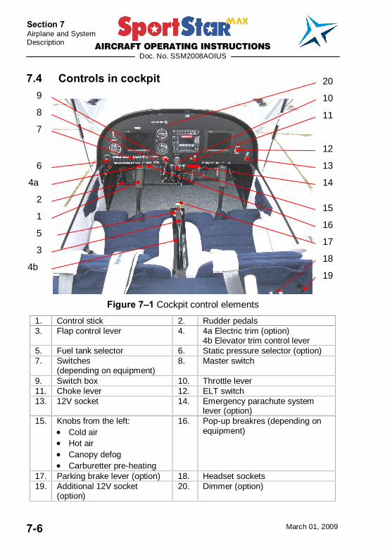
AIRCRAFT OPERATING INSTRUCTIONS
Doc. No. SSM2008AOIUS
March 01, 2009 7-6
Section 7 Airplane and System Description
7.4 Controls in cockpit
Figure 7�1 Cockpit control elements
1. Control stick 2. Rudder pedals 3. Flap control lever 4. 4a Electric trim (option)
4b Elevator trim control lever 5. Fuel tank selector 6. Static pressure selector (option) 7. Switches
(depending on equipment) 8. Master switch
9. Switch box 10. Throttle lever 11. Choke lever 12. ELT switch 13. 12V socket 14. Emergency parachute system
lever (option) 15. Knobs from the left:
Cold air Hot air Canopy defog Carburetter pre-heating
16. Pop-up breakres (depending on equipment)
17. Parking brake lever (option) 18. Headset sockets 19. Additional 12V socket
(option) 20. Dimmer (option)
1
8
18
5 17
4a
4b
13
7
9
12
10
19
11
2
3
6
14
15
16
20

AIRCRAFT OPERATING INSTRUCTIONS
Doc. No. SSM2008AOIUS
March 01, 2009 7-7
Section 7 Airplane and System
Description
7.5 Instrument panel See Section 9 � Supplements, Instrument panel is shown in Supplement No. 4 Aircraft Description.
7.6 Inside and outside marking and placards See Aircraft Maintenance and Inspection Procedures.
7.7 Landing gear and brakes
7.7.1 Landing gear The airplane is equipped with a sort of fixed nose landing gear. Main landing gear legs are produced from composite spring. Nose landing gear leg is welded from two pieces - the tube and the yoke- in which the nose wheel is mounted. The nose landing gear is spring-loaded by a rubber rope. The nose wheel is steerable, wheel control is coupled with rudder control by means of two pull rods. Wheels can be fitted with fiber-glass aerodynamic pants.
7.7.2 Brakes The SportStar MAX airplane is equipped with disk hydraulic brakes on main landing gear wheels. Brake system is composed of toe-brake pedals (these are a part of rudder control pedals), brake pumps, brake fluid reservoir, brake fluid central bottle on the firewall, hoses for leading brake liquid, brake yokes with wheel cylinders and brake pads. By depressing the brake pedals compression of brake pumps occurs, which generates pressure in brake circuit and hydraulic cylinders press the brake pads onto the brake disks. Braking pressure can be regulated only by force of brake pedals depressing.
The airplane can be equipped by mechanical manually controlled parking brake. PARKING BRAKE handle is located in front of the pilots, on the front wall of the fuel tank selector console.
7.8 Seat and safety harnesses SportStar MAX is a two-seat airplane with side-by-side seats. Seats are fixed, non-adjustable and fitted with light upholstery.
AIRCRAFT OPERATING INSTRUCTIONS
Doc. No. SSM2008AOIUS
March 01, 2009 7-8
Section 7 Airplane and System Description
Each of seats is fitted with four-point safety harness which is composed of safety belts, shoulder straps and lock. The safety harness is anchored in the fuselage sides behind the seats and on the seat sides.
7.9 Baggage compartment Baggage compartment is positioned behind seat rests. Maximum weight of baggage is 55 lbs (25 kg) and is stated on the placard in the baggage compartment. The baggage compartment is fitted with rubber net for baggage fixation.
WARNING It is prohibited to use a space behind baggage compartment for additional stowage. This is due to airplane aft C.G. limit.
7.10 Canopy The cocpit canopy is of a semidrop shape. The framework is composed of composite structure on which the organic glass canopy is stuck.
The canopy is attached to the fuselage in the front part by two swivel pins by means of which it can be folded up forwards. In order to make opening easier, the actual weight of canopy is balanced by two gas struts.
Lock The canopy is provided with an automotive lock in the rear upper part of the tip-up frame and key lock on the top of rear fixed frame.There is also a canopy open/close sensor installed in the lock, with indication of canopy open position by a red light on the instrument panel or red/green light on a display if a digital instruments like Dynon EFIS/EMS or TruTrak EFIS/EMS are installed.
Maintenance of automotive lock: Spray the lock with WD-40 spray annually from time to time
Check: Check the lock visually for deformations
Adjustment: Release the socket wrench screws on back of the lock, adjust lock position and tight the socket wrench screws
AIRCRAFT OPERATING INSTRUCTIONS
Doc. No. SSM2008AOIUS
March 01, 2009 7-9
Section 7 Airplane and System
Description
7.11 Power unit
7.11.1 General The engine ROTAX 912 ULS (100 hp) is standardly used to power SportStar MAX airplane. IFR version is fitted with certified ROTAX 912S. ROTAX 912 is a four-cylinder, four-stroke engine with opposite cylinders, central cam shaft and OHV valve mechanism.
The on-ground adjustable, composite, 3-blade propeller WOODCOMP KLASSIC 170/3/R is standardly mounted on the engine ROTAX 912 ULS.
IFR version is fitted with ground adjustable, 3-bladed, composite Warpdrive CF prop, with Nickel protection of blade leading edges.
Other propeller type can be installed on customer�s request - see Section 9 for detailed information .
7.11.2 Engine control Engine power is controlled by means of THROTTLE lever, which is located in the middle of the instrument panel and which controls engine power range from idle up to maximum take-off. Engine power controller is mechanically interconnected with the flap on carburetters.
If the lever is fully pushed in, then this position corresponds to maximum engine power. If the lever is fully pulled out, then this position corresponds to idle. Rapid changes in engine power setting can be made by pressing down the round button on the lever body and by its pulling out or pushing in. Small changes in power setting can be performed through lever turning (conterclockwise - power increase).
The lever is fitted with the locking ring, counterclockwise turning of which ensures locking of the lever in requested position.
7.11.3 Engine intruments The following analog instruments located on the instrument panel serve for engine performance monitoring. The digital engine monitoring system can be installed in the airplane instead of analog engine instruments.
AIRCRAFT OPERATING INSTRUCTIONS
Doc. No. SSM2008AOIUS
March 01, 2009 7-10
Section 7 Airplane and System Description
RPM indicator
The electrical RPM indicator is controlled by signal from the generator RPM transmitter. Working range of the RPM indicator is 0 - 7000 RPM. Color code is stated in 2.5.
Cylinder head thermometer
The cylinder head thermometer transmitter senses temperature of cylinder No. 3. Working range of the cylinder head thermometer is 120 300°F. Color code is stated in 2.5.
Oil thermometer
Oil temperature on engine input is measured by the sensor located behind the oil pump. Working range of oil thermometer is 120 300°F. Color code is stated in 2.5.
Oil pressure gauge
Oil pressure on the oil input into engine is measured by means of sensor which is located behing the oil filter. Working range is 0 150 PSI. Color code is stated in 2.5.
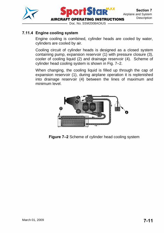
AIRCRAFT OPERATING INSTRUCTIONS
Doc. No. SSM2008AOIUS
March 01, 2009 7-11
Section 7 Airplane and System
Description
7.11.4 Engine cooling system Engine cooling is combined, cylinder heads are cooled by water, cylinders are cooled by air.
Cooling circuit of cylinder heads is designed as a closed system containing pump, expansion reservoir (1) with pressure closure (3), cooler of cooling liquid (2) and drainage reservoir (4). Scheme of cylinder head cooling system is shown in Fig. 7�2.
When changing, the cooling liquid is filled up through the cap of expansion reservoir (1), during airplane operation it is replenished into drainage reservoir (4) between the lines of maximum and minimum level.
Figure 7�2 Scheme of cylinder head cooling system
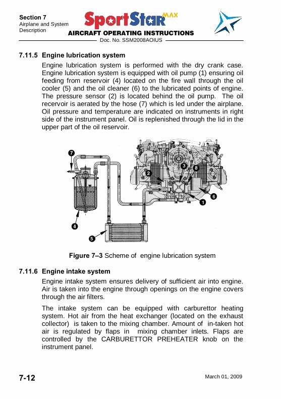
AIRCRAFT OPERATING INSTRUCTIONS
Doc. No. SSM2008AOIUS
March 01, 2009 7-12
Section 7 Airplane and System Description
7.11.5 Engine lubrication system Engine lubrication system is performed with the dry crank case. Engine lubrication system is equipped with oil pump (1) ensuring oil feeding from reservoir (4) located on the fire wall through the oil cooler (5) and the oil cleaner (6) to the lubricated points of engine. The pressure sensor (2) is located behind the oil pump. The oil recervoir is aerated by the hose (7) which is led under the airplane. Oil pressure and temperature are indicated on instruments in right side of the instrument panel. Oil is replenished through the lid in the upper part of the oil reservoir.
Figure 7�3 Scheme of engine lubrication system
7.11.6 Engine intake system Engine intake system ensures delivery of sufficient air into engine. Air is taken into the engine through openings on the engine covers through the air filters.
The intake system can be equipped with carburettor heating system. Hot air from the heat exchanger (located on the exhaust collector) is taken to the mixing chamber. Amount of in-taken hot air is regulated by flaps in mixing chamber inlets. Flaps are controlled by the CARBURETTOR PREHEATER knob on the instrument panel.
AIRCRAFT OPERATING INSTRUCTIONS
Doc. No. SSM2008AOIUS
March 01, 2009 7-13
Section 7 Airplane and System
Description
7.11.7 Ignition system The engine is equipped with the double contactless ignition system. Each ignition circuit has own source of energy, control unit, 2 ignition coils and 4 spark plugs. It is fully autonomous on the other circuit of accumulator. High voltage current is distributed to the spark plugs through high-voltage cables. Ignition sequence of individual engine cylinders:
Ignition circuits are controlled by the ignition switch on the instrument panel. Positions of ignition switch: OFF engine ignition is off R only ignition circuit B is on L only ignition circuit A is on BOTH both circuits are on START both circuits are on and starter is cranking the engine
7.12 Fuel system Fuel system serves for keeping fuel in the airplane and its feeding to the engine. Fuel system of SportStar MAX airplane is composed of integral fuel tanks, fuel line, fuel selector, fuel filter, mechanical fuel pump - located on the engine (auxiliary electrical fuel pump can be installed), distribution pipe of fuel with, return branch of fuel, fuel gauges and fuel tanks draining valves.
7.12.1 Fuel tanks Fuel is contained in the wing integral tanks. Each tank is fitted with air venting (output is under the wing tip) and draining valve on the bottom side of the wing. Fuel is led from the tanks through the hoses to the fuel selector located on a central console under the instrument panel and then through a fuel filter to the engine pump and carburetors. Fuel return hose goes from the fuel pump into the left tank, which is due to considered as a �primary� tank. See figure 7-4 for Scheme of fuel system.
7.12.2 Fuel selector The fuel selector serves for tank selection and fuel delivery interruption in case of engine fire or long parking of airplane. To move selector from OFF (closed) position it necessary pull the safety button on the fuel selector, turn the handle from the OFF position to the left and then release safety button. Now the handle
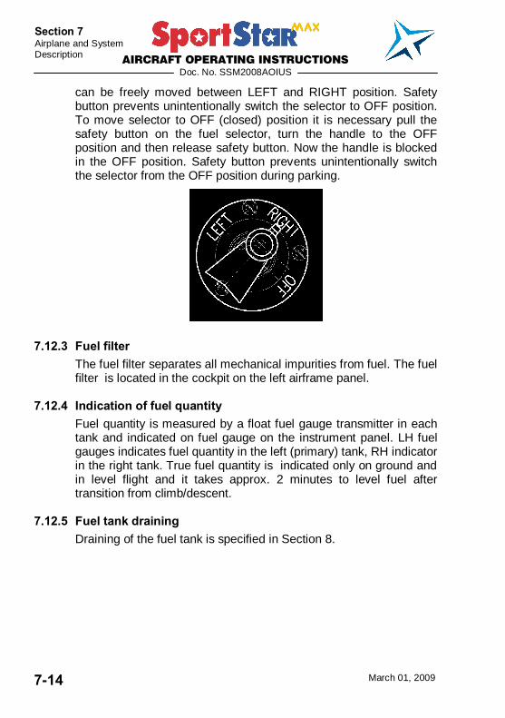
AIRCRAFT OPERATING INSTRUCTIONS
Doc. No. SSM2008AOIUS
March 01, 2009 7-14
Section 7 Airplane and System Description
can be freely moved between LEFT and RIGHT position. Safety button prevents unintentionally switch the selector to OFF position. To move selector to OFF (closed) position it is necessary pull the safety button on the fuel selector, turn the handle to the OFF position and then release safety button. Now the handle is blocked in the OFF position. Safety button prevents unintentionally switch the selector from the OFF position during parking.
7.12.3 Fuel filter The fuel filter separates all mechanical impurities from fuel. The fuel filter is located in the cockpit on the left airframe panel.
7.12.4 Indication of fuel quantity Fuel quantity is measured by a float fuel gauge transmitter in each tank and indicated on fuel gauge on the instrument panel. LH fuel gauges indicates fuel quantity in the left (primary) tank, RH indicator in the right tank. True fuel quantity is indicated only on ground and in level flight and it takes approx. 2 minutes to level fuel after transition from climb/descent.
7.12.5 Fuel tank draining Draining of the fuel tank is specified in Section 8.
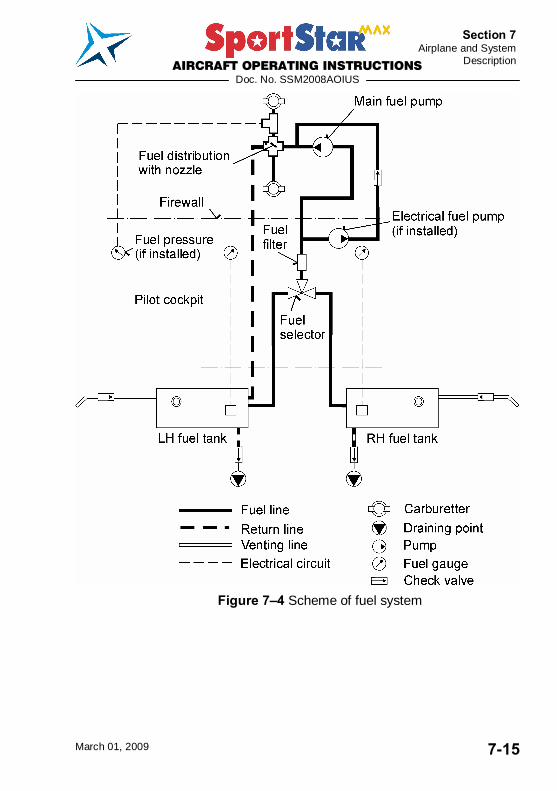
AIRCRAFT OPERATING INSTRUCTIONS
Doc. No. SSM2008AOIUS
March 01, 2009 7-15
Section 7 Airplane and System
Description
Figure 7�4 Scheme of fuel system
AIRCRAFT OPERATING INSTRUCTIONS
Doc. No. SSM2008AOIUS
March 01, 2009 7-16
Section 7 Airplane and System Description
7.13 Electrical system The airplane is equipped with 14 V DC electrical installation. A generator with power of 250 W is the primary source of electrical energy. The secondary source of energy is the accumulator 12V/16Ah that is located in the engine compartment on the firewall. It is used for engine starting and in case of generator failure as an emergency source of energy and also serves as the smoothing filter of power system.
Widely equipped airplanes (night VFR, IFR) are fitted with the auxiliary generator SD-20, mounted on the engine.
DC voltage is distributed to individual systems by main busbar. Each system is protected by circuit breaker. If overloading of any of the circuits occurs, then the circuit breaker is pulled out. Circuit beakers are listed in the Aircraft Maintenance and Inspection Procedures.
CAUTION DO NOT USE CIRCUIT BREAKERS FOR NORMAL SWITCHING OFF OF THE SYSTEMS
After switching MASTER SWITCH on and by turning the ignition key to START position the starter is activated. The starter is power supplied from the accumulator before engine start. After engine has been started and idle RPM reached, generator starts supplying current into electrical network.
Piper type external power socket can be installed optionally. The socket is located on the right side of the fuselage, behind the firewall.
Optionally 12V automotive socket located on the instrument panel can be installed, as well as an another 12V socket behind the co-pilot seat, next to the headphones sockets.
7.13.1 Lighting Airplane can be equipped with an external lighting.
External lighting can be composed of position lights and anticollision beacons which are located in wing tip and landing headlight which is located in left wing leading edge or in the lower engine cowling. Position lights are switched by POS. LIGHTS

AIRCRAFT OPERATING INSTRUCTIONS
Doc. No. SSM2008AOIUS
March 01, 2009 7-17
Section 7 Airplane and System
Description
switch and anticollision beacon by BEACON switch. Landing headlight is switched by LDG LIGHT switch.
Night VFR and IFR versions are equipped with the landing light, position lights & anticollision beacons. There is also a cockpit light installed for these versions.
7.13.2 Electrical system scheme See Aircraft Maintenance and Inspection Procedures - Supplements.

AIRCRAFT OPERATING INSTRUCTIONS
Doc. No. SSM2008AOIUS
March 01, 2009 7-18
Section 7 Airplane and System Description
7.14 Pitot-static system Pitot-static tube for sensing static and total pressure is located under the left half of the wing. Total pressure is sensed through the opening in the Pitot-static tube face. Static pressure is sensed through openings on the tube circumference. System of pressure distribution to individual instruments are made by means of flexible plastic hoses. Transparent draining reservoirs are located in the pressure branch of static and total pressure on the left fuselage side on the bottom next to wing leading edge.
Static pressure is led to altimeter, airspeed indicator, variometer and altitude encoder (if installed). Total pressure is led only to the airspeed indicator.
IFR version is equipped with an alternate pitot-static tube located under the right half of the wing. This pitot serves only as a source of alternate static pressure. Both Primary and Alternate pitots are heated. There is a static pressure select knob located on the instrument panel to switch from Primary to Alternate static pressure.
For scheme of IFR pitot-static system refer to IFR Supplement to this AOI.
Figure 7�5 Scheme of pitot-static system
AIRCRAFT OPERATING INSTRUCTIONS
Doc. No. SSM2008AOIUS
March 01, 2009 7-19
Section 7 Airplane and System
Description
7.15 Supplementary equipment
7.15.1 Ventilation and heating system Cockpit ventilation is ensured by 2 eye�ball vents located on the left and right of the tip-up canopy frame. Vents are connected to the NACA scoops through tip-up canopy frame front flaps.
Cockpit heating is provided by air conducted through a hose guided from a fiberglass collector behind the engine radiator into the heat exchanger and then into the mixture flap on the firewall and further through a directional flap to the cockpit floor or to the hot air outputs through the instrument panel cover as well as into the hollow spaces of the tip-up frame for defrosting. Hot air quantity is regulated by the HOT AIR knob, cold air quantity is regulated by the COLD AIR knob on the instrument panel. Proportion of the cold and hot air in the heating system can be set continuously. Other knob below the HOT AIR knob serves for air routing to the cockpit floor or on the canopy glass.
Defog / defrosting of windshield and sides is ensured by hot air conducted from a cold/hot air mixture flap on the firewall into the tip-up canopy frame and then through a row of holes onto the glass.
7.16 Navigation and communication equipment Description of operation of navigation and communication equipment see Section 9 - Supplements.


AIRCRAFT OPERATING INSTRUCTIONS
Doc. No. SSM2008AOIUS
March 01, 2009 8-1
Section 8 Airplane Handling,
Servicing and Maintenance
SECTION 8
8. AIRPLANE HANDLING SERVICING AND MAINTENACE
8.1 Introduction ....................................................................8-3
8.2 Airplane inspection period ............................................8-5
8.3 Modifications or airplane repairs ..................................8-5
8.4 Road transport ...............................................................8-6 8.4.1 Airplane towing ................................................................. 8-6 8.4.2 Airplane parking................................................................ 8-6 8.4.3 Airplane anchoring ............................................................ 8-7 8.4.4 Airplane jacking................................................................. 8-7 8.4.5 Levelling ........................................................................... 8-8 8.4.6 Road transport .................................................................. 8-8
8.5 Draining of fuel tank ......................................................8-8
8.6 Cleaning and care ..........................................................8-9

AIRCRAFT OPERATING INSTRUCTIONS
Doc. No. SSM2008AOIUS
March 01, 2009 8-2
Section 8 Airplane Handling, Servicing and Maintenance
Intentionally left blank
AIRCRAFT OPERATING INSTRUCTIONS
Doc. No. SSM2008AOIUS
March 01, 2009 8-3
Section 8 Airplane Handling,
Servicing and Maintenance
8.1 Introduction This section includes the procedures for airplaine handling, maintenance and operation recommended by the manufacturer.
It is necessary to follow the set-down lubrication plan, scope and periodocity of preventive maintenance depending on climatic and flight conditions according to the Aircraft Maintenance and Inspection Procedures of SportStar MAX Light Sport Aircraft
Airplane owner should be in a permanent touch with the manufacturer, either directly or through the network of business representatives, which enables him to get the newest information concerning airplane operation, handling and maintenance. The manufacturer distributes this information to users through Service bulletins (Mandatory bulletins), Information bulletins (letters) and further instructions.
Mandatory bulletins are especially important for keeping up airworthiness and the manufacturer considers them mandatory although they do not come into effect before Airworthiness Directive is issued by aviation authority of user�s country.
All correspondence with the airplane manufacturer, distributor or service center must contain the airplane serial number. The airplane serial number is shown on the title sheet of this Instructions and on the Manufacturer�s plate below stabilizer on the left side of the fuselage.
The manufacturer delivers along with aircraft SportStar MAX the �Aircraft Operating Instructions (AOI)� and the �Aircraft Maintenance and Inspection Procedures (AMIP)�.
Qualification requirements to perform maintenance and repairs are mentioned in the AMIP - item 4.1.1.
AIRCRAFT OPERATING INSTRUCTIONS
Doc. No. SSM2008AOIUS
March 01, 2009 8-4
Section 8 Airplane Handling, Servicing and Maintenance
Owner/Operator Responsibilities:
- Each owner/operator of an LSA airplane shall read and comply with the maintenance and continued airworthiness information and isntructions provided by the manufacturer.
- Each owner/operator of an LSA airplane shall be responsible for providing the manufacturer with current contact information where the manufacturer may send the owner/operator supplemental notification bulletins.
- The owner/operator of an LSA airplane shall be responsible for notifying the manufacturer of any safety of flight issue or significant service difficulty upon discovery.
- The owner/operator of an LSA airplane shall be responsible for complying with all manufacturer issued notices of corrective action and for complying with all applicable aviation authority regulations in regard to maintaining the airworthiness of the LSA airplane.
- An owner of an LSA airplane shall ensure that any needed corrective action must be completed as specified in a notice, or by the next scheduled annual inspection.
- Should an owner/operator not comply with any mandatory service requirement, the LSA airplane shall be considered not in compliance with applicable ASTM Standards and may be subject to regulatory action by the presiding aviation authority.

AIRCRAFT OPERATING INSTRUCTIONS
Doc. No. SSM2008AOIUS
March 01, 2009 8-5
Section 8 Airplane Handling,
Servicing and Maintenance
8.2 Airplane inspection period Periodical inspections and reviews of airplane must be carried out at the latest in the following intervals:
- after first 25 ± 2 hours of operation
- after every 50 ± 3 hours of operation - after every 100 ± 5 hours of operation - annual inspection Details on periodical inspections are provided in the Aircraft Maintenance and Inspection Procedures of SportStar MAX.
Refer to the Rotax 912 Operator�s Manual for engine maintenance. Refer to the Propeller Maintenance Manual for propeller maintenance.
8.3 Modifications or airplane repairs USA §91.327 requires: (5) Each alteration accomplished after the aircraft�s date of manufacture meets the applicable and current consensus standard and has been authorized by either the manufacturer or a person acceptable to the FAA; (6) Each major alteration to an aircraft product produced under a consensus standard is authorized, performed and inspected in accordance with maintenance and inspection procedures developed by the manufacturer or a person acceptable to the FAA; and (7) The owner or operator complies with the requirements for the recording of major repairs and major alterations performed on typecertificated products in accordance with §43.9 (d) of this chapter, and with the retention requirements in §91.417. Basic repairs of airplane are described in the Aircraft Maintenance and Inspection Procedures of SportStar MAX.

AIRCRAFT OPERATING INSTRUCTIONS
Doc. No. SSM2008AOIUS
March 01, 2009 8-6
Section 8 Airplane Handling, Servicing and Maintenance
8.4 Road transport
8.4.1 Airplane towing It is possible to move the airplane on a short distance by holding the fuselage end in the position before the fin, enventually by holding the root part of wings.
The hand towing bar can be used for airplane relocation which will be fastened to the nose wheel axis.
To turn the airplane on the spot, push on the fuselage end part in the area before the fin, lift the nose wheel and turn the airplane in required direction.
WARNING SWITCH OFF IGNITION BEFORE GROUND HANDLING WITH THE AIRPLANE!
CAUTION AVOID EXCESSIVE PRESSURES ON THE AIRFRAME STRUCTURE, ESPECIALLY ON THE WING TIPS, HTU, VTU ETC.
WHEN HANDLING THE AIRPLANE BY MEANS OF THE TOWING BAR, PROPELLER BLADES MUST BE SET ONE BLADE UP (THREE BLADE PPROPELLER). MAXIMUM DEFLECTION OF THE NOSE WHEEL IS ± 10°.
AT MANUAL ENGINE STARTING GRASP THE PROPELLER BLADE AREA, I.E. NOT ONLY PROPELLER EDGE.
8.4.2 Airplane parking It is the most suitable solution to place the airplane into a hangar possibly into another covered room with stable temperature, good venting, low humidity and dust-free environment. In case of parking out of the hangar it is necessary to anchor the airplane and at long-term parking to cover the canopy, possibly the whole airplane with suitable tarpaulins.
AIRCRAFT OPERATING INSTRUCTIONS
Doc. No. SSM2008AOIUS
March 01, 2009 8-7
Section 8 Airplane Handling,
Servicing and Maintenance
8.4.3 Airplane anchoring The airplane is anchored at parking out of hangar after termination of flight day or according to need. Anchoring of the airplane is necessary for its protection against possible damage, caused by wings and gusts. For this purpose the airplane is equipped with fixing eyes on the lower side of wings and under the tail skid.
Procedure:
1. Check of fuel selector, off-position of all switches, ignition and master switch.
2. Lock manual control, e.g. by using safety belts
3. Close and lock the cockpit canopy
4. Anchor the airplane to the ground by means of cables pulled through fixing eyes which are located on the lower side of wings. Further it is necessary to anchor the nose landing gear.
NOTE In case that long-term airpplane anchoring is supposed, namely in winter period, it is suitable to cover the canopy, eventually the whole airplane by appropriate tarpaulins which must be properly secured to the airplane structure.
8.4.4 Airplane jacking Airplane jacking presents no big difficulties due to relatively low airplane empty weight and can be performed by two persons.
First, it is necessary to prepare two suitable rests which will support the airplane.
The airplane can be jacked in the following way: - by pushing from the above to the fuselage rear part in the
position before the fin the front part of fuselage can be jacked and subsequently supported under the fire wall.
- Rear part of fuselage can be slightly jacked only by grasping in the position near the auxiliary skid and by pushing from below and then the lower part of fuselage can be supported by the rest located in the area of the skid.

AIRCRAFT OPERATING INSTRUCTIONS
Doc. No. SSM2008AOIUS
March 01, 2009 8-8
Section 8 Airplane Handling, Servicing and Maintenance
- Wings can be jacked by pushing on the wing from below in the area of the main spar. It is necessary to avoid jacking by grasping the wing tip.
8.4.5 Levelling Levelling procedure is described in the Aircraft Maintenance and Inspection Procedures for SportStar MAX airplane.
8.4.6 Road transport The airplane can be transported on communication after its loading on an appropriate trail. It is necessary to dismount wings. The airplane must be secured against possible movement. This way you will preclude possible damage to the airplane.
8.5 Draining of fuel tank Draining should be done prior to first flight each day. There is a drain valve of each wing tank located on its bottom.
Procedure:
1. Put a transparent cup under the drain valve.
2. Using screwdriver (or appropriate jig) press and turn drain valve counterclockwise to open it.
3. Drain required quantity of fuel.
NOTE Draining serves to elimination of impurities and deposits from the fuel. Drain until clean fuel flows from the drain valve.
4. Using screwdriver (or appropriate jig) turn drain valve clockwise to close it.
5. Repeat procedure for the opposite tank.
AIRCRAFT OPERATING INSTRUCTIONS
Doc. No. SSM2008AOIUS
March 01, 2009 8-9
Section 8 Airplane Handling,
Servicing and Maintenance
8.6 Cleaning and care Always use appropriate cleaning agents when cleaning airplane surface. Residuum of oil and fat can be removed form the airplane surface (excluding the canopy) by suitable detergents, posibbly by petrol.
The canopy only to be cleaned by washing with ample stream of tepid water with addition of appropriate detergents. Use soft rag, sponge or wash leather. Use suitable polishing agent after wiping rests of water.
CAUTION NEVER DRY-CLEAN THE CANOPY AND NEVER USE PETROL NOR CHEMICAL SOLVENTS!
Coating, upholstery and carpets in the cocpit can be removed from the cocpit, brushed and, if need be, cleaned with warm water with addition of appropriate detergent. Dry up upholstery after doing this.

AIRCRAFT OPERATING INSTRUCTIONS
Doc. No. SSM2008AOIUS
March 01, 2009 8-10
Section 8 Airplane Handling, Servicing and Maintenance
Intentionally left blank
AIRCRAFT OPERATING INSTRUCTIONS
Doc. No. SSM2008AOIUS
March 01, 2009 9-1
Section 9 Supplements
SECTION 9
9. SUPPLEMENTS 9.1 Introduction ....................................................................9-2
9.2 List of inserted supplements.........................................9-2
9.3 Supplements inserted....................................................9-4

AIRCRAFT OPERATING INSTRUCTIONS
Doc. No. SSM2008AOIUS
March 01, 2009 9-2
Section 9 Supplements
9.1 Introduction This section contains the appropriate supplements necessary to safely and efficiently operate the airplane when equipped with various optional systems and equipment not provided with the standard airplane.
9.2 List of inserted supplements Inst. Date Doc. No. Title of inserted supplement
March 01/09 SSM2008AOIUSS01 Transceiver KY97A
March 01/09 SSM2008AOIUSS02 Intercom PM 1000
March 01/09 SSM2008AOIUSS03 Transponder KT76A
March 01/09 SSM2008AOIUSS04 Airplane description of S/N
March 01/09 SSM2008AOIUSS05 GPS/COMM receiver KLX 135
March 01/09 SSM2008AOIUSS06 Flight clock LC-2
March 01/09 SSM2008AOIUSS07 Transceiver FILSER ATR 600
March 01/09 SSM2008AOIUSS08 GPS/NAV/COMM receiver GARMIN GNS 430/430A
March 01/09 SSM2008AOIUSS09 Transponder ATC GARMIN GTX 327
March 01/09 SSM2008AOIUSS10 Intercom PCD7100-I (PS ENGINEERING INCORPORATED)
March 01/09 SSM2008AOIUSS11 Rocket activated parachute rescue system Magnum Speed Soft 650
March 01/09 SSM2008AOIUSS12 Horizon RCA 26
March 01/09 SSM2008AOIUSS13 Float operation CZAW 1150
March 01/09 SSM2008AOIUSS14 Horizon LUN 1202
March 01/09 SSM2008AOIUSS15 Towing gear
March 01/09 SSM2008AOIUSS16 Pitot tube heating
March 01/09 SSM2008AOIUSS17 Emergency Locator Transmitter AK-450
- - SSM2008AOIUSS18 Not used
March 01/09 SSM2008AOIUSS19 Stall warning system ACI type T1b
March 01/09 SSM2008AOIUSS20 Night VFR operation
March 01/09 SSM2008AOIUSS21 IFR operation
AIRCRAFT OPERATING INSTRUCTIONS
Doc. No. SSM2008AOIUS
March 01, 2009 9-3
Section 9 Supplements
Inst. Date Doc. No. Title of inserted supplement

AIRCRAFT OPERATING INSTRUCTIONS
Doc. No. SSM2008AOIUS
March 01, 2009 9-4
Section 9 Supplements
9.3 Supplements inserted

AIRCRAFT OPERATING INSTRUCTIONS
Doc. No. SSM2008AOIUS
March 01, 2009 9-5
Section 9 Supplements
Intentionally left blank