aircraft powerplant 1 classification and progress chapter 1 aircraft powerplant classification and...
TRANSCRIPT

1The first practical gas engine was built in 1860 by a
French inventor named Jean Joseph Étienne Lenoir. This engine utilized illuminating gas as a fuel, and ignition of the fuel was provided by a battery system. Within a few years, approximately 400 of these engines had been built to operate a variety of machinery, such as lathes and printing presses.
The first four-stroke-cycle engine was built by August Otto and Eugen Langen of Germany in 1876. As a result, four-stroke-cycle engines are often called Otto-cycle engines. Otto and Langen also built a two-stroke-cycle engine.
In the United States, George B. Brayton, an engineer, built an engine using gasoline as fuel and exhibited it at the 1876 Centennial Exposition in Philadelphia. The first truly success-ful gasoline engine operating according to the four-stroke-cycle principle was built in Germany in 1885 by Gottlieb Daimler, who had previously been associated with Otto and Langen. A similar gasoline engine was built by Karl Benz of Germany in the same year. The Daimler and Benz engines were used in early automobiles, and the engines used today are similar in many respects to the Daimler and Benz engines.
The First Successful Airplane Engine
Inasmuch as the first powered flight in an airplane was made by the Wright brothers on December 17, 1903, it is safe to say that the first successful gasoline engine for an airplane was the engine used in the Wright airplane. This engine was designed and built by the Wright brothers and their mechanic, Charles Taylor. The engine had the following characteristics: (1) water cooling; (2) four cylinders; (3) bore, 4 3
8 inches (in) [11.11 centimeters (cm)], and stroke, 4 in [10.16 cm]; dis-placement, 240 cubic inches (in3) [3 932.9 cm3]; (4) 12 horse-power (hp) [8.94 kilowatts (kW)]; (5) weight, 180 pounds (lb) [82 kilograms (kg)]; (6) cast-iron cylinders with sheet-aluminum water jackets; (7) valve-in-head with the exhaust valve mechanically operated and the intake valve automati-cally operated; (8) aluminum-alloy crankcase; (9) carbure-tion by means of fuel flow into a heated manifold; and (10) ignition by means of a high-tension magneto. A picture of an early Wright engine is shown in Fig. 1-1.
World War I Aircraft Engines
The extensive development and use of airplanes during World War I contributed greatly to the improvement of engines.
1
Aircraft Powerplant Classification and Progress1
IntroductIon
People have dreamed of flying ever since they first gazed into the sky and saw birds soaring overhead. Early attempts at flight often resulted in failure. This fail-ure was not primarily due to airfoil design but instead was attributable to the lack of technology needed to produce a source of power sufficient to sustain flight.
The development of aviation powerplants has resulted from utilization of principles that were employed in the design of earlier internal-combustion engines. During the latter part of the nineteenth cen-tury, a number of successful engines were designed and built and used to operate machinery and to supply power for “horseless carriages.”
Since the first internal-combustion engine was suc-cessfully operated, many different types of engines have been designed. Many have been suitable for the opera-tion of automobiles and/or aircraft, and others have been failures. The failures have been the result of poor efficiency, lack of dependability (owing to poor design and to materials which could not withstand the operat-ing conditions), high cost of operation, excessive weight for the power produced, and other deficiencies.
The challenge to aviation has been to design engines that have high power-to-weight ratios. This was accom-plished first with lightweight piston engines and then, more effectively, with gas-turbine engines.
In this chapter we examine the evolution, design, and classification of various types of engines.
Early Engines
Development of the internal-combustion engine took place largely during the nineteenth century. One of the first such engines was described in 1820 by the Reverend W. Cecil in a discourse before the Cambridge Philosophical Society in England. This engine operated on a mixture of hydrogen and air. In 1838 the English inventor William Barnett built a single-cylinder gas engine which had combustion chambers at both the top and the bottom of the piston. This engine burned gaseous fuel rather than the liquid fuel used in the modern gasoline engine.
01_Kroes_Wild_Ch01_p001-028.indd 1 11/05/13 12:06 PM

2 Chapter 1 Aircraft Powerplant Classification and Progress
Rotary-Type Radial Engines
One type of engine that found very extensive use was the air-cooled rotary-type radial engine. In this engine the crankshaft is held stationary, and the cylinders rotate about the crankshaft. Among the best-known rotary engines were the LeRhone, shown in Fig. 1-2, the Gnome-Monosoupape, shown in Fig. 1-3, and the Bentley, which has a similar appearance. In these engines, the crankshaft is secured to the aircraft engine mount, and the propeller is attached to the engine case.
Even though the rotary engines powered many World War I airplanes, they had two serious disadvantages: (1) the torque and gyro effects of the large rotating mass of the engines made the airplanes difficult to control; and (2) the engines used cas-tor oil as a lubricant, and since the castor oil was mixed with the fuel of the engine in the crankcase, the exhaust of the engines contained castor-oil fumes which were often nauseat-ing to the pilots.
In-Line Engines
A number of in-line engines were also developed during World War I. Among these was the Hispano-Suiza engine, shown in Fig. 1-4.
The cylinders of an in-line engine are arranged in a single row parallel to the crankshaft. The cylinders are either upright above the crankshaft or inverted, that is, below the crank-shaft. The inverted configuration is generally employed. A typical inverted in-line engine is shown in Fig. 1-5. The engine shown is a Menasco Pirate, model C-4. The number of cylinders in an in-line engine is usually limited to six, to facilitate cooling and to avoid excessive weight per horse-power. There are generally an even number of cylinders in order to provide a proper balance of firing impulses. The in-line engine utilizes one crankshaft. The crankshaft is located above the cylinders in an inverted engine. The engine may be either air-cooled or liquid-cooled; however, liquid-cooled types are seldom utilized at present.
Figure 1-1 Early Wright engine.
Figure 1-2 LeRhone rotary engine.
Figure 1-3 Gnome-Monosoupape rotary engine.
Figure 1-4 Early Hispano-Suiza engine.
01_Kroes_Wild_Ch01_p001-028.indd 2 11/05/13 12:06 PM

Introduction 3
Use of the in-line-type engine is largely confined to low-and medium-horsepower applications for small aircraft. The engine presents a small frontal area and is therefore adapted to streamlining and a resultant low-drag nacelle configuration. When the cylinders are mounted in the inverted position, greater pilot visibility and a shorter land-ing gear are possible. However, the in-line engine has a greater weight-to-horsepower ratio than those of most other types. When the size of an aircraft engine is increased, it becomes increasingly difficult to cool it if it is the air cooled in-line type; therefore, this engine is not suitable for a high-horsepower output.
V-Type Engines
World War I saw the development of several V-type engines, including the Rolls-Royce V-12 engine, the U.S.-made Lib-erty V-12 engine, shown in Fig. 1-6, and several German engines. The V-type engine has the cylinders arranged on the crankcase in two rows (or banks), forming the letter V, with an angle between the banks of 90, 60, or 45°. There are always an even number of cylinders in each row.
Since the two banks of cylinders are opposite each other, two sets of connecting rods can operate on the same crank-pin, thus reducing the weight per horsepower as compared with the in-line engine. The frontal area is only slightly greater than that of the in-line type; therefore, the engine cowling can be streamlined to reduce drag. If the cylin-ders are above the crankshaft, the engine is known as the upright-V-type engine, but if the cylinders are below the crankshaft, it is known as an inverted-V-type engine. Bet-ter pilot visibility and a short landing gear are possible if the engine is inverted.
Post-World War I Engines
After World War I, many different engine designs were developed. Some of those with rather unusual configurations are shown in Fig. 1-7.
A popular U.S. engine was the Curtiss OX-5 engine man-ufactured during and after World War I. This engine powered the Curtiss Jennie (JN- 4) trainer plane used for training U.S. military aviators. After the war, many were sold to the pub-lic, and the majority were used in the early barnstorming days for air shows and passenger flights. An OX-5 engine is shown in Fig. 1-8.
Other engines developed in the United States between World War I and World War II were the Wright Hisso (a U.S.-built Hispano-Suiza), the Packard V-12, the Curtiss D -12 (a V-12 engine), the Wright Whirlwind and radial engines, and the Pratt & Whitney Wasp and Hornet engines, which are air-cooled radial types. Numerous smaller engines were also designed and built, including radial, opposed-cylinder, and in-line types.
Radial Engines
The radial engine has been the workhorse of military and commercial aircraft ever since the 1920s, and during World War I radial engines were used in all U.S. bombers and transport aircraft and in most of the other categories of aircraft. They were developed to a peak of efficiency and dependability; and even today, in the jet age, many are still in operation throughout the world in all types of duty.
A single-row radial engine has an odd number of cylin-ders extending radially from the centerline of the crankshaft. The number of cylinders usually ranges from five to nine. The cylinders are arranged evenly in the same circular plane, and all the pistons are connected to a single-throw 360° crank-shaft, thus reducing both the number of working parts and the weight.
A double-row radial engine resembles two single-row radial engines combined on a single crankshaft, as shown in Fig. 1-9. The cylinders are arranged radially in two rows, and each row has an odd number of cylinders. The usual number of cylinders used is either 14 or 18, which means that the same effect is produced as having either two seven-cylinder engines or two nine-cylinder engines joined on one crankshaft. A two-throw 180° crankshaft is used to permit the cylinders in each row to be alternately staggered on the common crankcase. That is, the cylinders of the rear
Figure 1-5 Inverted in-line engine.
Figure 1-6 Liberty engine.
01_Kroes_Wild_Ch01_p001-028.indd 3 11/05/13 12:06 PM

4 Chapter 1 Aircraft Powerplant Classification and Progress
row are located directly behind the spaces between the cyl-inders in the front row. This allows the cylinders in both rows to receive ram air for the necessary cooling.
The radial engine has the lowest weight-to-horsepower ratio of all the different types of piston engines. It has the disadvantage of greater drag because of the area presented to the air, and it also has some problems in cooling. Never-theless, the dependability and efficiency of the engine have made it the most widely used type for large aircraft equipped with reciprocating engines.
Multiple-Row Radial Engine
The 28-cylinder Pratt & Whitney R-4360 engine was used extensively at the end of World War II and afterward for both bombers and transport aircraft. This was the largest and most powerful piston-type engine built and used successfully in the United States. A photograph of this engine is shown in
(A)
(B)
(C)
(D) (E)
Figure 1-7 Different engine configurations developed after World War I. (A) Szekeley, 3-cylinder radial; (B) Italian MAB, 4-cylin-der fan-type engine; (C) British Napier “Rapier,” 16-cylinder H-type engine; (D) British Napier “Lion,” 12-cylinder W-type engine; (E) U.S. Viking, 16-cylinder X-type engine.
Figure 1-8 Curtiss OX-5 engine.
01_Kroes_Wild_Ch01_p001-028.indd 4 11/05/13 12:06 PM

Engine Design and Classification 5
Fig. 1-10. Because of the development of the gas-turbine engine, the very large piston engine has been replaced by the more powerful and lightweight turboprop and turbojet engines. Since it has few moving parts compared with the piston engine, the gas-turbine engine is more trouble-free and its maintenance cost is reduced. Furthermore, the time between overhauls (TBO) is greatly increased.
Opposed, Flat, or O-Type Engine
The opposed-type engine is most popular for light conven-tional aircraft and helicopters and is manufactured in sizes delivering from less than 100 hp [74.57 kW] to more than 400 hp [298.28 kW]. These engines are the most efficient, dependable, and economical types available for light air-craft. Gas-turbine engines are being installed in some light aircraft, but their cost is still prohibitive for the average, pri-vate airplane owner.
The opposed-type engine is usually mounted with the cylinders horizontal and the crankshaft horizontal; however, in some helicopter installations the crankshaft is vertical. The engine has a low weight-to-horsepower ratio, and because of its flat shape it is very well adapted to streamlining and to horizontal installation in the nacelle. Another advantage is that it is reasonably free from vibration. Figure 1-11 illus-trates a modern opposed engine for general aircraft use.
EngInE DESIgn AnD CLASSIFICATIOn
Conventional piston engines are classified according to a variety of characteristics, including cylinder arrange-ment, cooling method, and number of strokes per cycle. The most satisfactory classification, however, is by cyl-inder arrangement. This is the method usually employed because it is more completely descriptive than the other classifications. Gas-turbine engines are classified accord-ing to construction and function; these classifications are discussed in Chap. 11.
Cylinder Arrangement
Although some engine designs have become obsolete, we mention the types most commonly constructed throughout the history of powerplants. Aircraft engines may be classified according to cylinder arrangement with respect to the crank-shaft as follows: (1) in-line, upright; (2) in-line, inverted; (3) V type, upright; (4) V type, inverted; (5) double-V or fan type; (6) X type; (7) opposed or flat type; (8) radial type, single-row; (9) radial type, double-row; (10) radial type, multiple-row or “corncob.” The simple drawings in Fig. 1-12 illustrate some of these arrangements.
Figure 1-9 Double-row radial engine.
01_Kroes_Wild_Ch01_p001-028.indd 5 11/05/13 12:06 PM

6 Chapter 1 Aircraft Powerplant Classification and Progress
Figure 1-10 Pratt & Whitney R-4360 engine. (Pratt & Whitney.)
Figure 1-11 Teledyne Continental six-cylinder opposed engine. (Teledyne Continental.)
01_Kroes_Wild_Ch01_p001-028.indd 6 11/05/13 12:06 PM

Engine Design and Classification 7
The double-V- or fan-type engine has not been in use for many years, and the only piston engines in extensive use for aircraft in the United States at present are the opposed and radial types. A few V-type and in-line engines may still be in operation, but these engines are no longer manufactured in the United States for general aircraft use.
Early Designations
Most of the early aircraft engines, with the exception of the rotary types, were water-cooled and were of either in-line or V-type design. These engines were often classified as liquid-cooled in-line engines, water-cooled in-line engines, liquid-cooled V-type engines, or water-cooled V-type engines. As air-cooled engines were developed, they were classified in a similar manner (air-cooled in-line, air-cooled V-type, etc.).
Classification or Designation by Cylinder Arrangement and Displacement
Current designations for reciprocating engines generally employ letters to indicate the type and characteristics of the engine, followed by a numerical indication of displacement. The following letters usually indicate the type or character-istic shown:
L Left-hand rotation for counterrotating propeller
T Turbocharged with turbine-operated device
V Vertical, for helicopter installation with the crank-shaft in a vertical position
H Horizontal, for helicopter installation with the crankshaft horizontal
A Aerobatic; fuel and oil systems designed for sus-tained inverted flight
I Fuel injected; continuous fuel injection system installed
G Geared nose section for reduction of propeller rev-olutions per minute (rpm)
S Supercharged; engine structurally capable of oper-ating with high manifold pressure and equipped with either a turbine-driven supercharger or an engine-driven supercharger
O Opposed cylindersR Radial engine; cylinders arranged radially around
the crankshaft
However, note that many engines are not designated by the foregoing standardized system. For example, the Continental W-670 engine is a radial type, whereas the A-65, C-90, and E-225 are all opposed-type engines. V-type engines and inverted in-line engines have such designations as V and I. In every case, the technician working on an engine must interpret the designation cor-rectly and utilize the proper information for service and maintenance.
The two- or three-digit numbers in the second part of the engine designation indicate displacement to the nearest 5 in3. An engine with a displacement of 471 in3 [7.72 liters (L)] is shown as 470, as is the case with the Teledyne Conti-nental O-470 opposed engine.
In some cases, the displacement number will end with a figure other than zero. In such a case, this is a special indica-tion to reveal a characteristic such as an integral accessory drive.
Radial engines generally employ only the letter R fol-lowed by the displacement. For example, the R-985 is a single-row radial engine having a displacement of approxi-mately 985 in3 [16.14 L].
An example of the standard designation for an engine is as follows.
G TS I O -520 -E 1 B 4 D
DUALMAGENETO MODE4COUNTERWEIGHTS B–TYPEACCESSORYSECTION NO.1NOSESECTION E–TYPECRANKCASE 520–IN3DISPLACEMENT[85.21L] OPPOSED–TYPEENGINE EQUIPPEDWITHCONTINUOUSFUELINJECTION TURBOSUPERCHARGEDENGINE EQUIPPEDWITHPROPELLERGEARREDUCTION
A system of suffix designations has also been estab-lished to provide additional information about engines. The first suffix letter indicates the type of power section and the rating of the engine. This letter is followed by a number from 1 to 9, which gives the design type of the nose section. Following the nose-section number is a letter indicating the type of accessory section, and after this let-ter is a number which tells what type of counterweight application is used with the crankshaft. This number indi-cates the mode of vibration, such as 4, 5, or 6. The mode number is found on the counterweights or dynamic bal-ances on the crankshaft.
Figure 1-12 Engines classified according to cylinder arrangement.
01_Kroes_Wild_Ch01_p001-028.indd 7 11/05/13 12:06 PM
8 Chapter 1 Aircraft Powerplant Classification and Progress
The final character in the designation suffix may be a let-ter indicating the type of magneto utilized with the engine. The letter D indicates a dual magneto.
Engine Classification by Cooling Method
Aircraft engines may be classified as being cooled either by air or by liquid; however, few liquid-cooled engines are in operation. Most aircraft engines are cooled by passing air over the engine’s cylinders; through the con-vection process, excessive heat generated by the engine’s combustion process is removed from the engine. In a liquid-cooled engine, the liquid is circulated through the engine areas that require heat removal. After the heat has been transferred to the liquid, the liquid passes through a heat exchanger which cools the liquid, and the cycle repeats. A complete discussion of engine cooling systems is presented in Chapter 5.
Progress in Design and Types of Current Reciprocating Engines
Engineers who specialize in the design of aircraft power-plants have used light alloy metals for construction of the engines and have adopted weight-saving cylinder arrange-ments, with the result that today the weight per horsepower on several engines is below 1.2 lb [0.54 kg] and on some less than 1 lb [0.45 kg].
Airplanes have increased in size, carrying capacity, and speed. With each increase has come a demand for more power, and this has been met by improvements in engine and propeller design and by the use of gas turbine and turbo-prop engines. As piston engines increased in power, they became more complicated. The early powerplant engineers and mechanics had only a few comparatively simple prob-lems to solve, but the modern powerplant specialist must be familiar with the principles of the internal-combustion engine; the classification, construction, and nomenclature of engines; their fuel and carburetion systems; supercharging and induction systems; lubrication of powerplants; engine starting systems; ignition systems; valve and ignition timing; engine control systems; and propellers.
Fundamentally, the reciprocating internal-combustion engine that we know today is a direct descendant of the first Wright engine. It has become larger, heavier, and much more powerful, but the basic principles are essentially the same. However, the modern reciprocating aircraft engine has reached a stage in its development where it is faced with what is commonly called the theory of diminishing returns. More cylinders are added to obtain more power, but the resulting increases in size and weight complicate matters in many directions. For example, the modern reciprocating engine may lose more than 30 percent of its power in drag-ging itself and its nacelle through the air and in providing necessary cooling.
The improvement in reciprocating engines has become quite noticeable in the smaller engines used for light aircraft. This has been accomplished chiefly with the opposed-type four- and six-cylinder engines. Among the improvements
developed for light engines are geared propellers, super-chargers, and fuel injection systems. Whereas light airplanes were once limited to flight at comparatively low altitudes, today many are capable of cruising at altitudes of well over 20,000 feet (ft) [6 096 meters (m)].
Examples of Certified Reciprocating Engines
Many modern reciprocating engines for light certified air-craft (certificated under FAR part 33) are manufactured by Continental Motors, Inc. and Lycoming, a division of AVCO Corp. Although over time engine types can vary somewhat, some basic engine series will be presented.
Continental Motors Series Engines
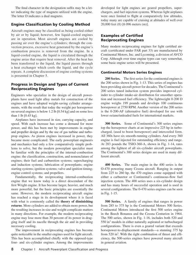
200 Series. The first series for the continental engines is the 200 series shown in Fig. 1-13. This series of engines has been providing aircraft power for decades. The Continental’s 200 series tuned induction system provides improved cyl-inder to cylinder intake-air distribution for smoother opera-tion and increased fuel efficiency. The lightweight 0-200 D engine weighs 199 pounds and develops 100 continuous horsepower at 2750 RPM. Another version of the 200 series is the 0-200-AF (alternative fuel) developed for use with lower octane/unleaded fuels for international markets.
300 Series. Some of Continental’s 300 series engines top the horsepower charts at an impressive 225 hp in turbo-charged, (used to boost horsepower) and intercooled form. All 360s have six smooth-running cylinders. And every 360 engine is fuel injected for outstanding efficiency and range. At 283 pounds the TSIO-360-A, shown in Fig. 1-14, rates among the lightest of all six-cylinder aircraft powerplants. The Continental’s 300 series designs are used in many dif-ferent aircraft.
400 Series. The main engine in the 400 series is the O-470 powering many Cessna aircraft. Ranging in output from 225 to 260 hp, the 470 engines come equipped with either a carburetor or Continental’s continuous-flow fuel injection system. The 400 series uses a six-cylinder design and has many hours of successful operation and is used in several configurations. The 0-470 series engines can be seen in Fig. 1-15.
500 Series. A family of engines that ranges in power from 285 to 375 hp is the Continental Motors 500 Series. Continental Motors introduced the first 500 series engine in the Beech Bonanza and the Cessna Centurion in 1964. The 500 series, shown in Fig. 1-16, includes both 520 and 550 in3 models in either naturally aspirated or turbocharged configurations. There is even a geared variant that exceeds horsepower-to-displacement standards—a stunning 375 hp from 520 in3. With the right combination of thrust and effi-ciency, the 500-series engines have powered many aircraft in general aviation.
01_Kroes_Wild_Ch01_p001-028.indd 8 11/05/13 12:06 PM
Engine Design and Classification 9
Lycoming Series Engines
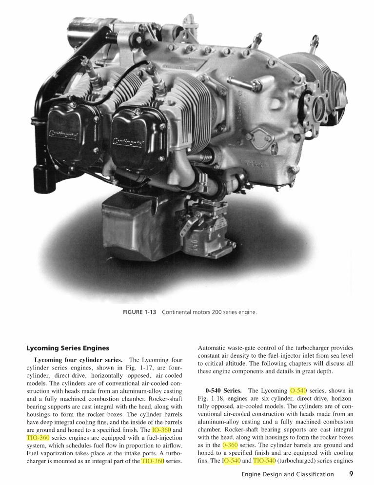
Lycoming four cylinder series. The Lycoming four cylinder series engines, shown in Fig. 1-17, are four-cylinder, direct-drive, horizontally opposed, air-cooled models. The cylinders are of conventional air-cooled con-struction with heads made from an aluminum-alloy casting and a fully machined combustion chamber. Rocker-shaft bearing supports are cast integral with the head, along with housings to form the rocker boxes. The cylinder barrels have deep integral cooling fins, and the inside of the barrels are ground and honed to a specified finish. The IO-360 and TIO-360 series engines are equipped with a fuel-injection system, which schedules fuel flow in proportion to airflow. Fuel vaporization takes place at the intake ports. A turbo-charger is mounted as an integral part of the TIO-360 series.
Automatic waste-gate control of the turbocharger provides constant air density to the fuel-injector inlet from sea level to critical altitude. The following chapters will discuss all these engine components and details in great depth.
0-540 Series. The Lycoming O-540 series, shown in Fig. 1-18, engines are six-cylinder, direct-drive, horizon-tally opposed, air-cooled models. The cylinders are of con-ventional air-cooled construction with heads made from an aluminum-alloy casting and a fully machined combustion chamber. Rocker-shaft bearing supports are cast integral with the head, along with housings to form the rocker boxes as in the 0-360 series. The cylinder barrels are ground and honed to a specified finish and are equipped with cooling fins. The IO-540 and TIO-540 (turbocharged) series engines
Figure 1-13 Continental motors 200 series engine.
01_Kroes_Wild_Ch01_p001-028.indd 9 11/05/13 12:06 PM

10 Chapter 1 Aircraft Powerplant Classification and Progress
are equipped with a fuel-injection system, which schedules fuel flow and delivers vaporized fuel at the intake ports in proportion to airflow. A turbocharger(s) is mounted as an integral part of the TIO-540 series. The turbocharger pro-vides constant air density to the fuel-injector inlet. Some of the Lycoming series engines can be equipped with high compression heads, which increases the horsepower output.
IO-390 Series. The Lycoming IO-390 series engines are four-cylinder, direct-drive, horizontally opposed, air-cooled models. The engines are equipped with a fuel-injection sys-tem that schedules fuel flow in proportion to airflow. Fuel vaporization takes place at the intake ports. Implementing new technology in cylinder design proven by the perfor-mance of the 580 engine series to increase the displacement to 390 in3, this model produces 210 hp at 2700 RPM and consumes 11.1 gallons per hour at 65% power. Designed to meet the growing demand for kit aircraft, the engine provides the required speed, payload, and low fuel consumption.
IO-580 Series. The Lycoming IO-580 series engines are six-cylinder, direct-drive horizontally opposed, air-cooled models, see Fig. 1-19. The cylinders are of conventional
air-cooled construction with heads made from an aluminum- alloy casting and a fully machined combustion chamber. The engines are equipped with a fuel-injection system. The fuel injector meters fuel in proportion to induction air-flow to air-bled nozzles at individual cylinder intake ports. Manual mixture control and idle cutoff are provided. This engine has a bore of 5.319 in, a stroke of 4.375 in. and a piston displacement of 583 in3. The IO-580 engine can be seen in Fig. 1-19.
IO-720 Series. The Lycoming IO-720 series engines, see Fig. 1-20, are eight-cylinder, direct-drive, horizontally opposed, air-cooled models. The cylinders are of conven-tional air-cooled construction with heads made from an aluminum-alloy casting and a fully machined combustion chamber. The engines are equipped with a fuel-injection system that schedules fuel flow in proportion to airflow. Fuel vaporization takes place at the intake ports.
Lycoming Integrated Electronic Engine
Integrated Electronic Engine (IEE or iE2) is shown in Fig. 1-21. The iE2 electronics have been “integrated” throughout the
Figure 1-14 Continental motors 300 series engine.
01_Kroes_Wild_Ch01_p001-028.indd 10 11/05/13 12:06 PM

Engine Design and Classification 11
Figure 1-15 Continental motors 400 series engine.
Figure 1-16 Continental motors 500 series engine.
01_Kroes_Wild_Ch01_p001-028.indd 11 11/05/13 12:06 PM

12 Chapter 1 Aircraft Powerplant Classification and Progress
Figure 1-17 Four cylinder Lycoming engines: A. 0-235, B. 0-320, C. 0-360, D. 0-390.
Figure 1-18 Six cylinder IO-540 Lycoming engine.
01_Kroes_Wild_Ch01_p001-028.indd 12 11/05/13 12:06 PM

Engine Design and Classification 13
engine to optimize the systems operation, weight, and packag-ing. As a result, you have the benefit of an engine system that offers improved simplicity and reliability without sacrificing payload or performance.
In flight, the pilot can focus on flying the plane rather than managing the engine. Whether in takeoff, climb, or cruise, fuel leaning is automatic and optimized for each scenario. Monitor-ing CHTs, EGTs, and TITs is now a thing of the past as the engine condition is now managed electronically. Pilots need to set the desired power level to effectively control the engine.
Engine data recording capability gives the mechanics insights into engine operation that were never available before. Approved technicians with the proper tools and training can quickly review engine data to make sure your engine is operat-ing at peak performance.
The most demanding aviation environments were the pri-mary considerations throughout the process of developing the Lycoming iE2 series engines. Advanced computer logic allows key engine parameters to have double and even triple redundancy without the weight and cost of extra sensors. The automated preflight check evaluates systems’ components and signals the pilot if any anomalies exist prior to takeoff. During flight, the reduced pilot workload allows the pilot to focus on flying the plane and maintaining situational awareness rather than managing the engine. Electronic knock detection allows the engine to automatically adjust to prevent damage caused by engine detonation. Integrated electrical power generation allows the engine to maintain its own power supply to ensure that the engine will be able to run regardless of the airframe’s power condition. The system even includes improved fuel consumption calculations to allow better estimates of fuel usage. In the event a problem is detected, the engine system alerts the pilot and keeps a record of the problem, allowing the technicians to quickly identify and remedy the issue.
System Operation
The first advantage of operation is the simplicity of the iE2 single-lever engine controls. Mixture and propeller con-trols are now managed electronically, eliminating the need for additional cockpit levers. The engine starts easily and reliably, hot or cold, with a single button, bringing to mind today’s modern automobiles. Engine preflight is automatic and starts with the push of a button. Within seconds, engine operations are checked then rechecked in the dual redundant system with the pilot receiving the “green light” when the sequence is successfully completed.
Conventional magneto and propeller control checks are now a “push of a button” process—set the engine to the appropriate RPM and push the “Preflight Test” button. A “Preflight Test” lamp will illuminate to let you know the process is underway. As the test progresses, you will notice variations in engine RPM and prop pitch as the system automatically checks the ignition, fuel, and turbo systems as well as the propeller control system. The iE2 electronics are designed to constantly monitor every sensor and actuator within the system. Each sensor and actuator is monitored for proper operation and even “cross-checked” with other sensors to verify accuracy. The data provided by each sensor is also monitored to identify potential issues that may have developed in other parts of the engine or aircraft. In the event a problem is found, the pilot is notified through one of the in-dash warning lamps. An electronic fault code is then stored in the system memory where it can be retrieved by a Lycoming Authorized Service Center to help in the repair process. The iE2 engine uses a separate data logger to record a 30-minute detailed record of as many as 45 different engine parameters as well as a historic data trend of each parameter for the life
Figure 1-19 Six cylinder AEIO-580 Lycoming engine fuel injected.
Figure 1-20 IO-720 Lycoming eight cylinder opposed engine.
Figure 1-21 Lycoming six cylinder iE2 engine.
01_Kroes_Wild_Ch01_p001-028.indd 13 11/05/13 12:06 PM
14 Chapter 1 Aircraft Powerplant Classification and Progress
of the engine. This data is available to mechanics with the appropriate training and equipment, and it can be used to greatly simplify the service and maintenance of the engine.
Types of Light-Sport and Experimental Engines
Note: All information in this text is for educational illus-trational purposes and is not to be used for actual aircraft maintenance. This information is not revised at the same rate as the maintenance manual; always refer to the current maintenance information when performing maintenance on any engine.
Light-Sport Aircraft Engines
Light-sport/ultralight aircraft engines can be classified by sev-eral methods, such as by operating cycles, cylinder arrange-ment, and air or water cooled. An in-line engine generally has two cylinders, is two-cycle, and is available in several horse-power ranges. These engines may be either liquid cooled, air cooled, or a combination of both. They have only one crank-shaft that drives the reduction gear box or propeller directly. Most of the other cylinder configurations used are horizon-tally opposed, ranging from two to six cylinders from several manufacturers. These engines are either gear reduction or direct drive.
Two-Cycle, Two-Cylinder Rotax Engine Single Capacitor Discharge Ignition (SCDI) Dual Capacitor Discharge Ignition (DCDI)
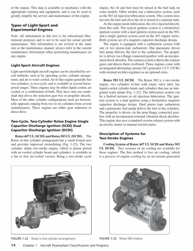
Rotax 447 UL (SCDI) and Rotax 503 UL (DCDI). The Rotax in-line cylinder arrangement has a small frontal area and provides improved streamlining (Fig. 1-22). The two cylinder, inline two-stroke engine, which is piston ported with air cooled cylinder heads and cylinders, is available in a fan or free air-cooled version. Being a two-stroke cycle
engine, the oil and fuel must be mixed in the fuel tank on some models. Other models use a lubrication system, such as the 503 oil injection lubrication system. This system does not mix the fuel and oil as the oil is stored in a separate tank.
As the engine needs lubrication, the oil is injected directly from this tank. The typical ignition system is a breakerless ignition system with a dual ignition system used on the 503, and a single ignition system used on the 447 engine series. Both systems are of a magneto capacitor discharge design.
The engine is equipped with a carburetion system with one or two piston-type carburetors. One pneumatic driven fuel pump delivers the fuel to the carburetors. The propel-ler is driven via a flange connected gearbox with an incorpo-rated shock absorber. The exhaust system collects the exhaust gases and directs them overboard. These engines come with an integrated alternating current (AC) generator (12 V 170 W) with external rectifier-regulator as an optional extra.
Rotax 582 UL DCDI. The Rotax 582 is a two-stroke engine, two cylinders in-line with rotary valve inlet, has liquid-cooled cylinder heads and cylinders that use an inte-grated water pump (Fig. 1-23). The lubrication system can be a fuel/oil mixture or oil injection lubrication. The igni-tion system is a dual ignition using a breakerless magneto capacitor discharge design. Dual piston type carburetors and a pneumatic fuel pump deliver the fuel to the cylinders. The propeller is driven via the prop flange connected gear-box with an incorporated torsional vibration shock absorber. This engine also uses a standard version exhaust system with an electric starter or manual rewind starter.
Description of Systems for Two-Stroke Engines
Cooling System of Rotax 447 UL SCDI and Rotax 503 UL DCDI. Two versions of air cooling are available for these engines. The first method is free air cooling, which is a process of engine cooling by an air-stream generated
Figure 1-22 Rotax in-line cylinder arrangement. Figure 1-23 Rotax 582 engine.
01_Kroes_Wild_Ch01_p001-028.indd 14 11/05/13 12:06 PM

Engine Design and Classification 15
by aircraft speed and propeller. The second is fan cooling, which is cooling by an air-stream generated by a fan perma-nently driven from the crankshaft via a V-belt.
Cooling System of the Rotax 582 UL DCDI. Engine cooling for the Rotax 582 is accomplished by liquid-cooled cylinders and cylinder heads (Fig. 1-24). The cooling sys-tem is in a two-circuit arrangement. The cooling liquid is supplied by an integrated pump in the engine through the cylinders and the cylinder head to the radiator. The cooling system has to be installed, so that vapor coming from the cylinders and the cylinder head can escape to the top via a hose, either into the water tank of the radiator or to an expan-sion chamber. The expansion tank is closed by a pressure cap (with excess pressure valve and return valve). As the temperature of the coolant rises, the excess pressure valve opens, and the coolant flows via a hose at atmospheric pres-sure to the transparent overflow bottle. When cooling down, the coolant is sucked back into the cooling circuit.
Lubrication Systems
Oil Injection Lubrication of Rotax 503 UL DCDI, and 582 UL DCDI. Generally, the smaller two-cycle engines are designed to run on a mixture of gasoline and 2% oil that is premixed in the fuel tank. The engines are planned to run on an oil-gasoline mixture of 1:50. Other engines use oil injection systems that use an oil pump driven by the crank-shaft via the pump gear that feeds the engine with the correct amount of fresh oil. The oil pump is a piston-type pump with a metering system. Diffuser jets in the intake inject pump supplied two-stroke oil with the exact proportioned quan-tity needed. The oil quantity is defined by the engine rota-tions per minute and the oil pump lever position. This lever is actuated via a cable connected to the throttle cable. The oil comes to the pump from an oil tank by gravity.
NOTE: In engines that use oil injection, the carburetors are fed with pure gasoline (no oil/gasoline mixture). The oil quantity in the oil tank must be checked before putting the engine into service as the oil is consumed during operation and needs to be replenished.
Electric System
The 503 UL DCDI, 582 UL DCDI engine types are equipped with a breakerless, SCDI unit with an integrated generator (Fig. 1-25). The 447 UL SCDI engine is equipped with a breakerless, SCDI unit with integrated generator. The igni-tion unit is completely free of maintenance and needs no external power supply. Two charging coils fitted on the gen-erator stator, independent from each other, each feed one ignition circuit. The energy supplied is stored in the ignition capacitor. At the moment of ignition, the external triggers supply an impulse to the control circuits and the ignition capacitors are discharged via the primary winding of the ignition coil. The secondary winding supplies the high volt-age for the ignition spark.
Fuel System
Due to higher lead content in aviation gas (AVGAS), opera-tion can cause wear and deposits in the combustion chamber to increase. Therefore, AVGAS should only be used if prob-lems are encountered with vapor lock or if the other fuel types are not available. Caution must be exercised to use only fuel suitable for the relevant climatic conditions, such as using winter fuel for summer operation.
Fuel/Oil Mixing Procedure. The following describes the process for fuel/oil mixing. Use a clean approved con-tainer of known volume. To help predilute the oil, pour a small amount of fuel into the container. Fill known amount
1
10
1113
6
128
3
14
7
9
4
2
5
1
2
3
4
5
6
7
8
9
10
11
12
14
13
Cooling liquid
Crankcase
Cylinder
Cylinder head
Water pump
Radiator
Hose from radiator to water pump
Hose from cylinder head to radiator
Radiator screw cap, with excess pressure valve and return valve
Temperature gauge for cooling water
Overflow hose
Overflow bottle
Bottle venting
Expansion tank
Cylinder head venting hose
Figure 1-24 Rotax 582 cooling system.
01_Kroes_Wild_Ch01_p001-028.indd 15 11/05/13 12:06 PM

16 Chapter 1 Aircraft Powerplant Classification and Progress
of oil (two-stroke oil ASTM/Coordinating European Council (CEC) standards, API-TC classification (e.g., Castrol TTS) mixing ratio 1:50 (2%), into container. Oil must be approved for air-cooled engines at 50:1 mixing ratio. Agitate slightly to dilute oil with gasoline. Add gasoline to obtain desired mix-ture ratio; use fine mesh screen. Replace the container cap and shake the container thoroughly. Then, using a funnel with a fine mesh screen to prevent the entry of water and foreign particles, transfer mixture from container into the fuel tank.
WARNING: To avoid electrostatic charging at refueling, use only metal containers and ground the aircraft in accor-dance with the grounding specifications.
Opposed Light-Sport, Experimental, and Certified Engines
Many certified engines are used with light-sport and experi-mental aircraft. Generally, cost is a big factor when consider-ing this type of powerplant. The certified engines tend to be much more costly than the noncertified engines, and are not ASTM approved.
Rotax 912/914
Figure 1-26 shows a typical four cylinder, four-stroke Rotax horizontally opposed engine. The opposed-type engine has two banks of cylinders directly opposite each other with a crankshaft in the center. The pistons of both cylinder banks are connected to the single crankshaft. The engine cylinder heads are both liquid cooled and air cooled; the air cool-ing is mostly used on the cylinder. It is generally mounted with the cylinders in a horizontal position. The opposed-type engine has a low weight to horsepower ratio, and its
narrow silhouette makes it ideal for horizontal installation on the aircraft wings (twin-engine applications). Another advantage is its low vibration characteristics. It is an ideal replacement for the Rotax 582 two-cylinder, two-stroke engine, which powers many of the existing light aircraft, as it is the same weight as the Rotax 582. These engines are ASTM approved for installation into light-sport category aircraft, with some models being FAA certified engines.
Description of Systems
Cooling System. The cooling system of the Rotax 914. shown in Fig. 1-27 is designed for liquid cooling of the
LA LC1
LC2 Spark plug
Spark plug
Spark plug
Spark plug
K
D
C
Electronic box 1
Electronic box 2
S
H1H2
C
S
H1H2
D
K
GEN
Yello
wP1P1
P2
GrayBlack/yellow
Green
Red/white
White
Black/yellow
Green
Red/white
White
Bla
ck/y
ello
w
Figure 1-25 Rotax 503 and 582 electrical system.
Figure 1-26 Typical four cylinder, four-stroke horizontally opposed engine.
01_Kroes_Wild_Ch01_p001-028.indd 16 11/05/13 12:06 PM

Engine Design and Classification 17
cylinder heads and ram-air cooling of the cylinders. The cooling system of the cylinder heads is a closed circuit with an expansion tank (Fig. 1-28). The coolant flow is forced by a water pump driven from the camshaft, from the radiator, to the cylinder heads. From the top of the cylinder heads, the coolant passes on to the expansion tank (1). Since the standard location of the radiator (2) is below engine level, the-expansion tank located on top of the engine allows for coolant expansion.
The expansion tank is closed by a pressure cap (3) (with excess pressure valve and return valve). As the tempera-ture of the coolant rises, the excess pressure valve opens and the coolant flows via a hose at atmospheric pressure to the transparent overflow bottle (4). When cooling down, the coolant is sucked back into the cooling circuit. Cool-ant temperatures are measured by means of temperature probes installed in the cylinder heads 2 and 3. The readings
are taken on measuring the hottest point of cylinder head depending on engine installation (Fig. 1-28).
Fuel System. The fuel flows from the tank (1) via a coarse filter/water trap (2) to the two electric fuel pumps (3) connected in series (Fig. 1-29). From the pumps, fuel passes on via the fuel pressure control (4) to the two carbure-tors (5). Parallel to each fuel pump is a separate check valve (6) installed via the return line (7) that allows surplus fuel to flow back to the fuel tank. Inspection for possible con-striction of diameter or obstruction must be accomplished to
Overflow bottle
Radiator
Expansion tank
1
2
3
4
Pressure cap
CO
DE
1
2
3
4
Cooling liquid
Expansion tank
Radiator
Expansion cap
Overflow bottle
Figure 1-27 Rotax 914 cooling system.
Figure 1-28 Water-cooled heads.
AUX MAIN
1
2
3 3
4
5
5
6 6
7C
OD
E
1
2
3
4
Fuel from tank
Filter/water trap
Electric fuel pumps
Fuel pressure control
Two carburetors
Check valve
Return line
5
6
7
Figure 1-29 Fuel system components.
01_Kroes_Wild_Ch01_p001-028.indd 17 11/05/13 12:07 PM

18 Chapter 1 Aircraft Powerplant Classification and Progress
avoid overflowing of fuel from the carburetors. The return line must not have any resistance to flow. The fuel pressure control ensures that the fuel pressure is always maintained approximately 0.25 bar [3.63 pounds per square inch (psi)] above the variable boost pressure in the airbox and thus, ensures proper operation of the carburetors.
Lubrication System. The Rotax 914 engine is provided with a dry, sump-forced lubrication system with a main oil pump with integrated pressure regulator and an additional suction pump (Fig. 1-30). The oil pumps are driven by the camshaft. The main oil pump draws oil from the oil tank (1) via the oil cooler (2) and forces it through the oil filter to the points of lubrication. It also lubricates the plain bearings of the turbocharger and the propeller governor. The surplus oil emerging from the points of lubrication accumulates on the bottom of crankcase and is forced back to the oil tank by the blow-by gases. The turbocharger is lubricated via a sepa-rate oil line (from the main oil pump). The oil emerging from the lower placed turbocharger collects in the oil sump by a separate pump and is pumped back to the oil tank via the oil line (3). The oil circuit is vented via bore (5) in the oil tank. There is an oil temperature sensor in the oil pump flange for reading of the oil inlet temperature.
Electric System. The Rotax 914 engine is equipped with a dual ignition unit that uses a breakerless, capacitor discharge design with an integrated generator (Fig. 1-31). The ignition unit is completely free of maintenance and needs no external power supply. Two independent charging coils (1) located on the generator stator supply one ignition circuit each. The energy is stored in capacitors of the elec-tronic modules (2). At the moment of ignition, two each of
the four external trigger coils (3) actuate the discharge of the capacitors via the primary circuit of the dual ignition coils (4). The firing order is as follows: 1-4-2-3. The fifth trigger coil (5) is used to provide the revolution counter signal.
Turbocharger and Control System. The Rotax 914 engine is equipped with an exhaust gas turbocharger mak-ing use of the energy in the exhaust gas for compression of the intake air or for providing boost pressure to the induction system. The boost pressure in the induction system (airbox) is controlled by means of an electronically controlled valve (wastegate) in the exhaust gas turbine. The wastegate regu-lates the speed of the turbocharger and consequently the boost pressure in the induction system. The required nominal boost pressure in the induction system is determined by the throttle position sensor mounted on the carburetor 2/4. The sensor’s transmitted position is linear 0 to 115%, corresponding to a throttle position from idle to full power (Fig. 1-32). For cor-relation between throttle position and nominal boost pressure in the induction, refer to Fig. 1-33. As shown in the diagram, with the throttle position at 108–110% results in a rapid rise of nominal boost pressure.
To avoid unstable boost, the throttle should be moved smoothly through this area either to full power (115%) or at a reduced power setting to maximum continuous power. In this range (108–110% throttle position), small changes in throttle position have a big effect on engine performance and speed. These changes are not apparent to the pilot from the throttle lever position. The exact setting for a specific performance is virtually impossible in this range and has to be prevented, as it might cause control fluctuations or surging. Besides the throttle position, overspeeding of the
1
4
3
5
2
CO
DE
1
2
3
4
Oil lubricant
Oil tank
Oil cooler
Oil line
Pressure line
Oil circuit vent bore5
Figure 1-30 Lubrication system.
01_Kroes_Wild_Ch01_p001-028.indd 18 11/05/13 12:07 PM

Engine Design and Classification 19
engine and too high intake air temperature have an effect on the nominal boost pressure. If one of the stated factors exceeds the specified limits, the boost pressure is automati-cally reduced, thus protecting the engine against over boost and detonation.
The turbo control unit (TCU) is furnished with output connections for an external red boost lamp and an orange caution lamp for indications of the functioning of the TCU. When switching on the voltage supply, the two lamps are
automatically subject to a function test. Both lamps illumi-nate for one to two seconds, then they extinguish. If they do not, a check per the engine maintenance manual is necessary. If the orange caution lamp is not illuminated, then this sig-nals that TCU is ready for operation. If the lamp is blinking, this indicates a malfunction of the TCU or its periphery sys-tems. Exceeding of the admissible boost pressure activates and illuminates the red boost lamp continuously. The TCU registers the time of full throttle operation (boost pressure). Full throttle operation for longer than 5 minutes, with the red boost light illuminated, makes the red boost lamp start blink-ing. The red boost lamp helps the pilot to avoid full power operation for longer than 5 minutes or the engine could be subject to thermal and mechanical overstress.
HKS 700T Engine
The HKS 700T engine is a four-stroke, two-cylinder turbo-charged engine equipped, with an intercooler (Fig. 1-34).
3
B3/4
A1/2
A3/4
B1/2
Ignition Circult B
Ignition Circult A
2
2
3
3
3
4
4
4
4
51
CO
DE
1
2
3
4
Charging coils
Capacitors
Four external trigger coils
Dual ignition coils
Fifth trigger coil5
Figure 1-31 Electric system.
115%
100%0%
Figure 1-32 Turbocharger control system throttle range and position.
0900
1,000
1,100
1,200
1,300
1,400
hPa"Hg
1,500
10 20 30 40 50 60 70 80 90 100 110115%
283032343638
4240
4446
Figure 1-33 Correlation between throttle position and nominal boost pressure.
01_Kroes_Wild_Ch01_p001-028.indd 19 11/05/13 12:07 PM

20 Chapter 1 Aircraft Powerplant Classification and Progress
The horizontally opposed cylinders house four valves per cylinder, with a piston displacement of 709 cc. It uses an electronic control fuel injection system. A reduction gearbox is used to drive the propeller flange at a speed reduction ratio of 2.13 to 1. The engine is rated at 77 hp continuous and 80 hp takeoff (3 minutes) at 4900 and 5300 RPM, respec-tively. A total, engine weight of 126 pounds provides a good power to weight ratio. The 700T has a TBO of 500 hours.
Jabiru Light-Sport Engines
Jabiru engines are designed to be manufactured using the lat-est manufacturing techniques (Fig. 1-35). All Jabiru engines are manufactured, assembled, and ran on a Dynometer, then calibrated before delivery. The crankcase halves, cylinder heads, crankshaft, starter motor housings, gearbox cover (the gearbox powers the distributor rotors), together with many smaller components are machined from solid material.
Figure 1-34 HKS 700T engine.
The sump (oil pan) is the only casting. The cylinders are machined from bar 4140 chrome molybdenum alloy steel, with the pistons running directly in the steel bores. The crankshaft is also machined from 4140 chrome molybde-num alloy steel, the journals of which are precision ground prior to being Magnaflux inspected. The camshaft is manu-factured from 4140 chrome molybdenum alloy steel with nitrided journals and cams.
The propeller is direct crankshaft driven and does not use a reduction gearbox. This facilitates its lightweight design and keeps maintenance costs to a minimum. The crankshaft features a removable propeller flange that enables the easy replacement of the front crankshaft seal and provides for a propeller shaft extension to be fitted, should this be required for particular applications. Cylin-der heads are machined from a solid aluminum billet that is purchased directly from one company, thereby providing a substantive quality control trail to the material source. Connecting rods are machined from 4140 alloy steel and the 45 millimeters big end bearings are of the automotive slipper type. The ignition coils are sourced from outside suppliers and are modified by Jabiru for their own particu-lar application.
An integral alternator provides AC rectification for bat-tery charging and electrical accessories. The alternator is attached to the flywheel and is driven directly by the crank-shaft. The ignition system is a transistorized electronic sys-tem; two fixed coils mounted adjacent to the flywheel are energized by magnets attached to the flywheel. The passing of the coils by the magnets creates the high-voltage cur-rent, that is transmitted by high tension leads to the center post of two automotive type distributors, which are simply rotors and caps, before distribution to automotive spark plugs (two in the top of each cylinder head). The ignition system is fixed timing and, therefore, removes the need for timing adjustment. It is suppressed to prevent radio interference.
The ignition system is fully redundant, self-generating, and does not depend on battery power. The crankshaft is designed with a double bearing at the propeller flange end and a main bearing between each big end. Thrust bearings are located fore and aft of the front double bearing, allowing either tractor or pusher installation. Pistons are remachined to include a piston pin, circlip, and groove. They are all fit-ted with three rings, the top rings being cast iron to comple-ment the chrome molybdenum cylinder bores. Valves are 7 mm (stem diameter) and are manufactured specifically for the Jabiru engine. The valve drive train includes push-rods from the camshaft from the camshaft followers to valve rockers. The valves are Computer Numerical Control (CNC) machined from steel billet, induction hardened, pol-ished on contact surfaces, and mounted on a shaft through Teflon coated bronze-steel bush. Valve guides are manufac-tured from aluminum/bronze. Replaceable valve seats are of nickel steel and are shrunk into the aluminum cylinder heads. The valve train is lubricated from the oil gallery. Engines use hydraulic lifters that automatically adjust valve clearance. An internal gear pump is driven directly by the
Figure 1-35 Jabiru engines.
01_Kroes_Wild_Ch01_p001-028.indd 20 11/05/13 12:07 PM

Engine Design and Classification 21
camshaft and provides engine lubrication via an oil circuit that includes an automotive spin-on filter, oil cooler, and built-in relief valve.
The standard engines are supplied with two ram-air cooling ducts, that have been developed by Jabiru to facil-itate the cooling of the engine by directing air from the propeller to the critical areas of the engine, particularly the cylinder heads and barrels. The use of these ducts remove the need to design and manufacture baffles and the establishment of a plenum chamber, which is the traditional method of cooling air-cooled, aircraft engines. The fact that these baffles and plenum chamber are not required also ensures a cleaner engine installation, which in turn facili-tates maintenance and inspection of the engine and engine components.
The engine is fined with a 1.5 kW starter motor that is also manufactured by Jabiru and provides very effec-tive starting. The engine has very low vibration level; however, it is also supported by four large rubber shock mounts attached to the engine mounts at the rear of the engine. The fuel induction system uses a pressure com-pensating carburetor. Following the carburetor, the fuel/air mixture is drawn through a swept plenum chamber bolted to the sump casting, in which the mixture is warmed prior to entering short induction tubes attached to the cylinder heads.
An effective stainless steel exhaust and muffler system is fitted as standard equipment ensuring very quiet opera-tions. For owners wanting to fit vacuum instruments to their aircraft, the Jabiru engines are designed with a vac-uum pump drive direct mounted through a coupling on the rear of the crankshaft.
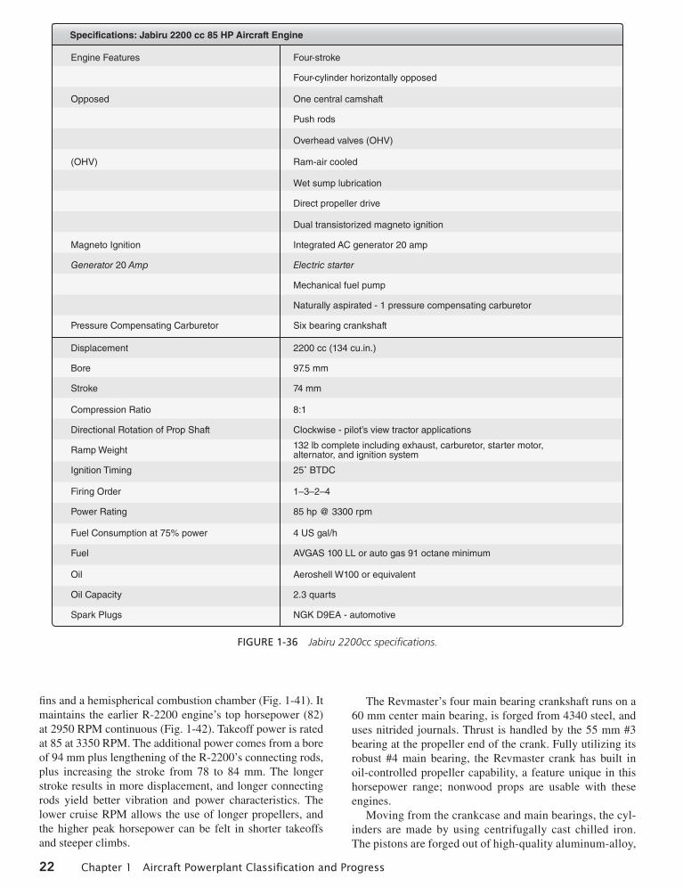
Jabiru 2200 Aircraft Engine. The Jabiru 2200 cc aircraft engine is a four-cylinder, four-stroke horizontally opposed air-cooled engine. At 132 pounds [60kgs] installed weight, it is one of the lightest four-cylinder, four-stroke aircraft engines. Small overall dimensions give it a small frontal area width (23.46 in, 596 mm) that makes it a good engine for tractor applications. The Jabiru engine is designed for either tractor or pusher installation. The Jabiru engine specifications are listed in Fig. 1-36.
The Jabiru 3300 (120 hp) engine features (Fig. 1-37):
· 4-stroke· 3300 cc engine (200 in3)· 6-cylinder horizontally opposed· 1 central camshaft· Fully machined aluminum-alloy crankcase· Overhead valves (OHV)—push rod operated· Ram-air cooled· Wet sump lubrication—4 liter capacity· Direct propeller drive· Dual transistorized magneto ignition· Integrated AC generator· Electric starter· Mechanical fuel pump· Naturally aspirated—1 pressure compensation carburetor
Aeromax Aviation 100 (IFB) Aircraft Engine. Aero-max Aviation produces a version of a 100-hp engine. The engine features a special made integral front bear-ing (Fig. 1-38). The engine uses an integral permanent magnet 35-amp alternator, lightweight starter, and dual ignition. The compact alternator and starter allow for a streamlined and aerodynamic cowl which improves the fuel efficiency of an experimental aircraft. The Aeromax aircraft engine is an opposed six-cylinder, air-cooled, and direct drive. Being a six-cylinder engine, it has smooth operation. The Aeromax engines are known for their heat dissipation qualities, provided the proper amount of cool-ing air is provided.
It features a crank extension supported by a massive integral front bearing (IFB) and bearing housing. These engines start out as a GM Corvair automobile core engine. These basic core engines are disassembled and each com-ponent that is reused is refurbished and remanufactured. The crankshaft in the Areomax 100 IFB aircraft engine is thoroughly inspected, including a magnaflux inspection. After ensuring the crank is free of any defects, it is extended by mounting the crank extension hub on its front. Then, the crank is ground true, with all five bearings’ surfaces (four original and the new-extended crank’s front bearing), being true to each other and perpendicular to the crank’s prop flange (Fig. 1-39).
All radiuses are smooth with no sharp corners where stress could concentrate. Every crankshaft is nitrated, which is a heat/chemical process that hardens the crank surfaces. The crank reinforcement coupled with the IFB is required to counter the additional dynamic and bending loads introduced on the crank in an aircraft application. The engine case is totally refurbished and checked for wear. Any studs or bolts that show wear are replaced. The engine heads are machined to proper specifications and all new valves, guides, and valve train components are installed. A three-angle valve grind and lapping ensure a good valve seal.
Once the engine is assembled, it is installed on a test stand, prelubricated, and inspected. The engine is, then, run sev-eral times for a total of two hours. The engine is carefully inspected after each run to ensure that it is in excellent operat-ing condition. At the end of test running the engine, the oil fil-ter is removed and cut for inspection. Its internal condition is recorded. This process is documented and kept on file for each individual engine. Once the engine’s proper performance is assured, it is removed and packaged in a custom built crate for shipping. Each engine is shipped with its engine service and operations manual. This manual contains information pertain-ing to installation, break–in, testing, tune-up, troubleshooting, repair, and inspection procedures. The specifications for the Aeromax 100 engine are outlined in Fig. 1-40.
Direct Drive VW Engines
Revmaster R-2300 Engine
The Revmaster R-2300 engine maintains Revmaster’s sys-tems and parts, including its RM-049 heads that feature large
01_Kroes_Wild_Ch01_p001-028.indd 21 11/05/13 12:07 PM
22 Chapter 1 Aircraft Powerplant Classification and Progress
Displacement
Bore
Stroke
Compression Ratio
Directional Rotation of Prop Shaft
Ramp Weight
Ignition Timing
Firing Order
Power Rating
Fuel Consumption at 75% power
Fuel
Oil
Oil Capacity
Spark Plugs
Engine Features
Opposed
(OHV)
Magneto Ignition
Generator 20 Amp
Pressure Compensating Carburetor
Four-stroke
Four-cylinder horizontally opposed
One central camshaft
Push rods
Overhead valves (OHV)
Ram-air cooled
Wet sump lubrication
Direct propeller drive
Dual transistorized magneto ignition
Integrated AC generator 20 amp
Electric starter
Mechanical fuel pump
Naturally aspirated - 1 pressure compensating carburetor
Six bearing crankshaft
2200 cc (134 cu.in.)
97.5 mm
74 mm
8:1
Clockwise - pilot’s view tractor applications
132 lb complete including exhaust, carburetor, starter motor, alternator, and ignition system
25˚ BTDC
1–3–2–4
85 hp @ 3300 rpm
4 US gal/h
AVGAS 100 LL or auto gas 91 octane minimum
Aeroshell W100 or equivalent
2.3 quarts
NGK D9EA - automotive
Specifications: Jabiru 2200 cc 85 HP Aircraft Engine
Figure 1-36 Jabiru 2200cc specifications.
fins and a hemispherical combustion chamber (Fig. 1-41). It maintains the earlier R-2200 engine’s top horsepower (82) at 2950 RPM continuous (Fig. 1-42). Takeoff power is rated at 85 at 3350 RPM. The additional power comes from a bore of 94 mm plus lengthening of the R-2200’s connecting rods, plus increasing the stroke from 78 to 84 mm. The longer stroke results in more displacement, and longer connecting rods yield better vibration and power characteristics. The lower cruise RPM allows the use of longer propellers, and the higher peak horsepower can be felt in shorter takeoffs and steeper climbs.
The Revmaster’s four main bearing crankshaft runs on a 60 mm center main bearing, is forged from 4340 steel, and uses nitrided journals. Thrust is handled by the 55 mm #3 bearing at the propeller end of the crank. Fully utilizing its robust #4 main bearing, the Revmaster crank has built in oil-controlled propeller capability, a feature unique in this horsepower range; nonwood props are usable with these engines.
Moving from the crankcase and main bearings, the cyl-inders are made by using centrifugally cast chilled iron. The pistons are forged out of high-quality aluminum-alloy,
01_Kroes_Wild_Ch01_p001-028.indd 22 11/05/13 12:07 PM

Engine Design and Classification 23
machined and balanced in a set of four. There are two sizes of pistons, 92 mm and 94 mm, designed to be compat-ible with a 78 to 82 mm stroke crankshafts. The cylinder set also contains piston rings, wrist pins, and locks. The direct-drive R-2300 uses a dual CDI ignition with eight coil spark to eight spark plugs, dual 20-amp alternators, oil cooler, and its proprietary Rev-Flo carburetor, while introducing the longer cylinders that do not require spac-ers. The automotive-based bearings, valves, valve springs, and piston rings (among others) make rebuilds easy and inexpensive.
great Plains Aircraft Volkswagen (VW) Conversions
Great Plains Aircraft is one company that offers several con-figurations of the Volkswagen (VW) aircraft engine conver-sion. One very popular model is the front drive long block kits that offer a four-cycle, four-cylinder opposed engine with horsepower ranges from approximately 60-100 (Fig. 1-43). The long block engine kits, which are the complete engine kits that are assembled, in the field or can be shipped com-pletely assembled, are available from 1600 cc up through 2276 cc. All the engine kits are built from proven time tested
Displacement
Bore
Stroke
Aircraft Engine
Compression Ratio
Directional Rotation of Prop Shaft
Ramp Weight
Ignition Timing
Firing order
Power Rating
Fuel Consumption at 75% power
Fuel
Oil
Oil Capacity
Spark Plugs
3300 cc (202cu.in.)
97.5 mm (3.838")
74 mm (2.913")
Jabiru 3300cc 120 hp
8:1
Clockwise - Pilot's view tractor applications
178 lbs (81 kg) complete including exhaust, carburetor, starter motor, alternator and ignition system
25° BTDC fixed timing
1–4–5–2–3–6
120 hp @ 3300 rpm
26 l/hr (6.87 US gal/h)
AVGAS 100 LL or auto gas 91 octane minimum
Aeroshell W100 or equivalent
3.51 (3.69 quarts)
NGK D9EA - automotive
Jabiru 3300 cc Aircraft Engine
Figure 1-37 Jabiru 3300 cc aircraft engine.
Figure 1-38 Aeromax direct drive, air-cooled, six-cylinder engine.
Figure 1-39 Front-end bearing on the 1000 IFB engine.
01_Kroes_Wild_Ch01_p001-028.indd 23 11/05/13 12:07 PM

24 Chapter 1 Aircraft Powerplant Classification and Progress
components and are shipped with a Type One VW Engine Assembly Manual. This manual was written by the manu-facturer, specifically for the assembly of their engine kits. Also included are how to determine service and maintenance procedures and many tips on how to set up and operate the engine correctly. The crankshaft used in the 2180 to 2276 cc engines is a 82 mm crankshaft made from a forged billet of E4340 steel, machined and magnafluxed twice. The end of the crankshaft features a 12-inch fine thread versus a 20 mm thread found on the standard automotive crank.
Teledyne Continental 0-200 Engine
The 0-200 Series engine has become a popular engine for use in light-sport aircraft. The 0-200-A/B is a four-cylinder, carbureted engine producing 100 brake hp and has a
Power Output: 100 hp continuous at 3200 rpm
Displacement: 2.7 L
Compression: 9:1
Weight: 210 lb
Direct Drive
Rear Light weight. Starter and 45 amp alternator
Counterclockwise rotation
Harmonic balancer
Remanufactured case
Remanufactured heads with new guides, valves, valve train, intake
Remanufactured cylinders
New light weight aluminum cylinder - optional
New high torque cam
New CNC prop hub and safety shaft
New Aeromax top cover and data plate
Air cooled
Six cylinders
Dual ignition–single plug
Normally aspirated
CHT max: 475 F
New forged pistons
Balanced and nitrated crank shaft
New hydraulic lifters
New main/rod bearings
New all replaceable parts
New spark plug wiring harness
Remanufactured dual ignition distributor with new points set and electronic module
New oil pump
New oil pan
Engine service manual
Aeromax 100 Engine Specifications
Figure 1-40 Aeromax 100 engine specifications.
Figure 1-41 Revmaster R-2300 engine.
Figure 1-42 Hemispherical combustion chamber within the Revmaster R-2300 Heads.
Figure 1-43 Great Plain’s Volkswagen conversion.
01_Kroes_Wild_Ch01_p001-028.indd 24 11/05/13 12:07 PM
Engine Design and Classification 25
crankshaft speed of 2750 RPM (Fig. 1-44). The engine has horizontally opposed air-cooled cylinders. The engine cyl-inders have an overhead valve design with updraft intake inlets and downdraft exhaust outlets mounted on the bottom of the cylinder. The 0-200-A/B engines have a 201 cubic inch displacement achieved by using a cylinder design with a 4.06-inch diameter bore and a 3.88-inch stroke. The dry weight of the engine is 170.18 pounds without acces-sories. The weight of the engine with installed accessories is approximately 215 pounds. The engine is provided with
four integral rear engine mounts. A crankcase breather port is located on the 1-3 side of the crankcase forward of the number 3 cylinder. The engine lubrication system is a wet sump, high-pressure oil system. The engine lubrication sys-tem includes the internal engine-driven pressure oil pump, oil pressure relief valve, pressure oil screen mounted on the rear of the accessory case and pressure instrumentation. A fitting is provided at the 1-3 side of the crankcase for oil pressure measurement. The oil sump capacity is six quarts maximum. The 0-200-A/B induction system consists of an updraft intake manifold with the air intake and throttle mounted below the engine. Engine manifold pressure is measured at a port located on the 2-4 side of the intake air manifold. The 0-200-A/B is equipped with a carburetor that meters fuel flow as the flightdeck throttle and mixture con-trols are changed.
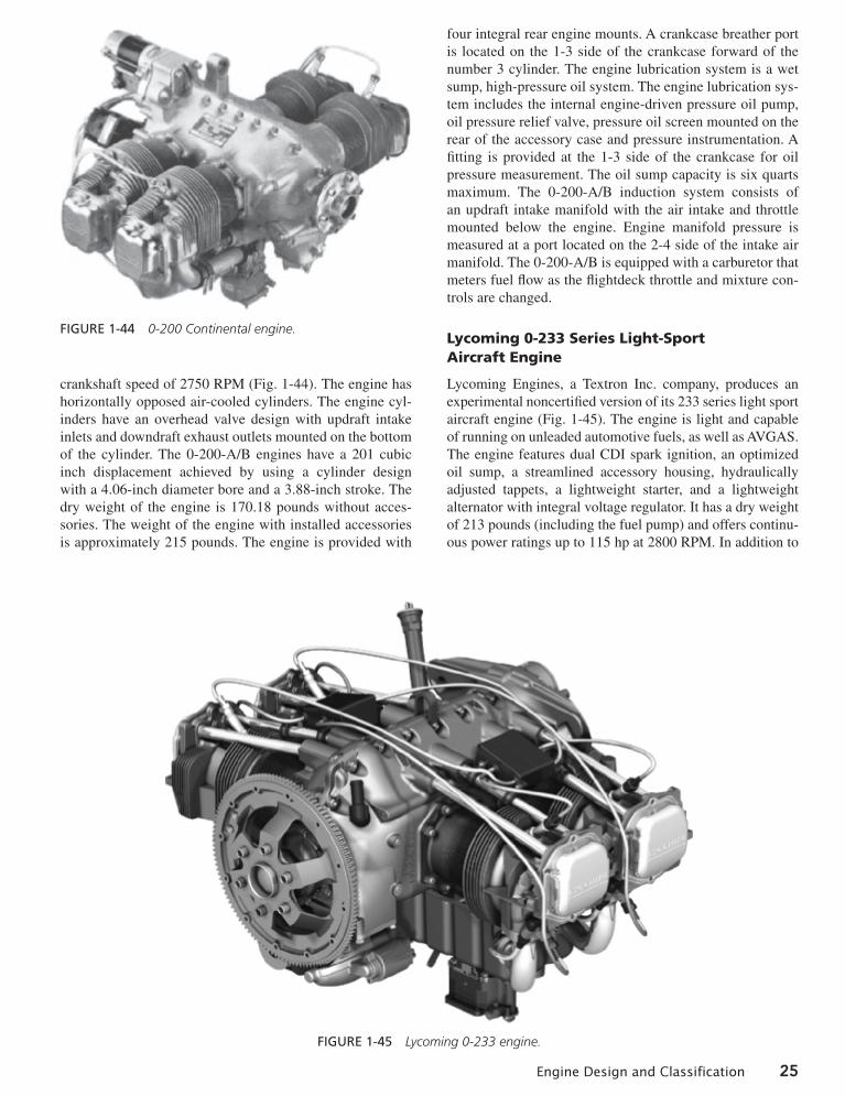
Lycoming 0-233 Series Light-Sport Aircraft Engine
Lycoming Engines, a Textron Inc. company, produces an experimental noncertified version of its 233 series light sport aircraft engine (Fig. 1-45). The engine is light and capable of running on unleaded automotive fuels, as well as AVGAS. The engine features dual CDI spark ignition, an optimized oil sump, a streamlined accessory housing, hydraulically adjusted tappets, a lightweight starter, and a lightweight alternator with integral voltage regulator. It has a dry weight of 213 pounds (including the fuel pump) and offers continu-ous power ratings up to 115 hp at 2800 RPM. In addition to
Figure 1-44 0-200 Continental engine.
Figure 1-45 Lycoming 0-233 engine.
01_Kroes_Wild_Ch01_p001-028.indd 25 11/05/13 12:07 PM

26 Chapter 1 Aircraft Powerplant Classification and Progress
its multi-gasoline fuel capability, it has proven to be very reliable with a TBO of 2400 hours. The initial standard ver-sion of the engine is carbureted, but fuel injected configura-tions of the engine are also available.
The Porsche PFM 3200 Aircraft Engine
Porsche has received Federal Aviation Administration (FAA) certification for its PFM 3200 engine, which is being supplemental type certificated for use in general aviation fixed- and rotary-wing aircraft in the 200- to 300-hp [149.14- to 223.71-kW] range. The engine is currently being pro-duced in two versions, a 209-hp [155.85-kW] unit designed to burn autogas and avgas interchangeably and a 217-hp [161.82-kW] model for avgas only. Higher-horsepower versions are under development. The Porsche PFM 3200 engine is illustrated in Fig. 1-46.
The PFM 3200 engine is a derivative of the Porsche 911 sports-car engine. The 911 engine is a lightweight six-cylinder horizontally opposed air-cooled engine. The 3200 engine incorporates many technologically advanced concepts such as a single power lever that replaces the throttle; mixture, and propeller controls. The pilot operates the power lever much as the driver of a car operates the accelerator pedal. When the power lever is set, the fuel mixture and propeller speed adjust automatically to ensure maximum efficiency at all altitudes and power settings. The engine has a dual ignition system with variable ignition timing. The correct timing is deter-mined by the running speed, intake air temperature, and abso-lute intake manifold pressure. An automatic fuel injection system provides the correct air-fuel mixture at all altitudes. The engine is cooled by an engine-driven fan that provides cooling air in direct proportion to the power output.
Jet Propulsion History
During World War II, the demand for increased speed mid power expedited the progress which was already taking place in the development of jet propulsion powerplants. As a result of the impetus given by the requirements of the War and Navy departments in the United States and by similar demands on the part of Great Britain, engineers in England and the United States designed, manufactured, and tested in flight an amazing variety of jet propulsion powerplants. Note also that the Gentian government was not trailing behind in the jet propulsion race, because the first flight by an airplane powered with a true jet engine was made in Germany on August 27, 1939. The airplane was a Heinkel He 178 and was powered by a Heinkel HeS 3B turbojet engine.
The first practical turbojet engines in England and the United States evolved from the work of Sir Prank Whittle in England. The success of experiments with this engine led to the development and manufacture of the Whittle W1 engine. Under agreement with the British government, the United States was authorized to manufacture an engine of a design similar to the W1. The General Electric Company was given a contract to build the engine because of its extensive experi-ence with turbine manufacture and with the development of turbosuperchargers used for military aircraft in World War II. Accordingly, the General Electric GE I-A engine was built and successfully flown in a Bell XP-59A airplane.
The successful development of jet propulsion is beyond question the greatest single advance in the history of aviation since the Wright brothers made their first flight. The speed of aircraft has increased from below Mach 1, the speed of sound, to speeds of more than Mach 4. Commercial airliners now operate at more than 600 miles per hour (mph) [965.6 kilometers per hour (km/h)] rather than at speeds of around 350 mph [563.26 km/h], which is usually about the maxi-mum for conventional propeller-driven airliners.
gas-Turbine Engine Progress
The gas-turbine engine can be used as a turbojet engine (thrust developed by exhaust gases alone), a turbofan engine (thrust developed by a combination of exhaust gases and fan air), a turboprop engine (in which a gas-turbine engine turns a gearbox for driving propellers), and a turboshaft engine (which drives helicopter rotors). Small gas-turbine engines called APU’s (auxiliary power units) have been developed to supply transport-category aircraft with electrical and pneu-matic power. Although these units can be used both on the ground and in the air, they are mainly used on the ground.
Gas-turbine engines are used for propulsion in many dif-ferent types of aircraft. These aircraft include airliners, busi-ness aircraft, training aircraft, helicopters, and agricultural aircraft. During the development of the gas-turbine engine, many challenges have faced designers and engineers. Some of the concerns which designers are constantly striving to improve on gas-turbine engines are performance, sound levels, fuel efficiency, ease of maintenance, dependability, and reliability. Many different types of gas-turbine engines have been developed to meet the overall propulsion needs Figure 1-46 Porsche PFM 3200 engine
01_Kroes_Wild_Ch01_p001-028.indd 26 11/05/13 12:07 PM

Review Questions 27
of the aviation community. An example of an engine which incorporates many of the learned technologies needed to provide excellent fuel consumption, low emissions and many of the characteristics mentioned earlier, is the GE90, shown in Fig. 1-47. This engine is a high bypass turbofan engine which incorporates a fan with a diameter in excess of 10 ft [3 m] and has a thrust range of 72 000 to over 100 000 lb [32 660 to 43 090 kg] of takeoff thrust.
The largest increase in turbine technology has been the use of electronic engine control systems for full authority engine control. This also allowed for full integration with air-craft monitoring systems. The huge amount of thrust devel-oped by each engine (well over 100 000 lbs of thrust) has allowed for heavier aircraft with fewer engines. The engine electronic control system automatically monitors and con-trols several separate systems during engine operation. Some examples of these systems are engine starting, relighting following flame-out detection, total control of fuel control as per pilot input, variable inlet guide vane/variable stator vanes position, compressor bleed valves, engine oil/fuel heat management, gearbox cooling airflow, turbine case cool-ing airflow, high-pressure valve for aircraft cabin air, probe heater control, thrust reverser, and turbine overheat data.
These systems and more will be explained in detail in the chapters on turbine engines later in this text.
REVIEW QuESTIOnS
1. List the advantages of the in-line engine. 2. Describe the difference between upright-V-type
and inverted-V-type engines. 3. What type of reciprocating engine design pro-
vides the best power-to-weight ratio? 4. List the advantages of the opposed-type engine
design. 5. Conventional piston engines are classified accord-
ing to what characteristics? 6. Name four common engine classifications by cyl-
inder arrangement. 7. The letter “O” in an engine designation is used to
denote what? 8. The greatest single advance in aircraft propulsion
was the development of what type of engine? 9. What does the power lever on the Porsche engine
operate?
Figure 1-47 GE90 High Bypass Propulsion system (General Electric).
01_Kroes_Wild_Ch01_p001-028.indd 27 11/05/13 12:07 PM

01_Kroes_Wild_Ch01_p001-028.indd 28 11/05/13 12:07 PM