airfield damage repair - wordpress.com
TRANSCRIPT

this document downloaded from...
chet-aero.com
the wings of flight in an age
of adventure
Use of this document subject to the terms and conditions as stated on the website.
for more downloads visit our other sites Positive Infinity and vulcanhammer.net

UFC 3-270-0730 JUNE 2003DRAFT
UNIFIED FACILITIES CRITERIA (UFC)
AIRFIELD DAMAGE REPAIR
APPROVED FOR PUBLIC RELEASE: DISTRIBUTION UNLIMITED
UFC 3-270-0730 JUNE 2003DRAFT
UNIFIED FACILITIES CRITERIA (UFC)
CRITERIA FORMAT STANDARD
Any copyrighted material included in this UFC is identified at its point of use.Use of the copyrighted material apart from this UFC must have the permission of thecopyright holder.
U.S. ARMY CORPS OF ENGINEERS (Preparing Activity)
NAVAL FACILITIES ENGINEERING COMMAND
AIR FORCE CIVIL ENGINEER SUPPORT AGENCY
Record of Changes (changes are indicated by \1\ ... /1/)
Change No. Date Location

UFC 3-270-0730 JUNE 2003DRAFT
FOREWORD
The Unified Facilities Criteria (UFC) system is prescribed by MIL-STD 3007, provides planning,design, construction, sustaintment, restoration, and modernization criteria, and applies to theMilitary Departments, the Defense Agencies, and the Department of Defense (DoD) FieldActivities in accordance with USD(AT&L) Memorandum dated 29 May 2002. UFC will be used forall DoD projects and work for other customers where appropriate. All construction outside ofthe United States is also governed by Status of Forces Agreements (SOFA), Host Nation FundedConstruction Agreements (HNFA), and, in some instances, Bilateral Infrastructure Agreements(BIA). Therefore, the acquisition team must ensure compliance with the more stringent of theUFC, the SOFA, the HNFA, and the BIA, as applicable.
UFC are living documents and will be periodically reviewed, updated, and made available tousers as part of the Services’ responsibility for providing technical criteria for militaryconstruction. Headquarters, U.S. Army Corps of Engineers (HQUSACE), Naval FacilitiesEngineering Command (NAVFAC), and Air Force Civil Engineer Support Agency (AFCESA) areresponsible for administration of the UFC system. Defense agencies should contact thepreparing service for document interpretation and improvements. Technical content of UFC is theresponsibility of the cognizant DoD working group. Recommended changes with supportingrationale should be sent to the respective service proponent office by the following electronicform: Criteria Change Request (CCR). The form is also accessible from the Internet sites listedbelow.
UFC are effective upon issuance and are distributed only in electronic media from the followingsources:
• Unified Facilities Criteria (UFC) Index http://65.204.17.188//report/doc_ufc.html.• USACE TECHINFO Internet site http://www.hnd.usace.army.mil/techinfo/index.htm.• NAVFAC Engineering Innovation and Criteria Office Internet site http://criteria.navfac.navy.mil.• Construction Criteria Base (CCB) system maintained by the National Institute of Building
Sciences at Internet site http://www.nibs.org/ccb.
Hard copies of UFC printed from electronic media should be checked against the currentelectronic version prior to use to ensure that they are current.
AUTHORIZED BY:
______________________________________Dwight A. Beranek, P.E.Chief, Engineering and Construction DivisionU.S. Army Corps of Engineers
___________________________________Dr. James W. Wright, P.E.Chief EngineerNaval Facilities Engineering Command
______________________________________Kathleen I. Ferguson, P.E.The Deputy Civil EngineerDCS/Installations & LogisticsDepartment of the Air Force
___________________________________Frank LaneDirector of Analysis & InvestmentDeputy Under Secretary of Defense for Installations and EnvironmentDepartment of Defense

UFC 3-270-0730 JUNE 2003
i
DRAFTCONTENTS
PageCHAPTER 1 INTRODUCTION
Paragraph 1-1 PURPOSE AND SCOPE................................................................ 11-2 APPLICATION.................................................................................. 1
CHAPTER 2 PAVEMENT REPAIR CRITERIA
Paragraph 2-1 DESCRIPTION OF ENGINEER ACTIVITIES .............................. 22-2 BOMB DAMAGE ASSESSMENT ................................................... 22-3 SELECTION OF THE MOS............................................................ 22-4 SAFING AND DISPOSAL OF EXPLOSIVE ORDNANCE .......... 32-5 BOMB DAMAGE REPAIR .............................................................. 32-6 DEFINITIONS................................................................................... 32-6.1 Spalls................................................................................................ 32-6.2 Craters.............................................................................................. 32-7 EXPEDIENT REPAIR...................................................................... 42-8 SUSTAINMENT REPAIR................................................................ 42-9 PERMANENT REPAIR ................................................................... 52-10 SELECTION OF REPAIR METHOD............................................. 52-11 REPAIR QUALITY CRITERIA (RQC)............................................ 62-12 REPAIR EVALUATION METHODS............................................... 72-12.1 Acceptance Criteria ........................................................................ 72-12.2 Airfield Certification......................................................................... 9
CHAPTER 3 SPALL REPAIR
Paragraph 3-1 DEFINITION OF SPALL.................................................................. 103-2 REPAIR CONCEPT ........................................................................ 103-2.1 Purpose............................................................................................ 103-2.2 Concerns.......................................................................................... 103-3 MATERIALS...................................................................................... 103-3.1 Conventional Cement/Grout......................................................... 103-3.2 Cold Mix Products........................................................................... 113-3.3 Proprietary Products....................................................................... 113-3.4 Technical Representatives........................................................... 113-4 SPALL REPAIR/ACCEPTANCE PROCEDURES...................... 113-5 SPALL REPAIR ACCEPTANCE CRITERIA ................................ 12
CHAPTER 4 EXPEDIENT REPAIR METHODS
Paragraph 4-1 EXPEDIENT REPAIR CONCEPT................................................. 134-1.1 Purpose............................................................................................ 134-1.2 Assumptions ................................................................................... 13

UFC 3-270-0730 JUNE 2003
ii
DRAFT4-2 SELECTION OF REPAIR METHOD............................................. 134-2.1 Aircraft Type and Load ................................................................... 134-2.2 Available Material............................................................................ 134-2.3 Available Equipment ...................................................................... 134-2.4 Repair Quality Criteria (RQC)....................................................... 134-2.5 Existing Pavement Structure......................................................... 134-2.6 Time Constraints............................................................................ 134-2.7 Repair Crew Capability/Equipment/Manpower......................... 144-3 CRUSHED STONE REPAIR......................................................... 144-3.1 Materials........................................................................................... 144-3.2 Types of Repair Methods .............................................................. 154-3.3 Procedures ...................................................................................... 164-4 SAND-GRID REPAIR...................................................................... 184-5 FOREIGN OBJECT DAMAGE (FOD) COVERS.......................... 204-5.1 Army FOD Cover Assembly Procedures .................................... 204-5.2 Navy-Marine Corps FOD (FRP).................................................... 214-5.3 Air Force Folded Fiberglass Mat (FFM)....................................... 284-6 AM-2 MAT REPAIR .......................................................................... 344-6.1 Army................................................................................................... 344-6.2 Navy/Marine Corps ......................................................................... 414-6.3 Air Force............................................................................................ 424-7 RAPID SET MATERIAL REPAIR ................................................... 454-8 SEMI-PREPARED SURFACES .................................................... 454-8.1 Unsurfaced Repair......................................................................... 454-8.2 Stabilized Surface Repair.............................................................. 45
CHAPTER 5 SUSTAINMENT REPAIR METHODS
Paragraph 5-1 SUSTAINMENT REPAIR CONCEPTS......................................... 465-1.1 Purpose............................................................................................ 465-1.2 Assumptions ................................................................................... 465-2 SELECTION OF REPAIR METHOD............................................. 465-3 STONE AND GROUT REPAIR...................................................... 465-3.1 Stone and Grout Repair (Above Freezing Temperatures) ...... 465-3.2 Stone and Grout Repair (Below Freezing Temperatures)...... 485-4 AM-2 MAT REPAIR .......................................................................... 495-5 RAPID SET MATERIAL................................................................... 495-6 CONCRETE CAP REPAIR ............................................................ 495-7 ASPHALT CONCRETE REPAIR................................................... 525-8 SEMI PREPARED SURFACES..................................................... 525-8.1 Unsurfaced Repair......................................................................... 525-8.2 Stabilized Surface Repair.............................................................. 52
CHAPTER 6 PERMANENT REPAIR
Paragraph 6-1 PERMANENT REPAIR ................................................................... 53

UFC 3-270-0730 JUNE 2003
iii
DRAFTCHAPTER 7 SUMMARY AND LESSONS LEARNED
Paragraph 7-1 Summary.......................................................................................... 547-2 Lessons Learned........................................................................... 54
GLOSSARY ............................................................................................................ 58
APPENDIX A CRATER PROFILE MEASUREMENT WITH STANCHIONS................... 62
APPENDIX B EQUIPMENT AND MANPOWER REQUIREMENTS................................. 77
APPENDIX CREFERENCES............................................................................................... 89
APPENDIX DBIBLIOGRAPHY.............................................................................................. 91
APPENDIX E AIRFIELD DAMAGE REPAIR LOG............................................................... 93
FIGURES
Figure Title
2-1 Spall .......................................................................................................................... 32-2 Craters...................................................................................................................... 42-3 Repaired Crater ...................................................................................................... 62-4 Profile Measurement of Filled Crater.................................................................. 72-5 Five Percent Change of Slope.............................................................................. 84-1 Debris Backfill ......................................................................................................... 154-2 Choke Ballast over Debris.................................................................................... 154-3 Choke Ballast.......................................................................................................... 164-4 Sand Grid Repair.................................................................................................... 184-5 Sand Grid Repair Detail ........................................................................................ 184-6 FRP Panel Bushing Detail.................................................................................... 224-7 Typical Navy-Marine Corps FRP Mat Layout...................................................... 234-8 Mat Assembly Sequence....................................................................................... 244-9 Mat Assembly .......................................................................................................... 254-10 Small FRP Cover Towing System ....................................................................... 264-11 Large FRP Cover Towing System ....................................................................... 264-12 FFM Configuration .................................................................................................. 294-13 Attaching Nylon Straps........................................................................................... 304-14 Mat Unfolding Procedure....................................................................................... 304-15 Joining Panel Attachment ..................................................................................... 314-16 Joining Second Mat Using Pivot Point................................................................ 314-17 Concrete Pavement Anchoring ............................................................................ 334-18 Asphalt-Overlaid Concrete Anchoring................................................................. 334-19 Attachment of Towing Tubes................................................................................ 354-20 Towing Tube and Keylock..................................................................................... 36

UFC 3-270-0730 JUNE 2003
iv
DRAFT4-21 Towing Mandrel and Mandrel Fittings................................................................. 374-22 Comparison of Standard and Reverse Towing Tubes ................................... 394-23 Standard Towing Tube and Keylock Assembly ................................................ 394-24 Reverse Towing Tube and Keylock Assembly.................................................. 404-25 Assembled Patch Towing Tube........................................................................... 414-26 Use of Locking Bar in Assembly Patch and Correction of Misalignment .... 424-27 AM-2 Aluminum Mat................................................................................................ 445-1 Stone and Grout Repair......................................................................................... 465-2 Concrete Cap Repair............................................................................................. 495-3 Pedestal Designs................................................................................................... 51
TABLES
Table Title
2-1 Repair Suitability for Airfield Surfaces and Aircraft Type.................................. 54-1 Specifications for Ballast Rock ............................................................................ 144-2 Specifications for High Quality, Well-Graded Crushed Stone........................ 144-3 Army FRP Panel Types.......................................................................................... 204-4 Navy-Marine Corps FRP Panel Types ................................................................ 225-1 Stone and Grout Mix Proportions......................................................................... 48

UFC 3-270-0730 JUNE 2003
1
DRAFTCHAPTER 1
INTRODUCTION
1-1 PURPOSE AND SCOPE. This document describes the various services’(Army, Navy, Marine Corps, Air Force) airfield damage repair (ADR) concept ofoperations. Recent operations identified the lack of familiarity and consistency in ADRprocedures, equipment, material, and unified pavement specifications. Thisdocument is the first effort toward developing unified ADR guidance in the context ofrecent operations.
ADR encompasses more than just pavement repair. Damage assessment,explosive ordnance reconnaissance, minimum operating strip (MOS) selection, repairquality criteria (RQC), aircraft arresting system installation and utility system repairsare just a few of the areas that must also be considered. These areas are only brieflyaddressed. This document only addresses airfield pavement repairs. All branchesof service accomplish pavement repair in a similar manner. The major differencesoccur in the final 457 to 610 mm (18 to 24 in.) of crater repair and capping due tomission differences, team configuration, and available resources. Understanding thevarious services’ repair procedures will expedite the re-repair and/or upgrade of thoserepairs by follow-on forces, regardless of branch of service. Extensive efforts are stillrequired to find the ultimate answers to pavement repair problems and compatibilityissues with new aircraft.
Note: The use of the name or mark of any specific manufacturer, commercialproduct, commodity, or service in this publication does not imply endorsement by theDepartment of Defense.
1-2 APPLICATION. All Department of Defense (DoD) organizations areresponsible for ADR planning, design, construction, maintenance, repair, evaluation,and training. The current international situation dictates a flexible force capable ofADR. Both the initial and follow-on force, regardless of branch of service, must befamiliar with each service’s repair procedures, techniques, and materials in order tokeep an airfield operational. Familiarity with the different repair procedures willsignificantly expedite maintenance, upgrades, and permanent repairs.

UFC 3-270-0730 JUNE 2003
2
DRAFTCHAPTER 2
PAVEMENT REPAIR CRITERIA
2-1 DESCRIPTION OF ENGINEER ACTIVITIES. After an air base is attacked,engineer personnel will respond with four activities to provide adequate launch andrecovery surfaces for mission aircraft. These engineer activities are as follows:damage assessment, identification of candidate minimum operating strips, safingand disposal of explosive ordnance, and repair of bomb damage. However, it shouldbe noted that in this era of new global strategies the wartime scenario is oftendifferent from that anticipated in the past. Instead of repair of a damaged airfield infriendly territory, the engineer is faced with the task of restoring airfields formerlyoccupied by hostile troops, damaged during forcible entry, and subsequentlysabotaged and booby trapped by departing unfriendly forces. Lines of communicationare longer and acquisition of materials more difficult. Thus, more emphasis is placedon force protection and sustainment engineering.
2-2 BOMB DAMAGE ASSESSMENT. Bomb damage assessment activities arecategorized into two distinct areas: airfield damage repair assessment and facilityand utility damage assessment. In this manual, only airfield damage repairassessment is addressed. Airfield damage repair assessment includes evaluationof damage involving runway surfaces, taxiway surfaces, and other facilities that directlysupport aircraft operations. Since major recovery tasks cannot be started untildamage assessment and MOS selection are completed, speed and accuracy duringdamage assessment are essential. The damage assessment teams (DATs)determine and report the location, types, and numbers of unexploded ordnance, andthe location, types, and quantity of airfield pavement damage to the survival recoverycenter (SRC). A qualified team from the SRC, known as the MOS selection team,uses this information to select the MOS, which must be cleared and repaired in orderto launch and recover aircraft.
2-3 SELECTION OF THE MOS. After an air base attack, the base commander’simmediate problem is to launch and recover mission aircraft as soon as possible.The base engineer must recommend the best airfield surfaces to repair; i.e., thosethat require the least repair time but still provide adequate launch and recoverysurfaces for mission aircraft. The launch and recovery surface selected for repair iscalled the minimum operating strip or MOS. The MOS is the area from which aircrafttake off and land. When a MOS is combined with access taxiways from aircraftstaging areas such as shelters and parking aprons, the entire area becomes theminimum airfield operating surface (MAOS). The length of the MOS will depend on thetake-off or landing distance of the mission aircraft, whichever is greater. Typical MOSdimensions for various aircraft are as follows: fighter aircraft—1,524 m long by15.2 m wide (5,000 ft long by 50 ft wide); C-130 Hercules—1,067 m long by 18.3 mwide (3,500 ft long by 60 ft wide); P3 Orion—1,920 m long by 27.4 m wide (6,300 ftlong by 90 ft wide); and C-17 Globemaster III—at least 1,067 m (3,500 ft) long (butmay be longer depending upon altitude, surface type, and runway condition rating of

UFC 3-270-0730 JUNE 2003
3
DRAFTthe airfield) and 27.4 m (90 ft) wide. These do not include the requirement for 91.5 m(300-ft) overruns. See Reference 1.
2-4 SAFING AND DISPOSAL OF EXPLOSIVE ORDNANCE (UXO). During damageassessment, Damage Assessment Teams (DAT) must gather two types ofinformation—location of pavement damage caused by bombs, cannon fire; etc., andUXO data. The UXO data should include information regarding type, location, andnumber. Unexploded ordnance that may influence aircraft operations must beaccurately located, reported, and recorded in sufficient detail for the Survival RecoveryCenter (SRC) explosive ordnance disposal representative to determine the risk toaircraft operations. The following information should be obtained: location, quantity,size, shape, color, distinctive markings, and fuse type and condition. All UXO within91.5 m (300 ft) of repair operations or aircraft operating surfaces must be identified.Holes of entry for subsurface UXO and camouflet craters must also be reported.Once an MOS site has been selected, the Damage Control Center (DCC) will benotified so that Airfield Damage Repair (ADR) teams can be dispatched. At the sametime, the SRC will direct the Explosive Ordnance Disposal (EOD) technician todispatch the UXO safing and bomb removal teams to clear the ADR team’s route tothe MOS and the MOS itself of munitions.
2-5 BOMB DAMAGE REPAIR. After selection of the MOS and removal of UXO,debris can be removed and repairs initiated. Damage to runways, taxiways, and otheraircraft operating surfaces is classified as spalls or craters based on severity ofdamage. Repair categories are termed expedient, sustainment, or permanent.
2-6 DEFINITIONS.
2-6.1 Spalls. A spall is damage that does not penetrate through the pavementsurface to the underlying layers. Spalls may be up to 1.52 m (5 ft) in diameter. SeeFigure 2-1.
Figure 2-1. Spall (To convert feet to meters, multiply by 0.3048)

UFC 3-270-0730 JUNE 2003
4
DRAFT2-6.2 Craters. Craters represent damage that penetrates through the pavementsurface into the underlying base and subgrade soil uplifting the surroundingpavement and ejecting soil, rock, and pavement debris around the impact area.Craters represent much more severe damage than spalls. Large craters have anapparent diameter equal to or greater than 4.57 m (15 ft). Small craters have anapparent diameter less than 4.57 m (15 ft). Typical crater configurations are shown inFigure 2-2.
Figure 2-2. Craters (To convert feet to meters, multiply by 0.3048)
2-7 EXPEDIENT REPAIR. Expedient repairs are defined as airfield pavementrepairs that create an initial operationally capable MOS/MOAS, based on projectedmission aircraft requirements, in the most expeditious manner possible. Ideally,where sufficient equipment and materials are available, individual crater repairsshould be completed within four (4) hours. Austere bases where required equipmentand materials are not readily available will require additional time for crater repair.Criteria have been established for an expedient repair to provide an accessible andfunctional MOS/MAOS that will sustain 100 C-17 passes with a gross weight of227,707 kg (502 kips), or 100 C-130 passes with a gross weight of 79,380 kg(175 kips), or 100 passes of a particular aircraft at its projected mission weight if otherthan the C-17 or C-130, or the number of passes required to support the initial surgemission aircraft.
2-8 SUSTAINMENT REPAIR. Repair efforts designed to upgrade expedientrepairs for increased aircraft traffic are known as sustainment repairs. Sustainmentrepairs should be initiated as soon as the operational tempo permits, consideringthat expedient repairs are only designed to support 100 aircraft sorties. Sustainmentrepairs to an MOS/MAOS are expected to support the operation of 5,000 C-17 passeswith a gross weight of 227,707 kg (502 kips), or 5,000 C-130 passes with a grossweight of 79,380 kg (175 kips), or the number of passes required to support missionaircraft at the projected mission weights throughout the anticipated operation, if otherthan the C-17 or C-130. “Expected to support…” means that these numbers of

UFC 3-270-0730 JUNE 2003
5
DRAFTpasses can be conducted before additional maintenance is required. Whileconstruction time is important for conducting sustainment repairs, quality control iseven more important so that further maintenance will be minimized.
2-9 PERMANENT REPAIR. Once the conflict is over, permanent repairs willreturn the air base to its original conditions. Permanent repairs are designed tosustain 50,000 or more C-17 passes with a gross weight of 263,008 kg (580 kips), or50,000 C-130 passes with a gross weight of 79,380 kg (175 kips), or to support aservice-defined airfield design type, depending upon mission aircraft, in accordancewith References 4 and 9.
2-10 SELECTION OF REPAIR METHOD. (Note: This section covers selection ofmethods for crater repair. A repair matrix is presented in Table 2-1. Shown areexpedient and sustainment repair methodologies for runways, taxiways and aprons,and taxiway and apron expansions. The matrix indicates repair options, applicabilityof FOD covers, and use of unsurfaced and stabilized soils. Notes at the bottom of thetable indicate constraints based on aircraft type. Details of the various repairmethodologies and considerations of other factors influencing selection of theoptimum repair technique are presented in Chapters 4 and 5.
Table 2-1. Repair Suitability for Airfield Surfaces and Aircraft Type
ADR Methods
Runway RepairTaxiway/Apron
RepairTaxiway/Apron
Expansion
Current Repair MethodsExpedien
tSustain Expedien
tSustain Expedien
tSustain
Crater RepairCrushed stone with FODcover
X (1) X (1)
Crushed stone without FODcover
X (2) X (2)
Sand grid with FOD cover X (1) X (1)Stone and grout X XAM-2 mat X (3) X (3) X X X XRapid-set materials X X X X X XConcrete cap X X XAsphalt X X X
FOD CoversFRP (Army) X (1) X (1)FRP (Navy) X (1) X (1)FFM (Air Force) X (1) X (1)
Semi-prepared SurfacesUnsurfaced X (4) X (4)Stabilized surface X (4) X (4) X (4) X (4)Notes:(1) Folded fiberglass mat (FFM)/fiberglass reinforced polyester (FRP) foreign object damage (FOD)covers are suitable only for fighter aircraft and C-130 operations. These FOD covers are notapproved for C-17, C-5 Galaxy, C-141 Starlifter, KC-10 Extender, and KC-135 Stratotankeroperations.(2) Crushed stone repairs without FOD covers are approved for C-17, C-5, C-141, and KC-10operations only as a last alternative due to potential FOD damage to the aircraft.

UFC 3-270-0730 JUNE 2003
6
DRAFT(3) AM-2 mat is suitable as a runway surface only for fighter aircraft and C-130 operations, andthen only if accomplished as a flush repair and installed and certified in accordance withReferences 5, 6, and 7. AM-2 is not an approved runway surface for C-17, C-5, C-141, KC-10,and KC-135 operations.(4) Unsurfaced and/or stabilized surfaces are suitable for C-130 and C-17 operations.(5) KC-135s may not operate on any crushed stone or sand grid repairs, with or without FODcovers. They may only operate on permanent repaired surfaces that demonstrated reduced FODpotential.
2-11 REPAIR QUALITY CRITERIA (RQC). Runway repair teams will attempt tomake repairs flush with the original pavement surface; however, flush repairs aredifficult to achieve in the required time. Repair Quality Criteria (RQC) providesguidance for determining whether nonflush repairs are usable. RQC also provideslimits to indicate when repair maintenance is required.
2-11.1 The RQC system is a set of charts and tables that allow quick and accuratedetermination of allowable crater repair roughness. Different aircraft can withstandvarying levels of runway roughness. Weather and runway conditions may affect anaircraft’s performance. Aircraft operations may also affect RQC since differentoperations call for different procedures and aircraft configurations. Detailedinstructions for calculation of RQC are provided in Reference 3.
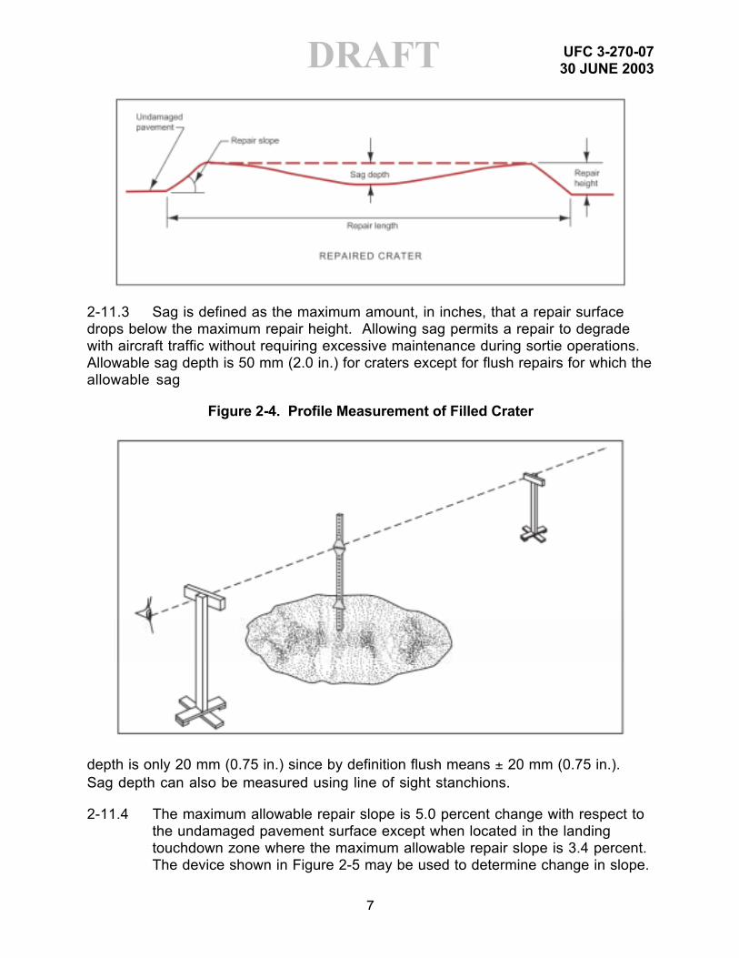
2-11.2 Pertinent RQC features of a repaired crater are shown in Figure 2-3. Criticalvalues are: repair height, sag depth, and repair slope. The allowable repair height isdetermined from a specific RQC chart for a specific aircraft under specific operatingand weather conditions. The actual crater repair height, measured as the differencebetween the height of the crater repair surface and the undamaged pavement surface,cannot exceed the maximum allowable value. The allowable crater repair height isgenerally a single number 25 to 152 mm (1 to 6 in.); however, an “F” or “FF” may bedesignated which indicates that the crater (or two successive craters, if FF isdesignated) must be a flush repair. The “F” indicates the requirement for a flushrepair for a single crater, and an “FF” designation indicates the requirement for a flushrepair for each of two successive craters. A flush repair cannot exceed ±20 mm(±0.75 in.) from the original undamaged pavement surface. All spall repairs areconsidered to be flush repairs. An expedient method of determining the height of acrater repair above the undamaged pavement is the use of stanchions and anelevation target as shown in Figure 2-4. The crater height is the difference betweenthe elevation rod readings at the top of the repair and on the undamaged pavement.Detailed guidance for the assembly and use of stanchions for establishing the extentof pavement upheaval around the crater and repair quality are provided in Appendix A.
Figure 2-3. Repaired Crater
UFC 3-270-0730 JUNE 2003
7
DRAFT
2-11.3 Sag is defined as the maximum amount, in inches, that a repair surfacedrops below the maximum repair height. Allowing sag permits a repair to degradewith aircraft traffic without requiring excessive maintenance during sortie operations.Allowable sag depth is 50 mm (2.0 in.) for craters except for flush repairs for which theallowable sag
Figure 2-4. Profile Measurement of Filled Crater
depth is only 20 mm (0.75 in.) since by definition flush means ± 20 mm (0.75 in.).Sag depth can also be measured using line of sight stanchions.
2-11.4 The maximum allowable repair slope is 5.0 percent change with respect tothe undamaged pavement surface except when located in the landingtouchdown zone where the maximum allowable repair slope is 3.4 percent.The device shown in Figure 2-5 may be used to determine change in slope.

UFC 3-270-0730 JUNE 2003
8
DRAFT2-12 REPAIR EVALUTION METHODS.
2-12.1 Acceptance Criteria. Crater repairs must be evaluated before acceptancefor aircraft operations. The following areas should be considered:
2-12.1.1 Repair Compaction. The strength of the backfill, debris, or subgradematerials must be verified. Depending upon the repair method used, the thicknessand strengths of all surface and/or base course materials must also be verified. Thesoil structure should be tested using a dynamic cone penetrometer (DCP) todetermine CBRs of each layer. These tests must be accomplished before placing theFOD covers, AM-2 matting, stone and grout, asphalt, concrete, or other surfacematerials that would prevent the use of the DCP. DCP measurements conductedaccording to procedures described in Appendix J of Reference 8b and Reference 12.
Figure 2-5. Five Percent Change of Slope (To convert feet tometers, multiply by 0.3048. To convert inches to
centimeters, multiply by 2.54)
2-12.1.2 Surface Roughness. The final grade of the repair must be checked usingline-of-sight profile measurement stanchions, upheaval posts, or string lines toensure the repair meets surface roughness criteria contained in Reference 3.Procedures are described in T.O. 35E2-5-1, Crushed-Stone Crater Repair and Line-Of-Sight Profile Measurement for Rapid Runway Repair. In the case of a crushedstone repair without a FOD cover, the repair surface should be checked for looseaggregate or FOD objects.
2-12.1.3 FOD Covers
2-12.1.3.1 FOD covers should be no more than 5 degrees off parallel with therunway centerline.
2-12.1.3.2 Check connection bolts and verify that all connections between panelsare tight and secure.
UFC 3-270-0730 JUNE 2003
9
DRAFT2-12.1.3.3 Check anchor bolts and verify that all bolts are secure and that the FODcover is held snugly against the pavement surface. In taxiway and apron applications,the leading and trailing edges of the FOD cover must be anchored. The side edgesmust also be anchored if the cover is located in an area where aircraft will be requiredto turn.
2-12.1.4 Setting/Curing. If the repairs are capped with concrete, stone and grout, orrapid-set materials, verify that the surface material has set and that adequate curetime is allowed prior to aircraft operations. Verification that the material has set canbe accomplished by probing the repair with a heavy object to ensure solidification ofthe repair material. Recommended curing times should be strictly followed to ensureadequate strength improvement prior to applying aircraft traffic.
2-12.1.5 Clean-up. For all repair methods, verify that the repair and adjacent area iscleared of any excess repair materials.
2-12.2 Airfield Certification
2-12.2.1 The on-site engineer responsible for the repair will certify that the repair wasaccomplished in accordance with the procedures in this ETL.
2-12.2.2 The repair procedures will be documented on an ADR log similar to the oneprovided in Appendix D. This form will then be updated to reflect subsequent aircrafttraffic and required maintenance throughout the history of the repair. If another teamreplaces the initial repair team, this form should be given to the follow-on team. Thisinformation will be useful in planning or performing any further maintenance and/orupgrade of the repairs.
2-12.2.3 Upon completion of repairs, the status of the airfield/repairs should beprovided to the airfield manager or other individual authorized to monitor and controlon-site aircraft operations. This individual can then issue a NOTAM to change theairfield status. If questions arise, the following contacts may be useful:
2-12.2.3.1 Navy/Marine Corps Operations. Contact the Marine Corps AirfieldService Officer. All AM-2 mat airfield installations on which aircraft operate under theirown power require certification in accordance with NAWCADLKE-MISC-48J200-0011.AM-2 mat expanses on which aircraft are towed only do not require certification. Theinspector must use the instructions and procedures in NAWCADLKE-MISC-48J200-0011 to ensure the structural and functional integrity of AM-2 mat and accessories.Annual certifications will be accomplished after the initial certification.
2-12.2.3.2 Air Force Operations
For questions regarding the suitability of paved airfields, contact Headquarters AirMobility Command, Airfield Analysis (HQ AMC/DOVS), DSN 779-3112.

UFC 3-270-0730 JUNE 2003
10
DRAFTFor questions regarding the suitability of semi-prepared airfields, contactHeadquarters Air Mobility Command, Directorate of Operations (HQ AMC/DOK), DSN779-3727.
If information on a particular airfield is not available from HQ AMC/DOVS or HQAMC/DOK, or if a site survey is required, contact Headquarters Air Mobility Command,Tanker Airlift Control Center, Mission Support Cell (HQ AMC TACC/XOPM), DSN 779-4015, who tasks Tanker Airlift Control Elements (TALCE) and/or Air MobilityOperations Groups (AMOG) to perform suitability surveys of paved airfields; orHeadquarters Air Force Special Operations Command, Operations and Training (HQAFSOC/DOO), DSN 579-4073, who tasks Special Tactics Teams (STT) through the720th Special Tactics Group, Operations and Training (STG/DOO), DSN 579-4250, toperform semi-prepared airfield or landing zone surveys.
UFC 3-270-0730 JUNE 2003
11
DRAFTCHAPTER 3
SPALL REPAIR
3-1 DEFINITION OF SPALL. A spall is damage that does not penetrate throughthe pavement surface to the underlying layers. Spalls may be up to 1.6 m (5 ft) indiameter. See Figure 2-1.
3-2 REPAIR CONCEPT. Repair of a spall requires few procedures: squaring ofthe edges, cleaning out and removing debris, apply bonding agent if required, placingthe fill material, finish the surface to provide a smooth structural bearing surface foraircraft traffic.
3-2.1 Purpose. This section provides guidance on repair of spalls. Althoughspalls are relatively small, they can be numerous. Thus, planning for spall repairshould receive close attention.
3-2.2 Concerns.
3-2.2.1 Manufacturer’s instructions. Insure that the manufacturer’s instructions,or rules of common practice, are strictly followed.
3-2.2.2 Bonding. The spall area must be prepared thoroughly. Sides should bevertical, loose material removed, and the repair surface clean or coated with abonding agent if applicable. Bad bonding will result in the patch coming loose.
3-2.2.3 Compaction of cold mix products. Failure to achieve density can result inrutting of the patch.
3-2.2.4 Joints. For all spall repairs, an attempt should be made to maintaincontinuity of existing pavement joints through the repair by using a spacer, such as apiece of backer rod or plywood, that is the width of the existing joint to maintain thejoint across the repair.
3-2.2.5 Safety. Follow all safety precautions. Some of the rapid setting materialsare toxic and flammable. Wear protective clothing. Dispose of excess materialproperly.
3-2.2.6 Debris. Sweep all areas to be trafficked by aircraft even if debris appearsminimal.
3-3 MATERIALS
3-3.1 Conventional Cement/Grout. A conventional cement grout mixture similar tothat indicated for Stone and Grout crater repair may be used in spall repair with peagravel substituted for 76-mm (3-in.) stone as the aggregate. A rapid setting cement(proprietary) must be used to obtain a compressive strength of 10.3 MPa (1500 psi) in4 hr. Consult the technical representatives for information on rapid setting cements.

UFC 3-270-0730 JUNE 2003
12
DRAFT3-3.2 Cold Mix Products. Tests conducted on a variety of cold mix patchingproducts have met with limited success. Conventional cold mix asphalt is suitable forsmall repairs up to 0.61 m (2 ft) in diameter and 1.83 mm (6 in.) deep. Proprietarypatching products can be used for both small and large spall repair; however, bothtypes of materials tend to rut easily.
3-3.3 Proprietary Products. Numerous commercial-off-the-shelf (COTS)materials are available. Some of these materials, particularly some rapid settingcements, have been tested and approved for DoD use while others have not. Beforeany material can be used on DoD airfields, it must be certified for use. Contact yourservice technical representative for the appropriate material and installationprocedures for your particular application.
3-3.4 Technical Representatives
3-3.4.1 Army. U.S. Army Engineer Research and Development Center,Geotechnical and Structures Laboratory, Airfields and Pavements Branch, Internethttp://pavement.wes.army.mil/, DSN 446-2731, commercial (601) 634-2731.
3-3.4.2 Navy. Naval Facilities Engineering Service Center, Code ESC63, Internethttp://www.nfesc.navy.mil/, DSN 551-1447, commercial (805) 982-1447, FAX (805)982-1074.
3-3.4.3 Marine Corps. Expeditionary Airfields (EAF) Aircraft Rescue and Firefighting(ARFF), HQMC ASL-38, DSN 224-1835, commercial (703) 614-1835/1028/2742, FAX(703) 697-7473.
3-3.4.4 Air Force. Headquarters Air Force Civil Engineer Support Agency, TechnicalSupport Directorate (HQ AFCESA/CES), Internet http://www.afcesa.af.mil, DSN 523-6334, commercial (850) 283-6334.
3-4 SPALL REPAIR/ACCEPTANCE PROCEDURES
3-4.1 Locate and mark spall areas. The remaining pavement around the spallshould be sounded to identify delaminated pavement layers adjacent to the existingspall. Sounding can be accomplished by using a heavy object to strike the pavementsurface and identifying changes in the acoustic response.
3-4.2 Square the edges of the spall as vertically as possible and remove loosedebris and pavement pieces.
3-4.3 If the surface of the spall is smooth, it may be desirable to groove thebottom crater surface to increase interface friction between the patch and cratersurfaces and to reduce the likelihood of the repair slipping out under aircraft traffic.
3-4.4 Prepare the surface of the spall as appropriate for the repair method. Forproprietary materials follow the manufacturer’s instructions. For cold mix asphaltrepairs, the surface should be primed with liquid asphalt if possible.

UFC 3-270-0730 JUNE 2003
13
DRAFT3-4.5 Prepare proprietary repair materials per the manufacturer’s instructions.Cement grout should be mixed following conventional procedures for grout andconcrete. Cold mix asphalt needs no preparation.
3-4.6 Place the repair material in the spall area. For grouts, simply screed off thesurface even with the surrounding pavement. For cold mix materials place thematerial in 50-mm- (2-in.-) thick layers compacting each layer with a plate compactor.Overfill the repair 38 mm (1.5 in.) and finish compacting with a vibratory roller. Onsmall repairs a plate compactor can be used. The finished surface should be flushwith these existing pavements.
3-5 SPALL REPAIR ACCEPTANCE CRITERIA. RQC specify that spall repairsshould be flush with the surrounding undamaged pavement with a tolerance of± 20 mm (0.75 in.).

UFC 3-270-0730 JUNE 2003
14
DRAFTCHAPTER 4
EXPEDIENT REPAIR METHODS
4-1 EXPEDIENT REPAIR CONCEPT
4-1.1 Purpose. Expedient repairs represent the minimum effort required torestore the MOS to a specified operational condition as described in para. 2-7.Desired time to complete expedient repairs is 4 hr after recovery efforts are initiated.However, the actual time to repair individual craters depends upon the availability ofpersonnel, equipment, and proper materials.
4-1.2 Assumptions. Equipment and manpower requirements for the variousservices are shown in Appendix A. Although these requirements are not presented interms of repair category, policy has been that the Air Force will conduct expedientrepairs and the Army will be largely involved in semi-permanent repairs. However,repair effort beyond expedient may involve assets of both services depending onmission requirements. Navy/Marine Corps guidance is that Naval MobileConstruction Battalions have the primary responsibility for airfield repair based onmission requirements. It is assumed that the appropriate assets will be available forany scenario. Time to repair could be affected by the presence of unfriendly elements.
4-2 SELECTION OF REPAIR METHOD
4-2.1 Aircraft Type and Load. Each aircraft has distinct characteristics (e.g., wingspan, tire pressure, load capacity, braking mechanism) that must be known whenchoosing the type of repair to accomplish.
4-2.2 Available Material. The type and quantity of material (e.g., backfill, crushedstone, fiberglass mat, spall, repair material, soil stabilization agents) available for arepair.
4-2.3 Available Equipment. The type and quantity of various pieces ofconstruction equipment (e.g., dozer, front-end loader, roller, concrete mixingequipment) available for a repair.
4-2.4 Repair Quality Criteria (RQC). A single number representing the maximumallowable repair height in inches that various aircraft can tolerate on an MAOS. SeeReference 3. See para. 2-11.
4-2.5 Existing Pavement Structure. The configuration of the current pavementlayers (e.g., concrete, asphalt over concrete, asphalt, compacted earth, etc.).
4-2.6 Time Constraints. The time allotted to accomplish the repairs before thefirst aircraft arrival or departure.

UFC 3-270-0730 JUNE 2003
15
DRAFT4-2.7 Repair Crew Capability/Equipment/Manpower. The repair crew’s capacityfor the task (e.g., experience, number of repair people, resource availability).Guidance on Equipment and Manpower Requirements is provided in Appendix B.
4-3 CRUSHED STONE REPAIR
4-3.1 Materials. Three types of repair methods are presented. Each involves theuse of a combination of crushed stone, ballast rock, or debris. Gradationspecifications for the ballast rock and crushed stone are shown in Tables 4-1 and4-2, respectively. Procedures for testing the gradation of materials are detailed inReference 13. If the repair materials fail to meet the gradation requirements in Tables4-1 and 4-2, the repair team should consider using an unsurfaced repair (Section 4-8.1), chemically stabilizing the materials (Section 4-8.2 and Ref. 11), or mechanicallystabilizing the material with sand grid (Section 4-4).
Table 4-1. Specifications for Ballast Rock
U.S. Standard Sieve SizeAllowable Range
(Weight % Passing)
3 in. 1002-1/2 in. 90 – 1002 in. 35 – 1001-1/2 in. 0 – 701 in. 0 – 153/4 in. 0 – 101/2 in. 0 – 5
Table 4-2. Specifications for High Quality,Well-Graded Crushed Stone
Crushed StoneSieve Designation No. 1 No. 2 No. 3
76 mm (3 in.) -- -- --64 mm (2.5 in.) -- -- --50 mm (2 in.) 100 -- --37.5 mm (1.5 in.) 70-100 100 --25 mm (1 in.) 45-80 60-100 10019.1 mm (3/4 in.) -- -- --12.5 mm (1/2 in.) 30-60 30-65 40-704.75 mm (No. 4) 20-50 20-50 20-502.0 mm (No. 10) 15-40 15-40 15-400.425 mm (No. 40) 5-25 5-25 5-250.075 mm (No. 200) 0-8 0-8 0-8

UFC 3-270-0730 JUNE 2003
16
DRAFT
4-3.2 Types of Repair Methods.
4-3.2.1 Debris Backfill. Use when subsurface debris is plentiful and suitable for filling thecrater. Fill the crater with debris up to 457 mm (18 in.) below the surface. Fill the remainingportion of the crater with crushed stone meeting the gradation requirements shown in Table 4-2.See Figure 4-1.
Figure 4-1. Debris Backfill
4-3.2.2 Choke Ballast Over Debris. Use when subsurface debris is suitable for fill,but limited. Fill the crater with useable debris up to a maximum of 609 mm (24 in.)below the pavement surface. Continue to fill the crater up to 457 mm (18 in.) belowthe surface with ballast rock meeting the requirements shown in Table 4-1, and fill theremaining portion of the crater with crushed stone meeting the requirements shownin Table 4-2. See Figure 4-2.
Figure 4-2. Choke Ballast over Debris

UFC 3-270-0730 JUNE 2003
17
DRAFT4-3.2.3 Choke Ballast Repair. Use when water is standing in the crater or ifsubsurface material is unsuitable for filling the crater. Fill the crater with ballast rockmeeting the requirements shown in Table 4-1 up to 457 mm (18 in.) below thepavement surface. Fill the remaining portion of the crater with crushed stone meetingthe requirements shown in Table 4-2. See Figure 4-3.
Figure 4-3. Choke Ballast
4-3.3 Procedures.
4-3.3.1 Clear debris from around the crater at least 9.1 m (30 ft) in all directions toallow identification of the upheaved pavement surface. Identification and removal ofall upheaval or damaged pavement is critical. It cannot be rolled down flush with theexisting pavement and left. The upheaved pavement will eventually break up andcreate additional problems adjacent to the crater repair.
4-3.3.2 Perform profile measurement and visual inspection to identify and markupheaval around the crater.
4-3.3.3 Remove upheaved pavement using an excavator with bucket or moil pointattachment, and a front-end loader. A dozer may also be used, depending on therunway surface.
4-3.3.4 All debris material in excess of 304 mm (12 in.) in diameter must beremoved or reduced in size. Breaking the pavement into smaller pieces will minimizethe potential for voids and settling problems in the future.
4-3.3.5 Push unusable debris at least 9 m (30 ft) off the MOS and pile no higherthan 0.9 m (3 ft).
4-3.3.6 Place backfill material (debris and/or ballast rock) into the crater inaccordance with the repair procedure chosen. Note: If settling problems areanticipated, placement of a geotextile fabric between dissimilar backfill materials isrecommended to prevent intermingling. The use of a medium weight geotextile is

UFC 3-270-0730 JUNE 2003
18
DRAFTrecommended for separation applications in pavements and the National StockNumber for the DOD recommended products is NSN: 5675-01-471-2647.Appropriate geotextile products are not included in some ADR kits. This backfillshould have a minimum strength of 4 CBR for a depth ranging from 18 to 30 inchesbelow the pavement surface. The maximum CBR reasonably attainable should beachieved for backfill below 30 in. from the surface. Generally this can be achieved bynormal traffic of the construction equipment used to fill, spread, and roll down thebackfill. For small craters (less than 20-ft diameter) where heavy equipment cannotoperate, the backfill material should be compacted to the greatest extent possible withthe assets available (hand tampers, pneumatic tampers, plate compactors, etc.). Ifthe crater backfill cannot be adequately compacted, the repair may provided initialoperational capability, but will require frequent maintenance. The CBR may bechecked using a Dynamic Cone Penetrometer following instructions given inReferences 8a and 8b.
4-3.3.7 Fill the crater with crushed stone material and compact, placing it in liftsapproximately 152 to 177 mm (6 to 7 in.) thick. For jet aircraft operations, limit theaggregate size to a maximum of 25 mm (1 in.) in the top 152 mm (6 in.) of the crushedstone repair. Overfill the crater by approximately 76 mm (3 in.) above the originalpavement surface height. Compact each lift of crushed stone using a minimum offour passes of a 5-ton single-drum vibratory roller or two passes of a 10-ton vibratoryroller. One pass of the roller means traveling across and back in the same lane. Ifthe crushed stone material is placed upon soft subgrade materials, it may bebeneficial to separate the material using a geotextile fabric and place the crushedstone material in thicker lifts. In any case, the crushed stone should be compactedwith a minimum of four passes of a single-drum vibratory roller or two passes of a10-ton vibratory roller per each 152 mm (6 in.) of thickness. A 457-mm (18-in.)crushed stone layer should receive a minimum of 12 passes with a single-drum5-ton vibratory roller or six passes with a 10-ton vibratory roller prior to cut for the finalgrade.
4-3.3.8 Grade the compacted crushed stone to approximately 25 mm (1 in.) abovethe pavement surface.
4-3.3.9 Compact the crushed stone using an additional two passes of a 5-tonsingle-drum vibratory roller or one pass with a 10-ton vibratory roller. The crushedstone layer should have a minimum 25 California Bearing Ratio (CBR) to supportC-17 operations or a minimum 15 CBR to support C-130 operations. CBR valuesmay be determined using a Dynamic Cone Penetrometer (DCP). For guidance onuse of the DCP, see References 8a and 8b.
4-3.3.10 Perform profile measurements. The repaired crater must not exceed themaximum RQC of ±19 mm (±0.75 in.). A repair outside this tolerance may still beuseable, depending on its location, but will have a much shorter life before requiringadditional maintenance to bring it back within this limitation and may result in aircraftdamage.

UFC 3-270-0730 JUNE 2003
19
DRAFT4-3.3.11 The crushed stone repair is complete at this point. Depending on theparticular location on the airfield or the type of mission aircraft, it may be left uncoveredor may require a FOD cover to reduce debris damage to aircraft. Guidance forassembly and placement of FOD covers is presented in para. 4-5.
4-4 SAND-GRID REPAIR. (See Figures 4-4 and 4-5.)
4-4.1 Clear debris from around the crater at least 6 m (20 ft) in all directions toallow identification of the upheaved pavement surface. Identification and removal ofall upheaval or damaged pavement is critical. It cannot be rolled down flush with theexisting pavement and left. The upheaved pavement will eventually break up andcreate additional problems adjacent to the crater repair.
4-4.2 Perform a profile measurement and visual inspection to identify and markthe upheaval around the crater.
Figure 4-4. Sand Grid Repair
Figure 4-5. Sand Grid Repair Detail

UFC 3-270-0730 JUNE 2003
20
DRAFT
4-4.3 Break out the upheaved pavement.
4-4.4 Square the sides of the crater to vertical from the original pavement surfacedown to 406 mm (16 in.).
4-4.5 All debris material in excess of 304 mm (12 in.) in diameter must beremoved or reduced in size.
4-4.6 Move unusable debris at least 9 m (30 ft) off the MOS and stockpile nohigher than 0.9 m (3 ft).
4-4.7 Standing water in the crater should be pumped or bailed out, if possible,using any means available.
4-4.8 Any reinforcing material protruding from the original pavement must be cutoff and removed.
4-4.9 Clean an area 30 m (100 ft) from the crater edge for assembling the FODcover, if possible. It is preferable that the mat assembly site be no further than 0.8 km(0.5 mile) from the repaired crater. An area approximately 15 m by 15 m (50 ft by 50 ft)square is required for assembling the mat.
4-4.10 Backfill the crater with useable debris or a combination of debris, crushedstone, or ballast rock (minimum 156 mm (6 in.)). Level this material to 406 mm(17 in.) below the original pavement surface. This measurement is critical to ensurea flush repair.
4-4.11 Compact the debris backfill to a minimum 4 CBR.
4-4.12 Line the backfilled crater with a geotextile to separate dissimilar materials.The use of a medium weight geotextile is recommended for separation applicationsin pavements and the National Stock Number for the DOD recommended products is

UFC 3-270-0730 JUNE 2003
21
DRAFTNSN: 5675-01-471-2647. Appropriate geotextile products are not included in someADR kits.
4-4.13 Place the first layer of sand-grid (NSN: 5680-01-198-7955) parallel to thecenterline of the runway. Place fill material or short U-shaped pickets in the corners ofthe grid and along the sides to hold it in place.
4-4.14 Backfill the sand-grid using cohesionless material, if possible. Overfill thegrid by approximately 50 mm (2 in.).
4-4.15 Compact this first layer of fill material. Typically, two passes with a vibratoryroller are required for compaction.
4-4.16 After compaction, all excess material must be struck off level with the top ofthe sand-grid. This is critical to ensure a flush repair meeting the RQC.
4-4.17 Place a geotextile over the first layer of sand-grid.
4-4.18 Lay the second layer of sand-grid perpendicular to the first layer and therunway centerline.
4-4.19 Backfill and overfill the sand-grid using cohesionless material, if possible.
4-4.20 Compact this layer of backfill. If the two sand-grids were installed andcompacted properly, the sand-grid should not protrude above the pavement surface.
4-4.21 Grade off excess material so the repair is flush with the original pavementsurface.
4-4.22 Install and anchor the FRP mat cover. The sand-grid repair must have aFOD cover installed to be operational. Guidance for assembly and placement of FODcovers is presented in para. 4-5.
4-4.23 Verify that the repair does not exceed surface roughness criteria.
4-5 FOREIGN OBJECT DAMAGE (FOD) COVERS. FOD covers are generallyrequired to prevent damage to aircraft engines. The Army, Navy/Marine Corps, and AirForce each have its version of a plastic type FOD cover. Descriptions of each type ofmat and guidance for assembly of the mat over craters are presented in this section.Although AM-2 matting can be used as a FOD cover, it is more appropriately used asa structural surfacing for crater repair.
4-5.1 Army FOD Cover Assembly Procedures
4-5.1.1 This FOD cover is referred to as a Fiberglass Reinforced Panel (FRP) mat.The Army ADR kit contains FRP panels in three sizes. All FRP panels are 13 mm(0.5 in.) thick. There are four full-size panels (5.49 m by 2.01 m [18 ft by 6.6 ft]); tworight-half panels (2.62 m by 2.01 m [8.6 ft by 6.6 ft]); and two left-half panels (2.83 m by

UFC 3-270-0730 JUNE 2003
22
DRAFT2.01 m [9.3 ft by 6.6 ft]). When assembled, this cover will cap one crater 7.6 m (25 ft)in diameter. See Table 4-3.
Table 4-3. Army FRP Panel Types
Type Size, m (ft)Number per
Kit
Full Size 5.49 × 2.01 (18 × 6.6)
4
Right Half 2.62 × 2.01 (8.6 × 6.6)
2
Left Half 2.83 × 2.01 (19.3 × 6.6)
2
4-5.1.2 Assembled mat dimensions are 8.11 m by 8.11 m (26.6 ft by 26.6 ft). Onone side and on one end of the mat are holes 63.5 mm (2.5 in.) in diameter forinserting anchor bushings or connector bushings.
4-5.1.3 Position the panels on a smooth level surface for assembly. Assemble in abrickwork-type pattern.
4-5.1.4 Install and tighten panel-connecting bolts as each row of panels is aligned.
4-5.1.5 Pull the assembled mat into position over the crater. The mat must overlapthe crater edges by at least 304 mm (12 in.) on each side.
4-5.1.6 Secure the mat on the leading and trailing edge or perpendicular to thedirection of flight. Drill pilot holes for the anchor bolts.
4-5.1.7 Anchoring the FRP mat over damaged concrete pavement uses a Wej-itanchor bolt. There are two sizes of Wej-it bolts in the kit: the bolt 177.8 mm long by15.9 mm in diameter (7 in. long by 0.625 in. in diameter) is installed using rotaryhammer tools; the bolt 177.8 mm long by 19.1 mm in diameter (7 in. long by 0.75 in.in diameter) is placed with the SEE (for this bolt, a pilot hole must be drilled 203 mm[8 in.] deep with a 19.1-mm [0.75-in.] bit).
4-5.1.8 Anchoring the FRP mat over damaged asphalt concrete pavement uses ascrew spike style F head. This screw is 152.4 mm long by 19.1 mm in diameter (6 in.long by 0.75 in. in diameter). A pilot hole must be drilled 177 mm deep by 15.9 mm indiameter (7 in. deep by 0.625 in. in diameter).

UFC 3-270-0730 JUNE 2003
23
DRAFT4-5.2 Navy-Marine Corps FOD (FRP)
4-5.2.1 Airfield Damage Repair (ADR) Kit Description
4-5.2.1.1 The Navy-Marine Corps ADR kit consists of an air-shippable InternationalOrganization for Standardization (ISO), Series 1C, 8- by 8- by 20-ft container; interiortrack/rail hardware; and the necessary tools, materials, and ancillary equipment toeffect the assembly, installation, and maintenance of four 10.8-m-wide by 9.92-m-long(34-2/3-ft-wide by 32-ft-long) (approximate dimensions) FRP FOD cover panels; orone 21.5-m-wide by 19.2-m-long (69-1/3-ft-wide by 62-ft-long) (approximate) FRP FODcover panel. The ADR kit has been designed to enable rapid response to a runwayrepair Foreign Object Damage (FOD) requirement.
4-5.2.1.2 Panel Description. All FRP panels are 9.5 mm (3/8-in.) thick. Five types ofpanels are provided, as shown in Table 4.4. Panels are assembled into mats bymeans of bolts fitted through bushings that are incorporated into the panels at thetime of manufacture (Figure 4-6). Tapered ramp panels are used at mat edges,perpendicular to the direction of air traffic, to facilitate the passage of aircraft tailhooks. Anchor bolts secure the mats to the pavement surface along the mat edges.
Table 4-4. Navy-Marine Corps FRP Panel Types
Type Size, m (in.)Number perContainer
Full-size 5.5 × 2 (216 × 80)
24
Left half-size 2.9 × 2 (112 × 80)
8
Right half-size 2.9 × 2 (112 × 80)
8
Ramp panel 5.3 × 0.9(208 × 36)
16
Center panel 5.5 × 1.0(216 × 40)
8
Figure 4-6. FRP Panel Bushing Detail (To convert inchesto millimeters, multiply by 25.4)

UFC 3-270-0730 JUNE 2003
24
DRAFT
4-5.2.1.3 FRP Mat Configuration. A typical FRP mat configuration (Figure 4-7)consists of the following panels required to cover a 7.6-m- (25-ft-) diam crater:
4 Ramp panels6 Basic panels2 Center panels2 Left half-size panels2 Right half-size panels
Figure 4-7. Typical Navy-Marine Corps FRP Mat Layout

UFC 3-270-0730 JUNE 2003
25
DRAFT
4-5.2.1.4 Typical Container Complement. Based on the foregoing, a typicalcomplement of panels in a container would be:
16 Ramp panels24 Basic panels 8 Center panels 8 Left half-size panels 8 Right half-size panels
When these panels are assembled into a mat, they will cover a 15-m- (50-ft-) diamcrater. Panel towing assembly is also included in this kit.
4-5.2.1.5 Mat Assembly Sites. Mat assembly sites should be within 400 m(0.25 mile) of the craters to be repaired, on a firm surface (not necessarily paved), solocated that the mats can be towed to crater sites without traversing obstructions orinterfering with other activities on the runway or taxiway. Mat assembly sites androutes from sites to craters must be clear of unexploded ordnance (UXO) and mayrequire decontamination of chemical warfare agents. A mat can be towed overuneven terrain free from sharp obstructions such as rocks or tree stumps.
4-5.2.1.6 Mat Assembly. A mat for a 15-m- (50-ft-) diam crater can be assembled bya crew of 14 in 1.5 hr, including removal from the container, layout, and assembly.Generally, there is time to assemble a mat while the crater is being backfilled.Therefore, begin mat assembly as soon as the approximate size of the repair area isknown. Alternatively, mats can be preassembled to a nominal size as in Figure 4-7and expanded should larger craters be encountered.
4-5.2.1.7 Assembly Procedure. Assemble mats as shown in Figure 4-8. Start in thecenter of mat and work outward so that two crews can work at one time. Brief the

UFC 3-270-0730 JUNE 2003
26
DRAFTpanel crew to ensure that all personnel understand the order of panel assembly.Adjust panels into position with a pry bar. Carry bolts, bushings, and tools inlineman’s tool bags. The finished mat will have a pattern similar to that in Figure 4-7depending on the mat size. The following is a recommended sequence forassembling a FOD cover.
(1) Estimate the dimensions of the required crater FOD cover. This can be doneas soon as the crater to be repaired is identified. After removal of upheaved material,the desired cover dimensions can be defined more accurately. Note: Provide aminimum overlap of 0.6 m (24 in.) over the crater breakout boundary. (Refer toFigures 4-8 and 4-9 during the assembly procedure.)
(2) Begin mat assembly from the center of the mat, working in both directionstoward the ends (ramp panels) that will be aligned with Minimum Operating Strip(MOS) when the mat is installed. (The MOS is the smallest area that must berepaired in order to launch and recover aircraft after an attack.)
(3) Align bolts and bushings carefully. A screwdriver is useful for alignment.Tapping a 50-mm by 102-mm (2-in. by 4-in.) block of wood along a panel edge isanother technique for alignment of the bolts and bushings.
(4) Tighten bolts with socket wrenches starting from a panel center, workingtoward panel edges.
Figure 4-8. Mat Assembly Sequence

UFC 3-270-0730 JUNE 2003
27
DRAFT4-5.2.1.8 Crater Area Cleanup. Crater area cleanup consists of the following steps:
(1) Sweep area around backfilled crater carefully with a rotary sweeper.
(2) Sweep pavement route over which mat is to be towed to extent that willpreclude dragging debris onto the backfilled crater surface.
4.5.2.1.9 Mat Towing. A large assembled mat can be towed by a 2721 kg- (6,000-lb-)capacity, rough-terrain forklift; a 5-ton 6 by 6 cargo truck; or a vehicle with equivalenttowing capability. Towing is accomplished by use of the FRP Cover Towing System.Two towing configurations are illustrated: (1) for towing a small mat, approximately16.7-m by 10-m (34-2/3-ft by 32-ft) long (Figure 4-10) and (2) for towing a large mat21.5-m by 19.2-m (69-1/3-ft by 62-ft) long (or similar size) (Figure 4-11). For eithersize mat position the mat so that the center of mat is lined up with centerline of craterto be covered. Pull straight ahead over the crater centerline. Ensure that mapoverlaps the crater by several feet on all sides.
Figure 4-9. Mat Assembly

UFC 3-270-0730 JUNE 2003
28
DRAFT
Figure 4-10. Small FRP Cover Towing System

UFC 3-270-0730 JUNE 2003
29
DRAFT
Figure 4-11. Large FRP Cover Towing System

UFC 3-270-0730 JUNE 2003
30
DRAFT4-5.2.1.10 Mat Anchorage – Portland Cement Concrete Pavement. The mat isfastened to the concrete pavement with 0.625- by 5-in. WEJ-IT bolts through thebushings in the mat edges into holes drilled in the pavement. To anchor the mat,perform the following steps:
(1) Mark drill bit with tape to ensure drilling to a depth of 203 mm (8 in.).
(2) Drill holes for WEJ-IT bolts using a bushing as a template. Drill holes203 mm (8 in.) deep to ensure that the bolt can be driven into place if cuttings remainin hole.
(3) Clear dust from hole with a compressed airjet or airbulb.
(4) Insert WEJ-IT bolt through the top bushing, ensuring that the wedges andwasher are properly set, and stamp it into place to start.
(5) Drive the bolt into place carefully with a sledge hammer. Too hard of aninitial blow may force the bolt’s wedges prematurely.
(6) Torque bolts to 81.36 joules (60 ft-lb).
(7) If a bolt protrudes above bushing, grind off bolt head until it is flush withbushing.
(8) Complete installation by sweeping mat and adjacent pavement.
4-5.2.1.11 Mat Anchorage – Asphalt Concrete Pavement. An enlarged bushing isprovided (Reference 7) for fastening the mat to AC or earth. Alternatively, a WEJ-IT boltmay be used in a larger hole and grouted in.
(1) Large Bushing Method. Use the following procedures for the large bushingmethod:
(a) Remove regular bushing from prefabricated panel with a hammer andchisel, being careful so as not to damage panel.
(b) Provide a countersink for the large bushing by drilling a 63.5-mm-(2.5-in.-) diam hole in AC pavement concentric with the center of hole in the mat, to adepth of 47.6 mm (1.875 in.). Use tape on drill bit to determine the drilled depth.
(c) Insert large bushing and drill a 38.1-mm (1.5-in.) hole into AC pavementthrough hole in bottom of bushing.
(d) Remove bushing.
(e) Insert earth anchor and seat it so that it will not project above matsurface.
(f) Replace bushing over earth anchor, and fasten bushing to earth anchor.

UFC 3-270-0730 JUNE 2003
31
DRAFT(2) WEJ-IT Bolt Method. Use the following steps for the WEJ-IT bolt method:
(a) Remove bushing from mat as described in para. 4-5.2.1.11(1)(a).
(b) Through bushing hole in mat, drill a 38.1-mm (1.5-in.) hole in AC to adepth of 127 mm (5 in.), using bushing as a template.
(c) Remove wedges from WEJ-IT bolt.
(d) Mix and pour polyurethane or other rapid setting polymer material intohole in AC to a level such that when WEJ-IT bolt is inserted, grout level will be justbelow underside of bushing.
(e) Insert WEJ-IT bolt into bushing so that top of nut is flush with bushing.
(f) Insert bolt into grout material and step on it until polymer has set(approximately 1 min).
(g) Tighten bushing down with WEJ-IT bolt nut and wrench.
4-5.3 Air Force Folded Fiberglass Mat (FFM).
4-5.3.1 The FFM is air-transportable, can be moved easily by vehicles, can bepositioned at greater distances from airfield pavement surfaces, and can be storedindoors out of the elements.
4-5.3.2 A standard FFM weighs about 1360 kg (3,000 lb) and consists of ninefiberglass panels, each 1.83 m wide by 9.14 m long by 12.7 mm thick (6 ft wide by30 ft long by 0.5 in. thick). Elastomer hinges 76.2 mm (3 in.) wide connect the panels.When folded, these mats are 1.83 m wide by 9.14 m long and 203 to 254 mm thick(6 ft wide by 30 ft long and 8 to 10 in. thick). (See Figure 4-12)
4-5.3.3 This repair system also includes joining panels and two support mat kits.The joining panels come in 7.32-m and 9.14-m (24-ft and 30-ft) lengths. One of eachsize is needed to connect two 9.14-m by 16.46-m (30-ft by 54-ft) mats. The resulting16.46-m by 18.29-m (54-ft by 60-ft) mat is the normal size suitable for most craterrepairs. If larger FOD covers are required, additional mats may be spliced together.
4-5.3.4 There are two types of support mat kits for the FFM. Mat Kit A contains allthe necessary tools and hardware required to assemble, install, and maintain thesystem. Mat Kit B contains the anchor bolts required to attach the mat to thepavement surface.
4-5.3.5 The mat assembly area can be any area near the crater repair. This areamust be cleared of all debris and swept. It must be large enough to accommodatethe unfolding of both mats, allow equipment operations around the mat, and notinterfere with crater preparations. This area should be approximately 30.4 m by30.4 m (100 ft by 100 ft) square, and located a minimum of 30.4 m (100 ft) from thecrater and off the MAOS.

UFC 3-270-0730 JUNE 2003
32
DRAFTFigure 4-12. FFM Configuration
4-5.3.6 Mats are placed end-to-end about 1.2 m (4 ft) apart, with the first panel upand positioned such that both mats unfold in the same direction.
4-5.3.7 Unfold the mats in preparation for being joined together. The top panel ofthe mat is attached to a tow vehicle with a nylon strap (Figure 4-13). A crew of fourpeople, or a forklift positioned on the opposite side of the mat, lifting each successivepanel as the mat is being pulled open, speeds the unfolding process (Figure 4-14).
4-5.3.8 Resin flaking at the mat hinge can occur and create a FOD problem withmats that were procured from the initial manufacturing programs. To eliminate thisproblem, make one pass with a vibratory roller down each hinge, followed with asweeper. This operation normally loosens and removes the flaking material from thehinges.
4-5.3.9 Join the mats together so they are aligned, the 9.14-m (30-ft) edges areeven, and the 16.46-m (54-ft) edges are roughly parallel with each other.

UFC 3-270-0730 JUNE 2003
33
DRAFTFigure 4-13. Attaching Nylon Straps
Figure 4-14. Mat Unfolding Procedure

UFC 3-270-0730 JUNE 2003
34
DRAFT4-5.3.10 Lift one end of the 16.46-m (54-ft) edge and slip either the 7.32-m (24-ft) orthe 9.14-m (30-ft) section of joining panel underneath the raised edge. Align theholes in the mat with the joining panel bushing holes and lower the mat (Figure 4-15).
Figure 4-15. Joining Panel Attachment
4-5.3.11 Install the top joining bushings and tighten by hand. This process isrepeated at the other end of the 16.46-m (54-ft) edge of the same mat using theremaining joining panel. Hand-tighten these bushings; final tightening will beaccomplished later.
4-5.3.12 The second mat is then towed over to the first mat with joining panel attached. Oneof the holes near the end of the second mat is aligned with its counterpart on the joining panel anda top joining bushing is installed (Figure 4-16).

UFC 3-270-0730 JUNE 2003
35
DRAFTFigure 4-16. Joining Second Mat Using Pivot Point
4-5.3.13 This end connection acts as a pivot point when the second mat is movedinto
position so all the remaining holes on the joining panel are in alignment. Install theremaining top bushing and tighten the entire second mat bushing with an impactwrench.
4-5.3.14 Revert to the first top joining bushings and tighten them with the impactwrench. All joining bushings should be tightened and the joined mats are now readyto be towed over the repaired crater.
4-5.3.15 Before any towing operation can commence, the area between the matassembly area and the repaired crater must be completely swept. Any debris that ispicked up under the mat as it is being towed could damage the matting and affect thesmoothness of the repair.
4-5.3.16 When the width of the MAOS permits, the mat should be towed parallel toand next to the crater. Align the joining panel with the center of the crater. Use a front-end loader or similar vehicle to tow the mat over the crater with the hingesperpendicular to the tow direction. Position the mat so the hinges are parallel to thedirection of the MAOS traffic. The mat should not be more than 5 degrees off parallel.
4-5.3.17 With the mat in position over the crater, it must be anchored in place.Techniques for anchoring the FFM will depend on the type of pavement surface. TheFFMs are predrilled for anchoring bolts. All three anchoring techniques use a101.6-mm (4-in.) bushing through which the bolt passes to hold down the mat.
4-5.3.17.1 Concrete Pavements (Figure 4-17). The concrete anchor is normally arock bolt that is 127 to 152.4 mm long and 15.9 to 19.1 mm in diameter (5 to 6 in. long

UFC 3-270-0730 JUNE 2003
36
DRAFTand 0.625 to 0.75 in. in diameter). At each predrilled hole in the leading and trailingedges of the mat, drill a hole into the pavement corresponding to the diameter of thebolt being used. Position an anchor bushing in the predrilled hole as a guide forcentering the drill bit. The depth of the hole must be at least 12 mm (0.5 in.) longerthan the length of the bolt. Clean out the drill cutting with compressed air and insertthe bolt through the bushing. Stand on the mat and bushings and tighten the bolt withan impact wrench.
4-5.3.17.2 Asphalt-overlaid Concrete Pavements. Asphalt-overlaid concreteusually entails using a rock bolt that is 241.3 mm long and 15.9 to 19.1 mm indiameter (9.5 in. long and 0.625 to 0.75 in. in diameter). The installation procedure isthe same as those for all-concrete pavements. The key factor in this installation is toensure the bolt has been set deep enough into the concrete layer for a firm grip.
4-5.3.17.3 Asphalt Pavements (Figure 4-18). Anchoring in asphalt pavementrequires a 241.3-mm (9.5-in.) bolt and polymer. A hole 254 mm deep and 38 mm indiameter (10 in. deep and 1.5 in. in diameter) is drilled at the center of each predrilled
mat hole. A two-part resin polymer is mixed and poured into each hole to about38 mm (0.5 in.) below the surface of the pavement. An anchor bushing and bolt areimmediately placed into each hole and pressed firmly (standing on the bolt andbushing) against the mat. The polymer will harden in about three minutes. Drillingand setting the bolts are usually accomplished concurrently to expedite the repairprocess.
Figure 4-17. Concrete Pavement Anchoring

UFC 3-270-0730 JUNE 2003
37
DRAFT
Figure 4-18. Asphalt-Overlaid Concrete Anchoring
4-6 AM-2 MAT REPAIR. The AM-2 mat repair method consists of placing apatch of AM-2 over the filled and compacted crater. The crater should be backfilledwith debris and 406 mm (18 in.) of crushed stone following procedures for thecrushed stone debris backfill repair indicated in para 4-3 and Figure 4-1. Restrictionson use of AM-2 are noted in Table 2-1. The Air Force also notes that the AM-2 patchtechnique has been in existence for almost 30 years (1997). Once the mainstay ofADR operations, it has been primarily relegated to secondary use. AM-2 mat repairsare generally acceptable for fighter aircraft when spacing between the patches is
UFC 3-270-0730 JUNE 2003
38
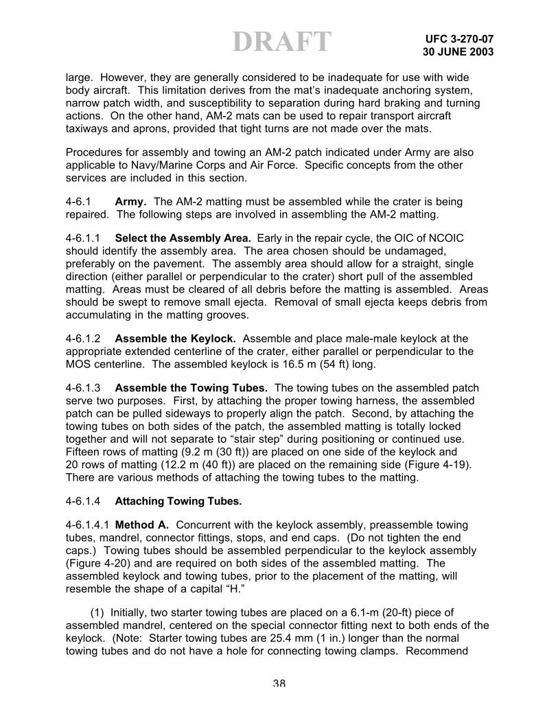
DRAFTlarge. However, they are generally considered to be inadequate for use with widebody aircraft. This limitation derives from the mat’s inadequate anchoring system,narrow patch width, and susceptibility to separation during hard braking and turningactions. On the other hand, AM-2 mats can be used to repair transport aircrafttaxiways and aprons, provided that tight turns are not made over the mats.
Procedures for assembly and towing an AM-2 patch indicated under Army are alsoapplicable to Navy/Marine Corps and Air Force. Specific concepts from the otherservices are included in this section.
4-6.1 Army. The AM-2 matting must be assembled while the crater is beingrepaired. The following steps are involved in assembling the AM-2 matting.
4-6.1.1 Select the Assembly Area. Early in the repair cycle, the OIC of NCOICshould identify the assembly area. The area chosen should be undamaged,preferably on the pavement. The assembly area should allow for a straight, singledirection (either parallel or perpendicular to the crater) short pull of the assembledmatting. Areas must be cleared of all debris before the matting is assembled. Areasshould be swept to remove small ejecta. Removal of small ejecta keeps debris fromaccumulating in the matting grooves.
4-6.1.2 Assemble the Keylock. Assemble and place male-male keylock at theappropriate extended centerline of the crater, either parallel or perpendicular to theMOS centerline. The assembled keylock is 16.5 m (54 ft) long.
4-6.1.3 Assemble the Towing Tubes. The towing tubes on the assembled patchserve two purposes. First, by attaching the proper towing harness, the assembledpatch can be pulled sideways to properly align the patch. Second, by attaching thetowing tubes on both sides of the patch, the assembled matting is totally lockedtogether and will not separate to “stair step” during positioning or continued use.Fifteen rows of matting (9.2 m (30 ft)) are placed on one side of the keylock and20 rows of matting (12.2 m (40 ft)) are placed on the remaining side (Figure 4-19).There are various methods of attaching the towing tubes to the matting.
4-6.1.4 Attaching Towing Tubes.
4-6.1.4.1 Method A. Concurrent with the keylock assembly, preassemble towingtubes, mandrel, connector fittings, stops, and end caps. (Do not tighten the endcaps.) Towing tubes should be assembled perpendicular to the keylock assembly(Figure 4-20) and are required on both sides of the assembled matting. Theassembled keylock and towing tubes, prior to the placement of the matting, willresemble the shape of a capital “H.”
(1) Initially, two starter towing tubes are placed on a 6.1-m (20-ft) piece ofassembled mandrel, centered on the special connector fitting next to both ends of thekeylock. (Note: Starter towing tubes are 25.4 mm (1 in.) longer than the normaltowing tubes and do not have a hole for connecting towing clamps. Recommend

UFC 3-270-0730 JUNE 2003
39
DRAFTthese tubes, four each per patch kit, be identified and painted a distinctive color toreadily differentiate from normal towing tubes.)
Figure 4-19. Attachment of Towing Tubes
(2) The starter tube that receives the first piece of matting placed on the keylockmust be placed on the mandrel with the prongs facing up. The starter tube thatreceives the last piece of matting from the first row must be placed on the mandrelwith prongs up also, but will be rotated to prongs down when attached to the matting(Figure 4-20).
Figure 4-20. Towing Tube and Keylock

UFC 3-270-0730 JUNE 2003
40
DRAFT
(3) Place sufficient towing tubes (15 on one side and 20 on the other) andmandrels with connector fittings to accommodate total patch. If there are fewer thanfive mats remaining at the end of the patch, use a short mandrel for each one. Towingtubes should be placed with prongs located identical to the starter tubes.
(4) After all tubes are placed on the mandrels (total of 2 starter tubes and33 towing tubes on each side), place the stop and end cap on each end of themandrel. (Do not tighten end caps until total matting patch has been assembled.)
4-6.1.4.2 Method B. As the first mat is placed starting a new row, connect the towingtubes to the left (looking toward the keylock) side of the matting. After each row ofmats has been completed, connect the towing tube to the right side of the matting.Insert the locking bar between the mats and the tube as each connection is made.

UFC 3-270-0730 JUNE 2003
41
DRAFTPlace a starter tube on each side of the keylock, on each side of the patch (four startertubes required). After all tubes are placed (15 on one side and 20 on the other), inserta long mandrel with tapered bullet nose attached in the tube, from the end of the patch(Figure 4-21).
Figure 4-21. Towing Mandrel and Mandrel Fittings
(1) Using the connector fitting, connect another long mandrel to the first mandrel.Be sure that the connector is threaded all the way into the mandrel and no threads areshowing. Push this assembly into the towing tube and connect another long mandrel.Repeat this procedure until the bullet nose emerges at the opposite end of the towingtube. It will be necessary to install one extra mandrel so as to provide adequatespacing to remove the bullet nose and install towing bar stop and cap.
(2) After the towing bar stop and cap have been installed on one end, pull themandrel so that the stop is flush against towing tube. Then remove the additionalmandrel from opposite end and insert a towing bar stop and cap at that end. Makesure that the long end of these stops is facing in toward the patch and they clear themat ends.

UFC 3-270-0730 JUNE 2003
42
DRAFT(3) Tighten the ends equally, using the crescent wrench provided in the tool
chest. If the panels expand so that the patch is longer than the assembled towingtube, add more stops (as a shim) from the spare stops provided in the kit. Tighten thecaps at each end of the tube as tight as possible. Make sure that tubes are seatedcorrectly.
4-6.1.4.3 Method C. Attaching Towing Tubes (Preferred Method). This is a build-as-you-go method that is done concurrently with the mat assembly.
(1) Use one long connector to connect two long mandrels on each side of theend of the keylock.
(2) After mandrels are connected and laid out, slide two starter tubes, centeringthem on each mandrel at the center connector fitting. Remember, starter tubes are25.4 mm (1 in.) longer than the towing tube and do not have holes drilled for thetowing harness.
(3) Since the matting is always laid from left to right facing the mat layingoperation, the starter tube that receives the first piece of matting placed on the keylockmust be placed on the mandrel with the prongs facing up. The starter tube thatreceives the last piece of matting from the first row must be placed on the mandrelwith the prongs up and (when connected to the end of the matting) must be rotated180 degrees on the mandrel to the prongs down position.
(4) Initial and final attachment of each tube on every row will be locked with alocking bar. Additional towing tubes should be placed on each mandrel as they areneeded, staying ahead of the mat-laying crew at least one mandrel length until the jobis done.
(5) When all towing tubes have been installed on mandrels, place stop and endcap into the ends of each mandrel. Make sure that the long end of the stops are looseand are facing toward the patch.
4-6.1.5 Assemble the Towing Tubes (Reverse Tubes). Inventories of select ADRkits indicate that some of the towing tubes supplied are reverse of the standard andcannot be assembled as recommended by Method A or Method B. These tubes arereadily identifiable when compared to the standard towing tube (Figure 4-22).Following is the recommended procedure for assembling the reverse towing tubes:
(1) Select sufficient reverse towing tubes, usually 35, to complete a towing tubeassembly. (Note: Reverse and standard towing tubes cannot be intermingled in atowing tube assembly.) The reverse started towing tubes cannot be used in theassembly. (Starter tubes are 51 mm (2 in.) longer and do not have a hole in the tubeto attach the towing clamp.)

UFC 3-270-0730 JUNE 2003
43
DRAFTFigure 4-22. Comparison of Standard and Reverse Towing Tubes
(2) The standard towing tube and keylock assembly prior to placing AM-2matting will resemble the diagram as shown in Figure 4-23.
Figure 4-23. Standard Towing Tube and Keylock Assembly
(3) To assemble the reverse towing tubes, place a piece of 32-mm (1.25-in.)pipe, 45 mm (1.75 in.) long (threaded or unthreaded) on a 6.1-m (20-ft) piece ofassembled mandrel, centered on the connector fitting. Place the reverse towingtubes with flat end toward center (Figure 4-24).

UFC 3-270-0730 JUNE 2003
44
DRAFTFigure 4-24. Reverse Towing Tube and Keylock Assembly
(4) Proceed with assembly as detailed in Method A, except reverse the tube.
(5) Assembly can also be completed by Method B, except tubes are reversedand when mandrel is installed, pipe spacer must be used.
(6) Assembled patch will resemble diagram as shown in Figure 4-25.
(7) Tighten towing tube assembly as previously described in standard towingtube assembly.
4-6.1.6 Assemble the Patch. Each patch assembly should be storedincrementally. This procedure will identify and load the patch assembly. To keepconfusion to a minimum, each patch assembly should be delivered in total to theselected assembly area.
(1) Matting should be loaded on the delivery system in reverse order of use toallow efficient assembly.
(2) Transport the tools to the selected assembly area. Be careful in unpackingthe materials and tools not to damage the pallets and crates, for they must be reusedto store the matting patch when it is disassembled later.
(3) Proper off-loading and positioning the bundles of AM-2 matting enhance theassembly effort. Bundles of matting are off-loaded with the forklift attachment.
Bundles should be positioned on wooden dunnage to ease the removal of metal andplates. Positioning bundles on dunnage should be accomplished so matting can beplaced by matting teams with shortest walking distance. If properly positioned, mats
can be placed directly from bundles without rotating.

UFC 3-270-0730 JUNE 2003
45
DRAFTFigure 4-25. Assembled Patch Towing Tube
(4) Starting with the full-size mats, connect a row of four 3.7-m (12-ft) mats andone 1.8-m (6-ft) mat to the keylock. Insert the locking bar at each end joint, as well asa locking bar at both of the towing tube connections. Now lay a second row using thesame procedures. The minimum required length of the patch is 23.5 m (77 ft 6 in.)(including ramps), but may be longer, depending on the size of the crater. The 16.5-m(54-ft) width is constant. For a longer patch, get materials from another repair kit.Attach the towing tube as previously described.
(5) Double check to make sure that the first two rows of mats and keylock arestraight. Then, starting with a full-size mat, lay one row of mats on the other side ofthe keylock to keep the keylock from shifting. After the matting has been placed oneach side of the keylock, begin laying matting on both sides at the same time.
(6) Use a 4.76-mm (0.1875-in.) locking bar as a spacer between mats inassembling the patch. (See Figure 4-26 for a graphic illustration of how these barsare placed on edge.) This locking bar (“T” spacer) is left in place for at least threerows back from the row presently being installed.
(7) After the patch has been completely assembled, the towing tube will havebeen assembled. Tighten the end caps as previously indicated.
4-6.2 Navy/Marine Corps. AM-2 matting is used for the construction of completerunways, taxiways, parking areas, and vertical takeoff and landing (VTOL) pads inaccordance with References 5, 6, and 7. Assembling AM-2 to accommodate thesevarious applications requires a number of special pieces (e.g., connectors, keylocks,spacer mats, adapters) not normally used for an AM-2 patch. Many applicationsrequire anchoring or staking to stop vertical and horizontal movement. Anchors andstakes must be installed and tested in accordance with References 5, 6, and 7.

UFC 3-270-0730 JUNE 2003
46
DRAFT

UFC 3-270-0730 JUNE 2003
47
DRAFTFigure 4-26. Use of Locking Bar in Assembly Patch
and Correction of Misalignment
4-6.3 Air Force.
4-6.3.1 Purpose. Once the mainstay of runway crater repairs, AM-2 has beenmostly relegated to a secondary use for taxiway repairs and parking apron expansion.It does, however, represent an option for runway repairs if other methods cannot beused. AM-2 mat repair must meet the RQC for its location on the runway.
4-6.3.2 Limitations. AM-2 mat repair kits are generally acceptable for fighter aircraftand C-130s but inadequate for jet cargo aircraft landing strips. This limitation is dueto the inadequate anchoring system, narrow patch width (16.5 m wide by 23.6 m long[54 ft wide by 77.5 ft long]), and susceptibility to jet blast from outboard engines. AM-2mats can be used to repair taxiways and aprons if braking and tight turns are limitedon the mat. Adequate drainage of the base and subbase layers is important. Excessmoisture in these layers will cause a reduction in the load-bearing capacity of thesubsurface material, and subsequently mat failure.
4-6.3.3 Factors Affecting AM-2 Life. AM-2 has proven over the years to be the bestmetal surface matting in the DoD inventory; however, it is not the panacea for allexpedient and theater of operations airfield problems. Its life expectancy is directlyproportional to the quality of the base, subbase, and the amount of traffic. Weatheralso seriously affects its service life. Where there is heavy rainfall, water collectsunder the matting unless there is adequate drainage. When this happens, watereventually pumps through the matting and erodes the base.
4-6.3.4 Base Quality. Experience has shown that AM-2 performs best on a layer ofclean, well-graded, compacted crushed stone subbase. The amount of maintenancerequired to care for this mat varies depending on the following factors: soil condition;quality of the base/subbase; use of a geotextile; weather; and aircraft traffic.
4-6.3.5 Geotextile. On a base of inferior silt or clay, AM-2 matting gives much betterservice if a geotextile is placed beneath the AM-2 surface. Although the initial cost of

UFC 3-270-0730 JUNE 2003
48
DRAFTgeotextile is high, it can be cost-effective for long-term operations. The use of amedium weight geotextile is recommended for separation applications in pavementsand the National Stock Number for the DOD recommended products is NSN: 5675-01-471-2647. Appropriate geotextile products are not included in some ADR kits.
4-6.3.6 Traffic. The most important step in prolonging the life of AM-2 that is laiddirectly on a silt or clay base is to keep aircraft and vehicular traffic to an absoluteminimum during and following periods of inclement weather. This will allow waterunder the surface to drain completely from the base; otherwise, the impact of thetraffic will pump the water into the base and destroy it.
4-6.3.7 Precautions in Repairing/Laying AM-2 Panels. Remember that AM-2 canonly be laid in one direction: right to left facing the direction in which the mat is placed.Experience with AM-2 has shown the following:
4-6.3.7.1 It requires 200 to 300 percent more effort to place AM-2 than to remove it.
4-6.3.7.2 The more exact the finished grade of the base course, the easier it is to layAM-2.
4-6.3.7.3 Six hours is about the maximum time a person can sustain productionwhen handling AM-2. In the tropics, people can handle more matting in a six-hournight shift than in a 10-hour shift in the heat of the day.
4-6.3.7.4 Use a string line along the edge for proper alignment.
4-6.3.7.5 To maintain proper alignment, always use a locking bar as a spacer behindthe last joint.
4-6.3.7.6 Never crowd the bundles of stacked panels next to the panels being laid, asthis may require moving the stacked bundles twice.
4-6.3.8 General AM-2 Assembly Guidelines
4-6.3.8.1 AM-2 matting can be assembled in place (taxiway and aprons) or away fromthe repair and towed into position (crater repair). Mats assembled in place usuallydon’t require all the ancillary pieces, like starter key lock, mandrels, or towing tubesthat a mat to be towed into place will require to keep it from separating during towing.
4-6.3.8.2 AM-2 can be assembled as a crater cover that is usually 16.5 m wide by23.6 m long (54 ft wide by 77.5 ft long), or as a FOD cover, to extend a parking rampwhose dimensions are limited only by the amount of AM-2 available. The assemblyprocedures are similar; however, for specific instructions on how to assemble atowed patch, see para. 4-6.1.
4-6.3.8.3 Assemble the matting from left to right facing the mat laying operation. Youcan assemble this matting using all full mats (3.65 m [12 ft]) or a combination of fulland half (1.83 m [6 ft]) mats. A standard bundle of AM-2 contains 11 full-length mats

UFC 3-270-0730 JUNE 2003
49
DRAFTand two half-length mats; both will be described since every piece of mat will beneeded.
4-6.3.8.4 Position the first piece of full mat so that the left end of the mat underlap lockhas the prongs facing up. Position the second full mat so that the right end of the matoverlap lock prongs is facing down. The prongs of both mats should join together. Toincrease stability and lock the mats together, insert a flat locking bar into therectangular slot formed where the end prongs are joined. Continue this processacross the full width of the assembly. The only exception is the last piece of mat; usea half mat instead of a full mat. See Figure 4-27 for details of end and side ofconnection.
Figure 4-27. AM-2 Aluminum Mat
4-6.3.8.5 The second row is placed similar to the first, except it is started with a halfmat first. Before placing each mat into position, make a quick check of the prongs fordebris. Use a broom or brush to remove dirt and stone that might prevent the matfrom joining together. As each mat is positioned, install the locking bars.
4-6.3.8.6 The mats are designed with a loose fit that allows for expansion; therefore,it is possible to have a row of mats installed so misaligned as to prevent the properengagement of follow-on rows. Using locking bars as temporary spacers betweenthe rows can normally prevent this condition. Place a locking bar on edge where theends of two mats join and at the row ends. After three or four rows have been laid
UFC 3-270-0730 JUNE 2003
50
DRAFTusing locking bar spacers, remove the spacers further away and use them on the rowthat has just been laid. These locking bar spacers are commonly referred to as “T”spacers.
4-6.3.8.7 Use extreme caution in adjusting the mat; always place a wooden blockagainst the mat edge. Strike the wooden block and not the mat. Sledgehammerblows against the edge of the mat can deform the edge enough to make it impossibleto connect the next row of mats.
4-6.3.8.8 Ramps were developed to ease the transition from the pavement surfaceonto the mat. Start at the right corner of the assembled mat to connect the first ramp.Place the next ramp so that the holes in the overlapping plate are aligned with thethreaded inserts on the ramp just installed. Fasten with flat-head screws coated withanti-seize compound. Use locking bar spacers between the mat and the ramp tokeep it properly aligned.
4-6.3.8.9 After all ramps are placed and screwed together, use the ramps as atemplate or guide to drill holes in the pavement. Hole depth and size is dependent onthe type of anchor bolt being used.
4-7 RAPID SET MATERIAL REPAIR. Use of proprietary rapid set cements hasbeen limited to spall repairs. Polymer resin and magnesium phosphate are twoformulations, which have been used extensively for years. The main disadvantage ofthe polymer resin cement is environmental and toxic hazard concerns. This materialrequires use of bulky protective clothing. Magnesium phosphate materials are moreuser friendly however they have a short working time and give off heat and noxious(non toxic) fumes. Type III Portland cement yields high strength gain however itcannot achieve the desired strength of 10.3 mPa (1500 psi) in 4 hr. Use of Type IIIcement is more appropriate for sustainment repairs.
4-8 SEMI-PREPARED SURFACES. Semi-prepared surfaces are bare soil areaswith no pavement or landing mat surfacing. These are termed unsurfaced orstabilized. Semi-prepared surfaces can be utilized as runways, taxiways, and parkingaprons for some aircraft, i.e., C-130 and C-17.
4-8.1 Unsurfaced Repair. Unsurfaced areas consist of bare soil with little or noconstruction preparation. These areas may be cut or fill and either be compacted toor have natural density (and thus strength) sufficient to withstand limited aircraft traffic.Unsurfaced soils must be maintained regularly if subject to heavy aircraft traffic asrutting will develop. They are subject to strength loss if exposed to excessive rainfall.Strength criteria for unsurfaced airfields are contained in References 8a, 8b, and 3.
4-8.2 Stabilized Surface Repair. Stabilized soils are materials that have beentreated with an additive such as Portland cement or lime. The additives are mixed intothe soil at a specified depth (not less than 152 mm (6 in.) depending on the aircrafttype and traffic level) and compacted to a specified density. The additive reacts withthe soil to form a hardened material capable of sustaining much more aircraft trafficthan untreated soils. Stabilized soils are much less susceptible to strength loss if

UFC 3-270-0730 JUNE 2003
51
DRAFTsubject to rainfall. Guidance on the use of stabilized soils is contained inReferences 3, 8a, 8b, 10, and 11.

UFC 3-270-0730 JUNE 2003
52
DRAFTCHAPTER 5
SUSTAINMENT REPAIR METHODS
5-1 SUSTAINMENT REPAIR CONCEPTS
5-1.1 Purpose. Sustainment repairs represent higher quality repairs thanexpedient methods and are designed to upgrade prior expedient repairs or conducthigher quality repairs on previously unrepaired craters beyond the minimum MOSrequirements. Thus, sustainment repairs provide increased operational capability asreflected in para. 2-8. It is recommended that sustainment repairs commence notlater than 12 to 20 hr after expedient repairs are completed; however, missionrequirements and the operational tempo will generally dictate the level, speed anddirection of the repair effort.
5-1.2 Assumptions. It is assumed that expedient repairs have been completed atthis time. See para. 4-1. It is assumed that existing expedient repair materials will beremoved to an appropriate depth to accommodate the successful completion of thesustainment repair alternative chosen from the alternatives in the followingparagraphs.
5-2 SELECTION OF REPAIR METHOD. See para. 4-2.
5-3 STONE AND GROUT REPAIR
5-3.1 Stone and Grout Repair (Above Freezing Temperatures). See Figure 5-1.
Figure 5-1. Stone and Grout Repair
5-3.1.1 This type of repair is considered a sustainment airfield repair. It may beused as a replacement for both the crushed stone and sand-grid repairs whenadditional resources are available. Uniform compaction of backfill material is critical.

UFC 3-270-0730 JUNE 2003
53
DRAFT5-3.1.2 If upgrading a sand-grid or crushed stone repair, it is preferable to recycleprevious repair materials.
5-3.1.3 Clear debris from around the crater at least 6 m (20 ft) in all directions toallow identification of the upheaved pavement surface. Identification and removal ofall upheaved or damaged pavement is critical. It cannot be rolled down flush withthe existing pavement and left. The upheaved pavement will eventually break up andcreate additional problems adjacent to the crater.
5-3.1.4 Perform a profile measurement and visual inspection to identify and markupheaval around the crater.
5-3.1.5 Break out the upheaved pavement.
5-3.1.6 Square the sides to vertical from the original pavement surface down to aminimum depth of 406 mm (16 in.).
5-3.1.7 All debris material in excess of 304 mm (12 in.) in diameter must beremoved or reduced in size.
5-3.1.8 Standing water in the crater must be pumped out, if possible.
5-3.1.9 Any reinforcing material protruding from the original pavement must be cutoff and removed.
5-3.1.10 Backfill the crater with useable debris or a combination of debris and localcohesionless material and level to exactly 711 mm (28 in.) below the originalpavement surface.
5-3.1.11 Backfill material must be compacted to a minimum 4 CBR.
5-3.1.12 Install a 304-mm (12-in.) layer of crushed stone (38 mm [1.5 in.] minus)over the backfill material. Place and compact the crushed stone material in liftsapproximately 152 mm (6 in.) thick. Compact each lift of crushed stone using aminimum of four passes of a single-drum vibratory roller or two passes with a 10-tonvibratory roller per each 152-mm (6-in.) lift. One pass of the roller means travelingacross and back in the same lane. If the crushed stone material is placed upon softsubgrade materials, it may be beneficial to separate the crushed stone from thebackfill with a geotextile and to place the crushed stone material in thicker lifts. In anycase, the crushed stone should be compacted with a minimum of four passes of asingle drum vibratory roller or two passes of a 10-ton vibratory roller per each 152 mm(6 in.) of thickness. A 304-mm (12-in.) crushed stone layer should receive a minimumof eight passes with a single-drum vibratory roller, or four passes with a 10-tonvibratory roller. This crushed stone material must be compacted to a minimum25 CBR. The CBR may be verified using a Dynamic Cone Penetrometer. (SeeReferences 9 and 10.)

UFC 3-270-0730 JUNE 2003
54
DRAFT5-3.1.13 Place a layer of sand approximately 304 mm (12 in.) wide by 25 to 50 mm(1 to 2 in.) deep around the entire inside of the crater lip to prevent seepage of thegrout around the edge of the crater.
5-3.1.14 Position a layer of impervious membrane material over the entire crushedstone surface.
5-3.1.15 Place a 203-mm (8-in.) layer of grout material mixed in accordance withTable 5-1 into the crater.
Table 5-1. Stone and Grout Mix Proportions
Grout Mixture Percentage by Weight Weight of Additive Per Cubic Yard
Portland cement 67.8 1012 kg (2232 lb)Calcium chloride(accelerator)
1 15 kg (33 lb)
Friction retarder 0.2 3.0 kg (6.5 lb)Water 31 456 kg (1005 lb)
Note: This mixture will develop a compressive strength of at least 1500 lb per squarein. (psi) in 24 hr.
5-3.1.16 Add 1 percent calcium chloride accelerator by weight to the grout mix.
5-3.1.17 Place a 203-mm (8-in.) layer of 76-mm (3-in.) stone into the grout mixture,producing a 406-mm (16-in.) layer of stone and grout. This stone is worked into thegrout by walking a dozer or high-speed tamping foot roller across the repair.
5-3.1.18 A vibratory roller is used to percolate the grout up through the stone to thesurface.
5-3.1.19 The level of the stone and grout mixture should be within 19 mm (0.75 in.) ofthe original pavement surface. Add equal parts of stone and grout until the repair islevel with the original pavement surface.
5-3.1.20 The stone-grout mixture should be cured under a suitable curingmembrane for a minimum of 24 hr. A 6 mil polyethylene sheeting (NSN: 8135-00-579-6487) can be used to seal moisture provided the pavement surface is monitoredperiodically to ensure that adequate moisture is maintained on the surface. Onealternative is to place wet burlap or geotextile (NSN: 5675-01-471-2647) beneath theplastic sheeting to prevent maintain appropriate surface moisture.
5-3.2 Stone and Grout Repair (Below Freezing Temperatures)
5-3.2.1 Special consideration must be made when placing the stone and groutmixture in freezing temperatures. There are several methods that can be employed tohelp ensure successful mission accomplishment.

UFC 3-270-0730 JUNE 2003
55
DRAFT5-3.2.2 Add additional calcium chloride accelerator (up to as much as 3 percent byweight from the normal amount of 1 percent) to the solution of stone and grout todecrease the set time.
5-3.2.3 Heat the aggregate; this can be done in a tent surrounding aggregatestockpiles.
5-3.2.4 Heat the water. One possible method is to use immersion heaters. It isbest to heat both the water and the aggregate, rather than just one. This helps ensurethat the extremely cold condition of either component will not offset the heatedcondition of the other. Do not mix the water and aggregate until the last possiblemoment.
5-3.2.5 Do not uncover the subgrade until immediately before placement to allowheat to be retained. This necessitates a change in repair priorities since severalcraters cannot be worked on concurrently (as their subgrades would be left exposedwhile awaiting grout); rather, one crater is completely repaired before moving on torepair the next.
5-3.2.6 Place an insulated blanket over the finished surface. One possiblecomposition of this blanket is a layer of impervious membrane (NSN: 8135-00-579-6487), approximately 254 mm (10 in.) of straw or hay, followed by an additional layerof impervious membrane.
5-4 AM-2 MAT REPAIR. See para. 4-6.
5-5 RAPID SET MATERIAL. See para. 4-7.
5-6 CONCRETE CAP REPAIR. See Figure 5-2.
Figure 5-2. Concrete Cap Repair
5-6.1 This type of repair may be used in lieu of or as a replacement for both thecrushed stone and sand-grid repairs when additional resources are available.Uniform compaction of backfill material is critical.
UFC 3-270-0730 JUNE 2003
56
DRAFT5-6.2 Clear debris from around the crater at least 6 m (20 ft) in all directions toallow identification of the upheaved pavement surface. Identification and removal ofall upheaved or damaged pavement is critical. It cannot be rolled down flush withthe existing pavement surface and left. The upheaved pavement will eventuallybreak up and create additional problems adjacent to the crater repair.
5-6.3 Perform a profile measurement and visual inspection to identify and markupheaval around the crater.
5-6.4 Square to vertical the sides from the original pavement surface down to aminimum depth of 304 mm (12 in.).
5-6.5 All debris material in excess of 304 mm (12 in.) must be removed orreduced in size.
5-6.6 Standing water in the crater must be pumped out, if possible.
5-6.7 Any reinforcing material protruding from the original pavement must be cutoff and removed.
5-6.8 Backfill the crater with useable debris and level to exactly 711 mm (28 in.)below the original pavement surface to support C-17 operations, or 457 mm (18 in.) tosupport C-130 operations.
5-6.9 Backfill material must be compacted to a minimum 4 CBR.
5-6.10 If settling problems are anticipated, a geotextile fabric is recommended foruse between dissimilar backfill and the next layer of material.
5-6.11 Place a layer of crushed stone (38 mm [1.5 in.] minus) over the backfillmaterial. This layer should be 406 mm (16 in.) thick to support C-17 operations, or152 mm (6 in.) thick to support C-130 operations. Place the material in liftsapproximately 152 mm (6 in.) thick. Compact each lift of crushed stone using aminimum of four passes of a single-drum 5-ton vibratory roller or two passes with a10-ton vibratory roller. One pass of a roller means traveling across and back in thesame lane. If the crushed stone material is placed upon soft subgrade materials, itmay be beneficial to separate the crushed stone from the subgrade with a geotextileand to place the crushed stone material in thicker lifts. In any case, the crushed stoneshould be compacted with a minimum of four passes of a 5-ton single-drum vibratoryroller or two passes of a 10-ton vibratory roller per each 152 mm (6 in.) of thickness.This crushed stone must be compacted to a minimum of 25 CBR.
5-6.12 The final 304 mm (12 in.) is filled with concrete and leveled with the existingpavement surface. The concrete mixture design will depend on what is available inthe local area. The primary requirement is that the concrete develop a minimumcompressive strength of 1500 psi in 24 hr. The concrete should be moist cured aslong as possible (preferably 24 hr) using an appropriate curing compound orcovering.

UFC 3-270-0730 JUNE 2003
57
DRAFT5-6.13 For craters smaller than 9.1 m (30 ft) in diameter, screeding can generallybe performed by hand. When single craters or overlapping craters form a damagedarea greater than 9.1 m (30 ft) in diameter, a screed method using a concretepedestal is recommended. See Figure 5-3.
5-6.14 Prepare the center of the crater so that the surface of the prefabricatedconcrete pedestal is even with the surface of the pavement. This is bestaccomplished with a string line.
5-6.15 Secure the screed beam to the pedestal by placing a steel pin through thebeam into the slot in the pedestal.
Figure 5-3. Pedestal Designs
5-6.16 Clean the edges of the crater and place a starter form in the crater. Thestarter form is an artificial headboard form that allows the concrete to be rapidlyleveled as it is placed into the crater. The starter form is removed from the crater assoon as the placement is completed. Experience has shown that load transferdevices (such as dowels) are not needed to permit better bonding to the existingrunway.
5-6.17 It is critical to ensure a homogeneous placement of the concrete cap. Atleast three concrete ready-mix or concrete-mobile modules should be pre-positioned
UFC 3-270-0730 JUNE 2003
58
DRAFTaround the crater to allow an initial steady placement of concrete into the crater, ifpossible.
5-6.18 Finish the surface until it is level with the surrounding pavement. Every effortshould be made to maintain joints across the repair for existing PCC pavement. Forlarge crater repairs (greater than 20-ft diameter), an attempt should be made toestablish joints in the repair such that equivalent sections are smaller than 20-ft by20-ft, but not less than 10-ft by 10-ft. An accelerator must be added to quicken thecuring time. The concrete must be allowed to cure at least 24 hr before trafficking withaircraft. A roughened finish, e.g., broom-finish, is desired to increase friction.
5-7 ASPHALT CONCRETE REPAIR. Use of cold mix asphalt and similarmaterials for spall repair was discussed previously. Use of hot mix asphalt as asurfacing material in crater repair has not been widely investigated and caution isadvised in pursuing this approach. Design should strictly adhere to guidance forconventional flexible pavements as provided in Reference 9.
5-8 SEMI PREPARED SURFACES. See para. 4-8.
5-8.1 Unsurfaced Repair. See para. 4-8.1.
5-8.2 Stabilized Surface Repair. See para. 4-8.2.

UFC 3-270-0730 JUNE 2003
59
DRAFTCHAPTER 6
PERMANENT REPAIR
6-1 PERMANENT REPAIRS. Once the conflict is over, permanent repairs willreturn the air base to its original conditions. Permanent repairs are designed tosustain 50,000 or more C-17 passes with a gross weight of 263,008 kg (580 kips), or50,000 C-130 passes with a gross weight of 79,380 kg (175 kips), or to support aservice-defined airfield design type, depending upon mission aircraft, in accordancewith References 4 and 9. Permanent repairs should be made following proceduresin References 4 and 9.

UFC 3-270-0730 JUNE 2003
60
DRAFTCHAPTER 7
SUMMARY AND LESSONS LEARNED
7-1 SUMMARY. The purpose of this manual is to bring together in onedocument the Airfield Damage Repair (ADR) concepts of the various services (Army,Navy, Marine Corps, and Air Force). A review of this manual will reveal that in someareas the approach is the same for all services while in other areas each service(except possibly for Navy-Marine Corps) follows a different procedure. While AirfieldDamage Repair in its entirety from pre-attack to post-attack and final recovery involvesnumerous functions and activities, the scope of this manual is limited to the area ofairfield pavement repair. Covered are spall repair and expedient and sustainmentcrater repair procedures. Information in this manual is based on a review of manualsand other guidance documents from the various services and on informal contactswith individuals involved in ADR such as instructors in service schools and thosehaving hands-on experience. This document represents an initial effort towarddevelopment of joint guidance in ADR.
7-2 LESSONS LEARNED
7-2.1 Recent operations in Afghanistan and Iraq have generated a renewedinterest in ADR and a wealth of information regarding the suitability of the methodsdescribed in existing criteria and the equipment used to execute ADR by individualservice units. Prior to the publication of this document, an attempt to consolidatefeedback from units charged with repairing theater airfields was performed and theresults are summarized in the following paragraphs. The lessons learned cangenerally be divided into two distinct categories, equipment lessons and methodologylessons. Each of the items presented in the following paragraphs represents thecomments of multiple Army, Air Force, and Navy engineer units.
7-2.2 Equipment Lessons. The equipment used by units charged with executingADR varies both by service and within service as individual units seek to customizetheir equipment packages to achieve additional capability. The unit feedback includesconcerns and recommendations for construction equipment, tools, and Class IVmaterials included in ADR kits. An overarching need exists to standardize ADRequipment across units and services as much as possible for economic as well asfunctional reasons.
7-2.2.1 A universal comment regarding ADR equipment was praise for the utility ofsmall skid steer equipment for ADR. Skid steers have a reduced logisticalfootprint compared to traditional construction equipment while maintainingadequate construction efficiency. This is critical when conducting expedientrepairs where the airfield may not be operational and the equipment musteither be air-dropped or sling-loaded for delivery. The ability of the skidsteers to quickly remove debris, change attachments, and begin new taskswas unparalleled. Recommended attachments for ADR in order ofimportance to the mission include: a combination bucket, pavement

UFC 3-270-0730 JUNE 2003
61
DRAFTbreaker, vibratory roller, sweeper, concrete mixer, rotary tiller (for soilstabilization), forklift, bulldozer blade, auger, and excavator (mixed reviews ofexcavator by individual units).
7-2.2.2 The Army’s Small Emplacement Excavator (SEE) was invaluable in thetheater of operations due to its ability to excavate the debris from the craterand serve as a power supply for hydraulic tools. However, the pavementbreaker attachment of the skid steers was preferred over the SEE forremoving upheaval.
7-2.2.3 The DEUCE should be omitted from the Army’s LARPs. Units prefer theskid steer’s versatility and the capability of the JD-450 bulldozer over theDEUCE. The consensus is that the DEUCE has minimum utility in ADRother than initial debris clearance and serving as a power supply forhydraulic tools.
7-2.2.4 Due to the initial reliance upon soil and stabilized soil for repairs, thecomplete lack of water assets became a major concern. Unitsrecommended adding a skid-mounted water tank to the equipmentpackage that could be placed in the bed of a 5-ton dump truck or replacingthe DEUCE in the inventory. Water assets will continue to be critical forconstruction operations in arid environments and transportation of waterresources in other climates.
7-2.2.5 Repairs executed by traditional heavy engineer units (SEABEEs, REDHORSE, and Army Combat Heavy) relied heavily upon the ability to mix andplace concrete. Army units, particularly light engineers, do not have anorganic concrete capability. Army units recommended the addition of anorganic concrete repair capability to execute more permanent repairs inorder to reduce the sustainment requirements of expedient pavement repairtechniques. Units recommended the addition of portable concrete mixers(1 cubic ft, _ cubic yard, or _ cubic yard) or a concrete mixer attachment forthe skid steers. The units recommended the addition of a larger concretesaw, particularly as a skid steer attachment, for upheaval removal and slabharvesting. Other equipment identified included concrete vibrators,adjustable screeds, and plastic sheeting for curing.
7-2.2.6 Hand tampers or walk-behind vibratory compactors were required for in-crater compaction, which was critical for supporting heavy cargo aircraft.
7-2.2.7 Equipment redundancy was emphasized, especially Army units where theequipment is often air-dropped in order to open the landing zone.
7-2.2.8 The order of equipment delivery and prioritization of equipment during pre-deployment is very important. Equipment was prioritized according to thefollowing order: skid steers, SEE/excavator, vibratory roller, grader, bucketloader, dump trucks, DEUCEs, and remaining equipment.

UFC 3-270-0730 JUNE 2003
62
DRAFT7-2.2.9 Both Army and Air Force units indicated the need for a new and improved
FOD cover. Current FOD covers are very difficult to ship and requireexcessive volumes. Units recommended that new designs be optimized forstandardized shipping platforms including the 18-ft by 88-in. palletscommonly used. A man-portable system is desired to remove therequirement for using limited equipment assets to deploy the matting andtow it over the repaired crater. Other comments indicated that the averagecrater diameter was approximately 20-ft, and some craters would requiremultiple FRP kits due to its 25-ft-diameter configuration.
7-2.2.10 All of the rapid set cements now in use for spall repairs demonstrate one ormore undesirable characteristic, e.g., toxic or noxious fumes, high heat ofreaction, short workability window, short shelf life, high cost, etc. A rapid-setcement with improved properties is needed. Rapid setting cements andepoxies that result in a high strength and/or a brittle repair should only beused for portland cement concrete pavements.
7-2.2.11 Cold mix asphalt, including proprietary cold mix patch materials, are notsatisfactory for spall repair on rigid pavements. Experience has shown thatthese materials tend to deform severely under aircraft traffic when used forspall repair on rigid pavements. Cold mix asphalt repair products shouldonly be used to repair asphalt concrete pavements.
7-2.2.12 ADR activities are not limited to daylight operations, and a method foridentifying upheaval at night should be developed.
7-2.2.13 Lighter, structurally improved matting should be developed to replace AM-2.New advances in composite materials technology should be explored.
7-2.3 ADR Methodology Lessons. Individual units charged with airfield damagerepair also provided feedback concerning the procedures and techniques used toexecute repairs in the theater of operations. The restriction on the use of FOD coversfor C-17 landings resulted in the adaptation of repair techniques. The followingparagraphs consolidate the comments.
7-2.3.1 Most of the spall and crater repairs failed due to failures of the surroundingpavement surface. This could result from improper identification andremoval of damaged or upheaved pavement or simply represent the pooroverall condition of the pavement systems at a particular airfield.
7-2.3.2 The principle means of crater repair used by Army units and some SEABEEunits was cement stabilized soil. Cement stabilized soil repairs were usedeffectively until sustainment repairs could be made. Cement stabilized soilrepairs consisted of spreading the soil in thin 3-4 in. lifts, adding theappropriate amount of cement, mixing the soil and cement with hand tools,and compacting the material in place.

UFC 3-270-0730 JUNE 2003
63
DRAFT7-2.3.3 One method used included backfilling the crater with debris to within 20 in.
of the surface, placing two layers of sand grid according to the proceduresfor an expedient sand grid repair and capping the sand grid with a 4-in. layerof cement stabilized soil. However the cement stabilized soil repair withoutsand grid was preferred due to the perceived improvement of stabilizedmaterial rather than sand grid reinforced material.
7-2.3.4 Slab harvesting consists of removing portland cement concrete slabs froman unused area of the airfield and placing them in an excavated repair. Asimilar concept of using pre-cast concrete slabs was also used whereslabs of a given size were mixed and placed offsite and then placed duringlulls in the operations tempo. This technique requires a large concretesaw, forklift, and repair materials for sealing the edges. The difficulty inachieving smooth surfaces and the lack of load transfer between theexisting pavement and independent slab resulted in mixed performance.
7-2.3.5 A common sustainment repair consisted of backfilling the crater with debristo within 16 in. of the surface. The crater was then divided into slabs andformed according to typical slab sizes and concrete placement capability.Portland cement concrete was then placed and finished with or withoutreinforcement. Pickets were often used as substitute tensile reinforcementdue to the lack of rebar. Procurement of significant quantities of cement andsuitable aggregate early in the repair cycle was very difficult.
7-2.3.6 The sand grid repairs surfaced with soil and stabilized soil did notwithstand a significant number of heavy cargo aircraft operations withoutmaintenance. Units eventually abandoned the technique as they procuredconcrete placement equipment and materials for performing sustainmentrepairs.
7-2.3.7 The sustained maintenance and repair of an airfield requires moremanpower and equipment than that included in the Army’s LARP. TheLARP was intended as the minimum resources required to perform aminimum of repairs to open a damaged airfield. However, due to air flowlimitations, the LARP was tasked with continual sustainment of a rapidlydeteriorating airfield. Planners must recognize that additional manpower,equipment, and materials beyond the LARP will be required for sustainedoperations.

UFC 3-270-0730 JUNE 2003
64
DRAFTGLOSSARY
Acronyms and Abbreviations
720 STG/DOO 720th Special Tactics Group, Operations and Training
ABFC Advanced Base Functional Component
ADR airfield damage repair
AFJPAM Air Force Joint Pamphlet
AFM Air Force Manual
AFMAN Air Force Manual
AFPAM Air Force Pamphlet
AFPD Air Force Policy Directive
AMOG Air Mobility Operations Group
CBR California Bearing Ratio
COTS commercial-off-the-shelf
DCP dynamic cone penetrometer
DEUCE Deployable Universal Combat Earthmover
DoD Department of Defense
ETL Engineering Technical Letter
FAS Forward Aerial Supply
FFM folded fiberglass mat
FLIP Flight Information Publication
FM Field Manual
FOD foreign object damage
FRP fiberglass reinforced plastic
HQ AFCESA/CES Headquarters Air Force Civil Engineer Support Agency, TechnicalSupport Directorate
HQ AFCESA/CESC Headquarters Air Force Civil Engineer Support Agency, CivilEngineering Division
HQ AFSOC/DOO Headquarters Air Force Special Operations Command,Operations and Training
HQ AMC TACC/XOPM Headquarters Air Mobility Command, Tanker Airlift ControlCenter, Mission Support Cell
HQ AMC/DOK Headquarters Air Mobility Command, Directorate of Operations

UFC 3-270-0730 JUNE 2003
65
DRAFTHQ AMC/DOVS Headquarters Air Mobility Command, Airfield Analysis
in inch
kg kilogram
LARP Light Airfield Repair Package
lb pound
MAOS minimum airfield operating surface
mm millimeter
MOS minimum operating strip
MWSG Marine Wing Support Group
MWSS Marine Wing Support Squadron
NAVAIRINST Naval Air Systems Command Instruction
NAVAIRMAN Naval Air Systems Command Manual
NAVFAC Naval Facilities Engineering Command
NAWCADLKE Naval Air Warfare Center Aircraft Division Lakehurst
NCF Naval Construction Force
NMCB Navy Mobile Construction Battalions
NOTAM Notice to Airman
PLL Prescribed Load List
POL petroleum, oil, lubricants
Prime BEEF Priority Improved Management Effort - Base Engineer EmergencyForce
psi pound per square inch
RED HORSE Rapid Engineers Deployable - Heavy Operations Repair SquadronEngineers
RQC Repair Quality Criteria
RRR rapid runway repair
SEE Small Emplacement Excavator
STT Special Tactics Team
T.O. Technical Order
TALCE Tanker Airlift Control Element
TC Training Circular
UFC Unified Facilities Criteria

UFC 3-270-0730 JUNE 2003
66
DRAFTUSACE US Army Corps of Engineers
VTOL vertical takeoff and landing
Terms
Actual crater diameter: Opening in the airfield surface after all the debris andupheaved surface have been removed. Also measured from lip-to-lip, and in mostcases is significantly larger than the apparent diameter.
Airfield: An airfield may be captured, constructed, or provided by the host nation, andmay consist of any suitable aircraft operating surface.
Apparent crater diameter: Opening in the airfield surface that can be seen beforeany work is accomplished on the crater; measured from upheaval lip-to-lip.
Camouflet: Craters with relatively small apparent diameters but deep penetration andsubsurface voids. Penetration-type projectiles with time-delay fuses normally causecamouflets.
Expedient airfield repair: Provides an accessible and functional MAOS that willsustain 100 C-17 passes with a gross weight of 227,707 kg (502 kips), or 100 C-130passes with a gross weight of 79,380 kg (175 kips), or 100 passes of a particularaircraft at its projected mission weight if other than the C-17 or C-130, or the numberof passes required to support the initial surge mission aircraft.
Large crater: Damage that penetrates into the base course from the airfield surface.Large craters have an apparent diameter that exceeds 6 m (15 ft).
Minimum airfield operating surface (MAOS): The minimum surface on an airfieldthat is essential for the movement of aircraft. It includes the aircraft dispersal areas orparking aprons, the runways, and the taxiways between them.
Minimum operating strip (MOS): The smallest amount of area that must be repairedto launch and recover aircraft. Selection of the MOS will depend upon missionrequirements, taxi access, resources available, and estimated time to repair. Thelength of the MOS will depend on the take-off or landing distance of the missionaircraft, whichever is greater. For fighter aircraft, the typically accepted dimensions are1524 m long by 15.2 m wide (5,000 ft long by 50 ft wide). For the C-130 Hercules, thedimensions are 1067 m long by 18.3 m wide (3,500 ft long by 60 ft wide). For theC-17 Globemaster III, the dimensions are at least 18.3 m long (but may be longerdepending upon altitude, surface type, and runway condition rating of the airfield; seeETL 98-5, C-130 and C-17 Contingency and Training Airfield Dimensional Criteria)and 27.4 m (90 ft) wide. These dimensions do not include the requirement for a 93-m(300-ft) overrun.

UFC 3-270-0730 JUNE 2003
67
DRAFTNote to Airman (NOTAM): A NOTAM is issued for inclusion in DoD Flight InformationPublications (FLIP) to alert aircrews of the establishment and condition of, or changesto, airfield facilities. This would include any restrictions or limitations placed uponairfield operations due to airfield damage.
Permanent airfield repair: This repair increases the MAOS to sustain 50,000 or moreC-17 passes with a gross weight of 263,008 kg (580 kips), or 50,000 C-130 passeswith a gross weight of 79,380 kg (175 kips), or to support a service-defined airfielddesign type, depending upon mission aircraft, in accordance with UFC 3-260-02,Pavement Design for Airfields.
Small crater: Damage that penetrates into the base course from the airfield surface.Small craters have an apparent diameter of 6 m (15 ft) or less.
Spall field: Cluster of spalls within an area requiring repair. May include from 10 toseveral hundred spalls, depending on the munitions used.
Spall: Pavement damage that does not penetrate through the pavement surface tothe underlying soil layers. A spall damage area could be up to 1.5 m (5 ft) in diameter.
Sustainment airfield repair: Maintains or increases the MAOS to support theoperation of 5,000 C-17 passes with a gross weight of 227,707 kg (502 kips), or5,000 C-130 passes with a gross weight of 79,380 kg (175 kips), or the number ofpasses required to support mission aircraft at the projected mission weightsthroughout the anticipated operation, if other than the C-17 or C-130.

UFC 3-270-0730 JUNE 2003
68
DRAFTAPPENDIX A
CRATER PROFILE MEASUREMENT WITH STANCHIONS
A-1 Description. This section describes the assembly and use of stanchions for Line-of-Sight(LOS) measurement of the extent of upheaval around the crater perimeter and the verification ofcrater repair quality. These procedures are based upon T.O. 35E2-5-1, Crushed Stone CraterRepair and Line-of-Sight Profile Measurement for Rapid Runway Repair. The goal of the craterrepair process is to achieve a flush quality repair (+/- _”). If this goal is not met the SRCprovides allowable RQC for each crater repair on the MOS.
A-1.1 Applications. The stanchion LOS technique is used to determine where upheaval beginsaround the perimeter of the crater. Crater repair measurements are made before and after FODcover installation. Stanchion LOS techniques can be used to determine when crater repairmaintenance is required.
A-1.2 Manpower. The stanchion LOS technique requires a minimum of 3 trained personnel toefficiently perform the required measurements. One NCO acts as the Crater ProfileMeasurement (CPM) team chief. The CPM is supported by two properly trained augmentees.When not performing actual profile measurements, the profile team will work other tasksassigned by the crater repair team chief. This may include spotting for dump trucks reversing,shoveling, or driving of dump trucks or machinery if licensed.
A-1.3 Equipment. The stanchion LOS technique requires two LOS stanchions, one LOS rod,and marking material (paint, keel, or chalk). Detailed descriptions of the LOS stanchions areprovided in Figures A1 and A2. The LOS target rod is shown in Figures A3 and A4.
A-2 Procedures. The stanchion LOS technique is used initially to identify the extent of craterupheaval around the perimeter of the crater. Verification measurements should be made after theupheaval has been removed to verify all upheaval has been removed. A third set ofmeasurements should be conducted to verify that the repaired crater is within flush repairtolerance. Measurements should also be conducted after several sorties have flown across therepair patch to ensure the patch is within the allowable RQC tolerances, and periodically duringtraffic to identify when maintenance is needed on the repairs.
A-2.1 Initial Upheaval Identification. The following procedures describe the process foridentification of the upheaval around the perimeter of the crater. See Figure A5.
(1) Locate assigned crater repair and have equipment operators clear debris from oneentire half of the crater so you may begin identifying upheaval while they clear debrisfrom the other half of the crater. Identify upheaval around the crater in halves. Workfrom the center of the crater outward in one direction.
(2) Place LOS stanchions on a line through the middle of the repair, parallel to the MOScenterline. Place LOS stanchions approximately 10 paces from the crater lip on both

UFC 3-270-0730 JUNE 2003
69
DRAFTsides of the crater. Ensure stanchions are placed on sound (no upheaved) pavement,and remove any debris from under the feet of the stanchions.
(3) Level the sighting plates using the bubble level attached to the sighting planes. Ifwindy conditions exist, ensure security of the stanchions by either using a sandbag, orholding them upright with your foot.
(4) The NCO stands approximately 2 meters behind one stanchion and sights along thetop edge of the stanchion level plates.
(5) The rodman, using the single target end of the rod, holds the rod plumb and clearly oncrater upheaval. Following the directions of the engineering technician, the rodmanmoves outward from the edge of the crater towards the stanchions. The rodmanmoves in 1-meter increments towards the stanchions until the single target dropsbelow the line-of-sight. At this point, the rodman takes the heel of his foot, places atthe base of the rod cleans and marks the pavement using paint, keel, or chalk at thetoe of his foot (approximately _ meter). If rainy, have the excavator jackhammeroperator mark the pavement surface with his bit and proceed. See Figure A6.
(6) The rodman then proceeds to the opposite side of the crater to accomplish the sametask.
(7) Once the center profile line of the crater has been marked, move the LOS stanchion 2meters outward towards either the right or left crater edge. Continue marking until _of the crater is encompassed with marks on the pavement identifying the point ofmaximum pavement upheaval.
(8) Repeat procedures on the other half of the crater, as the excavator moves to themarked side of the crater to begin jackhammering/removing the upheaved lip.
(9) Once the crater cavity is encircled with upheaval marks, use a push broom to cleardirt/small debris to paint/mark a line connecting all the upheaval marks.
(10) Secure stanchions and marking materials away from equipment operations area forlater use. Assist with the repair a directed by the crater repair team chief.
A-2.2 Intermediate Line-of-Sight checks. Verification measurements should be made afterthe upheaval has been removed to verify all upheaval has been removed. See Figure A7.
(1) Verification measurements should be made when upheaval has been removed back toupheaval identification marks on the first half of the crater.
(2) Place LOS stanchions back in position, and level the plates as before.(3) Place the single target end of the rod at the crater lip.(4) Ensure target is below the LOS on both sides of the repair.(5) Perform measurements on at least 5 profile lines across the crater. If additional
upheaval is identified, mark with paint, keel, or chalk, and advise the crater repairteam chief of the additional upheaval for needing removal.
A-2.3 Repair Quality Criteria (RQC) Check. A third set of measurements should beconducted to verify that the repaired crater is within flush repair tolerance. Measurementsshould also be conducted after several sorties have flown across the repair patch to ensure thepatch is within the allowable RQC tolerances, and periodically during traffic to identify when

UFC 3-270-0730 JUNE 2003
70
DRAFTmaintenance is needed on the repairs. See Figures A8 through A11.
(1) Conduct RQC checks to ensure that repairs are within flush repair tolerances (+/- _”).(2) Use the adjustable target end of the LOS rod. Allow _ “ for the thickness of the fiberglass
mat FOD cover if used.(3) Set the bottom (bump) target to _” below the zero mark.(4) Set the top (sag) target to 1” above the zero mark.(5) Set LOS stanchions in place again, starting along the centerline of the crater.(6) Have the rodman start at the far edge of the repair and proceed in 1-meter increments
across the repair.(7) Have the rodman mark the repair with paint if the repair is above (+) or below (-) at any
location on the profile line.(8) The repair is considered to be out of tolerance if the LOS rod target gap falls slightly
outside (more than _”) the line-of-sight at three consecutive points on a profile line orgrossly out of tolerance at any one point. Mark the locations of out of tolerance withpaint and notify the crater repair team chief. The team chief will either direct the repairteam to correct the deficiency or contact the DCC and SRC to see if the out of tolerance iswithin the required RQC tolerance.
(9) RQC numbers for each repair are given to the DCC by the SRC once calculations havebeen accomplished.
(10) To check the finished repair prior to aircraft operations or to check the repair aftertrafficking, set the movable targets on the LOS rod to the numbers furnished by the SRC.For example, if the SRC tells you a 3” RQC is acceptable for the repair, set the bottom(bump) target to 3”.
(11) Set the top (sag) target to 2”. Remember the rule a 2” sag is allowed for any numbered(0” to 6”) RQC repair.
(12) For the crater to be considered within RQC tolerance, set and level the LOS stanchionsalong the crater centerline, and have the rodman proceed across a profile line from the faredge walking towards your position behind one of the stanchions.
(13) The repair is considered within tolerance if all spots fall within the gap between thebump and sag targets on the rod. The repair is considered to be out of tolerance if threeconsecutive spots on one profile line are slightly out of tolerance (more than _”), or anyone spot on the profile line is grossly out of tolerance.
(14) If the repair surface is out of tolerance, mark the repair surface with paint, and notify thecrater repair team chief.

UFC 3-270-0730 JUNE 2003
71
DRAFT
Figure A1. Components and assembly of stanchion with sighting plane

UFC 3-270-0730 JUNE 2003
72
DRAFT
Figure A2. Dimensions of sighting plane for use with stanchions

UFC 3-270-0730 JUNE 2003
73
DRAFT
Figure A3. Components and assembly of target rod

UFC 3-270-0730 JUNE 2003
74
DRAFT
Figure A4. Dimensions of target template for use with line-of-sight stanchions

UFC 3-270-0730 JUNE 2003
75
DRAFT
Figure A5. Upheaval identification using line-of-sight stanchions

UFC 3-270-0730 JUNE 2003
76
DRAFT
Figure A6. Illustration of marking extent of upheaval around a crater

UFC 3-270-0730 JUNE 2003
77
DRAFT
Figure A7. Intermediate line-of-sight checks

UFC 3-270-0730 JUNE 2003
78
DRAFT
Figure A8. Repair quality check using line-of-sight stanchions

UFC 3-270-0730 JUNE 2003
79
DRAFT
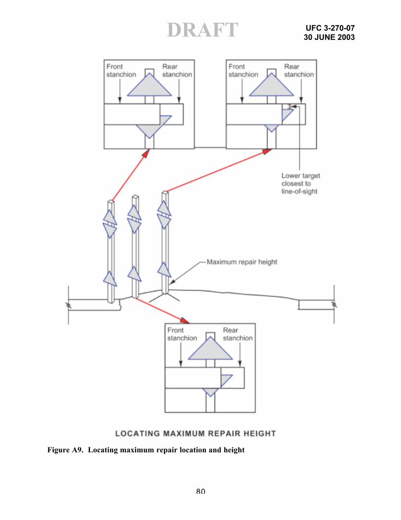
UFC 3-270-0730 JUNE 2003
80
DRAFT
Figure A9. Locating maximum repair location and height

UFC 3-270-0730 JUNE 2003
81
DRAFT
Figure A10. Example of reading graduated stanchions to determine repair height

UFC 3-270-0730 JUNE 2003
82
DRAFT
Figure A11. Identification of sag sections using the target rod

UFC 3-270-0730 JUNE 2003
83
DRAFTAPPENDIX B
EQUIPMENT AND MANPOWER REQUIREMENTS
Note: Equipment and manpower requirements vary by branch of service, type of unit,and the number of repair team members assigned. The following listing identifiesthe types of equipment and manpower assets typically used in ADR.
B-1 ARMY. Airborne and Air Assault engineer units have the bravado capabilityof repairing airfields to obtain a required MOS during forcible entry operations. Theyaccomplish this mission through the installation of an air-transportable ADR kit. Thisexpedient pavement repair kit was developed to provide all the materials and non-organic unit equipment required to repair one 7.6-m- (25-ft-) diam crater on either aconcrete- or asphalt-surfaced runway. To install this kit, Army units have developed aLight Airfield Repair Package (LARP) that is comprised of organic constructionequipment and the ADR kit. Note: All equipment in these packages is inserted eitherby Airborne (heavy drop) or Air Assault (external cargo helicopter loads) techniques.
B-1.1 CAPABILITIES:
(1) Airfield Assessment
(2) Spall and Crater Repair
(3) Limited Concrete Capability
(4) Limited Night Capabilities
B-1.2 COMPOSITION: Equipment included in the Army’s Airborne and Air AssaultLARPs is shown in Tables B-1 and B-2, respectively.
Table B1. Army Airborne LARP(Requires seven platforms via C-17 or C-130)
• 2.5 cubic yard front-end loader – one each• SEE (Small Emplacement Excavator) – one each• Dozer (Deployable Universal Combat Earthmover [DEUCE]) – one each• Single-drum vibratory compactor – one each• Dump truck – one each• ADR kit (FRP matting, sand-grids, miscellaneous tools) – two each• FAS (Forward Aerial Supply) Box - Includes additional sand-grid; water for
compaction; 50 repair parts from the Prescribed Load List (PLL) for LARPequipment; petroleum, oil, lubricants (POL) products; gas-powered handtampers; generator; and assorted miscellaneous hand tools

UFC 3-270-0730 JUNE 2003
84
DRAFTTable B2. Army Air Assault LARP
(Requires five lifts via CH-47D Chinook)
• 836G Bobcat with bucket – one each• 836G Bobcat with sweeper – one each• JD 450 dozer – one each• SEE – one each• ADR kit (FRP matting, sand grids, miscellaneous tools) – one each
B-1.3 Manpower requirements for a task organized engineer section are as follows:
• 1 OIC• 14 NCOIs/Equipment Operators• 2 Mechanics
B-2 NAVY/MARINE CORPS
B-2.1 Civil Engineer Support Equipment (CESE). For Navy crater repair units,most of the construction equipment is contained in Advanced Base FunctionalComponent (ABFC) P-36. Typically, ABFC P-36 is provided to an advanced naval airbase located in friendly territory for airfield damage repair (ADR). ABFC P-36 is alsoincluded with the ABFCs to be deployed with the Naval Construction Force (NCF)participating in the seizure, construction, and occupation of an advanced naval airbase in enemy territory. The ABFC P-36 ADR component contains the material andequipment required for repairing bomb craters using specified types of equipment forcrater cleanout, backfilling, grading, and compaction. FOD cover panels, emplacedover the repaired craters, are fabricated from the following:
• Prefabricated panels of AM-2 matting.• On-site-assembled FOD cover panels (FRP) prepared from prefabricated bolt-
together panels.
B-2.1.1 Basic earthmoving and compaction equipment is available in MarineWing Support Squadrons (MWSS) and Force Engineer Support Battalions. Craterrepair FOD cover material is configured in an ADR kit that contains FRP panels and allthe necessary ancillary hardware to field two large or four small mats.
B-2.1.2 If the ADR site is located at an existing friendly airfield having ABFC P-36component the assignment and distribution of CESE for ADR operations will bedependent on the amount of available equipment, the structure of the ADRorganization, and the number of people in the ADR organization. In fact, it is highlylikely that the Battalion will find that CESE availability is the major constraining factor indeveloping its ADR organization. Recommended CESE assignments are listed inTables B3 and B4 for main body/large DET and Air DET/small DET, respectively.

UFC 3-270-0730 JUNE 2003
85
DRAFTTable B3
Navy Recommended ADR CESE Distribution: NMCB Main Body/Large Detail
ADR CREW CESE ASSIGNMENT QUANTITY
ADR OIC/AOIC 3/4T Utility Truck 1 each
DAT Armored/Hardened Vehicle 1 each
Hauling Crew Chief 3/4T Utility Truck 1 each
Hauling Crew
Tractor w/35T Tilt Top TRLR15T Dump TruckLoader 4/1 Bucket6K LB RT Forklift or larger
5 each3 per crater crew2 per stock pile crew2 per every other crew
Crater Crew Chief 3/4T Utility Truck 1 each
Runway ClearingCrew
GraderTractor w/SweeperMagnetic Sweeper15T Dump TruckLoader 4/1 Bucket
5 per crew6 each2 eachShare with hauling crew3 each
Crater Repair Crew
Loader 4/1 BucketDozer (w/oracle blade)GraderCompactor, VibratoryLight Plant TrailerCompressor, 250 CFMConcrete SawCentrifugal Pump
2 per crew1 per crew1 per crew1 per crew2 per crew1 per crew1 per crew2 per crew
FOD Cover CrewUses Loaders from CraterRepair Crew6K LB RT Forklift or larger
1 per crew
Crater SupportCrew Chief
3/4T Utility Truck Share with crater crew
Spall Repair Crew
1T Pick-up Truck11S or Larger MixerWater TruckCompressor 150 CFM
2 per crew1 per crew1 per crew1 per crew
Cretemobile Crew
Cretemobile w/15T TractorLoader 4/1 Bucket6K LB RT ForkliftWater Distribution TruckTractor w/High Boy TRLR
1 per crew1 per crew1 per crew1 per crew1 per crew
MOS Lighting Crew1-1/4T TruckLight Plant TRLR
1 per crew1 per crew
MOS Marking Crew1-1/4T TruckLight Plant TRLR
1 per crew1 per crew
MAAS Installation 15T Tractor 1 per crew

UFC 3-270-0730 JUNE 2003
86
DRAFTNOTE: Actual number of pieces of CESE used should be tailored to the site.
Table B4Navy Recommended ADR CESE Distribution: NMCB Air Det/Small Det
ADR CREW CESE ASSIGNMENT QUANTITY
ADR OIC/AOIC 3/4T Utility Truck 1 each
DAT Armored Vehicle 1 each
Hauling Crew
Tractor w/35T Tilt Top TRLRDump TrucksForklift (6K or larger)Loader
1 each2 per crater crew2 each1 each
Runway ClearingCrew
GraderTractor w/SweeperMagnetic Sweeper
1 each1 each1 each
Crater Crew Chief 3/4T Utility Truck 1 each
Crater RepairCrew
LoaderDozerCompactor, VibratoryLight Plant TrailerCompressor, 250 CFMConcrete Saw
1 per crew1 per every other crew1 per crew1 per crew1 per crew1 per crew
FOD Cover Crew Uses the CESE of Crater Repair Crew
Spall Repair Crew2-1/2T Cargo Truck orPick-up Truck
1 per crew
Cretemobile Crew
Uses the CESE of Crater Repair Crewplus:Cretemobile w/TractorLoaderForkliftWater Distribution Truck
1 per crew1 per crew1 per crew1 per crew
MOS LightingCrew
1-1/4T Truck 1 per crew
MOS MarkingCrew
1-1/4T Truck 1 per crew
MAAS Installation Tractor 1 per crewNOTE: The actual number of pieces of CESE used should be tailored to the site.
Given these CESE distribution recommendations, the Battalion should develop itsADR organization based on both CESE and personnel availability.
B-2.2 Manning Levels. Manpower requirements for large (main body) and small (air)detachments are shown in Tables B5 and B6, respectively.

UFC 3-270-0730 JUNE 2003
87
DRAFT
Table B5Navy Recommended Main Body or Large DET ADR Manning
TITLE MANNING LEVEL
BTN Liaison Officer(Assigned to Station Command Center)
1
MOS Selection Team (2 Teams) Team Chief Selection Plotter Communicator
8
Damage Assessment TeamsMain Body – 4 Teams/Large DET – 3 teams Team Leader Team Members (2 ea)
MB 12LG DET 9
ADR OIC 1ADR AOIC 1Crater Crew Chief 1Crater Crew (5 Teams) Team Leader Equipment OP (4 ea) Laborer (3 ea)
40
FOD Cover Crew 1 – Concrete Slab Team Leader Equipment OP (4 ea) Laborer (3 ea)
8
FOD Cover Crew 2 – Bolted FRP Team Leader Laborer (14 ea)
15
FOD Cover Crew 3 – Folded FRP Team Leader Equipment OP (2 ea) Laborer (6 ea)
9
FOD Cover Crew 4 – AM-2 Matting Team Leader Laborer (14 ea)
15
FOD Cover Crew 5 – Cretemobile RSPC Placement Team Ldr Equipment OP (10 ea) Laborer (15 ea) Cretemobile Team Ldr
28

UFC 3-270-0730 JUNE 2003
88
DRAFT Equipment OP (1 ea) Additional FOD Cover Crew (As Required)
Table B5 (Continued)Navy Recommended Main Body or Large DET ADR Manning
TITLE MANNING LEVEL
Hauling Crew Chief 1
Hauling Crew Equipment OP (5 ea) Dump Truck OP (3 ea per Crater Crew)
30
Stock Pile Crew – 2 Front End Loaders per Stock Pile 2Crater Support Crew Chief 1Debris Clearing Crew Team Leader Equipment OP (13 ea)
14
Crater Support Crew Team Leader CM’s (2 ea)
3
Spall Repair Crew (as required) Team Leader Equipment OP (1 ea) Laborer (2 ea)
20
MOS Marking Crew Team Leader Equipment OP (1 ea) Laborer (1 ea)
3
MOS Lighting Crew Team Leader Laborer (5 ea)
6
MAAS Installation Crew Team Leader Laborer
2
Total manning level: Main Body 221, Large Det 218
Note: These manning levels are approximate.COMSECONDNCB/COMTHIRDNCBINST 3300.1 of 31 JAN 1994 states: TheBattalion’s ADR organization shall be developed in conjunction with and as part of theoverall Station BDR/ADR organization… In general, the ADR organization should field

UFC 3-270-0730 JUNE 2003
89
DRAFTthe hauling and runway clearing crews and as many crater repair crews as the on-siteCivil Engineer Support Equipment (CESE) and personnel will support.
Table B6Navy Recommended Air DET or Small DET ADR Manning
TITLE MANNING LEVEL
BTN Liaison Officer 1
ADR OIC 1
ADR AOIC 1
MOS Selection Team Team Chief Selection Plotter Communicator
4
Damage Assessment Team (2 Teams) Team Leader Team Members (2 ea)
6
Crater Crew Chief
Crater Crew (2 Teams) Team Leader Equipment OP (4 ea) Laborer (3 ea)
16
FOD Cover Crew 1 – Concrete Slab Team Leader Equipment OP (4 ea) Laborer (3 ea)
8
FOD Cover Crew 2 – Bolted FRP Team Leader Laborer (10 ea)
11
FOD Cover Crew 3 – Folded FRP Team Leader Equipment OP (2 ea) Laborer (6 ea)
9
FOD Cover Crew 4 – AM-2 Matting Team Leader Equipment OP (1 ea) Laborer (10 ea)
12
FOD Cover Crew 5 – Cretemobile RSPC Placement Team Ldr Laborer (13 ea)
18

UFC 3-270-0730 JUNE 2003
90
DRAFT Cretemobile Team Ldr Equipment OP (3 ea)Hauling Crew Equipment OP (1 ea) Dump Truck OP (2 ea per crater)
(Assume 10 craters)30
Table B6 (Cont’d)Navy Recommended Air DET or Small DET ADR Manning
TITLE MANNING LEVEL
Stock Pile Crew – 2 Front End Loaders per Stock Pile 2
Debris Clearing Crew Team Leader Equipment OP (5 ea)
2
Spall Repair Crew (2 Teams) Team Leader Equipment OP (1 ea) Laborer (2 ea)
8
MOS Marking Team Leader Laborer
2
MOS Lighting Crew Team Leader Laborer (5 ea)
6
MAAS Installation Crew Team Leader Laborer
1
TOTAL MANNING LEVEL: 136Note: These manning levels are approximate.COMSECONDNCB/COMTHIRDNCBINST 3300.1 of 31 JAN 1994 states: TheBattalion’s ADR organization shall be developed in conjunction with and as part of theoverall Station BDR/ADR organization. In general, the ADR organization should fieldthe hauling and runway clearing crews and as many crater repair crews as the on-siteCivil Engineer Support Equipment (CESE) and personnel will support.
B-3 Air Force. An ADR equipment set is a standardized set of equipment andvehicles that enables Air Force civil engineers to conduct ADR. There are threefielded ADR sets. The sets are graduated in a building-block manner to provide adesignated crater repair capability.
B-3.1 Traditional Airfield Damage Repair Equipment
B-3.1.1 Basic (R-1) Set. The R-1 Set listed in Table B7 supports the repair of threebomb craters (15 m [50 ft] in diameter) with AM-2 matting and/or FFM in four hours.

UFC 3-270-0730 JUNE 2003
91
DRAFTBasic sets are currently in place at most theater locations and contain 59 items ofvehicles/construction equipment (e.g., front-end loaders, dump trucks, excavators)and additional supplemental items (flood lights, spall repair material, AM-2, FFMmats).
B-3.1.2 Supplemental (R-2) Set. The R-2 Set listed in Table B8 contains 26 itemsof additional vehicles and equipment which are additive to the R-1 set and gives thecapability to repair six craters in four hours.
B-3.1.3 Supplemental (R-3) Set. The R-3 Set listed in Table B9 contains 18 piecesof additional vehicles and equipment that, when combined with the R-1 and R-2 sets,enables six repair teams to accomplish 12 crater repairs in four hours. Only a fewmain operating bases have the R-3 package in-place.
B-3.2 Personnel. Figure B1 illustrates a typical ADR organization predicated onthe use of the combined R-1 and R-2 equipment and vehicle packages. In a situationthat dictates the use of the full R-1 through R-3 equipment and vehicle packages,present Prime BEEF planning and force employment concepts envision that two 55-person lead team (UTC 4F9EA) and two 42-person follow teams (UTC 4F9EB) beused. While the full 194-person engineer complement will not be employed solely inthe ADR role, a majority of the personnel will be dedicated to this tasking.
Table B7U.S. Air Force R-1 Vehicle and Equipment Set
Vehicles Quantity
Excavator 3Grader 3Dozer (T-7) 3Front-End Loader (4-cy) 6Front-End Loader (2.5-cy) 3Vibratory Roller 3Dump Truck (8-cy) 8Dump Truck (5-ton) 4Tractor (7.5-ton) 3Tractor (10-ton) 3Trailer (22-ton) 3Trailer (60-ton) 3Vacuum Sweeper 2Tractor Mounted Sweeper (ADR) 2Paint Machine (Part of MOSMS) 2HMMWV 2ADR Trailer 31,500-Gallon Water Truck 3Dolly Converter (8-ton) 3

UFC 3-270-0730 JUNE 2003
92
DRAFTBasic ADR Equipment Support Kit 1Basic ADR Airfield Lighting Kit 1AM-2 ADR FOD Cover Kit 3/6/9AM-2 Support Kit _Folded Fiberglass Mat FOD Cover Kit (Kit-A) 1Folded Fiberglass Mat FOD Cover Kit (Kit-B)—Anchoring Systems 2Spall Repair Kit 4Minimum Operating Strip Marking System (MOSMS) 1
Table B8U.S. Air Force R-2 Vehicle and Equipment Set Additives
Vehicles Quantity
Excavator 3Front-End Loader (4-cy) 3Front-End Loader (2.5-cy) 3Vibratory Roller 3Dump Truck (8-cy) 7HMMWV 4ADR Trailer 3Total Vehicle Requirement 26
Equipment Items QuantitiesFloodlight/Generator Set 6Generator Set (Diesel) 1
Table B9U.S. Air Force R-3 Vehicle Set Additives
Vehicles Quantities
Front-End Loader (4-cy) 4Dump Truck (8-cy) 7Vacuum Sweeper 2Dirt Sweeper (RRR) 5Total Vehicle Requirement 18
Additional Equipment Item QuantityFloodlight/Generator Set 6
B-3.3 Air Force Airborne Red Horse Capability. The U.S. Air Force is currentlydeveloping Airborne engineer units that will have the capability of repairing airfields toobtain a required MOS. These units will provide an engineering asset for theaterairfield repair missions, while Army, Marine Corps, or Special Operations Forces willcontinue to be tasked with forcible entry operations. The Air Force has developed an

UFC 3-270-0730 JUNE 2003
93
DRAFTair-transportable ADR kit, similar to the Army’s light engineer assets. To install thiskit, the Air Force units have developed a Mobile Airfield Repair Equipment Set(MARES) that is comprised of organic construction equipment and the ADR kit. Note:All equipment in these packages is inserted either by Airborne (heavy drop) or AirAssault (external cargo helicopter loads) techniques.

UFC 3-270-0730 JUNE 2003
94
DRAFTFigure B1. Typical ADR (R-2 or R-3 Set) Organization
B-3.3.1 CAPABILITIES:
(1) Airfield Assessment(2) UXO Clearance(3) Obstruction Demolition(4) Force Protection Construction(5) Installation of Expedient Airfield Lighting(6) Spall and Crater Repair(7) Limited Concrete Capability(8) Limited Night Capabilities
B-3.3.2 COMPOSITION: Equipment included in the Air Force’s Airborne MARES isshown in Table B-1 and personnel in Table B-2.
SRC(BCE)
AIRFIELDDATS
DCC(CHIEF of
OPS)
ADR OICADR NCOIC
MOS REPAIRTEAM CHIEF
SUPPORTTEAM CHIEF
TAXIWAYREPAIR
TEAM CHIEF
HAULINGTEAM
CREW 3CREW 2CREW 1CREW 3CREW 2CREW 1
MAASINSTALLATION
MOS LIGHTINGSPALL REPAIRMOS MARKINGFOD REMOVAL

UFC 3-270-0730 JUNE 2003
95
DRAFTTable B10. Air Force Airborne MARES
(Requires seven platforms via C-17 or C-130)
• CAT 277 Multi-Terrain Loaders – two each• CAT 420D IT Backhoe Loader – one each• IHI IC-45 Tracked Crawler Carrier – one each• IC-45 Tracked Combat Support Trailer – one each• Lightweight EOD Equipment - as needed• Lightweight Crash Rescue Equipment – as needed• FAS (Forward Aerial Supply) Box - Includes sand-grid; water for compaction;
repair parts from the Prescribed Load List (PLL) for MARES equipment;petroleum, oil, lubricants (POL) products; gas-powered hand tampers;generator; and assorted miscellaneous hand tools
Table B11. Air Force Airborne Minimum Personnel Flight for ADR(Requires five lifts via CH-47D Chinook)
• Readiness – 2 Personnel• Red Horse – 21 Personnel• EOD – 6 Personnel• Fire/Crash Rescue – 6 Personnel• Total Flight – 35 Personnel
APPENDIX C
UFC 3-270-0730 JUNE 2003
96
DRAFT
REFERENCES
GOVERNMENT PUBLICATIONS:
1. Joint Publications
Ref. 4: Unified Facilities Criteria (UFC) 3-260-02, Pavement Design for Airfields
Ref. 8a: Army Field Manual (FM) 5-430-00-1, Air Force Joint Pamphlet (AFJPAM)32-8013, Volume I, Planning and Design of Roads, Airfields, andHeliports in the Theater of Operations – Road Design
Ref. 8b: FM 5-430-00-2, AFJPAM 32-8013, Volume II, Planning and Design ofRoads, Airfields, and Heliports in the Theater of Operations – Airfield andHeliport Design
Ref. 11: TM 5-822-14, AFJMAN 32-1019, Soil Stabilization for Pavements
Ref. 13: FM 5-530, NAVFAC MO-330, AFJMAN 32-1034, Materials Testing
2. Air Force
Ref. 1: Engineering Technical Letter (ETL) 98-5: C-130 and C-17 Contingencyand Training Airfield Dimensional Criteria
Ref. 3: Technical Order (T.O.) 35E2-4-1: Repair Quality Criteria System for RapidRunway Repair
Ref. 4: Engineering Technical Letter (ETL) 97-9: Criteria and Guidance for C-17Contingency and Training Operations on Semi-Prepared Airfields
Ref. 12: Engineering Technical Letter (ETL) 02-19: Airfield Pavement EvaluationStandards and Procedures
3. Army
Ref. 9: Unified Facilities Criteria (UFC) 3-250-03, Design Standard PracticeManual for Flexible Pavements
Ref. 10: Engineering Research and Development Center, Geotechnical andStructures Laboratory, Airfields and Pavements Branch:http://pavement.wes.army.mil/
4. Navy/Marine Corps

UFC 3-270-0730 JUNE 2003
97
DRAFTRef. 5: Naval Air Systems Command Instruction (NAVAIRINST) 13800.12B,
Certification of Expeditionary Airfield AM-2 Mat Installations, AircraftRecovery Equipment, Visual/Optical Landing Aids, and Marking/LightingSystems
Ref. 6: Naval Air Systems Command (NAVAIR) 51-60A-1, Technical Manual,Handbook, AM-2 Airfield landing Mats and Accessories; Installation,Maintenance, Repackaging, & Illustrated Parts Breakdown
Ref. 7: Naval Air Warfare Center Aircraft Division Lakehurst (NAWCADLKE)-MISC-48J200-0011, Expeditionary Airfield AM-2 Mat CertificationRequirements

UFC 3-270-0730 JUNE 2003
98
DRAFTAPPENDIX D
BIBLIOGRAPHY
GOVERNMENT PUBLICATIONS:
1. Joint Publications
UFC 3-250-03, Standard Practice Manual for Flexible Pavements
TM 5-822-7, AFM 88-6 Chapter 8, Standard Practice for Concrete Pavements
TM 5-822-9, Repair of Rigid Pavements Using Epoxy Resin Grouts, Mortars, andConcretes
http://airfielddamagerepair.com/ (This joint service Web site is currently underdevelopment.)
2. Air Force
T.O. 35E2-5-1, Crushed-Stone Crater Repair and Line-Of-Sight ProfileMeasurement for Rapid Runway Repair
T.O. 35E2-3-1, Folded Fiberglass Mats for Rapid Runway Repair
ETL 97-9, Criteria and Guidance for C-17 Contingency and Training Operations onSemi-Prepared Airfields
Air Force publications are available online at http://www.e-publishing.af.mil/
Air Force ETLs are available online athttp://www.afcesa.af.mil/Publications/ETLs/default.html and (for CCB subscribers)http://www.ccb.org/html/home.html
Air Force T.O.’s are available online at (https://toindex-s.robins.af.mil/toindex/
Headquarters Air Force Civil Engineer Support Agency, Civil Engineering Division(HQ AFCESA/CESC), Pavements Program:http://www.afcesa.af.mil/Directorate/CES/Civil/Pavements/Pavements.htm
3. Army
Army Technical Manual (TM) 5-822-7, Air Force Manual (AFM) 88-6, Chapter 8,Standard Practice for Concrete Pavements
Army Training Circular (TC) 5-340, Air Base Damage Repair (Pavement Repair)

UFC 3-270-0730 JUNE 2003
99
DRAFTArmy CE Manuals: http://www.usace.army.mil/inet/usace-docs/armytm/
TM 5-822-14 Soil Stabilization for Pavements
4. Navy/Marine Corps
Naval Facilities Command (NAVFAC) P-80, Facility Planning Criteria for Navy andMarine Corps Shore Installations
NAVFAC P80.3, Facility Planning Factor Criteria for Navy and Marine Corps ShoreInstallations, Appendix E, Airfield Safety Clearances
Naval Air Systems Command Manual (NAVAIRMAN) 48J200-00-21, SubgradeRequirements for Expeditionary Airfields
NAVAIR 00-80T-115, Expeditionary Airfield NATOPS Manual
Navy/Marine Corps Runway Crater Repair Handbook
NAWCADLKE MISC-48J200-0021, Subgrade Requirements for ExpeditionaryAirfields
NAWCADLKE-DDR-48J200-0038, In-Plane Bow Repair Method
Navy/Marine Corps Web site – Under development
AM-2 Mat Repair Procedure # 1, Removal Rubber Buildup from AM-2 Utilizing theSodium Bicarbonate Blasting Process.
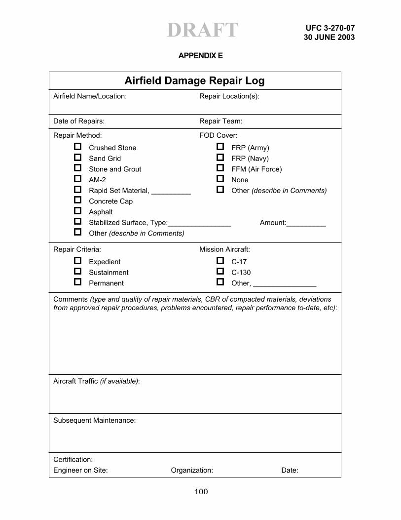
UFC 3-270-0730 JUNE 2003
100
DRAFTAPPENDIX E
Airfield Damage Repair LogAirfield Name/Location:
Date of Repairs: Repair Team:
Repair Method:
Crushed Stone
Sand Grid
Stone and Grout
AM-2
Rapid Set Material, __________
Concrete Cap
Asphalt
Stabilized Surface, Type:________________ Amount:__________
Other (describe in Comments)
Repair Criteria:
Expedient
Sustainment
Permanent
FOD Cover:
FRP (Army)
FRP (Navy)
FFM (Air Force)
None
Other (describe in Comments)
Mission Aircraft:
C-17
C-130
Other, ________________
Aircraft Traffic (if available):
Subsequent Maintenance:
Certification:
Engineer on Site: Organization: Date:
Comments (type and quality of repair materials, CBR of compacted materials, deviations from approved repair procedures, problems encountered, repair performance to-date, etc):
Repair Location(s):