airspeed and orifice size affect spray … and sprays, 22 (12): 997–1010 (2012) airspeed and...
TRANSCRIPT

Atomization and Sprays, 22 (12): 997–1010 (2012)
AIRSPEED AND ORIFICE SIZE AFFECTSPRAY DROPLET SPECTRA FROM ANAERIAL ELECTROSTATIC NOZZLE FORROTARY-WING APPLICATIONS
Daniel E. Martin1,∗ & James B. Carlton2
1Areawide Pest Management Research Unit, U.S. Department ofAgriculture–Agricultural Research Service (USDA-ARS), CollegeStation, Texas, USA
2Areawide Pest Management Research Unit, U.S. Department ofAgriculture–Agricultural Research Service (USDA-ARS), Brenham,Texas, USA
∗Address all correspondence to Daniel E. MartinE-mail: [email protected]
Original Manuscript Submitted: 09/20/2012; Final Draft Received: 04/02/2013
The aerial electrostatic spraying system patented by the U.S. Department of Agriculture–Agri-cultural Research Service (USDA-ARS) is a unique aerial application system that inductively chargesspray droplets for the purpose of increasing deposition and efficacy. While this system has many po-tential benefits, no published data exist that describe how changes in airspeed or nozzle orifice sizeaffect the droplet spectra of charged sprays at rotary-wing airspeeds. This study quantified these ef-fects in a controlled wind tunnel at airspeeds from 80 to 177 km/h. These tests were conducted atthe USDA-ARS Aerial Application Technology research facilities in College Station, Texas. Laserdiffraction data showed that increases in airspeed generally produced smaller spray droplets for allnozzle orifices tested, as quantified by standard spray droplet parameters. Generally, a decrease innozzle orifice size increased the fineness of the spray droplet spectra at all airspeeds but also increasedthe charge-to-mass ratio of the spray, which can improve spray deposition. The results from this studywill help aerial applicators better understand how changes in rotary-wing airspeeds and nozzle orificesize affect droplet size from aerial electrostatic nozzles.
KEY WORDS: electrostatic charging, helicopter, aerial application, aerial spray-ing, agricultural aviation, laser diffraction
1. INTRODUCTION
Recent increases in fuel prices have forced many aerial applicators to consider alterna-tive agricultural spray technologies that may be able to provide the needed deposition
1044–5110/12/$35.00 c© 2012 by Begell House, Inc. 997
998 Martin & Carlton
and efficacy at lower application rates. Aerial electrostatic spraying systems, includ-ing the system patented by the United States Department of Agriculture–AgriculturalResearch Service (USDA-ARS), described by Carlton (1999) and currently marketedby Spectrum Electrostatic Sprayers, Inc. (Dobbins, 2000), may provide such a bene-fit. Many aerial applicators around the world currently use this system; however, noknown data exist that describe its spray quality at rotary-wing airspeeds and associ-ated nozzle orifice sizes. Rotary-wing electrostatic aerial applicators need knowledgeof operational spray parameters to help them decide the best application airspeed andnozzle spray tip for the job. Over the past several decades, much foundational work hasbeen conducted to better understand electrical atomization and electrostatic chargingof spray particles for agricultural spray applications (Carlton and Isler, 1966; Thread-gill, 1973; Carlton, 1975; Carlton and Bouse, 1977, 1978, 1980; Inculet and Fischer,1989). Practical applications based on this improved understanding have led to fieldstudies using electrostatically charged sprays for both ground application (Herzog etal., 1983; Giles and Law, 1990; Giles and Blewett, 1991; Cooper et al., 1992, 1998;Giles et al., 1992; Maski and Durairaj, 2010) and aerial application (Cooper et al., 1992;Kihm et al., 1992; Carlton et al., 1995; Kirk et al., 2001; Fritz et al., 2007; Martin etal., 2007). In 2002, an initial field evaluation and uncharged droplet spectrum analy-sis of the original Spectrum aerial electrostatic system was conducted (Gordon et al.,2002) and only limited, field-collected droplet spectra data for this system at higher,fixed-wing airspeeds with water-sensitive papers has been reported (Fritz et al., 2007;Martin et al., 2007; Latheef et al., 2009). These four previous aerial studies used thesame charging system with similar atomization characteristics. Recently, the originalSpectrum aerial electrostatic nozzle was slightly redesigned and was the subject of thisstudy.
1.1 Objectives
The focus of this study was to evaluate the performance of the redesigned Spectrumaerial electrostatic nozzle (Spectrum Electrostatic Sprayers, Houston, Texas), which isreferred to here as the Brazilian aerial electrostatic nozzle. The objectives of the studywere as follows:
1. To quantify the effects of typical rotary-wing airspeeds and nozzle orifice sizes onthe atomization of charged spray from the Brazilian aerial electrostatic nozzle ina controlled wind tunnel.
2. To quantify the electrostatic performance characteristics (charge-to-mass ratio,Q/M ) of the nozzle for each of the test orifices and at each test airspeed/flowrate.
Atomization and Sprays

Airspeed and Orifice Size Affect Spray Droplet Spectra 999
2. MATERIALS AND METHODS
2.1 Electrostatic Nozzle Setup
All spray tests were conducted with the Brazilian electrostatic nozzle (Spectrum Elec-trostatic Sprayers, Houston, Texas). The nozzle was mounted to a test section of a slip-stream boom at the outlet of a high-speed wind tunnel (Fig. 1), positioned in the centerof the outlet. A high-voltage conductor connected the electrostatic nozzle electrode toa power junction, which also was connected to a high-voltage power supply (Univer-sal Voltronics Corp., White Plains, New York). The power supply was grounded to theframe of the wind tunnel and adjusted to provide a positive voltage of 6000 V to theelectrode ring and induce a negative charge on the spray. The positive terminal of aDC microammeter (Simpson, Lac du Flambeau, Wisconsin) was connected to a custom-designed, electrically isolated, Faraday cage, to measure the return spray current throughthe system to ground (Fig. 2).
2.1.1 Atomization Testing
The atomization tests were conducted in the USDA-ARS Aerial Application Technol-ogy high-speed wind tunnel in College Station, Texas, which has an operational range
FIG. 1: Wind tunnel setup for the study showing: (a) wind tunnel outlet, (b) aerial elec-trostatic nozzle, (c) high-voltage conductor, (d) power junction, (e) test section of slip-stream boom, and (f) charging electrode (inset: spray tip within the charging ring).
Volume 22, Number 12, 2012
1000 Martin & Carlton
FIG. 2: Study setup showing: (a) aerial electrostatic nozzle, (b) laser diffraction instru-ment for measuring droplet size, (c) Faraday cage for capturing and returning spraycurrent, (d) computer system for processing data, and (e) high-voltage power supply.
of 24–346 km/h. The nozzle was tested at airspeeds of 80–177 km/h, and nozzle ori-fice diameters of 1.04–1.32 mm (TXVK-4, TXVK-6, and TXVK-8 spray tips; SprayingSystems Co., Wheaton, Illinois) were chosen for this study because they are specificallysuited to rotary-wing aircraft. A 50-mesh screen filter with a 138-kPa integrated checkvalve was used with the TXVK-4 and TXVK-6 spray tips while a 24-mesh screen fil-ter with a 138-kPa integrated check valve was used with the TXVK-8 spray tip. Thispractice is common because the smaller mesh size used on the TXVK-4 and TXVK-6helps reduce nozzle plugging of these smaller orifices from foreign materials. All spraytesting was completed at 517 kPa using a spray solution of water plus a non-ionic surfac-tant [0.25% volume-to-volume (v/v) ratio; R-11, Wilbur-Ellis, Devine, Texas] dispensedfrom an 18.9-L pressure pot (Model 29749PS, Sharpsville Container, Sharpsville, Penn-sylvania). Droplet size measurements were made using a Sympatec helium–neon laseroptical system (HELOS) (Clausthal-Zellerfeld, Germany) laser diffraction instrumentwith an R5 lens, a 13-mm beam diameter, and measurement range of 0.1–875µm. Thenozzle was positioned 53 cm from the laser beam and 79 cm from the mouth of the Fara-day cage. Pressure was first applied to the nozzle until steady-state plume conditionswere achieved and then analyzed with the laser for 10 s. A minimum of three replicatedmeasurements was made for each treatment.
Atomization and Sprays
Airspeed and Orifice Size Affect Spray Droplet Spectra 1001
2.1.2 Charge-to-Mass Ratio Determination
The charge-to-mass ratio of the spray was calculated for each of the spray tips at each ofthe tested airspeeds according to the following equation:
Q
M=
I
ML
(1)
whereQ/M = charge-to-mass ratio (mC/kg);I = measured return spray current (µA);and ML = liquid mass flow rate (g/s). The spray current with a charging voltage of+6000 V was measured for 60 s with the microammeter previously described. The spraymass flow rate was determined by collecting spray discharge from the nozzle for eachtip size at 517 kPa for 60 s. The collected spray was then weighed on a tared and cali-brated electronic digital balance (Model SK-5001WP, A&D Engineering, Inc., San Jose,California). These measurements were replicated three times and the flow rates wereaveraged for the three replicates.
2.2 Statistical Analyses
To test the significance of the airspeed and nozzle orifice size on the spray droplet spec-trum parameters, both the airspeed and nozzle orifice size were treated as fixed effects.The Statistical Analysis System, General Linear Model (PROC GLM, SAS Institute,Cary, North Carolina) was used to perform the analyses of variance and to test the sig-nificance of each effect at theα = 0.05 level of significance according to Duncan’s mul-tiple range test. If the probability of significance (p-value) was less than 0.05 or less than0.01, the effect was determined to be significant or highly significant, respectively.
For each of the graphs in the results section, statistically significant separation ofmeans are indicated by a combination of upper and lower case letters. The upper caseletters represent differences in the dependent variable between nozzle orifice sizes andthe lower case letters represent differences between airspeeds. For instance, if the dropletsize for the TXVK-4 nozzle orifice at 130 km/h is statistically different than that of theTXVK-6 nozzle orifice at the same airspeed, the TXVK-4 data point might have an uppercase A next to it on the graph and the TXVK-6 data point might have an upper case Bnext to it. In addition, for a given nozzle orifice size, if the droplet size at 110 km/his statistically different than at 130 km/h, the data point at 110km/h might be lowercase a, whereas the data point at 130 km/h might be lower case b. Putting these twostatistically significant indicators together, a data point may be labeled Aa and anothermay be labeled Ba. If these points are at a particular airspeed for different nozzle orificesizes, the labels would indicate a significant difference between the two points (i.e.,A versus B). However, if these two points are for a particular nozzle orifice size butat different airspeeds, the labels would indicate no significant difference between thetwo points, since both are designated with a lower case a. This method of indicating
Volume 22, Number 12, 2012
1002 Martin & Carlton
statistical separation of means is very useful when two different dependent variables arejointly considered.
3. RESULTS AND DISCUSSION
3.1 Charge-to-Mass Ratio
One of the most important parameters for determining electrostatic spray nozzle per-formance is the charge-to-mass ratio. Charge-to-mass (Q/M ) ratios with magnitudes onthe order of 1.0 mC/kg or greater have been found necessary to achieve enhanced spraydeposition from electrostatic ground sprayers (Law and Lane, 1981). Specifically, theelectric field within a falling electrostatically charged spray plume does not reach suffi-cient driving force to enhance deposition until the magnitude of the averageQ/M ratioreaches a value of about 1.0 mC/kg. TheQ/M ratios for the Brazilian aerial electrostaticnozzle were determined for various orifice sizes and rotary-wing airspeeds at a chargingvoltage of +6000 V. The results are presented in Table 1. Overall, as the orifice size de-creased, theQ/M ratio increased (P< 0.0001). This is expected as a lower mass of sprayflows through the nozzle with smaller orifices at the same charging voltage. In addition,for all orifice sizes, as airspeeds increased so did theQ/M ratios (P< 0.0001). This islikely attributed to a reduction in droplet size (and mass) at higher airspeeds due to in-creased air shear while the droplets still maintain the same charge. A reduction in nozzleorifice size also increased theQ/M ratio for all airspeeds (P< 0.0001). The higherQ/Mratios are desirable because they will favor increased deposition of the spray onto planttargets. Thus, higher application airspeeds would be desirable and should increase spraydeposition. It is also important to realize that in an aerial application system, the spray istypically released 2–4 m above the plant canopy. As the droplets fall from their releasepoint to their target, depending primarily upon temperature and relative humidity, theywill lose mass due to evaporation. This will increase theQ/M ratio of the droplets at thetime of impact, resulting inQ/M ratios higher than those listed in Table 1.
TABLE 1: Spray charge-to-mass ratio (mC/kg) from a Brazilian aerial electrostaticnozzle at rotary-wing airspeeds with +6000 V applied voltage
Nozzle Flow Rate (g/s)Airspeed (km/h)
80 113 145 177TXVK-4 4.94 –0.648 Aa –0.850 Ab –0.972 Ac –1.114 AdTXVK-6 7.01 –0.500 Ba –0.714 Bb –0.828 Bc –0.928 BdTXVK-8 8.87 –0.394 Ca –0.575 Cb –0.789 Cc –0.845 Cd
Note: The spray solution was water plus 0.25% v/v non-ionic surfactant. Means followedby the same letter are not significantly different based on Duncan’s multiple range test withα = 0.05. Differences within a column are designated by an upper case letter; differenceswithin a row are designated by a lower case letter.
Atomization and Sprays
Airspeed and Orifice Size Affect Spray Droplet Spectra 1003
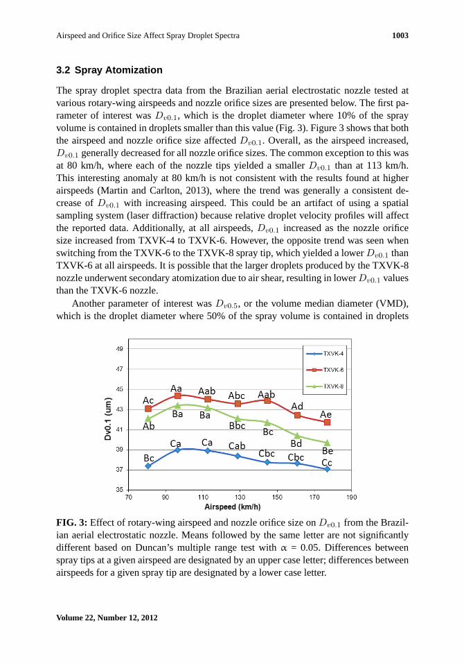
3.2 Spray Atomization
The spray droplet spectra data from the Brazilian aerial electrostatic nozzle tested atvarious rotary-wing airspeeds and nozzle orifice sizes are presented below. The first pa-rameter of interest wasDv0.1, which is the droplet diameter where 10% of the sprayvolume is contained in droplets smaller than this value (Fig. 3). Figure 3 shows that boththe airspeed and nozzle orifice size affectedDv0.1. Overall, as the airspeed increased,Dv0.1 generally decreased for all nozzle orifice sizes. The common exception to this wasat 80 km/h, where each of the nozzle tips yielded a smallerDv0.1 than at 113 km/h.This interesting anomaly at 80 km/h is not consistent with the results found at higherairspeeds (Martin and Carlton, 2013), where the trend was generally a consistent de-crease ofDv0.1 with increasing airspeed. This could be an artifact of using a spatialsampling system (laser diffraction) because relative droplet velocity profiles will affectthe reported data. Additionally, at all airspeeds,Dv0.1 increased as the nozzle orificesize increased from TXVK-4 to TXVK-6. However, the opposite trend was seen whenswitching from the TXVK-6 to the TXVK-8 spray tip, which yielded a lowerDv0.1 thanTXVK-6 at all airspeeds. It is possible that the larger droplets produced by the TXVK-8nozzle underwent secondary atomization due to air shear, resulting in lowerDv0.1 valuesthan the TXVK-6 nozzle.
Another parameter of interest wasDv0.5, or the volume median diameter (VMD),which is the droplet diameter where 50% of the spray volume is contained in droplets
FIG. 3: Effect of rotary-wing airspeed and nozzle orifice size onDv0.1 from the Brazil-ian aerial electrostatic nozzle. Means followed by the same letter are not significantlydifferent based on Duncan’s multiple range test withα = 0.05. Differences betweenspray tips at a given airspeed are designated by an upper case letter; differences betweenairspeeds for a given spray tip are designated by a lower case letter.
Volume 22, Number 12, 2012

1004 Martin & Carlton
smaller than this value. Again, from this parameter it can be seen that the VMD of thespray generally decreased with increasing airspeed for all nozzle orifices except for theTXVK-8 nozzle at 80 km/h (Fig. 4). In addition, overall, as the nozzle orifice size in-creased, the VMD also increased, except for the TXVK-8 nozzle at 80 km/h, which had asmaller VMD than the TXVK-6 nozzle at the same airspeed (121.14 versus 124.51µm).Interestingly, the VMD values for the TXVK-4 orifice were much lower than those forthe TXVK-6 or TXVK-8 orifice at all airspeeds. The VMD values for TXVK-6 andTXVK-8 were virtually identical for airspeeds below 129 km/h, and only nominally dif-ferent from 129 to 177 km/h. The overall trend for the VMD as a function of airspeedand orifice size agrees with previously published fixed-wing data for the same nozzle(Martin and Carlton, 2013).
Analysis ofDv0.9, which is the droplet diameter where 90% of the spray volume iscontained in droplets smaller than this value, indicated a similar trend where increasesin airspeed generally resulted in a decrease inDv0.9 of the spray for all orifice sizes,with stronger trends as the airspeed increased (Fig. 5). Additionally, an increase in noz-zle orifice size generally resulted in an increase inDv0.9 for all airspeeds. Significantdifferences betweenDv0.9 of the TXVK-6 and TXVK-8 orifices were only seen above113 km/h, whereasDv0.9 of TXVK-4 was much smaller than both the TXVK-6 and
FIG. 4: Effect of airspeed and nozzle orifice size onDv0.5 from the Brazilian aerialelectrostatic nozzle. Means followed by the same letter are not significantly differentbased on Duncan’s multiple range test withα = 0.05. Differences between spray tips at agiven airspeed are designated by an upper case letter; differences between airspeeds fora given spray tip are designated by a lower case letter.
Atomization and Sprays
Airspeed and Orifice Size Affect Spray Droplet Spectra 1005
FIG. 5: Effect of airspeed and nozzle orifice size onDv0.9 from the Brazilian aerialelectrostatic nozzle. Means followed by the same letter are not significantly differentbased on Duncan’s multiple range test withα = 0.05. Differences between spray tips at agiven airspeed are designated by an upper case letter; differences between airspeeds fora given spray tip are designated by a lower case letter.
TXVK-8 orifices at all airspeeds. These results forDv0.9 are consistent with previouslypublished results for this nozzle at higher airspeeds (Martin and Carlton, 2013).
The relative span (RS) of a spray is defined as
RS=(Dv0.9 −Dv0.1)
Dv0.5(2)
For aerial spray applications, a lower RS is usually desirable because the range of dropletsizes is minimized. However, a lower RS is only advantageous if the most efficaciousdroplet spectrum is known for the target pest. When the required droplet spectrum is notknown or if multiple pests are targeted, each with a different optimum droplet spectrum,a larger RS may be desired. In this study, the RS of the spray did not follow a consistentpattern (Fig. 6). For the TXVK-4 orifice, the RS generally decreased as the airspeed in-creased, for all airspeeds. The opposite trend resulted from the TXVK-8 orifice becauseit remained unchanged for airspeeds between 80 and 129 km/h; however, it generallyincreased at airspeeds between 145 and 177 km/h. The airspeed had very little effecton the RS of the TXVK-6 orifice. Above 129 km/h, the RS resulting from the TXVK-8nozzle was much greater than that of the TXVK-4 or TXVK-6 orifice.
Volume 22, Number 12, 2012
1006 Martin & Carlton
FIG. 6: Effect of airspeed and nozzle orifice size on the RS from the Brazilian aerialelectrostatic nozzle. Means followed by the same letter are not significantly differentbased on Duncan’s multiple range test withα = 0.05. Differences between spray tips at agiven airspeed are designated by an upper case letter; differences between airspeeds fora given spray tip are designated by a lower case letter.
One of the most important spray droplet spectra parameters for determining the po-tential driftability of a spray is the percent of the spray volume that is contained in fines.This fraction of the spray is usually reported as the percentage of the spray volume thatcontains 100–200µm droplets or less (Yates et al., 1976; Miller, 1993; Hoffmann andKirk, 2005; Fritz et al., 2010; Martin and Carlton, 2013). In this study, we report the per-cent volume of the spray that contains droplets of 100µm or less, which shall henceforthbe referred to as percent fines. From Fig. 7, it can be seen that the percent fines gener-ally increased as the airspeed increased for all nozzle orifices with the exception of theTXVK-4 orifice at 80 km/h, where the percent fines at this point were slightly higher thanat 97 km/h. Also, as the nozzle orifice size increased from the TXVK-4 nozzle orificeto the TXVK-6 orifice, the percent fines decreased. However, there was no difference inpercent fines between the TXVK-6 and TXVK-8 orifices, except at 177 km/h, where theTXVK-6 orifice resulted in a slightly higher percentage of fines (45.14 versus 44.11%).The overall trend of a general increase in percent fines with decreasing orifice size andincreasing airspeed is consistent with previous research at higher airspeeds (Martin andCarlton, 2013). For a conventional aerial nozzle, anything over about 10% driftable fineswould be of great concern because the spray would have the drift potential of a mediumor finer spray, whereas coarse sprays are usually preferable when drift is a concern. With
Atomization and Sprays
Airspeed and Orifice Size Affect Spray Droplet Spectra 1007
FIG. 7: Effect of airspeed and nozzle orifice size on percent fines (percent of the sprayvolume that is contained in spray droplets of 100µm or less) from the Brazilian aerialelectrostatic nozzle. Means followed by the same letter are not significantly differentbased on Duncan’s multiple range test withα = 0.05. Differences between spray tips at agiven airspeed are designated by an upper case letter; differences between airspeeds fora given spray tip are designated by a lower case letter.
electrostatic nozzles, the smaller the droplet, the higher is the charge-to-mass ratio, andthus, the greater the attraction between droplet and target. Depending on the height abovecanopy at the time of application, the result will be either deposition of the spray onto theplant surface or off-target movement of the spray due to wind. The distance between thedroplet and target would be the determining factor whether deposition or drift occurs.
4. CONCLUSIONS
This study quantified the effects of typical rotary-wing airspeeds and nozzle orifice sizeson the atomization of charged spray from a Brazilian aerial electrostatic nozzle in acontrolled high-speed wind tunnel. Without exception, increases in airspeed from 97 to177 km/h generally produced smaller spray droplets for all nozzle orifices tested. Addi-tionally, an increase in nozzle orifice size generally increased the VMD andDv0.9 butreduced the percent fines (% volume< 100µm) at all airspeeds. Increases in airspeedand reductions in nozzle orifice size also increased theQ/M ratio of the resulting spray,which should increase deposition on plant targets. These results agree well with previ-ously reported data for aerial electrostatic droplet spectra using the same nozzle at higher,
Volume 22, Number 12, 2012
1008 Martin & Carlton
fixed-wing airspeeds (Martin and Carlton, 2013). While it is currently difficult to corre-late the results of this study with actual in-field deposition, how these charged spraysinfluence efficacy, or the potential for these small-droplet sprays to drift, they lay thegroundwork for future research to improve this understanding. Future research shouldinvestigate the effects of airspeed and nozzle orifice size on the chargeability of differentspray formulations, quantify spray drift and deposition from electrostatically chargedsprays under field conditions, and compare the performance of a newly designed aerialelectrostatic nozzle to the current nozzle.
ACKNOWLEDGMENTS
The authors thank Dr. Bradley Fritz for use of the high-speed wind tunnel and Mr. ChrisParker for his valuable assistance in collecting and compiling the data.
DISCLAIMER
Mention of trade names or commercial products in this publication is solely for thepurpose of providing specific information and does not imply recommendation or en-dorsement by the U.S. Department of Agriculture. The USDA is an equal opportunityprovider and employer.
REFERENCES
Carlton, J. B., Electrical capacitance determination and some implications for an electrostaticspray-charging aircraft,Trans. ASAE, vol. 18, no. 4, pp. 641–644, 1975.
Carlton, J. B., Technique to reduce chemical usage and concomitant drift from aerial sprays,United States Patent No. 5,975,425, 1999.
Carlton, J. B. and Bouse, L. F., Distribution of the electric-field for an electrostatic spray chargingaircraft,Trans. ASAE, vol. 20, no. 2, pp. 248–257, 1977.
Carlton, J. B. and Bouse, L. F., Spray deposit sampling technique to evaluate electrostatic aerialspray-charging,Trans. ASAE, vol. 21, no. 1, pp. 1–5, 1978.
Carlton, J. B. and Bouse, L. F., Electrostatic spinner-nozzle for charging aerial sprays,Trans.ASAE, vol. 23, no. 6, pp. 1369–1378, 1980.
Carlton, J. B., Bouse, L. F., and Kirk, I. W., Electrostatic charging of aerial spray over cotton,Trans. ASAE, vol. 38, no. 6, pp. 1641–1645, 1995.
Carlton, J. B. and Isler, D. A., Development of a device to charge aerial spray electrostatically,Agric. Aviat., vol. 8, no. 2, pp. 44–51, 1966.
Cooper, J. F., Jones, K. A., and Moawad, G., Low-volume spraying on cotton: A comparisonbetween spray distribution using charged and uncharged droplets applied by two spinningdisc sprayers,Crop Protect., vol. 17, no. 9, pp. 711–715, 1998.
Atomization and Sprays
Airspeed and Orifice Size Affect Spray Droplet Spectra 1009
Cooper, S. C., Law, S. E., All, J. N., and Oetting, R. D. Air-assisted electrostatic sprays forapplications of environmentally-safe pesticides, ASAE Paper No. 92-1571, St. Joseph, MI:ASAE, 1992.
Dobbins, T., Texas aerial applicator tries electrostatic spray system,AgAir Update, vol. 18, no.5, pp. 24–25, 2000.
Fritz, B. K., Hoffmann, W. C., and Bagley, W. E., Effects of spray mixtures on droplet size underaerial application conditions and implications on drift,Appl. Eng. Agric., vol. 26, no. 1, pp.21–29, 2010.
Fritz, B. K., Hoffmann, W. C., Martin, D. E., and Thomson, S. J., Aerial application methods forincreasing spray deposition on wheat heads,Appl. Eng. Agric., vol. 23, no. 6, pp. 709–715,2007.
Giles, D. K. and Blewett, T. C., Effects of conventional and reduced-volume, charged-sprayapplication techniques on dislodgeable foliar residue of captan on strawberries,J. Agric. FoodChem., vol. 39, no. 9, pp. 1646–1651, 1991.
Giles, D. K., Blewett, T. C., Saiz, S. G., Welsh, A. M., and Kreiger, R. I., Foliar and nontargetdeposition from conventional and reduced-volume pesticide application in greenhouses,J.Agric. Food Chem., vol. 40, no. 12, pp. 2510–2518, 1992.
Giles, D. K. and Law, S. E., Dielectric boundary effects on electrostatic crop spraying,Trans.ASAE, vol. 33, no. 1, pp. 2–7, 1990.
Gordon, B., Nicholls, J., Dorr, G., Gavan, S., and Byrnes, M., Field evaluation and droplet spec-trum analysis for the spectrum electrostatic system for use in cotton, The Centre For PesticideApplication and Safety, The University of Queensland, Queensland, Australia, 2002.
Herzog, G. A., Lambert III, W. R., Law, S. E., Seigler, W. E., and Giles, D. K., Evaluation of anelectrostatic spray application system for control of insect pests in cotton,J. Econ. Entomol.,vol. 76, no. 3, pp. 637–640, 1983.
Hoffmann, W. C. and Kirk, I. W., Spray deposition and drift from two “medium” nozzles,Trans.ASAE, vol. 48, no. 1, pp. 5–11, 2005.
Inculet, I. I. and Fischer, J. K., Electrostatic aerial spraying,IEEE Trans. Ind. Appl., vol. 25, no.3, pp. 558–562, 1989.
Kihm, K. D., Kim, B. H., and McFarland, A. R., Atomization, charge, and deposition charac-teristics of bipolarly charged aircraft sprays,Atomization Sprays, vol. 2, no. 4, pp. 463–481,1992.
Kirk, I. W., Hoffmann, W. C., and Carlton, J. B., Aerial electrostatic spray system performance,Trans. ASAE, vol. 44, no. 5, pp. 1089–1092, 2001.
Latheef, M. A., Carlton, J. B., Kirk, I. W., and Hoffmann, W. C., Aerial electrostatic-chargedsprays for deposition and efficacy against Sweetpotato Whitefly (Bemisia Tabaci) on cotton,Pest Manage. Sci., vol. 65, pp. 744–752, 2009.
Law, S. E. and Lane, M. D., Electrostatic deposition of pesticide spray onto foliar targets ofvarying morphology,Trans. ASAE, vol. 24, no. 6, pp. 1441–1445, 1981.
Volume 22, Number 12, 2012
1010 Martin & Carlton
Martin, D. E. and Carlton, J. B., Airspeed and orifice size affect spray droplet spectrum from anaerial electrostatic nozzle for fixed-wing applications,Appl. Eng. Agric., vol. 29, no. 1, pp.5–10, 2013.
Martin, D. E., Lopez, J. D., Hoffmann, W. C., Fritz, B. K., and Lan, Y., Field evaluation ofspinosad aerial applications for thrips control on cotton,Southwest. Entomol., vol. 32, no. 4,pp. 221–228, 2007.
Maski, D. and Durairaj, D., Effects of charging voltage, application speed, target height, andorientation upon charged spray deposition on leaf abaxial and adaxial surfaces,Crop Protect.,vol. 29, pp. 134–141, 2010.
Miller, P. C. H., Spray drift and its measurement, inApplication Technology for Crop Protection,G. A. Mathews and E. C. Hislop, eds., Wallingford, Oxon, U.K.: CAB International, pp. 101–122, 1993.
Threadgill, E. D., Evaluation of aerial electrostatic spray charging equipment,Technical Bul-letin 65, Agricultural and Biological Engineering Department, Mississippi Agricultural andForestry Experiment Station, Mississippi State University, Starkville, MS, 1973.
Yates, W. E., Akesson, N. B., and Bayer, B., Effects of spray adjuvants on drift hazards,Trans.ASAE, vol. 19, no. 1, pp. 41–46, 1976.
Atomization and Sprays