akd ethernet ip cyclic i/o assembly and explicit messaging ... · compactlogix, and contrologix. if...
TRANSCRIPT

1
AKD Ethernet IP Cyclic I/O Assembly and Explicit Messaging Rev. D 2/7/2017
In this application note, we’ll demonstrate the different command types supported by the AKD Ethernet
IP drive. While the PLC screenshots demonstrate using an Allen Bradley PLC ( Compactlogix in this case )
the methods are not AB specific but part of the Ethernet IP protocol using the AKD Ethernet IP drive. We
have not tested nor officially support other Ethernet IP masters beyond Micrologix1400 ( explicit only ),
Compactlogix, and Contrologix. If your master supports cyclic I/O Assembly Messenging and you are able
to map and establish communications, then this document will likely assist in understanding how to
accomplish similar tasks that our AOIs for AB perform. Again we do not guarantee compatibility except
for the AB PLCs listed. If you are using Compactlogix or Contrologix, this application note may help you
understand how the AKD Ethernet IP Communications ( and AOIs ) work behind the scenes. After
covering cyclic messaging, examples of a read and write parameter via explicit messaging will be given.
Various commands and functions:

2
This application note will cover:
• Cyclic messaging
1. Command Type 0x05 Torque
2. Command Type 0x06 Position Move
3. Command Type 0x07 Jog Move
a. In velocity mode
b. In position mode
4. Command Type 0x08 Velocity Setpoint
5. Command Type 0x1B Set Attribute of Position Controller Object
6. Get Attribute method
7. Command Type 0x1F
a. Read Parameter
b. Write Parameter
8. Homing Method
9. Running A Stored Motion Task Sequence
• Explicit Messaging
10. Read Parameter via Explicit Messaging
11. Write Parameter via Explicit Messaging

3
Foreword about Cyclic Messaging
In the case of using the AB Compactlogix for this application note, the sample project available on the
Kollmorgen website was used. To access the I/O assemblies it is important to understand how the
structure and controller tags are declared.
The AKD is setup as a Generic Ethernet Module where you give it a Name ( in this case AKD_1 ) and
setup the Connection Parameters ( Note the 64 byte size of both Input and Output ).
Depending on the PLC used will determine how these bytes are accessed.
In the case of the AB Compactlogix, the sample project has in Rung 0 of the ladder, the AKD_Drive
Communication AOI which updates the I/O Cyclic Assemblies with data on every scan. Controller tags
are created under the Axis_Internal name of the AKD_Drive AOI ( in this case “AXIS_ONE” ).
4
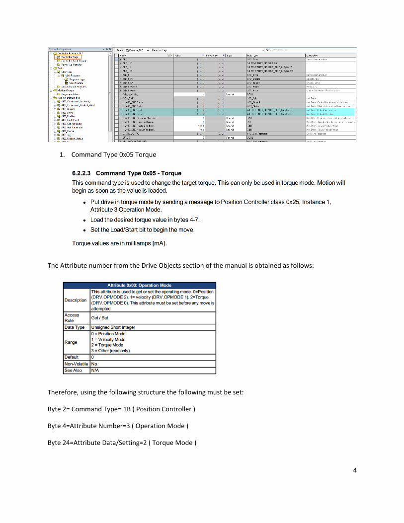
1. Command Type 0x05 Torque
The Attribute number from the Drive Objects section of the manual is obtained as follows:
Therefore, using the following structure the following must be set:
Byte 2= Command Type= 1B ( Position Controller )
Byte 4=Attribute Number=3 ( Operation Mode )
Byte 24=Attribute Data/Setting=2 ( Torque Mode )

5
Note the mode numbers in attribute 0x03 do not coincide with the convention used with the
DRV.OPMODE or displayed on the front of the AKD ( i.e. o0=torque mode, o1=velocity mode,
o2=position mode ).

6
On Load/Start the drive changes to Fieldbus and Torque Mode. Note Torque Mode via the position
controller is the only time with Ethernet IP the DRV.COMMANDSOURCE will change to/use “Fieldbus”. In
most other applications and commands the DRV.COMMANDSOURCE will be “Service”.
The AKD_Drive block moves the (axis_name).Control bits to the (axis_name).Output.Data so in order to
use the control word manually, the following was used. Shown in blue the Start Bit ( bit 0 ) is set to 1 to
trigger the command. If the drive is not SW Enabled, bit 7 ( Enable ) can be used as shown in the red box.
Using Workbench to verify the modal change:
Next to set the torque value in this mode, first turn the start bit in the control word off.

7
The command assembly is cleared from the previous command:

8
Next:
Set the torque value in bytes 4-7. Values are in mA ( i.e. 100 mA ).
Byte 2 is the command type which must be 0x05 for a Torque Move.
Once this is setup to execute and start the move, bit 0 ( start bit ) in the control word must be triggered.

9
Note the IL.CMDU is not used and the fieldbus writes directly to the IL.CMD.
To set a different setpoint, change the data in bytes 4-7 and then set the control word start bit to 0 and
then back to 1 for the new setpoint to take effect.
10
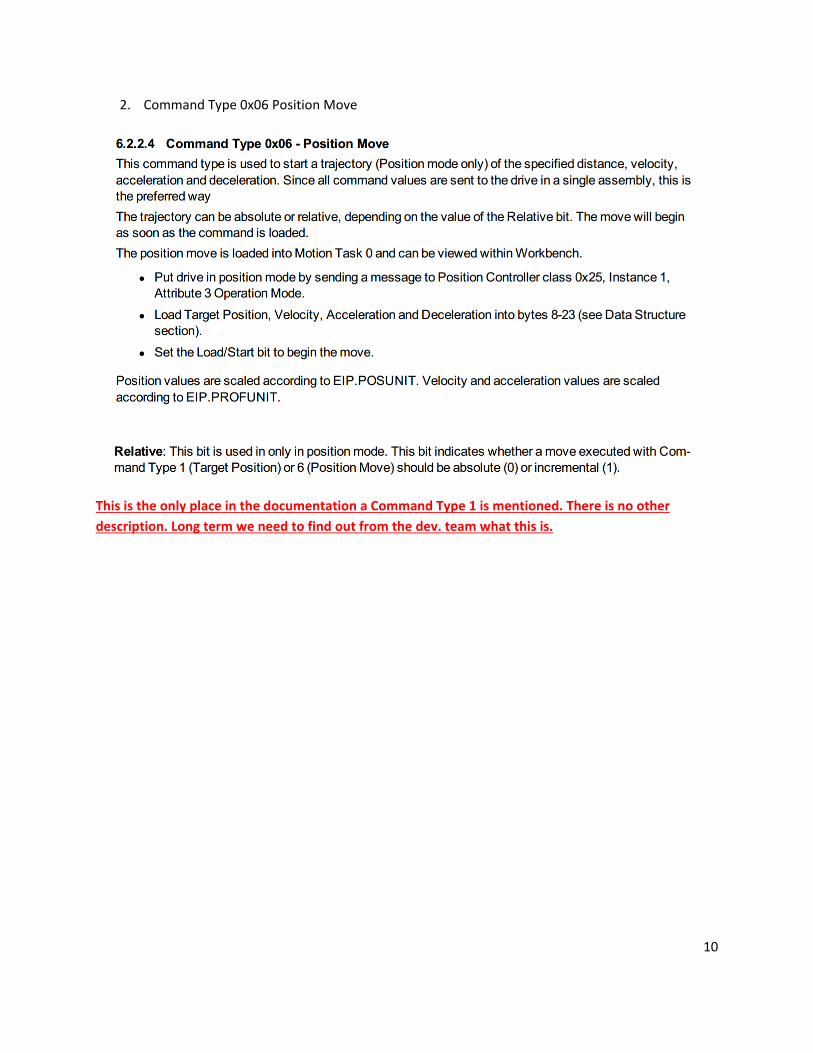
2. Command Type 0x06 Position Move
This is the only place in the documentation a Command Type 1 is mentioned. There is no other
description. Long term we need to find out from the dev. team what this is.

11
The Attribute number from the Drive Objects section of the manual is obtained as follows:
Therefore, using the following structure the following must be set:
Byte 2= Command Type= 1B ( Position Controller )
Byte 4=Attribute Number=3 ( Operation Mode )
Byte 24=Attribute Data/Setting=0 ( Position Mode )
Note the mode numbers in attribute 0x03 do not coincide with the convention used with the
DRV.OPMODE or displayed on the front of the AKD ( i.e. o0=torque mode, o1=velocity mode,
o2=position mode ).

12
To trigger the command, set the start bit in the control word ( bit 0 ) to 1.
If the drive is not enabled, the enable can be set by bit 7 in the control word shown in the red box.

13
Workbench should indicate the drive is in Service Position Mode and the display should show o2
( Position Mode ).
To setup the position move, the following profile was used. This application note assumes the default
Ethernet/IP units are used ( 65536=1 rev, 1rps, 1 rev/s^2 ).
Position
10 revs with the given scaling is 65536*10 or 655360 converted to hex is 0A 00 00.
Velocity
1 rps ( or 60 RPM ) is 65536 or converted to hex 01 00 00.

14
Accel/Decel
1000 rev/s^2 or 60000 rpm/s or 65536000 converted to hex is 03 E8 00 00
To setup the profile, the command assembly must be populated with the data above.
Recall:

15
Next choose whether the move is to be an absolute
In this application note, incremental ( relative ) is chosen.
After homing ( not shown here ) and on the trigger ( Load/Start bit, motion task 0 is loaded with values
and also executes.

16

17
3. Command Type 0x07 Jog Move
Note: This command works differently in velocity mode ( VL.CMD is set; homing is unnecessary )
than in position mode ( A repeating Motion Task 0 is used to perform the jog; homing is
necessary ).
a. In velocity mode
The following describes the steps required.
To put the drive in velocity mode by sending a message to the Position Controller per the first step,
the following steps must be executed.

18
The Attribute number from the Drive Objects section of the manual is obtained as follows:
Therefore, using the following structure the following must be set:
Byte 2= Command Type= 1B ( Position Controller )
Byte 4=Attribute Number=3 ( Operation Mode )
Note: The comment says “The command data for most command types” but note below for Bytes 24-31
it states “command data for Command Type 1B” which is the case here. This is confusing. Bytes 4-7 is
actually the “Attribute Number’ and Bytes 24-31 is the “Value of the Attribute”.
Byte 24=Attribute Data/Setting=1 ( Velocity Mode )

19
To execute the change of Operation Mode use the control word in Byte 0 to “Load”.
Checking via Workbench, the drive should be in Service and Velocity Mode.

20
Next, assuming the default Ethernet IP units of 65536 and a desired velocity of 600 rpm,
Velocity=10 rps ( 600 rpm )=65536*10=655360 which is “0A 00 00” hex.
Accel and Decel units of 65536 rev/s^2 and a desired accel/decel of 60000 rpm/s,
Accel=Decel=1000 rev/s^2 ( 60000 rpm/s ) =65536*1000=65536000 which is “03 E8 00 00” hex.
Set the command assembly for the given parameters above:

21

22
Next, per the control word, select a direction to jog in.
First I chose to jog negatively ( bit3=0 ):
The drive runs at -600 rpm.

23
Next I executed a Smooth Stop:
I cleared the load/start bit 0 and smooth stop bit 4 and then set the direction to 1 ( forward ) and then
retriggered the load/start bit 0. The drive jogs in the forward direction.
The drive runs at +600 rpm.
Note the VL.CMDU and VL.CMD both report the setpoint.
-->VL.CMDU
600.000 [rpm]
-->VL.CMD
600.000 [rpm]
-->

24
b. In position mode
In position mode, jogging is accomplished differently ( when the jog command type 07 is used ).
Changing to position mode via the position controller is in the same way already covered when changing
to velocity mode but the attribute data is 0 for position mode instead of 1 for velocity.
The drive should be in Service Position mode at this point.
Next the jog move is setup the same as in velocity mode with the velocity, accel, and decel in the
command assembly.
The direction bit in the control word works the same as previously described when jogging in velocity
mode. Note the drive must be homed before proceeding. A section on homing is given in this application
note and see the table of contents for the method. Assuming the drive is homed; With the direction bit
3 set to 0 ( reverse ) and on setting the load/start bit 0 to 1 jogging in the negative direction commences.

25
Note unlike in velocity mode, the VL.CMDU is not used but the VL.CMD is at the target velocity.
-->VL.CMD
-600.118 [rpm]
-->VL.CMDU
0.000 [rpm]
-->
Instead jogging is accomplished via Motion Task 0 as a repeating motion task.
I performed a smooth stop as before and then set the direction bit in the control word to 1 ( forward )
and then toggled the load/start bit from 1->0->1 and jogging in the forward direction commences.

26
4. Command Type 0x08 Velocity Setpoint
The chart below has the direction bit ( bit 3 ) high which is forward. This isn’t mentioned in the
description for command type 8 but it has an effect and in fact can be changed on the fly as well where
the drive will decelerate if running and then reverse in the opposite direction to the target speed set in
bytes 12-15.

27

28
It is possible to set the velocity, accel, and decel units via Ethernet IP as described but this application
note will assume the default value of 65536 is used.
The Object/Attribute writes to:
Next since the accel and decel in the command assembly are not used ( ignored ), the accel/decel must
be set either via the Position Controller or Workbench Terminal.
29
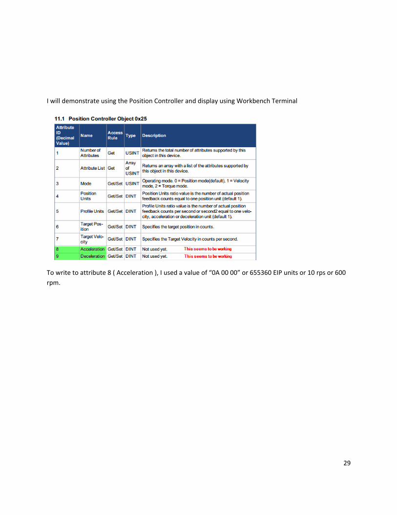
I will demonstrate using the Position Controller and display using Workbench Terminal
To write to attribute 8 ( Acceleration ), I used a value of “0A 00 00” or 655360 EIP units or 10 rps or 600
rpm.

30
To set the value, set the load/start bit ( bit 0 ) in the control word.
Repeat method for attribute 9: Deceleration.

31
As in previous methods uses the Position Controller attribute 3 to change the operation mode to
Velocity.
Enable drive via bit 7 of the control word.
Write 0x8 to the Command Type field (byte 2 ) in the command assembly.
To enable errors write a 0x14 in byte 3 of the command assembly and read the response in byte 3 of the
response assembly:

32
Response notes:
Per the above there is no current error.
Next set the velocity setpoint in bytes 12-15. In this case, the setpoint is hex “0a 00 00” or 655350 in EIP
units or 10 rps or 600 rpm.

33
Enable velocity setpoint following ( bit 0 of the command control word ).
The drive accelerates up to the target velocity and per the description for command type 8, as long as
the load/start bit is high, the velocity data in bytes 12-15 can be changed on the fly. As mentioned
before bit 3 ( direction ) can be changed on the fly as well.

34
5. Set Attribute
Set Attribute is specific to the Position Controller object. I arbitrarily chose attribute 3: Operation Mode.

35
Therefore, using the following structure the following must be set:
Byte 2= Command Type= 1B ( Position Controller )
Byte 4=Attribute Number=3 ( Operation Mode )
Byte 24=Attribute Data/Setting=0 ( Position Mode )
Note the mode numbers in attribute 0x03 do not coincide with the convention used with the
DRV.OPMODE or displayed on the front of the AKD ( i.e. o0=torque mode, o1=velocity mode,
o2=position mode ).
36
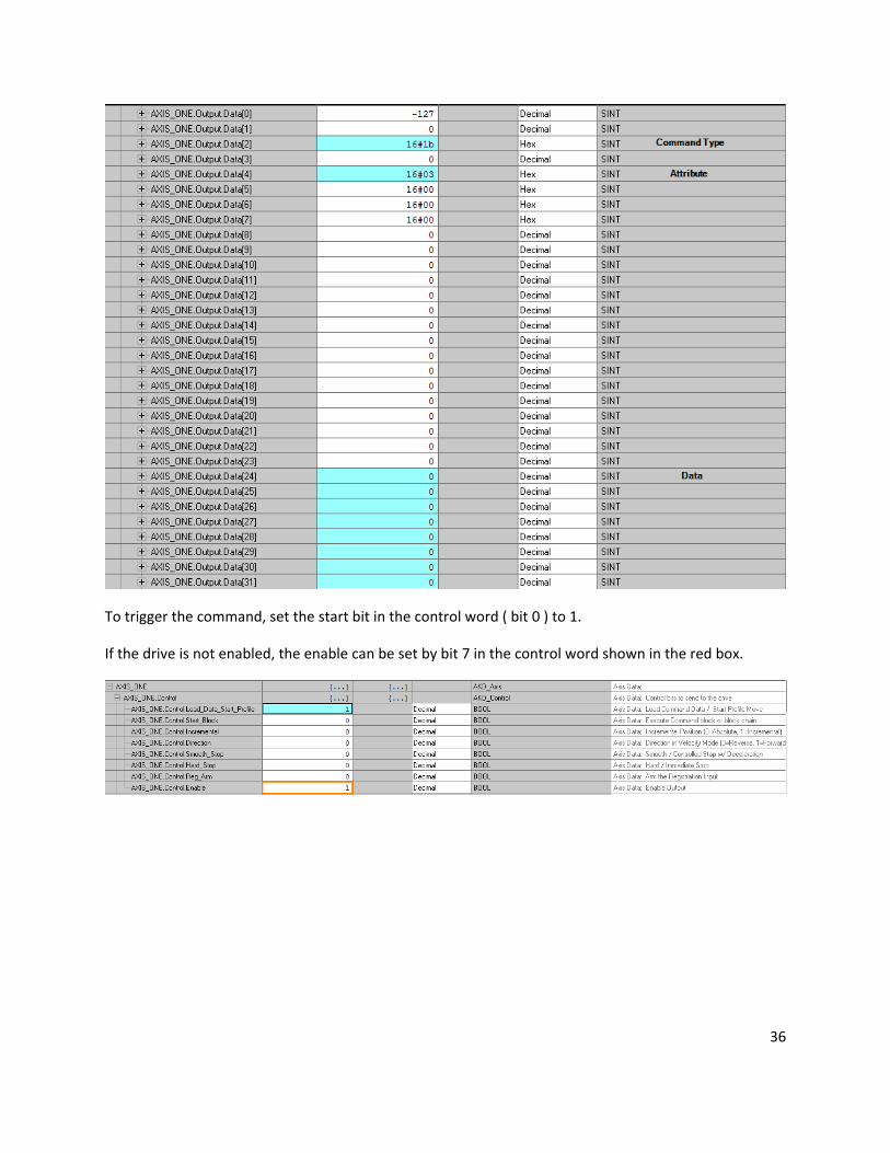
To trigger the command, set the start bit in the control word ( bit 0 ) to 1.
If the drive is not enabled, the enable can be set by bit 7 in the control word shown in the red box.

37
Workbench should indicate the drive is in Service Position Mode and the display should show o2
( Position Mode ).
6. Get Attribute:
Get Attribute is specific to the Position Controller. In this example I arbitrarily chose Home Mode
attribute 100 ( decimal ) and 64 ( hex ).

38
To test, I cleared byte 2 Command Type and set byte 32 to 64 ( Home Mode ).
The response came back as 7 which is correct ( Home Mode=7-Find zero angle ).

39
Per the definition if I change the mode via Workbench, byte 24 should update:

40
7. Write Parameter ( via polled IO command: static mapping )
Read Parameter ( via polled IO command: static mapping )
Both of these operations use the same command type 0x1F and byte 6 determines whether the
operation is a read or write. Note this is different than explicit messaging because this command
type uses the polled IO ( cyclic data ) of the command and response assemblies.

41
Don’t forget if you were using the Get Attribute field previously to clear it when using the Read
or Write Parameter command type.
To write a value, I chose the home velocity ( Home.V ) parameter.
I converted 211 to hex for Bytes 4 and 5 ( 211=D3 ):

42
I chose an arbitrary value to write: 12345 and converted it to hex: 3039

43
To write set the load/start bit in the control word from 0 to 1 ( transition ).
Read Parameter
To read the same parameter ( Home Distance ) I used the same command structure but set byte 6=0
( read ).

44
Set the load/start bit to 0 and then back to 1 to trigger the read.
The response assembly is:
From the Write Parameter data we know that 3038 hex is the value 12345 decimal.

45
8. Homing Method
Set Attribute has already been covered. In this case, let’s assume the Home mode has already been set
using that method or set via Workbench.
Homing Mode ( in this case mode 7: Find zero angle ):
We will also assume the drive is in Position Mode and enabled.

46
The definition is given as follows ( note the attribute ID in the chart above is decimal and the attribute ID
given here is hex ).
Recall the Set Attribute method.

47
To start the move ( trigger the command ) toggle the load/start bit from 0 to 1 in the control word.
Home move commences.
Per the description of the homing method, “when homing is complete the homed flag in Status Word 1
of the response assembly will be set”.

48

49
9. Running A Stored Motion Task Sequence
I created 2 Motion Tasks using Workbench. Suppose one is for the extend and the other is the return or
retracted move on a linear axis.

50
In the example, Motion Task 0 is the extend so, the Block# is set to zero in byte 1 of the command
assembly and bit 0 of the control word ( byte 0 ) is checked to be low ( 0 ).

51
To trigger the Motion Task, the start block ( bit 1 of byte 0; control word of the command assembly )
must be set to 1.
Once the move is complete the final commanded and feedback positions can be checked using
Workbench and you can see the target position of Motion Task 0 was reached.
The move I programmed was very fast but had I been monitoring Byte 1 ( Executing Block # ) of the
response assembly it would have displayed the currently executing “Block#” or “Motion Task”.
To execute the return move, I set the start block bit in the control word to 0.

52
Next I changed the Block # in Byte 1 of the command assembly.
To trigger, I set the Start Block bit in the control word to 1.
After the move was complete, I checked the final position in Workbench.

53
Explicit Messaging
Unlike the other command types previously covered which used the polled IO ( cyclic ) data of the
command and response assemblies, explicit messaging is independent of them and is “on demand”
meaning you have to send the message every time you want to read or write to a drive parameter.

54
To read or write a parameter using explicit messaging reference Appendix B: Parameter Listing where
each AKD Parameter is listed with its corresponding Ethernet IP Instance, Data Size, and Data Type. For
example:

55
To correlate this to the PLC the parameters listed are in the following formats:
Parameter Data Size Parameter Range Tag Data
Type
Tag Range
Command ( 1 byte ) 0 or 1 ( command will take any
data and be processed )
SINT -128 to +127
1 Byte Check Workbench Help for range
of each parameter
SINT -128 to +127
1 Byte Signed Check Workbench Help for range
of each parameter
SINT -128 to +127
2 Byte Check Workbench Help for range
of each parameter
INT -32768 to +32767
2 Byte Signed Check Workbench Help for range
of each parameter
INT -32768 to +32767
4 Byte Check Workbench Help for range
of each parameter
DINT -2147483648 to 2147483647
4 Byte Signed Check Workbench Help for range
of each parameter
DINT -2147483648 to 2147483647
8 Byte Check Workbench Help for range
of each parameter
LINT -9223372036854775808 To
9223372036854775807
8 byte Signed Check Workbench Help for range
of each parameter
LINT -9223372036854775808 To
9223372036854775807

56
The following will detail a write and read of the same data size.
Command Type ( 1 Byte ) Example: Clear Drive Faults
Per Appendix B:
The MSG block is given a name in the Message Control Tag and then click on the […] button beside it to
configure.
• Message Type-CIP Generic
• Service Type-Parameter Write ( this will populate the Service Code with 10 ( hex ) and Class f
( Hex ) and Attribute 1.

57
• A tag will need to be created to store the Source for the data which is the “Source Element”.
Click on the “New Tag…” button and define a tag with the SINT data type.
Select the “Source Length” to be the number of bytes per the parameter table ( in this case 1 Byte ).

58
Next click on the Communication tab of the MSG configuration.
Click on the “Browse…” button to search for the path.
In my case the screen looks as follows ( yours may be different ). I clicked on the given AKD axis ( in this
case the only one “ETHERNET-MODULE AKD_1”.

59
Click on the Tag tab. There is nothing to configure and the Message Control Tagname should be there.
Click Apply and then OK.
For the remainder of this application note, only the configuration of the read or write parameter screen
and declaration of the tag for the write or read data will be covered.

60
1 Byte Write ( non-command type ) by Explicit Messaging example

61
1 Byte Read

62
2 Bytes Write
2 Bytes Read

63

64
4 Bytes Write

65
4 Bytes Read

66
8 Bytes Write
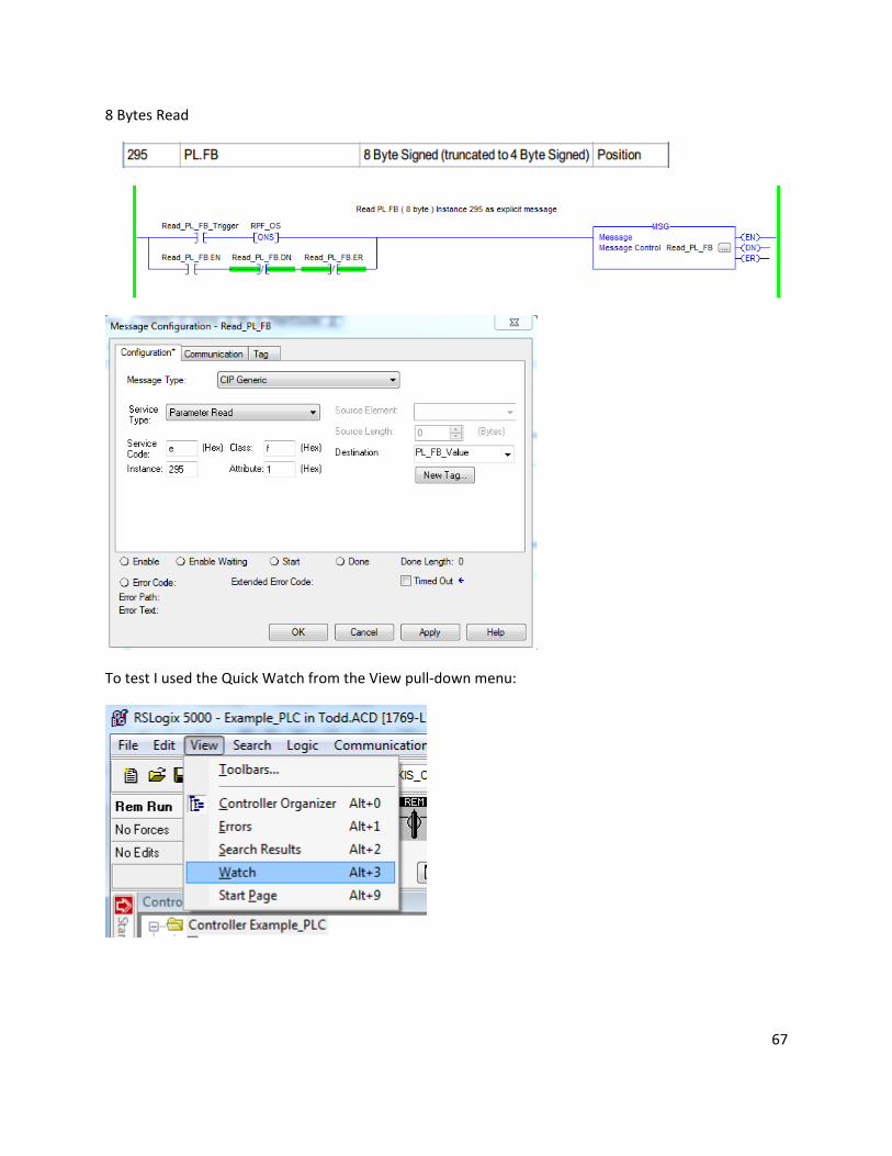
67
8 Bytes Read
To test I used the Quick Watch from the View pull-down menu:

68
Select “Quick Watch” from the Listbox”:
Begin selecting tags by clicking on the listbox arrow under the “Name” column:

69
The Quick Watch can be used to either set a value ( and then trigger the appropriate MSG block to
write ) or to read a value by triggering the appropriate MSG block and then checking the reported value
in the Quick Watch window.