al experiments concerning the hurtmann whistle
TRANSCRIPT

0
"ID EPARTM ENT O F E N G I N E E R I N G
Al experiments concerningthe hurtmann whistle
1. SAITNI A. POWELL
*COPY ..... 1;-;+-:+ . . ..
"-U NIVERSITY OF CALIF - 1IA, LOS ANGELES,
DDC --
DDC.IRA C
Report 64-42September 1964
EXPERIMENTS CONCERNING THE IIARTMANN HIIISTLE
T. J. D. Smith
Alan Powell
Reproduction in whole or in part is permitted forany purpose of the United Staten Government.
DIPARTHENT Of ENGINSERINGU1I4tRSITY OF CALIFORNIA
LOB ANOELKS

FOREWORD
The research described in this report, Ezperimenta Conceming the Hartmann
WAistle, by T. J. B. Smith and Alan Powell, was carried out under the technical direc-tion of Alan Powell and is part of the continuing program in Fluid Motion and Sound.
This study is conducted under the sponsorship of the Fluid Dynamics Branch,Department of the Navy, Office of Naval Research.
Submitted under Contract Number Nonr 233(62), Project Number 1313-009-01-01,Authority Number NH 062-229/11-19-62.
ii

ABSTRACT
The Hartmann whistle, in its most basic configuration, consists of a
flat-bottomed, cylindrical cavity which is axially aligned with a super-
sonic air jet of the same diameter. Discrete-frequency oscillations of
the enclosed air column are driven at large amplitudes when the cavity
is located within certain regions of the cellular structure of the jet. An
optical and acoustical study of the phenomenon is described, together
with that of the Hartmann 'pulsator'. In the latter form the whistle has
the small cavity replaced by a large Helmholtz-type resonator with the
same orifice diameter, resulting in a large-amplitude aeroacoustic os-
cillator with a periodic time of several orders of magnitude greater than
for the regular whistle. The underlying cause of the newly discovered bi-
stable condition of the normal 'shock-disc' located in the alrstream between
the nozzle and the cavity orifice is an important aspect which makes pos -
sible a (presently qualitative) theory of operation which accounts for the
principal features of the Hartmann whistle and its direct derivatives. Some
other aspects still requiring further elucidation and which are the subject
of continuing effort are mentioned. The Report includes a brief review of
the currently available literature pertaining to the phenomenon.

A SCHLIEREN STUDY OF THE HARTMANN WHISTLE t
INTRODUCTION
In certain divisions of engineering technology there is a growing needfor high-powered, discrete-frequency acoustic generators having outputswhich range from low audio-frequencies to extreme ultrasonic. The ap-
plications of such generators are many and varied and in general make useof the ability of high-intensity acoustic radiation to control combustion proc-esses, coagulate dusts and aerosols, emulsify liquid mixtures, cause fatiguefailures of certain structures and the like. To date most of the work of thisnature has been limited to small-scale experimentation, but proven applica-tions of airborne acoustic radiation to production engineering techniques arebecoming more and more widespread. The aerospace industries, for instance,make use of high-powered sonic generators for studies of fatigue failures of
airframes and space vehicles1 , for short-range signalling, and for combustioncontrol in solid propellant rocket motors 2 . There are many potential appli-cations of sonic energy to chemical engineering processes, such as the pre-cipitation and agglomeration of foams and aerosols, gas cleaning, powderdrying and the acceleration of certain chemical reactions 3 . In other branchesof manufacturing and production, sonic radiation has been shown to aid clean-ing and de-greasing operations and to increase tbh ..ombustion intensities ofoil- and gas-fired burners 4 . It is obviously desirable that the efficiencies ofsuch generators shall be as high as possible if the envisaged industrial proc-esses are to be economically viable, and for this reason, together with manyother significant advantages, high-powered whistles are being developed for
an increasing number of applications 5 ' 6 .
tCertain aspects were previously reported by Alan Pow<ll and T.J.B. Smith at the Sixty-FourthMeeting of the Acoustical Society of America (see J. Acoust. Soc. Am. 34, 1984 (A), 1963) andby T.J.B. Smith and Alan Powell at the Sixty-Seventh Meeting (J. Acoust. Soc. Am. 6 1018 (A),1964).

The types of acoustic generator used for the purposes listed abovemay be divided into three main categories: aerosonic, aero-mechanicaland electro-mechanical. The two latter forms utilize the flexure orperiodic displacement of a component part, either to interrupt a fluid
flow (as in the case of a rotating siren) or to generate pressure-waveradiation directly (as in the case of most magnetostrictive, piezoelectric
or electromagnetic transducers.) On the other hand, aerosonic generatorscontain no oscillating parts and depend on a combination of a fluid flow and
a fixed component of predetermined geometrical configuration to give rise
to acoustic radiation, as in the case of a simple whistle or organ pipe. Aero-sonic devices may be conveniently classified as 'static' devices, in contrast
to aero- and electro-mechanical transducers which embody moving com-
ponents, and hence will be referred to as 'dynamic' generators.
Static generators have many advantages over all other types--they aresimple to construct, require little maintenance or alignment and are o1'
inherently rugged construction since they may be made entirely from cor-rosion- and temperature-resistant matel'tals. They require only a supply
of compressed air or steam in the way of ancillary equipment, and, havingno electrical connections, may be used in explosive atmospheres--an im-
portant consideration where sonic energy is to be applied to combustion con-
trol or certain chemical processes.
Four main forms of static generator are recognized. These are the
Galton whistle, the Levavasseur whistle, the vortex whistle and the Hart-mann whistle. The first two are derivatives of the simple organ pipe and
depend for their operation on mechanisms related to subsonic and super-
sonic edge-tone phenomena. The mechanisms of the vortex and Hartmannwhistles are, as yet, not fully identified and the latter will form the basis
of this report. (The reader is referred to the work of Chanaud7 for the most
complete account to date of sound generation by vortex whistles.)
d
pp
2

The phenomenon which now bears his name was discovered by J. Hart-mann of Copenhagen in 1916 during the course of experimental investigationsof the axial stagnation pressure distribution along supersonic jet effluxes.He found that there were certain points in the jet stream where high-ampli-tude oscillations of the pressure-probe assembly were driven, a discoverythat initiated his investigations of the oscillations of other forms of closedcavities placed in the supersonic flow. Since then the phenomena has beenstudied by many researches (notably by Hartmann and his co-workers) butnone have yet been able to account for all aspects of the phenomena in asuitable theory for the initiation and maintenance of the oscillations.
Static Aerosonic Gu,,t.zrs
The tuned cavity excited by a low-velocity air jet has formed the basis ofmany musical instruments since prehistoric times, and in its simplest formis represented by the whistle shown in Fig. la. A pianar jet issuing from aslit orifice A is arranged to impinge on an edge B, giving rise to an edge tonefor a specific rangeof flows and-jet-to-edge distances. The tuned cavity Cgives rise to "forced"h edge-tonese. The acoustic output of such a device islow, but it may be slightly increased in the case of the Galton whistle9 .This is essentially a rotationally symmetrical device, consisting of the uppersection of Fig. la rotated about its longitudinal axis. Hence one obtains aquarter-wave resonant cavity excited by a coaxial annular edge-tone, againwith a relatively low acoustic efficiency, but capable of high frequencies andvery pure outputs (Fig. lb.)
Very much greater acoustic powers are obtainable from thesetwo whistles when the excitation jets exceed the critical pressure, since thesupersonic edge-tones excite violent oscillations of the enclosed air columns.Such oscillations are no longer classifiable as 'small perturbations' and dueto their non-linearity the emitted sound contains a high proportion of bothodd- and even-numbered harmonic components. Because of the absence ofdata pertaining to the supersonic edge-tone phenomena, the mechanism of thehigh-pressure Galton whistle is only partially understood, but research isproceeding on the elucidation of its action. A commercially successful high-pressure version of the simple whistle illustrated in Fig. la, known as the
3

IS
6 I
C ii
0
U
--I
4 1

4 4
0 F-a
(2'-44:0

Levavasaeur whistle, has been developed for which efficiencies ranging from5% to 15% are claimed, but again with only a partial understanding of itsoperation1 0 . (The Levavasseur whistle is the alternate rotationally sym-metrical derivative of Fig. Ia, consisting of the cross-section rotated aboutan external datum. The example shown in Fig. ic contains two toroidalcavities--a refinement that has been found by experiment to augment itsoutput.)
The Hartmann whistle differs from the foregoing examples in that it
has been shown to be largely independent of the classical edge-tone phenomenafor its operation. It consists, in its most basic form, of a cavity whose open
end is axially aligned with a high speed gas jet, or in some cases with anexternal supersonic air stream. When the jet velocity exceeds sonic speed
violent oscillations of the contained gases in the cavity are driven at or near
one of its resonant harmonic frequencies. Consequently intense discrete-
frequency acoustic radiation (in some cases over 150 watts 11 ) is emitted from
the open end at a relatively high aeroacoustic efficiency.
It has been found that weak oscillations of the air column can be excited
by a subsonic jet, but in such a case the combination of geometric and flow
parameters describing the necessary configuration for resonance is verycritical, implying perhaps that the mechanism of this type of oscillation isdue to some form of vortex generation, after the manner of the edgetone. In
the normal (supersonic) case these parameters are much less significant,
oscillations being driven over a wide range of pressures, jet-to-cavity dis-
tances and cavity dimensions. More information will be provided on this
aspect of the phenomenon in ensuing sections.
The cavity is usually in the form of a closed, cylindrical, flat-bottomed
resonator whose ratio of length to diameter may range from 0.25 to 50 or
more, the jet nozzle and cavity usually being of similar diameters (Fig. 2a).Very low-frequency oscillations (of the order of 0.5 c/s. or less) may be
obtained by using a large Helmholtz resonator as the cavity, sometimes re-
ferred to as the 'Hartmann pulsator '. Resonant cavities located in super-
sonic airstreams with their orifices directed towards the flow often emit
discrete-frequency sound of high intensity, especially if a 'de-stabilizing
6

9-4 4M >uF
Cl
rz4

doo.d .
8
f
Cq
42:
9

trip' is located upstream of the cavity, or if the orifice is oblique. These
oscillations are thought to have much in common with those of the Hartmannwhistle 1 2 . It is of interest to note that the phenomenon appears to be as-
sociated with ram-Jet instability (ram-jet 'buzz'), particularly where a dif-fuser spike located forward of the inlet orifice acts as a de-stabilizer 1 3 '1 7 .
From this it may be inferred that if any resonant cavity is included in asupersonic airframe there is a possibility that, when the orifice of such acavity is directed toward the direction of flight, undesirable oscillations mayoccur, together with an associated heating effect at its base (an aspect ofthe phenomenon that will be described in ensuing sections). It has also beenhypothesized that the deep pits found in certain meteorites arise as a result
of cavity resonance during the passage of the body through the atmosphere,the large-amplitude oscillations aiding the ejection of molten material from
the pits
The heating effect referred to in the foregoing paragraph is a furtherramification of the overall problem which has been the subject of muchresearch. It was mainly overlooked by early researchers who used short,
thick-walled resonant tubes surrounded by large heat sinks (the massive sup-ports and ciamps). Hartmann detected a temperature rise of only 70C at thebase of an oscillator having a length and diameter of 8 mm but later investi-gators using long, thin-walled tubes showed that the bases of such cavitieswere heated to temperatures much greater than the stagnation temperatureof the jet when oscillations of the enclosed gas were driven. Sprenger re-ported that cavities cut in wood or paraffin wax would become greatly enlargedby the heat generated and that tubes made of German silver distorted and
19melted
Researchers whose main interest was this particular phenomenon haveused the term 'resonance tube' to describe the apparatus used. Other namesgiven to it have included: 'gas jet siren', 'static siren', 'air-jet generator',
'jet-type vibrator', etc., but the authors have adopted the term used by Boucher(the 'Hartmann whistle') as being the least ambiguous, albeit not the mostself-descriptive terminology.
10

Previous Research
The first announcement of his discovery was made by Hartmann in 1919as a result of a series of experiments that he had been conducting to deter-
mine the nature of the stagnationpressure distribution along the axis of aspatially-periodic supersonic jetO. He found that violent oscillations oc-curred in the pitot tube whenever its orifice was located near points in theJet efflux where the stagnation pressure increased with distance from thejet nozzle. He identified the oscillations as being acoustic, the wavelengthof the sound emitted being some function of the longitudinal dimensions ofthe pitot tube assembly. This led him to try further experiments using alarge Helmholtz resonator in place of the pitot tube, a configuration whichhe referred to as a 'pulsator'. The system was found to oscillate with anextremely low frequency (of the order of a few cycles per minute) whichfacilitated optical observation of the external flow during the resonant cycleby means of a schlieren and shadograph system. It was noted that the cycleshowed two major flow conditions. For approximately half the periodic timejet efflux appeared to flow directly into the cavity, with the external detachedshock disc (the Reimann wave) situated close to, or within the pulsator orifice.Suddenly, the flow would reverse--there would be an impulsive movement ofthe normal shock in an upstream direction and the cavity would debouch. Asthe pressure in the cavity dropped, the location of the transverse shock moveddownstream until another sudden reversal of flow occurred and the jet wouldre-enter the cavity until the next debouchment, and so on.
Hartmann made further experiments with very small cylindrical cavities,some having a depth and diameter of only 0.5 mi. Spark-schlieren photo-graphs showed that the external flow variations occurring during resonanceof one of these cavities were essentially the same as occurred with the pul-sator. It was noted that the oscillations were driven when the cavity mouthwas located near the maxima in the total-pressure distribution curve for theair jet--no oscillations being driven near the minima. This observation gaverise to Hartmann's theory for the mechanism of the phenomena, which re-lates these 'intervals of instability' to his surveys of the stagnation pressurevariation along periodic jets. His modus operandi may be summarized with
11
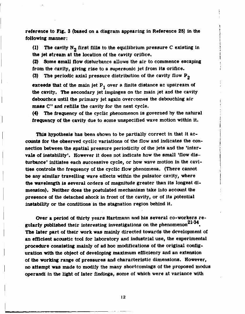
reference to Fig. 3 (based on a diagram appearing in Reference 25) in the
following manner:
(1) The cavity N2 first fills to the equilibrium pressure C existing inthe jet stream at the location of the cavity orifice.
(2) Some small flow disturbance allows the air to commence escapingfrom the cavity, giving rise to a supersonic jet from its orifice.
(3) The periodic axial pressure distribution of the cavity flow P2
exceeds that of the main jet P1 over a finite distance ac upstream of
the cavity. The secondary jet impinges on the main jet and the cavitydebouches until the primary jet again overcomes the debouching air
mass C" and refills the cavity for the next cycle.
(4) The frequency of the cyclic phenomenon is governed by the natural
frequency of the cavity due to some unspecified wave motion within it.
This hypothesis has been shown to be partially correct in that it ac-
counts for the observed cyclic variations of the flow and indicates the con-
nection between the spatial pressure periodicity of the jets and the 'inter-
vals of instability'. However it does not indicate how the small 'flow dis..
turbance' initiates each successive cycle, or how wave motion in the cavi-
ties controls the frequency of the cyclic flow phenomena. (There cannot
be any similar travelling wave effects within the pulsator cavity, where
the wavelength is several orders of magnitude greater than its longest di-
mension). Neither does the postulated mechanism take iznto account the
presence of the detached shock in front of the cavity, or of its potential
instability or the conditions in the stagnation region behind it.
Over a period of thirty years Hartmann and his several co-workers re-2 1-34gularly published their interesting investigations on the phenomenon
The later part of their work was mainly directed towards the development of
an efficient acoustic tool for laboratory and industrial use, the experimental
procedure consisting mainly of ad hoc modifications of the original config-
uration with the object of developing maximum efficiency and an extension
of the working range of pressures and characteristic dimensions. However,
no attempt was made to modify the many shortcomings of the proposed modus
operandi in the light of later findings, some of which were at variance with
12
I I0 II
0 I II II II II I
SpI ICI pe
I I ¢
I -S/ I
hi - 0. S I
IN II I
I 'I
DIAGRAM TO ILLUSTRATE HARTMANN' S POSTULATED MECHANISM
FIGURE 3
13

the initial suppositions, and several other errors of observation were per-petuated which tended to obscure information that would have led to a
better understanding of the mechanism.
Nonetheless, Hsrtmann laid the groundwork for all subsequent investi-
gations by his painstaking examinations of so many features of the whistleand he was able to indicate the optimum dimensions, working pressures and
assembly techniques necessary to obtain the maximum aeroacoustic efficiency.Tests were performed on a wide range of variations of the basic assembly.
Among the modifications tested were the use of reflecting surfaces around thenossles and cavities for intensification of the output; jets and cavities ofroctar4gua or annular section; various nose profiles of the cavities; variousratios of the jet diameters, cavity diameters, resonator lengths and jet-to-
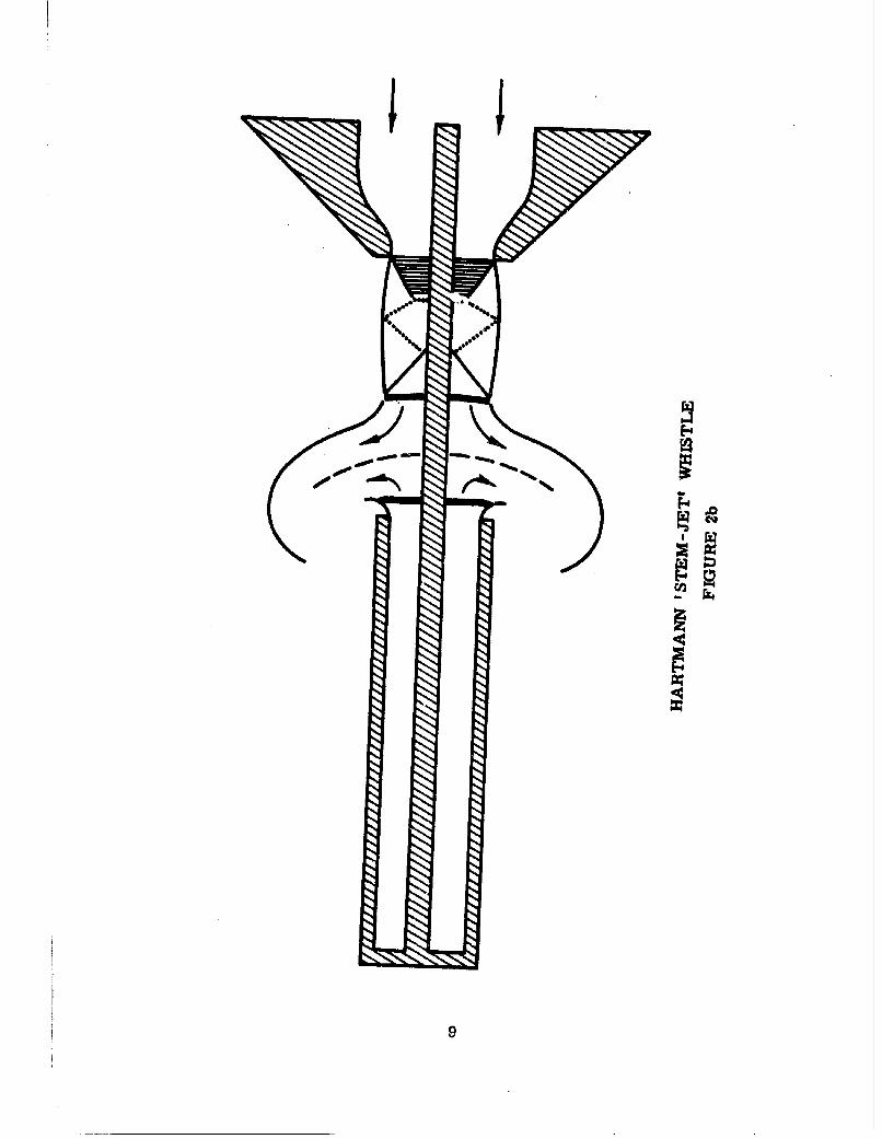
orifice separations; synchronization of two whistles, and many other suchassemblies. The most successful configuration appeared in the form ofthe 'stem-Jet' (Fig. 2b) where an axial rod runs through the jet stream fromthe cavity to the nozzle. (This form was discovered independently bySavory and announced at the same time as Hartmann's publication , butthe former was precluded from making any investigations of the phenomenondue to the extremely small dimensions of his apparatus.) The stem-jet variesin so many ways from the standard Hartmann whistle that several reviews havetended to treat it as a separate class of aerosonic generator. Its output isalmost completely independent of the nozzle-to-cavity spacing, neither theamplitude nor the frequency of the whistle changing over wide variations inspacing, and it is completely insensitive to 'intervals of instability' in thejet etflux. Perhaps the most outstanding variation from the Hartmann whistleis the fact that oscillations of the cavity occur for all flows--from extremehigh-pressure jets down to low subsonic velocities, and the arrangementmakes it possible to keep certain levels of intensity constant while reducing
the air consumption by as much as 50%, thus giving an efficiency which istwice that of the best Hartmann whistle. No explanation has yet been offeredfor this variation from the observed properties of the basic configuration,
although it is obvious that the stem acts as a destabilizing device.
14

Using a Rayleigh disc indicator for measurements of the polar radiation
distribution and acoustic power output, Hartmann found that the maximumobtainable aeroacoustic efficiency of the basic form of the whistle was about
6% when the diameter of the cavity was equal to its length. This value de-creased with increase in excess pressure past a maximum of 1.5 atmospheresand also optimized at certain nozzle-to-cavity separations.
The Hartmann whistle has attracted the attention of many other experi-menters. The main field of interest was the development of a practicalaerosonic generator, but certain investigators concerned themselves morewith the purely physical problems arising out of the phenomenon--in par-ticular the apparent thermal imbalance, the travelling shock waves in thecavities and the problem of indentifying its mechanism of operation.
Ehret and Hahnernan 35 were the first to realize the potentialities of thesystem and developed a form of the whistle which was used for the ultra-sonic testing of alloys. The cavity took the form of a small T-sectionedHelmholtz resonator, the narrow neck directed towards the jet and a membraneforming the back wall from which the oscillations were mechanically coupledto the specimen. This configuration has also been investigated by Kling and
Crabol3 6 who reported outputs reaching 220 kc/s. Like Ehret and Hahnemann,they also surrounded the jet by an annular reflector which increased the out-put and gave rise to oscillations of the system with subsonic jets--possiblyas a result of the reflector aiding acoustic feedback of vortical instabilitiesfrom the cavity orifice to the jet in a similar manner to the mechanism ofedge-tone production.
Savory37 constructed a variety of forms of the whistle and made studiesof the effect of introducing de-stabilizing devices into the jet stream aheadof the cavity. These additions included axial rods (the 'stem-jet generator'),annular rings and 'regenerator pads' (small reflectors close to the jet bound-ary). Each showed a tendency, under certain conditions, to augment the acous-tic output and to improve the over-all efficiency.
15
Palmse made stroboscopic shadowgraph studies of the oscillatoryextervial flow which enabled the cycle to be studied in greater detail, andexperimented with disc extensions around the jet nozzle and cavity orificewith the object of increasing the acoustic output. He recommended that,f9r maximum efficiency, the diameter of the cavity should be equal to thewidest diameter attained by the cell structure of the jet efflux. Monson andBinder 3 e also found that maximum Intensities were obtained when the ratioof the cavity diameter to jet diameter was equal to 1.27, values in excess of
this giving progressively lower outputs until a value is reached (at approx-imately 1.60) where the cavity fails to resonate.
Brun and Boucher 1 1' 4 0'4 1 directed their research activities towardthe development of a high-powered generator for industrial applications.Their 'Multiwhistle' took the form of a group of Hartmann whistles mountedin the throat of a exponential horn and backed by an ancillary resonantcavity. Tests of various ratios of cavity diameter to jet diameter supportedthe findings of Palms, and Monson and Binder--that when the value of theratio was in the region of 1.33 it was possible to virtually double the efficiencyof the generator, and under optimum operating conditions, efficiencies rangingbetween 10% and 20' were claimed for the Multlwhistle. Similar claims weremade by Kirkin 42j43 for a composite whistle of like configuration. Otherexperimenters who Investigated the general features of Hartmann whistlesinclude White4, Bugard4 5 and le Landals4 6 . The work of le Landals is ofinterest as it represents the first commercial development of the stem-jetwhistle as an engineering product and contains a useful review of the pro-perties of this generator. Nomoto4 7 mapped the 'regions of instability' ofa simple Hartmann whistle for all pressure ratios up to 4.0 and by means ofcontours of equal loudness was able to display the optimum nozzle-to-cavityspacings for any given working pressure.
Among the few theoretical examinations of the acoustical aspects of thephenomenon is that undertaken by Gravitt 4 8, who attempted to provide a unified
theory for the frequency response of a given resonator. However, he was onlyable to obtain partial agreement with experimental results due to the adoptionof small perturbation theory as the basis of his analysis, with the consequent
16

omission of significant second-order terms, including those accounting forviscous action and thermal transfer.
A non-acoustic study of the Hartmann whistle was conducted by
Thompson49 assisted by simultaneous studies of flow visualization for thesystem by Fai 50 and Hartenbaum51. The object of this work was to catalog
the broad features of the fluid dynamics of the phenomenon in order to com-
pile sufficient data for further studies of the temperature rise in the cavities.
Experiments conducted with both fully-expanded and periodic Jets showed thatthe oscillations of the cavity were essentially similar in each case, although
minor distinguishing differences were noted for the respective flow phenomena.A large amount of data was compiled by these authors, particularly with respectto movements of the normal shocks within and outside the cavities; however,no tenable theory for the initiation and maintenance of the oscillations was ad-
vanced.
A significant theoretical and experimental examination of the Hartmannwhistle was recently reported by MCrch52. Commencing with a detailed exam-ination of the flow within a periodic jet efflux, Mirch proceeded to investigate
the oscillations of the normal shock in front of cavities and blunt bodies, usingstroboscopic schlieren techniques. The majority of the experimental work was
performed on 'resonators without bore'--i.e., solid blunt bodies having the samesilhouette as the resonant cavities. The advantages claimed for this technique
were that the stagnation flow was simplified and the amplitude of the oscilla-tions was reduced, thus forming the basis for comparison between small per-
turbation theory and his experimental data. M~rch also detected weak oscilla -tions of the normal shock at positions where it had hitherto been considered tobe stable. This condition he termed 'weak resonance', as opposed to the normal
'strong resonance'. The instability model proposed by this author, based on
small perturbation theory, envisages the shock making small oscillations aboutits position of equilibrium. In this way pressure and velocity perturbations areproduced in the region behind the shock and move downstream as plane sound
waves; tiese waves are then reflected at the normal face of the body and moveupstream towards the shock through the subsonic stagnation flow. Ii the per-turbation, on arriving at the shock, is in phase with its oscillation resonance
17

will occur; If not* the movement will be uninfluenced or damped. Thus theshock-to-re.-onator p I a n e distance will be of major importance indefining the conditions uader which resonance occurs. The theory and
computations developed from this model are apparently only applicableto weak oscillations near a plane baffle. Substantial modifications, atleast, would be necessary to account for the severely non-linear oscil-
lations of a typical cavity--while it can hardly be applied to the case of a
Helmholtz resonator where the periodic time is very long.
Thermal Effects in Hartmann Whistle Cavities
The heating effect at the base of a Hartmann whistle cavity has received19Attention from both experimental and theoretical analysts. Sprenger drew
attention to the fact that the temperatures generated within the tubes were verymuch greater than the free stream stagnation temperature, Using a tube of
10.0 cm length and 0.3 cm diameter which was excited by a spatially periodicjet at a reservoir pressure of five atmospheres, he found that the wall temper-ature at the closed end reached over 450°C, but erroneously attempted tocorrelate the mechanism of the phenomenon with that of the Ranque-Hilsh
vortex tube. Sprenger noted from observations of a hydraulic analog of thesystem that a quantity of residual fluid was retained by the tube at its closedend which was subjected to repeated high-amplitude pressure changes during-the oscillatory cycle, but did not infer from the hydraulic model that any shock-waves were present within the tube. However, this was suggested to him by
osciliograms obtained from a pressure transducer attached to the resonatorend-wall, when it was noted that extremely steep-fronted pressure wave-formswere recorded during each compression of the cavity fluid.
Sibulkin and Vrebalovich 5 3 studied the heating effect using a 10 inch longcavity located within a supersonic wind tunnel and fitted with a destabili'singtrip in the form of a. ring-airfoil forward of its orifice, with which they detectedtemperature rises in excess of 1500C. Like Sprenger, they also observed a
similar effect occurring at high-speed subsonic flows, provided the trip waspresent. It was inferred that the dissipative mechanism whereby thermal energywas released was in some way connected with shock wave motions within thecavity. Hartmann had tentatively suggested the existence of such a travelling
18

wave and it had already been shown that weak periodic shock waves appearunder certain conditions when a closed column of gas is forced to oscillate
by a sinusoidally-vibratihg piston at one end of the column 5 4 '5 5. Visualproof of the existence of the internal shock in the Hartmann whistle phenom-enon was first provided by Hall and Berry56 who obtained a series of timedspark-schlie'-i photographs of a shock wave moving along a 2 inch glass-
sided cavity excited by a periodic jet. (This data was construed by WilSonand Resler5758 as indicating that steepening pressure waves, rather thannon-isentropic shock wave movements, caused the thermal build-up. Atheory advanced by them for the mechanism of the heat generation provedto be inconclusive due to the omission of many factors governing the be-havior of the gases in the resonator together with an incomplete under-
standing of the features of the resonant cycle.)
Shapiro 59 ' 6 0 and Howick and Hughes 6 1 made limited experimental andtiteoretical analyses of the thermal energy balance, and, starting from the
premise that the heat gain arises as a result of viscous dissipation in theshock wave, attempted to determine the maximum obtainable temperaturefor a given resonant cavity from estimates of the heat gain from the shock,(the product of the frequency and the total amount of energy dissipated by theshock during one cycle) and the heat loss from the tube walls. The heat lostto the fluid debouched at the end of each cycle was overlooked, but Howickand Hughes, by insuiating the walls of a 14 inch long tube, were able to raisethe end wall temperature from 4500 C to 6500 C, showing that the heat loss byconduction to the surrounding air blast was a major cause of the depressionof the maximum temperature. It was also surmised by Shapiro that an ad-ditional source of thermal energy might arise from the oscillating boundarylayers on the tube walls.
Vrebalovich 12 later made extensive tests of the thermal dissipationmechanism, his experimental apparatus being restricted to the case of aresonant cavity located in a supersonic stream. He found that whereas certainblunt-nosed tube profiles required the addition of de-stabilizing trips locatedupstream of the orifice to initiate and maintain the resonant condition, sharp-lipped tubes would oscillate in the absence of such ancillary equipment. Thisled him to postulate that the oscillatory cycle was inititted by some flow dis-
turbance (an edge tone at the lip or de-stabilizer, for instance) which caused
19 

the stagnation point of the stagnation streamline to move in an axial di-rection and thus change the size of the flow separation region which wasobserved to originate near the lip of the tube. Since this separation regionaffects the shock shape and the flow field in front of the orifice, Vrebalo-vich postulated the existence of a feed-back mechanism which might bethe cause of a periodic flow disturbance that would maintain the oscilla-
tions of the air column. Any pressure disturbance propagated to the baseof the tube would be reflected back to the mouth to further upset the stag-nation point location and in this way the cavity length would control theresonant frequency. Vrebalovich successfully correlated the many uncon-nected observations of previous workers to account for the heat gain bythe cavity. The thermal build-up was shown, both experimentally and the-oretically, to arise from the repeated transit of the tube by a shock wavefrom which the 'residual fluid' (the proportion of the contained air remain-
ing within the tube for more than one cycle) gained heat by the viscous dis-sipation process. Consequently the residual fluid will attain a maximumtemperature which is limited by heat losses through the tube walls and themixing process with the non-residual fluid in the cavity. (Tests showedthat approximately 90% or more of the initially captured gas is retained inthe tube for the following cycle).
From the foregoing digest of the currently available literature relating-to the Hartmann whistle and its properties and applications, it is evidentthat the present state of our understanding of this complicated phenomenonis still incomplete. A brief experimental survey of the feacures of a typicalwhistle serves to raise many queries concerning its properties that, to date,have remained unanswered. Typical of the problems yet to be solved is thaquestion of the mechanism whereby the oscillations are initiated and main-tained. Why are the 'intervals of instability' separated by regions in whichthe flow is stable? Why dothe oscillations start and cease instantaneously,rather than growing to a maximum and falling off according to some exponen-tial law? How does a de-stabilizing trip aid the generation of oscillations?Is there more than one mechanism whereby oscillations are driven, and if so,are they independent of each other, or are several types of instability phe-nomena simultaneously in evidence?
20

These and other questions will be examined in the remainder of thisreport, based on experimental investigations of the Hartmann whistle at
the Aerosonics Laboratory of the University of California, conducted be-tween August 1961 and August 1964.
EXPERIMENTAL EQUIPMENT
The experimental assembly used for the following investigations of theHartmann whistle in shown in Fig. 4. A 1.25 in. diameter horizontal air-
supply manifold was mounted so that jet nozzles of various types could bescrewed into its end, and resonators, clamped to a cross-slide, moved along
the jet axis relative to the stationary nozzles. The equipment was constructedin this manner so that a wide combination of nozzles, cavities, pressure-probes, baffles, etc., could be used in conjunction with it, without the need todissemble or otherwise modify the basic configuration.
The air-supply manifold and the cavities were separated by a distanceof 12 ins. from the base-plate in order that the schlieren field should remain
unobstructed and so that the base (which was kept small in area) would notreflect acoustic energy back to the flow field which could assist in establishingacoustic feed-back loops for the instability phenomena being investigated. Thecavity clamp post was made as slender as possible, while maintaining the re-
quired mechanical strength, in order that there should be no undue disturbanceof the air flow around it, and was equipped with facilities for adjusting the align-
ment of the cavity along the jet axis in both the vertical and horizontal planes.The apparatus was connected to the laboratory compressed air supply througha filter and control valve, the air supply being sufficient to maintain an excesspressure of at least 75 lb/in2 on a 5/16 in. nozzle. A set of calibrated Bourdon
pressure gauges, coupled to a pressure tapping in the manifold just upstream ofthe convergent nozzles, was used to record the jet excess pressures and thenozzle-to-cavity separations were determined from a vernier scale on the cross-
slide.
Previous research by Hartmann, et al., has shown that the aeroacoustic ef-ficiency of a Hartmann whistle maximizes when the ratio of the cavity and jet
diameters approaches a value of 1.3; and when the cavity length is equal to itsdiameter. However, since the following investigations were directed towards a
21
>
22

better understanding of the mechanism of the Hartmann whistle and its
properties, the efficiency of the system was of secondary importance andit was decided to keep all cavity and jet diameters equal and to provide
for a wide variation in the resonant frequencies of the cavities.
Two characteristic diameters were employed, these being 1/2 in. and5/16 in. The former, due to its relatively larger scale, was mainly usedfor optical visualization of the flow variations but was limited by its maximum
pressure ratio (with the available air supply) of only 3:1. The smaller dia-
meter system, having a maximum pressure ratio in excess of 6:1, was there-fore used for surveys of the acoustical characteristics of the whistle cover-
ing wide pressure ranges.
A set of cylindrical cavities ranging in length from 1/2 in. to 1.6 ins.(the resonant frequencies ranging from approximately 6 kc/s down to 190c/s) was provided for each jet nozzle. All cavities were constructed with
a lip chamfer ranging from 300 to 450 to the axis which ensured that the
sonic shoulder of the flow lay at the lip of the tube and not on its outer sur-face. (Morch5 2 had found that the critical chamfer angle at which the sonicpoint moves from the cavity lip to the intersection of the chamfer cone and
outer cylinder is in the region of 600.) All cavity pieces and nozzles weremade of aluminum and the entire experimental assembly was located in an
enclosure equipped with acoustically-absorbant walls which reduced the
external sound levels to an acceptable value.
Acoustic measurements of the performance of the whistle were mainlyrestricted to determinations of the emitted frequencies and the spectralcontent of the sound. (As noted already, the acoustic power output, thedirectivity and efficiency were of secondary interest in these tests.) A
Brtfel and Kjaer Type 4133 standard capacitor microphone, directed towardthe cavity orifice, was mounted on a simple linear traverse which made an
angle of 135 0 with the downstream direction of the whistle axis. The motionof the carriage was remotely controlled by a synchronous motor drive sothat the microphone location could be continuously varied through a distance
of six feet up to cavity lip. Frequency and spectral analyses were obtainedfrom a BrUel and Kjaer Type 2107 frequency analyzer and Type 2305 level
recorder, with frequency read-out on a Hewlett-Packard AC-4 decade counter.
23

I
Filtered outputs from the analyzing equipment also served to trigger thespark- and strobe-illumination for the optical flow-visualization equip-ment, as indicated in Fig. 5.
A schlleren-shadowgraph system was assembled for optical studiesof the periodic flow variations, using 6 in. diameter parabolic mirrorsof 84 ins. focal length and vertical orientation of the source slit and knife-
e*e. In this way schlieren-shadowgraphs were photographed or projectedonto the viewing screen in the normal manner, or direct shadowgraphs ob-tained by placing a photographic film in the collimated beam at a pointbehind the apparatus as shown in Fig. 6. Three types of light-source wereused. A high-intensity constant source provided by a 500-watt incandescent.amp was used for general observation of the flow-field and for the purposesof aligning the optical equipment. For high-speed photography of the flowsthe light-source consisted of an 8-mm. spark discharged between magnesium-electrodes, having an estimated duration of less than one microsecond andextremely high light intensity. The spark could be triggered at a predeter-vne wtant during the resonant cycle by a suitable electrical pulse
derived either from the pressure- or sound-analyzing equipment, or couldbe fired at arbitrary time by a switch circuit. Phased photographs ofperiod ýýf ow variations were obtained by triggering the spark from the
microphone output. A filtered waveform from the analyzer output was con-nected to the trigger circuit through a variable-gain amplifier. By increas-ing the amplifier output until the peak amplitude of the waveform just at-tained the threshold voltage necessary to trigger the spark, the dischargecould be arranged to occur at the same (peak) point in the output waveform,and by moving the microphone through a distance equal to one wavelengthof the emitted sound, a series of accurately phased schlieren frames of anyregularly periodic sound-emitting flow phenomenon was obtained.
Vismul observations of Hartmann whistle oscillations were aided byschlieren-shadowgraph studies using stroboscopic illumination. Replac-ing the spark electrodes by the xenon flash lamp of a General Radio Type1531-A 'Strobotac', the flashing rate of which was triggered by a waveformderived from the acoustical output, made it possible to observe in detail anyselected phase of the resonant cycle; or the entire cycle could be studied in*slaw motion' by steady movement of the microphone along its traverse.
24
mu
ac
_Jku w r3WO)WO A
ty goWe Lh
00
252
Ai
a..
Ip
II-6 I I;-

Several types of films were used for spark-schlieren photography
and, because of the short duration of the exposure time, the normal sensi-tivity rating of the film emulsion was found to be of secondary importance,due to the 'reciprocity-law failure' of the emulsions. Consequently, filmswith sensitivity ratings ranging from 25 ASA to 700 ASA were used with
equal success, and were developed in Kodak DK 50 or Baumann Diafine.Polaroid 'Pola Pan' materials were used where 'single-shot'data wererequired.
GENERAL SURVEY OF PROPERTIES OF THE HARTMANN WHISTLE
Although several investigators have undertaken surveys of the acousticalproperties of the Hartmann whistle, it was found that the available data weresurprisingly limited in scope, particularly for resonators having length-to-diameter ratios in excess of 2.0. (Hartmann and most other authors haddirected their researches toward the development of ultrasonic generators
and hence had used cavities and jets of very small scale). When the cavitydiameter is equal to, or exceeds its length--as is generally the case when
used for the generation of very high frequencies--the connection betweenthe wavelength of the emitted sound and the small-amplitude 'resonant'cavity length becomes uncertain, due to the magnitude of the correctionfactors to be incorporated in the latter. Only a limited amount of informa-tion was available relating to the frequency responses of long cavities orto the exact relationship between the jet structure and the 'intervals ofinstability', and for this reason a series of simultaneous schlieren-shadow-graph and acoustic parametric surveys were made to determine the effect
of variations in cavity length, jet pressure, nozzle-to-cavity separation,
etc., on the output of a Hartmann whistle.
The External Flow
To gain information on the periodic flow variations near the orifice of
a oscillating cavity, phased shadowgraphs were taken at selected intervalsduring the resonance cycle, using the spark-triggering technique describedin the previous section. For the purposes of this test a 2 in. long cavityof 0.5 in. diameter was located 0.58 in. from a 0.5 in. nozzle in one of the
27
unstable zones, where it oscillated at its first harmonic frequency of
1,413 c/s when excited by a periodic jet of 35 lbs/in2 excess pressure.
Fig. 7 illustr;,tes the flow variations recorded at regular intervalsthroughout the cycle. The frames, arranged in chronological order,were taken at approximately 37 microsecond intervals by half-inchmovements of the microphone traverse. The computed elapsed time,in microseconds, from the emission of the pressure wave is shown on
each frame and may be considered accurate to within t 5 microsecondsof the value stated. The main features of this study can be summarizedas follows:
1. Mass-flow variations. The cavity charges with fluid from the jetfor approximately half of the cycle and then debouches, there being evi-dence of powerful vorticity developing during the discharge.
2. Detached shock instability. The normal shock-disc separating thesupersonic flow from the separation region oscillates with large ampli-tude in an axial direction, with periodic distortion of its normal (stable)shape. The motion of the shock is plotted in Fig. 8.
3. Acoustic output. The large mass-flow variations at the cavityorifice gives rise to high-intensity acoustic radiation which is charac-terized by a periodic waveform having a fast rise-time and of similar
shape to the graph of the axial movements of the shock. In consequencethe emitted sound is rich in odd- and even-numbered harmonic frequencycomponents. The steepfronted out-going pressure wave is visible in thefirst three frames of Fig. 7.
An estimate of the fluctuating pressure at the closed end of the cavitywas obtained by replacing the end cap by one containing a small orifice(Fig. 9). A periodic jet issued from this perforation during part of theresonant cycle, and the dimensions of its cell structure gave an indica-tion of the pressure within the tube at a given time. Typical orificeflows are shown for various phases of the cycle in Fig. 9. From meas-urement of the lengths of the first cell of the emergent jet, values of the
28

-4
* i
SERIES OF
PHASED
SPARK-SCHLIEREN
SHADOWGRAPHS
OF
0.5 IN.
HARTMANN
WHISTLE
RESONATING
AT ITS
FIRST HARMONIC
FREQUENCY
02
L .0iP=S bi .5 n = 141 /
FIGURE
7
29
0.40 s0.INL a 2.0 IN.
I " 0.561N.
10.30
at
CENTIER
o.0.0 i
0 l00 200 300 400 G00 Go00 700 60
TIME, (MiCMECONDS)
OSCILLATION OF DETACHED SHOCK DISC OFRESONATING HARTMANN WHISTLE CAVITY
FIGURE 8
30

-i
j
V -- A
SPARK-SCHLIEREN SHADOWGRAPHS OF THE VARIABLE-PRESSUREPERIODIC JET EMERGING FROM THE END-WALL PERFORATION
OF AN OSCILLATING 0.5 IN. HARTMANN WHISTLE CAVITY2
L = 2.0 in, P = 35 lb/in , h = 0.58 in, f = 1413 c/s
FIGURE 9
31

generating pressure were derived from the empirical formula developedby Hartmann: 51 /Po 1.96
-1 0O-ID = 0.30 + 0.98
where 61 it the length of the first cell, D is the nozzle diameter and P.the absolute pressure of the jet in kg/cm2 , for cell aspect ratios greaterthan jnty.
The pressure variation at the closed end of the cavity is displayedin Fig. 10. These values are only approximate since no correction wasincorporated in the above expression to account for the pressure reductiondue to the fluid loss from the rear of the cavity, but comparison with dataobtained by other authors12049'59 using different measuring techniquesshows a close agreement, both with the values of pressure plotted and thesh"e of the curve.
The Internal Flow
The foregoing observations of fluctuating pressure at the cavity base,together with other studies of the phenomenon by various authors (reportedin the Introduction) tended to indicate a possible connection between thetravelling shock within the tube and the mechanism of the whistle.
To establish the relationship between variations In the internal andexternal flows, square-section transparent-sided cavities were constructedin which the cyclic phenomena at the orifices and along the entire lengthof the tubes were simultaneously in evidence.* These cavities consisted of3/8 in. wide channels cut in 3/8 in. aluminum plates which were sandwichedbetween two optically-flat glass windows, the assemblies being made gas-tight by rubber-strip seals. Thus the entire length of the tubes up to their
'Ot was found that a fully two-dimensionad system, enclosing the nozzle, jet flow and cavitybetween two glass plates, would not oscillate under any combination of circumstances in theabsence of an added tripping mechanism, and even placing a flat surface close to the jetboundary of the normal axially symmetric configuration was sufficient to damp. all oscilla-tions.
32

d
. W. o -Vd 0 1 I I,
0 I00 0
gNI/91 *•I6VO A.IIAVO IVY •l$3WU ld $$81X31
33
-- --N -- - -- - -

exists could be viewed in the schlieren field. The cavities so formed couldbe excited by either the 5/16 in. or the 3/8 in. jet--the latter being chosenbecause of its proportionately larger scale and clarity of the external flowfeatures.
The previously noted variations in the separation flow and the jetemerging from the rear perforation were connected to the movement ofthe internal shock with the aid of a 2-Inch transparent-sided cavity whichhad a small orifice drilled out in its thin end-wall. The events of onecycle during resonance of this cavity are displayed in Fig. 11, where thegeometrical and flow parameters remain the same as for Figs. 7 and 9.(The change in the cross-sectional shape of the cavity orifice resultedIn a small shift of the resonant frequency from 1,413 to 1,430 c/s.) Themotion of the Internal shock is easily discernable and its displacement asa function of the periodic time Is shown in Fig. 12, where the movementof the detached shock disc is also displayed. The velocity of the internalshock relative to the tube is more or less constant at about 87.5% of sonicspeed--a feature that has been borne out by similar tests on longer channels.
The main features of the resonance of a rectilinear cavity excited bya periodic jet may be assembled from the foregoing three optical surveys,
illustrated in Figs. 7, 9 and 11. The cycle may be considered to commenceat the time when the radiated pressure wave originates at the cavity orifice,that is to say, as the debouchtment commences. At this instant the pressure
at the cavity base Is near a maximum but falls rapidly as fluid is expelled.The external detached shock which separates the supersonic jet flow fromthe stagnation flow at the orifice moves upstream with high velocity asdebouchment commences an the powerful radiated pressure wave is initi-ated. The shockwave remains at this outer position as the cavity debouchesuntil, as the emergent mass-flow rate falls off, it eventually moves back toits original location. At approximately the half-periodic time the debouche-ment ceases and fluid commences to flow into the cavity, accompanied by atravelling shock wave which transits - the tube at near-sonic velocity. Arrivalof the shock at the end wall causes a vortex ring to be emitted from the per-foration In it, with the development of a periodic jet due to the high pressureattained at the cavity base. (Note that vortex ring is also formed within the
34
4W"
Si~
PHASED SPARK-SCHLIEREN SHADOWGRAPHS OF THE OSCILLATION OFA 0. 375 IN. TRANSPARENT-WALLED HARTMANN WHISTLE CAVITY
D 0.5 in, L = 2.0 in, P = 35 lb/in , h = 0.58 in, f = 1430 c/s
FIGURE 11
35

oo
@1~~~~ 00* o o d
VNI) AIIAVO MIN~.IM (WI 3NVIIIONOlivool NmoH3 osia - NOMS 01 AIIAVO
36

cavity at the same instant.) The shock, on reflection from the end of thecavity, arrives at the orifice to complete the cycle and the cavity again
debouches. Presumably an expansion fan transits to tube during debouche-
ment, initiated by reflection of the internal shock at the open end as in-
dicated in Fig. 12.
Frequency Response of the Hartmann Whistle
Variations of the acoustic output of the whistle with changes in jetpressure, cavity location, etc., were noted by Hartmann during hisinitial studies of the phenomenon. He drew attention to the connectionsbetween the geometry of the efflux cell-structure and the cavity locationswhere the flow changed from the stable (non-resonant) to the unstable(resonant) condition, and named these zones the 'intervals of instability'.He also determined the wavelengths of the emitted sound over a limitedrange of distances and cavity dimensions (having lengths more-or-lessequal to their diameters in the range 2 - 10 mm) as the jet-to-cavity se-paration was varied, but major deviations from the natural resonantfrequencies occurred because of the extreme non-linearity of the oscil-lations. As a result it was erroneously assumed that throughout the firstand subsequent instable zones the wavelength varied as a linear functionof the cavity location, the frequency falling as the spacing increased. Tests
on longer cavities would have shown this to be incorrect but, apart fromthese surveys, no other detailed investigation of the variations of the soundof a Hartmann whistle has been reported.
In order to extend the range of the studies referred to above, thefollowing measurements were made of the frequency response, which
relate the acoustic output of a typical cavity to the jet pressure (and henceto the jet structure) over the first three jet cells. It was found that allcavities having lengths in excess of five diameters behave in essentiallythe same way--high harmonic frequencies being driven at the upstream
end of each instable zone and the first harmonic over the downstreamand longer part. Minor variations of their responses are attributable todifferences in the ratios of jet to cavity diameters, the cavity lengths andcross-sectional shapes, the shape of the cavity lips or, in general, tovariations in the Q-factors of the resonators.
37

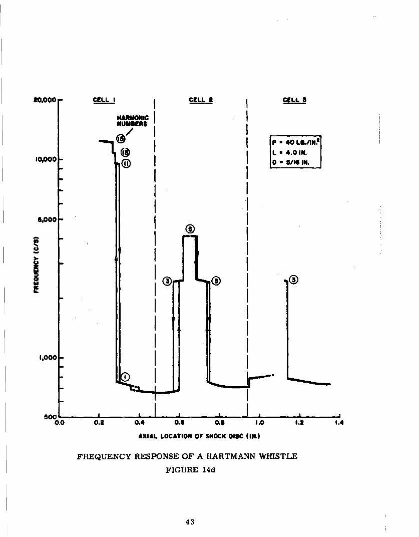
A survey of the limits of the unstable zones, similar to work by No-moto4'7 is displayed in Fig. 13, where the locations at which a 4-inch
cavity resonated when excited by a 0/16 in. jet are plotted as a functionof the Jet pressure. It will be noted that, for jet pressures in excess of43 lb/in2 , the cavity resonated at all positions downstream of the initialstable zone. For lower pressures, down to approximately 25 lb/In 2,
the unstable zones were centered on, or crossed the cell boundaries, butbelow this jet pressure the zones lay entirely within the cell limits.Further investigations showed that the apparent shift of the unstable zonesrelative to the jet geometry was due to the fact that the significant charac-teristic dimension defining their Iccation was not so much the nozzle-to-cavity spacing but rather the position of the detached shock along the jetefflux. It was noted that, as the cavity (and hence its associated shock-disc) was slowly moved away from the nozzle, the shock became unstableand commenced to oscillate near the apex of each expansion cone in thejet efflux and ceased oscillating when it approached the end of each cell.Therefore, the frequency responses of the 4-inch cavity in the unstablezones are plotted in Figs. 14a to 14f as a function of the detached shocklocation, for jet pressures ranging from 20 to 50 lb/in2 . The differencebetween the nozzle-to-cavity spacing and that from the nozzle to the centreof the shock disc (being the width of the stagnation flow, or 'stand-off dis-tance') ws determined from observations of a stable detached shock infront of a blunt body of the same external profile as that of the cavity body.The stand-off distance were found to remain constant as the blunt body wasmoved along the periodic Jets, but minor variations occurred as the Jet pres-sure was increased, the largest separation distances being recorded for thelowest jet pressures.
Examination of Figs. 14a to 14f indicates that, for all jet pressuresless than approximately 40 lb/in2, the jet effluxes have a regular spatialperiodicity, and basically the same cavity frequency response is repeated
over each successive cell-length. Jet pressures in the range from 40 to43 lb/in2 represents a transition condition (Fig. 14d) and over 43 lb/in2
the spatial periodicity breaks down and the first harmonic frequency ofthe cavity is driven at all points along the Jet stream.
38

III4
rz
'ha
00
it4I*g~ 3 ~flg3W ~g3)C3 L~0
380

Ioo0000 ULL I CIi CI
L I 4.0 IN.0 5/11 IN.•I I i'
~stooo -
.,oII I
"-I I I
::I I++.I I
1,000 0 I I
" I I I
00 0.2 0.4 0.6 0.6 1.0
AXIAL LOCATION Of SHOCK DISC (IN.)
FREQUENCY RESPONSE OF A HARTMANN WHISTLE
FIGURE 14a
40
0,0000- QLJ I CELLI 9LL I"I I :, • i,, I,
"L a 4.0 IN.
5,000 J II I I
HARMONIC 1NUMBERS®I .I -I
I I I
I I I1,000 I I I
" I I I
00% 0.2 0.4 0.6 o., 1.0 1.2
AILLOCATION OFSHOCK DISC (IN.)
FREQUENCY RESPONSE OF A HARTMANN WHISTLE
FIGURE 14b
41

I
L 4.0 IN.
looo
0 5/I IN
1.00"
0.00.O 1 . 11.4
AXIAL LOCATION OF IHOCK WISC (IK.)
FREQUENCY RESP4NSE OF A HARTMANN WHISTLEFIGURE l4c
42
0ooo - CELL I CELL S CELL__
HARMONIC INUMumR
@ P 40 LIL/IN.I~oO00- @ IL a 4.0,1.
510000 IL l.II-II
" II
1.000- I
"a "I I
0I I
0.0 0,2 0.4 O.6l 0. 1.0 1.2 1.4
AXIAL LOCATION OF SHOCK DISC (IN.)
FREQUENCY RESPONSE OF A HARTMANN WHISTLE
FIGURE 14d
43

S-3tI OO_.• CELL 5C ELL AIMONIC I
iNUMBERS
-"00 % IlIL a 4.0 IN.
- I
200 I I-I I
I I
I I
I Iw0o JllO l , 0,, line_ ,
0.0 0.* 0.4 0.0. 1.0 1.2 1.4
AXIAL LOCATION OF SHOCK DISC (IN.)
FREQUENCY RESPONSE OF A HARTMANN WHISTLE
FIGURE 14e
44

20,000 CELL IIMlONI¢ CELL . CELL 3NUmlIERSI
I I.1I •
I 1L4.0OIN.
I I 51 N.
I I-hO I I
I I1000
I II I
,o -I I" I I
00-.,0. I !
.I
500 , .. I , , ,l , .. ,0.0 0.2 0.4 0.6 as 1.0 ,.2 1.
AXIAL LOCATION OF SHOCK DISC (1k)
FREQUENCY RESPONSE OF A HARTMANN WHISTLE
F•IGURE 14f
45

For strictly periodic Jets having nozzle pressures ranging from 15 to40 lb/in2 , the frequency responses show several. common features. Overthe initial part of each cell very high harmonics may be driven; in some
cases the fifteenth, or higher, having been identified. (Since the recti-linear cavities used here correspond to 'quarter-wave tubes' only the odd-numbered harmonic resonant frequencies could be driven, but spectral
analyms of the radiated sound have shown that it was very rich in all com-ponent frequencies, odd- and even-numbered harmonics to the sixteenth,and higher, having been detected.) As the nozzle-to-cavity spacing was in-creased the output frequency dropped to lower harmonics and eventuallyto the fundamental, which was driven over the major portion of each cell-
length. These resonant frequencies varied from the normal (small-per-turbation) frequencies of the cavities by as much as 10%. Several of theresponse curves show that a hysteresis condition exists in the regions
of the jumps from one harmonic to the next, with a resonating cavity tend-Ing to remain at its driven frequency as its location is changed; and, whenits mode of oscillation ultimately changes to the next driven frequency, it
remains in this condition, even when moved back to its original location.
No detailed analyses of the acoustic power output were undertaken in
conjunction with this frequency survey since a report by Hartmann 29 hasIndicated that the sound field has pronounced directionality. Preliminarymeasurements, using the system described above, showed that there weremajor changes in the radiated sound distribution patterns of the whistlewhen the resonant frequency changed from a given mode of oscillation tothe adjacent harmonic. Hence any analyses of the radiated power wouldhave involved integrating the sound pressure levels recorded cver a cir-cumferential traverse of the far sound field of the whistles in order to pro-vide meaningful information relating to their acoustic powers. However,data from a microphone at a fixed station indicated that the maximum soundpressure levels were developed near the mid-points of the first harmonic
frequency distributions for periodic jet effluxes.
46

The above frequency analyses indicated that a further study of the jetstructure was required in order to relate the variations noted to a generalmechanism for the initiation and maintenance of the oscillations. It wasnecessary to account for the fact that the first harmonic frequency wasonly driven over the downstream sections ot the cells of strictly periodicjets, and the nature of the breakdown in spatial periodicity at pressures inexcess of 43 lb/in2 .
The Structure of Periodic Jets
The two convergent jet nozzles described in this report had essentiallythe same type of internal profile, giving a gradual transition, formed by tan-gential circular arcs, from the parallel-section air-supply manifold to a nar-rower parallel-section orifice. Thus the jets issuing from them may be con-sidered as 'choked jets' (by definition, jets whose exit pressures exceed thelocal ambient pressure and whose average exist velocity is that of sound,since the nozzle has minimum cross-sectional area at the orifice.) A spa-tially periodic jet efflux is formed under these conditions, as the pressuredifferential across the nozzle gives rise to a Prandtl-Meyer expansion ra-diating from the periphery of the orifice, which reduces the static pressure
at the jet boundary to the ambient pressure, the first Mach lines of the ex-pansion cutting almost perpendicularly across the jet (Fig. 15). As a result,the flow expands outwards and the jet boundary takes on a convex curvature.An 'expansion cone' is formed in front of the exit, along the axis of which
the flow velocity will have a steadily increasing Mach number with distancefrom the nozzle. The Mach lines extend to the opposite boundary of the
jet and are reflected as compression waves, reconverging to form the termina-
tion of the first 'cell' and restoring the static pressure to virtually its originalvalue. Consequently the process is then almost repeated along the axis untilturbulent mixing with the external atmosphere at the jet boundary inhibitsthe formation of further periodic structure.
A distinctive feature of periodic jets is the formation of shock-wavesin the efflux. In Fig. 16 a series of shadowgraphs shows the effect of pressureincreases on a jet issuing from a 1/2-inch diameter convergent nozzle. Theconical shock with slightly concave sides which appears at the end of each cell
47

NOZLEL COVIPRESSIVE SHOCK EXPANSION
NbA
Ile
JET SOUNDARY
FORMATION OF SHOCK WAVE IN~ PERIODIC JET EFFLUX
FIGURE 15
48

Ps 25 lb/in2.
Po30 lb/in2.
Pm35 lbin.
P450 lb/in2.
P=55 lb/In2.
SPARK-SHADOWGflAPHS OF PERHIODIC' JET E'FFLUXES
FIGURE 16
49

is generated by the compressive Mach waves that are reflected from theJet boundary In the vicinity of the nozzle, as shown in Fig. 15. (Fig.15 is based on the sh•dowgraph in Fig. 16 displaying the periodic Jet of
40 lb/in2 excess pressure.) These Mach waves coalesce at the downstreampart of each cell to form the shock discontinuity. As the pressure is in-creased the cells lengthen and the conical shock grows in strength until,
at an excess pressure of approximately 43 lb/in2 , a normal truncation ap -pears on the tip of the compression cone. This normal shock grows in
area with further pressure increases and results in a breakdown of the
regular periodicity of the jet, since the velocity change across the perpen-
dicular disc-shaped discontinuity gives rise to a core of subsonic flow at
Jet axis,, which gradually mixes with the surrounding supersonic flow. This
is clearly displayed by surveys of the stagnation pressure along such Jets.
SEtagation Pressure Distributions Along Periodic Jets
From the foregoing considerations of the flow variations occurring
along a choked Jet, it will be apparent that there must simultaneously be
corresponding fluctuations of the static pressure along such a jet. To gain
further information on this aspect, a series of tests were made using Pitot-
tube probes of two different configurations. For the initial series, a very
fine hypodermic probe (Fig. 17a) was connected to a Bourdon gauge and the
probe point moved along the axes of symmetry of the periodic jets. Since
the external diameter of the probe was very small, the separation region in
front of it was of comparably small scale and the stagnation point was con-
sidered to be situated at the probe Up. Hence, the pressures indicated by
the assembly related to conditions in a very small region or. the axis behind
the detached shock at the probe tip.
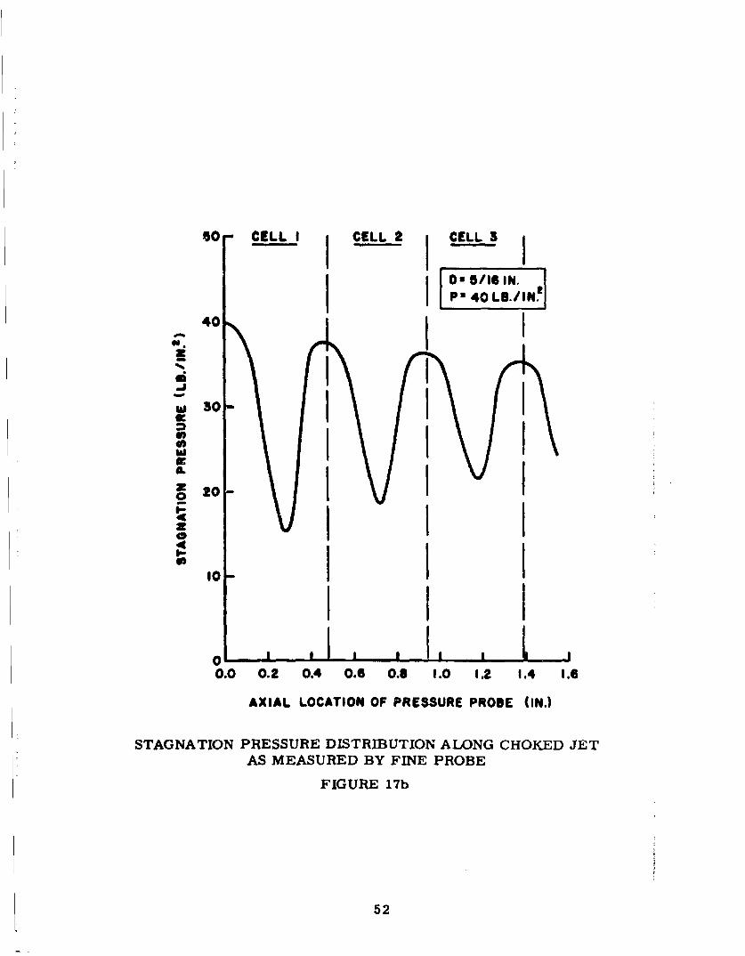
Figs. 17d show the periodically varying pressure along the axes of
Jets having various nozzle excess pressures, and the relationship of these
pressure changes to the cell structure. The amplitude of the variation can
be seen to Increase as the excess pressure was raised, until a point was
reached (at approximately 43 lb/in) where the normal truncation appearedIn the compression cones; thereafter the pressures measured on the jet axis
remained at a value of 8 lb/in2 or less, for some distance along the efflux,
and gradually increased as the subsonic jet core mixed with the surroundinghigh-velocity fluid.
50

40 CELL I CELL I CELL 3I- '
"I I-o I0
-
i-,n 0.018 IN. CIA.
S HYPODERMIC PRESSURE PROBE
-II
O i I I I I I.0 0.2 0.4 0.I 0.S 1.0 1.2 1.4 1.6 1.9
AXIAL LOCATION OF" PRESSURE PROBE (IN.)
STAGNATION PRESSURE DISTRIBUTION ALONG CHOKED JETAS MEASURED BY FINE PROBE
FIGURE 17a
51
O0 CELL I CELL I CELL 3
om 5/IS IN.40I iL"'5i'"I
-a o I
0 4 II40z!0
VI I10-
0
0.0 0.2 0.4 0.6 O.S 1.0 12 1.4 1.6
AXIAL LOCATION OF PRESSURE PROBE (IN.)
STAGNATION PRESSURE DISTRIBUTION ALONG CHOKED JETAS MEASURED BY FINE PROBE
FIGURE 17b
52

50 CELL I CELL. CELL 3
D 8 /16 N.o. a 4,,BINp. o ..,
40fiI I* I Iw 30
0 20-
10-4P
01I I
0.0 0.2 0.4 0.6 0.8 1.0 1.2 1.4 1.6 1.8
AXIAL LOCATION OF PRESSURE PROBE (IN.)
STAGNATION PRESSURE DISTRIBUTION ALONG CHOKED JETAS MEASURED BY FINE PROBE
FIGURE 17c
53

I
t
50 CELLI CELL 2 CELL 3 CELL 4
I D a5/Id IN.
40 P - 50 LB./IN'
S"I I30IL
z .
0 20
I0 1
0.0 0.2 0.4 0.6 0.8 1.0 1.2 1.4 1.6 1.8 2.0 2.2
AXIAL LOCATION OF PRESSURE PROBE (IN.)
STAGNATION PRESSURE DISTRIBUTION ALONG CHOKED JET
AS MEASURED BY FINE PROBE S
FIGURE 17d
54

Figs. 17 and 18 invite comparison with Figs. 14a to 14f where the regualarpressure periodicity coincides with the repeated frequency responses andthe aperiodic pressure distributions are linked with continuous oscilla-tion of the cavity at all nozzle-to-cavity spacings. It may be intimated herethat the aperiodic Jet flow is more unstable due to the high radial velocitygradients, and this will bear directly upon any criterion for oscillation.(Note the similarity to the effect of a destabilizing trip, a leading featureof which is its low velocity wake.)
The second pressure survey was undertaken to measure the stagnationpressures behind the detached shock present during cavity resonance. Inthis case the probe was of the form shown in Fig. 18, consisting of a bluntbody of the same profile as the cavities and having a narrow bore along its
axis which was connected to a Bourdon pressure gauge as before. When placedin a jet efflux, the detached shock took up a position in front of the probedepending on the stand-off distance. These results are plotted in Fig. 18 forvarying positions of the shock. They differ somewhat from the fine-probe
surveys insomuch as the characteristics have a much steeper slope in thepressure recovery zones and more pronounced peaks at the maxima and
minima.
During these pressure surveys it was found that the shock became un-stable when located in the pressure recovery zones of the jet effluxes. Thiscnnrlition has occurred mainly for pressures in excess of 35 lb/in2 andpersisted for only a short distance along the axis. For larger baffles theinstability was detected at lower pressures and over much wider limits.It may be surmised that the oscillations arose as a result of some formof resonance in the stand-off zones, since the wavelengths of the emittedsound appeared to be proportional to the distance of the shock from the probe-face--as postulated by Mprch in a theory for the instability of detached
shocks5 2
55

4 40 CELL I S.L CELL LL1
a:0 5/16 IN.N.
P30 LB3/IN.
w II0 I !I I, nnI
30
cw 20-
10. 5 I .01 A "
0
0.0 0.2 0.4 0.6 0.8 11.0 1.2 1.4 1.6 1.8
AXIAL LOCATION OF DCTikTCHED SHOCK (IN.)
STAGNATION PRESSURE DISTRIBUTION ALONG CHOKED JETAS MEASURED BY BLUNT PROBE
FIGURE 18a
56

40- CELL, I CELL 2 CELL 3I
I [IS30-
3.0
"I I I0 10I
! I
I I I I ,, I ,I--
0.0 0.2 0.4 0.6 0.6 1.0 1.2 1.4 1.6
AXIAL LOCATION OF DETATCHED SHOCK (IN.)
STAGNATION PISESSUHE DISTRIBUTION ALONG CHOKED JETAS MEASURED BY BLUNT PROBE
FIGURE 18b
57

t ii
50 CELL I CELL 2 CELL 3
S0 5 /16 IN,
P 40 LB./IN!
40 I
3•
10 1
- 'I I
0 '
00 0.2 0. 0.4 C 8 1.0 1.9 1.4 1.6
AXIAL LOCATION OF SMOCK DISC (IN.)
STAGNATION PRESSURE DISTRIBUTION ALONG CHOKED JETAS MEASURED BY BLUNT PROBE
FIGURE 18c
58
O5 I

However, when the excess pressures excerleed 43 lb/in2, severe in-stability of the shock disc was encountered at all points along the jet axisfor all baffle diameters, and consequently, pressure measurements behindthe shock were impossible. The instability took the form of very high-frequency oscillations, the radiated acoustic energy increasing as thesize of the baffle increased. Tests on a jet impinging on a 12-inch diameterbaffle indicated the presence of acoustic feedback phenomena, since anauxiliary baffle with its plane horizontal to the jet axis and held within afew diameters of the jet efflux was found to have a major influence on theacoustic output. As the auxiliary reflector was moved perpendicularly tothe jet flow, the acoustic output incrc'. ';d to a maximum and then fell off--in some cases the sound emission ceased completely--as the surfacetraversed a distance equal to one wavelength of the emitted sound. Fromthese observations it is inferred that the unstable nature of the aperiodicjet, together with sound reflected from the interaction zone back to thenozzle, gave rise to flow perturbations that served to drive the oscillations.
The data made available by the foregoing surveys showed that contribu-tary factors to the modus operandi of a Hartmann whistle might possiblydepend on (among other effects): feedback of disturbances from the cavityto the nozzle giving rise to jet perturbations, analogous to that giving riseto 'choked jet noise' 6 2 , effects arising from the oscillating shock wave alongrectilinear cavities, and detached shock instability. In consequence it wasnerecsary, in order to obtain a complete description of the mechanism, toconduct tests on an oscillating system in which as many of the above-mentionedeffects as possible could be ruled out as non-contributary.
Excitation of a Helmholtz Resonator by Periodic Jets
Several of the foregoing factors could be discounted when the oscilla-tions of a very low-frequency whistle were considered. This condition wasideally satisfied by adding a large-volume Helmholtz resonator to the endsof the previously described cylindrical cavities, as shown in Fig. 19. Thedevice, which was first used by Hartmann in his earliest studies of thephenomenon and referred to by him as the 'pulsator' appears to have beenoverlooked in all subsequent researches. By choice of suitable dimensions
59

4
e
4 N
& - 0-g
I. �'�'
I t� C yY�t' !
L L�
ILl
lt%
4
(p

for the resonant cavity it was possible to obtain an oscillatory systemhaving an extremely low frequency, with which all the flow variations
occurring during the course of a resonance cycle could be visuallyexamined. For the purposes of the study described here, a flangedcylindrical cavity of 6 in. diameter and 500 cu. in. volume was pro-vided with a set of replaceable end plates into which either 1/2 in. or
5/16 in. diameter orifices could be fitted, together with various formsof pressure-recording attachments, as required. The tubes formingthe resonator exits were usually 2 ins. long, or less.
For the conditions of small-perturbation theory, the Helmholtzresonator may be considered to oscillate by virtue of a mass of gas con-tained in the 'neck' moving with small amplitude against the resistanceprovided by compression of the remaining gas within the cavity; the
frequency of the resonator described above, when fitted with a 5/16 in.orifice would have been in the region of 40 c/s. However, when excitedby a periodic jet, the cavity was found to oscillate at a frequency varyingbetween 10 c/s and 0.5 c/s depending on the jet excess pressure and thespacing of the cavity and the nozzle. Since the wavelength at these fre-quencies was very much greater than the cavity's longest dimension, itwas evident that there could be no travelling shock-wave within the res -onator (such as occurred in. the rectilinear cavities) that could contributeto a mechanism for triggering each successive cycle, as postulated by
Hartmann.
Thus, the driving mechanism for the oscillations of resonant cavitiesplaced in spatially periodic jet effluxes cannot be critically dependenton feedback, or any 'tripping' of the cycle, by simple wave or shock motionwithin the cavity. It must account for the stable and unstable zones encoun-tered in the jet efflux, and also the lack of stable zones when the geometricperiodicity of the jet breaks down. The postulated mechanism should per-mit the oscillations to be quite impulsive in their commencement and ces-sation--there being generally no steady increase in oscillatory amplitudefrom a small disturbance, as is the case with most other forms of discrete-frequency sound generation by fluid flows.
61

The Mechanism of the Hartmann Whistle
With the help of studies of the Hartmann-Helmholtz whistle, a mecha-nism is suggested for the initiation and maintenance of the oscillations.Due to the expanded time-scale of the oscillations of this resonator it waspossible to examine, visually, a complete cycle without resorting to stro-boscopic illumination or phased shadowgraphs. The cycle appeared to beessentially the same as that of any small cavity, except that the flowin and out of the Helmholtz resonator was more clearly defined, the de-bouchement taking the form of a jet flow of variable excess pressure andthe zone of jet interaction being further removed from the vicinity of thecavity orifice.
The main features of its external flow variations appeared to be asfollows:
(1) Consider the cavity mouth to be located in the jet flow at a pointjust downstream of a cell division, i.e., at the downstream limit of one
of the unstable zones. C
(2) The jet initially flows into the cavity with the detached shocklocated very close to the orifice--a position hereafter referred to as the'downafream quasi -stable location' of the shock, as in Fig. 20a.
(3) As the cavity fills and the pressure within it increases, the separa-tion region of stagnation flow downstream of the shock grows in volume,I.e., the shock stand-off distance increases.
(4) When the increasing stand-off distance causes the shock to moveto where its stagnation pressure decreases (across the cell division) itIs impulsively transferred through a definite distance upstream, initiat-ing a radiated pressure wave as the cavity procedes to debouch in theform of a second spatially periodic jet. The shock is now located at the'upstream quasi-stable location', as in Fig. 20b.
62
S. .. . ;

0.
-~ -4
It It
U 0
E-4 H
En 0.
F4
00
g a.0. 0 63

(5) As the pressure in the cavity drops, the normal shock graduallymoves back downstream (Fig. 20c) until it reaches the limit of the range
of its upstream quasi-stable location, (Fig. 20d), when it impulsively moves
back to the cavity Mouth which then commences to refill for the next cycle.
(6) With the pavity further downstream the shock remains at its down-stream quasA-otable location, no oscillations being driven when the shock
does not cromp the cell division.
(7) Translation of the cavity in an upstream direction results in cavityoscillations of steadily increasing frequency until the upstream limit of the
unstable zone is reached.
(8) Pressure measurements showed that no over-pressures were
recorded at the closed end of the cavity, as occurred for the case of a2-inch cavity, (Fig. 10), the pressure variations remaining within the limits
of the stagnation pressure distribution encountered along the jet flow.
Since the interaction flows were shown to be of the form of two periodicJe•s that phenomenon was studied a little further by arranging for the axial
Impingement of two identical jet effluxes. An auxiliary air-supply mani-
fold, carrying a 5/16 in. diameter nozzle of the same internal profile as the
flxe nozzlewas mounted on a moveable cross-slide and connected via aflexible pressure-hose to a separate control valve. A tapping was provided
on the auxiliary manifold for measurements of the jet excess pressure. Byselecting a given nozzle-to-nozzle spacing and fixed jet pressures, any part
of the resonant cycle of a Hartmann-Helmholtz whistle could be 'frozen'and observed in detai. The shadowgraphs of Fig. 20 were obtained in thisway, and measurements of the shock separations and stagnation flow widths
were Obtained from which the following modus operandi was developed.
The postulated driving mechanism for any cavity excited by a periodic
Jet iW illustrated In Fig. 21 with reference to the case of a Helmholtzresonator. On the left, the over-all stagnation pressure distributions of
the main jet and the variable-pressure jet emerging from the cavity aredisplayed, and in the right-hand column the corresiponding interacting jet
flows are illustrated.
64

JET PRESSURE, CAVITY PRESSURE, JET
Pot P03 NOZZLE CAVITY
35 -35
30 -3 SOC A
25 -25 DOWNSTREAMQUASI- STABLE
20 20 LOCATION
35 35
"30 , CAVITY
25 25 OEBOUCHING
"20 PO5 .335L8/IN2
3o- --35 2
-•30- 30
w25- - 25 P0327 &
520 20
_o
3 5- -35-0 -30
25 25
20. /,S
25•// - O 15 2&35 -35
30 -30
CAViTY25 25 RECHARGING
20 20
0 0.25 0.5 C.T5 1.0
AXIAL DISTANCE, (IN.)
STAGNATION PRESSURE DISTRIBUTIONS OFINTERACTING, PERIODIC JETS
FIGURE 21
65
U)tI I

(1) The cavity receives fluid from the Jet flow until the pressureinside the cavity is equal to that existing behind the detached shock inIts downstream quasi-stable position--a value that will vary with thelocation of the cavity (and thus of its normal shock) along the jet axis.
(2) U the cavity orifice is just downstream of a cell division, thenthe shock wiU be in a region where the stagnation pressure distributioncurve maximizee.
(3) If the detached shock crosses the cell division (the selected loca-tion is in the region of the downstream termination of one of the unstablezones), due to either an increase in jet pressure and the consequent length-ening of the cell dimensions, or movement of the cavity in an upstreamdirection, then the shock disc will be transferred to a region where stagna-tion pressure drops rapidly with axial distance. (This corresponds tomovement of the shock from a position of neutral equilibrium to one ofunstablg equilibrium. Movement in the opposite direction merely transfersthe separation zone to a point of stable equilibrium where pressure in-creases with distance from the cavity--the so-called 'stable zone').
(4) Since, in this condition, the cavity pressure exceeds the stag-nation pressure corresponding to the shock's location, the pressureImbalance results in the shock moving upstream to the next point of quasi- 3stable equilibrium.
(5) The cavity proceeds to debouch, the high excess pressure withinit causing the emergent fluid to form a periodic jet efflux. Between thetwo impinging Jets there will be an interface with equal pressures oneither side. Consequently the stagnation flow of each jet can be approx-imated by a wall flow of the jet impinging on an infinite baffle--the separa-tion of the shock from the interface being determined by the jet excesspressure. The upstream and downstream shocks take up positions in the
two jet effluxes at points producing equal stagnation pressure.
66

(6) As debouchment continues, the cavity pressure falls and the inter-
acting flow zone moves toward the cavity mouth until the equal stagnation
pressures at the common "plane" can no longer be maintained. This flow
pattern then collapses and the periodic jet flow again enters the cavity, the
beginning of the next cycle.
(7) This proposed mechanism appears to be valid for any location of the
detached shock as long as it is in a region of the jet efflux where the stag-
nation pressure behind it falls with distance Irom the cavity orifice. At
points where the pressure differential between the stagnation pressures
of the two quasi-stable points is reduced, the re-cycling time for the cavity
will be of shorter duration, and in consequence the frequency of oscillation
of a Helmholtz resonator will increase as the cavity is moved upstream
through an unstable zone.
(8) The re-cycling time of this series of events for any cavity is
evidently dependent on the rate at which the cavity charges and debouches,
and hence the frequency of oscillation will also be governed by (although
different from) the resonant frequency of the cavity. Reviewing Fig. 7 in
the light of the proposed driving mechanism it can be seen that the time
taken for the 2-inch cavity to debouch (the half-periodic time) was less
than the time taken for the normal shock to make a complete transit to
its maximum outer quasi-stable position, although the mechanism for the
driving of the oscillations seems identical to the above.
(9) All cavities will thus tend to oscillate at their fundamental fre-
quency when the normal shock has sufficient 'axial freedom' in which to
make large-amplitude oscillations. As the cavity is moved upstream through
the stable zone the distance over which the shock can oscillate is reduced
and the mode of oscillation jumps to a some higher harmonic frequency,
where the system oscillates with reduced linear movement of the shock.
67

CONCLUDING REMARKS
This tentatively proposed mechanism for the initiation and maintenanceof the oscillations of a Hartmann whistle when excited by a strictly periodicsupersonic jet amplifies that which was originally postulated by Hartmannin 1924. Some shortcomings of the original theory have been clarified,
largely by the identification of the bi-stable condition of the stagnation
point. Attention is now being turned to set up a suitably rigorous theoreti-cal description of the mechanism, the important role of the jet structure
and the associated variable stagnation pressure (and therefore variable
entropy) in the jet having been established. This throws some light uponsuch questions as the failure of the two-dimensional system to oscillate(different pressure distribution) while the hydraulic analog, recently
brought into use, does so. Work is still in progress in respect of the dif-fering aspects of what seems to be a somewhat similar mechanism for the
instabiMity for very high-pressure aperiodic jet flow, and for the de-stabiliz-Ing trips causing oscillations of an otherwise stable whistle configuration--particularly in relation to the case of the 'stem-jet'.
68
__________

REFERENCES TO LITERATURE
1. A. A. Regier and H. H. Hubbard, "Response of structures to highintensity noise", Noise Control, 5, 13-19, 58, 1959.
2. I. Elias, "Sonic combustion control", Sound, 2, 6, 8-12, 1963.
3. R.M.G. Boucher, "Utrasonics in processing", Chem. Eng., 89, 83-100.
1961.
4. P. Greguss, "The effect of sound on combustion processes", Soviet
Physics-Acoustics, 8, 330-334, 1963.
5. P. Greguss, "The application of airborne and liquid-borne sounds toindustrial technologT1", Ultrasonics, 2, 5-10, 1964.
6. R. Shkol'nikova, "Acoustic air-jet generators for aerosol coagulation",
Soviet Physics-Acoustics, 9, 295-300, 1964.
7. R. C. Chanaud, "Experiments concerning the vortex whistle", J. Acoust.
Soc. Am., 35, 953-960, 1963.
8. A. Powell, "Mechanisms of aerodynamic sound production", NATO AGARD
Rpt 466, 1963.
9. F. Galton, "Hydrogen whistles", Nature, 27, 491-492, 1883.
10. V. Gavreau, "Gen~rateurs pneumatiqueb d'ultra-sons intenses", Acustica,
8, 121-130, 1958.
11. E. Brun and R.M.G. Boucher, "Research -n the acoustic air-jet
generator: A new development", J. Acý..Ast. Soc. Am., 29, 573-583, 1957.
12. T. Vrebalovich, "Resonance tubes in a supersonic flow field", Jet
Propulsion Lab., Calif. Inst. of Tech., Tech. Rpt. 32-378, 1962.
13. C. L. Dailey, "Supersonic diffuser instability", J. Aero. Scd., 22,733-749, 1955.
14. C. L. Dailey, "Investigation of supersonic diffuser instability", Univ.
of Southern California, USCEC Rpt. 41-3, 1955.
15. K. Oswatitsch and I. Teipel, "Die Pulsationen von Stossdiffusoren",
Z. angew. Math. Mech., 9B, 462-478, 1958.
69
16. W. H. Sternbentz and J. C. Evvard, "Criterions for prediction andcontrol of ram-Jet flow pulsations", NACA TN 3506, 1955.
17. A. Ferri and L. M. Nucci, "The origin of aerodynamic instability ofsupersonic inlets at subcritical conditions", NACA RM LSOK30, 1951.
18. R. H. Johnson, "Instability of hyperejonic flow about blunt bodies",Physics of Fluids, 2, 526-532, 1959.
19. H. Sprenger, "Thermal effects in resonance tubes", Mitteilungen aus
dem Institut fUr Aerodynamic an der E.T.H., Zurich, No. 21, 18-24,' 1954.
20. Jul. Hartmann, "Oem en ny Metode til Frembringelse af Lydsvinginger",Dan. Mat. Fys. Medd., 1, 1019.
21. Jul. Hartmann and Birgit Troll, "On a new method for the generationof sound waves", Phys. Rev., 20, 719-727, 1922.
22. Jul. Hartmann and Birgit Troll, "New investigations on the air-jetgenerator for acoustic waves", Dan. Mat. Fys. Medd., 7, 1926.
23. Jul. Hartmann and Birgit Troll, "A new acoustic generator. The air-jet generator", J. Scl. Instruments, 4, 101-11, 1927.
24. Jul. Hartmann and Birgit Troll, "Modus operandi of the air-jet pulsator",SDan. Mat. Fys. Medd., 10, 4, 1930.
25. Jul. Hartmann, "On the production of acoustic waves by means of anair-jet of a velocity exceeding that of sound", Phil. Mag., 11, 926-948,1931.
26. Jul. Hartmann, "La gineratrice acoustique a jet d'alr", Journal dePhysique, 7, 49-57, 1936.
27. Jul. Hartmann, "The Hartmann acoustic generators", Engineering, 142,491-492, 1936.
28. Jul. Hartmann and E. V. Mathes, "Die experimentelle Grundlage zumEntwerf des akustichen Luftstrahlgenerators", Akust. Z., 4, 126-136,1939.
29. Jul. Hartmann,, "The acoustic air-jet generator", Ingeni~rvidenskabeligeSkrifter, Copenhagen, No. 4, 1939.
70

30. Jul. Hartmann, "Der akustiche Luftstrahlgenerator", Die Umschau, 25,2-4, 1939.
31. Jul. Hartmann, "Construction, performance and design of the acoustic
air-jet generator", J. Sci. Instruments, 16, 140-149, 1939.
32. Jul. Hartmann and F. Lazarus, "The radiation of the acoustic air-jotgenerator derived from direct observations of the amplitude of theaerial vibrations of the oscillator", Phil. Mag., 29, 140-147, 1940.
33. Jul. Hartmann and E. TrudsO, "Synchronisation of air-jet generatorswith an appendix on the stem generator", Dan Mat. Fys. Medd., 26,10, 1951.
34. Jul. Hartmann and F. Larris, "The air-jet generator as a means ofsetting up waves in a liquid medium", Dan. Mat. Fys. Medd,., 26, 11,1951.
35, L. Ehret and H. Hahnemann, "Ein neuer Schall-und Ultraschallgeberzur Erzeugung starker :ntensitkten in gasen", Z. techn. Physik, 23,245-266, 1942.
36. R. Kling and J. Crabol, "Sur la production d'ultrasons au moyen dejets gaseux", Comptes Rendus, 229, 1209-1211, 1949.
37. L. E. Savoy, "Experiments with the Hartmann acoustic generator",
Engineering, 170, 99-100, 136-138, 1950.
38. M. Palme, "Contribution k l'Ntude de la sirbne de Hartmann", NuovoCimento, Atti del Convegno Internazionale de Ultracustica, 7, 260-277,1950.
39. H. 0. Monson and R. C. Binder, "Intensities produced by jet-typeultrasonic vibrators", J. Acoust. Soc. Am., 25, 1007-1009, 1953.
40. E. Brun and R.M.G. Boucher, "Recherches sur le ge'n~rateur acoustiquek jet d'air"%, Chim. et Ind., Ge. Chim., 76, 137-151, 1956.
41. R.M.G. Boucher and E. Brun, "Research on the 'Multiwhistle' acousticair-jet generator", The Eng. Digest, 17, 511-514, 1956.
42. V. P. Kurkin, "Sound generated by a gas jet siren", Soviet Physics-Acoustics, 7, 357-359, 1962.
71

43. V. P. Kurkin, "Oblique-shock gas-jet sound radiator", Soviet Physics-Acoustics, 8, 344-346, 1963.
44. S. Young White, "Experimental iltrasonics", Audio Eng., 33, 20-23,1949.
45. P. Bugard, "Etude de l'action biologique de bruits complexes de niveaulevd. (Rdgion ultrasonore du spectre)", Ann. Telecomm., 7, 139-143,
1952.
46. M. le Landals, "Research on the stem-jet acoustic whistle", UltrasonicNews, 4, 3, 7-10, 1961.
47. 0. Nomoto, 'Vorking characteristics of the Hartmann acoustic air-jetgenerator". (In Japanese), J. Acoust. Soc. Japan, 8, 34-35, 1952.
48. J. C. Gravitt, "Frequency response of an acoustic air-jet generator",
J. Acoust. Soc. Am., 31, 1516-1518, 1959.
49. P. A. Thompson, "Resonance tubes", M.I.T., Ph.D. Thesis, 1960.
50. S. Faim, "A photographic study of resonance tubes", M.I.T., S.M.Thesis, 1960.
51. B. Hartenbaum, "Hydraulic analog investigation of the resonance tube",M.I.T., S.M. Thesis, 1960.
52. K. A. Mrch, "Shock instability in the Hartmann air jet generator",Tech. Univ. of Denmark, Fluid Mechanics Lab. Rep LFM R 63-2, 1963.
53. M. Sibulkin and T. Vrebalovich, "Some experiments with a resonancetube in a supersonic wind tunnel", J. Aero/Space Sci., 25, 465-466,1958.
54. E. Lettau, I'Messungen an Gasschwingungen Grosses Amplitude inRohrleitungen", Deutsch Kraftfahrtforshung im Auftrag des Reichs-Verkehrsministeriums, 39, 1-17, 1939.
55. T. E. Suttles, "A theoretical interpretation of the production of weakperiodic shock waves in a column of gas vibrating near the acousticalresonant frequency." New York Univ., Ph.D. Thesis, 1962.
56. I. M. Hall and C. J. Berry, "On the heating effect in a resonance tube",J. Atro/Space Sci., 26, 253, 1959.
72

57. J. Wilson, "An investigation of resonance tubes", Cornell Univ.,M. Ae. E. Thesis, 1958.
58. J. Wilson and E. L. Resler, "A Mechanism of resonance tubes",J. Aero/Space Sci., 26, 461-462, 1959.
59. A. H. Shapiro, "Shock waves and dissipation in a resonance tube",J. Aero/Space Sci., 26, 461-462, 1959.
60. A. H. Shapiro, "On the maximum obtainable temperature in resonancetubes", J. Aero/Space Sci., 27, 66-67, 1960.
61. P. E. Howick and R. D. Hughes, "Pressure and temperature effects inresonance tubes", M.I.T., Dept. of Mech. Eng., S.B. Thesis, 1958.
62. A. Powell, "On the mechanism of choked jet noise", Proc. Phys. Soc.,66, 1039-1056, 1953.
73

DISTRiIBUTION LIST
Agency Copies Agency Copies
Chief of Naval Research CommanderDrpartment of the Navy Naval Ordnance Laboratory
46 C omma nd or
466 1 U1.S. Naval Ordnance Tent Station
468 1 Pasadena Annex
*~~~30 Ehi.g Fothl llinoi I u ineenCommand ins Off icer Panadnapoi8 MalfrylaOffice of Navel Research rchi Libisary
* Branch Office Comndn5 ffcr n i8co207 Sumert2t StreetNew Ytor 10, MasYskachuNvlsarettsgnerngLboatr
AomnndoleMryln* Commanding Officer Naval COrdne 750 taio
Office of Naval Research CiaLkClfriBranch Office Comaunt OffJ W ickr20Nav Micigan B Av9enuedNaa ~miltrveUiNhiwaYork, NlliYois I Cambridgen3, asacusttCommand Ing Of ficer Cnaommning Offylerand DrcoOffice of Naval ReseaIrnh Atn!dierwatrys LaoatIBranch OfficeFotTmbl2030 Weast 2r4en Street NComLondon, ConfmndecticutoPasadorna11, California1 S Nav In T arhnicalnLibrary n aortr
Commanding Officer Cnaommndis, Oficryland DrcoOffice of Novel Research U.tn S.Naod ie 75 en0LaoarBranch Office Pammnamdityg Offiorid1000 Gear0, StreetT ndNvl diisrtveUi
Fleet Pont Office.Navsalhset Postirauate SfTchologDi Yrk, etYo r Cmobtride 39 Malifrsacuet
Ofieo Naval Research LaboraatoryboundnLaLoraary100 asigto 2ree D.C.Ne odoCnnciu
Commn:Cdins f000er Commanding Officer and Director2020ofNvl eerc .S Naval s Eleftroni Laoatory tr
2027 6rnic ,Clfri SaprntDende2ntl~oriU.S.Gd Naa4223rdat cho
DeavlRtmenarfche Naboaoy Commndery57 Weshinnton 2S, D).C. NrokNvlSiyr
341 edr 20 1 Commandenr fie adDrco
4212 1 Naval Baetrne cLbrtr2027 6 BSonioklyn, N awiYorki
Chief, Bureau of Navlip aosDepartment of the Navy Commanade rW~aphititon 25, D.C. Bostonk Naval Shipyard
Attn Cnodes 305 1 Porsmonu29, Mirsiaca uIt33RR 1RU41 Commander
3Philaelphirk Naval ShipyardComndn4ffcr2n1 irco Naval Base
De'rimen ofthe avyCommander1 no253 D.C Portsout Naval Shipyard
Attn, dem 9-2 1 Btton29 DesignhDivision
DaFlid MTiyon M oude Bain hldlha1,Pnslai6/25/63 , .C

Ajse7 copies Agency CopiesChmarl estnr V lyr Society of Novel Architects ad Mparm.U h. lS. tov eel ipyer r-ax 1eeqrm
CommI.ent, Officerelm No Yo 6. No YorkILogCose Novl hipar Webb Instituate of NvlArchite 1 reLost; Reach 2. CaG llot Tr~e~a'fLibrar Paz
Atmmi"4ic: wryNe.wporal Rhoderer isa dnac tte Institute of Mathematical SciencesNAllort, Researc 0%l~.d New York UaivetolityCmat nd eearh Now York 3, New YorkCoear Hderbo oe hv Allot Professor J. J. StokerNay illS. Fleet Poweflic The Johns lopkins lUniversitySon Vramciaco, Calfforsi.
Baltimore Is. IfmgalatidCommanderAltai Professor . . PhillipsSOD VIrcamel Novel %hipardSam rrone laco 24. Califeriti
DiructorCommander
A Plied Phroies LaboratoryMoer tilan Nava IShipyard 6621 hn lite, k~i4 .UniverdityVallejo Caiage Ifes Silver Spring, MarylandCeommnndlrin Officer
Cahirernia lntiltaate of TechnologyU.S Irmleeerch Office Pamaginna 4. California
Desham. bNor Carolies Altts Hiydrodynamics LaboratoryC o m m anderP ro fe s mor 1'. Y . W u 1
Id . 1 .. A m T e ep r ai e R a a o Univeruuity of CaliforniaDi'vo Copsesti Berkeley 4, CalilforniaTraspottion Cirpisi Attn: Dopatento uiernFortn aestm Vrioni CeI
Professor J. V. WilimosesOffice of Technical ServieseDepartment of CoamuereWashington 25. D.C. I Iowa Institute of hlydrailc RemearchDefense Documentation Center
Stats haler1i0 y f,11 wCamerom Station
IoaCityIwAlexandria, Virginia 10 Ae:Professor Li. RadorserFluid Mechanics Sweiss Harvard UnivereityNational Barnes of Standlarib Cambridge 38, MasacmehusettsWashin log 25 D C. Altai Profoessor C. BirkhoffAuni Ofr. C. .ShaurIProfessor
G. IF. CarrierDirector Ie~rhCne
rLeme ndSaeAmihrgo University of MiciuigraLangley Plaid, Virginia Allil- l'sglieering Research matiltsts
Pro'feaaur W. W. Wi iimorth= %retrc Aer abratory dsnarte DirectorNtosAramtesand Spc dimsrto Ordmanmo. Research LaboratoryMofet Wow CaliforniaI Pamoaylvdals State University
Director niversity Park. Ponss IvtolaLewis Research Center AtiO kdiyt'atoqar.,oroernsa on aod Space Admmnlagreties Dr: C. k Wisliveaga
Dir~gr -Director
Divieje St. Anthony Falls Hydroolic LaboratoryICOo&ga cua Fettlintion MUnsesof 1.MissenotWashington. D.C. IAlttni awaern H. SilbermanAir Farce Office of Seiaulfum RseaorchPoeme
.C SruWokaeshlgo 5 D .Ciio Massachusetts Inst keto of Technology11' oblo ton 25 , .C .C sAm ridge a;. M aesach oseueAttai Profeseer P. Mandelmet dem Salie&e
Professor C. C. Lisn21101 Comatiltleme Avon"e, NWWauhiagl.. 2S. D.C.I
Ms~aeeralSeobetesa Librr leotisate for Filid Mechaslcenow York Ill. Now York 6 ~idMahmtc
CUsivers ofMaryiamd~)j~~MouonaSoun (2)Alttn: Professor J. M. Burgers
Agency Copies Agency CopiesGraduate School of Aeronautical College of EsgimeeringEngIneeringoCornell Univermity University of CaiorniaIthaca, New York DAtls, CaliforniaAitla Professor W. R. Soars Atal Professor S. R. KetmBIlro-wn UniversityProvidence 12 Rhode IslandAllot Dr. N. E. Meyer
Stevens Institute or TechnologyDavidson LaboratoryHoboken, New JerseyAtt.r Dr. S. J. Lukaulk
iepurtnicnt of Mathematipsensucleer olytechnic InstituteTroy, New YotkAttn: Professor R. C. DiPrimo
Southwest Research instituteS500 Culebra RoadSan Antonio 6, TexasAttns Dr. II. N. Abramaion
Department of Aeronautical EagineeaulgUniversity of ColoradoBoulder, o oloradoAttnt Professor M. S. UberolDr. R. R. KroichnsnPeterboroughNew Hampnhire
Dr. A. RitterTherm Advanced Research DivisionTherm, IncorporatedIthaca, New YorkDr. Ira DyerBolt Beranek, and Newman, Inc.SO houlton StreetCambridge, Massachusetts
Hydronautica, IncorporatedPIndell School RoadHoward CountyLaurel, Mary landAttn: Mr. P. Eisonberg, President
Dr. J. KotikTechnical Research Group, Inc.Route 110Melville, New York
DirectorHudson LaboratoriesDobbs Ferry, New York
Armour Research FoundationIllinois Institute of TechnologyChicago 16, IllinoisAttat Library
Oceenica, laccwrporotedPlainview, Lonlaland, New YorkAttn. Dr. Paol apipn
Dr. 0. SternllchtMechanical Technology Incorporated968 Alba.nyShaker RoadLatham, New York
University of CaliforniaLoo Anjcle, CaliforniaAttn. Prolessor A. Powell
Fluid Motion & Sound (3)6/25/63

DOCUMENT COWIROI. DATA - RD
-; CIIV c"oosoe to PapearT sgguA'? C LA681"IChSIe.
University of California a661u
EXPERIMENTS CONCERNING THE HARTMANN WHISTLE
's 11SERIPTVI wORi 1 Iipe offto amu owsve deruh
NoneI *UT0K@(8)(&,n *mem.kt ftemus.m W"
Smith, Timothy J, S.Powell, Alan
it WSIm~ne "eaa sav 70 TOTAL 06 O PG 1. we, fopgapSep~tember 1964 68 8 2
me 6"U"AY on4" e Noor 233(62) on ateiAin S 02060T WIUmews)
4L:*g V He R-00g-01-01 64-42NR 062-.299/l11-19-62 D&grXXS 0.vj (Any.,..-ow~m 00mpS 00
None
On request until copies exhausted. Reports Group, Rm. 7549, Engr. III
I .SUPPI. UTMYUh' "YU 8g 0f"R S. IT"W me Av CTMIVINone Dp fNv FudDnmc rnh
Wsshinlgloil 25- D_. CIt.ASTfCTThe Hartmnann whistle, in its most basic configuration. consists of a
flat-bottomed, cylindrical cavity which io axially aligned with a supersonic air jetof the same, diameter. Disc rete -frequency oscillations of the enclosed air columnare driven at large amplitudes when the cavity io located within certain regions ofthe cellular structure of the J~t. An optical and acoustical study of the phenomenonis described, together with that of the Hartmann ' pulsator' . In the latter form thewhistle has the small cavity replaced by a large Helmnholtz-type resonator with thesame orifice diameter. resulting in a large-amplitude aeroscoustic oscillator witha Oleriodic time of several orders of magnitude greater than for the regular whistle.The underlying cause of the newly discovered bistable condition of the normal' shock-disc' located in the airstream between the nozzle and the cavity orifice ioan important aspect which makes possible a (presently qualitative) theory ofoperation which accounts for the principal features of the Hartmann whistle and itsIdirect derivatives. Some other aspects still requiring further elucidation and whictare the subject of continuing effort are mentioned. The Report includes a briefreview of the currently available literature pertaining to the phenomenon.
D D sp~t 1473 _________________

WON~~~~ -Uc
h -11
0 -O -n - 'j tkin A LINK a Wil C~I~S U
IHartmnann whistleI I IISound generationUrstoady flow
I I1. ORIOINAMO~ACTIVITY Wili th*it~arssae by seurity~ahctt uesin stendawi a¶D.Yfmentg ;of the mi~taoe. subcomtacter. uuomito. Deportmew of Den. each or%"ns activity orther oaesietoe (coee,.e "hr loW I ti (I) "Quaalified feqk-&4evs mop obtain ceptss of Ibisthe topm* ?Evwft frem DOG" P
2a. EZPMT 60UCITY CAIWEATIOle Roaw the ovi (2) "Ferois. .amosemc.meot *A d ths~msimsolef of thisall se--1Vewlp cimu cetioiB ad the rap"e. maiaites ~w rephe. by DOC tome asos .eshaeee4"Mooteicled Doe"a Is Ltatti" %MUR@is toW be In nee"diasee with ImI.I it.ssmawa towaideten (4 "U. L Cl~emvrsment s l mec ay a1 obtato crvi.-s of
this q. report 6MO foam DOC. Oher quoe aleld DOC26. MROM~ Amemaai 00 -s R4 to~~ Specified is DOD Di. seam *hall respeet thtosose-itiw 1 1.0 ated Ann" Poeaw. IedaatMIa MomaL gtrathe gnq aiie.. Alsai. where aepilemble. ohs. thes eptimegictorkqai haee boom good for Cieinp) 3 OW q dreti 4a a aer. (4) 014. 11, mlliter apncie. imy obtain co~iiii c. Ohio
lied. re~Mpart dityci fram 0=ODC ther q'za.f.a w..3. XWOUT TrAM SOWa the c"01411 M"p01 title go al @hall remstm Usmeughcapita lettistO. Titlss toall *soft should be mainulainasllIt a MmomileaWt fill* Commel itsseected with"w cIasalftewti epe se~ftl4Qaties.m. shw.M aoosshncotheo in all capital. is parsaussia CS) "All distributaion of ti oe scmeltQdlqsed Olaey fellowias the wele. &Iad DOC Soe*, Owel re"Wea 0111Iwatag
4. 011CRIPTIVUt 11TES Ii appropriate. soexist te 4 of .0I ~so, a&* istorks, p~ror . smmesip. oWd. ofxItthe ropmo has Ivoan furqiehed to the Office at Tsr haiaailGive the liasise ilitle.en sW specific rWepesIF peeld as services. Deartan rt ofd. Carrt-oft. Ifa lee to ithe public, lads.00-01 Cato We~ feet 064e met I"e Price. it kmven.S. AUTHMO3 3-Mo tbs ~*~) of sahlbo(s) 65 zh5Uat as IL SUPPLUISMIARY IOTW U~s e edd oitioeal aspi....ac I& the rapecs Eodnt Lm adwi. first almow, Mide. oiltia 1.noes
Wi nlj t. W.~ bw~ * padý * eac IN~t *( a . TUS .u.w *1 OU.V M IYthe priacipal asa'heci las 4146eelats mil~milf foeW .4m. 12. 111 ORI0O MIUTAAtVT ie h aetOW dqertmeatel pmjst office or luboratory waoi (pay-a6 RXWOW DAME 3.4.r Sthe doe of Sthe report as day, ined get) Iriae ressearch and devolopmastw. Include ad**%*.mtath*twpot.~ isi asUlhes, o f pul tCio 199 AUTRACT. Rqta. as aitstract Stvtnu a brefe and (actualY& the L .ap..K. OF PAI.R The wuh %I pae*ummary n! Mshe oumeal Indlcxtsv9 of he [email protected]. seven thuu hp ... tTAL UE*OF PR Te to2~ qe LU'S it mop else appear elbouhe,. ish -)e body or the. vothasce! re,absuld follow inwfISl Sugltamlles peoUodies. Lo6 eider tite part. Ii edditiolawispecsf to "itqird. a ro*Iha"satle sh~et t &% I;%afte of #We5 codiolail lolemyatief be. attarsted p1
76- NVMWZX OF WREFRONCEs Rtati the Iso aub otfhsl euilohtst biatvicasiu s.i3 ulecei~g rltt let th .496be he asaoaIined. Rich paregrnph of the abstract smalt wed wI
S& Ca ONTRACT Oft GRANT WtJMER: If s~p isse. enter an iadicatiat of the o*liitar security claaesiiacet~or ut the Asthe aeplIcaalt mwnet of the ceetuec a paet usode which IM&O Sthe ImlWee reprs 'pesented ms rMi (sp. ec, ,,_rl
Gb 8 SS. PPVEjCT NUM8Z1t Etie, the appropriate Over. the aGOW~tsd 1069lth to frm 5 V 2 woods.ouleqy oct msh4 apa~lctati mu mbee tas proecsh eder. et1 4.TI 90OGD1 Kay wordsm gre tchascally meaningful tarmsembpojot "mthe, sytemismbors tok onibe et. W00"phrasesG that c111PCem tirte a fepei eOd mop be used asft. ODOIN01ATORSS PV60RT WWMIW3UU. &mor the sf1 Woe.ean .so eefo esawlogiag the vepet Re, words am*, k,otel report stetki by whitb the 4eoumnot will he idea if~id selecte so that em. seeursty c leastfit tia"is. mom rqamed idonti.and controlled by the orlginsill.¶ aatlivtt. V14 A86W umbee t noe". outic me qaapmatet nuedeI doealptims. trade naame wiijr
be 16qeatio sohis Pope". ____ petat oda "11110 4110801111111c 16C6160111. may be tmeod. so k*a. OTMM RLPORT NUVEZG)- li the ravenl ba lie wetd" but will bet. ollowed by, as indi..atkoa *I techntical c,,A. 4aassignee any other report emshsor (olh.. by the e4idIRa' teat. lbM 64saaiamet of links. rase, and weights is optiona:of Ly the apseopmo. Wlee ester this amimbe(m).I10. AVAILAMLITYfLWMTAT1OPN NTICLS Zate, any lint,
itatleag as twit r diismmgoiatiee of the ftpiet. &tLer thenf I"ea
SKscuity Claasica~fetion