al-tr-1993-0017 ad-a270 - defense technical … ad-a270 473 ! a preliminary electro-optic evaluation...
TRANSCRIPT

AL-TR-1993-0017 AD-A270 473 !
A PRELIMINARY ELECTRO-OPTIC EVALUATION OFPROTOTYPE SURFACE MODE LIQUID CRYSTAL
R SHUTTER FOR NUCLEAR FLASHBLINDNESS PROTECTION
MSTR Michael W. Mayo, Captain, USAF
0 Craig M. Bramlette, Staff Sergeant, USAF
N OCCUPATIONAL AND ENVIRONMENTAL HEALTH DIRECTORATEOPTICAL RADIATION DIVISION
DBrosGi 8111 18th Street OT IBrooks Air Force Base, TX 78235-5215 ELECT
L July 1993
A -
B Final Technical Report for Period September 1989 - June 1990
0RAT Approved for public release; distribution is unlimited.
0
RY io 93-23776
93 1>3 038
AIR FORCE MATERIEL COMMAND_....__ BROOKS AIR FORCE BASE, TEXAS

NOTICES
When Government drawings, specifications, or other data are used for any purpose other than inconnection with a definitely Government-related procurement, the United States Government incurs noresponsibility or any obligation whatsoever. The fact that the Government may have formulated or in anyway supplied the said drawings, specifications, or other data, is not to be regarded by implication, orotherwise in any manner construed, as licensing the holder or any other person or corporation; or asconveying any rights or permission to manufacture, use, or sell any patented invention that may in anyway be related thereto.
The Office of Public Affairs has reviewed this report, and it is releasable to the National TechnicaiInformation Service, where it will be available to the general public, including foreign nationals.
This report has been reviewed and is approved for publication.
MICHAEL W. MAYO, Captain, USAF ROBERT M. CARTLEDG1,- , USAF, BSCProject Scientist Chief, Optical Radiation Division
REPOT DCUMNTATON AGEForm AprovedREPOT DOUMENATIO PAG OMB No.0704-0188
Publi r"ong burden for this collection of Information is eiae to average I hur per response, including the time for revWeng Inructions, awrchi existng data sourcs, ennd maintaning the data nesded, and compilet arid rWing the collecton of ir n Send comments regarding this burden sstimaie or a" Wer aspect of "thuis on
information, includingg ons kir reducing this burden, to Washington Headquarters Services, Director"at fr IMnfonation Operations and Reports, 1215 Jefferson Damis Highwa, Suite1204. AtlIngton, VA 22202-430, "nd to the Office of Management and Budget, Paperwork Reduction Proct (0704-0188), Washington. DC 20603.
1. AGENCY USE ONLY (Leave blank) 2. REPORT DATE 3. REPORT TYPE AND DATES COVERED
July 1993 Final - September 1989- June 1990
4. TITLE AND SUBTITLE 5. FUNDING NUMBERS
Preliminary Electro-Optic Evaluation of Prototype Surface Mode Liquid PE - 62202FCrystal Shutter for Nuclear Flashblindness Protection PR - 7757
TA - 02
6. AUTHOR(S) WU - 78
Michael W. MayoCraig M. Bramlette
7. PERFORMING ORGANIZATION NAME(S) AND ADDRESS(ES) 8. PERFORMING ORGANIZATIONArmstrong Laboratory (AFMC) REPORT NUMBEROccupational and Environmental Health Directorate AL-TR-1 993-0017Optical Radiation Division8111 18th StreetBrooks Air Force Base, TX 78235-5215
9. SPONSORING/MONITORING AGENCY NAMES(S) AND ADDRESS(ES) 10. SPONSORING/MONITORING AGENCYREPORT NUMBER
11. SUPPLEMENTARY NOTES
12a. DISTRIBUTION/AVAILABILITY STATEMENT 12b. DISTRIBUTION CODE
Approved for public release; distribution is unlimited.
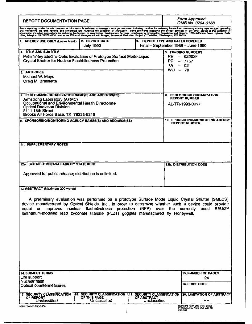
13. ABSTRACT (Maximum 200 words)
A preliminary evaluation was performed on a prototype Surface Mode Liquid Crystal Shutter (SMLCS)device manufactured by Optical Shields, Inc., in order to determine whether such a device could provideequal or improved nuclear flashblindness protection (NFP) over the currently used EEU/2Planthanum-modified lead zirconate titanate (PLZT) goggles manufactured by Honeywell.
14. SUBJECT TERMS 15. NUMBER OF PAGESLife support 24Nuclear flash 16. PRICE CODEOptical countermeasures
17. SECURITY CLASSIFICATION [&SECURITY CLASSIFICATION 19. SECURITY CLASSIFICATION 20. LIMITATION OF ABSTRACTOF REPORT OF THIS PAGE OF AULTRACT
Unclassified Unclass-,d unclassified ULNSN 7540-01-280-5500 Standard Form 298 (Rev 2-89)
Prescribed by ANSI Sid Z39-18290-102
CONTENTS
PageEXECUTIVE SUMMARY ............................. 1
Results . . . . . . . . . . . . . . . . . . . . . . . . . . . . . . . . . . . . . 1
BACKGROUND .................................. 2
Nuclear Flashblindness Protection - PLZT ................ 3Operation of the Surface Mode Device .................. 3
EXPERIMENTAL METHOD ........................... 6
Spectrophotometry .............................. 6H aze . . . . . . . . . . . . . . . . . . . . . . . . . . . . . . . . . . . . . . 6Activation and Closure Times ....................... 6
RESULTS ..................................... 7
Spectrophotometry .............................. 7Activation and Closure Times ....................... 9
DISCUSSION ................................... 13
REFERENCES .................................. 15
DTIc QUALuy iNsPEMsCT
OTIS ODAK sDTIC TAB 0UnanounOed 0Justification- I
Di stribu tI M/ 00 .
Availability 960
Avai and/orbg Speo 1.2
Wi JON
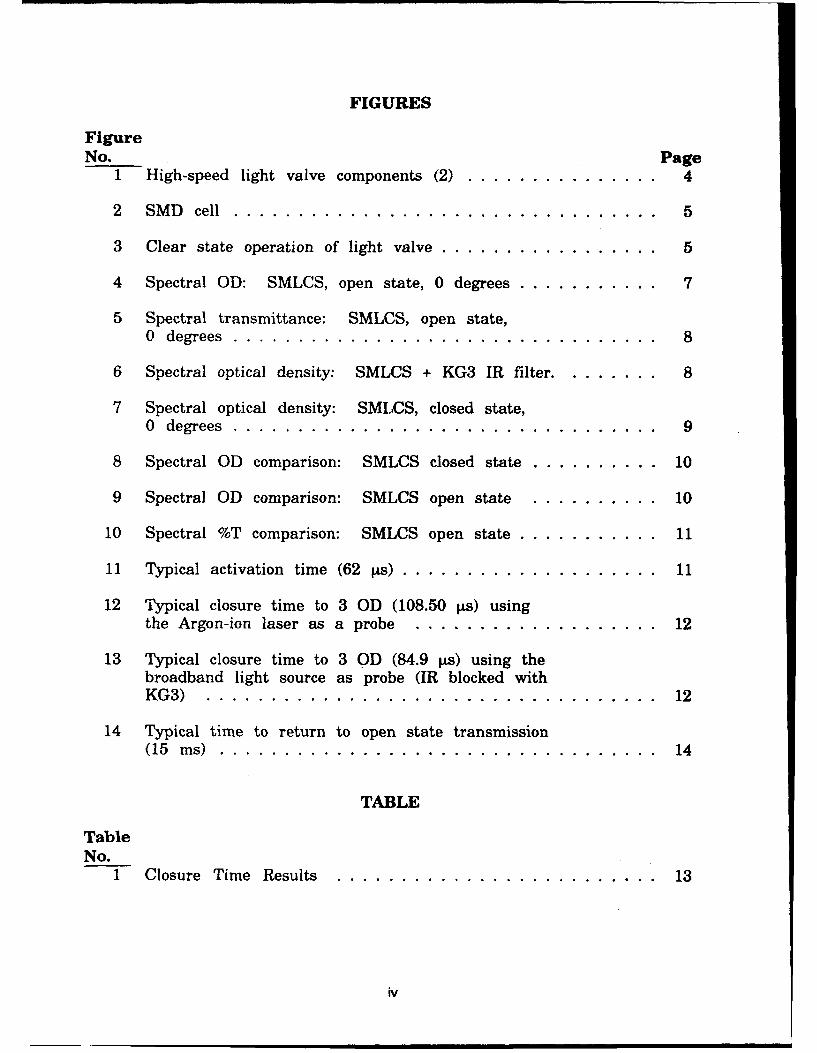
FIGURES
FigureNo. Page
1 High-speed light valve components (2) ............... 4
2 SM D cell .. . . . ... .. .. .. . .. . .. . .. . . .. . . .. . . 5
3 Clear state operation of light valve ................. 5
4 Spectral OD: SMLCS, open state, 0 degrees ............... 7
5 Spectral transmittance: SMLCS, open state,0 degrees ....... ................................. 8
6 Spectral optical density: SMLCS + KG3 IR filter .......... 8
7 Spectral optical density: SMLCS, closed state,0 degrees ....... ................................. 9
8 Spectral OD comparison: SMLCS closed state ............. 10
9 Spectral OD comparison: SMLCS open state .............. 10
10 Spectral %T comparison: SMLCS open state ............... 11
11 Typical activation time (62 ps) .......................... 11
12 Typical closure time to 3 GD (108.50 9s) usingthe Argon-ion laser as a probe ...... ................... 12
13 Typical closure time to 3 0D (84.9 jks) using thebroadband light source as probe (IR blocked withKG3) ......... ................................... 12
14 Typical time to return to open state transmission(15 ms) ......... .................................. 14
TABLE
TableNo.
1 Closure Time Results ........ ....................... 13
iv

PRELIMINARY ELECTRO-OPTIC EVALUATIONOF PROTOTYPE SURFACE MODE LIQUID
CRYSTAL SHUTTER FOR NUCLEARFLASHBLINDNESS PROTECTION
EXECUTIVE SUMMARY
A preliminary evaluation was performed on a prototype Surface Mode LiquidCrystal Shutter (SMLCS) device manufactured by Optical Shields, Inc. Theactivation and closure times were measured to determine whether such adevice could provide equal or improved nuclear flashblindness protection (NFP)over the currently used EEU/2P lanthanum-modified lead zirconate titanate(PLZT) goggles manufactured by Honeywell. In addition, a basic opticalcharacterization was performed to include spectrophotometry, haze, and laserdensitometry. The device sent to Armstrong Laboratory (AL) was an off-the-shelfSMLCS designed for use in an electronic welding heh, 't. Optical Shield-,Inc., added an infrared (IR) cut-off filter to make it more suitable for the NFPapplication. However, the application of this IR filter coating was not optimized,and one side of the SMLCS was not suitable for testing. Therefore, all testswere performed on only one side of the device. For these reasons, and inorder to meet initial program goals, a full-scale evaluation was not performed.Only basic performance characteristics were assessed since the military versionof the SMLCS will most likely be different from this prototype.
Results
Spectrophotometry was performed on the device in both its clear and darkstates at various angles and rotations to determine spectral optical density,spectral transmittance, photopic and scotopic luminous transmittance, meanultraviolet (UV) transmittance, and chromaticity coordinates. Both the photopicand scotopic luminous transmittance were measured to be 34.0% at normalincidence, zero degree rotation perpendicular to the normal axis. The photopicand scotopic luminous transmittance dropped to 18.2% and 15.5%, respectively,at 450 off normal. These transmittance values are not absolute measurementsbut are only good for relative changes due to the inherent polarizationdependency of the SMLCS. The mean UV transmittance was 0.0% for all testconditions. Likewise, chromaticity coordinates were within the neutrality limitsfor all circumstances.
The SMLCS was found to be very sensitive to the polarization of theincident light source. The spectrophotometer used during this evaluation israther strongly polarized in one plane (linear polarization). After an orthogonal900 rotation with respect to the incident beam direction the results were vastlydifferent. The photopic and scotopic luminous transmittance dropped to 6.1%and 5.1%, respectively. To obtain a true transmission reading, a randomlypolarized broadband light would have to be used as the source and transmission
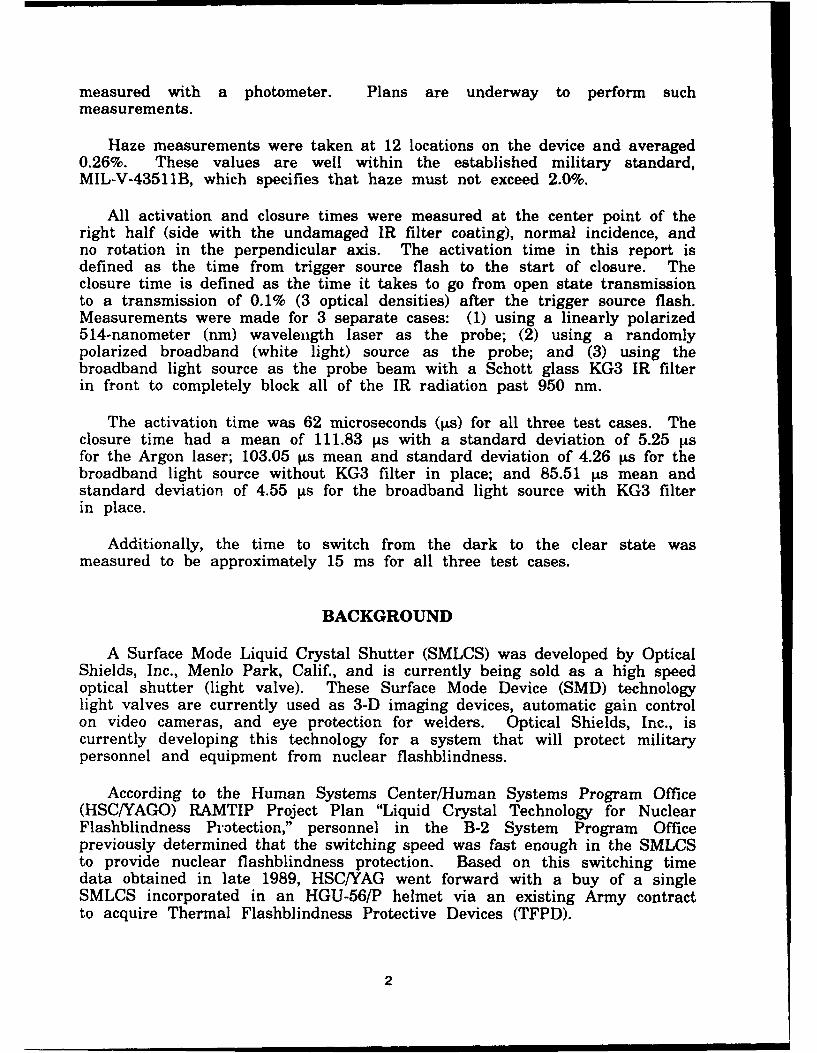
measured with a photometer. Plans are underway to perform suchmeasurements.
Haze measurements were taken at 12 locations on the device and averaged0.26%. These values are well within the established military standard,MIL-V-43511B, which specifies that haze must not exceed 2.0%.
All activation and closure times were measured at the center point of theright half (side with the undamaged IR filter coating), normal incidence, andno rotation in the perpendicular axis. The activation time in this report isdefined as the time from trigger source flash to the start of closure. Theclosure time is defined as the time it takes to go from open state transmissionto a transmission of 0.1% (3 optical densities) after the trigger source flash.Measurements were made for 3 separate cases: (1) using a linearly polarized514-nanometer (nm) wavelength laser as the probe; (2) using a randomlypolarized broadband (white light) source as the probe; and (3) using thebroadband light source as the probe beam with a Schott glass KG3 IR filterin front to completely block all of the IR radiation past 950 nm.
The activation time was 62 microseconds (lps) for all three test cases. Theclosure time had a mean of 111.83 [s with a standard deviation of 5.25 [isfor the Argon laser; 103.05 Rs mean and standard deviation of 4.26 t~s for thebroadband light source without KG3 filter in place; and 85.51 pAs mean andstandard deviation of 4.55 Vs for the broadband light source with KG3 filterin place.
Additionally, the time to switch from the dark to the clear state wasmeasured to be approximately 15 ms for all three test cases.
BACKGROUND
A Surface Mode Liquid Crystal Shutter (SMLCS) was developed by OpticalShields, Inc., Menlo Park, Calif., and is currently being sold as a high speedoptical shutter (light valve). These Surface Mode Device (SMD) technologylight valves are currently used as 3-D imaging devices, automatic gain controlon video cameras, and eye protection for welders. Optical Shields, Inc., iscurrently developing this technology for a system that will protect militarypersonnel and equipment from nuclear flashblindness.
According to the Human Systems Center/Human Systems Program Office(HSC/YAGO) RAMTIP Project Plan "Liquid Crystal Technology for NuclearFlashblindness Protection," personnel in the B-2 System Program Officepreviously determined that the switching speed was fast enough in the SMLCSto provide nuclear flashblindness protection. Based on this switching timedata obtained in late 1989, HSC/YAG went forward with a buy of a singleSMLCS incorporated in an HGU-56/P helmet via an existing Army contractto acquire Thermal Flashblindness Protective Devices (TFPD).
2
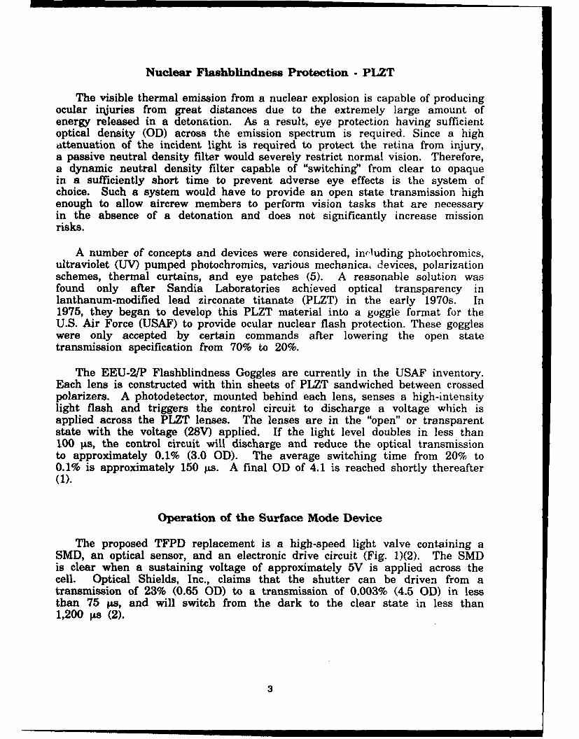
Nuclear Flashblindness Protection - PLZT
The visible thermal emission from a nuclear explosion is capable of producingocular injuries from great distances due to the extremely large amount ofenergy released in a detonation. As a result, eye protection having sufficientoptical density (OD) across the emission spectrum is required. Since a highattenuation of the incident light is required to protect the retina from injury,"a passive neutral density filter would severely restrict normal vision. Therefore,"a dynamic neutral density filter capable of "switching" from clear to opaquein a sufficiently short time to prevent adverse eye effects is the system ofchoice. Such a system would have to provide an open state transmission highenough to allow aircrew members to perform vision tasks that are necessaryin the absence of a detonation and does not significantly increase missionrisks.
A number of concepts and devices were considered, including photochromics,ultraviolet (UV) pumped photochromics, various mechanica, devices, polarizationschemes, thermal curtains, and eye patches (5). A reasonable solution wasfound only after Sandia Laboratories achieved optical transparency inlanthanum-modified lead zirconate titanate (PLZT) in the early 1970s. In1975, they began to develop this PLZT material into a goggle format for theU.S. Air Force (USAF) to provide ocular nuclear flash protection. These goggleswere only accepted by certain commands after lowering the open statetransmission specification from 70% to 20%.
The EEU-2/P Flashblindness Goggles are currently in the USAF inventory.Each lens is constructed with thin sheets of PLZT sandwiched between crossedpolarizers. A photodetector, mounted behind each lens, senses a high-intensitylight flash and triggers the control circuit to discharge a voltage which isapplied across the PLZT lenses. The lenses are in the "open" or transparentstate with the voltage (28V) applied. If the light level doubles in less than100 tis, the control circuit will discharge and reduce the optical transmissionto approximately 0.1% (3.0 OD). The average switching time from 20% to0.1% is approximately 150 Rs. A final OD of 4.1 is reached shortly thereafter(1).
Operation of the Surface Mode Device
The proposed TFPD replacement is a high-speed light valve containing aSMD, an optical sensor, and an electronic drive circuit (Fig. 1)(2). The SMDis clear when a sustaining voltage of approximately 5V is applied across thecell. Optical Shields, Inc., claims that the shutter can be driven from atransmission of 23% (0.65 OD) to a transmission of 0.003% (4.5 OD) in lessthan 75 ps, and will switch from the dark to the clear state in less than1,200 Rs (2).
3

Op~tical Sensorn•
Electronic Drive Surface Mode DeviceCircuit
Figure L High-speed light valve components (2).
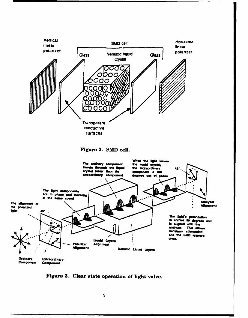
The SMD cell is shown in Figure 2 and consists of a 7 rtm thick, birefringentnematic liquid crystal material sandwiched between transparent electrodesurfaces and crossed polarizers (3). With 5V applied, the material directlynext to the substrate maintains its original orientation while the material inthe center of the cell orients in a direction parallel to the applied electricfield (4). Changing the applied voltage causes changes in the surface layerwhich in turn alters the cell optical properties (2). Due to the birefringentcharacteristics of the nematic liquid crystal, the phase of polarization of thelight passing through the cell is shifted by a degree proportional to thethickness of the surface layer. Since the surface layer thickness is dependentupon the applied voltage, the optical properties will vary with varying voltages(6).
The clear state operation of the light valve is shown in Figure 3. Randomlypolarized light passes through the first polarizer to become linearly polarized,then passes through the liquid crystal cell where it is resolved into twocomponents. The ordinary component is aligned parallel to the long axis ofthe liquid crystal molecules while the extraordinary light component is alignedperpendicular. The ordinary component travels faster through the surfacelayer of the cell and undergoes a 1800 shift in relation to the extraordinarycomponent. This action results in an effective 900 polarization rotation whichwill allow for passage through to the analyzer (2).
4
Vertical SM ca Horizontallinear ___________________ inearpolarizer GasNemtc fiqud Gaspolarizer
crystal
00/04,0
Transparentconductivesurfaces
Figure 2. SMD cell.
When the NgtM hey..The ardhw*y component the "ql wyoKatraIl through the "ql the extraordinay 4crytal Mfasery I t ai thefot fphs
The light compmponent
The aignmw ofAnalyzerMe. polarizedAlgmn
The lights polarizationIs shofed go degrees andls aligned with the-nya. This aMoms
m~nknm ansnxieftanW the SUD appearsdlear.
ParzrAlignment
Ordinary Extraordinary
component Component
Figure 3. Clear state operation of light valve.
5
For dark state operation, the voltage is discharged in order to orient allof the liquid crystal material parallel to the electric field. In this state,linearly polarized light travels through the cell parallel to the long axis ofthe crystal and is -aerefore unaffected by the birefringent properties. Sincethe ordinary anCi .xtraordinary component of light will travel through the cellat the same -,seed, the two components are in phase and the direction ofpolarization will not change. The light will then strike the analyzer 900 outof alignment and be absorbed.
EXPERIMENTAL METHOD
Spectrophotometry
Spectral scans were performed on the material in both the open and closedstate at 0, 15, 30, and 45 degrees with respect to normal. The SMLCS wasalso tested after rotating the device 90" in a plane orthogonal to the incidentbeam. All measurements were made through the center of the lens havingthe undamaged infrared (IR) filter coating. A Perkin-Elmer Lambda 9UV/VIS/NIR spectrophotometer was used to obtain spectral transmittance,spectral optical density, mean UV transmittance, photopic and scotopic luminoustransmittance, and chromaticity coordinates. The spectral range scanned wasfrom 200 - 1200 nm in 1-nm increments.
Haze
The haze of an optical element is that percentage of transmitted lightwhich, in passing through the material, deviates from the incident beam byforward scattering outside of a 2.50 cone. Haze was determined by a HazeguardXL-211 Hazemeter. The system was calibrated with a GTS-2202 test standardand is accurate ±0.1% for samples having a haze less than 14%.
Activation and Closure Times
All activation and closure times were measured at the center point of theright half (side with the undamaged IR filter coating), normal incidence, andno rotation in the perpendicular axis. The activation time in this report isdefined as the time from trigger source flash to the start of closure. Theclosure time is defined as the time it takes to go from open state transmissionto a transmission of 0.1% (3 OD) after the trigger source flash.
Measurements were made for 3 separate cases: (1) using a linearlypolarized 514-nm wavelength laser as the probe; (2) using a randomly polarizedbroadband (whiti ight) source as the probe; and (3) using the broadband lightsource as the probe beam with a Schott glass KG3 IR filter in front to
6

completely block all of the infrared radiation past 950 nm. A white light,xenon photoflash was used to simulate the nuclear flash and serve as thetrigger source for the digital storage oscilloscope.
RESULTS
This section presents the data obtained from the experiments designed toevaluate the performance of the SMLCS. As mentioned earlier, a full-scaletest was not completed on the prototype SMLCS because of the probabletechnical changes in the military version.
Spectrophotometry
Figures 4 and 5 depict the open state spectral OD and transmittance,respectively, of the prototype SMLCS as designed for use as a protective shieidfor welders goggles.
Figure 6 shows the spectral OD of the SMLCS in combination with a KG3IR filter to completely filter the IR radiation past 950 nm. The addition ofthis filter, or a coating having the same spectral characteristics, may resolvepossible problems which may cause the "leakage" of near-IR radiation. Theaddition of such a filter should not significantly lower the open state transmission.
1064.0 2.99 532.0 - 0.401050.0 -, 2.91 530.0 - 0.39694.3 - 0.54 514.0 - 0.30647.0 - 0.53 488.0 - 0.41632.2 - 0.5654.0
I-.
( 3. 3.0U) 3. 0z
12..J 2.02.
U
N
1.0n. 1.00
0 , 0
200 400 Go0 800 1000 1200
SL WAVELENGTH (nrm)
Figure 4. Spectral OD: SMLCS, open state, 0 degrees.
7

SAMPLE OPTICAL SHIELDS OPEN STATE(PEFIUKNI
PHOTOPIC LUMINOUS TRANSmITTANCL" 34.0Z Chromaticity Ceora.:SCOTOPIC LUMINOUS TRANSHITTANCE, 34.-9 X - 0.305MEAN UV TRANSMITTANCE. 0.02 Y - 0.389
Z - 0.325
100 100
z2 o Bo
1-4
(nU)S60 60
U)z4 40 40
I--
;e 20 20
0 0200 400 S00 o00 1000 1200
EL• WAVELSNG7H (nm)Figure 5. Spectral transmittance: SMLCS, open state, 0 degrees.
3.o 3.0
0
.1 2.0 2.04U
0 0 to200 400 600 800 1000 1200
IwvEAVENGTH (nm)
Figure 6. Spectral optical density: SMLCS + KG3 IR filter.
The fully closed state yields an attenuation factor of greater than four (4OD) in the entire visible spectrum. The spectral optical density of the SMLCSis the closed state shown in Figure 7.
8

1064.0 - 3.17 532.0 > 4.00
1060.0 a 3.17 530.0 > 4.00
694.3 > 4.00 514.0 > 4.00647.0 > 4.00 485.0 > 4.00
532.8 • 4.00T0 4 0
I--
S3.03.0Z
02.0
-J 2.0.4
I- .0. 1.0
0
0 0
200 400 600 o00 IGJO 1200
Figure 7. Spectral optical density: SMLCS, closed state, 0 degrees.
Figure 8 displays the minimal decrease in closed state protection in thenear-IR spectral region. As shown in Figure 6, an improved IR filter coatingcould be incorporated to prevent this shift in protection from 1100 to 1000 nmas shown in Figure 8.
The variations caused by the polarization of the incident light are clearlyshown in Figures 9 and 10. Figure 9 compares the spectral OD results whenthe device is rotated 900 with respect to the incident linearly polarized lightfrom the spectrophotometer. Likewise, Figure 10 compares the spectraltransmittance scans. The photopic luminous transmittance (dark adaptedvision) changes from 34.0% to 6.1% and the scotopic luminous transmittance(dark adapted vision) changes from 34.9% to 5.1%.
Activation and Closure Times
The activation time was 62 jAs for all three test cases (Fig. 11). Theclosure time had a mean of 111.83 ps with a standard deviation of 5.25 Psfor the Argon laser (Fig. 12); 103.05 ps mean and standard deviation of 4.26jLs for the broadband light source without KG3 filter in place, and 85.51 tLsmean and standard deviation of 4.55 ýts for the broadband light source withKG3 filter in place (Fig. 13).
9

SAMPLE. OPTICAL SHIELDS LIGUID CRYSTAL. CLOSED 0 DEGREES
(PERKINI
SAMPLE 0 2 : OPICAL U..1IE~ LUl= CRYTAL.. C 30 0EGRIEEEPERKINI
4.0
I--
Ln 30 3.0
w0 3.
J 2.04U
I- .
IL 1.0 1.0
0
200 400 S00 Soo 1000 12C-0
":/r1a/2C Zy SLO WAVELENGTH (rMm)
Figure 8. Spectral OD comparison: SMLCS closed state.
0 and 30 degrees in plane rotation.
SAMPLE. OPTICAL SHIELDS OPEN STATE(PERKINI
SAMPLE 0 2 : PTI.CAL SHIELDG LCS 90 GO IMCMDENT
4.0 4.0
I-,
Ufl 3.0 3.0zw
J 2.0
U
nL 1.0
00 l0
2ao 400 500 Soo 1000 1200
Figure 9. Spectral OD comparison: SMLCS open state.Normal incidence: 0 and 90 degrees.
10

SAMPLE: OPTICAL SHIELDS OPEN STATE[PERRXINI viiuC 1=~ =~ufTAW N 342
SWoIC u = JIAMDT 34.925AMPLE 0 2 : OPTCAL. SHW.. L g 90 E IEE 4
~PE~JINJ PBMPZC L~UMMM TRANTIUNP9 G44s=cJ.•]mouzc L3U TZ3mTm 5. azScoMPIC LMI TU•=M 3.al
100
zC g0 .O
UlU)Ul' 60 , 60
z
z4 d 40
0 20 20
0 0Inn 600 800 1000 1200
Figure 10. Spectral %T comparison: SMLCS open state.Normal incidence: 0 and 90 degrees.
! I I
At 62.O00is T/div 50 ,is
Figure IL Typical activation time (62 ps).Upper trace is photoflash, lower trace is SMILCS response.
•H41 ' ,1

At 108.S 50 s T/dLv 50 go
Figure 12. Typical closure time to 3 OD (108.50 gtw) usingthe Argon -ion laser as a probe.
Ilm,
31
see1- - - - - - - - - -
-- --
- -Ieee e ---- --e~aee
4 -
at.. 84.9Pe T/div20,s
Figure 13. Typical closure time to 3 0OD (84.9 gAs) using thebroadband light source as probe (JR blocked with KG3).
12

The activation times were not a function of the probe beam polarizationangle or wavelength. We feel that this time could be significantly decreasedwith improved design of the electronics. The activation time of the currentlyused PLZT is only 12 ps.
The following table summarizes the closure time results. Apparent fromthese results is the polarization sensitivity of the device and the effect ofnear-IR radiation leakage.
Table L Closure Time Results
Case 1 Case 2 Case 3ARGON.ION LASER (514nm) BROADBAND UGHT SOURCE BROADBAND UGHT SOURCE
(With KG3 Filter)- Linrly polarized randomly poarized - randomly polarized- coherent incoherent - incoherent
100.2 104.8 90.5106.9 109.0 83.1116.8 100.2 82.1112.3 99.7 84.9107.4 109.7 76.8109.9 102.2 85.1119.8 103.6 83.8116.5 103.5 84.8109.7 103A6 91.5115.5 94.2 92.5119.5112.8108.6109.7
MEAN: 111.83 MEAN: 103.05 MEAN: 85.51STD DEV: 5.25 STD DEV: 4.26 STD DEV: 4.55
The time to return to a fully open state did not change when tested duringall three condit-.ois. The fully closed to fully open time response was 15 msfor all cases (Fig. 14). This time response also appears to be a function ofthe electronics and the electro-optic nature of the SMLCS.
DISCUSSION
A full-scale test was not completed on the prototype SMLCS because ofprobable technical changes in the military version. Nevertheless, we feel thatthe data collected thus far depicts the SMLCS as technically feasible for NFP.Additionally, the limited evaluation performed will allow us to design moreoptimal test systems. ii-ca- this evaluation we have gained vital informationon the technical areas which require the most extensive investigation whiletesting the military version of the SMLCS nuclear flashblindness protectiondevice.
13

1 i-- ii ---- I""i .. ... ... " •,. l• •. "i!" .... ..... ... ....
.. ..... ... ..I .A n. .*.. ...- "i
1 .
At 15.100 ms T/div 5 um
Figure 14. Typical time to return toopen state transmission (15 ms).
The polarization sensitivity of the device should not be a major concernsince the radiation from a nuclear detonation is randomly polarized as is mostnaturally occurring illumination, nor should there be any significant effectsfrom the cockpit lighting since it should also be randomly polarized light.
14
REFERENCES
1. Lindsey, R.L. Electro-Optic Performance of PLZT Lasers. USAFSAM-TR-88-13, September 1988.
2. Optical Shield, Inc., Technical Note "High Speed Light Valve," 1988.
3. Fergason J.L. "Use of Strong Surface Alignment in Nematic Liquid Crystalsfor High Speed Light Modulation," Optical Shields, Inc., Tech Note.
4. Fergason, J.L. "Performance of a Matrix Display Using Surface Mode," IEEEDisplay Research Conference, 1980.
5. Allen, R.G., Labo, J.A., and Mayo, M.W. "Laser Eye Protection," SPIE OE'LASE Proceedings, 1990.
6. Yariv, A. Optical Electronics, CBS College Publishing, 1985.
i5