alarm install app user guide - wireless security - … install app user guide i contents contents...
TRANSCRIPT

Alarm Install App User Guide
I
Contents
Contents .........................................................................................................................................................I About this publication ...................................................................................................................................III
Who should read this guide ...................................................................................................................III Notices ...................................................................................................................................................III Support ..................................................................................................................................................III
About Alarm Install App ............................................................................................................................... IV
Chapter 1 Setting up the Alarm Install App ....................................................................................................1Supported devices .........................................................................................................................................2
Prerequisites ..................................................................................................................................................3
Configuring the PowerManage server ....................................................................................................3
PowerManage MMI console settings ..............................................................................................3
PowerManage web server settings .................................................................................................4
Approving installer access .............................................................................................................................5
Self-monitoring approval .........................................................................................................................5
Setting up installer alert notifications ..............................................................................................5
Central Monitoring Station (CMS) approval ............................................................................................6
Alarm Install App configuration ......................................................................................................................7
Software download and installation ........................................................................................................7
Direct and remote access requirements .................................................................................................7
Connecting to an alarm panel using direct access .................................................................................8
Connecting to an alarm panel using a WiFi network ......................................................................8
Connecting to an alarm panel using USB and USB OTG cables (Android devices only) ..............9
Connecting to an alarm panel using remote access ........................................................................... 12
Remote access modes ................................................................................................................. 12
Registering the Alarm Install App email account ......................................................................... 12
Registering a panel ...................................................................................................................... 13
Deleting a registered panel .......................................................................................................... 13
Accessing an alarm panel using direct access mode ................................................................................ 14
Troubleshooting ........................................................................................................................... 15
Accessing an alarm panel using remote access mode .............................................................................. 16
Chapter 2 Managing the security system..................................................................................................... 19Alarm Install App interface.......................................................................................................................... 20
Customer Information (Info) screen ..................................................................................................... 20
Editing customer information:....................................................................................................... 21
Diagnostics screen .............................................................................................................................. 22
Deleting a device: ......................................................................................................................... 23
Reviewing panel configuration and status: .................................................................................. 23
Reviewing device configuration and status .................................................................................. 24
Editing device configuration ......................................................................................................... 24
Enrolling a new device ................................................................................................................. 25
Radio Frequency testing .............................................................................................................. 26
Walk Test screen ................................................................................................................................. 27
Configuration screen............................................................................................................................ 29
Retrieving the panels configuration parameters .......................................................................... 30
Archiving the configuration parameters ....................................................................................... 30

II
Deleting an archived configuration ............................................................................................... 31
Viewing and changing configuration parameters ......................................................................... 31
Specifying the time to retain configuration parameters ................................................................ 32
Panel Log screen ................................................................................................................................. 33

III
About this publication
Who should read this guide
This guide is intended for installers, technicians, and support engineers who are configuring and troubleshooting an alarm security system.
Notices
© 2019 Tyco security Products. All Rights reserved.
The trademarks, logos, and service marks displayed on this document are registered in the United States [or other countries]. Any misuse of the trademarks is strictly prohibited and Tyco will aggressively enforce its intellectual property rights to the fullest extent of the law, including pursuit of criminal prosecution wherever necessary. All trademarks not owned by Tyco are the property of their respective owners, and are used with permission or allowed under applicable laws. Product offerings and specifications are subject to change without notice. Actual products may vary from photos. Not all products include all features.
Support
EMAIL: [email protected] INTERNET: EMEA: - https://www.tycosecurityproducts.com/TS_ContactDetails.aspx
APAC: - https://www.tycosecurityproducts.com/A_TS_ContactDetails.aspx

IV
About Alarm Install App
The Alarm Install App provides the convenience of configuring an alarm security system from your mobile device or tablet. You can configure the security panel either on site or from a remote location. If you are on site, the security panel can be hidden and there is no requirement for a wireless keypad. If accessing the panel remotely, response and troubleshooting times can be significantly reduced as there are no travel requirements. You can download the Alarm Install App from the Apple App Store or Google Play App store.

1
Chapter 1 Setting up the Alarm Install
App

2
Supported devices
The Alarm Install App can be installed on following devices:
Apple devices, iOS version 9 or later
iPad
iPhone
Android devices, version 4.3 or later
Tablet
Smartphone
To install the Alarm Install App, use the following links:
https://itunes.apple.com/us/app/alarm-in/id1276105878?mt=8 https://play.google.com/store/apps/details?id=com.visonic.configurator.alar
m_in

3
Prerequisites
Before installing the Alarm Install App, you must configure the PowerManage server. If using the remote access function, ensure that the User App for example, Visonic-Go is installed on the user’s mobile device.
Configuring the PowerManage server
Before you use the Alarm Install App, the interactive settings parameters on the PowerManage server must be configured. The parameters are configured from the PowerManage MMI (Man Machine Interface) console.
PowerManage MMI console settings
Configure the Alarm Install App settings on the MMI console before you install the Alarm Install App. To configure the Alarm Install App settings on the MMI console, complete the following steps:
1. Log on to the PowerManage MMI console.
2. On the MMI menu, go to Settings > Application configuration > Interactive > Interactive options.
3. Select the Installer interactive is enabled for new panels check box, to
enable access from the Alarm Install App to new panels.
4. Optional: To allow a user to control Alarm Install access to their alarm panel,
complete the following fields:
a Select the Allow user to approve installer login check box, to enable access to an alarm panel only when the user grants permission using the User App.
b Enter the number of minutes that the installer can access the panel in the Approve timeout field.
The following example shows the Interactive configuration pane and the options you can select to control how the Alarm Install App connects to the alarm panel.
4
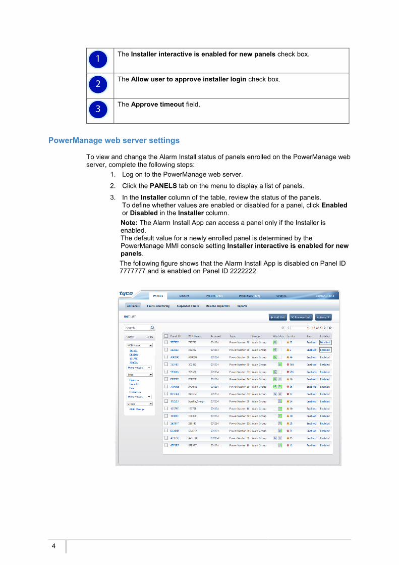
The Installer interactive is enabled for new panels check box.
The Allow user to approve installer login check box.
The Approve timeout field.
PowerManage web server settings
To view and change the Alarm Install status of panels enrolled on the PowerManage web server, complete the following steps:
1. Log on to the PowerManage web server.
2. Click the PANELS tab on the menu to display a list of panels.
3. In the Installer column of the table, review the status of the panels. To define whether values are enabled or disabled for a panel, click Enabled or Disabled in the Installer column. Note: The Alarm Install App can access a panel only if the Installer is enabled. The default value for a newly enrolled panel is determined by the PowerManage MMI console setting Installer interactive is enabled for new panels. The following figure shows that the Alarm Install App is disabled on Panel ID 7777777 and is enabled on Panel ID 2222222

5
Approving installer access
You can connect to a panel locally or remotely if you use the Alarm Install App. If you use a self-monitoring remote connection, the owner of the alarm system must approve installer access. For Central Monitoring Station (CMS) monitored systems, the CMS operator approves access.
Self-monitoring approval
To allow the installer access to an alarm panel, the user must approve access from the Panel Settings menu of the User App. This permission is required only if Allow user to approve installer login option is selected in the PowerManage MMI console. See PowerManage MMI console settings for details. To approve access to the panel from the User App, complete the following steps:
1. Open the App, select the panel and enter the master access code.
2. Tap the menu icon and then select Panel Settings > Remote installer access.
3. The Remote Alarm Install access window appears. Tap OK to approve and
allow the installer access to the panel.
Note: The Alarm Install App can access a panel only for the time period defined
in the MMI console Approve timeout field. See PowerManage MMI console
settings for details.
Setting up installer alert notifications
The installer alert notifies you when the installer requires access to a panel from
the Alarm Install App.
To configure an alert notification, complete the following steps:
1. Open the User App.
2. Tap the menu icon and select Panel Settings > Notifications.
Menu

6
3. Flick through the push notification settings and select Notice events. Set the
visual, audio or vibration alert options.
For example if a Heads-up visual notification is selected, you receive an
alert when an installer is trying to log on to a panel, as shown in the following
alert notification examples:
Visual alert notification from the device
Visual alert notification within the Visonic-Go App
Central Monitoring Station (CMS) approval
For CMS remote access only, the CMS operator must approve access to the panel from the PowerManage web server:
1. Log on to the PowerManage web server.
2. Click the SYSTEM tab on the PowerManage menu and then from the
USERS MANAGEMENT pane, click Installers.
3. In the table, find the newly registered account. In the Actions column click
Accept. Note: In self-monitoring mode, the new registration details are automatically
accepted.

7
Alarm Install App configuration
The installer using the Alarm Install App can access and configure alarm security panels using a direct or remote connection. If you use direct access you connect through the local WiFi network to the PowerMaster-360 or PowerMaster-360R alarm panel. Using remote access, you can access all Visonic security alarm panels that are connected to the WAN and registered on the PowerManage server.
Software download and installation
Download and install the Alarm Install App. The first time you start the Alarm Install App the Terms of Use screen appears, review the terms and tap Accept to start the installation.
Direct and remote access requirements
The following prerequisites are required for direct access: A connection to the PowerMaster-360 or PowerMaster-360R alarm panel.
This connection can be a WiFi connection to the panel’s private local WiFi network. For Android devices, you can connect to the panel using USB and USB OTG cables.
The mobile device must be within range of the panel’s WiFi. The following prerequisites are required for remote access:
All panels must have cellular or Ethernet connections, or a combination of both. You can connect to all alarm panels that are connected to the WAN.
All panels must be enrolled on the PowerManage server before connecting to the panel using remote access. The PowerManage server must be configured for remote access.
The following figure shows the connection page, where you select either a direct or remote connection.

8
Connecting to an alarm panel using direct access
You can select Direct access and connect to a PowerMaster-360 or PowerMaster-360R using the panels, private local WiFi network. If the Alarm Install App is installed on an Android device, you can also connect to the panel using USB cables.
Connecting to an alarm panel using a WiFi network
To connect to the alarm panel using a WiFi network, complete the following steps: 1. On the alarm panel, complete the following steps:
i. Note the Panels ID (Panels Service Set Identifier) and serial number
(S/N). Both numbers are printed on a sticker attached to the back of the
panel.
ii. Turn on the panels WiFi access using the following steps:
a From the installation menu select: 04:COMMUNICATION 8:WiFi ACCESS-POINT A.POINT MODE and then select Enable.
b Press the +/- buttons on the back of the panel.
Note: The WiFi status indicator light on the panel, blinks fast during the
activation process and blinks slowly when the access-point is active.
See the alarm panel’s installation manual for more information about WiFi
access due to possible changes in menu and mode activation design.
The following figure shows the location of the Panel ID and password.
2. On your mobile device, tap Settings > WiFi.
Note: For Android devices, open the Alarm Install App and then tap Direct. Select OPEN WIFI SETTINGS, to go to the WiFi networks screen.
3. From the WiFi networks list, select the Panel ID that you noted in step 1 and
then tap CONNECT.
Panel ID
Password

9
4. Type the panel’s serial number when prompted to enter the password.
The following figure shows the location for selecting the Panel ID 188DFC and
specifying the panel’s serial number.
Connecting to an alarm panel using USB and USB OTG cables (Android devices only)
If the Alarm Install App is installed on an Android device you can access the PowerMaster-360 and PowerMaster-360R panels through a combined micro-USB and USB OTG cables as shown below.
USB OTG cable
Micro USB cable
Type Panel’s serial number

10
Before you begin Ensure that your device supports an USB OTG cable. To test, connect an optical mouse to the OTG cable and connect the micro-USB connector to the port on your Android device. If the mouse’s optical LED lights and you can move the mouse icon on the Android device, the device supports an OTG cable. Connecting to an alarm panel using cables To connect your mobile device to the alarm panel using a USB and USB OTG cable, complete the following steps:
1. Connect the micro-USB cable and USB OTG cable.
2. Insert the micro-USB connector of the OTG cable into the micro-USB port on
your Android device.
3. Insert the micro-USB connector cable into the micro-USB port on the panel.
Note: For the PowerMaster-360R you must open the panel to access the
micro-USB port.
4. Tap Yes, in the Alarm Install App when a request to connect using USB
dialog box appears.
The following figures show the connections from an Android device to a PowerMaster-360 and PowerMaster-360R alarm panel.
PowerMaster-360 connections to an Android device
Android device OTG cable connection
Micro-USB cable connects to the panel PowerMaster-360
ndroid device

11
PowerMaster-360R connections to an Android device
OTG cable connection
Micro-USB cable connects to the
panel
PowerMaster-360R with base removed
Android device

12
Connecting to an alarm panel using remote access
You can remotely access all security panels that are connected to the WAN and that are registered on the PowerManage server.
Remote access modes
The following remote connection modes are possible: Self-monitoring which requires the owner of the alarm system to approve access
before the Alarm Install App connects to the alarm panel. User approval is granted from the User App.
CMS (Central Monitoring Station) where the system is monitored by a security company. In this scenario, the installer setting on the PowerManage server must be updated for any newly registered account.
Registering the Alarm Install App email account
The first time you access the remote access feature from the Alarm Install App, you must create an account and register your details. This task must be completed for both self-monitoring and CMS remote access modes. To register an Alarm Install email account, complete the following steps:
1. Open the Alarm Install App and on the connect screen, tap Remote.
2. Type the PowerManage DNS hostname in the Host Address field and tap
the greater than icon.
3. Tap REGISTER NEW ACCOUNT at the lower right corner of the screen.
4. On the Registration screen, type the registration details and select
REGISTER.
5. After you register the login screen appears. Enter the registered email
address and password.
6. Optional: Select the Remember me check box to store your credentials. If
you do not store your credentials, you are prompted to enter your credentials
each time you access a panel.
7. Tap the blue check mark icon.

13
Registering a panel
Before you begin Record the Panels ID (Panels Service Set Identifier) number, this number is printed on a sticker attached to the back of the panel
To register a panel, complete the following steps:
1. Tap the plus icon at the bottom of the Panels screen.
2. Enter the Panel ID and then tap OK.
3. On the Panels access screen, enter the installer code and then tap the blue
check mark icon.
Deleting a registered panel
To delete a registered panel, on the panels screen, swipe the panel to delete to the left.

14
Accessing an alarm panel using direct access mode
In direct access mode you can perform all the actions from the virtual keyboard similar to using the alarm panel keypad. To access the alarm panel, complete the following steps:
1. Open the Alarm Install App and on the connect screen, tap DIRECT.
2. On the Direct Mode screen, tap Connect. Note: See the troubleshooting section to resolve any issues.
3. Enter the installer code, and then tap LOGIN.
4. See the alarms systems installation guide for details on the how to configure
the system.
Note: When the panel is armed either home or away the connection is
automatically terminated.
5. Tap the return icon in the upper-left corner of the screen to return to the
connections screen.
The following figure shows the interface after you access the panel.
Panel LED Icons
Keypad
System activation
Panel LCD Display

15
Troubleshooting
Problem The following message may appear if you try to connect to the alarm panel: Panel is not responding. Please check your WiFi settings. Solution There is a problem with the WiFi connection. See the section Connecting to the alarm panel using direct access and try to connect your device to the panel’s local WiFi network. The following restrictions apply:
Direct access is only possible when the alarm panel is in a disarmed state. Connection time is 15 minutes, five minutes before the panel is
disconnected a beep sounds. To renew the connection press the +/- button on the panel.
After one hour the connection is automatically terminated and a beep sounds 5 minutes before the panel is disconnected.

16
Accessing an alarm panel using remote access mode
From the Alarm Install App using remote access mode you can perform all the actions from the virtual keyboard as if you were using the physical panel. Before you begin Ensure that the panel is registered on the PowerManage Server. To access the alarm panel, complete the following steps:
1. Open the Alarm Install App and on the connect screen, tap REMOTE.
2. On the Remote mode screen, enter your password and then tap the blue
check mark icon.
Note: Tap CHANGE HOST to change the PowerManage DNS hostname if
required.
3. Optional: Select the Remember me check box to store your email and
password credentials. If you do not store your credentials, you are prompted
to enter your credentials each time you connect to a panel.
Change PowerManage DNS host name
Registered email and password

17
4. From the panel list, select the panel ID to access and then enter the installer
code to access the panel.
Note: If the access mode is self-monitoring, the user is notified that the
installer requires access. Only after the access is approved can you log on to
the panel.
Note: When the panel is armed (either home or away) the connection is
automatically terminated.
The following figure shows the areas found on the Panels screen.
The following table describes the different areas and icons found on the Panels screen:
Area Icon Description
System Activation
Tap the menu icon, to select Change Password or Logout.
Tap the return icon to return to the connect screen.
Registered panels
Shows the current list of registered panels.
Connect new panel
Tap the add icon to connect to a new panel by entering the Panel Id.

19
Chapter 2 Managing the security system

20
Alarm Install App interface
You can configure, monitor, test, and troubleshoot your security system from the Alarm Install App.
Customer Information (Info) screen
You can change the registration details, locate, and contact the user from the Customer Info screen. By default, this screen opens when you access the alarm panel. The following figure shows the areas and icons on the Customer Info screen.
The following table describes the areas and icons found on the Customer Info screen:
Area Icon Description
System activation The pen icon is used to edit customer information details. You can edit name, address, phone, email address, and comments information.
The Panel ID and alarm panel state is displayed. The following alarm panel states are possible:
DISARM ARM AWAY ARM HOME ARMING AWAY ARMING HOME
The return icon is used to disconnect from the panel and return to the panel’s screen.

21
Connection status
The green bar indicates that the application is connected to the panel. When you first log on to the panel the bar is orange to indicate that the panel is online and changes to green when connected.
Customer details
User name
Address Tap the address icon to open Google Maps and find the customer location.
Phone Tap the phone icon to call the user.
Email address Tap the email icon to send an email to the user.
Tap the message icon to enter any notes. For example, remarks on any operations carried out.
Navigation menu Tap the Customer Info icon to edit customer information. Note: The information entered is stored on the mobile device.
Tap the Diagnostics icon to show the alarm panel, zones with associated devices, remote control devices, and other devices such as outdoor sirens. You can add, modify and delete devices from the Diagnostics screen.
Tap the Walk Test icon to test the functionality of all devices connected to the panel.
Tap the Configuration icon to change any of the panel’s configuration parameters and save them locally to the device for future recovery.
Tap the Panel Log icon to view events from the control panel log files.
Editing customer information:
To edit customer information, complete the following steps: 1. Tap the Customer Info icon to open the Customer Info screen.
2. Tap the pen icon to open the Edit Customer Info screen.
3. Edit the required fields and tap SAVE to return to the Customer Info screen.
Note: The information is stored locally on the mobile device.

22
Diagnostics screen
The diagnostics screen shows the alarm control panel, zones and associated devices. You can test the radio frequency, verify, change, and enroll new devices on the panel.
The following figure shows the areas and icons on the Diagnostics screen.
The following table describes the different areas and icons found on the Diagnostic screen.
Area Icon Description
System activation
The RF icon is used to activate a Radio Frequency (RF) test for all devices.
The Panel ID and alarm panel state is displayed. The following alarm panel states are possible:
DISARM ARM AWAY ARM HOME ARMING AWAY ARMING HOME
The previous icon is used to disconnect from the panel and return to the panel’s screen.
Connection status
The green bar indicates that the application is connected to the panel. When you first log on to the panel the bar is orange to indicate that the panel is online and changes to green when connected.
23
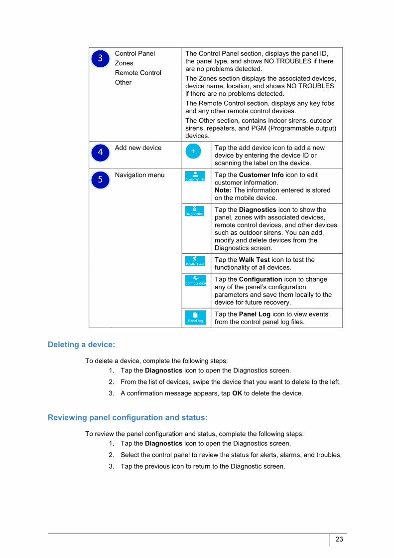
Control Panel Zones Remote Control Other
The Control Panel section, displays the panel ID, the panel type, and shows NO TROUBLES if there are no problems detected. The Zones section displays the associated devices, device name, location, and shows NO TROUBLES if there are no problems detected. The Remote Control section, displays any key fobs and any other remote control devices. The Other section, contains indoor sirens, outdoor sirens, repeaters, and PGM (Programmable output) devices.
Add new device
Tap the add device icon to add a new device by entering the device ID or scanning the label on the device.
Navigation menu Tap the Customer Info icon to edit customer information. Note: The information entered is stored on the mobile device.
Tap the Diagnostics icon to show the panel, zones with associated devices, remote control devices, and other devices such as outdoor sirens. You can add, modify and delete devices from the Diagnostics screen.
Tap the Walk Test icon to test the functionality of all devices.
Tap the Configuration icon to change any of the panel’s configuration parameters and save them locally to the device for future recovery.
Tap the Panel Log icon to view events from the control panel log files.
Deleting a device:
To delete a device, complete the following steps: 1. Tap the Diagnostics icon to open the Diagnostics screen.
2. From the list of devices, swipe the device that you want to delete to the left.
3. A confirmation message appears, tap OK to delete the device.
Reviewing panel configuration and status:
To review the panel configuration and status, complete the following steps: 1. Tap the Diagnostics icon to open the Diagnostics screen.
2. Select the control panel to review the status for alerts, alarms, and troubles.
3. Tap the previous icon to return to the Diagnostic screen.

24
Reviewing device configuration and status
To review a device configuration and status, complete the following steps: 1. Tap the Diagnostics icon to open the Diagnostics screen.
2. From the Zones, Remote Control or other list, select the device that you
want to view.
3. Review the following information:
Received Signal Strength Indicator (RSSI) information Alarms, alerts, and trouble information Configuration information
Note: If there is no device information displayed, you must download the
configuration information from the panel. See Retrieving the Panels configuration
parameters for details.
Editing device configuration
To edit the device configuration, complete the following steps: 1. Tap the Diagnostics icon to open the Diagnostics screen.
2. From the list of devices, select the device to edit.
3. Tap the pen icon in the upper-right corner of the screen to open the Edit
Current Configuration screen.
4. Select one or more parameters to change their values.
For some parameters tap the parameter to switch between values or select
from a list of new configuration items.
5. Tap the Save icon to commit the configuration changes to the panel. A
confirmation message appears, tap OK to commit the changes to the panel.
Note: The Save icon displays only after one or more changes are made. If
you close the screen without saving, an alert message appears stating that
all changes will be lost.
Save icon

25
Enrolling a new device
To enroll a new device, complete the following steps: 1. Tap the Diagnostics icon to open the Diagnostics screen.
2. Tap the add device (+) icon, to enroll a new device and take one of the
following actions:
To manually enter the panel ID, complete the following steps:
To scan the panel ID, complete the following steps:
3. The new device is pre-enrolled, place the device near to the panel and insert
the battery or press the tamper switch to enroll the device.
The following example shows the Diagnostics screen and the Device details screen after you pre-enroll a new key fob device.
Key fob device pre-enrolled Key fob device details screen
Pre-enroll icon

26
Radio Frequency testing
Test the communication from the alarm control panel to all devices enrolled on the panel. The Radio Frequency (RF) test reports if the communication was successful or not and shows the signal strength.
To activate an RF test for all devices enrolled on the panel, complete the following steps: Tap the Diagnostics icon to open the Diagnostics screen.
Tap the RF icon in the upper-right corner of the screen to start the test.
Review the test results.
Select a device to open the details view.
Note: The device details view, shows the Received Signal Strength Indicator
(RSSI) information with the date the test was carried out. In addition, the
current RF strength, average RF strength, the number of RF channels used
and if a repeater is used is displayed.
The following table shows the possible test results.
Icon Description of test results
RF strong signal
RF weak signal
RF transmission 1 way signal s
No communication
Test failed no results displayed

27
Walk Test screen
Activate each device enrolled on the panel to check that each detector is functioning correctly. The following figure shows the areas and icons on the Walk Test screen.
The following table describes the different areas and icons found on the Walk Test screen.
Area Icon Description
System activation The arrow icon is used to activate a Walk Test check for all devices.
The Panel ID and alarm panel state is displayed. The following alarm panel states are possible:
DISARM ARM AWAY ARM HOME ARMING AWAY ARMING HOME
The previous icon is used to disconnect from the panel and return to the panel’s screen.
Connection status The green bar indicates that the application is connected to the panel. When you first log on to the panel the bar is orange to indicate that the panel is online and changes to green when connected.

28
To start a walk test, complete the following steps: Tap the Walk Test icon to open the Walk test screen. This screen shows a
list of all devices and their locations.
Note: Ensure that connection status is green as it indicates that you are
connected to the panel.
Tap the right arrowhead icon to start the test.
Activate each device, for example open each door and window in the case of
a contact sensor, walk in front of each PIR detector or press the * button in
the case of a key fob.
As each device is tested the question mark icon is replaced by a green
check mark icon. For audio devices such as a siren, a sound is emitted for a
short period.
The walk test ends when all devices are activated or 10 minutes has elapsed
from the start time. A confirmation message appears stating that the test is
complete.
Review the test results, each device, location and status is displayed. See
the table above for a description of the device status.
Device and Status The location and name of the device is displayed. The status of a device can be testing, test complete or not tested.
Walk test has started, after you start the test all devices display this icon as each device must be activated.
Device is activated and tested.
Device was not activated.
Navigation menu Tap the Customer Info icon to edit customer information. Note: The information entered is stored on the mobile device.
Tap the Diagnostics icon to show the panel, zones with associated devices, remote control devices, and other devices such as outdoor siren. You can add, modify and delete devices from the Diagnostics screen.
Tap the Walk Test icon to test the functionality of all devices.
Tap the Configuration icon to change any of the panel’s configuration parameters and save them locally to the device for future recovery.
Tap the Panel Log icon to view events from the control panel log files.

29
Configuration screen
You can view and edit panel configuration parameters and go back to a previous configuration version. The following figure shows the areas and icons on the Walk Test screen.
The following table describes the different areas and icons found on the Configuration screen.
Area Icon Description
System activation The Panel ID and alarm panel state is displayed. The following alarm panel states are possible:
DISARM ARM AWAY ARM HOME ARMING AWAY ARMING HOME
The previous icon is used to disconnect from the panel and return to the panel’s screen.
Connection status The green bar indicates that the application is connected to the panel. When you first log on to the panel the bar is orange to indicate that the panel is online and changes to green when connected.

30
Retrieving the panels configuration parameters
To retrieve the configuration parameters of a panel, complete the following steps: Tap the Configuration icon to open the Configuration screen.
Tap the Circular arrow icon to retrieve the panel’s configuration.
Note: If configuration data already exists, the date and time that the
configuration was uploaded is displayed. Any changes that were made to the
configuration since that date are not reflected in the configuration.
The configuration data is stored on the PowerManage server, see Specifying
the time to retain configuration parameters for details.
Archiving the configuration parameters
To save and archive the configuration parameters, complete the following steps: Tap the Configuration icon to open the Configuration screen.
Tap the disc icon to save the configuration to the mobile device.
Enter the name and select ARCHIVE.
Tip: Archive the panel’s configuration parameters before you change the current
configuration. This archive is saved to your mobile devices memory and can be
restored to the panel if required.
Current configuration The date and time the configuration was uploaded is displayed. If “Tap to load” is displayed, you must first retrieve the information.
Tap the Disc icon to save the configuration locally to the mobile device.
Tap the Circular arrow icon to retrieve the panel’s configuration.
Navigation menu Tap the Customer Info icon to edit customer information. Note: The information entered is stored on the mobile device.
Tap the Diagnostics icon to show the panel, zones with associated devices, remote control devices, and other devices such as outdoor siren. You can add, modify and delete devices from the Diagnostics screen.
Tap the Walk Test icon to test the functionality of all devices.
Tap the Configuration icon to change any of the panel’s configuration parameters and save them locally to the device for future recovery.
Tap the Panel Log icon to view events from the control panel log files.

31
Deleting an archived configuration
To delete an archived configuration, complete the following steps: Tap the Configuration icon to open the Configuration screen.
Swipe the archived configuration to the left to delete.
Viewing and changing configuration parameters
To view and change the parameters, complete the following steps: Tap the Configuration icon to open the Configuration screen.
Select the current configuration to open the Edit Current Configuration
screen.
To change a parameter, take one of the following actions:
To modify the Partition set parameter, select the parameter to switch between the value enable or disable. To modify other parameters, take the following actions:
On the Edit Current Configuration screen, tap the Save icon to commit the
configuration changes to the panel. A confirmation message appears, tap
OK to commit the changes to the panel.
Note: The Save icon only displays after one or more changes are made. If
you close the screen without saving, an alert message appears stating that
all change will be lost.
The following example shows the Edit Configuration screen and certain
parameters in the zones definition and communication settings are changed.
Save icon
Parameter sections with changes in Zones and
Communication settings

32
Specifying the time to retain configuration parameters
The number of days that a configuration is retained before you must retrieve the latest configuration from a panel is specified in the PowerManage MMI console. To specify the retention time, complete the following steps:
Log on to the PowerManage MMI console.
On the MMI console menu, go to Settings > Application configuration > Resolve > Events & processing age to display the Events and Processing
maximum age page.
Enter the number of days to retain the configuration before it is deleted in the
Processor age (days) field. The default value is 30. After 30 days, you must
retrieve the current configuration from the panel.

33
Panel Log screen
The panel log screen shows the events of the control panel and the associated devices. The following figure shows the areas and icons on the Diagnostics screen.
Area Icon Description
System activation The refresh button is used to upload the log file from the control panel.
The Panel ID and alarm panel state is displayed. The following alarm panel states are possible:
DISARM ARM AWAY ARM HOME ARMING AWAY ARMING HOME
The previous icon is used to disconnect from the panel and return to the panel’s screen.
34
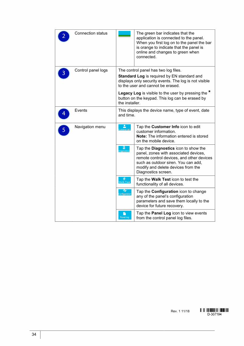
Connection status
The green bar indicates that the application is connected to the panel. When you first log on to the panel the bar is orange to indicate that the panel is online and changes to green when connected.
Control panel logs The control panel has two log files. Standard Log is required by EN standard and displays only security events. The log is not visible to the user and cannot be erased.
Legacy Log is visible to the user by pressing the * button on the keypad. This log can be erased by the installer.
Events This displays the device name, type of event, date and time.
Navigation menu Tap the Customer Info icon to edit customer information. Note: The information entered is stored on the mobile device.
Tap the Diagnostics icon to show the panel, zones with associated devices, remote control devices, and other devices such as outdoor siren. You can add, modify and delete devices from the Diagnostics screen.
Tap the Walk Test icon to test the functionality of all devices.
Tap the Configuration icon to change any of the panel’s configuration parameters and save them locally to the device for future recovery.
Tap the Panel Log icon to view events from the control panel log files.
Rev. 1 11/18