©alex doboli chapter 3: hardware and software subsystems of mixed-signal architectures (part ii)...
TRANSCRIPT

©Alex Doboli
Chapter 3:Hardware and Software Subsystems
of Mixed-Signal Architectures(Part II)
Alex Doboli, Ph.D.
Department of Electrical and Computer Engineering
State University of New York at Stony Brook
Email:[email protected]

©Alex Doboli
Tachometer ISR
• Tachometer ISR used in PSoC Express
• Specification:– Fan speed is measured through 3 pulses produced by the fan– Time distance between consecutive pulses is used to find
RPMs – Response to fan inputs:
• Decouple fan from PWM and drive at full speed• Let fan speed stabilize• Measure time between consecutive pulses• Reconnect fan to PWM
– The 3 pulses must be received within 3 sec, otherwise this represents an abnormal functioning that is handled by the ISR
– Consecutive fan speed readings should be separated by at least 4 sec (otherwise readings are incorrect)
– ISR should handle multiple fans

©Alex Doboli
• Functionality is even-driven & corresponds to FSM• Events are the tachometer pulses• FSM states implement the controller response
• Interrupt-based solution vs. polling• Reduced overhead (Estimate the overhead)• How are interrupts generated? Tachometer pulses are not
interrupts
• Real-time constraints• 3 pulses within 3 sec (HW vs. SW solution)• Two consecutive readings separated by at least 4 sec (HW
vs. SW solution)
• Data structure for handling multiple fans• State information tables
Tachometer ISR

©Alex Doboli
Tachometer interfacing

©Alex Doboli
Specification of the tachometer ISR
Introduces delay
of 4 sec
• abnormal• switch to next• 4 sec delay

©Alex Doboli
Pseudocode for FSM1 ISR

©Alex Doboli
Pseudocode for FSM2 ISR

©Alex Doboli
Multiple tachometers

©Alex Doboli
Data structures for handling multiple tachometers

©Alex Doboli
Tachometer ISR implementation

©Alex Doboli
• Specification: – Event-driven, FSM– Two FSMs used: one for the ISR functionality and one
implements the timing requirement for the functionality
• Interrupt driven implementation – Reduces CPU idle times (overhead)– Interrupts are generated by programmable digital block (DCB02)
• Data structure (table) for multiple tachometers (fans)– Sharing of design for multiple tachometers
• Hardware & software implementation– FSM in software– Interrupt generation & time measurement in hardware– Maximum time constraint in hardware (block DCB03)
ISR implementation

©Alex Doboli
• Programmable General I/O Ports (GIOPs):– I or O ports– Connected to CPU, digital resources, programmable
analog blocks– Driving capabilities– Can originate interrupt signals
• Pin block– Pin (chip package), input buffer, 1-bit register, output
drivers, configuration logic
• 8 driving modes:– Resistive pull down, strong drive, high impedance drive,
resistive pull up, open drain-drives high, slow strong, high impedance, open drain-drives low
Global I/O ports

©Alex Doboli
Port driving modes (output)
©Alex Doboli
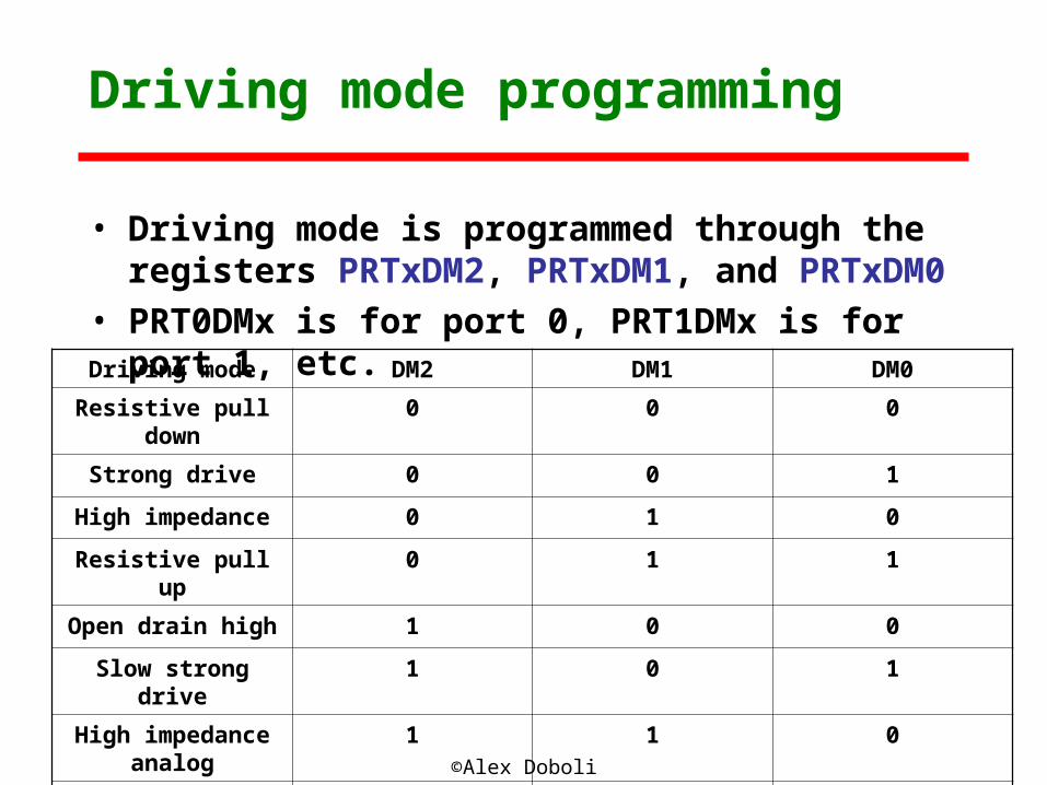
• Driving mode is programmed through the registers PRTxDM2, PRTxDM1, and PRTxDM0
• PRT0DMx is for port 0, PRT1DMx is for port 1, etc.
Driving mode programming
Driving mode DM2 DM1 DM0
Resistive pull down 0 0 0
Strong drive 0 0 1
High impedance 0 1 0
Resistive pull up 0 1 1
Open drain high 1 0 0
Slow strong drive 1 0 1
High impedance analog
1 1 0
Open drain low 1 1 1
©Alex Doboli
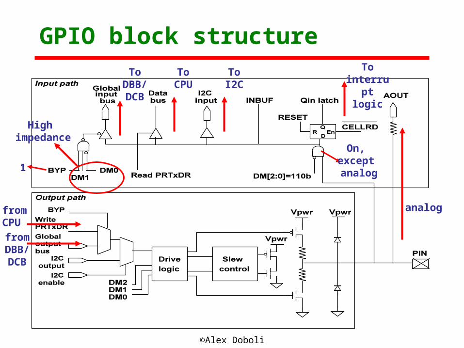
GPIO block structure
analog
On, except analog
ToCPU
ToDBB/DCB
ToI2C
1
from CPU
fromDBB/DCB
High impedance
To interrupt
logic
©Alex Doboli
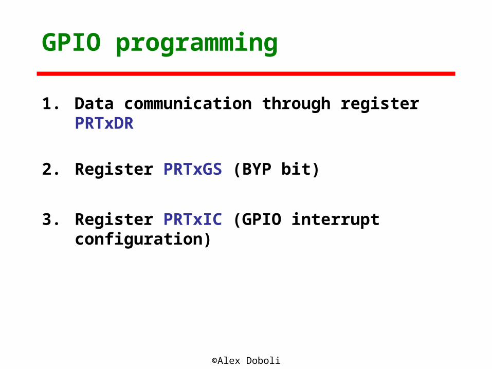
GPIO programming
1. Data communication through register PRTxDR
2. Register PRTxGS (BYP bit)
3. Register PRTxIC (GPIO interrupt configuration)