alfa laval mbux 214
TRANSCRIPT

Alfa Laval MBUX 214 centrifuge is used for recovery of micro-organisms and cell debris in high density fermentations.
ApplicationThe solids discharging nozzle centrifuge type MBUX 214 is designed specially for separation of microorganisms from high density fermentation broths.
The centrifuge is used to separate, wash and concentrate microorganisms with normal particle size in the range 1 - 5 μm. The content of the suspended solids in the feed is normally in the range 2 - 7,5% DS.
Design featuresWith the patented Alfa Laval self regulating vortex nozzles the concentration of discharged solids phase can be kept at a high and even level irrespective of fluctuations in the feed flow or feed concentration. The centrifuge can thus be operated closer to the clogging point without increasing the risk of clog-ging.
The disc inlet ensures a lenient acceleration of shear sensitive microorganisms.
The light and heavy phases are both discharged under pres-sure which prevents foaming and simplifies installation by eliminating pump systems and improves hygiene.
Solids pockets in the bowl guide the solids to the concentrate tubes, preventing accumulation of firmly packed solids and making separation and CIP easier and more effective.
Frame hood and solids receptacles are jacketed for circula-tion of cooling water, which also reduce the noise level. Frame hood and solids receptables are fitted with spray nozzles for washing the outside of the bowl.
The Control Panel (optional) handles the control and supervi-sion of the MBUX 214 centrifuge including a cleaning-in-place (CIP) mode.
Solids discharging nozzle centrifuge
Alfa Laval MBUX 214
Alfa Laval MBUX 214
Standard design All liquid-wetted parts are made in high-grade stainless steel except the rubber gaskets (EPDM). The bearings are lubri-cated by an external lubrication circuit. The vertical driving device and bowl spindle is designed as an easily serviced unit. The entire assembly lifts out in one piece. The centrifuge is equipped with sensors for monitoring of bowl speed and vibration level. Standard motor 55/75/90 kW for frequency converter drive, or control torque motor 75/90 kW.
Архангельск (8182)63-90-72 Астана (7172)727-132 Астрахань (8512)99-46-04 Барнаул (3852)73-04-60 Белгород (4722)40-23-64 Брянск (4832)59-03-52 Владивосток (423)249-28-31 Волгоград (844)278-03-48 Вологда (8172)26-41-59 Воронеж (473)204-51-73 Екатеринбург (343)384-55-89 Иваново (4932)77-34-06
Ижевск (3412)26-03-58 Иркутск (395)279-98-46 Казань (843)206-01-48 Калининград (4012)72-03-81 Калуга (4842)92-23-67 Кемерово (3842)65-04-62 Киров (8332)68-02-04 Краснодар (861)203-40-90 Красноярск (391)204-63-61 Курск (4712)77-13-04 Липецк (4742)52-20-81 Киргизия (996)312-96-26-47
Магнитогорск (3519)55-03-13 Москва (495)268-04-70 Мурманск (8152)59-64-93 Набережные Челны (8552)20-53-41 Нижний Новгород (831)429-08-12 Новокузнецк (3843)20-46-81 Новосибирск (383)227-86-73 Омск (3812)21-46-40 Орел (4862)44-53-42 Оренбург (3532)37-68-04 Пенза (8412)22-31-16 Казахстан (772)734-952-31
Пермь (342)205-81-47 Ростов-на-Дону (863)308-18-15 Рязань (4912)46-61-64 Самара (846)206-03-16 Санкт-Петербург (812)309-46-40 Саратов (845)249-38-78 Севастополь (8692)22-31-93 Симферополь (3652)67-13-56 Смоленск (4812)29-41-54 Сочи (862)225-72-31 Ставрополь (8652)20-65-13 Таджикистан (992)427-82-92-69
Сургут (3462)77-98-35 Тверь (4822)63-31-35 Томск (3822)98-41-53 Тула (4872)74-02-29 Тюмень (3452)66-21-18 Ульяновск (8422)24-23-59 Уфа (347)229-48-12 Хабаровск (4212)92-98-04 Челябинск (351)202-03-61 Череповец (8202)49-02-64 Ярославль (4852)69-52-93
https://alaval.nt-rt.ru || [email protected]
ʉɽʇɸʈɸʎʀʆʅʅʆɽ ʆɹʆʈʋɼʆɺɸʅʀɽ

Technical dataUtilities consumptionElectric power Max 90 kW 1)
Operating air 25 NI /discharge 2)
Safety water 10 - 30 m3/h 3)
Flushing liquid 0 - 15 l/discharge 4)
Cooling liquid 500 l/h 5)
1) Actual consumption depends on exact throughput capacity,centrifugate & concentrate flow rate and applied back pressure.
2) Instrument quality, 500-600 kPa. Actual consumption dependson CIP-discharge frequency.
3) The bowl should be filled with liquid at start, stop and normaloperation. In case process liquid is not available, safety watershould be used. Minimum flow shall be 10% above nozzle flow.
4) 100 - 600 kPa, 300 kPa suggested. Momentary flow rate atsuggested pressure up to 800 l/h. Used only during CIP.
5) Data valid for 50 kPa. Max. pressure 100 kPa.
Technical specificationMax. throughput capacity 30 m3/h 1)
Max. nozzle flow 22 m3/h 2)
Feed temperature range 0 - 100 °C
Feed inlet pressure required Max. 15 kPa 3)
Centrifugate outlet pressure available 100 kPa 4)
Concentrate outlet pressure available 550 kPa
Installed motor power 55/75/90 kW
Noise level 78,5 dB(A)1) Actual consumption depends on exact throughput capacity,
centrifugate & concentrate flowrate and applied back pressure.
2) Wet solids.
3) Data valid for water at feed flowrates up to 30 m3/h and outletpressure 400 kPa.
4) Data valid for a centrifugate flowrate flow of 26 m3/h.
Operating principleThe feed containing the liquid and the solids is introduced to the rotating centrifuge bowl (fig 1) from the top via a stationary inlet pipe (1), and is accelerated in a distributor (2) with disc inlet before entering the disc stack (3). It is between the discs that the separation takes place.
The liquid phase moves through the disc stack towards the centre of the bowl, from where it is pumped out under pres-sure by means of a built-in paring disc (4). The heavy solids phase is moved outwards by centrifugal force to the solids pockets at the bowl periphery and from there through concen-trate tubes (5) and internal vortex nozzles (6) into the paring tube chamber, where the concentrate is skimmed off by the paring tube (7) and discharged under pressure.
The bowl can be opened intermittently during production and/or the cleaning cycle for ejections of solids while the machine continues to run at full speed. The pneumatically (8) controlled valve slide (9) under the bowl bottom opens the discharge valves (10) momentarily, permitting the ejections of solids.
Fig. 1 Typical bowl drawing for a vortex nozzle centrifuge. Drawing details do not necessarily correspond to the centrifuge described.
Shipping data (approximate)Centrifuge weight, without motor 2785 kg (6140 lbs)
Motor weight 420-725 kg (926-1598 lbs)
Gross weight, max 3800 kg (8378 lbs)
Volume 8.0 m3
Dimensions
1254 mm (4 ft 1 3/8 in) 2189 mm (7 ft 2 3/16 in)
min
. 318
5 m
m (1
0 ft
5 3 /
8 in
)

Nozzle separator for hygienic, pressurised recovery of microorganisms
MBUX 420
The Alfa Laval centrifuges for recovery of yeast and other microorganisms take advantage of the fact that the slurry of concentrated solids is pseudo-plastic and flows easily in the bowl against the centrifugal force. This means that the recov-ered solids can be obtained with a low demand on energy in a closed system under pressure. Therefore, the hygienic conditions are very good, further improved by a full-speed CIP procedure. The MBUX 420 has a bowl body in Super Duplex stainless steel, for added strength and corrosion resistance.
Applications The solids discharging nozzle centrifuge type MBUX 420 is designed for separation of micro-organisms from fermentation broths, e.g. in chemical and pharmaceutical industries, and for yeast extract production.
Special features With the patented Alfa Laval self regulating vortex nozzles the concentration of discharged solids phase can be kept at a high and even level irrespective of fluctuations in the feed flow or feed concentration. The centrifuge can thus be operated closer to the clogging point without increasing the risk of clog-ging. The light and heavy phase are both discharged under pressure which prevents foaming and simplifies installation by eliminating pump systems and improves the hygiene. Solids pockets in the bowl guide the solids to the concentrate tubes, preventing accumulation of firmly packed solids and making separation and Cleaning In Place (CIP) easier and more effec-tive. Automated CIP at full speed. Frame hood and solids receptacle are jacketed for circulation of cooling water, which also reduce the noise level. Frame hood is fitted with a spray nozzle for washing the outside of the bowl. A rotating liquid seal below the bowl seals off the bowl casing from the drive system.
MBUX 420
Standard design The MBUX 420 has all liquid-wetted parts in high-grade stain-less steel and rubber sealings food approved EPDM or nitrile rubber. Connections for inlet, centrifugate and concentrate are hygienic screw couplings. The separator is equipped with speed and vibration sensors. The anchoring feet are equipped with vibration dampers. The MBUX 420 is driven via a belt by a flange-mounted controlled torque motor. The separator is delivered with the motor pre-mounted at the factory so there is no need for alignment on site.

Operating principlesSeparation takes place in the disc type bowl which is equipped with concentrate tubes and vortex nozzles. The heavy solids phase is moved outwards by the centrifugal force in to the solids pockets at the bowl periphery and from there through concentrate tubes (1) and internal vortex noz-zles (2) into the paring tube chamber, where the concentrate is skimmed off by the paring tube (3) and discharged under pressure. The clarified liquid phase is displaced towards to the centre through the disc stack (4). This phase is then dis-charged under pressure by means of a built in paring disc (5). The bowl can be opened intermittently during production and/or the cleaning cycle for ejections of solids while the machine continues to run at full speed. The hydraulic (6) controlled valve slide (7) under the bowl bottom opens the discharge valves (8) momentarily, permitting the ejections of solids.
3
5
4
1
8
7
6 2
Typical bowl drawing for a vortex nozzle centrifuge. Drawing details do not necessarily correspond to the centrifuge described.
Utilities consumption
Electric power, max 100 kW 1)
Operating and sealing water 150–300 dm3/h 2)
Safety water 2–50 m3/h 3)
Flushing liquid, at 100 kPa 600 l/h 4)
1) Actual consumption depends mainly on throughput capacity, centrifugate &concentrate flowrate and applied back pressure.
2) Actual consumption depends on CIP-discharge frequency3) Depending on solids-handling capacity 4) Only during CIP
Dimensions
Shipping data (approximate)
Centrifuge with bowl and motor 3,700 kg
Gross weight 4,100 kg
Volume 7.6 m3
Technical specification
Throughput capacity max. 100 m3/h 1)
Solids handling capacity max. 45 m3/h
Feed temperature range 0–100 0C
Feed inlet pressure required max. 50 kPa
Centrifugate outlet pressure max. 600 kPa
Bowl volume 70 l
Concentrate outlet pressure, recommended 300 kPa
Bowl speed, synchronous 3,740 rpm
Motor power 90/135 kW
Motor speed, synchronous 50/60 Hz 1,500/1,800 rpm
Starting time 7–11 mins
Stopping time with brake 25–30 mins
Sound pressure 92 dB(A) 2)
Over head hoist lifting capacity 3,500 kg1) Actual throughput capacity depends on amount and type of solids in the
feed, temperature, viscosity and required degree of clarification2 ) According to EN ISO 4871
Material data
Bowl body s.s 1.4501 UNS S32760
Bowl hood and lock ring s.s 1.4462 UNS S31803
Frame lower part grey cast iron
Frame upper part and hood s.s 1.4401 UNS 31600
Gaskets and O-rings Nitrile rubber or food grade EPDM

Solids-discharging Nozzle Centrifuge MBUX 510T-34C
ApplicationsThe solid-discharging nozzle centrifuge type MBUX 510
is designed specially for separation of minute micro-organism and cell debris from such organisms in processeswhere sterilization or containment is not required.
The centrifuge is used to separate and concentrate micro-organisms or cell debris with normal particle size in therange 0,1 - 3 µm. The content of suspended solids in thefeed varies but is normally in the range 0,5 - 4% DS. In celldebris type of duties normally a significant amount of solidsare dissolved in the process liquid.
Working principleThe feed containing the liquid and the solids is
introduced to the rotating centrifuge bowl (fig 2) from thetop via a stationary inlet pipe (1), and is accelerated in adistributor (2) before entering the disc stack (3). It isbetween the discs that the separation takes place.
The liquid phase moves through the disc stack towardsthe centre of the bowl, from where it is pumped out underpressure by means of a built-in paring disc (4).
The heavy solids phase is moved outwards bycentrifugal force to the solids pockets at the bowl peripheryand from there through concentrate tubes (5) and internalvortex nozzles (6) into the paring tube chamber, where theconcentrate is skimmed off by the paring tube (7) anddischarged under pressure.
The bowl can be opened intermittently during productionand/or the cleaning cycle for ejections of solids while themachine continues to run at full speed.
The pneumatically (8) controlled valve slide (9) underthe bowl bottom opens the discharge valves (10)momentarily, permitting the ejections of solids.
Special featuresWith the patented Alfa Laval self regulating vortex
nozzles the concentration of discharged solids phase can bekept at a high and even level irrespective of fluctuations inthe feed flow or feed concentration. The centrifuge can thusbe operated closer to the clogging point without increasingthe risk of clogging.
The light and heavy phases are both discharged underpressure which prevents foaming and simplifies installationby eliminating pump systems and improves hygiene.
Solids pockets in the bowl guide the solids to theconcentrate tubes, preventing accumulation of firmly packedsolids and making separation and CIP easier and moreeffective.
Frame hood, solids receptacle and large cyclone arejacketed for circulation of cooling water, which also reducethe noise level. Frame hood and large cyclone are fitted withspray nozzles for washing the outside of the bowl and theinterior of the large cyclone.
The Control Panel (optional) handles the control andsupervision of the MBUX 510 centrifuge including acleaning in-place (CIP) mode. Necessary control valves areoptional.
Conversion from the solids-discharging vortex nozzlestype, to solids-ejecting type is possible.
Fig 1. MBUX 510T-34C (large cyclone).
Fig 2. Typical bowl drawing for a Vortex nozzle centrifuge. Drawingdetails do not necessarily correspond to the centrifuge described.

PD88115901Rev. 3 / 01 03
Alfa Laval Tumba ABProcess Technology Division
S-147 80 TUMBA, SWEDEN
Standard designAll liquid-wetted parts are made in high-grade stainless
steel except the rubber gaskets (EPDM or nitrile).A special controlled-torque motor eliminates the need
for a clutch between the motor and the centrifuge.The gear is splash lubricated without any need for an
external lubrication circuit. The vertical driving device andbowl spindle is designed as an easily serviced unit. Theentire assembly lifts out in one piece.
The centrifuge is equipped with sensors for monitoringof bowl speed and vibration level.
Technical specification
Max. throughput capacity 10 m3/h 1)
Max. solids-handling capacity 3 m3/h 2)
Feed temperature range 0-100 °CFeed inlet pressure required -10 kPa 3)
Centrifugate outlet pressureavailable
Up to 600 kPa
Concentrate outlet pressureavailable
Up to 600 kPa (300kPa normal)
Installed motor power 37 kWNoise level 82 dB(A)
1) Actual throughput capacity depends on amount and type ofsolids in the feed, temperature, viscosity and required degree ofclarification.
2) Wet solids.3) Data valid for water at feed flowrates up to 10 m3/h.
Utilities consumption
Electric power 20-30 kW 1)
Operating air 30 Nl/discharge2)
Safety water 0.2 - 2 m3/h 3)
Flushing liquid; above bowl, incyclone & air compensation pipe
0 - 25 l/discharge4)
Cooling liquid, frame 0 - 1400 l/h5)
Cooling liquid, cyclone max. 2400 l/h6)
1) Actual consumption depends on exact throughput capacity,centrifugate & concentrate flowrate and applied back pressure.
2) Instrument quality, 500 - 600 kPa. Actual consumptiondepends on CIP-discharge frequency.
3) The bowl should be filled with liquid at start, stop and normaloperation. In case process liquid is not available, safety watershould be used. Minimum flow shall be 10% above nozzleflow.
4) 100 - 600 kPa, 300 kPa suggested. Momentary flowrate atsuggested pressure up to 1000 l/h.
5) Max. pressure 100 kPa. Flowrate at 30 kPa 700 l/h.6) Max. Pressure 100 kPa. Flowrate at 30 kPa 800 l/h.
(Valid for large cyclone only)
Shipping data (approximate)
Centrifuge with bowl and motor
Net weight: 1500 kgGross weight: 1800 kgVolume: 4.0 m3
Main dimensions
OptionsThe centrifuge can be equipped with a gauge switch to
prevent the motor from being started unless the centrifugetop part has been properly mounted.
The centrifuge is available with two alternative discstacks with different caulk thickness.
Vortex outlet washer and chambers in stainless steelinstead of tungsten carbide.
Small cyclone without cooling jacket.
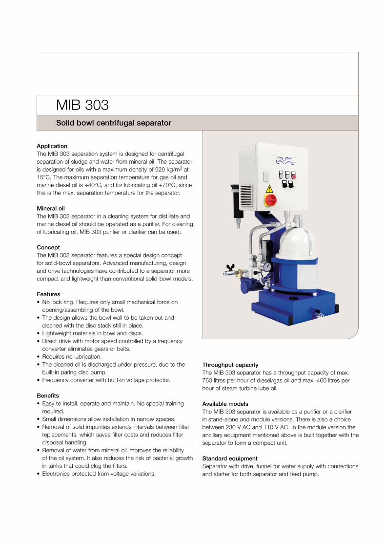
ApplicationThe MIB 303 separation system is designed for centrifugalseparation of sludge and water from mineral oil. The separator is designed for oils with a maximum density of 920 kg/m3 at 15°C. The maximum separation temperature for gas oil and marine diesel oil is +40°C, and for lubricating oil +70°C, since this is the max. separation temperature for the separator.
Mineral oilThe MIB 303 separator in a cleaning system for distillate andmarine diesel oil should be operated as a purifier. For cleaningof lubricating oil, MIB 303 purifier or clarifier can be used.
ConceptThe MIB 303 separator features a special design concept for solid-bowl separators. Advanced manufacturing, design and drive technologies have contributed to a separator more compact and lightweight than conventional solid-bowl models .
Features• No lock ring. Requires only small mechanical force on
opening/assembling of the bowl.• The design allows the bowl wall to be taken out and
cleaned with the disc stack still in place.• Lightweight materials in bowl and discs.• Direct drive with motor speed controlled by a frequency
converter eliminates gears or belts.• Requires no lubrication.• The cleaned oil is discharged under pressure, due to the
built-in paring disc pump.• Frequency converter with built-in voltage protector.
Benefits• Easy to install, operate and maintain. No special training
required.• Small dimensions allow installation in narrow spaces.• Removal of solid impurities extends intervals between filter
replacements, which saves filter costs and reduces filterdisposal handling.
• Removal of water from mineral oil improves the reliabilityof the oil system . It also reduces the risk of bacterial growthin tanks that could clog the filters.
• Electronics protected from voltage variations.
Throughput capacityThe MIB 303 separator has a throughput capacity of max. 760 litres per hour of diesel/gas oil and max. 460 litres per hour of steam turbine lube oil.
Available modelsThe MIB 303 separator is available as a purifier or a clarifier in stand-alone and module versions. There is also a choice between 230 V AC and 110 V AC. In the module version the ancillary equipment mentioned above is built together with the separator to form a compact unit.
Standard equipmentSeparator with drive, funnel for water supply with connections and starter for both separator and feed pump.
MIB 303Solid bowl centrifugal separator

115
245
610
1020
510370
Ancillary equipmentNecessary for operation are: feed pump, collecting tank with water seal alarm, strainer, valves and fittings.
Optional equipmentThe MIB 303 module is also available in the mobile version on the trolley.
Power consumption700 W ±10%.
Weight of module 68 kg (81 kg for the trolley version).
Purifier operation Separation takes place in the rotating solid-wall bowl. The uncleaned oil is fed into the bowl where the cen-trifugal force makes water and solid particles move out towards the periphery of the bowl, while the clean oil flows inwards.
To establish a water seal during start-up of the separator, water is added to the bowl before the oil feed is started. The water collects in the water seal which drains into the water channel below the bowl.
The solids accumulate on the bowl wall and are removed periodically by hand.
The cleaned oil flows towards the centre of the bowl and up to the paring disc. Since the oil is rotating , the stationary paring disc acts as a pump which forces the oil out through the outlet under pressure.
Clarifier operation In clarifier mode the oil normally does not contain any free water. The separation principle is similar to that of the purifier, although there is no water seal and no water outlet in the bowl and the water handling capacity is limited.
Technical documentation Complete information and documentation is provided in the instruction book accompanying each MIB 303 separator.
After sales support Replacement part kits for preventive maintenance at one and two years intervals are available.
Dimensions, mm
Module version
Mobile module version (trolley version)
Stand-alone version
Functional principle of the MIB 303 purifier.
Functional principle of the MIB 303 clarifier.
Oil inlet
Clean oil outlet
Bowl
Solid space
Water outlet
Oil inlet
Clean oil outlet
Bowl
Solid space
280
28045
3
718
546675
17530
5
650
380
1188

Alfa Laval MIB 503 ModuleA compact separator module for marine & diesel applications
Introduction
In marine and diesel industry, customers struggle with low-quality fuels that have high content in particles and water.Operating on such fuels reduces the efficiency and the lifetimeof the engine while increases the risk of repair costs.
The MIB 503 Module is a complete separation solution fromAlfa Laval that improves the reliability of the oil system andprotects the main engine from serious wear and damages.
Application
• Distillate oil• Marine diesel oil• Lubricating oil
Benefits
• Easy to install and start up• Easy to operate and maintain• High separation efficiency• Robust and reliable design• Small footprint• Low power consumption
Design
The module is available in a gas oil and a lube oilconfiguration.
The gas oil configuration consists of the separator, the controlcabinet, the pump, the flexible hoses and the alarm sensors.All of the components are mounted in an optimally designedframe that can fit even the smallest engine rooms.
The MIB 503 separator consists of a solids-retaining bowlwhich can operate both as a purifier and a clarifier. Its uniquedrive technology is based on an electric motor mounteddirectly to the bowl, controlled by a frequency converterlocated in the control cabinet.
The pump installed on the module is a positive displacementpump with constant flow and is connected to the separatorthrough flexible hoses.
To secure the correct operation of the separator, a pressuresensor and a level sensor are installed on the module. Allfunctions and alarms are being handled from the controlcabinet which has been designed for simplicity and ease ofuse.
In lube oil configuration, the oil must reach the righttemperature before the separation process starts. Toaccomplish that, a heater, a three way valve and atemperature sensor are included in the module.
Scope of supply
• MIB 503 Separator• Pump• Flexible hoses• Control cabinet• Sensors• Frame• Three way valve (only for lube oil)• Heater (only for lube oil)
Options
• Wheel set• Drip tray• Emergency stop box• Trolley (only for gas oil)

Working principle
In gas oil application, the fuel oil is being transferred directlyfrom the pump to the separator. In lube oil application, aheater and a three way valve are installed between the pumpand the separator. The three way valve is being used to runthe oil on recirculation between the sump and the heater untilthe correct separation temperature is reached.
The separator starts up. When the separator reaches fullspeed, water is added to establish the appropriate water seal(applicable only for purifier setup). Subsequently, the pumpstarts up and oil is fed to the separator.
The separation process takes place within the bowl. Due tothe centrifugal forces, oil, water and particles are beingseparated based on their specific gravity. The heavy phases,water and particles, are moving to the periphery of the bowlwhile the light phase, oil, is moving towards the center of thebowl.
Water is being drained automatically to the collecting tank ofthe module. The separated particles need to be cleanedperiodically by hand. The clean oil is being pumped by aparing disc out of the separator and from there to the dailyservice fuel tank or the lube oil sump.
A pressure sensor is installed in the oil outlet after theseparator. The pressure sensor triggers an alarm duringseparation if the water seal interface is lost.
A level sensor is installed on the collecting tank of the module.The level sensor triggers an alarm if the separator overflows.
In lube oil configuration, a temperature sensor is installedbefore the separator. The sensor triggers an alarm when lubeoil temperature drops below 60°C.
All the sensors are connected to the pump which will stopautomatically if there is an alarm. In that case, the crew isinformed by the alarm lamp in the control cabinet of themodule.
3
5
1
11
13
12
2
8
9
4
76
10T
14
General flow chart of a separator system. The detail may differ slightlybetween different systems.
1. Feed inlet2. Pump3. Water for water seal (only for purifier)4. Separator5. Clean oil outlet6. Collecting tank7. Drain8. Control cabinet9. Emergency stop box (optional)
10. Heater (only for lube oil)11. Heating media inlet (only for lube oil)12. Heating media outlet (only for lube oil)13. Three way valve (only for lube oil)14. Oil heat up recirculation (only for lube oil)

Technical data Performance data
Feed capacities:
- Gas oil (1,5 – 6 cSt/40°C) Max. 1250 l/h
- Marine diesel oil (13 cSt/40°C) Max. 1000 l/h
- Lube oil (Trunk/95°C) Max. 300 l/h
Power consumption 0,7 kW (0,93 HP)
Feed temperature Max. 95°C
Connections
Feed inlet G 3/4 inch
Clean oil outlet G 1/2 inch
Drain G 1/2 inch
Heat media inlet G 3/4 inch
Heat media outlet G 3/4 inch
Material data
Separator frame Surface coated aluminum
Separator bowlSurface coated aluminum. High-gradepolymer composite
Module frame Structural steel
Gaskets and O-rings Fluorocarbon rubber (Viton®)
Weights (approximate)
Separator weight incl. bowl andmotor
18 kg (39,7 lbs)
Bowl weight 4 kg (8,8 lbs)
Gas oil module weight (net/gross) 72/102 kg (159/225 lbs)
Lube oil module weight (net/gross) 82/114 kg (181/251 lbs)
Volume 0,58 m3
Dimensional drawing
Gas oil application
W3
W2
H1
W1
Lube oil application
H1
W4
W2
W3
W1
Dimensions
H1 1026 mm (3 ft 4 3/8 inch)
W1 640 mm (2 ft 1 3/16 inch)
W2 400 mm (1 ft 3 3/4 inch)
W3 525 mm (1 ft 8 11/16 inch)
W4 760 mm (2 ft 5 15/16 inch)

Nozzle centrifuge
CH-38 GOF Separator
Alfa Laval separators for the starch industry are available in many different sizes and configurations, each one designed and adapted for dealing with the widely varying separation tasks required. The Merco CH-38 GOF is a dedicated starch centrifuge, designed for several applications in the maize wet milling process.
ApplicationsThe CH-38 GOF is a nozzle centrifuge designed for continu-ous discharge of solids. It is used for classification of solids according to size, dewatering and washing of solids, and for clarification of liquids containing relatively high concentrations of solids. The machine is Alfa Laval’s largest nozzle centrifuge for the maize starch industry. It is related to the widely used CH-36 but has a higher capacity and a larger bowl. It has a lower power consumption and is easier to assemble and disassem-ble. The CH-38 GOF is used for processes that include primary separation, gluten thickening, millstream thickening and mid-dling separation. Other common applications include wash-ing and concentration of solids in the production of industrial minerals and chemicals.
Standard designThe centrifuge is equipped with sensors for monitoring bowl speed, vibration, temperature and oil pressure. Thirty periph-eral nozzles are directed at a small angle to the tangent in order to recover energy from the material being discharged.
Special featuresThe CH-38 employs a special recirculation system that provides highly efficient separation. Solids can be recircu-lated to the nozzles at the same time as wash water is being recirculated. Working with the underflow draw-off valve, the return flow system provides a unique means of controlling the separation process. It allows the operator to control and optimise the separation process – by determining how much underflow is to be removed, how much is to be recycled back to the rotor and how much wash water is to be added. This makes it possible to use nozzles with a large diameter, which act as buffers to even out variations in feed concentration and to prevent blockages. The machine thus becomes more versatile, and can be easily adapted to changes in procedure.
Merco CH-38 GOF with motor
The machine also features a built-in hydraulic hoist that elimi-nates the need for an external lifting device, and thus reduces the downtime required to service the centrifuge.
Basic equipmentThe centrifuge is equipped with a motor, a self-cleaning strainer for the feed, speed and vibration sensors, oil tempera-ture sensors for the spindle bearings and the motor winding, a hydraulic power unit for the lifting hoist, a set of special tools and a standard set of spares.
OptionsControl-torque motors of four different power ratings are avail-able. Frequency drive is also possible. The centrifuge bowl can be configured in classifier (PS) or clarifier (GT, MST, and CL) execution, with different disc spacings. A double underflow outlet is available for the MST version.

Operating principlesThe feed, consisting of both liquid and solids, is led into the rotating centrifuge bowl from the top via a stationary inlet (1). It is then accelerated in a distributor (2), before entering the disc stack (3). The actual separation process takes place between the discs, with the liquid phase moving through the disc stack towards the centre of the bowl. When it has reached the centre, it is then discharged over a power ring (4). The solids, which are heavier, collect at the periphery of the bowl, and are then continuously discharged through the nozzles (5). Part of the concentrated solids discharged through these noz-zles can be recirculated into the bowl periphery through the recirculation tubes (6), via the recirculation chamber (7). The wash water used to free solubles and other impurities from the solids can also be recirculated to the periphery of the bowl the same way. The bowl is mounted on a vertical spindle (8) that is driven via belts by a vertically mounted motor.
1
23
4
6
5
7 8
Typical bowl drawing of a nozzle centrifuge with a solids recirculation system. The details do not necessarily correspond to the centrifuge described.
Technical specifications
Throughput capacity max. 300 m3/h (1,330 US gpm) 1)
Nozzle flow max. 220 m3/h (980 US gpm) 2)
Bowl liquid volume 202 l
Bowl speed max. 2,950 rpm 3)
Motor power installed 225/260 kW (300/350 hp)
G-force max. 4,850 g
Feed temperature range 0–65ºC
Sound pressure 85 dB(A) 4)
1 ) Actual throughput capacity depends on particle sizes, densities, viscosity and require degree of separation. 2 ) Wet solids. Actual flow depends on the power consumption in conjunction with the actual feed flow.3 ) Actual bowl speed depends on flowrate, etc.4 ) According to ISO 3744 or 3746.
Max
. 292
1m
m94
0m
mLi
ft
1689 mm
Shipping data (approximate) 1)
Net weight 9,700 kg (21,400 lbs)
Gross weight 10,600 kg (21,400 lbs)
Volume 18.5 m3
1 ) Centrifuge with bowl and motor
Dimensions
Material data
Rotor s.s. 1.4462 UNS S 31803
Rotor housing Cast s.s. ASTM A-743
Machine base, column and radial arm Cast Iron
Gaskets and O-rings Nitrile rubber
Utilities consumption
Electric power max. 260 kW
Safety water max. 245 m3/h (1,100 US gpm) 1)
Wash water max. 100 m3/h (440 US gpm) 2)
1) The bowl should be filled with liquid during normal operation and shut-down. If process liquid is not available, safety water should be used. The above figures refer to nozzle size at 2,950 rpm bowl speed (MST). The safety water feed to the separator should always exceed the nozzle flow by 10%.
2) Primary separator (PS) only.
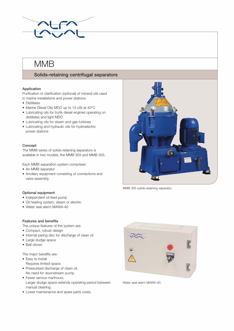
ApplicationPurification or clarification (optional) of mineral oils usedin marine installations and power stations:• Distillates• Marine Diesel Oils MDO up to 13 cSt at 40°C• Lubricating oils for trunk diesel engines operating on
distillates and light MDO• Lubricating oils for steam and gas turbines• Lubricating and hydraulic oils for hydroelectric
power stations
ConceptThe MMB series of solids-retaining separators is available in two models, the MMB 304 and MMB 305.
Each MMB separation system comprises:• An MMB separator• Ancillary equipment consisting of connections and
valve assembly
Optional equipment• Independent oil feed pump• Oil heating system, steam or electric• Water seal alarm MAWA-40
Features and benefitsThe unique features of the system are:• Compact, robust design• Internal paring disc for discharge of clean oil• Large sludge space• Belt-driven
The major benefits are:• Easy to install.
Requires limited space.• Pressurised discharge of clean oil.
No need for downstream pump.• Fewer service manhours.
Larger sludge space extends operating period betweenmanual cleaning.
• Lower maintenance and spare parts costs.
MMB 305 solids-retaining separator.
MMBSolids-retaining centrifugal separators
Water seal alarm MAWA-40.
..
..
..
..
..
13
12
1110
98
765
4
..
.
.
.
.1
.3
.2
17
16
15
14
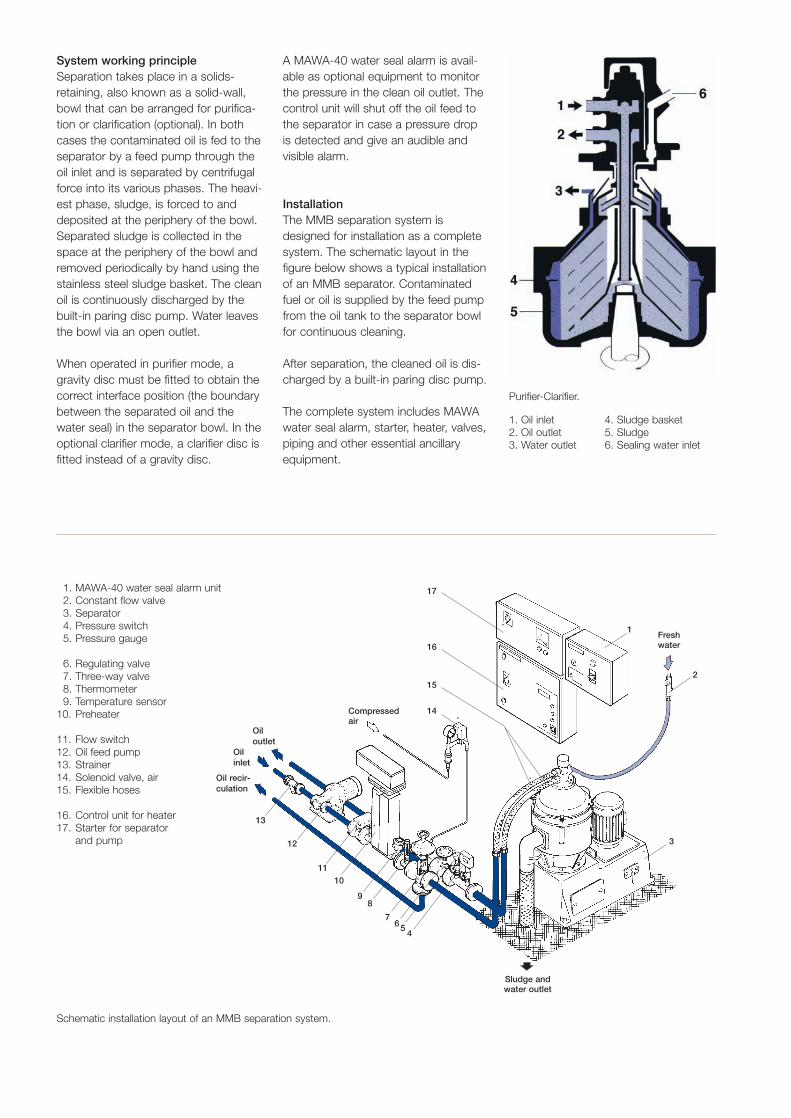
System working principleSeparation takes place in a solids-retaining, also known as a solid-wall,bowl that can be arranged for purifica-tion or clarification (optional). In bothcases the contaminated oil is fed to theseparator by a feed pump through theoil inlet and is separated by centrifugalforce into its various phases. The heavi-est phase, sludge, is forced to anddeposited at the periphery of the bowl.Separated sludge is collected in thespace at the periphery of the bowl andremoved periodically by hand using thestainless steel sludge basket. The cleanoil is continuously discharged by thebuilt-in paring disc pump. Water leavesthe bowl via an open outlet.
When operated in purifier mode, agravity disc must be fitted to obtain thecorrect interface position (the boundarybetween the separated oil and thewater seal) in the separator bowl. In theoptional clarifier mode, a clarifier disc isfitted instead of a gravity disc.
A MAWA-40 water seal alarm is avail-able as optional equipment to monitorthe pressure in the clean oil outlet. Thecontrol unit will shut off the oil feed tothe separator in case a pressure drop is detected and give an audible andvisible alarm.
InstallationThe MMB separation system isdesigned for installation as a completesystem. The schematic layout in thefigure below shows a typical installationof an MMB separator. Contaminatedfuel or oil is supplied by the feed pumpfrom the oil tank to the separator bowlfor continuous cleaning.
After separation, the cleaned oil is dis-charged by a built-in paring disc pump.
The complete system includes MAWAwater seal alarm, starter, heater, valves,piping and other essential ancillaryequipment.
Purifier-Clarifier.
1. Oil inlet 4. Sludge basket2. Oil outlet 5. Sludge3. Water outlet 6. Sealing water inlet
1. MAWA-40 water seal alarm unit2. Constant flow valve3. Separator4. Pressure switch5. Pressure gauge
6. Regulating valve7. Three-way valve8. Thermometer9. Temperature sensor
10. Preheater
11. Flow switch12. Oil feed pump13. Strainer14. Solenoid valve, air15. Flexible hoses
16. Control unit for heater17. Starter for separator
and pump
Schematic installation layout of an MMB separation system.
Freshwater
Sludge andwater outlet
Compressedair
Oil outlet
Oilinlet
Oil recir-culation

Standard design MMB 304/305The MMB 304/305 series are solids-retaining separators that are identicalin concept, with different throughputcapacities.
Each separator model comprises aframe, power transmission and bowlassembly.
The lower frame houses the flat-beltpower transmission unit connected toa vertical drive shaft with friction clutchto the vertical bowl spindle.
The bowl is fixed on top of the spindleinside the space formed by the upperpart of the frame and the frame hood.
The frame hood also contains the oilinlet and outlet and the sealing waterinlet. The separated water is dischargedby gravity through an outlet pipemounted on the frame.
Basic equipment• MMB separator• Sealing water inlet with hose nipple,
non-return valve and constant flowvalve with vacuum breaker
• Set of gravity discs• Set of resilient mountings• Stainless steel sludge basket• Flexible hoses for: oil, water outlet
and drain, and sealing water inlet• Intermediate service kit
Additional equipment required for operation• Electric motor and starter• Oil feed pump and starter• Set of tools
Optional equipment• MAWA-40 water seal alarm unit• Pressure switch kit• Three-way valve kit• Preheater• Clarifier disc• Major service kit
Technical data in brief
MMB 304 MMB 305Input voltage supply: 220/230, 380/400,
415, 440 V AC (50/60 Hz)Power consumption at max. rec. flow 1.4 kW 2.3 kWfor gas oil:
Shipping data
Dimensions (mm)MMB 304 MMB 305
A 910 935B 795 795C 465 465
Weight (kg)Type of equipment Net GrossSeparator MMB 304– without motor 185 235– with motor 201 251Separator MMB 305– without motor 190 240– with motor 218 268

Technical documentationComplete information and documen-tation accompany each separatorsystem.
After Sales supportAlfa Laval’s Preventive MaintenanceProgram is available for the MMB 300series. Alfa Laval service engineers areavailable to assist you with all types ofmaintenance and repair, and to helpyou train your personnel.
The use of genuine Alfa Laval spareparts reduces down-time and repaircosts. Spare parts kits can be orderedfrom Alfa Laval Marine Service Centersand stocked as single units.
Intermediate service kits for routinebowl maintenance and major servicekits for bowl overhaul are available.
All service kits include detailed serviceinstructions.
Throughput capacitiesThe blue bars indicate range from minimum economical throughput on detergenttype lubricating oil for trunk diesel engines to a maximum recommended through-put on distillate fuel (1.5–6 cSt/40°C). Detailed information on throughput capacitiesis provided on separate data sheets for each model.
For more detailed information see the separate data sheet of each model.
MAB 206
MMB 305
MMB 304
MAB 104
MAB 103
MAB 102
2 000 4 000 10 000l/h
0 6 000 8 000

Alfa Laval MIB 503A compact solid bowl separator for marine & diesel applications
Introduction
MIB 503 is one of the smallest separators of Alfa Laval’s solidbowl series. This product has been an upgrade of itspredecessor, MIB 303, and has been developed to fulfill allrequirements of the marine and diesel industry.
Application
This product has been designed for the removal of particlesand water from distillate, marine diesel and lubricating oils.Removal of water and particles from mineral oil improves thereliability of the oil system. It also prevents serious wear anddamages to the main engine.
Benefits
• Easy to install and start up• Easy to operate and maintain• High separation efficiency• Robust and reliable design• Lightweight materials• Small footprint
Design
The separator consists of the frame housing, the separatorbowl, the inlet and outlet device as well as the electric motor.
The frame housing is the part where the electric motor andthe bowl are fitted. The motor can easily be accessed andinspected from a hatch. The hatch is located on the front partof the housing. The complete frame is sitting on rubberdampers which absorb all vibrations during operation.
The separator consists of a solids-retaining bowl which,depending on the application, can be used both as purifier orclarifier.
The MIB 503 is one extremely lightweight design. The outerparts of the bowl are manufactured in surface-coatedaluminium and most of the inner parts i.e. the disc stack, thebottom disc and the inlet cone are manufactured in high-grade polymer composite.
The unique drive technology is based on an electric motormounted directly to the bowl compared to conventionaldesign of gear and belt systems.
Scope of supply
• Frame housing• Separator bowl• Inlet & outlet device• Electric motor, direct driven• Set of plates• Documentation
Options
• Bowl conversion kit• Service kits• Set of tools
Working principle
The purifier operation takes place in the rotating solid-wallbowl. When the bowl is set as a purifier the uncleaned oil isfed into the bowl where the centrifugal force makes water andsolid particles move out towards the periphery of the bowl,while the clean oil flows inwards.
To establish a water seal during start-up of the separator,water is added to the bowl before the oil feed is started. The

water collects in the water seal which drains into the waterchannel below the bowl.
The solids accumulate on the bowl wall and are removedperiodically by hand. The cleaned oil flows towards the centreof the bowl and up to the paring disc. Since the oil is rotating,the stationary paring disc acts as a pump which forces theoil out through the outlet under pressure.
During the clarifier operation, the oil normally does not containany free water. The separation principle is similar to thepurifier, however there is no water seal, no water outlet andthe water handling capacity is limited.
34 5
6
8
10
7
9
11
12
14
13
1 2
The MIB 503 section drawing is illustrating the basic parts of theseparator bowl.
1. Inlet2. Outlet3. Paring disc4. Paring disc chamber5. Lever ring6. Paring chamber lower7. Lock nut8. Centre rod9. Inlet cone
10. Bowl wall11. Bowl discs12. Bottom disc (clarifier version)13. Bottom disc (purifier version)14. Bowl bottom
Technical data Performance data
Hydraulic capacity1 1,25 m3/h (4,58 US gpm)
Separation temperature for distillate/marine diesel oils
40°C
Separation temperature for
lubricating oil295°C
Maximum density 920 kg/m3 at 15°C
Maximum motor power 0,45 kW (0,60 HP)
Sound pressure level 62 dB(A2)
1 Actual capacities depend on operating conditions
2 The maximum separation temperature of the separator
Connections
Feed inlet ISO-G 3/8 inch
Light liquid phase outlet ISO-G 3/8 inch
Heavy phase outlet Ø 27 mm
Material data
Frame housing parts Surface-coated aluminum
Separator bowl partsSurface-coated aluminum, High-gradepolymer composite
In and outlet parts Surface-coated aluminum
Gaskets and O-rings Fluorocarbon rubber (Viton®)
Weights (approximate)
Separator weight incl. bowl andmotor
18 kg (39,7 lbs)
Bowl weight 4 kg (8,8 lbs)
Dimensional drawing
W2W1
H1
H2
Dimensions
H1 Min. 729 mm (2 ft 4 11/16 inch)
H2 479 mm (1 ft 6 7/8 inch)
W1 280 mm (11 inch)
W2 280 mm (11 inch)

Alfa Laval Oil Cleaning Module
OCM cleaning solutions for mineral oils
Clean oil is crucial for the safe, reliable and economicaloperation of virtually all kinds of equipment that uses oils foreither lubrication or hydraulic systems. Clean oil reduces wearand corrosion on all equipment installed downstream, thushelping avoid breakdowns and cutting back on downtimethroughout a plant or installation.
The Alfa Laval Oil Cleaning Module (OCM) provides rapid,effective separation of the oil, water and sludge componentsin contaminated mineral lubricating and hydraulic oils – all atthe same time.
The benefits include lower operating costs due to reduced oilconsumption, lower disposal costs and improvements in bothproduct quality and the working environment.
Easy to operate oil purificationThe Alfa Laval Oil Cleaning Module is a modularized systemwith all the component systems fully integrated, ensuringeasy operation while engaged in oil cleaning duties. At theheart of this compact, easy-to-use equipment is an AlfaLaval disc stack centrifuge of supreme efficiency.
Alfa Laval Oil Cleaning Modules are available with all compo-nents and systems pre-configured on a skid, for easy, rapidinstallation and ready for immediate use. They ensure theeffective removal of particles and water in the oil. If an emer-gency arises, even a high level of water contaminants can beremoved.
An OCM provides continuous purification of lubricating andhydraulic oils while the equipment in which they are used is inoperation. If required, the OCM can continue operating whilethe primary equipment is at a standstill.
The impact of contaminants in oilContaminants in lubricating and hydraulic oils have seriouseffects on system performance, operating costs and durability.For example, the presence of solid particles:• abrades metal surfaces• increases friction• clogs filters
Similarly, if water is present in the oil, this:• causes corrosion• reacts with additives
• forms oil/water emulsions• causes significant deterioration in the performance of the oil.
Cleanliness countsOCM oil cleaning modules are specifically designed toremove contaminant particles, solid impurities and free waterfrom mineral lubricating and hydraulic oils.This is important because clean, uncontaminated oil:
• extends the service life of all kinds of equipment by asmuch as 50%
• eliminates or reduces corrosion by removing free waterpresent in the oil
• ensures longer uptime operation, thus boosting productivity• results in significant reductions in machinery wear andbreakdowns
• cuts operating costs by reducing oil consumption• extends oil service life and therefore reduces replacementand disposal costs
• improves both product quality and the working environ-ment.
Complete OCM 304

Fig. 1 OCM capacity table – ISO VG 46 lubricating oil separationtemperature of 70°C. For steam turbines, the cleaning capacityshould be based on 10% of the total charge of lubricating oil,unless stated otherwise by the turbine manufacturer.
Cleaning capacities for turbine lubricating oil
OCM 206
OCM 305
OCM 304
OCM 104
OCM 103
0 1000 2000 3000 4000 5000 6000 7000 8000
litres per hour
Cleaning capacities for hydraulic oil and lubricatingoil for the steel and paper industries
OCM 206
OCM 305
OCM 304
OCM 104
OCM 103
0 500 1000 1500 2000 2500 3000 3500 4000
litres per hour
Fig. 2 OCM capacity table – Maximum flow at viscosity 20 cSt atseparation temperature.
Features and benefits• Simple skid-mounted design that is compact and robust• Removes both solids and water at the same time, and ona continuous basis
• Easy, rapid start-up procedure• Low operating costs• Low maintenance requirements, with easy access• Eliminates need to dispose of filter cartridges, ensuring thatsludge disposal has minimal environmental impact
• Extremely reliable, ensuring long service life.
Standard OCM equipmentEach unit comprises:
1. Disc stack centrifuge to separate out solids and water2. Electric motor to drive separator3. Electric heater4. Oil feed pump with motor5. Combined starter and water seal alarm6. Base plate and frame (mobile or stationary)
1
2
4
5
6
3
1. Contaminated oil inlet2. Clean oil outlet3. Water outlet4. Sludge basket5. Water space6. Sealing water inlet
Operating principleSeparation takes place in a disc stack centrifuge. The feed ispumped into the centrifuge where centrifugal force separatesthe feed liquid into its different phases.
The heaviest of these phases – sludge and water – are forcedto the periphery of the bowl. The sludge component isdeposited in the sludge space and must be removed manuallyat regular intervals. The clean oil and the separated water aredischarged on a continuous basis.
Fig. 3 Purifier-clarifier unit
Oil cleaning capacities

InstallationThe oil cleaning module is normally installed in a by-passsystem, treating a specified percentage of the full flow ofcontaminated oil. Tank-to-tank installation is also possible.
The suction line from the lubricating or hydraulic oiltank/sump is installed in the lowest end of the tank, typically1/3 from the bottom. This ensures that any dirty oil present istreated promptly. The suction height should be as low aspossible in order to reduce or eliminate any pump cavitationeffect.
The oil return line is connected to the top of the oil tankopposite to the oil suction in order to ensure proper oil circu-lation during cleaning also when the turbine is out of opera-tion.
50 Hz
Feed pump
Water
HeaterStarter andcontrol unit
Equipment included with the OCM
Fig. 4 System diagram
Technical specificationsPower supply: 400/415/440 VAC (50/60 Hz)Oil grades: all lubricating and hydraulic oils in normal use, aswell as marine diesel oil and distillatesWater supply: demineralized water at a pressure of 2–6 bar
Module type OCM 103 OCM 104 OCM 304 OCM 305 OCM 206Separator motor, kW (50/60 Hz) 0.75/0.9 1.5/1.8 2.2/2.5 3.0/3.7 5.5/6.4Feed pump, kW Integral Integral 0.37/0.43 0.75/0.86 1.5/1.75Heater, kW 14 22 22 36 65
Separation performanceParticles: ≤ 5 micron 90% removalParticle: ≤ 3 micron 70% removalWater: Removal is typically in the range of 90%.
After-sales supportThe Alfa Laval preventive maintenance programme is availablefor the OCM series. Alfa Laval service engineers are availableto assist you with all types of maintenance and repair, as wellas to help you train your personnel in operating and maintain-ing these units.
Using genuine Alfa Laval spare parts reduces downtime andrepair costs. Spare parts kits can be ordered from Alfa LavalService Centres.
Intermediate service kits for routine bowl maintenance andmajor service kits for separator overhaul are also available.

50 Hz
L W
H
Dimensions
Fig. 5. Dimensions
Net Weight in kg Gross
crate box L W H L W H truck sea
mm 1,150 850 1,260 325 mm 1,500 1,000 1,700 475 525
mm 1,285 760 1,445 345 mm 1,500 1,000 1,750 495 545
mm 1,450 850 1,260 455 mm 2,000 1,000 1,700 625 695
mm 1,585 760 1,445 485 mm 2,000 1,000 1,750 655 725
mm 1,450 850 1,260 525 mm 2,000 1,000 1,700 660 730
mm 1,650 760 1,445 545 mm 2,000 1,000 1,750 690 760
mm 1,450 850 1,260 525 mm 2,000 1,000 1,700 695 765
mm 1,650 760 1,445 545 mm 2,000 1,000 1,750 720 790
mm 1,950 1,200 1,500 1,040 mm 2,500 1,300 2,050 1,370 1,460
mm 2,085 1,110 1,683 1,100 mm 2,500 1,300 2,050 1,430 1,520
Dimensions Weight in kg
OCM 305 Stationary
OCM 104 Stationary
OCM 104 Mobile
Dimensions
OCM 103 Stationary
OCM 103 Mobile
OCM 305 Mobile
OCM 206 Stationary
OCM 206 Mobile
OCM 304 Stationary
OCM 304 Mobile
(inch /25.4) (lbs *2.2046) (inch /25.4) (lbs *2.2046)

Merco Energy Saver E-10 High Efficiency Nozzles
General A new type of nozzle for the installed base of Merco machines has been developed. The nozzle will decrease power consumption by 10%.
The replacements are valid for old nozzles with part number 26010S.
AdvantagesThe advantages of the new nozzles are:
• Power savings- Lower production cost- Environmental proceeds
• Extended nozzle life• Easy installation and removal
Power savingsPower saving of 10% signifies profit as well as environmental earnings. For the average machine power savings can easily justify the replacement of the nozzles. Please contact Alfa Laval for a customer specific power savings calculation.
Extended nozzle lifeThe new nozzle is made in one piece of abrasive resistant metal, thus eliminating problems due to brazing.
The smooth flow transition inner chamber minimizes the hydraulic losses and also contributes to prolonged nozzle life.
Easy installation and removalThe dove-tail shape allows firm grip of the tool for easy installation and removal.
New Nozzle and Tool
The nozzle 576327 is available in sizes from 65E-10 to 11E-10. See table on page 2 for reference.
08-ALC-031_Merco Energy Nozzles PDF Sheet_v3.indd 1 12/16/08 8:59:47 AM

OrdersRemember to order:
• Nozzle tool 577086-80 with first delivery.• The O-ring M12155 is required for each nozzle.
The nozzles should be handled separately to minimize the risk of damage, since they are made of a brittle material.
Item numbers for new nozzels according to below table.
Size Ø New nozzle P/N
65E-10 0,90 576327-01
60E-10 1,00 576327-02
56E-10 1,15 576327-03
53E-10 1,50 576327-04
50E-10 1,80 576327-05
46E-10 2,00 576327-06
43E-10 2,25 576327-07
40E-10 2,50 576327-08
38E-10 2,60 576327-09
36E-10 2,70 576327-10
34E-10 2,80 576327-11
32E-10 2,95 576327-12
30E-10 3,25 576327-13
28E-10 3,55 576327-14
24E-10 3,85 576327-15
20E-10 4,10 576327-16
18E-10 4,30 576327-17
15E-10 4,60 576327-18
11E-10 4,80 576327-19
New Nozzle Tool
A nozzle tool 577086-80 is needed and should be ordered together with first time delivery of the new nozzles.
08-ALC-031_Merco Energy Nozzles PDF Sheet_v3.indd 2 12/16/08 8:59:48 AM

Merco Energy Saver E-25 High Efficiency Nozzles
A new high efficiency nozzle has been developed for the Merco product line. The nozzle will decrease power consumption by 25 percent or more depending on application/duty.
Quick payback timeSave money by using less energy, thanks to the advanced design of the high efficiency E-25 nozzle. Alfa Laval modifies your existing rotor assembly with nozzle openings to accommodate new nozzle bushings. With energy savings of 25 percent or more, your investment in upgrading quickly pays for itself.
Easy maintenanceUpgrading makes your Alfa Laval Merco separator easier to maintain than previous models. Convenient to install and remove, the new E-25 nozzle reduces the amount of time and labor required for routine maintenance.
With the Energy Saver Upgrade, new replaceable bushings are installed in the nozzle opening in the bowl wall. The bushings provide extra protection and minimize the risk of damage to the bowl wall.
More eco-friendlyBy enhancing your Merco separators with E-25 nozzles, your wet milling processes instantly become more environmentally sound, thanks to energy savings that reduce your plant’s carbon emissions.
Extended nozzle lifeUpgrade your existing nozzles with our new high efficiency E-25 nozzles. The impressive E-25 nozzle design raises the bar on performance. The nozzles are made of highly wear-resistant material and are designed to minimize turbulence. These improvements prolong the service life of the E-25 nozzle.
NOTE! The replacements are valid only for rotor and hub assemblies upgraded with bushings.
The bushings are needed both to achieve the power savings as well as protect the body in the unlikely event of a broken nozzle.
New Nozzle Tool
Only rotor and hub assemblies for the H-30 and H-36 machines delivered by Alfa Laval and made of forged stainless steel 2377 can be modified to the new design.
The advantages of the new nozzles are:
• Energy savings of 25 percent or more• Longer nozzle life• Easier to install• Easier maintenance
Scope (based on return of Rotor Bowl/Hub only):• Disassemble, clean and inspect Rotor Bowl/Hub Assembly
(B&H Assembly)
• Bore nozzle opening to accommodate new nozzle bushings
• Install new bushings, high efficiency nozzles (size to bespecified by customer) and lower shaft assembly
• Balance Rotor Bowl/Hub Assembly to OEM specifications
• Prepare Rotor Bowl/Hub for shipment (nozzles will beshipped in a separate box for assembly by customer duringRotor installation).
Additional options:(1) piece 577086-80 Nozzle Tool
08-ALC-020_Energy Saver PD Sheet_v8.indd 1 12/16/08 8:58:33 AM

(2) pieces 576565-81 Lifting Tool
Contact Denny Dearing at the Greenwood Repair Center for additional information or to schedule the above upgrade at 317-889-3022 or email: [email protected]
Remember to order the nozzle tool 577086-80 and the O-ring 260168-46 for each nozzle.
The nozzles should be handled separately to minimize the risk of damage, since they are made of a brittle material.
Part numbers for new nozzles according to below table:
New Nozzle P/N Size Ø577036-01 65E-25 0,9577036-02 60E-25 1577036-03 56E-25 1,15577036-04 53E-25 1,5577036-05 50E-25 1,8577036-06 46E-25 2577036-07 43E-25 2,25577036-08 40E-25 2,5577036-09 38E-25 2,6577036-10 36E-25 2,7577036-11 34E-25 2,8577036-12 32E-25 2,95577036-13 30E-25 3,25577036-14 28E-25 3,55577036-15 24E-25 3,85577036-16 20E-25 4,1577036-17 18E-25 4,3577036-18 15E-25 4,6577036-19 11E-25 4,8577036-20 9E-25 5
Model New B&H P/N Existing B&H P/N
H-30 GT/CL/MST 581456-80 01A18683-02
H-30 PRIM 581456-82 01B15719-02
Model H-36 T/F 581454-80 01B13916-02
Model H-36 B/F 581454-81 01B12989-01
H-36B PRIM 581453-81 01B14370-02
H-36B GT/CL/MST 581453-80 01B14658-02
LPCH-30 PTA 581456-81 01A18683-03
1. Nozzle 5770362. O-ring p/n 260168-463. Bushing p/n 575647-014. O-ring p/n 223404-635. B&H Assembly
The rotor bowl and hub assemblies manufactured by Dorr-Oliver can not be modified, but they can be replaced with the new forged assemblies with bushings acc to below table.
08-ALC-020_Energy Saver PD Sheet_v8.indd 2 12/16/08 8:58:33 AM
Архангельск (8182)63-90-72 Астана (7172)727-132 Астрахань (8512)99-46-04 Барнаул (3852)73-04-60 Белгород (4722)40-23-64 Брянск (4832)59-03-52 Владивосток (423)249-28-31 Волгоград (844)278-03-48 Вологда (8172)26-41-59 Воронеж (473)204-51-73 Екатеринбург (343)384-55-89 Иваново (4932)77-34-06
Ижевск (3412)26-03-58 Иркутск (395)279-98-46 Казань (843)206-01-48 Калининград (4012)72-03-81 Калуга (4842)92-23-67 Кемерово (3842)65-04-62 Киров (8332)68-02-04 Краснодар (861)203-40-90 Красноярск (391)204-63-61 Курск (4712)77-13-04 Липецк (4742)52-20-81 Киргизия (996)312-96-26-47
Магнитогорск (3519)55-03-13 Москва (495)268-04-70 Мурманск (8152)59-64-93 Набережные Челны (8552)20-53-41 Нижний Новгород (831)429-08-12 Новокузнецк (3843)20-46-81 Новосибирск (383)227-86-73 Омск (3812)21-46-40 Орел (4862)44-53-42 Оренбург (3532)37-68-04 Пенза (8412)22-31-16 Казахстан (772)734-952-31
Пермь (342)205-81-47 Ростов-на-Дону (863)308-18-15 Рязань (4912)46-61-64 Самара (846)206-03-16 Санкт-Петербург (812)309-46-40 Саратов (845)249-38-78 Севастополь (8692)22-31-93 Симферополь (3652)67-13-56 Смоленск (4812)29-41-54 Сочи (862)225-72-31 Ставрополь (8652)20-65-13 Таджикистан (992)427-82-92-69
Сургут (3462)77-98-35 Тверь (4822)63-31-35 Томск (3822)98-41-53 Тула (4872)74-02-29 Тюмень (3452)66-21-18 Ульяновск (8422)24-23-59 Уфа (347)229-48-12 Хабаровск (4212)92-98-04 Челябинск (351)202-03-61 Череповец (8202)49-02-64 Ярославль (4852)69-52-93
https://alaval.nt-rt.ru || [email protected]