algorithm for synthesis and exploration of clock … for synthesis and exploration of clock spines...
TRANSCRIPT
Algorithm for Synthesis and Exploration of Clock spines
Youngchan Kim, Taewhan KimDepartment of Electrical and Computer Engineering
Seoul National University, Korea

Clock Distribution Network
Clock MeshHigh resource consumptionTolerance to timing variation
Cross LinksCompromises clock resourcewith timing variation
Clock spineAnother alternativeto the clock tree with links
Clock TreeLow resource consumptionSuffers timing variation

Clock Spine Network Structure
Clock spineHorizontal or vertical wire
Sinks with stubsEvery sink is attachedto its nearby spine
Spine buffersDrive clock spines and sinks
Top-level treeDeliver the clock signal fromSource to sink
Multiple clock pathsTolerance to timing variation

Overall Synthesis Flow
Synthesize top-level treeDrives spine buffers
Synthesize the clock spineSpine allocation and placementStub allocationBuffer allocation
Refine the spine networkSpine mergingSpine extension
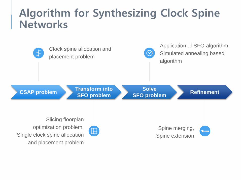
Algorithm for Synthesizing Clock Spine Networks
Clock spine allocation and placement problem
CSAP problem Transform intoSFO problem
SolveSFO problem Refinement
Slicing floorplanoptimization problem,
Single clock spine allocation and placement problem
Application of SFO algorithm,Simulated annealing based algorithm
Spine merging,Spine extension

Clock Spine Allocation and Placement Problem
GivenPlaced clock sinksBuffer library ƁConstraints- Lbound: minimum length of clock spine- lbound: maximum length of stub wire- The number of clock spines N
…
ObjectiveGenerate a clock spine network SMinimizes the quantity𝐶𝐶 𝑆𝑆 = 𝛼𝛼1𝑊𝑊𝐿𝐿𝑠𝑠𝑠𝑠 𝑆𝑆 + 𝛼𝛼2𝑊𝑊𝐿𝐿𝑠𝑠𝑠𝑠 𝑆𝑆 + 𝛽𝛽𝐵𝐵𝐵𝐵(𝑆𝑆)
Lbound
lbound
> lbound< Lbound

Slicing Floorplan Optimization Problem
GivenPlane of 𝑚𝑚 × 𝑛𝑛 gridsCost function 𝑓𝑓(𝑏𝑏) for a rectangle blockParameters- The number of sliced blocks N
ObjectiveGenerate a slicing floorplan ℱby recursively slicing the plane 𝑁𝑁 − 1 timesMinimizes the quantity
𝐶𝐶′ ℱ = 𝑓𝑓 𝑏𝑏1 + 𝑓𝑓 𝑏𝑏2 + ⋯+ 𝑓𝑓(𝑏𝑏𝑁𝑁)
𝑓𝑓(𝑏𝑏1) 𝑓𝑓(𝑏𝑏2)
𝑓𝑓(𝑏𝑏3)
𝐶𝐶′ ℱ = 𝑓𝑓 𝑏𝑏1 + 𝑓𝑓 𝑏𝑏2 + 𝑓𝑓(𝑏𝑏3)
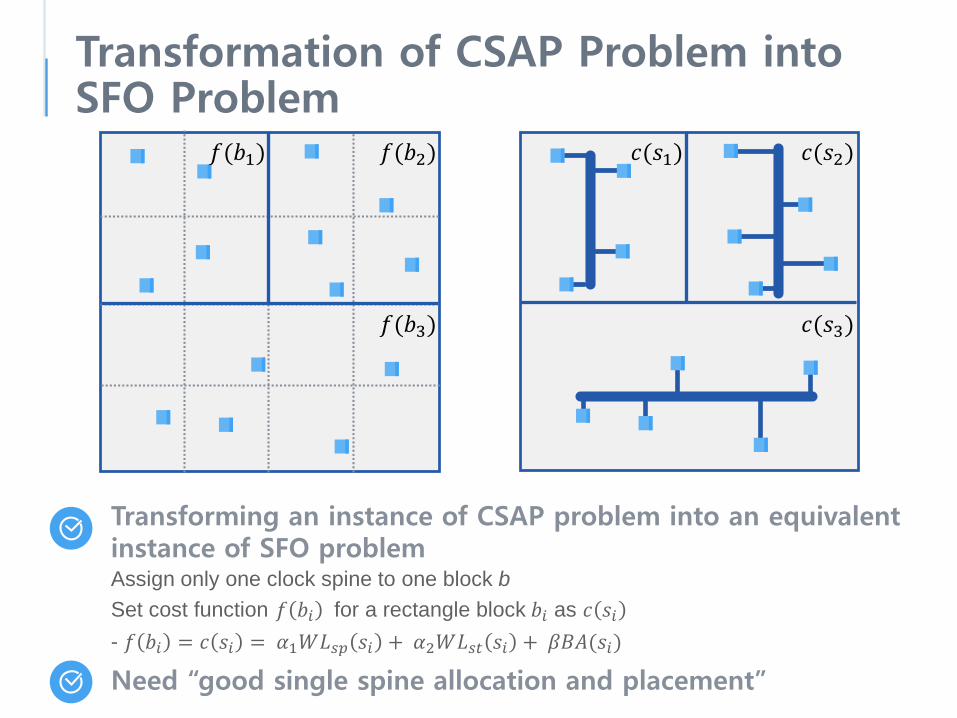
Transformation of CSAP Problem into SFO Problem
Transforming an instance of CSAP problem into an equivalent instance of SFO problemAssign only one clock spine to one block bSet cost function 𝑓𝑓 𝑏𝑏𝑖𝑖 for a rectangle block 𝑏𝑏𝑖𝑖 as 𝑐𝑐 𝑠𝑠𝑖𝑖- 𝑓𝑓 𝑏𝑏𝑖𝑖 = 𝑐𝑐 𝑠𝑠𝑖𝑖 = 𝛼𝛼1𝑊𝑊𝐿𝐿𝑠𝑠𝑠𝑠 𝑠𝑠𝑖𝑖 + 𝛼𝛼2𝑊𝑊𝐿𝐿𝑠𝑠𝑠𝑠 𝑠𝑠𝑖𝑖 + 𝛽𝛽𝐵𝐵𝐵𝐵(𝑠𝑠𝑖𝑖)
𝑓𝑓(𝑏𝑏1) 𝑐𝑐(𝑠𝑠1)𝑓𝑓(𝑏𝑏2) 𝑐𝑐(𝑠𝑠2)
𝑓𝑓(𝑏𝑏3) 𝑐𝑐(𝑠𝑠3)
Need “good single spine allocation and placement”

Single Clock Spine Allocation and Placement
GivenA set of clock sinks in a block bBuffer library ƁParameters- Lbound
- lbound
…
ObjectiveAllocate a clock spine s to one blockMinimizes the quantity𝑓𝑓 𝑏𝑏𝑖𝑖 = 𝑐𝑐 𝑠𝑠𝑖𝑖= 𝛼𝛼1𝑊𝑊𝐿𝐿𝑠𝑠𝑠𝑠 𝑠𝑠𝑖𝑖 + 𝛼𝛼2𝑊𝑊𝐿𝐿𝑠𝑠𝑠𝑠 𝑠𝑠𝑖𝑖 + 𝛽𝛽𝐵𝐵𝐵𝐵(𝑠𝑠𝑖𝑖)
Lbound
lbound
> lbound< Lbound

How to Allocate One Spine to One BlockSpine directionsHorizontal / Vertical- Direction with lower cost is selected- Lbound
Buffer allocationWith buffer library ƁExhaustive trial- Set maximum driving
capacitance for each buffer in Ɓ- Meet slew constraint- Minimize BA(.) cost
…
Stub allocationDetermined by position of spineSweep the spine back and forth- Minimize WLst(.) cost- lbound
> lbound

Application of SFO Algorithm
Any SFO algorithm can be appliedSimulated annealing (SA) method based on the postfix expression- proposed by Wong and Liu [16]
Postfix expression of slicing floorplan
+2
*2
+1
+3
+2
*1 *2 *3
b1 b2
b3
b1 b2
b3● ● *2● +2
[16] D. F. Wong and Cl. L. Liu, “A new algorithm for floorplan design,” DAC, 1986.

Application of SFO Algorithm
Move operationsTo traverse solution space of SFO problem- Change the index of operator- Complement an operator- Swap operators- Swap an operator with a bullet
+1
+3
+2
*1 *2 *3
b1 b2
b3
+2
*2
b1 b2
b3
● ● *2● +2+3
+1
+3
+2
*1 *2 *3
b1b2
b3
● ● *2● +3
*2
+3
● ● +3 ● *2
+1
+3
+2
*1 *2 *3
b1
b2
b3
Cost function for simulated annealing𝐶𝐶′ ℱ = 𝑓𝑓 𝑏𝑏1 + 𝑓𝑓 𝑏𝑏2 + ⋯+ 𝑓𝑓(𝑏𝑏𝑁𝑁)- 𝑓𝑓 𝑏𝑏𝑖𝑖 = 𝑐𝑐 𝑠𝑠𝑖𝑖 = 𝛼𝛼1𝑊𝑊𝐿𝐿𝑠𝑠𝑠𝑠 𝑠𝑠𝑖𝑖 + 𝛼𝛼2𝑊𝑊𝐿𝐿𝑠𝑠𝑠𝑠 𝑠𝑠𝑖𝑖 +𝛽𝛽𝐵𝐵𝐵𝐵(𝑠𝑠𝑖𝑖)

Refinement of Clock Spine Network
Isolated clock sinksVariability vulnerable sinksTo convert all isolated clock sinks to unisolatedones
Spine MergingMerge two nearby spines- Distance threshold dmax
- Resize nearby buffers to drive merged spine
< dmax
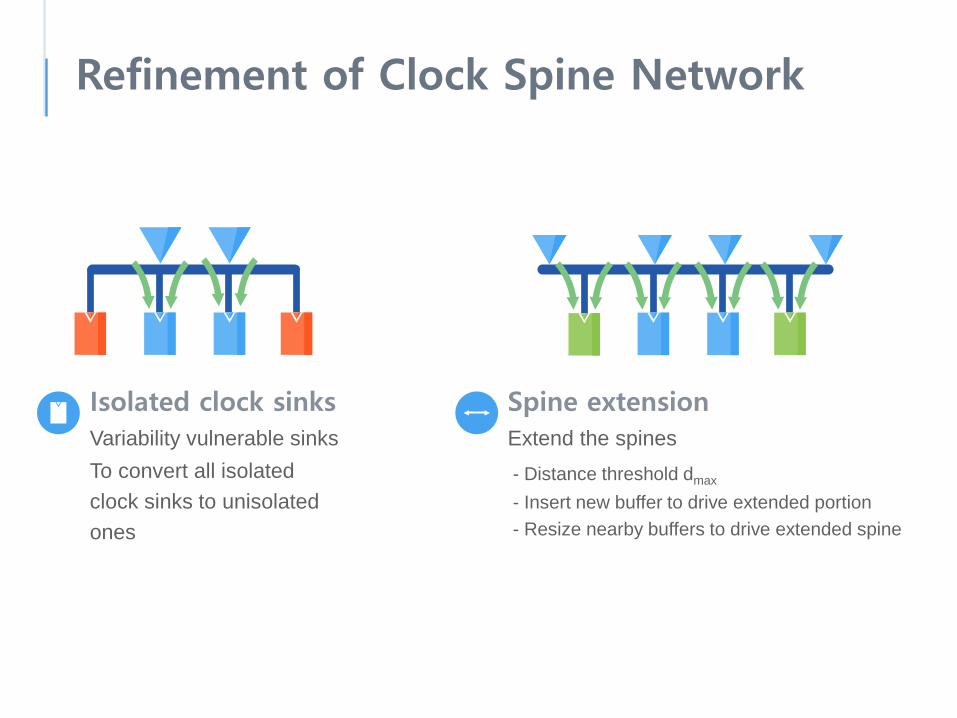
Refinement of Clock Spine Network
Spine extensionExtend the spines- Distance threshold dmax
- Insert new buffer to drive extended portion- Resize nearby buffers to drive extended spine
Isolated clock sinksVariability vulnerable sinksTo convert all isolated clock sinks to unisolatedones
Experimental Environments
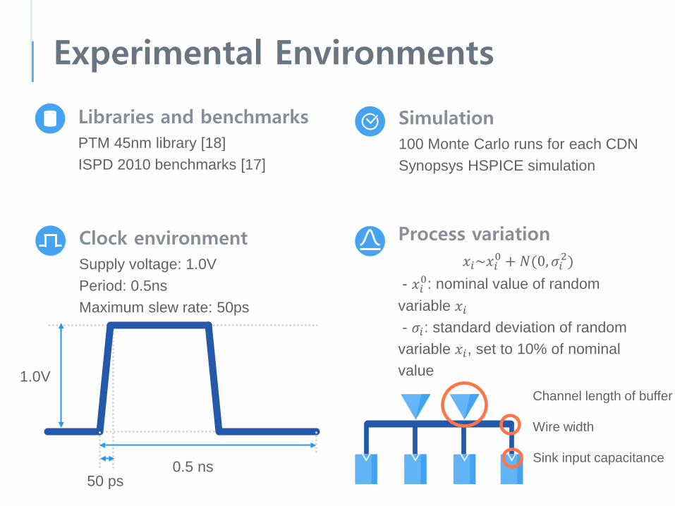
Libraries and benchmarksPTM 45nm library [18]ISPD 2010 benchmarks [17]
Clock environmentSupply voltage: 1.0VPeriod: 0.5nsMaximum slew rate: 50ps
1.0V
0.5 ns50 ps
Process variation𝑥𝑥𝑖𝑖~𝑥𝑥𝑖𝑖0 + 𝑁𝑁(0,𝜎𝜎𝑖𝑖2)
- 𝑥𝑥𝑖𝑖0: nominal value of random variable 𝑥𝑥𝑖𝑖- 𝜎𝜎𝑖𝑖: standard deviation of random variable 𝑥𝑥𝑖𝑖, set to 10% of nominal value
Wire width
Sink input capacitance
Channel length of buffer
Simulation100 Monte Carlo runs for each CDNSynopsys HSPICE simulation
Experimental Environments
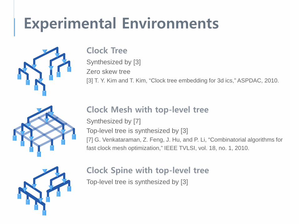
Clock TreeSynthesized by [3]Zero skew tree[3] T. Y. Kim and T. Kim, “Clock tree embedding for 3d ics,” ASPDAC, 2010.
Clock Mesh with top-level treeSynthesized by [7]Top-level tree is synthesized by [3][7] G. Venkataraman, Z. Feng, J. Hu, and P. Li, “Combinatorial algorithms for fast clock mesh optimization,” IEEE TVLSI, vol. 18, no. 1, 2010.
Clock Spine with top-level treeTop-level tree is synthesized by [3]

Experimental Results
Global clock skewUnit: psMean value of 100 Monte Carlo runs38% decreased skew than clock tree8.7% higher than clock mesh
03.in 05.in04.in0
30
60
10
20
40
50
70
06.in 07.in 08.in
tree spine mesh

Experimental Results
Total wire lengthUnit: μm5% decreased wire usagethan clock tree
tree spine mesh
04.in 05.in 06.in 07.in 08.in03.in
0
100000
50000
150000
200000

Experimental Results
Total buffer areaUnit: μm2
15% higher buffer area than clock tree6% usage compared to the clock mesh
tree spine
0
800
400
1200
1600
03.in 04.in 05.in 06.in 07.in 08.in
Experimental Results
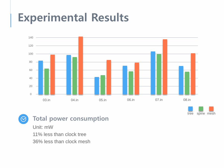
Total power consumptionUnit: mW11% less than clock tree36% less than clock mesh
tree spine mesh
03.in 05.in 06.in 07.in 08.in04.in
0
40
20
60
80
100
120
140

Experimental Results
Clock spine synthesis considering clock gatingComparison of results of clock-gating aware clock spine synthesis in [14] and oursCost function is updated- 𝑐𝑐 𝑠𝑠𝑖𝑖 = 𝛼𝛼1𝑊𝑊𝐿𝐿𝑠𝑠𝑠𝑠 𝑠𝑠𝑖𝑖 + 𝛼𝛼2𝑊𝑊𝐿𝐿𝑠𝑠𝑠𝑠 𝑠𝑠𝑖𝑖 + 𝛽𝛽𝐵𝐵𝐵𝐵 𝑠𝑠𝑖𝑖 + 𝜸𝜸𝑷𝑷𝑷𝑷𝑷𝑷(𝒔𝒔𝒊𝒊)22% less clock skew40% less wire length60% less buffer area45% less power consumption
tree spine
0
20
10
30
40
50
03.in 04.in 05.in 06.in 07.in 08.in
[14] H. Seo, J. Kim, M. Kang, and T. Kim,“Synthesis for power-aware clock spines,” ICCAD, 2011.

Conclusions
Addressed the problem of automating the synthesis of clock spine networksNever been automated as yet
Clock spine is tolerant to the clock skew variation while using less resource and powerComparable to the clock mesh

Q & A