algorithmic model system-level modelling and …mpsoc.unife.it/~arch-dig/slides2016/busses.pdf ·...
TRANSCRIPT
Algorithmic model
UnTimed Functional (UTF) model
Timed Functional (TF) model
Abs
trac
tion
leve
lSi
mul
atio
n sp
eed
Sim
ulat
ion
accu
racy
Synt
hesi
zabi
lity
Bus Cycle Accurate (BCA) model
Cycle Accurate (CA) model
Register Transfer Level (RTL) model
Create Floorplan Create Power Grid Placement
Clock tree synthesis(CTS) Routing Post-routing optimization
Bac
k-En
d Sy
nthe
sis
Flow
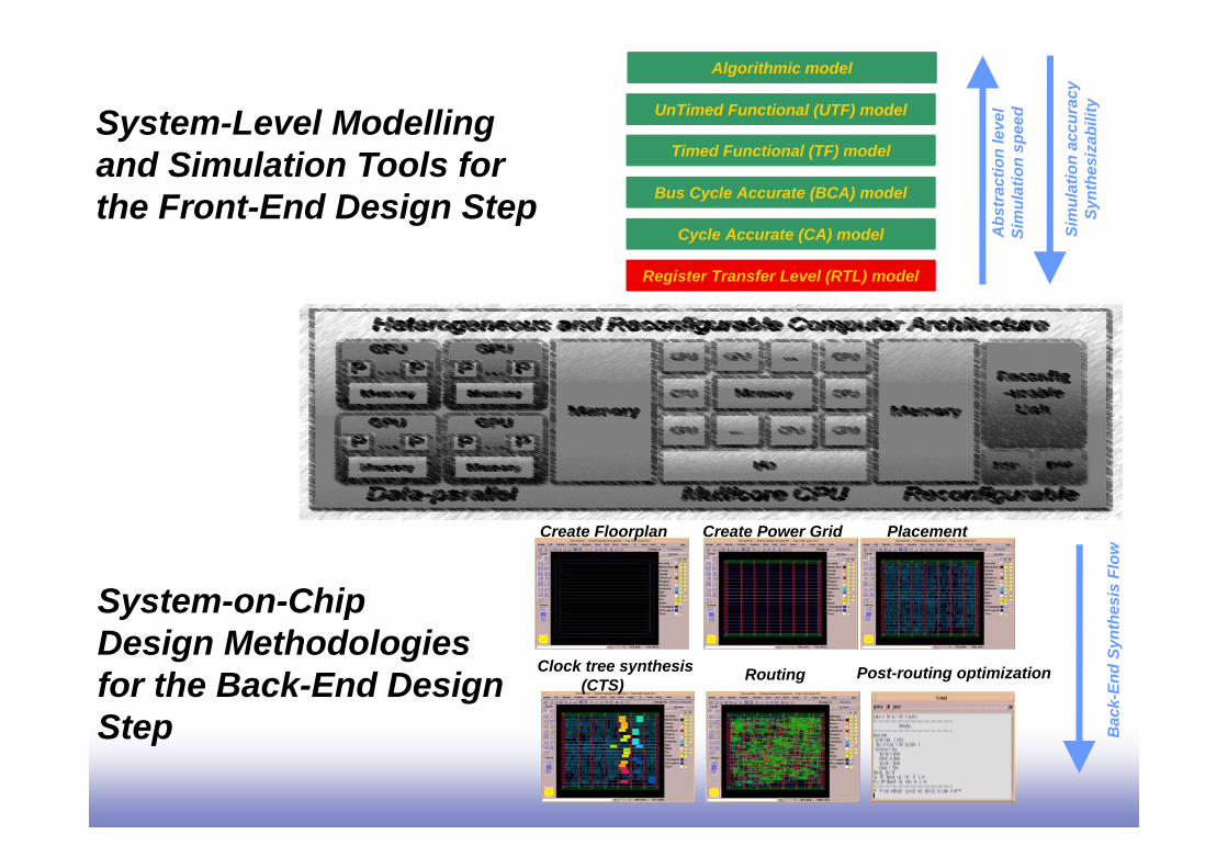
System-Level Modelling and Simulation Tools for the Front-End Design Step
System-on-ChipDesign Methodologiesfor the Back-End Design Step

Algorithmic model
UnTimed Functional (UTF) model
Timed Functional (TF) model
Abs
trac
tion
leve
lSi
mul
atio
n sp
eed
Sim
ulat
ion
accu
racy
Synt
hesi
zabi
lity
Bus Cycle Accurate (BCA) model
Cycle Accurate (CA) model
Register Transfer Level (RTL) model
Create Floorplan Create Power Grid Placement
Clock tree synthesis(CTS) Routing Post-routing optimization
Bac
k-En
d Sy
nthe
sis
Flow
What do wehave to design?

Let us start from the communication backbonefor the system as a whole!
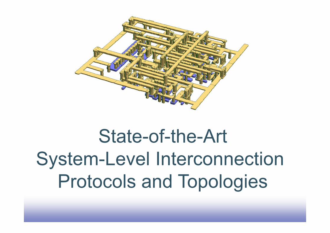
State-of-the-ArtSystem-Level Interconnection
Protocols and Topologies
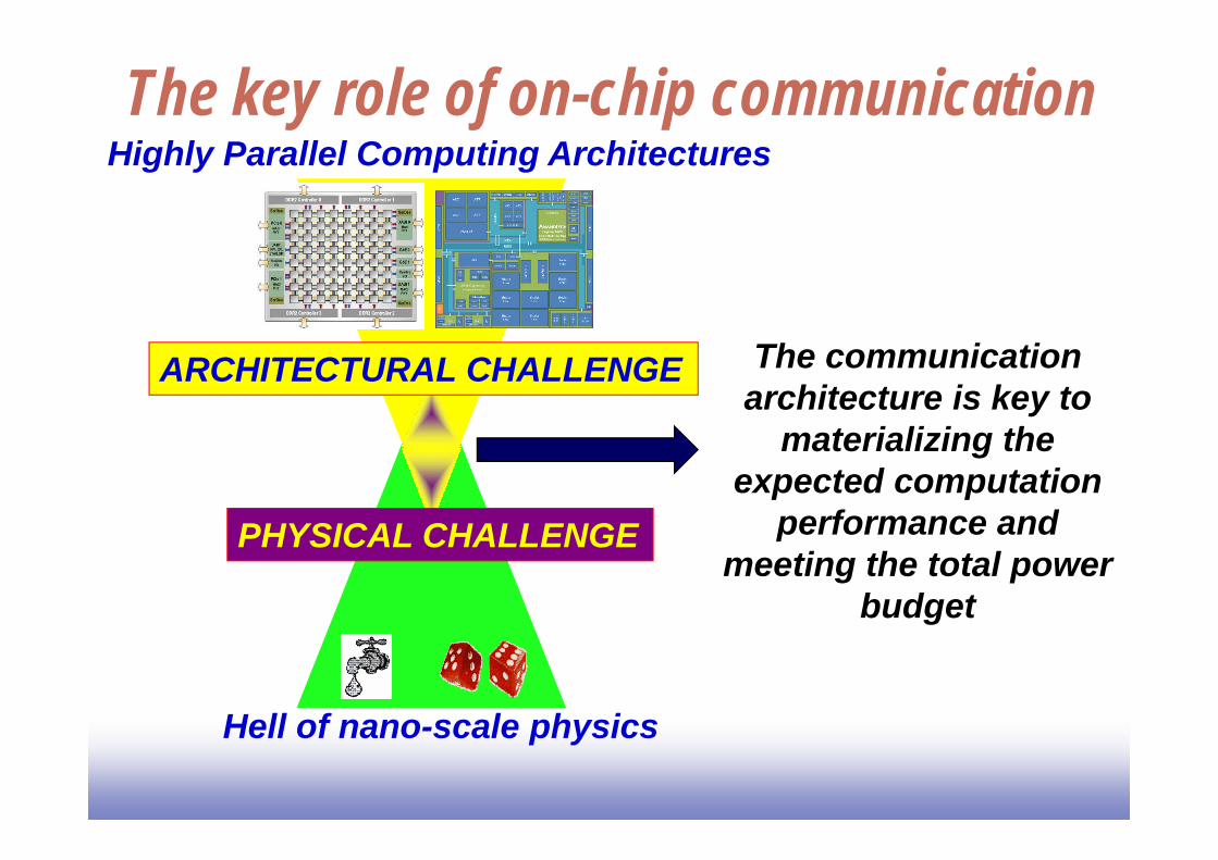
The key role of on-chip communication
ARCHITECTURAL CHALLENGE
PHYSICAL CHALLENGE
Highly Parallel Computing Architectures
Hell of nano-scale physics
The communication architecture is key to
materializing the expected computation
performance and meeting the total power
budget

The communication bottleneck Historically: Shared bus topology Aimed at simple, cost-effective integration of
components Typical example: ARM Ltd. AMBA AHB
Problems:-SERIALIZATION of bus access requests-SINGLE outstanding transaction
If wait states for memory accessare needed, everybody waits
BUS
Slave 1
CPU1
Slave 3Slave 2
Slave 4 Slave 5
Slave 1
Master 1
Slave 3
Master 2
Slave 2
Master 3
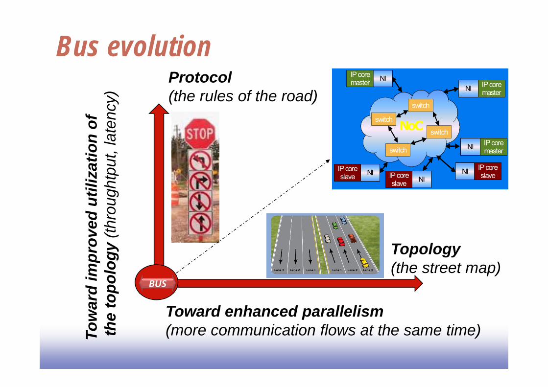
Bus evolutionProtocol (the rules of the road)
Topology(the street map)
Toward enhanced parallelism(more communication flows at the same time)To
war
d im
prov
ed u
tiliz
atio
n of
the
topo
logy
(thr
ough
tput
, lat
ency
)
BUS
IP coremasterNI
NIIP coreslave
switch
IP coremasterNI
IP coremaster NI
NIIP coreslave
NI IP coreslave
switch
switch
switch
NoC
IP coremasterNI
NIIP coreslave
switch
IP coremasterNI
IP coremaster NI
NIIP coreslave
NI IP coreslave
switch
switch
switch
NoC
IP coremasterNI IP coremasterNI
NIIP coreslave NIIP coreslave
switch
IP coremasterNI IP coremasterNI
IP coremaster NIIP coremaster NI
NIIP coreslave NIIP coreslave
NI IP coreslaveNI IP coreslave
switch
switch
switch
NoC

An «advanced» starting point The ADVANCED MICROCONTROLLER BUS
ARCHITECTURE (AMBA) BUSopen-standard, on-chip interconnect specification for the connection andmanagement of functional blocks in SoC design.
From ARM Version 1 (1996) Advanced Peripheral Bus (APB) Version 2 Advanced High-Performance Bus (AHB) Version 3 (2003): Advanced Extensible Interface (AXI) Version 4 (2010): AXI4
(2011): AXI Coherence Extensions (ACE) Version 5 (2013): Coherent Hub Interface (CHI)
These protocols are today the de facto standard for 32-bit embedded processors because they are well documented and can be used without
any royalties.
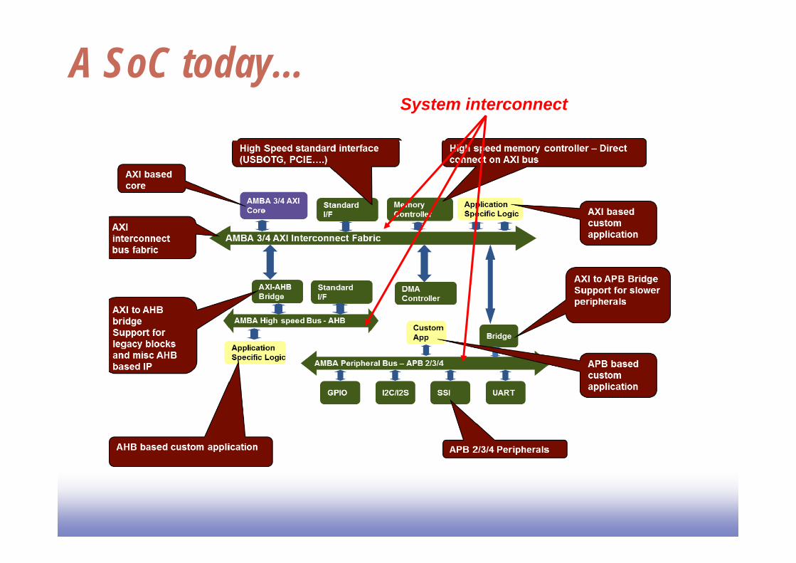
A SoC today…System interconnect
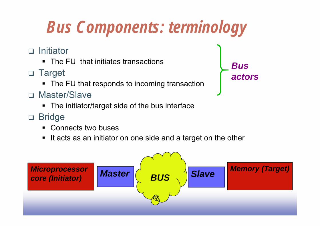
Bus Components: terminology Initiator
The FU that initiates transactions Target
The FU that responds to incoming transaction Master/Slave
The initiator/target side of the bus interface Bridge
Connects two buses It acts as an initiator on one side and a target on the other
Bus actors
Microprocessor core (Initiator) Master Memory (Target)SlaveBUS

AMBA BUS OBJECTIVES
• Facilitate the right-first-time development of multi-master and multi-slave SoCs
• Be technology independent and allow IP design reuse
• Encourage modular system design
• Minimize silicon infrastructure for on-chip communication

AMBA BUS(SES)
AHB: Advanced High Performance Bus High Performance Pipelined Operation Multiple Bus Masters Burst transfers Split transactions
APB: Advanced Peripheral Bus Low Power Latched Address and Control Simple Interface – 1 master Suitable for Many Peripherals
BR
IDG
E
UART Timer
PIOKeyPad
High performanceARM processor
High bandwidth On-chip RAM
DMA
High BandwidthExternal Memory
Interface
AHB APB
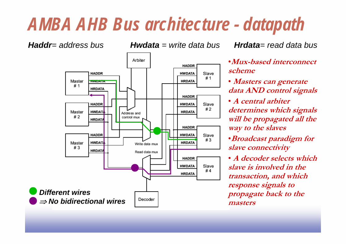
AMBA AHB Bus architecture - datapath
Different wires No bidirectional wires
Haddr= address bus Hwdata = write data bus Hrdata= read data bus
•Mux-based interconnect scheme• Masters can generate data AND control signals• A central arbiter determines which signals will be propagated all the way to the slaves•Broadcast paradigm for slave connectivity• A decoder selects which slave is involved in the transaction, and which response signals to propagate back to the masters

Address decoding
Centralized decoder. Simple (high-speed) decoding of the HADDR MSBs
Master#1
Master#2
Slave#1
Slave#2
Slave#3
Decoder
HADDR_M1[31:0]
HADDR_M2[31:0]
HADDR to all slaves
HSEL_S1HSEL_S2HSEL_S3
Address andControl mux
Shared address Bus
Dedicated control wires
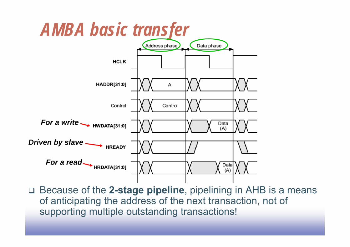
AMBA basic transfer
For a write
For a read
Because of the 2-stage pipeline, pipelining in AHB is a means of anticipating the address of the next transaction, not of supporting multiple outstanding transactions!
Driven by slave

Transfer with WAIT states
2 wait cycles
During wait states, all communication actors “wait”! …which is always a bad thing!
Next address

Bus ArbitrationBuses can support multiple initiatorsNeed a protocol for allocating bus
resources and resolving conflicts Bus arbitration protocol
Need a decision procedure to choose Arbitration policy
NOTE: Do not confuse arbitration Protocol with arbitration policy
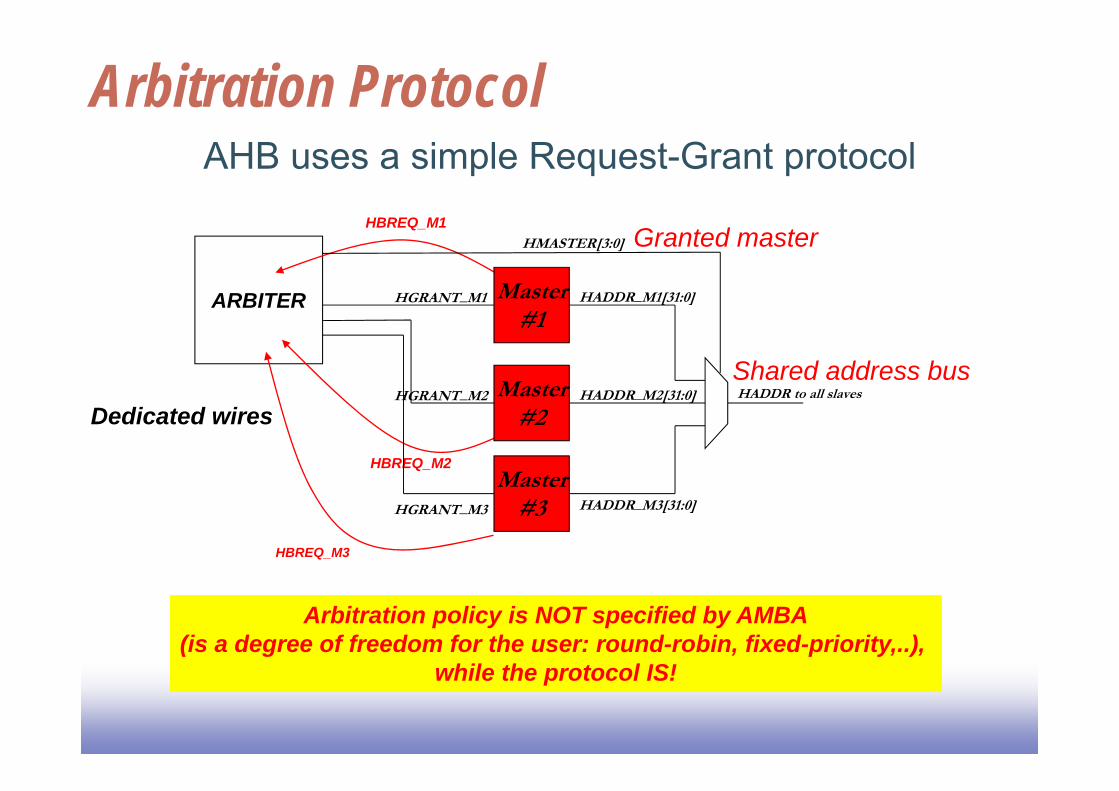
Arbitration Protocol
ARBITER
Dedicated wires
Shared address bus
Arbitration policy is NOT specified by AMBA(is a degree of freedom for the user: round-robin, fixed-priority,..),
while the protocol IS!
HBREQ_M3
HBREQ_M2
HBREQ_M1
AHB uses a simple Request-Grant protocol
Granted master
Master#1
Master#2
Master#3
HGRANT_M1
HGRANT_M2
HGRANT_M3
HADDR_M1[31:0]
HADDR_M2[31:0]
HADDR_M3[31:0]
HADDR to all slaves
HMASTER[3:0]

Granting bus accessWaiting for access
Previous data phase(transfer) completed
Bus access timeAddress phase Data phase
“Hready” dictates transaction timing
Burst transfersArbitration has a significant costBurst transfers amortize arbitration cost Grant bus control for a number of data
transfers (not for a single one) Of Help with DMA and block transfers
Requires safeguards against starvation Starvation is when a ready-to-go bus
transaction is blocked indefinitely since it cannot acquire the needed resources

AMBA AHB Burst types
Wrapping for transactions not aligned to word_size*beat
SINGLE: single transfers INCR: incremental burst of unspecified length INCRx: incremental burst of x words (beats)WRAPx: wrapping burst of x words (beats)
B
CACHE MISS(B)
L2
RESTART
Cache line
B C DL2
CPU runningA B C D
L2
CPU running

4-beat incrementing burst

Handover after burstThe arbiter changes HGRANTx signals when the penultimate (one
before last) address has been sampled. The new HGRANTx information will then be sampled at the same point as the last address of the burst
is sampled, thus giving rise to no handover overhead

Slave responsesOnce initiated, a master cannot suspend/cancel a transfer
the slave determines how the transfer should progress
The slave provides the status of the transfer through-HREADY-HRESP[0,1]signals
Advantage: if slave wait states < x (say, 16) cycles, keep the bus busy, otherwise release it and re-gain it later on.

Slave responses
Default: when master samplesHREADY high and HRESP OK,
Transfer done!
E.g.: memory protection.Write access to read-only memory location
The master should retry until it completes...but may be ungranted!Prevents starvation of high-priority masters
The master should retry the transfer when it is next granted.Prevents starvation of all masters
Error, Retry and Split are 2-cycle responses due to the pipelined nature of the bus

Slave Retry response The slave reads in the first address A, and then signals a retry response Retry is denoted by 1) Hready Low && 2) HRESP=Retry An idle cycle follows for state rollback in bus and master FSMs
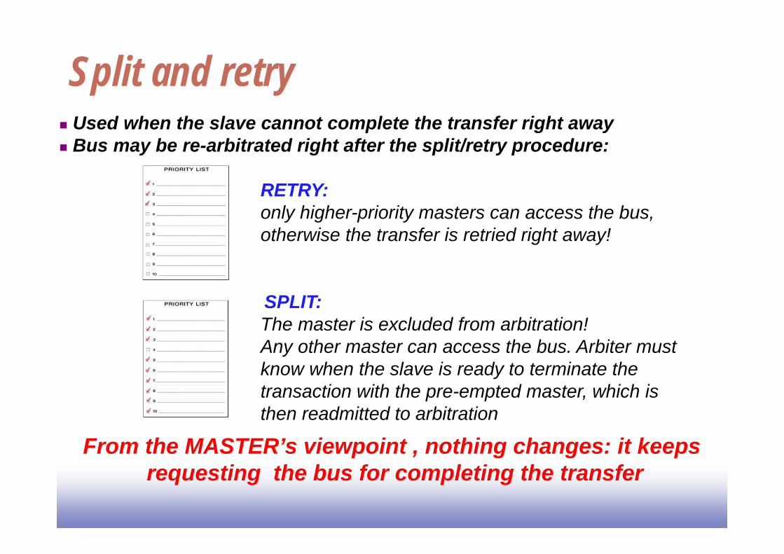
Split and retry Used when the slave cannot complete the transfer right away Bus may be re-arbitrated right after the split/retry procedure:
RETRY:only higher-priority masters can access the bus, otherwise the transfer is retried right away!
SPLIT:The master is excluded from arbitration!Any other master can access the bus. Arbiter must know when the slave is ready to terminate thetransaction with the pre-empted master, which isthen readmitted to arbitration
From the MASTER’s viewpoint , nothing changes: it keeps requesting the bus for completing the transfer

Recovery from SPLIT
slave
arbiter
When the slave is ready to complete the transfer, it notifies the arbiter which master should be regranted access to the bus
0100
HSPLIT[..]
when any bit of HSPLITx is asserted, the arbiter restores the priority of the appropriate master
Eventually the arbiter will grant the master so it can re-attempt the transfer. This may not occur immediately if a higher priority master is using the bus.
It is initiated by the slave!
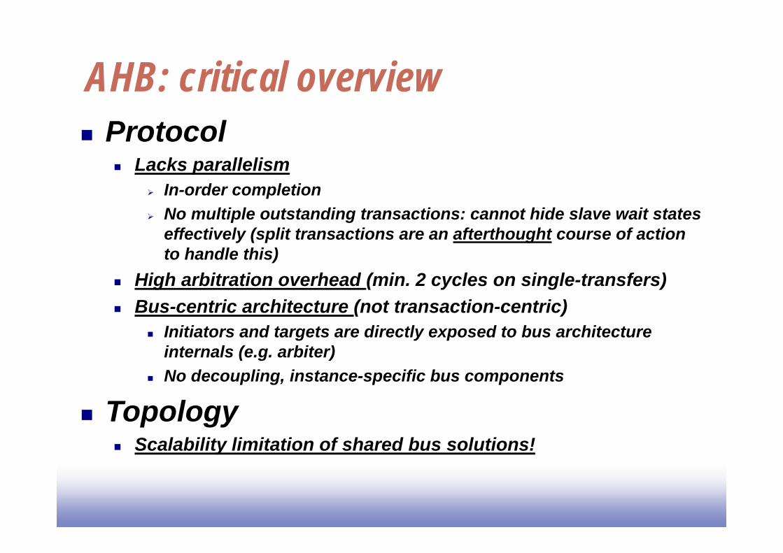
AHB: critical overview Protocol
Lacks parallelism In-order completion No multiple outstanding transactions: cannot hide slave wait states
effectively (split transactions are an afterthought course of action to handle this)
High arbitration overhead (min. 2 cycles on single-transfers) Bus-centric architecture (not transaction-centric)
Initiators and targets are directly exposed to bus architecture internals (e.g. arbiter)
No decoupling, instance-specific bus components
Topology Scalability limitation of shared bus solutions!

Bus evolution
Topology
Toward enhanced parallelism
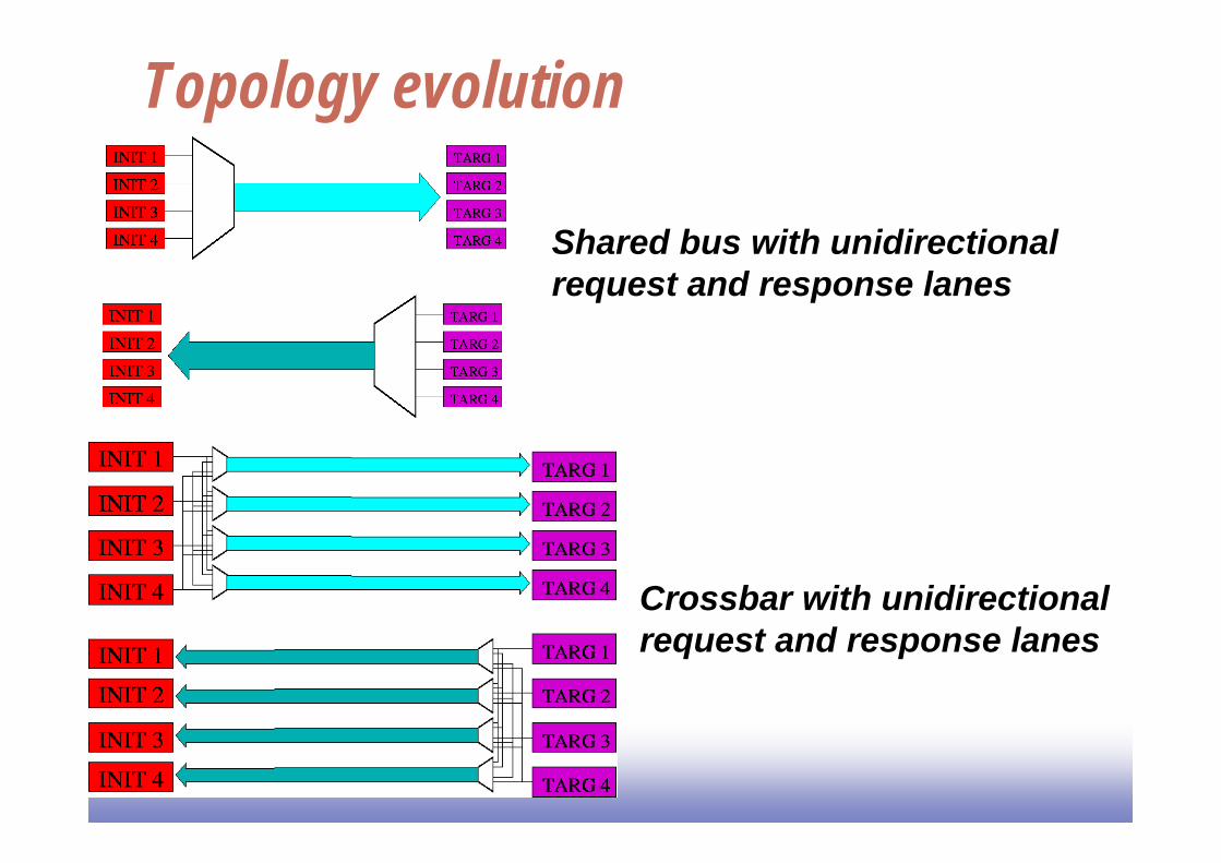
Topology evolution
Shared bus with unidirectionalrequest and response lanes
Crossbar with unidirectionalrequest and response lanes
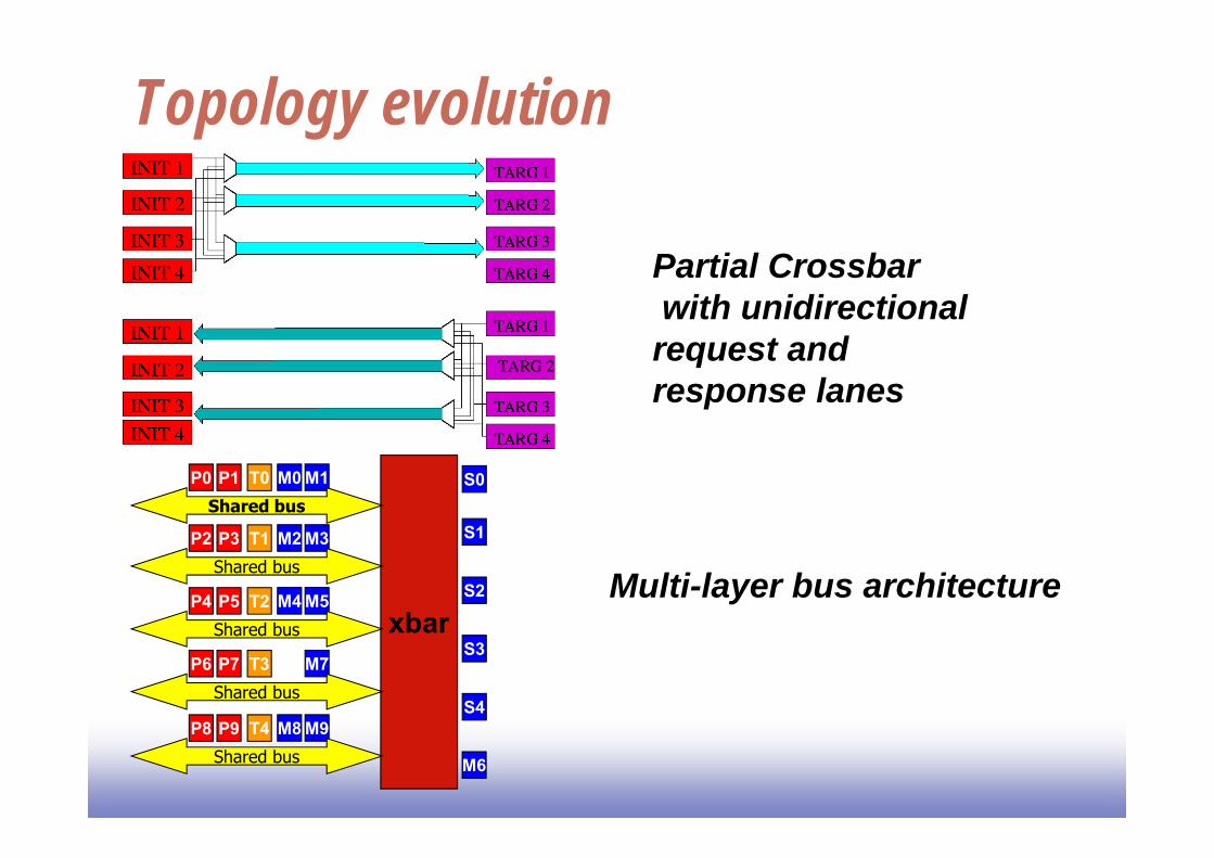
Topology evolution
Partial Crossbarwith unidirectionalrequest and response lanes
xbar
S4
S3
S2
S1
S0
M6
P0 P1 T0 M0 M1Shared bus
P2 P3 T1 M2 M3Shared bus
P4 P5 T2 M4 M5Shared bus
P6 P7 T3 M7Shared bus
P8 P9 T4 M8 M9Shared bus
Multi-layer bus architecture

But what is there on the market?

AMBA Multi-layer AHB Enables parallel access paths between multiple masters
and slaves Fully compatible with AHB wrappers It is a topology (not protocol) evolution Pure combinational matrix (scales poorly with no of I/Os)
Master1
Master2
Slave1Interconnect
Matrix
Slave1
Slave1
AHB
AHB

Multi-Layer AHB implementation The matrix is completely flexible and can be adapted MUXes are point arbitration stages AHB layer can be AHB-lite: single master, no
req/grant, no split/retry A layer is waited through the backward Hready signal
deasserted low.
HReady
HReady
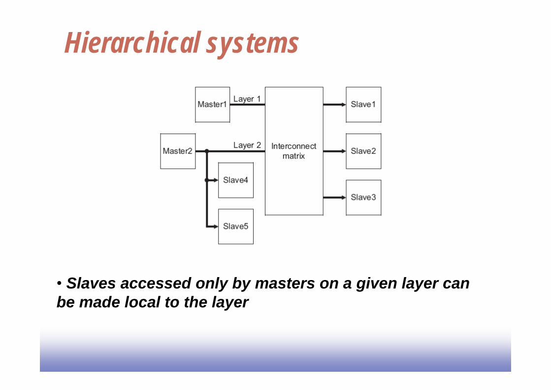
Hierarchical systems
• Slaves accessed only by masters on a given layer canbe made local to the layer
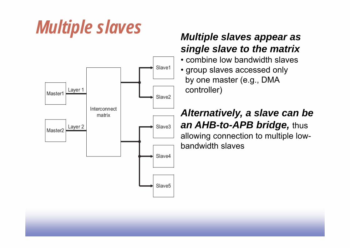
Multiple slaves Multiple slaves appear as single slave to the matrix• combine low bandwidth slaves• group slaves accessed onlyby one master (e.g., DMAcontroller)
Alternatively, a slave can be an AHB-to-APB bridge, thus allowing connection to multiple low-bandwidth slaves
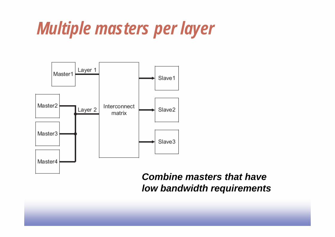
Multiple masters per layer
Combine masters that havelow bandwidth requirements

Putting it alltogether…
Interconnect matrix used for across-layercommunication
HW semaphores
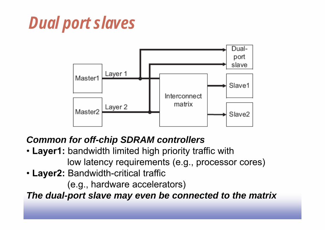
Dual port slaves
Common for off-chip SDRAM controllers• Layer1: bandwidth limited high priority traffic with
low latency requirements (e.g., processor cores)• Layer2: Bandwidth-critical traffic
(e.g., hardware accelerators)The dual-port slave may even be connected to the matrix
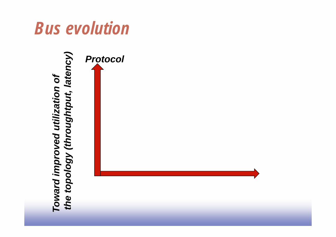
Bus evolutionProtocol
Tow
ard
impr
oved
util
izat
ion
ofth
e to
polo
gy (t
hrou
ghtp
ut, l
aten
cy)
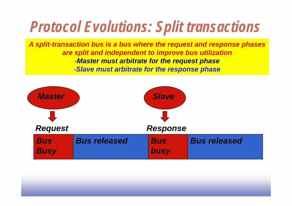
Protocol Evolutions: Split transactionsA split-transaction bus is a bus where the request and response phases
are split and independent to improve bus utilization-Master must arbitrate for the request phase-Slave must arbitrate for the response phase
Master
Request
Slave
ResponseBusBusy
Bus released Bus busy
Bus released

Multiple outstanding transactionsMaster
Requests
Queue of pendingrequests
Slave
Queue of pendingresponses
Responses
The master needs to associate each response to one of its pending requestsThe initiator should support multiple outstanding transactions too

Out-of-order completionMaster
Requests
To S2To S1
S1-slow
Queue of pendingrequests
Association between requests and responses is more challenging The typical case for out-of-order completion is when a fast slave is addressed after a slow slave. The fast slave will return its response earlier.
S2 -fast
Queue of pendingrequests
From S2
time
From S1

Out-of-order completionMaster
Requests
S12S11
S1
S11S12
Queue of pendingrequests
Out-of-order completion even in case multiple outstanding transactions are addressed to the same complex slave A complex slave may use local optimizations and change the processing order of incoming requests (e.g., serve accesses to an open row first in an SDRAM device)
Resp of S12
time
Resp of S11
anticipated

Bus-centric architectureMaster
interface
Internal bus components are directly exposed to the connected master and slave interfaces The bus architecture is instance-specific and lacks modularity
Slaveinterface
Busarchitecture

Transaction-centric bus architectureMaster interface
Internal bus components are hidden behind bus interfaces Modular architecture Internal bus architecture can freely evolve without impacting the interfaces The only objective of interfaces: specifying communication transactions! (communication abstraction)
Busarchitecture
Slave interface
Point-to-pointCommunication
Protocol
Hidden components
Slave interface
Master interface

But what is there on the market?

AMBA 3.0 (AMBA AXI)
• High bandwidth – low latency designs• High frequency operation• Flexibility in the implementation• Backward compatible with AHB and APB
Novel features with respect to AHB• Burst-based transactions with only first address issued• Address information can be issued before/after actual write data transfer
• Multiple outstanding addresses• Out-of-order transaction completion• Easy addition of register stages for timing closure
This is an evolution of the AHB communication protocol
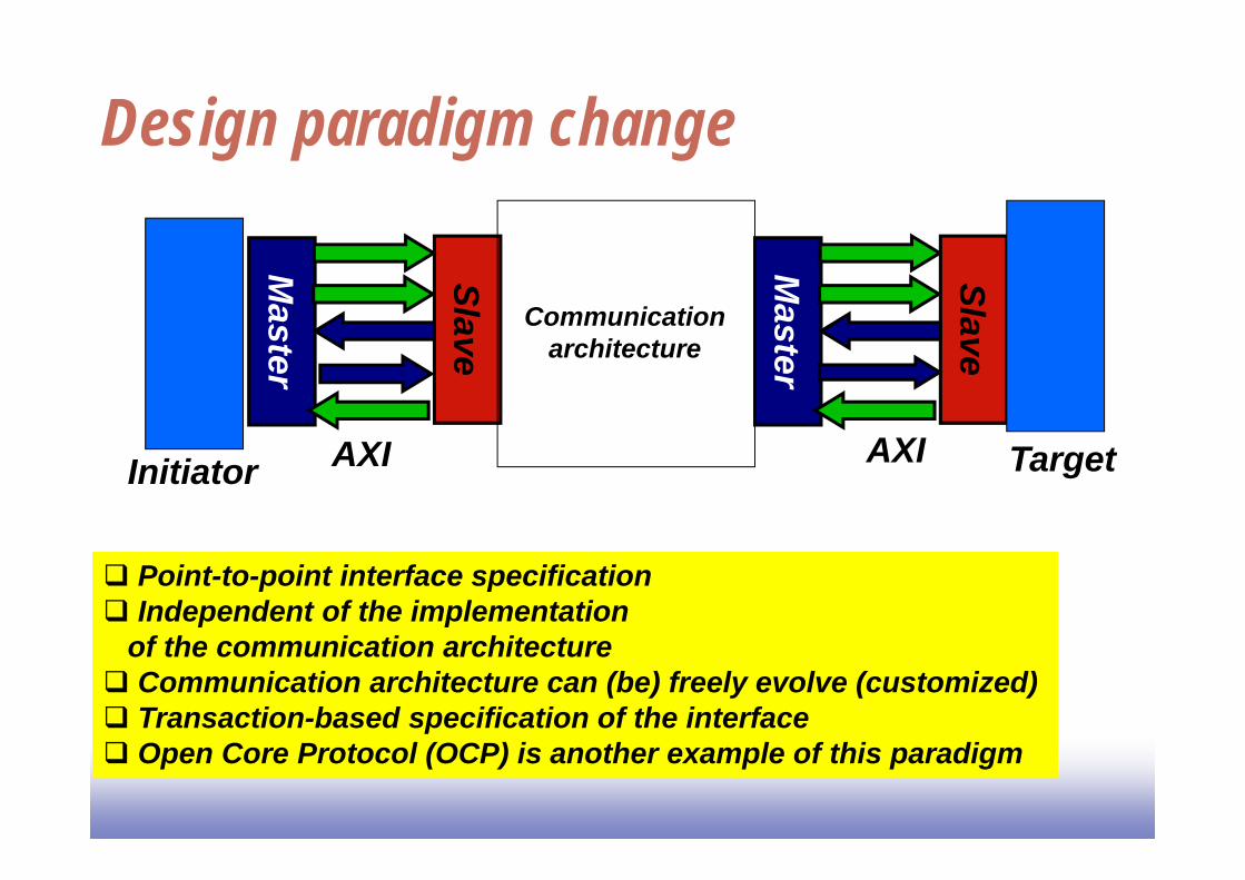
Design paradigm change
Master
Slave
Master
Slave
Initiator Target
Communicationarchitecture
Point-to-point interface specification Independent of the implementation
of the communication architecture Communication architecture can (be) freely evolve (customized) Transaction-based specification of the interface Open Core Protocol (OCP) is another example of this paradigm
AXI AXI
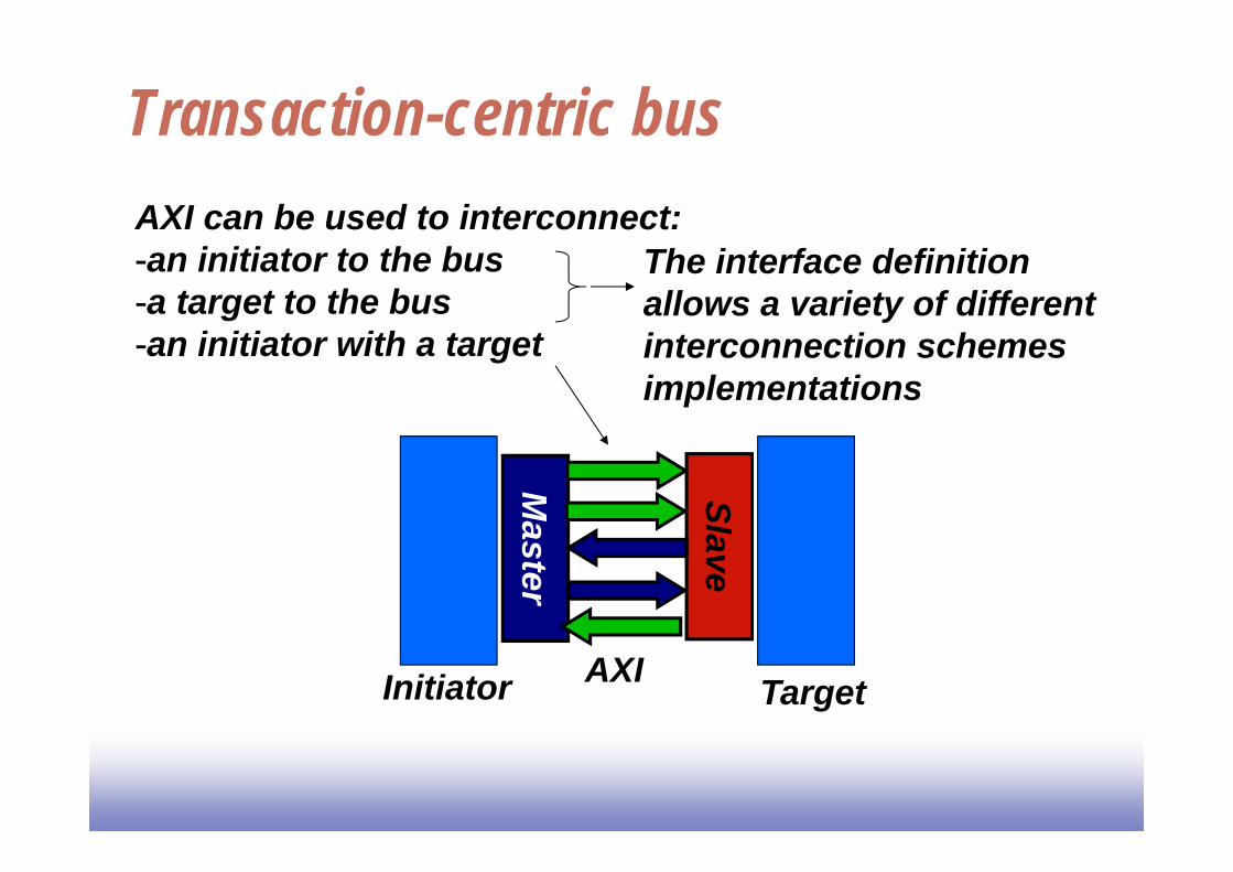
Transaction-centric bus
Master
Slave
Initiator AXI Target
AXI can be used to interconnect:-an initiator to the bus-a target to the bus-an initiator with a target
The interface definition allows a variety of different interconnection schemes implementations

Channel-based Architecture Five groups of signals (channels)
Read Address “AR” signal name prefix Read Data “R” signal name prefix Write Address “AW” signal name prefix Write Data “W” signal name prefix Write Response “B” signal name prefix
R. ADDRESS
READ DATA
WRITE DATA
RESPONSE
W. ADDRESS
Channels are independent and asynchronous wrt each other
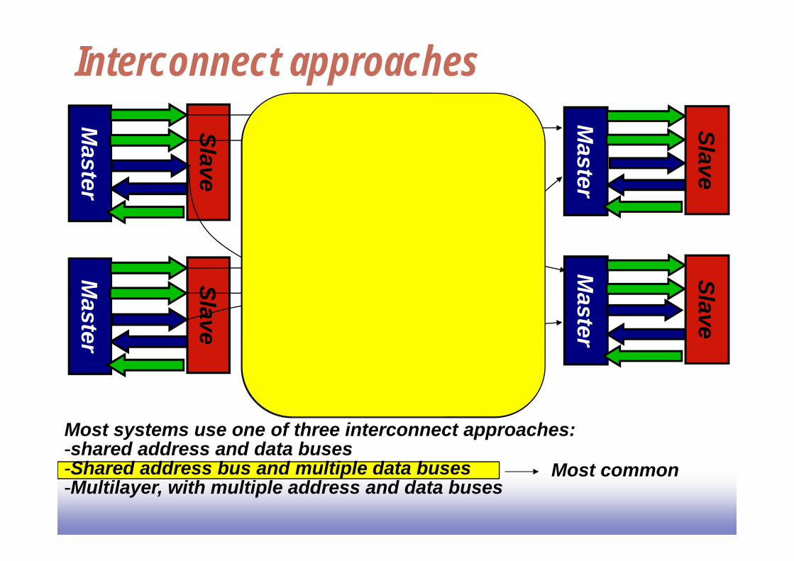
Interconnect approaches
Master
Slave
Master
Slave
Most systems use one of three interconnect approaches:-shared address and data buses-Shared address bus and multiple data buses-Multilayer, with multiple address and data buses
Most common
Master
Slave
Master
Slave
Address lane
Write Response lane
Write data lanes
Read data lanes

Read transaction
Single address for burst transfers

Write transaction
Single response for an entire burst

Channels - One way flowAWVALIDAWDDRAWLENAWSIZEAWBURSTAWLOCK
AWIDAWREADY
RVALIDRLASTRDATARRESPRIDRREADY
WVALIDWLASTWDATAWSTRBWIDWREADY
BVALIDBRESPBIDBREADY
AWPROTAWCACHE
Channel: a set of unidirectional information signals
Valid/Ready handshake mechanism READY is the only return signal Valid: source IF has valid data/control signals Ready: destination IF is ready to accept data Last: indicates last word of a burst transaction

Valid – ready handshake flexibilityAsynchronous ReadyProactive Ready
Synchronous Ready
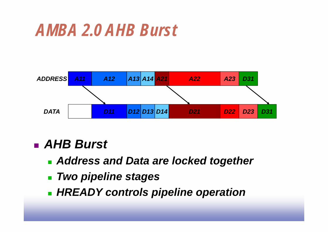
AMBA 2.0 AHB Burst
A21 A22 A23A11 A12 A13 A14
D21 D22 D23D11 D12 D13 D14
D31
D31
ADDRESS
DATA
AHB Burst Address and Data are locked together Two pipeline stages HREADY controls pipeline operation

AXI - One Address for Burst
A21A11
D21 D22 D23D11 D12 D13 D14
D31
D31
ADDRESS
DATA
AXI Burst One Address for entire burst
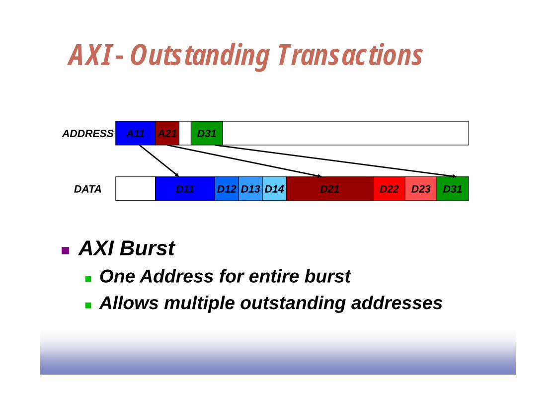
AXI - Outstanding Transactions
A21A11
D21 D22 D23D11 D12 D13 D14
D31
D31
ADDRESS
DATA
AXI Burst One Address for entire burst Allows multiple outstanding addresses

Problem: Slow slave
A21A11
D11 D12
A31ADDRESS
DATA
If one slave is very slow, all data is held up.

Out-of-Order CompletionA21A11
D21 D22 D23 D11 D12 D13 D14
D31
D31
ADDRESS
DATA
Fast slaves may return data ahead of slow slaves Complex slaves may serve requests out-of-order
Each transaction has an ID attached (given by the master IF) Channels have ID signals - AID, RID, etc. Transactions with the same ID must be ordered The interconnect in a multi-master system must appendanother tag to ID to make each master’s ID unique
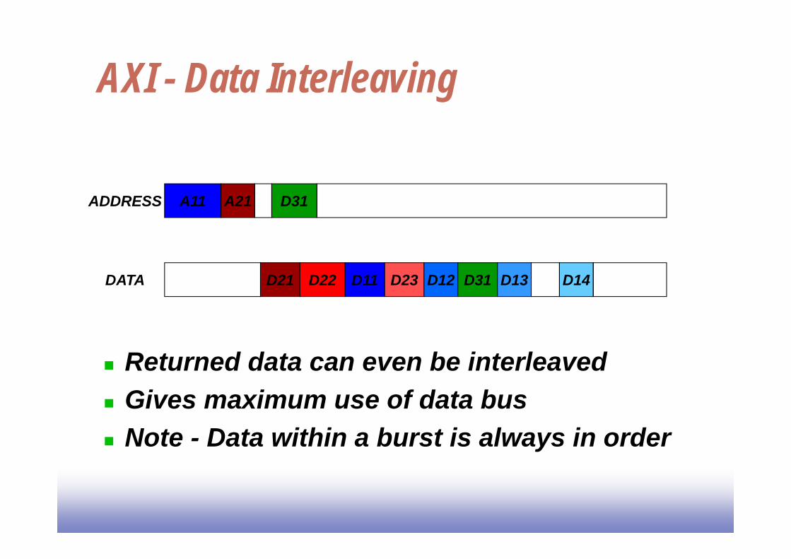
AXI - Data Interleaving
A21A11
D21 D22 D23D11 D12 D13 D14
D31
D31
ADDRESS
DATA
Returned data can even be interleaved Gives maximum use of data bus Note - Data within a burst is always in order
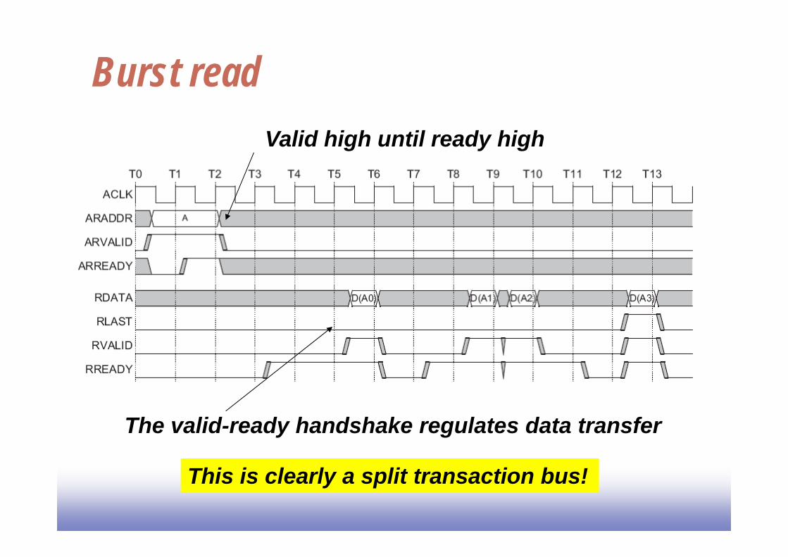
Burst readValid high until ready high
The valid-ready handshake regulates data transfer
This is clearly a split transaction bus!

Overlapping burst read
Address of second burst issued:True outstanding transactions
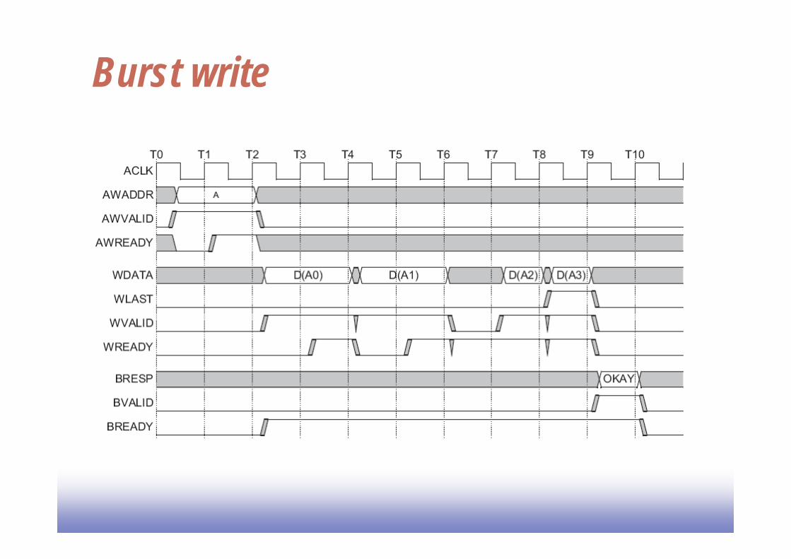
Burst write

Channels are asynchronous
Register slices canbe applied across any channel
Allows maximum frequency of operation by changing delay into latency
Register slices for max frequency
WREADY
WIDWDATAWSTRBWLAST
WVALID

Ordering restrictionsM1
M2
AXI S1
S2
Transactions from different masters have NO ordering
restrictions. They can complete in any order.
M1
M2
AXI S1
S2
ID=5ID=8 ID=5ID=8Transactions from the same master, but with different ID values, have NO ordering
restrictions. They can complete in any order.
M1
M2
AXI S1
S2
ID=5ID=5 ID=5ID=5WRITE TRANSACTIONS
Write transactions from the same master AND the same AWID must
complete in the same order the master issued the addresses in.
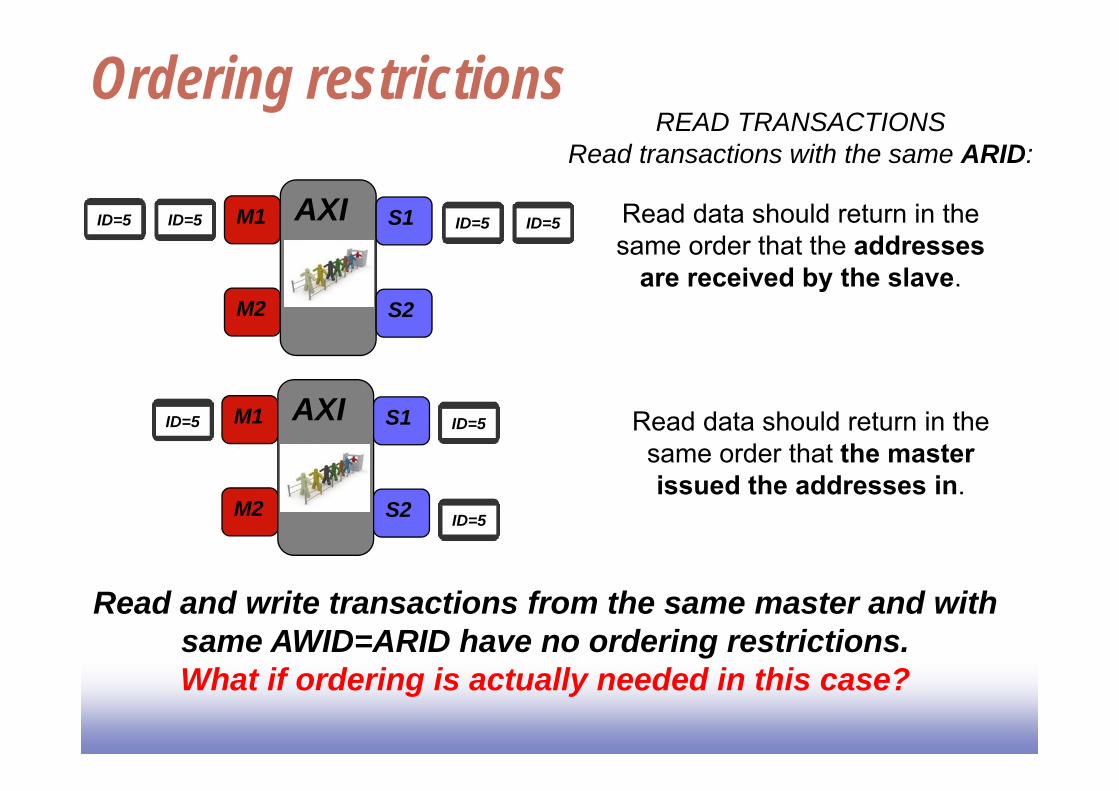
Ordering restrictionsREAD TRANSACTIONS
Read transactions with the same ARID:
M1
M2
AXI S1
S2
ID=5ID=5 ID=5ID=5 Read data should return in the same order that the addresses
are received by the slave.
M1
M2
AXI S1
S2
ID=5ID=5 Read data should return in the same order that the master issued the addresses in.
ID=5
Read and write transactions from the same master and with same AWID=ARID have no ordering restrictions. What if ordering is actually needed in this case?
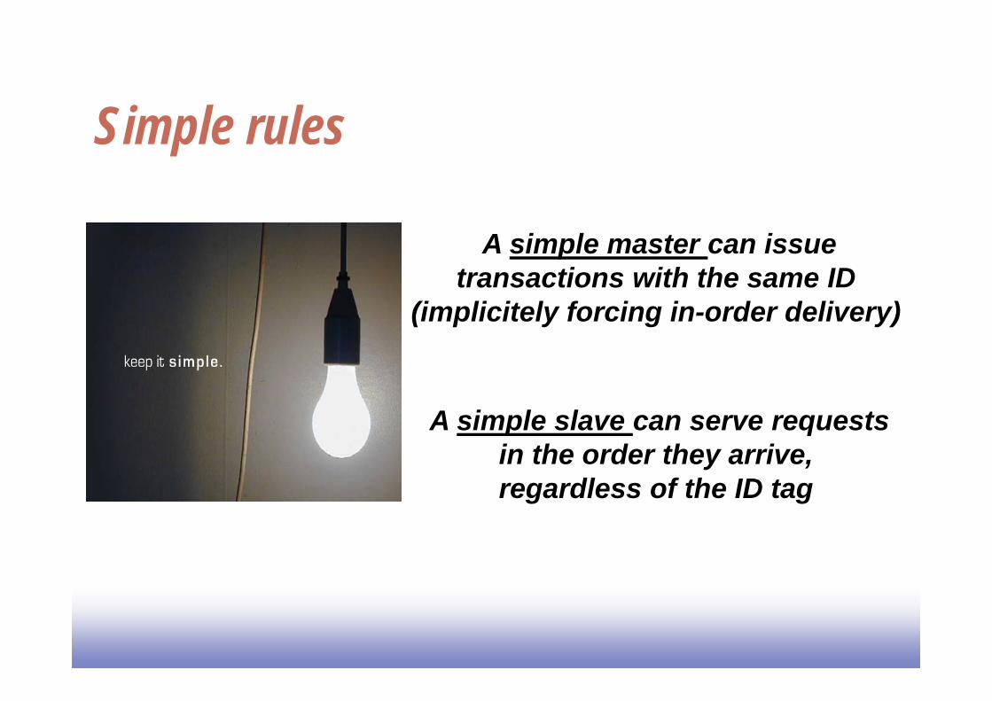
Simple rules
A simple master can issue transactions with the same ID
(implicitely forcing in-order delivery)
A simple slave can serve requests in the order they arrive,regardless of the ID tag

AMBA APB
APB: Advanced Peripheral Bus Low Power Latched Address and Control Simple Interface – 1 master Suitable for Many Peripherals
BR
IDG
E
UART Timer
PIOKeyPad
High performanceARM processor
High bandwidth On-chip RAM
DMA
High BandwidthExternal Memory
Interface
AHB APB

AHB-APB bridge
High-performance Low-power (and performance)
These are all AHB signals
CLKH
CLKL

State Diagram
When AHB (the onlymaster on the APB)wantsto drive a transfer
One cycle penalty forAPB peripheral addressdecoding
Transfer happens here
NOTE: no multi-cycle (burst) transfers, no pipelining
The APB should be used to interface to any peripherals which are low-bandwidth or do not require the high performance of a pipelined bus
interface
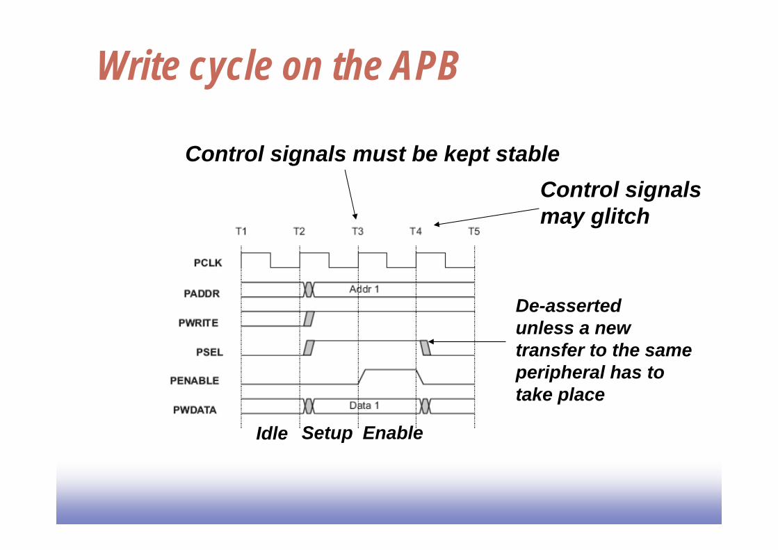
Write cycle on the APB
Idle Setup Enable
Control signals must be kept stableControl signalsmay glitch
De-assertedunless a newtransfer to the sameperipheral has to take place

Read cycle
Sampling at the endof the enable cycle

Read Cycle AHB-APB
Bridge
Bridge can DriveHREADY to stallthe transfer
Read data can beProvided only during the ENABLE cycle
Data forwardedasynchrounouslyor stored at the bridge

Burst reads on the APB
• Note address latching throughout the transfer time
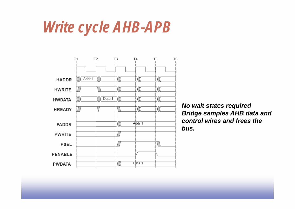
Write cycle AHB-APB
No wait states requiredBridge samples AHB data andcontrol wires and frees thebus.

Burst writes
• Wait states needed for AHB bus writes• The bridge must have 2 address registers