algorithmic_sketchbook_cecilianguyen_586596
DESCRIPTION
ÂTRANSCRIPT

1
ALGORITHMIC SKETCHBOOK

2
loftingParametric scripting

3
loftingParametric scripting
Week 1
Studying the basics in grasshopper and first lookng at some simple and useful components such as the voronoi and populate 3D components to create really interesting outcomes very easily. These can be varied from 2D to 3D forms and using sliders there is the allowance of variation which can be controlled.

4
joints Parametric scripting
Top: Exploring how you can use grasshopper in order to create these contour and sectioning lines which is useful for fabrication processes.Bottom: This also helps us to fabricate models, particularly looking at planar joints. It helps to understand Geometry, Transformations and Intersections

5
joints Parametric scripting
Week 2
Top & Bottom: These two are more complex in their forms however can be explored in grasshopper; specifically curve intersections and detailing. Looking at how the intersections can be used for detailing and documentation for fabrication purposes.

6
contours

7
contoursWeek 2
8
contoursgraph
Parametric scripting
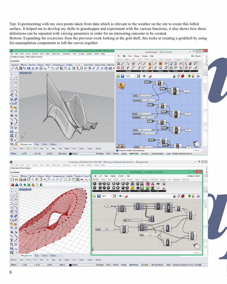
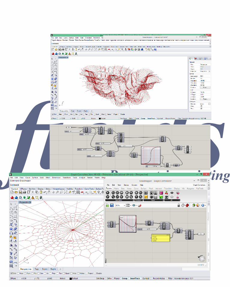
Top: Experimenting with my own points taken from data which is relevant to the weather on the site to create this lofted surface. It helped me to develop my skills in grasshopper and experiment with the various functions, it also shows how these definitions can be repeated with varying paramters in order for an interesting outcome to be created.Bottom: Expanding the excercises from the previous week looking at the grid shell, this looks at creating a gridshell by using list maniuplation components to loft the curves together.
9
contoursgraph
Parametric scripting
Week 3
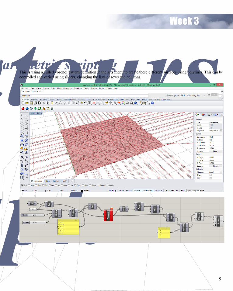
This is using a culled voronoi pattern definition in the sets menu to create these different surfaces using polylines. This can be controlled and varied using sliders, changing the lists of rows and columns.
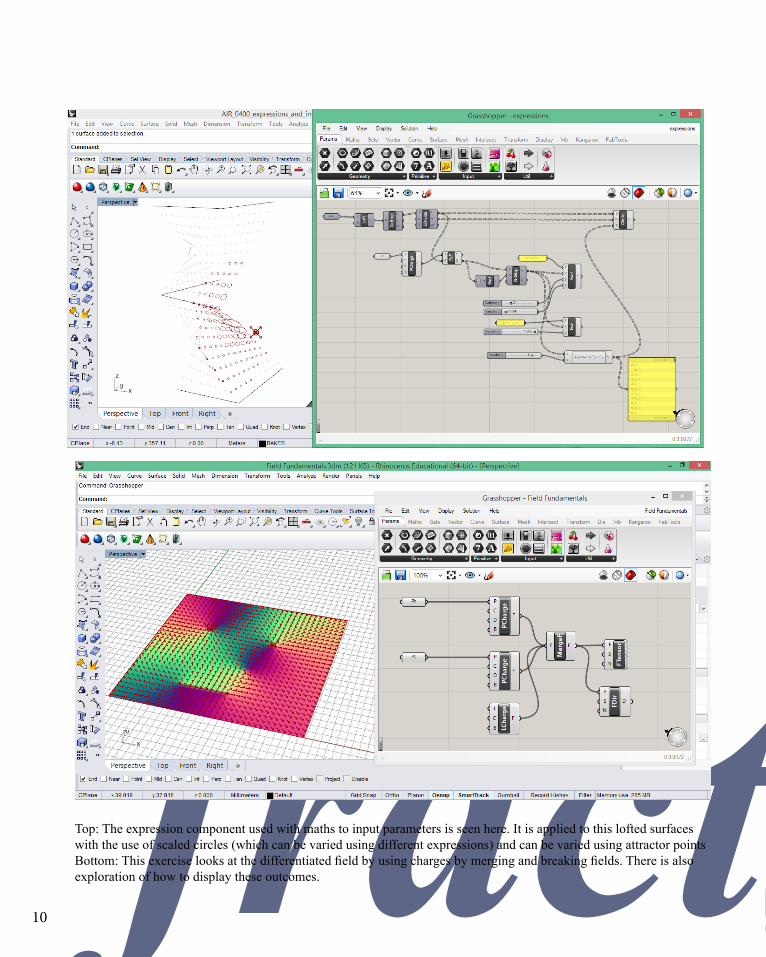
10 fractalsTop: The expression component used with maths to input parameters is seen here. It is applied to this lofted surfaces with the use of scaled circles (which can be varied using different expressions) and can be varied using attractor pointsBottom: This exercise looks at the differentiated field by using charges by merging and breaking fields. There is also exploration of how to display these outcomes.
11fractals
Week 4
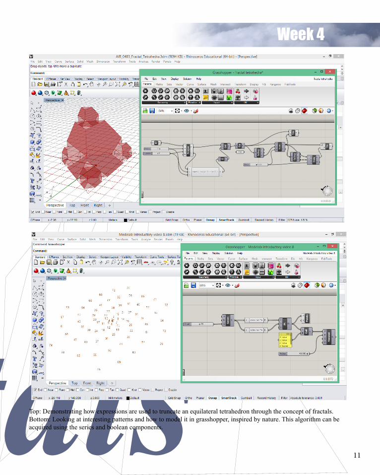
Top: Demonstrating how expressions are used to truncate an equilateral tetrahedron through the concept of fractals.Bottom: Looking at interesting patterns and how to model it in grasshopper, inspired by nature. This algorithm can be acquired using the series and boolean components.
12
fieldsParametric scripting

13
fieldsParametric scripting
Week 5
LEFT PAGETop: This looks at how fields can be utilised to reproduce a similar outcome to the Biothings project. This is done by using point chargers and curved division components to produce points and draw lines for a simliar outcome.Bottom: Using the graph mapper to generate a model which lays out a set of cells which is simliar to the ICD research pavilion. It is not exactly the same as the pavilion but it is simliar in terms of the effect it has on the aesthetics. RIGHT PAGEImage sampling component is used to generate an overlapping offset grid of apertures and imprints simliar to the Herzog de Meuron project.

14
loftingParametric scripting
Week 6
Top: Taking a look at data tree diagrams, but not building our own data tree but working within a predefined data tree. Working within those confines means that there is the exploration and navigation of the outcomes for this case using a 2D parameter space; a surface. Bottom: These look more at the tree menu and how to visualise data trees to create a multi dimensional structure. This particularly looks at more complex data trees using the shift paths component.

15
loftingWeek 7

16
iterationsThese are all outcomes of the iterations in which we were looking at specific case studies. The exploration of the morning line allowed me to learn more about how fractals and how grasshopper allows the definition to repeat in order for the these truncated geometries to recurr.

17
Week 8
iterations

18
iterationsThese are two different sets of iterations and explorations of the Voltadom and the Spanish Pavilion as part of the case studies done in Part B. Varying as many of these as possible and looking at which one can be appicable to our own designs for Part C.

19
Week 8
iterations

20
exoskeleton
1) Using rhino, circles are drawn to create the desired form (just an initial experimentation of an arch form which is similar to the NonLin Pavilion). There is consideration of the angles of these circles in order to provide the variation and increase the complexity to be as similar to the case study as possible.
2) These are referenced into grasshopper and lofted. It was proved quite difficult to recreate the “puckering” effect of the tubes at the ends of the openings, as well as the joints of the tube forms. As a result, this solution was abandoned and a different approach was attempted.
Step 1
By analyzing the idea of creating a tri-partite form and circulation pattern of the NonLin Pavilion, the current shape being re-engineered is using the “Y” form as well. Drawing out arches on rhino in this manner creates the inhabitable space in which the visitors can explore inside. The polylines are used to recreate these members and are repeated in this case as an experiment.
NonLin/Lin PavilionMarc Fornes

21
Reverse Engineering
exoskeleton
Step 2
These arches are then joined in a random manner as an attempt to create variation and increase the complexity of the form. Continuing on from here, there are added lines which extrude from the initial arches to try and create more “branches” for the tubes. For the nodes of the NonLin Pavilion to be reverse engineered there could cause problems if there are too many connections. This was taken into account and each joint would not have more than three lines connecting to ensure the joints would not be too big
Step 3
Here, the use of grasshopper and kangaroo is integral in creating this exoskeleton structure of the form. It takes the curve inputs from rhino and creates a base mesh. From the exoskeleton component, there is the opportunity to vary the sides, thickness, nodes, knuckle bumpiness and division length along the tubes. The result is a mesh which is further explored in the next step.
Step 4
Using the mesh, the forces for relation can be altered according to the nodes to create a physics simulation using the Kangaroo plugin. It uses the points around the exterior edges as anchors in order to make the interior edges into “springs”. By incorporating a slider, you can change the mesh to more or less relaxed (varying the length of the springs by the original length). By using this function, the final outcome creates a more funnel like tube which is similar to the pavilion.

22