alibi™ ip camera software user manual - supercircuits€¦ · alibi™ ip camera . software user...
TRANSCRIPT

ALIBI™ IP Camera Software User ManualProducts: ALI-IPU Series, ALI-IPV Series, ALI-IPZ Series cameras
PLEASE READ THIS MANUAL BEFORE USING YOUR CAMERAS, and always follow the instructions for safety and proper use. Save this manual for future reference.
ALI-IPU-V30xxR_CM 12/11/14
ii
CAUTION
FCC Caution: To assure continued compliance, use only shielded interface cables when connecting to computer or peripheral devices. Any changes or modifications not expressly approved by the party responsible for compliance could void the user’s authority to operate this equipment.
NOTE
This equipment has been tested and found to comply with the limits for a Class “A” digital device, pursuant to Part 15 of the FCC Rules. These limits are designed to provide reasonable protection against harmful interference when the equipment is operated in a commercial environment. This equipment generates, uses, and can radiate radio frequency energy and, if not installed and used in accordance with the instruction manual, may cause harmful interference to radio communications.
LEGAL NOTICE
Observint Technologies (Observint) products are designed to meet safety and performance standards with the use of specific Observint authorized accessories. Observint disclaims liability associated with the use of non-Observint authorized accessories.
The recording, transmission, or broadcast of any person’s voice without their consent or a court order is strictly prohibited by law.
Observint makes no representations concerning the legality of certain product applications such as the making, transmission, or recording of video and/or audio signals of others without their knowledge and/or consent. We encourage you to check and comply with all applicable local, state, and federal laws and regulations before engaging in any form of surveillance or any transmission of radio frequencies.
Alibi and the Alibi logo are trademarks of Observint.
Microsoft, Windows, and Internet Explorer are either registered trademarks or trademarks of Microsoft Corporation in the United States and/or other countries. Android is a trademark of Google Inc. Use of this trademark is subject to Google Permissions. Apple, iPhone, iPod touch, and iPad are registered trademarks of Apple Inc.
Other trademarks and trade names may be used in this document to refer to either the entities claiming the marks and names or their products. Observint disclaims any proprietary interest in trademarks and trade names other than its own.
No part of this document may be reproduced or distributed in any form or by any means without the express written permission of Observint, Inc.
© 2014 by Observint Technologies. All Rights Reserved. 11000 N. Mopac Expressway, Building 300, Austin, TX 78759 For Sales and Support, contact your distributor.
iiiALIBI™ IP Camera Software User Manual
SAFETY INSTRUCTIONS
Regulatory information
FCC information
FCC compliance: This equipment has been tested and found to comply with the limits for a digital device, pursuant to part 15 of the FCC Rules. These limits are designed to provide reasonable protection against harmful interference when the equipment is operated in a commercial environment. This equipment generates, uses, and can radiate radio frequency energy and, if not installed and used in accordance with the instruction manual, may cause harmful interference to radio communications. Operation of this equipment in a residential area is likely to cause harmful interference in which case the user will be required to correct the interference at his own expense.
FCC conditions
This device complies with part 15 of the FCC Rules. Operation is subject to the following two conditions:
1. This device may not cause harmful interference.
2. This device must accept any interference received, including interference that may cause undesired operation.
Preventive and Cautionary Tips
Before connecting and operating your cameras, please be advised of the following:
• Ensure environmental conditions meet factory specifications.• Major shocks or jolts to the unit as a result of dropping it may cause damage to the sensitive electronics within the unit.• Use the device in conjunction with an UPS if possible.
Safety Instructions
Read these instructions and keep them in a safe place for future reference.
• Please refer all work related to the installation of this product to qualified service personnel or system installers.• Do not operate the appliance outside of its specified temperature, humidity or power source ratings.• Install the unit away from heat sources such as radiators, heat registers and stoves.• Installation of the unit near consumer electronics devices, such as stereo receiver/amplifiers and televisions, is permitted as
long as the air surrounding the terminal does not exceed the above mentioned temperature range.• Handle the camera with care. Do not drop or shake, as this may damage it. • Do not use strong or abrasive detergents when cleaning the surfaces of this product. When dirt is hard to remove, use a mild
detergent and wipe gently.• Save your system configuration. • Distributing, copying, disassembling, reverse compiling, reverse engineering, and exporting, in violation of export laws, the
software provided with this product is expressly prohibited.
iv
TABLE OF CONTENTS
Table of Contents
SECTION 1 Overview . . . . . . . . . . . . . . . . . . . . . . . . . . . . . . . . . . . . . . . . . . . . . . . . . . . . . . . . . . . . . . . . . . . . . . . . . . .i1.1 Typical application configurations . . . . . . . . . . . . . . . . . . . . . . . . . . . . . . . . . . . . . . . . . . . . . . . . . . . . . . i
1.1.1 Camera is managed by an NVR . . . . . . . . . . . . . . . . . . . . . . . . . . . . . . . . . . . . . . . . . . . . . . . . . . . .21.1.2 Camera uses network device for video storage . . . . . . . . . . . . . . . . . . . . . . . . . . . . . . . . . . . . . . .21.1.3 Camera is managed by a VMS . . . . . . . . . . . . . . . . . . . . . . . . . . . . . . . . . . . . . . . . . . . . . . . . . . . . .3
1.2 PC requirements . . . . . . . . . . . . . . . . . . . . . . . . . . . . . . . . . . . . . . . . . . . . . . . . . . . . . . . . . . . . . . . . . . . . .3SECTION 2 Network Connection . . . . . . . . . . . . . . . . . . . . . . . . . . . . . . . . . . . . . . . . . . . . . . . . . . . . . . . . . . . . . . . . . 4
2.1 Locating cameras on the network - using Alibi Discover . . . . . . . . . . . . . . . . . . . . . . . . . . . . . . . . . . . .42.1.1 Restore Default Password . . . . . . . . . . . . . . . . . . . . . . . . . . . . . . . . . . . . . . . . . . . . . . . . . . . . . . . . .6
SECTION 3 Remote Access . . . . . . . . . . . . . . . . . . . . . . . . . . . . . . . . . . . . . . . . . . . . . . . . . . . . . . . . . . . . . . . . . . . . . . 73.1 Remote login . . . . . . . . . . . . . . . . . . . . . . . . . . . . . . . . . . . . . . . . . . . . . . . . . . . . . . . . . . . . . . . . . . . . . . . .73.2 Remote Live View screen . . . . . . . . . . . . . . . . . . . . . . . . . . . . . . . . . . . . . . . . . . . . . . . . . . . . . . . . . . . . .11
3.2.1 Remote Live View screen - ALI-IPV5060RP Fisheye camera . . . . . . . . . . . . . . . . . . . . . . . . . . . .133.3 Playback screen . . . . . . . . . . . . . . . . . . . . . . . . . . . . . . . . . . . . . . . . . . . . . . . . . . . . . . . . . . . . . . . . . . . . .143.4 Remote Log screen . . . . . . . . . . . . . . . . . . . . . . . . . . . . . . . . . . . . . . . . . . . . . . . . . . . . . . . . . . . . . . . . . .173.5 Remote SETUP screen . . . . . . . . . . . . . . . . . . . . . . . . . . . . . . . . . . . . . . . . . . . . . . . . . . . . . . . . . . . . . . . .18
3.5.1 Local Setup menu . . . . . . . . . . . . . . . . . . . . . . . . . . . . . . . . . . . . . . . . . . . . . . . . . . . . . . . . . . . . . .183.5.2 Camera Setup menus . . . . . . . . . . . . . . . . . . . . . . . . . . . . . . . . . . . . . . . . . . . . . . . . . . . . . . . . . . .19
SECTION 4 Camera Setup Menus . . . . . . . . . . . . . . . . . . . . . . . . . . . . . . . . . . . . . . . . . . . . . . . . . . . . . . . . . . . . . . . 204.1 System Setup menus . . . . . . . . . . . . . . . . . . . . . . . . . . . . . . . . . . . . . . . . . . . . . . . . . . . . . . . . . . . . . . . .21
4.1.1 Device Information . . . . . . . . . . . . . . . . . . . . . . . . . . . . . . . . . . . . . . . . . . . . . . . . . . . . . . . . . . . . .214.1.2 Time Settings . . . . . . . . . . . . . . . . . . . . . . . . . . . . . . . . . . . . . . . . . . . . . . . . . . . . . . . . . . . . . . . . . .214.1.3 Maintenance . . . . . . . . . . . . . . . . . . . . . . . . . . . . . . . . . . . . . . . . . . . . . . . . . . . . . . . . . . . . . . . . . . .234.1.4 DST (Daylight Savings Time) . . . . . . . . . . . . . . . . . . . . . . . . . . . . . . . . . . . . . . . . . . . . . . . . . . . . .254.1.5 Service . . . . . . . . . . . . . . . . . . . . . . . . . . . . . . . . . . . . . . . . . . . . . . . . . . . . . . . . . . . . . . . . . . . . . . .254.1.6 Fisheye Parameters (ALI-IPV5060RP camera only) . . . . . . . . . . . . . . . . . . . . . . . . . . . . . . . . . . .26
4.2 Network menus. . . . . . . . . . . . . . . . . . . . . . . . . . . . . . . . . . . . . . . . . . . . . . . . . . . . . . . . . . . . . . . . . . . . .274.2.1 TCP/IP . . . . . . . . . . . . . . . . . . . . . . . . . . . . . . . . . . . . . . . . . . . . . . . . . . . . . . . . . . . . . . . . . . . . . . . .274.2.2 Port . . . . . . . . . . . . . . . . . . . . . . . . . . . . . . . . . . . . . . . . . . . . . . . . . . . . . . . . . . . . . . . . . . . . . . . . . .284.2.3 DDNS . . . . . . . . . . . . . . . . . . . . . . . . . . . . . . . . . . . . . . . . . . . . . . . . . . . . . . . . . . . . . . . . . . . . . . . . .284.2.4 SNMP . . . . . . . . . . . . . . . . . . . . . . . . . . . . . . . . . . . . . . . . . . . . . . . . . . . . . . . . . . . . . . . . . . . . . . . . .304.2.5 802.1X . . . . . . . . . . . . . . . . . . . . . . . . . . . . . . . . . . . . . . . . . . . . . . . . . . . . . . . . . . . . . . . . . . . . . . .314.2.6 QoS . . . . . . . . . . . . . . . . . . . . . . . . . . . . . . . . . . . . . . . . . . . . . . . . . . . . . . . . . . . . . . . . . . . . . . . . . .32
vALIBI™ IP Camera Software User Manual
TABLE OF CONTENTS
4.2.7 FTP . . . . . . . . . . . . . . . . . . . . . . . . . . . . . . . . . . . . . . . . . . . . . . . . . . . . . . . . . . . . . . . . . . . . . . . . . .334.2.8 UPnP™ . . . . . . . . . . . . . . . . . . . . . . . . . . . . . . . . . . . . . . . . . . . . . . . . . . . . . . . . . . . . . . . . . . . . . . .344.2.9 Email . . . . . . . . . . . . . . . . . . . . . . . . . . . . . . . . . . . . . . . . . . . . . . . . . . . . . . . . . . . . . . . . . . . . . . . . .344.2.10 NAT . . . . . . . . . . . . . . . . . . . . . . . . . . . . . . . . . . . . . . . . . . . . . . . . . . . . . . . . . . . . . . . . . . . . . . . . . .36
4.3 Video/Audio menus . . . . . . . . . . . . . . . . . . . . . . . . . . . . . . . . . . . . . . . . . . . . . . . . . . . . . . . . . . . . . . . . .364.3.1 Video . . . . . . . . . . . . . . . . . . . . . . . . . . . . . . . . . . . . . . . . . . . . . . . . . . . . . . . . . . . . . . . . . . . . . . . . .364.3.2 ROI . . . . . . . . . . . . . . . . . . . . . . . . . . . . . . . . . . . . . . . . . . . . . . . . . . . . . . . . . . . . . . . . . . . . . . . . . . .37
4.4 PTZ menus . . . . . . . . . . . . . . . . . . . . . . . . . . . . . . . . . . . . . . . . . . . . . . . . . . . . . . . . . . . . . . . . . . . . . . . . .394.4.1 Basic menu . . . . . . . . . . . . . . . . . . . . . . . . . . . . . . . . . . . . . . . . . . . . . . . . . . . . . . . . . . . . . . . . . . . .394.4.2 Limit menu . . . . . . . . . . . . . . . . . . . . . . . . . . . . . . . . . . . . . . . . . . . . . . . . . . . . . . . . . . . . . . . . . . . .404.4.3 Initial Position menu . . . . . . . . . . . . . . . . . . . . . . . . . . . . . . . . . . . . . . . . . . . . . . . . . . . . . . . . . . . .414.4.4 Park Action menu. . . . . . . . . . . . . . . . . . . . . . . . . . . . . . . . . . . . . . . . . . . . . . . . . . . . . . . . . . . . . . .424.4.5 Privacy Mask menu . . . . . . . . . . . . . . . . . . . . . . . . . . . . . . . . . . . . . . . . . . . . . . . . . . . . . . . . . . . . .424.4.6 Scheduled Tasks menu . . . . . . . . . . . . . . . . . . . . . . . . . . . . . . . . . . . . . . . . . . . . . . . . . . . . . . . . . .434.4.7 Clear Config menu . . . . . . . . . . . . . . . . . . . . . . . . . . . . . . . . . . . . . . . . . . . . . . . . . . . . . . . . . . . . . .454.4.8 Smart Tracking menu . . . . . . . . . . . . . . . . . . . . . . . . . . . . . . . . . . . . . . . . . . . . . . . . . . . . . . . . . . .464.4.9 Prioritize PTZ menu . . . . . . . . . . . . . . . . . . . . . . . . . . . . . . . . . . . . . . . . . . . . . . . . . . . . . . . . . . . . .47
4.5 Image menus . . . . . . . . . . . . . . . . . . . . . . . . . . . . . . . . . . . . . . . . . . . . . . . . . . . . . . . . . . . . . . . . . . . . . .484.5.1 Display Settings . . . . . . . . . . . . . . . . . . . . . . . . . . . . . . . . . . . . . . . . . . . . . . . . . . . . . . . . . . . . . . . .484.5.2 OSD Settings . . . . . . . . . . . . . . . . . . . . . . . . . . . . . . . . . . . . . . . . . . . . . . . . . . . . . . . . . . . . . . . . . . .504.5.3 Text Overlay . . . . . . . . . . . . . . . . . . . . . . . . . . . . . . . . . . . . . . . . . . . . . . . . . . . . . . . . . . . . . . . . . . .504.5.4 Privacy Mask . . . . . . . . . . . . . . . . . . . . . . . . . . . . . . . . . . . . . . . . . . . . . . . . . . . . . . . . . . . . . . . . . . .51
4.6 Security menus . . . . . . . . . . . . . . . . . . . . . . . . . . . . . . . . . . . . . . . . . . . . . . . . . . . . . . . . . . . . . . . . . . . . .524.6.1 User . . . . . . . . . . . . . . . . . . . . . . . . . . . . . . . . . . . . . . . . . . . . . . . . . . . . . . . . . . . . . . . . . . . . . . . . . .524.6.2 RTSP Authentication . . . . . . . . . . . . . . . . . . . . . . . . . . . . . . . . . . . . . . . . . . . . . . . . . . . . . . . . . . . .544.6.3 Anonymous Visit . . . . . . . . . . . . . . . . . . . . . . . . . . . . . . . . . . . . . . . . . . . . . . . . . . . . . . . . . . . . . . .554.6.4 IP Address Filter . . . . . . . . . . . . . . . . . . . . . . . . . . . . . . . . . . . . . . . . . . . . . . . . . . . . . . . . . . . . . . . .55
4.7 Events menus . . . . . . . . . . . . . . . . . . . . . . . . . . . . . . . . . . . . . . . . . . . . . . . . . . . . . . . . . . . . . . . . . . . . . .574.7.1 Motion Detection . . . . . . . . . . . . . . . . . . . . . . . . . . . . . . . . . . . . . . . . . . . . . . . . . . . . . . . . . . . . . . .574.7.2 Video Tampering . . . . . . . . . . . . . . . . . . . . . . . . . . . . . . . . . . . . . . . . . . . . . . . . . . . . . . . . . . . . . . .604.7.3 Alarm Input . . . . . . . . . . . . . . . . . . . . . . . . . . . . . . . . . . . . . . . . . . . . . . . . . . . . . . . . . . . . . . . . . . .624.7.4 Alarm Output . . . . . . . . . . . . . . . . . . . . . . . . . . . . . . . . . . . . . . . . . . . . . . . . . . . . . . . . . . . . . . . . . .644.7.5 Exception . . . . . . . . . . . . . . . . . . . . . . . . . . . . . . . . . . . . . . . . . . . . . . . . . . . . . . . . . . . . . . . . . . . . .674.7.6 Traversing Virtual Plane . . . . . . . . . . . . . . . . . . . . . . . . . . . . . . . . . . . . . . . . . . . . . . . . . . . . . . . . .684.7.7 Intrusion Detection . . . . . . . . . . . . . . . . . . . . . . . . . . . . . . . . . . . . . . . . . . . . . . . . . . . . . . . . . . . . .70

vi
TABLE OF CONTENTS
4.8 Storage menus . . . . . . . . . . . . . . . . . . . . . . . . . . . . . . . . . . . . . . . . . . . . . . . . . . . . . . . . . . . . . . . . . . . . .734.8.1 Record Schedule . . . . . . . . . . . . . . . . . . . . . . . . . . . . . . . . . . . . . . . . . . . . . . . . . . . . . . . . . . . . . . . .734.8.2 Storage Management . . . . . . . . . . . . . . . . . . . . . . . . . . . . . . . . . . . . . . . . . . . . . . . . . . . . . . . . . . .754.8.3 NAS . . . . . . . . . . . . . . . . . . . . . . . . . . . . . . . . . . . . . . . . . . . . . . . . . . . . . . . . . . . . . . . . . . . . . . . . . .764.8.4 Snapshot . . . . . . . . . . . . . . . . . . . . . . . . . . . . . . . . . . . . . . . . . . . . . . . . . . . . . . . . . . . . . . . . . . . . . .79
iALIBI™ IP Camera Software User Manual
SECTION 1: OVERVIEW
SECTION1 OverviewCongratulations on purchasing your new ALIBI™ IP camera! Your camera includes the following key features:
• Megapixel CMOS progressive scan sensor• High definition video streaming• Dual-stream video support • Video stream compression using H.264 standard. • 3D-DNR noise reduction• Wide dynamic range (WDR)• Backlight compensation • IR sensors for night vision • Dual power capable - Power over Ethernet (PoE) or 12 Vdc • Weatherproof IP66 rated• Vandal proof• Mobile surveillance• PTZ functionality (ALI-IPZ models only)
1.1 Typical application configurations
Your Alibi IP can function well in many different network configurations. The most common configurations are:
• Camera is installed on an IP network and managed by a Network Video Recorder (NVR)• Camera is installed on an IP network and uses a network based storage device, such as a NAS or SMB/CIFS server, to archive
recorded video and screen captures. The camera is managed by a PC with an Internet browser. • Camera is installed on an IP network and connected directly by a PC with a Video Management System (VMS).
Since the Alibi camera is an IP based device, several other application configurations are also possible.
Important considerations
• Alibi cameras do not contain internal storage for video recording. Therefore, storage for this data must be in an external device such as an Network video Recorder (NVR), a Network Attached Storage device (NAS or SMB/CIFS device), or a PC with a Video Management System (VMS) that stores recorded video.
• Security devices on your network should be configured with static (fixed) IP addresses whenever possible. Using fixed IP addresses for these devices greatly simplifies the communication between the components of your security system.
• Alibi cameras include a web interface that enables remote access to the camera through an Internet browser such as Microsoft® Internet Explorer®, Mozilla® Firefox®, Google Chrome™, and Apple® Safari®. With this interface, you can watch live video and perform all camera configuration functions. You can also play back recorded video, download recordings, perform screen captures, and other functions. This document uses the web interface to show all functions of the camera.
2
SECTION 1: OVERVIEW
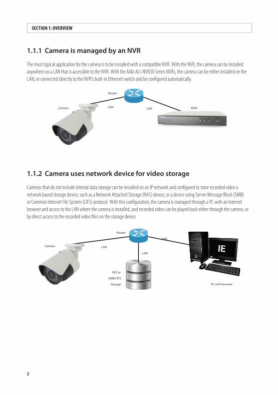
1.1.1 CameraismanagedbyanNVR
The most typical application for the camera is to be installed with a compatible NVR. With the NVR, the camera can be installed anywhere on a LAN that is accessible to the NVR. With the Alibi ALI-NVR30 Series NVRs, the camera can be either installed on the LAN, or connected directly to the NVR’s built-in Ethernet switch and be configured automatically.
Router
NVRrLAN LANCamera
1.1.2 Camerausesnetworkdeviceforvideostorage
Cameras that do not include internal data storage can be installed on an IP network and configured to store recorded video a network based storage device, such as a Network Attached Storage (NAS) device, or a device using Server Message Block (SMB) or Common Internet File System (CIFS) protocol. With this configuration, the camera is managed through a PC with an Internet browser and access to the LAN where the camera is installed, and recorded video can be played back either through the camera, or by direct access to the recorded video files on the storage device.
IECamera
NFS or
SMB/CIFS
Storage
Router
PC with browser
LAN
LAN
LAN
3ALIBI™ IP Camera Software User Manual
SECTION 1: OVERVIEW
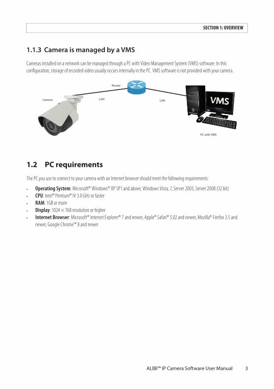
1.1.3 CameraismanagedbyaVMS
Cameras installed on a network can be managed through a PC with Video Management System (VMS) software. In this configuration, storage of recorded video usually occurs internally in the PC. VMS software is not provided with your camera.
VMSCamera
Router
PC with VMS
LAN LAN
1.2 PC requirements
The PC you use to connect to your camera with an Internet browser should meet the following requirements:
• Operating System: Microsoft® Windows® XP SP1 and above, Windows Vista, 7, Server 2003, Server 2008 (32 bit)• CPU: Intel® Pentium® IV 3.0 GHz or faster• RAM: 1GB or more• Display: 1024 × 768 resolution or higher• Internet Browser: Microsoft® Internet Explorer® 7 and newer, Apple® Safari® 5.02 and newer, Mozilla® Firefox 3.5 and
newer, Google Chrome™ 8 and newer
4
SECTION 2: NETWORK CONNECTIONS
SECTION2 Network ConnectionAlibi cameras use a standard RJ45 10/100BASE-T Ethernet interface to communicate with other devices. The Ethernet interface also supports Power over Ethernet (PoE). Whenever possible, configure the components of your security equipment on the LAN with static (fixed) IP addresses.
Cameras should be installed on the same Ethernet subnetwork (subnet) that contains the NVR or PC with VMS used to manage them, or contains a network storage device for saving recordings.
2.1 Locating cameras on the network - using Alibi Discover
The Alibi Discover Tool is used to “discover” Alibi cameras and NVRs/DVRs installed on the LAN and change their network settings. The tool is provided on the software CD with your camera.
To use the tool:
1. Insert the software CD provided with your camera into an optical drive on the Microsoft Windows computer you will use to access your camera on the LAN.
2. On the CD, find the folder that contains the Alibi Discover Tool.
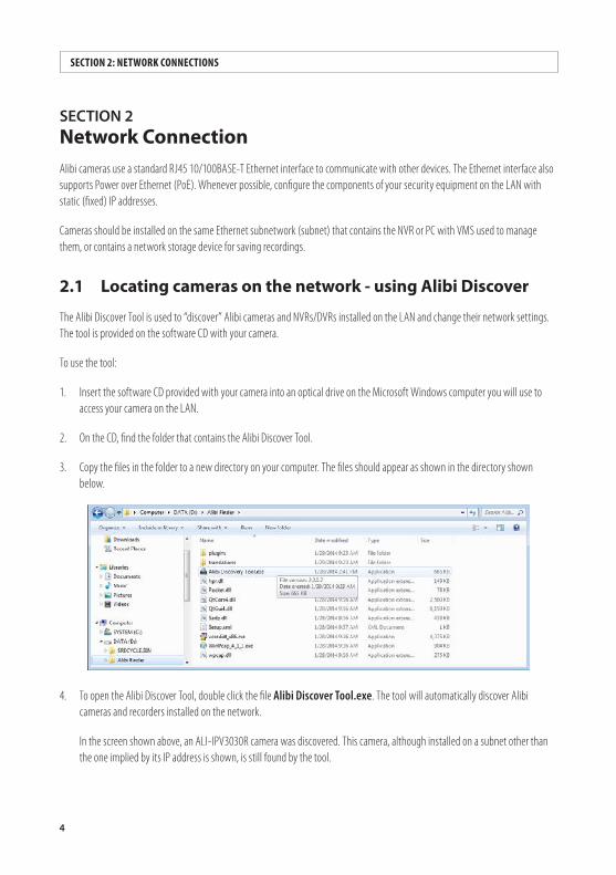
3. Copy the files in the folder to a new directory on your computer. The files should appear as shown in the directory shown below.
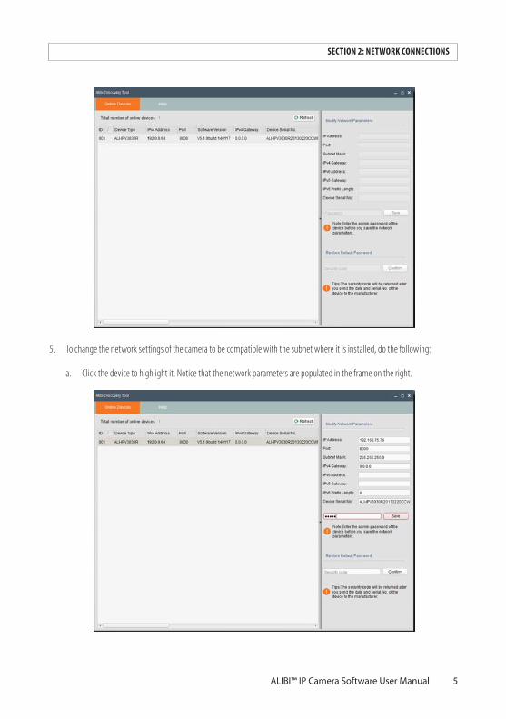
4. To open the Alibi Discover Tool, double click the file Alibi Discover Tool.exe. The tool will automatically discover Alibi cameras and recorders installed on the network.
In the screen shown above, an ALI-IPV3030R camera was discovered. This camera, although installed on a subnet other than the one implied by its IP address is shown, is still found by the tool.
5ALIBI™ IP Camera Software User Manual
SECTION 2: NETWORK CONNECTIONS
5. To change the network settings of the camera to be compatible with the subnet where it is installed, do the following:
a. Click the device to highlight it. Notice that the network parameters are populated in the frame on the right.
6
SECTION 2: NETWORK CONNECTION
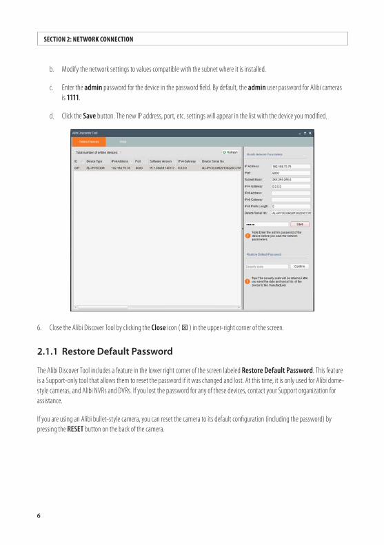
b. Modify the network settings to values compatible with the subnet where it is installed.
c. Enter the admin password for the device in the password field. By default, the admin user password for Alibi cameras is 1111.
d. Click the Save button. The new IP address, port, etc. settings will appear in the list with the device you modified.
6. Close the Alibi Discover Tool by clicking the Close icon ( T ) in the upper-right corner of the screen.
2.1.1 RestoreDefaultPassword
The Alibi Discover Tool includes a feature in the lower right corner of the screen labeled Restore Default Password. This feature is a Support-only tool that allows them to reset the password if it was changed and lost. At this time, it is only used for Alibi dome-style cameras, and Alibi NVRs and DVRs. If you lost the password for any of these devices, contact your Support organization for assistance.
If you are using an Alibi bullet-style camera, you can reset the camera to its default configuration (including the password) by pressing the RESET button on the back of the camera.
7ALIBI™ IP Camera Software User Manual
SECTION 3: REMOTE ACCESS
SECTION3 Remote AccessWhen is connected to a local network (LAN), you can access it from another computer on the LAN through Microsoft® Internet Explorer®. If using IE 10 or higher, you must configure it for “Compatibility” mode for the IP address you are logging into.
When connecting to an Alibi camera, you must enter a User Name and Password. Note that some user permissions disallow features remote access to the camera.
When logging into the camera from a remote computer for the first time, you must install a plug-in program named WebComponents. The procedure for installing the program using Internet Explorer 11 is shown below. Subsequent log ins do not require you to reinstall WebComponents.
3.1 Remote login
To access the camera from a computer on the LAN:
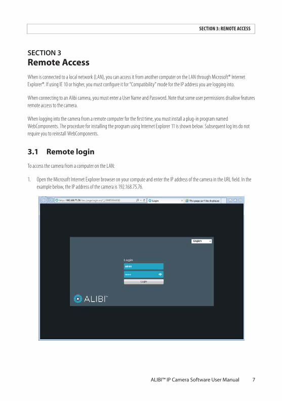
1. Open the Microsoft Internet Explorer browser on your compute and enter the IP address of the camera in the URL field. In the example below, the IP address of the camera is 192.168.75.76.
8
SECTION 3: REMOTE ACCESS
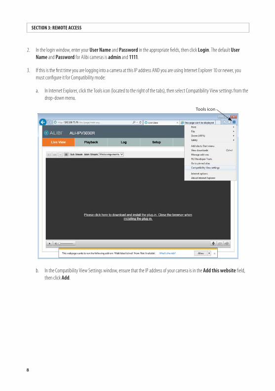
2. In the login window, enter your User Name and Password in the appropriate fields, then click Login. The default User Name and Password for Alibi cameras is admin and 1111.
3. If this is the first time you are logging into a camera at this IP address AND you are using Internet Explorer 10 or newer, you must configure it for Compatibility mode:
a. In Internet Explorer, click the Tools icon (located to the right of the tabs), then select Compatibility View settings from the drop-down menu.
Tools icon
b. In the Compatibility View Settings window, ensure that the IP address of your camera is in the Add this website field, then click Add.
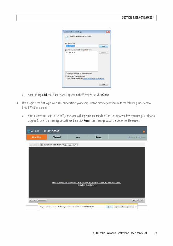
9ALIBI™ IP Camera Software User Manual
SECTION 3: REMOTE ACCESS
c. After clicking Add, the IP address will appear in the Websites list. Click Close.
4. If this login is the first login to an Alibi camera from your computer and browser, continue with the following sub-steps to install WebComponents:
a. After a successful login to the NVR, a message will appear in the middle of the Live View window requiring you to load a plug-in. Click on the message to continue, then click Run in the message box at the bottom of the screen.
10
NOTE
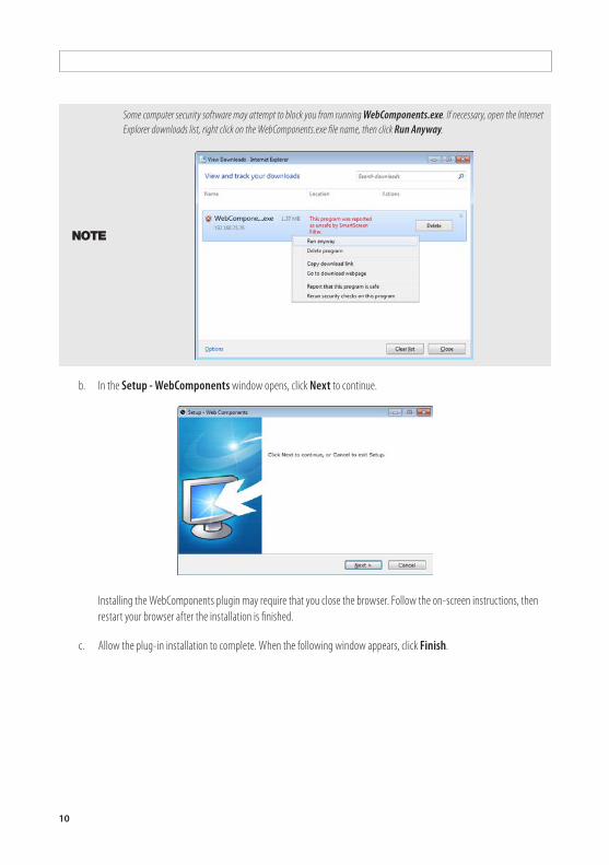
Some computer security software may attempt to block you from running WebComponents.exe. If necessary, open the Internet Explorer downloads list, right click on the WebComponents.exe file name, then click Run Anyway.
b. In the Setup - WebComponents window opens, click Next to continue.
Installing the WebComponents plugin may require that you close the browser. Follow the on-screen instructions, then restart your browser after the installation is finished.
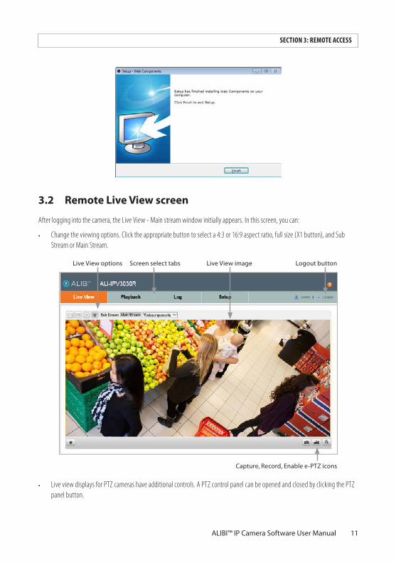
c. Allow the plug-in installation to complete. When the following window appears, click Finish.
11ALIBI™ IP Camera Software User Manual
SECTION 3: REMOTE ACCESS
3.2 Remote Live View screen
After logging into the camera, the Live View - Main stream window initially appears. In this screen, you can:
• Change the viewing options. Click the appropriate button to select a 4:3 or 16:9 aspect ratio, full size (X1 button), and Sub Stream or Main Stream.
Capture, Record, Enable e-PTZ icons
Screen select tabsLive View options Logout buttonLive View image
• Live view displays for PTZ cameras have additional controls. A PTZ control panel can be opened and closed by clicking the PTZ panel button.
12
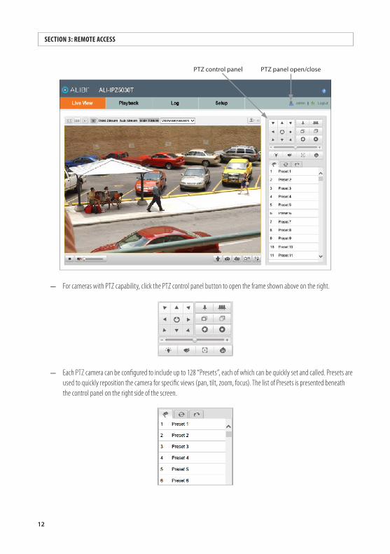
PTZ panel open/closePTZ control panel
— For cameras with PTZ capability, click the PTZ control panel button to open the frame shown above on the right.
— Each PTZ camera can be configured to include up to 128 “Presets”, each of which can be quickly set and called. Presets are used to quickly reposition the camera for specific views (pan, tilt, zoom, focus). The list of Presets is presented beneath the control panel on the right side of the screen.
SECTION 3: REMOTE ACCESS
13ALIBI™ IP Camera Software User Manual
SECTION 3: REMOTE ACCESS
• Capture the screen or start and stop recording. Captures and recordings are saved on the local HDD as configured in Local Setup menu.
• Switch from window mode to full screen mode by double clicking anywhere in the Live View video window. To return to window mode, double click anywhere.
• For cameras with Audio capability, select Mute and adjust the audio volume.
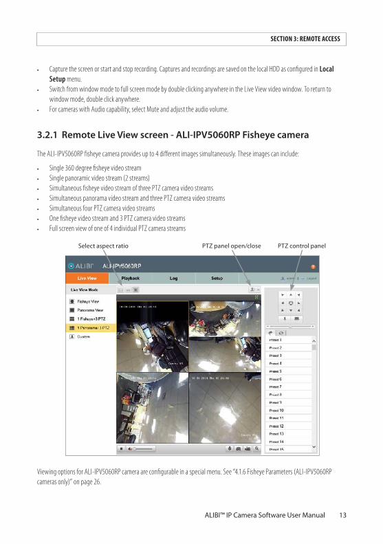
3.2.1 RemoteLiveViewscreen-ALI-IPV5060RPFisheyecamera
The ALI-IPV5060RP fisheye camera provides up to 4 different images simultaneously. These images can include:
• Single 360 degree fisheye video stream• Single panoramic video stream (2 streams)• Simultaneous fisheye video stream of three PTZ camera video streams• Simultaneous panorama video stream and three PTZ camera video streams• Simultaneous four PTZ camera video streams• One fisheye video stream and 3 PTZ camera video streams• Full screen view of one of 4 individual PTZ camera streams
PTZ panel open/closeSelect aspect ratio PTZ control panel
Viewing options for ALI-IPV5060RP camera are configurable in a special menu. See “4.1.6 Fisheye Parameters (ALI-IPV5060RP cameras only)” on page 26.
14
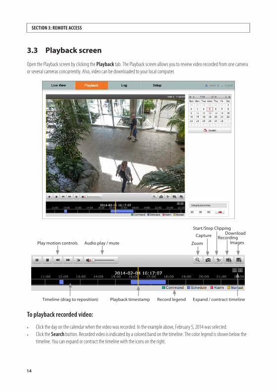
3.3 Playback screen
Open the Playback screen by clicking the Playback tab. The Playback screen allows you to review video recorded from one camera or several cameras concurrently. Also, video can be downloaded to your local computer.
RecordingDownload
Zoom
Expand / contract timeline
Play motion controls
Record legendPlayback timestamp
Capture
ImagesAudio play / mute
Timeline (drag to reposition)
Start/Stop Clipping
To playback recorded video:
• Click the day on the calendar when the video was recorded. In the example above, February 5, 2014 was selected. • Click the Search button. Recorded video is indicated by a colored band on the timeline. The color legend is shown below the
timeline. You can expand or contract the timeline with the icons on the right.
SECTION 3: REMOTE ACCESS
15ALIBI™ IP Camera Software User Manual
SECTION 3: REMOTE ACCESS
• At the bottom of the screen, drag the timeline left or right to position the video clip you want to play at the yellow Playback timestamp line.
• In the play controls, click the Play button ( u )to begin playing video. When the video is playing, the Play button changes to a Pause button ( ; ).
• Use the Audio play / mute controls to adjust the audio level (audio capable cameras only).
To save a portion of recorded video
• While playing back video, advance the playback to the beginning of the portion of the video you want to save. • Click the Start / Stop clipping icon (black scissors) . The icon will change to a Stop clipping icon (red scissors).• When the playback the end of the portion you want to save, clip the Stop clipping icon. • Playback the video clip you saved. The clip is saved to the location on your local HDD specified in the Setup (tab) | Local
Setup menu. See “3.5.1 Local Setup menu” on page 18 for more information.
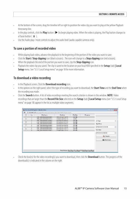
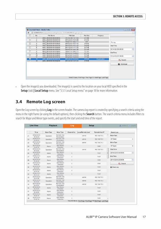
To download a video recording
• In the Playback screen, Click the Download recording icon. • In the options on the right panel, select the type of recording you want to download, the Start Time and the End Time when
the recording was made. • Click the Search button. A list of video recordings meeting the search criterion is shown in the window. NOTE: Video
recordings that are larger than the Record File Size selected on the Setup (tab) | Local Setup menu (see “3.5.1 Local Setup menu” on page 18) appear in the list as multiple video segments.
• Check the box(es) for the video recording(s) you want to download, then click the Download button. The progress of the download(s) is indicated in the column on the right.
16
SECTION 3: REMOTE ACCESS
• Playback the video recording you downloaded. The recording is saved to the location on your local HDD specified in the Setup (tab) | Local Setup menu. See “3.5.1 Local Setup menu” on page 18 for more information.
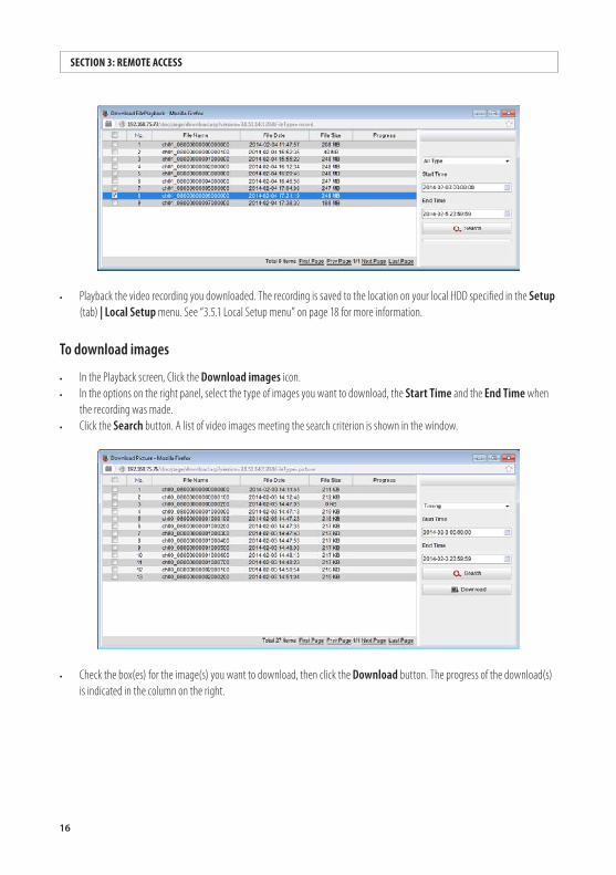
To download images
• In the Playback screen, Click the Download images icon. • In the options on the right panel, select the type of images you want to download, the Start Time and the End Time when
the recording was made. • Click the Search button. A list of video images meeting the search criterion is shown in the window.
• Check the box(es) for the image(s) you want to download, then click the Download button. The progress of the download(s) is indicated in the column on the right.
17ALIBI™ IP Camera Software User Manual
SECTION 3: REMOTE ACCESS:
• Open the image(s) you downloaded. The image(s) is saved to the location on your local HDD specified in the Setup (tab) | Local Setup menu. See “3.5.1 Local Setup menu” on page 18 for more information.
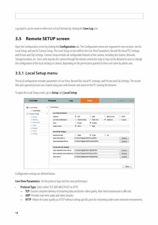
3.4 Remote Log screen
Open the Log screen by clicking Log in the screen header. The camera log report is created by specifying a search criteria using the menu in the right frame (or using the default options), then clicking the Search button. The search criteria menu includes filters to search for Major and Minor type events, and specify the start and end time of the report.
18
Log reports can be saved in either text or Excel formats by clicking the Save Log icon.
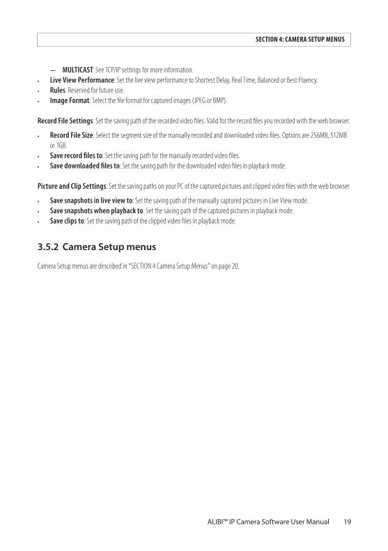
3.5 Remote SETUP screen
Open the Configuration screen by clicking the Configuration tab. The Configuration menus are organized in two sections: one for Local Setup, and one for Camera Setup. The Local Setup section defines the Live View Parameters, Record File (local PC) Settings, and Picture and Clip Settings. Camera Setup includes all configurable features of the camera, including the System, Network, Storage locations, etc. Users who log into the camera through the remote connection may or may not be allowed to view or change the configuration of the local settings or camera, depending on the permissions granted to their user name by admin user.
3.5.1 LocalSetupmenu
The local configuration includes parameters of Live View, Record Files (local PC settings), and Picture and Clip Settings. The record files and captured pictures are created using your web browser and saved on the PC running the browser.
To open the Local Setup screen, go to Setup tab | Local Setup.
Configuration settings are defined below:
Live View Parameters: Set the protocol type and live view performance.
• Protocol Type: Select either TCP, UDP, MULTICAST or HTTP.— TCP: Ensures complete delivery of streaming data and better video quality. Real-time transmission is affected.— UDP: Provides real-time audio and video streams. — HTTP: Allows the same quality as of TCP without setting specific ports for streaming under some network environments.
19ALIBI™ IP Camera Software User Manual
SECTION 4: CAMERA SETUP MENUS
— MULTICAST: See TCP/IP settings for more information. • Live View Performance: Set the live view performance to Shortest Delay, Real Time, Balanced or Best Fluency. • Rules: Reserved for future use. • Image Format: Select the file format for captured images (JPEG or BMP).
Record File Settings: Set the saving path of the recorded video files. Valid for the record files you recorded with the web browser.
• Record File Size: Select the segment size of the manually recorded and downloaded video files. Options are 256MB, 512MB or 1GB.
• Save record files to: Set the saving path for the manually recorded video files.• Save downloaded files to: Set the saving path for the downloaded video files in playback mode.
Picture and Clip Settings: Set the saving paths on your PC of the captured pictures and clipped video files with the web browser.
• Save snapshots in live view to: Set the saving path of the manually captured pictures in Live View mode.• Save snapshots when playback to: Set the saving path of the captured pictures in playback mode.• Save clips to: Set the saving path of the clipped video files in playback mode.
3.5.2 CameraSetupmenus
Camera Setup menus are described in “SECTION 4 Camera Setup Menus” on page 20.
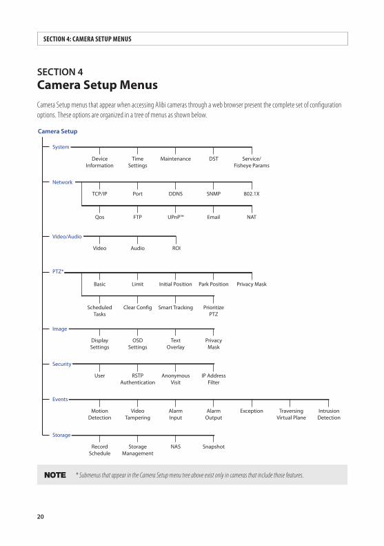
20
SECTION4 Camera Setup MenusCamera Setup menus that appear when accessing Alibi cameras through a web browser present the complete set of configuration options. These options are organized in a tree of menus as shown below.
Camera Setup
System
Network
Image
Security
MaintenanceTimeSettings
DeviceInformation
Service/Fisheye Params
DST
AnonymousVisit
RSTP Authentication
User IP AddressFilter
TextOverlay
OSDSettings
DisplaySettings
PrivacyMask
NASStorageManagement
RecordSchedule
Snapshot
Video/Audio
Audio ROIVideo
Storage
UPnP™FTPQos NATEmail
DDNSPortTCP/IP 802.1XSNMP
PTZ*
Smart TrackingClear Con�gScheduled Tasks
PrioritizePTZ
Initial PositionLimitBasic Privacy MaskPark Position
Events
AlarmInput
AlarmOutput
Exception Traversing Virtual Plane
Intrusion Detection
VideoTampering
MotionDetection
NOTE * Submenus that appear in the Camera Setup menu tree above exist only in cameras that include those features.
SECTION 4: CAMERA SETUP MENUS
21ALIBI™ IP Camera Software User Manual
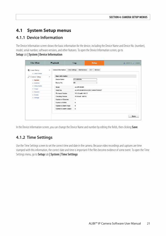
4.1 System Setup menus4.1.1 DeviceInformation
The Device Information screen shows the basic information for the device, including the Device Name and Device No. (number), model, serial number, software versions, and other features. To open the Device Information screen, go to Setup tab | System | Device Information
In the Device information screen, you can change the Device Name and number by editing the fields, then clicking Save.
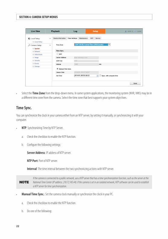
4.1.2 TimeSettings
Use the Time Settings screen to set the correct time and date in the camera. Because video recordings and captures are time stamped with this information, the correct date and time is important if the files become evidence of some event. To open the Time Settings menu, go to Setup tab | System | Time Settings
SECTION 4: CAMERA SETUP MENUS
22
• Select the Time Zone from the drop-down menu. In some system applications, the monitoring system (NVR, VMS) may be in a different time zone from the camera. Select the time zone that best supports your system objectives.
Time Sync.
You can synchronize the clock in your camera either from an NTP server, by setting it manually, or synchronizing it with your computer.
• NTP: Synchronizing Time by NTP Server.
a. Check the checkbox to enable the NTP function.
b. Configure the following settings:
Server Address: IP address of NTP server.
NTP Port: Port of NTP server.
Interval: The time interval between the two synchronizing actions with NTP server.
NOTEIf the camera is connected to a public network, use a NTP server that has a time synchronization function, such as the server at the National Time Center (IP address: 210.72.145.44). If the camera is set in an isolated network, NTP software can be used to establish a NTP server for time synchronization.
• Manual Time Sync.: Set the camera clock manually or synchronize the clock in your PC.
a. Check the checkbox to enable the NTP function.
b. Do one of the following:
SECTION 4: CAMERA SETUP MENUS
23ALIBI™ IP Camera Software User Manual
SECTION 4: CAMERA SETUP MENUS
* Enter the preferred time in the Set Time field, then click Save.* Check the Sync. with computer time box, then click Save.
NOTE After setting the time in the camera, open the DST tab to setup the Daylight Savings Time configuration for the camera.
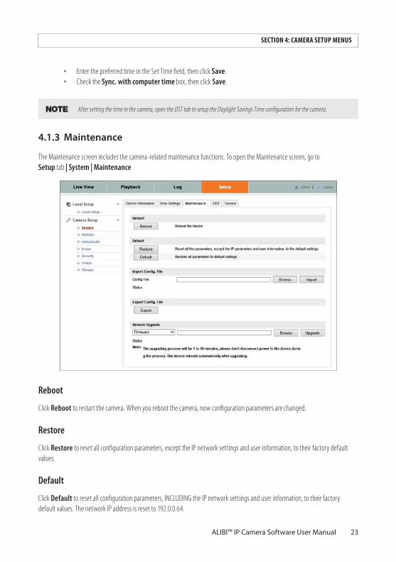
4.1.3Maintenance
The Maintenance screen includes the camera-related maintenance functions. To open the Maintenance screen, go to Setup tab | System | Maintenance
Reboot
Click Reboot to restart the camera. When you reboot the camera, now configuration parameters are changed.
Restore
Click Restore to reset all configuration parameters, except the IP network settings and user information, to their factory default values.
Default
Click Default to reset all configuration parameters, INCLUDING the IP network settings and user information, to their factory default values. The network IP address is reset to 192.0.0.64.
24
Export
Click Export to save the camera configuration file for Import later if necessary. You can also export the configuration and use it to quickly configure other cameras using the Import feature.
Import Config. File
Click Browse to locate a previously saved camera configuration file to import, then click Import. The import status is shown on the line below.
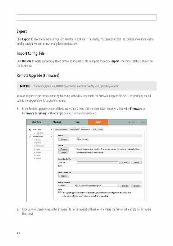
Remote Upgrade (Firmware)
NOTE Firmware upgrade should ONLY be performed if recommended by your Support organization.
You can upgrade in the camera either by browsing to the directory where the firmware upgrade file exists, or specifying the full path to the upgrade file. To upgrade firmware:
1. In the Remote Upgrade section of the Maintenance screen, click the drop-down list, then select either Firmware or Firmware Directory. In the example below, Firmware was selected.
2. Click Browse, then browse to the firmware file (for Firmware) or the directory where the firmware file exists (for Firmware Directory).
25ALIBI™ IP Camera Software User Manual
SECTION 4: CAMERA SETUP MENUS
3. Click Upgrade.
4. Wait until the upgrade process completes. (1 ~ 10 minutes), then log into your camera. (You can use the camera again when the upgrade finishes.)
5. Power off the camera.
6. Power on the camera again, then open the Device Information screen. Go to Setup tab | System | Device Information
7. Verify that the screen shows the new Firmware Version is installed.
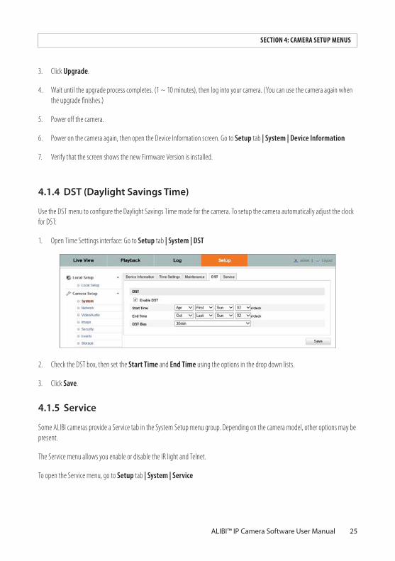
4.1.4 DST(DaylightSavingsTime)
Use the DST menu to configure the Daylight Savings Time mode for the camera. To setup the camera automatically adjust the clock for DST:
1. Open Time Settings interface: Go to Setup tab | System | DST
2. Check the DST box, then set the Start Time and End Time using the options in the drop down lists.
3. Click Save.
4.1.5 Service
Some ALIBI cameras provide a Service tab in the System Setup menu group. Depending on the camera model, other options may be present.
The Service menu allows you enable or disable the IR light and Telnet.
To open the Service menu, go to Setup tab | System | Service
26
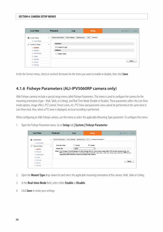
In the the Service menu, check or uncheck the boxes for the items you want to enable or disable, then click Save.
4.1.6 FisheyeParameters(ALI-IPV5060RPcameraonly)
Alibi Fisheye cameras include a special setup menu called Fisheye Parameters. This menu is used to configure the camera for the mounting orientation (type - Wall, Table, or Ceiling), and Real Time Mode (Enable or Disable). These parameters affect the Live View mode options, image effect, PTZ control, Preset scene, etc. PTZ View and panoramic view cannot be performed at the same time in Live View mod. Also, when a PTZ view is displayed, no local recording is performed.
When configuring an Alibi Fisheye camera, use this menu to select the applicable Mounting Type parameter. To configure this menu:
1. Open the Fisheye Parameter menu. Go to Setup tab | System | Fisheye Parameter
2. Open the Mount Type drop-down list and select the applicable mounting orientation of the camera: Wall, Table or Ceiling.
3. In the Real-time Mode field, select either Enable or Disable.
4. Click Save to retain your settings.
SECTION 4: CAMERA SETUP MENUS
27ALIBI™ IP Camera Software User Manual
SECTION 4: CAMERA SETUP MENUS
4.2 Network menus
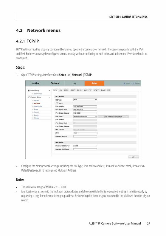
4.2.1 TCP/IP
TCP/IP settings must be properly configured before you operate the camera over network. The camera supports both the IPv4 and IPv6. Both versions may be configured simultaneously without conflicting to each other, and at least one IP version should be configured.
Steps:
1. Open TCP/IP settings interface: Go to Setup tab | Network | TCP/IP
2. Configure the basic network settings, including the NIC Type, IPv4 or IPv6 Address, IPv4 or IPv6 Subnet Mask, IPv4 or IPv6 Default Gateway, MTU settings and Multicast Address.
Notes
• The valid value range of MTU is 500 ~ 1500.• Multicast sends a stream to the multicast group address and allows multiple clients to acquire the stream simultaneously by
requesting a copy from the multicast group address. Before using this function, you must enable the Multicast function of your router.
28
3. Click Save. The camera must reboot for new settings to take effect.
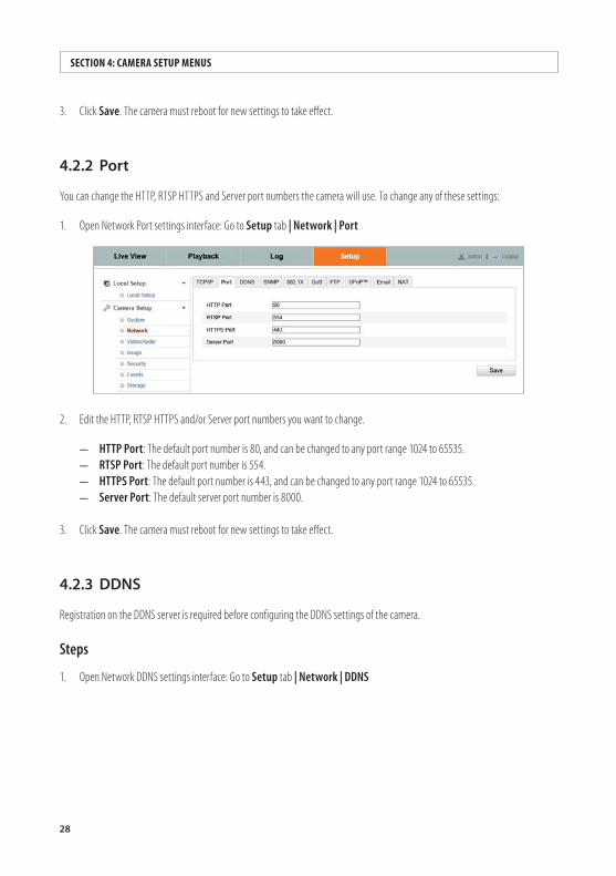
4.2.2 Port
You can change the HTTP, RTSP HTTPS and Server port numbers the camera will use. To change any of these settings:
1. Open Network Port settings interface: Go to Setup tab | Network | Port
2. Edit the HTTP, RTSP HTTPS and/or Server port numbers you want to change.
— HTTP Port: The default port number is 80, and can be changed to any port range 1024 to 65535.— RTSP Port: The default port number is 554. — HTTPS Port: The default port number is 443, and can be changed to any port range 1024 to 65535.— Server Port: The default server port number is 8000.
3. Click Save. The camera must reboot for new settings to take effect.
4.2.3 DDNS
Registration on the DDNS server is required before configuring the DDNS settings of the camera.
Steps
1. Open Network DDNS settings interface: Go to Setup tab | Network | DDNS
SECTION 4: CAMERA SETUP MENUS
29ALIBI™ IP Camera Software User Manual
SECTION 4: CAMERA SETUP MENUS
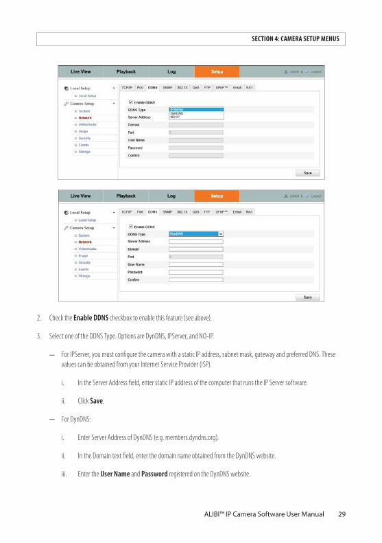
2. Check the Enable DDNS checkbox to enable this feature (see above).
3. Select one of the DDNS Type. Options are DynDNS, IPServer, and NO-IP.
— For IPServer, you must configure the camera with a static IP address, subnet mask, gateway and preferred DNS. These values can be obtained from your Internet Service Provider (ISP).
i. In the Server Address field, enter static IP address of the computer that runs the IP Server software.
ii. Click Save.
— For DynDNS:
i. Enter Server Address of DynDNS (e.g. members.dyndns.org).
ii. In the Domain text field, enter the domain name obtained from the DynDNS website.
iii. Enter the User Name and Password registered on the DynDNS website.
30
iv. Click Save.
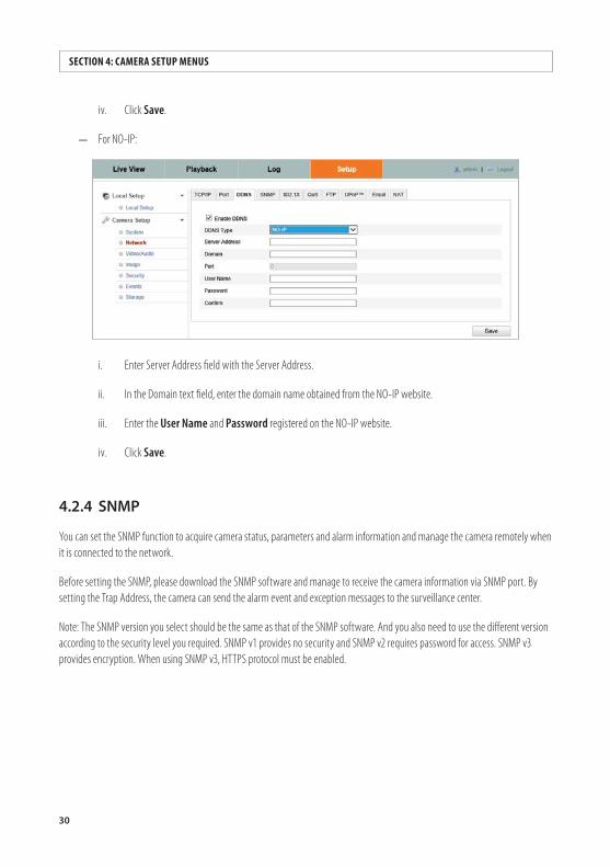
— For NO-IP:
i. Enter Server Address field with the Server Address.
ii. In the Domain text field, enter the domain name obtained from the NO-IP website.
iii. Enter the User Name and Password registered on the NO-IP website.
iv. Click Save.
4.2.4 SNMP
You can set the SNMP function to acquire camera status, parameters and alarm information and manage the camera remotely when it is connected to the network.
Before setting the SNMP, please download the SNMP software and manage to receive the camera information via SNMP port. By setting the Trap Address, the camera can send the alarm event and exception messages to the surveillance center.
Note: The SNMP version you select should be the same as that of the SNMP software. And you also need to use the different version according to the security level you required. SNMP v1 provides no security and SNMP v2 requires password for access. SNMP v3 provides encryption. When using SNMP v3, HTTPS protocol must be enabled.
SECTION 4: CAMERA SETUP MENUS
31ALIBI™ IP Camera Software User Manual
SECTION 4: CAMERA SETUP MENUS
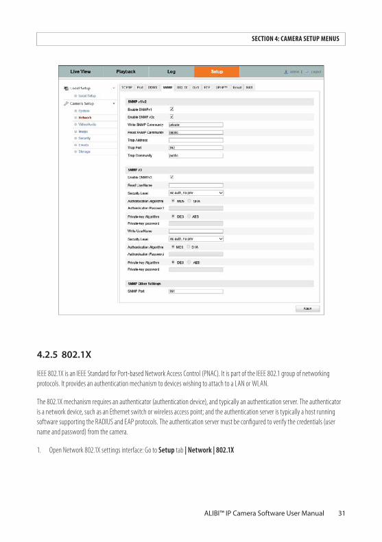
4.2.5 802.1X
IEEE 802.1X is an IEEE Standard for Port-based Network Access Control (PNAC). It is part of the IEEE 802.1 group of networking protocols. It provides an authentication mechanism to devices wishing to attach to a LAN or WLAN.
The 802.1X mechanism requires an authenticator (authentication device), and typically an authentication server. The authenticator is a network device, such as an Ethernet switch or wireless access point; and the authentication server is typically a host running software supporting the RADIUS and EAP protocols. The authentication server must be configured to verify the credentials (user name and password) from the camera.
1. Open Network 802.1X settings interface: Go to Setup tab | Network | 802.1X
32
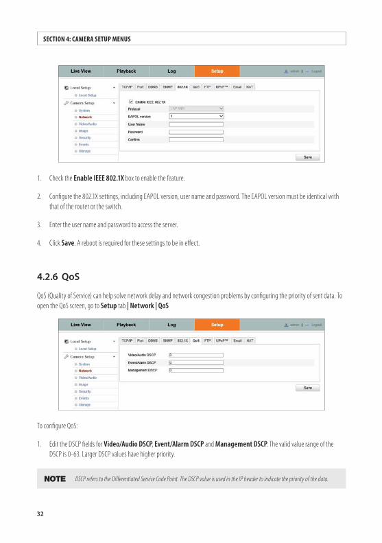
1. Check the Enable IEEE 802.1X box to enable the feature.
2. Configure the 802.1X settings, including EAPOL version, user name and password. The EAPOL version must be identical with that of the router or the switch.
3. Enter the user name and password to access the server.
4. Click Save. A reboot is required for these settings to be in effect.
4.2.6 QoS
QoS (Quality of Service) can help solve network delay and network congestion problems by configuring the priority of sent data. To open the QoS screen, go to Setup tab | Network | QoS
To configure QoS:
1. Edit the DSCP fields for Video/Audio DSCP, Event/Alarm DSCP and Management DSCP. The valid value range of the DSCP is 0-63. Larger DSCP values have higher priority.
NOTE DSCP refers to the Differentiated Service Code Point. The DSCP value is used in the IP header to indicate the priority of the data.
SECTION 4: CAMERA SETUP MENUS
33ALIBI™ IP Camera Software User Manual
SECTION 4: CAMERA SETUP MENUS
2. Click Save. The settings are applied when the camera is rebooted.
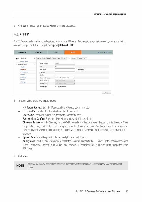
4.2.7 FTP
The FTP feature can be used to upload captured pictures to an FTP server. Picture captures can be triggered by events or a timing snapshot. To open the FTP screen, go to Setup tab | Network | FTP
1. To use FTP, enter the following parameters:
— FTP Server Address: Enter the IP address of the FTP server you want to use. — FTP server Port number. The default value of the FTP port is 21.— User Name: User name you use to authenticate access to the server. — Password and Confirm: Enter both fields with the password of the User Name. — Directory Structure: In the Directory Structure field, select the root directory, parent directory or child directory. When
the parent directory is selected, you have the option to use the Device Name, Device Number or Device IP for the name of the directory; and when the Child Directory is selected, you can use the Camera Name or Camera No. as the name of the directory.
— Upload Type: To enable uploading the captured picture to the FTP server.— Anonymous: Check the Anonymous box to enable the anonymous access to the FTP server. Use this option when access
to the FTP Server does not require a User Name and Password. The anonymous access function must be supported by the FTP server.
2. Click Save.
NOTETo upload the captured pictures to FTP server, you must enable continuous snapshot or event-triggered snapshot on Snapshot screen.
34
To upload the captured pictures to FTP server, you must select Enable Timing Snapshot or Event -Triggered Snapshot on the Setup (tab) | Storage | Snapshot screen.
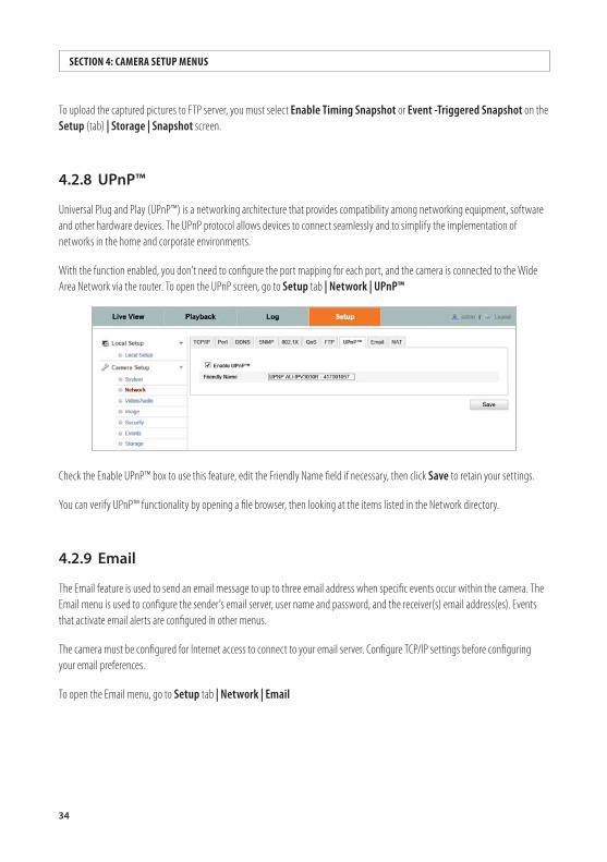
4.2.8 UPnP™
Universal Plug and Play (UPnP™) is a networking architecture that provides compatibility among networking equipment, software and other hardware devices. The UPnP protocol allows devices to connect seamlessly and to simplify the implementation of networks in the home and corporate environments.
With the function enabled, you don’t need to configure the port mapping for each port, and the camera is connected to the Wide Area Network via the router. To open the UPnP screen, go to Setup tab | Network | UPnP™
Check the Enable UPnP™ box to use this feature, edit the Friendly Name field if necessary, then click Save to retain your settings.
You can verify UPnP™ functionality by opening a file browser, then looking at the items listed in the Network directory.
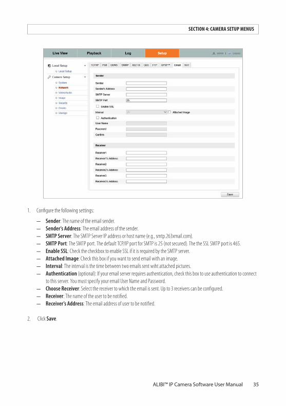
4.2.9 Email
The Email feature is used to send an email message to up to three email address when specific events occur within the camera. The Email menu is used to configure the sender’s email server, user name and password, and the receiver(s) email address(es). Events that activate email alerts are configured in other menus.
The camera must be configured for Internet access to connect to your email server. Configure TCP/IP settings before configuring your email preferences.
To open the Email menu, go to Setup tab | Network | Email
SECTION 4: CAMERA SETUP MENUS
35ALIBI™ IP Camera Software User Manual
SECTION 4: CAMERA SETUP MENUS
1. Configure the following settings:
— Sender: The name of the email sender.— Sender’s Address: The email address of the sender.— SMTP Server: The SMTP Server IP address or host name (e.g., smtp.263xmail.com). — SMTP Port: The SMTP port. The default TCP/IP port for SMTP is 25 (not secured). The the SSL SMTP port is 465.— Enable SSL: Check the checkbox to enable SSL if it is required by the SMTP server.— Attached Image: Check this box if you want to send email with an image.— Interval: The interval is the time between two emails sent wiht attached pictures. — Authentication (optional): If your email server requires authentication, check this box to use authentication to connect
to this server. You must specify your email User Name and Password.— Choose Receiver: Select the receiver to which the email is sent. Up to 3 receivers can be configured.— Receiver: The name of the user to be notified.— Receiver’s Address: The email address of user to be notified.
2. Click Save.
36
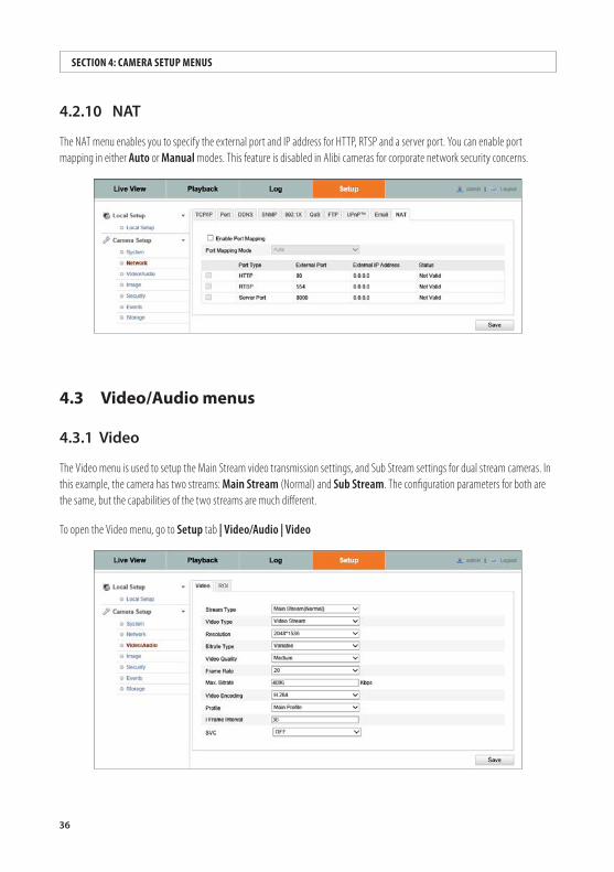
4.2.10 NAT
The NAT menu enables you to specify the external port and IP address for HTTP, RTSP and a server port. You can enable port mapping in either Auto or Manual modes. This feature is disabled in Alibi cameras for corporate network security concerns.
4.3 Video/Audio menus
4.3.1 Video
The Video menu is used to setup the Main Stream video transmission settings, and Sub Stream settings for dual stream cameras. In this example, the camera has two streams: Main Stream (Normal) and Sub Stream. The configuration parameters for both are the same, but the capabilities of the two streams are much different.
To open the Video menu, go to Setup tab | Video/Audio | Video
SECTION 4: CAMERA SETUP MENUS
37ALIBI™ IP Camera Software User Manual
SECTION 4: CAMERA SETUP MENUS
1. Select the Stream Type of the camera you want to configure. Main Stream is usually for recording and live viewing with good bandwidth, and Sub Stream should be used for live viewing when the bandwidth is limited.
2. Configure the following settings for your preferred performance:
— V ideo Type: Select the stream type to video stream or video and audio composite stream (for cameras with audio capability). For cameras with audio, the audio signal is recorded only when the Video Type is Video & Audio.
— Resolution: Select the resolution of the video output.— Bitrate Type: Select either Constant or Variable.— Video Quality: When bitrate type is selected as Variable, you can select one of six levels of video quality. Higher video
quality requires more network bandwidth. — Frame Rate: Set the frame rate to 1/16 ~ 25 fps. The frame rate is the rate at which video frames the are sent to the
receiving device, or the rate at which the video stream is recorded. A higher frame rate produces a smother image with higher quality throughout, but requires more network bandwidth.
— Max. Bitrate: Set the maximum bitrate to 32 ~ 16384 Kbps. The higher value corresponds to the higher video quality at a cost of higher network bandwidth.
— Video Encoding: When the Stream Type of the camera is Main Stream, the Video Encoding standard can be set to H.264. When the Stream Type of the camera is Sub Stream, the Video Encoding standard can be set to H.264 or MJPEG.
— Profile: The profile for this camera is Main Profile. No other profiles are selectable. — I Frame Interval: Set the I-Frame interval to 1~400. The I-frame interval represents the rate at which the entire video
frame is transmitted (refreshed) when using a video compression technology such as H.264. — SVC: Scalable video coding is an extension of the H.264/AVC standard. The technology encodes the video signal with
layers; the basic layer and several enhanced layers and it is adaptive to the network condition to transfer different video streams. For example, when the bandwidth is limited, only the basic layer data is encoded and transferred. You can enable the function when you want to see the video with several terminals, such as the mobile phone with 3G network, or the personal computer with IP network.
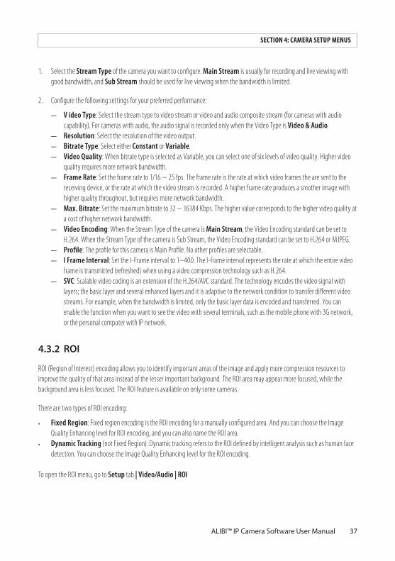
4.3.2 ROI
ROI (Region of Interest) encoding allows you to identify important areas of the image and apply more compression resources to improve the quality of that area instead of the lesser important background. The ROI area may appear more focused, while the background area is less focused. The ROI feature is available on only some cameras.
There are two types of ROI encoding:
• Fixed Region: Fixed region encoding is the ROI encoding for a manually configured area. And you can choose the Image Quality Enhancing level for ROI encoding, and you can also name the ROI area.
• Dynamic Tracking (not Fixed Region): Dynamic tracking refers to the ROI defined by intelligent analysis such as human face detection. You can choose the Image Quality Enhancing level for the ROI encoding.
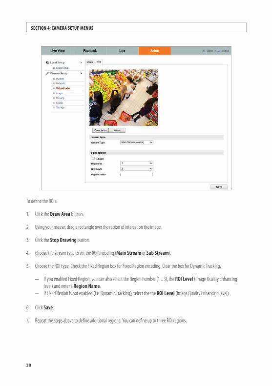
To open the ROI menu, go to Setup tab | Video/Audio | ROI
38
To define the ROIs:
1. Click the Draw Area button.
2. Using your mouse, drag a rectangle over the region of interest on the image.
3. Click the Stop Drawing button.
4. Choose the stream type to set the ROI encoding (Main Stream or Sub Stream).
5. Choose the ROI type. Check the Fixed Region box for Fixed Region encoding. Clear the box for Dynamic Tracking.
— If you enabled Fixed Region, you can also select the Region number (1 .. 3), the ROI Level (Image Quality Enhancing level) and enter a Region Name.
— If Fixed Region is not enabled (i.e. Dynamic Tracking), select the the ROI Level (Image Quality Enhancing level).
6. Click Save.
7. Repeat the steps above to define additional regions. You can define up to three ROI regions.
SECTION 4: CAMERA SETUP MENUS
39ALIBI™ IP Camera Software User Manual
SECTION 4: CAMERA SETUP MENUS
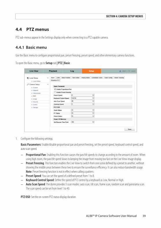
4.4 PTZ menus
PTZ sub-menus appear in the Settings display only when connecting to a PTZ capable camera.
4.4.1 Basicmenu
Use the Basic menu to configure proportional pan, preset freezing, preset speed, and other elementary camera functions.
To open the Basic menu, go to Setup tab | PTZ | Basic
1. Configure the following settings:
Basic Parameters: Enable/disable proportional pan and preset freezing, set the preset speed, keyboard control speed, and auto scan speed.
— Proportional Pan: Enabling this function causes the pan/tilt speeds to change according to the amount of zoom. When using high zoom, the pan/tilt speed slows to keeping the image from moving too fast on the Live View image display.
— Preset Freezing: This function enables the Live View to switch from one scene defined by a preset to another, without showing the middle areas between these two to ensure the surveillance efficiency. It can also reduce bandwidth usage. Note: Preset freezing function is not in effect when calling a pattern.
— Preset Speed: You can set the speed of a defined preset from 1 to 8.— Keyboard Control Speed: Define the speed of PTZ control by a keyboard as Low, Normal or High.— Auto Scan Speed: The dome provides 5 scan modes: auto scan, tilt scan, frame scan, random scan and panorama scan.
The scan speed can be set from level 1 to 40.
PTZ OSD: Set the on-screen PTZ status display duration.
40
— Zoom Status: Set the OSD zooming status duration to 2 seconds, 5 seconds, 10 seconds, Always Close or Always Open.— PT Status: Set the azimuth angle display duration while panning and tilting to 2 seconds, 5 seconds, 10 seconds, Always
Close or Always Open.— Preset Status: Set the preset name display duration while calling the preset as 2 seconds, 5 seconds, 10 seconds,
Always Close or Always Open.
Power-off Memory: When the camera restarts after a power off, it can resume the previous PTZ status or actions it was performing a specified time period before the power-off. You can set it to resume the status or actions it was performing 30 seconds, 60 seconds, 300 seconds or 600 seconds before power-off.
2. Click Save to save your settings.
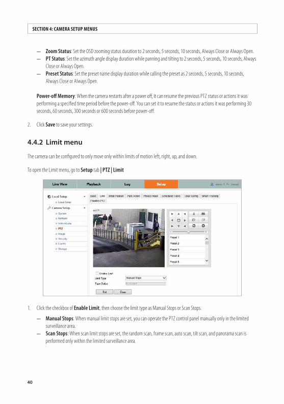
4.4.2 Limitmenu
The camera can be configured to only move only within limits of motion left, right, up, and down.
To open the Limit menu, go to Setup tab | PTZ | Limit
1. Click the checkbox of Enable Limit, then choose the limit type as Manual Stops or Scan Stops.
— Manual Stops: When manual limit stops are set, you can operate the PTZ control panel manually only in the limited surveillance area.
— Scan Stops: When scan limit stops are set, the random scan, frame scan, auto scan, tilt scan, and panorama scan is performed only within the limited surveillance area.
SECTION 4: CAMERA SETUP MENUS
41ALIBI™ IP Camera Software User Manual
SECTION 4: CAMERA SETUP MENUS
NOTESet the Manual Stops limits before setting Scan Stops limits. When you set these two limit types at the same time, Manual Stops is valid and Scan Stops is invalid.
2. Click the PTZ control buttons to determine the left/right/up/down limit stops; you can also call the defined presets and set them as the limits of the dome.
3. Click Set to save the limit stops, or click Clear to clear the limit stops.
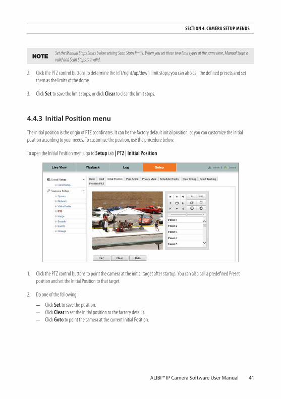
4.4.3 InitialPositionmenu
The initial position is the origin of PTZ coordinates. It can be the factory default initial position, or you can customize the initial position according to your needs. To customize the position, use the procedure below.
To open the Initial Position menu, go to Setup tab | PTZ | Initial Position
1. Click the PTZ control buttons to point the camera at the initial target after startup. You can also call a predefined Preset position and set the Initial Position to that target.
2. Do one of the following:
— Click Set to save the position. — Click Clear to set the initial position to the factory default. — Click Goto to point the camera at the current Initial Position.
42
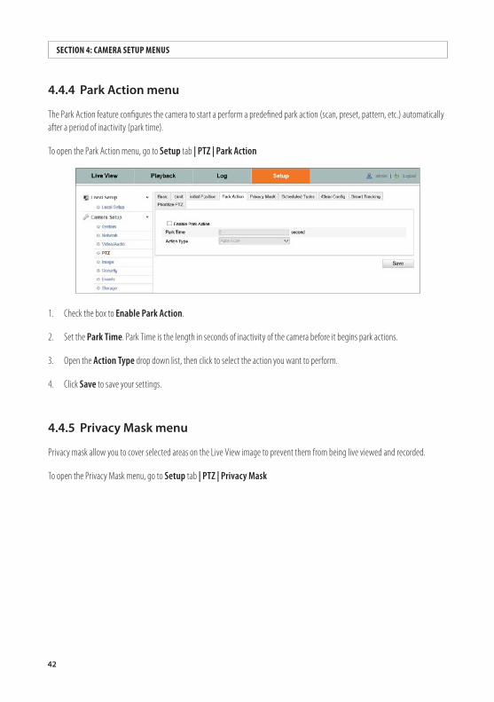
4.4.4 ParkActionmenu
The Park Action feature configures the camera to start a perform a predefined park action (scan, preset, pattern, etc.) automatically after a period of inactivity (park time).
To open the Park Action menu, go to Setup tab | PTZ | Park Action
1. Check the box to Enable Park Action.
2. Set the Park Time. Park Time is the length in seconds of inactivity of the camera before it begins park actions.
3. Open the Action Type drop down list, then click to select the action you want to perform.
4. Click Save to save your settings.
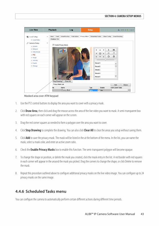
4.4.5 PrivacyMaskmenu
Privacy mask allow you to cover selected areas on the Live View image to prevent them from being live viewed and recorded.
To open the Privacy Mask menu, go to Setup tab | PTZ | Privacy Mask
SECTION 4: CAMERA SETUP MENUS
43ALIBI™ IP Camera Software User Manual
SECTION 4: CAMERA SETUP MENUS
Masked area over ATM keypad
1. Use the PTZ control buttons to display the area you want to cover with a privacy mask.
2. Click Draw Area, then click and drag the mouse across the area of the live video you want to mask. A semi-transparent box with red squares on each corner will appear on the screen.
3. Drag the red corner squares as needed to form a polygon over the area you want to cover.
4. Click Stop Drawing to complete the drawing. You can also click Clear All to clear the areas you setup without saving them.
5. Click Add to save the privacy mask. The mask will be listed in the at the bottom of the menu. In the list, you can name the mask, select a mask color, and enter an active zoom ratio.
6. Check the Enable Privacy Masks box to enable this function. The semi-transparent polygon will become opaque.
7. To change the shape or position, or delete the mask you created, click the mask entry in the list. A red border with red squares in each corner will appear in the around the mask you picked. Drag the corners to change the shape, or click Delete to remove the mask.
8. Repeat this procedure outlined above to configure additional privacy masks on the live video image. You can configure up to 24 privacy masks on the same image.
4.4.6 ScheduledTasksmenu
You can configure the camera to automatically perform certain different actions during different time periods.
44
SECTION 4: CAMERA SETUP MENUS
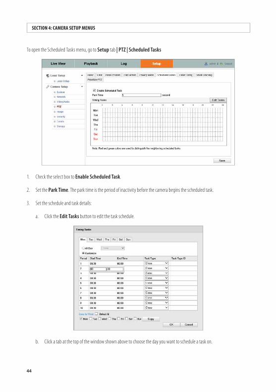
To open the Scheduled Tasks menu, go to Setup tab | PTZ | Scheduled Tasks
1. Check the select box to Enable Scheduled Task.
2. Set the Park Time. The park time is the period of inactivity before the camera begins the scheduled task.
3. Set the schedule and task details:
a. Click the Edit Tasks button to edit the task schedule.
b. Click a tab at the top of the window shown above to choose the day you want to schedule a task on.
45ALIBI™ IP Camera Software User Manual
SECTION 4: CAMERA SETUP MENUS
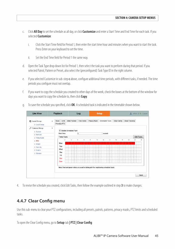
c. Click All Day to set the schedule as all day, or click Customize and enter a Start Time and End Time for each task. If you selected Customize:
i. Click the Start Time field for Period 1, then enter the start time hour and minutes when you want to start the task. Press Enter on your keyboard to set the time.
ii. Set the End Time field for Period 1 the same way.
d. Open the Task Type drop down list for Period 1, then select the task you want to perform during that period. If you selected Patrol, Pattern or Preset, also select the (preconfigured) Task Type ID in the right column.
e. If you selected Customize in sub-step c above, configure additional time periods, with different tasks, if needed. The time periods you configure must not overlap.
f. If you want to copy the schedule you created to other days of the week, check the boxes at the bottom of the window for days you want to copy the schedule to, then click Copy.
g. To save the schedule you specified, click OK. A scheduled task is indicated in the timetable shown below.
4. To revise the schedule you created, click Edit Tasks, then follow the example outlined in step 3 to make changes.
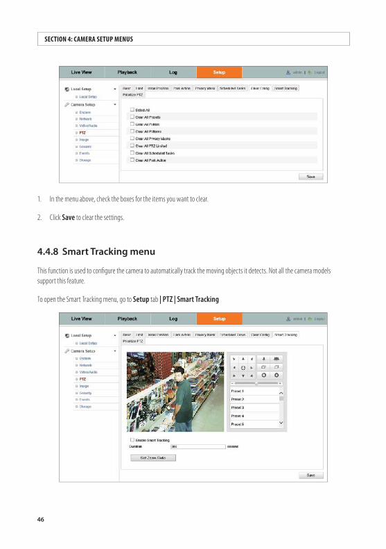
4.4.7 ClearConfigmenu
Use this sub-menu to clear your PTZ configurations, including all presets, patrols, patterns, privacy masks, PTZ limits and scheduled tasks.
To open the Clear Config menu, go to Setup tab | PTZ | Clear Config
46
1. In the menu above, check the boxes for the items you want to clear.
2. Click Save to clear the settings.
4.4.8 SmartTrackingmenu
This function is used to configure the camera to automatically track the moving objects it detects. Not all the camera models support this feature.
To open the Smart Tracking menu, go to Setup tab | PTZ | Smart Tracking
SECTION 4: CAMERA SETUP MENUS
47ALIBI™ IP Camera Software User Manual
SECTION 4: CAMERA SETUP MENUS
1. Check the Enable Smart Tracking box to enable this feature.
2. Click the PTZ buttons to select an object.
3. Click Set Zoom Ratio to set the current zoom ratio as the tracking zoom ratio.
4. Set the tracking duration. The camera will stop tracking when the duration ends. The duration can range from 0 to 300 seconds.
NOTE Setting the duration to 0 means that there’s no duration when the camera tracks (i.e., endless).
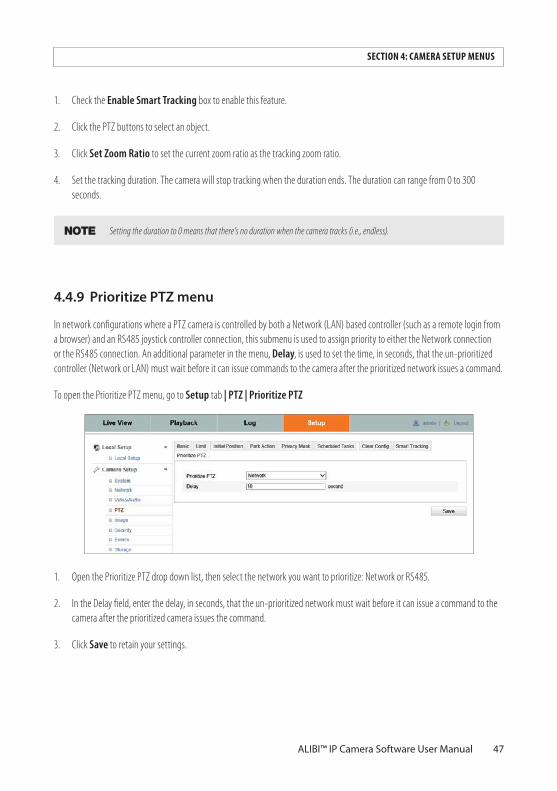
4.4.9 PrioritizePTZmenu
In network configurations where a PTZ camera is controlled by both a Network (LAN) based controller (such as a remote login from a browser) and an RS485 joystick controller connection, this submenu is used to assign priority to either the Network connection or the RS485 connection. An additional parameter in the menu, Delay, is used to set the time, in seconds, that the un-prioritized controller (Network or LAN) must wait before it can issue commands to the camera after the prioritized network issues a command.
To open the Prioritize PTZ menu, go to Setup tab | PTZ | Prioritize PTZ
1. Open the Prioritize PTZ drop down list, then select the network you want to prioritize: Network or RS485.
2. In the Delay field, enter the delay, in seconds, that the un-prioritized network must wait before it can issue a command to the camera after the prioritized camera issues the command.
3. Click Save to retain your settings.
48
4.5 Image menus
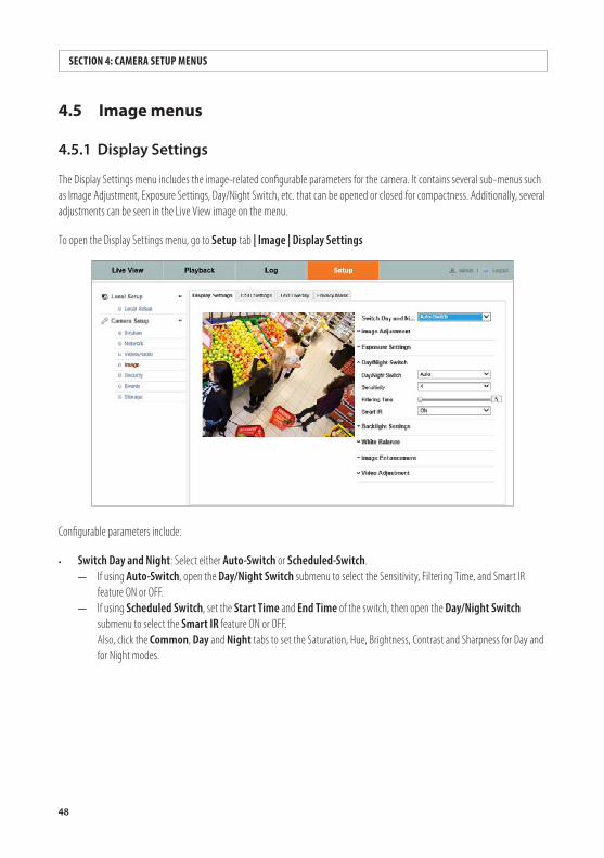
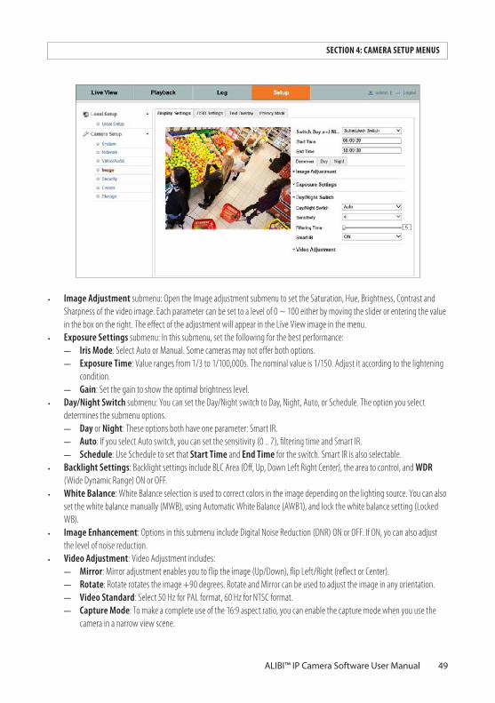
4.5.1 DisplaySettings
The Display Settings menu includes the image-related configurable parameters for the camera. It contains several sub-menus such as Image Adjustment, Exposure Settings, Day/Night Switch, etc. that can be opened or closed for compactness. Additionally, several adjustments can be seen in the Live View image on the menu.
To open the Display Settings menu, go to Setup tab | Image | Display Settings
Configurable parameters include:
• Switch Day and Night: Select either Auto-Switch or Scheduled-Switch. — If using Auto-Switch, open the Day/Night Switch submenu to select the Sensitivity, Filtering Time, and Smart IR
feature ON or OFF. — If using Scheduled Switch, set the Start Time and End Time of the switch, then open the Day/Night Switch
submenu to select the Smart IR feature ON or OFF.Also, click the Common, Day and Night tabs to set the Saturation, Hue, Brightness, Contrast and Sharpness for Day and for Night modes.
SECTION 4: CAMERA SETUP MENUS
49ALIBI™ IP Camera Software User Manual
SECTION 4: CAMERA SETUP MENUS
• Image Adjustment submenu: Open the Image adjustment submenu to set the Saturation, Hue, Brightness, Contrast and Sharpness of the video image. Each parameter can be set to a level of 0 ~ 100 either by moving the slider or entering the value in the box on the right. The effect of the adjustment will appear in the Live View image in the menu.
• Exposure Settings submenu: In this submenu, set the following for the best performance: — Iris Mode: Select Auto or Manual. Some cameras may not offer both options. — Exposure Time: Value ranges from 1/3 to 1/100,000s. The nominal value is 1/150. Adjust it according to the lightening
condition.— Gain: Set the gain to show the optimal brightness level.
• Day/Night Switch submenu: You can set the Day/Night switch to Day, Night, Auto, or Schedule. The option you select determines the submenu options.
— Day or Night: These options both have one parameter: Smart IR. — Auto: If you select Auto switch, you can set the sensitivity (0 .. 7), filtering time and Smart IR. — Schedule: Use Schedule to set that Start Time and End Time for the switch. Smart IR is also selectable.
• Backlight Settings: Backlight settings include BLC Area (Off, Up, Down Left Right Center), the area to control, and WDR (Wide Dynamic Range) ON or OFF.
• White Balance: White Balance selection is used to correct colors in the image depending on the lighting source. You can also set the white balance manually (MWB), using Automatic White Balance (AWB1), and lock the white balance setting (Locked WB).
• Image Enhancement: Options in this submenu include Digital Noise Reduction (DNR) ON or OFF. If ON, yo can also adjust the level of noise reduction.
• Video Adjustment: Video Adjustment includes: — Mirror: Mirror adjustment enables you to flip the image (Up/Down), flip Left/Right (reflect or Center). — Rotate: Rotate rotates the image +90 degrees. Rotate and Mirror can be used to adjust the image in any orientation. — Video Standard: Select 50 Hz for PAL format, 60 Hz for NTSC format. — Capture Mode: To make a complete use of the 16:9 aspect ratio, you can enable the capture mode when you use the
camera in a narrow view scene.
50
When installing the camera, turn the camera to the 90 degrees or rotate the 3-axis lens to 90 degrees, then set the capture mode to the screen size option you prefer.
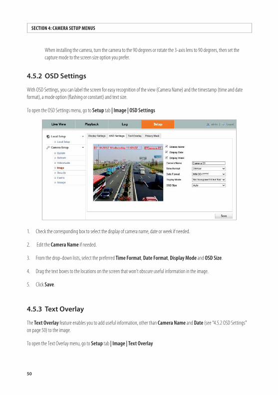
4.5.2 OSDSettings
With OSD Settings, you can label the screen for easy recognition of the view (Camera Name) and the timestamp (time and date format), a mode option (flashing or constant) and text size.
To open the OSD Settings menu, go to Setup tab | Image | OSD Settings
1. Check the corresponding box to select the display of camera name, date or week if needed.
2. Edit the Camera Name if needed.
3. From the drop-down lists, select the preferred Time Format, Date Format, Display Mode and OSD Size.
4. Drag the text boxes to the locations on the screen that won’t obscure useful information in the image.
5. Click Save.
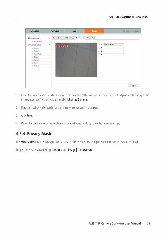
4.5.3 TextOverlay
The Text Overlay feature enables you to add useful information, other than Camera Name and Date (see “4.5.2 OSD Settings” on page 50) to the image.
To open the Text Overlay menu, go to Setup tab | Image | Text Overlay
SECTION 4: CAMERA SETUP MENUS
51ALIBI™ IP Camera Software User Manual
SECTION 4: CAMERA SETUP MENUS
1. Check the box in front of the label number on the right side of the window, then enter the text field you want to display. In the image above, box 1 is checked, and the label is Ceiling Camera.
2. Drag the text box to the location on the image where you want it displayed.
3. Click Save.
4. Repeat the steps above for the text labels, as needed. You can add up to four labels to one image.
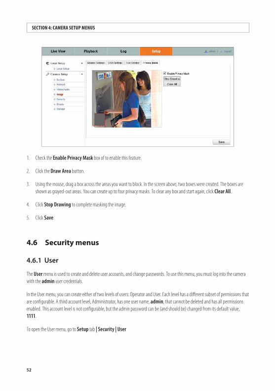
4.5.4 PrivacyMask
The Privacy Mask feature allows you to block areas of the live video image to prevent it from being viewed or recorded.
To open the Privacy Mask menu, go to Setup tab | Image | Text Overlay
52
SECTION 4: CAMERA SETUP MENUS
1. Check the Enable Privacy Mask box of to enable this feature.
2. Click the Draw Area button.
3. Using the mouse, drag a box across the areas you want to block. In the screen above, two boxes were created. The boxes are shown as grayed-out areas. You can create up to four privacy masks. To clear any box and start again, click Clear All.
4. Click Stop Drawing to complete masking the image.
5. Click Save.
4.6 Security menus
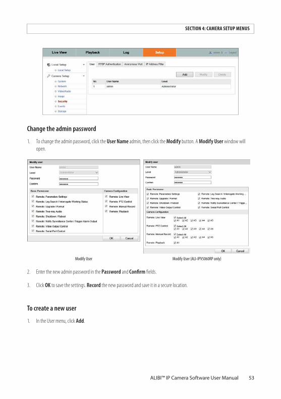
4.6.1 User
The User menu is used to create and delete user accounts, and change passwords. To use this menu, you must log into the camera with the admin user credentials.
In the User menu, you can create either of two levels of users: Operator and User. Each level has a different subset of permissions that are configurable. A third account level, Administrator, has one user name, admin, that cannot be deleted and has all permissions enabled. This account level is not configurable, but the admin password can be (and should be) changed from its default value, 1111.
To open the User menu, go to Setup tab | Security | User
53ALIBI™ IP Camera Software User Manual
SECTION 4: CAMERA SETUP MENUS
Change the admin password
1. To change the admin password, click the User Name admin, then click the Modify button. A Modify User window will open.
Modify User Modify User (ALI-IPV5060RP only)
2. Enter the new admin password in the Password and Confirm fields.
3. Click OK to save the settings. Record the new password and save it in a secure location.
To create a new user
1. In the User menu, click Add.
54
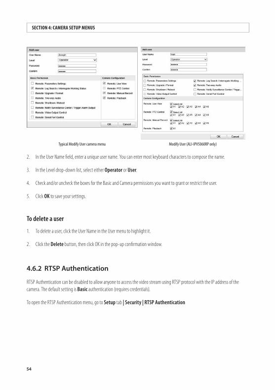
SECTION 4: CAMERA SETUP MENUS
Typical Modify User camera menu Modify User (ALI-IPV5060RP only)
2. In the User Name field, enter a unique user name. You can enter most keyboard characters to compose the name.
3. In the Level drop-down list, select either Operator or User.
4. Check and/or uncheck the boxes for the Basic and Camera permissions you want to grant or restrict the user.
5. Click OK to save your settings.
To delete a user
1. To delete a user, click the User Name in the User menu to highlight it.
2. Click the Delete button, then click OK in the pop-up confirmation window.
4.6.2 RTSPAuthentication
RTSP Authentication can be disabled to allow anyone to access the video stream using RTSP protocol with the IP address of the camera. The default setting is Basic authentication (requires credentials).
To open the RTSP Authentication menu, go to Setup tab | Security | RTSP Authentication
55ALIBI™ IP Camera Software User Manual
SECTION 4: CAMERA SETUP MENUS
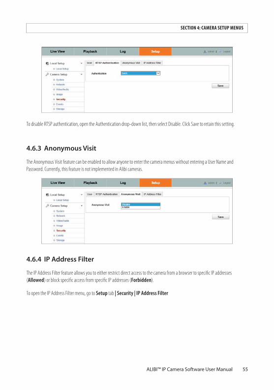
To disable RTSP authentication, open the Authentication drop-down list, then select Disable. Click Save to retain this setting.
4.6.3 AnonymousVisit
The Anonymous Visit feature can be enabled to allow anyone to enter the camera menus without entering a User Name and Password. Currently, this feature is not implemented in Alibi cameras.
4.6.4 IPAddressFilter
The IP Address Filter feature allows you to either restrict direct access to the camera from a browser to specific IP addresses (Allowed) or block specific access from specific IP addresses (Forbidden).
To open the IP Address Filter menu, go to Setup tab | Security | IP Address Filter
56
SECTION 4: CAMERA SETUP MENUS
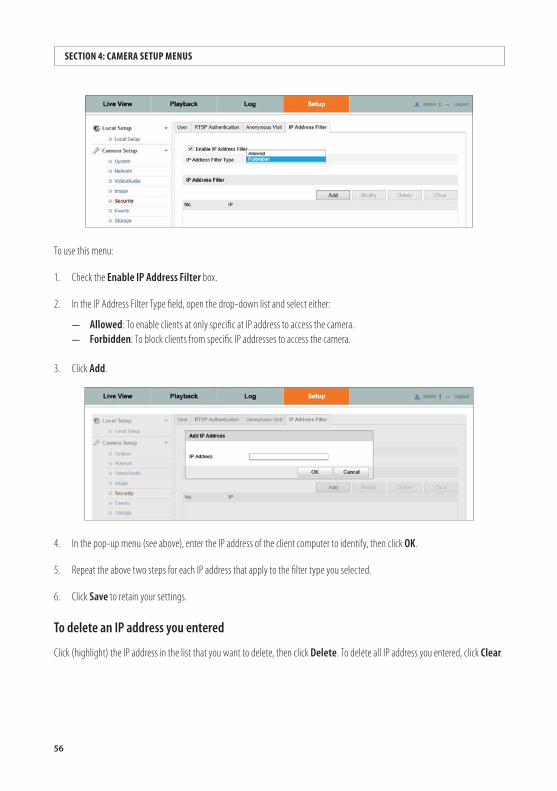
To use this menu:
1. Check the Enable IP Address Filter box.
2. In the IP Address Filter Type field, open the drop-down list and select either:
— Allowed: To enable clients at only specific at IP address to access the camera. — Forbidden: To block clients from specific IP addresses to access the camera.
3. Click Add.
4. In the pop-up menu (see above), enter the IP address of the client computer to identify, then click OK.
5. Repeat the above two steps for each IP address that apply to the filter type you selected.
6. Click Save to retain your settings.
To delete an IP address you entered
Click (highlight) the IP address in the list that you want to delete, then click Delete. To delete all IP address you entered, click Clear.
57ALIBI™ IP Camera Software User Manual
SECTION 4: CAMERA SETUP MENUS
To modify an IP address you entered
1. Click (highlight) the IP address in the list that you want to modify, then click Modify.
2. In the pop-up window, edit the IP address as needed.
3. Click OK to save the new address.
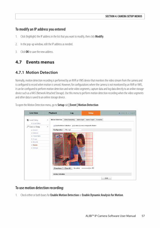
4.7 Events menus
4.7.1MotionDetection
Normally, motion detection recording is performed by an NVR or VMS device that monitors the video stream from the camera and is configured to record when motion is sensed. However, for configurations where the camera is not monitored by an NVR or VMS, it can be configured to perform motion detection and write video segments, capture data and log data directly to an online storage device such as a NAS (Network Attached Storage). Use this menu to perform motion detection recording when the video segments and other data is saved to an online storage device.
To open the Motion Detection menu, go to Setup tab | Event | Motion Detection
To use motion detection recording:
1. Check either or both boxes for Enable Motion Detection or Enable Dynamic Analysis for Motion.
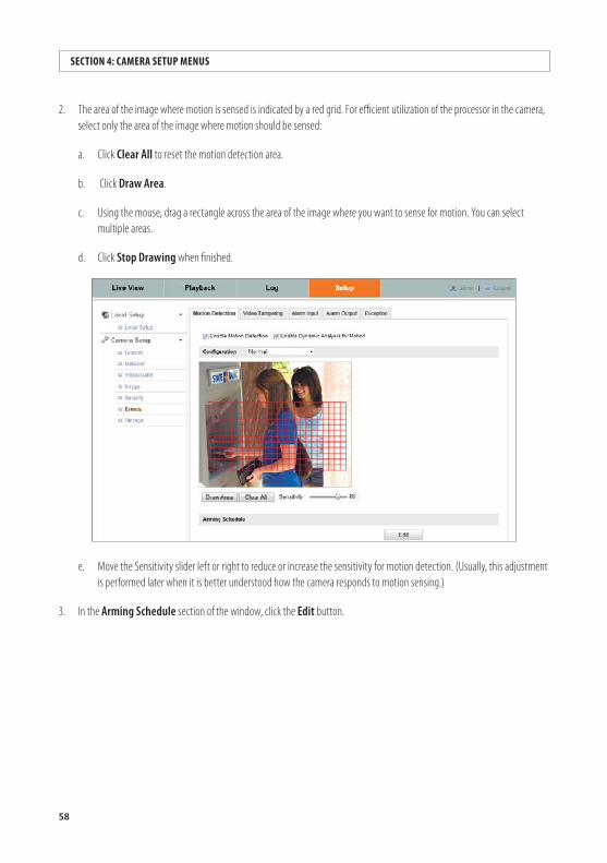
58
SECTION 4: CAMERA SETUP MENUS
2. The area of the image where motion is sensed is indicated by a red grid. For efficient utilization of the processor in the camera, select only the area of the image where motion should be sensed:
a. Click Clear All to reset the motion detection area.
b. Click Draw Area.
c. Using the mouse, drag a rectangle across the area of the image where you want to sense for motion. You can select multiple areas.
d. Click Stop Drawing when finished.
e. Move the Sensitivity slider left or right to reduce or increase the sensitivity for motion detection. (Usually, this adjustment is performed later when it is better understood how the camera responds to motion sensing.)
3. In the Arming Schedule section of the window, click the Edit button.
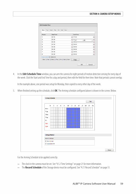
59ALIBI™ IP Camera Software User Manual
SECTION 4: CAMERA SETUP MENUS
4. In the Edit Schedule Time window, you can arm the camera for eight periods of motion detection sensing for every day of the week. Click the Start and End Time for a day and period, then edit the field for then time. Note that periods cannot overlap.
In the example above, one period was setup for Monday, then copied to every other day of the week.
5. When finished setting up the schedule, click OK. The Arming schedule configured above is shown in the screen. Below.
For the Arming Schedule to be applied correctly:
— The clock in the camera must be set. See “4.1.2 Time Settings” on page 21 for more information. — The Record Schedule of the Storage device must be configured. See “4.7.1 Record Schedule” on page 51.
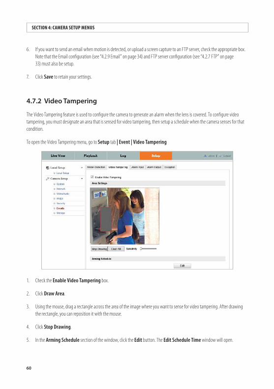
60
SECTION 4: CAMERA SETUP MENUS
6. If you want to send an email when motion is detected, or upload a screen capture to an FTP server, check the appropriate box. Note that the Email configuration (see “4.2.9 Email” on page 34) and FTP server configuration (see “4.2.7 FTP” on page 33) must also be setup.
7. Click Save to retain your settings.
4.7.2 VideoTampering
The Video Tampering feature is used to configure the camera to generate an alarm when the lens is covered. To configure video tampering, you must designate an area that is sensed for video tampering, then setup a schedule when the camera senses for that condition.
To open the Video Tampering menu, go to Setup tab | Event | Video Tampering
1. Check the Enable Video Tampering box.
2. Click Draw Area.
3. Using the mouse, drag a rectangle across the area of the image where you want to sense for video tampering. After drawing the rectangle, you can reposition it with the mouse.
4. Click Stop Drawing.
5. In the Arming Schedule section of the window, click the Edit button. The Edit Schedule Time window will open.
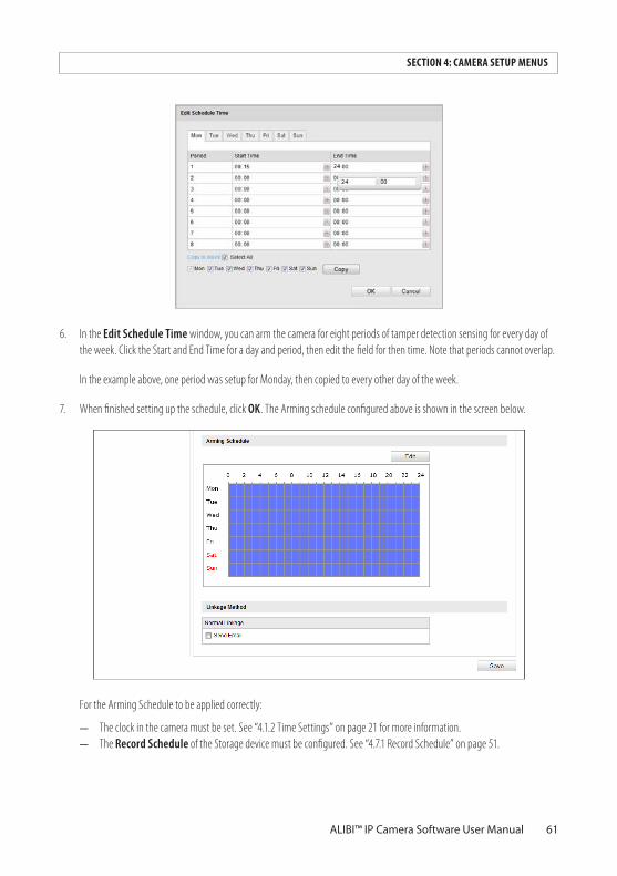
61ALIBI™ IP Camera Software User Manual
SECTION 4: CAMERA SETUP MENUS
6. In the Edit Schedule Time window, you can arm the camera for eight periods of tamper detection sensing for every day of the week. Click the Start and End Time for a day and period, then edit the field for then time. Note that periods cannot overlap.
In the example above, one period was setup for Monday, then copied to every other day of the week.
7. When finished setting up the schedule, click OK. The Arming schedule configured above is shown in the screen below.
For the Arming Schedule to be applied correctly:
— The clock in the camera must be set. See “4.1.2 Time Settings” on page 21 for more information. — The Record Schedule of the Storage device must be configured. See “4.7.1 Record Schedule” on page 51.
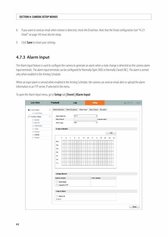
62
SECTION 4: CAMERA SETUP MENUS
8. If you want to send an email when motion is detected, check the Email box. Note that the Email configuration (see “4.2.9 Email” on page 34) must also be setup.
9. Click Save to retain your settings.
4.7.3 AlarmInput
The Alarm Input feature is used to configure the camera to generate an alarm when a state change is detected on the camera alarm input terminals. The alarm input terminals can be configured for Normally Open (NO) or Normally Closed (NC). The alarm is armed only when enabled in the Arming Schedule.
When an input alarm is sensed when enabled in the Arming Schedule, the camera can send an email alert or upload the alarm information to an FTP server, if selected in the menu.
To open the Alarm Input menu, go to Setup tab | Event | Alarm Input
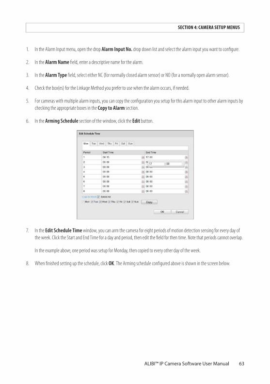
63ALIBI™ IP Camera Software User Manual
SECTION 4: CAMERA SETUP MENUS
1. In the Alarm Input menu, open the drop Alarm Input No. drop down list and select the alarm input you want to configure.
2. In the Alarm Name field, enter a descriptive name for the alarm.
3. In the Alarm Type field, select either NC (for normally closed alarm sensor) or NO (for a normally open alarm sensor).
4. Check the box(es) for the Linkage Method you prefer to use when the alarm occurs, if needed.
5. For cameras with multiple alarm inputs, you can copy the configuration you setup for this alarm input to other alarm inputs by checking the appropriate boxes in the Copy to Alarm section.
6. In the Arming Schedule section of the window, click the Edit button.
7. In the Edit Schedule Time window, you can arm the camera for eight periods of motion detection sensing for every day of the week. Click the Start and End Time for a day and period, then edit the field for then time. Note that periods cannot overlap.
In the example above, one period was setup for Monday, then copied to every other day of the week.
8. When finished setting up the schedule, click OK. The Arming schedule configured above is shown in the screen below.
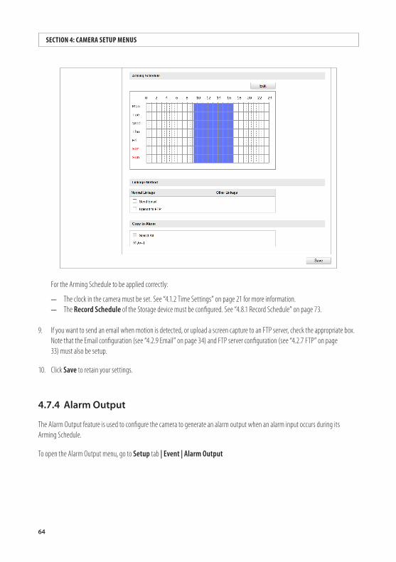
64
SECTION 4: CAMERA SETUP MENUS
For the Arming Schedule to be applied correctly:
— The clock in the camera must be set. See “4.1.2 Time Settings” on page 21 for more information. — The Record Schedule of the Storage device must be configured. See “4.8.1 Record Schedule” on page 73.
9. If you want to send an email when motion is detected, or upload a screen capture to an FTP server, check the appropriate box. Note that the Email configuration (see “4.2.9 Email” on page 34) and FTP server configuration (see “4.2.7 FTP” on page 33) must also be setup.
10. Click Save to retain your settings.
4.7.4 AlarmOutput
The Alarm Output feature is used to configure the camera to generate an alarm output when an alarm input occurs during its Arming Schedule.
To open the Alarm Output menu, go to Setup tab | Event | Alarm Output
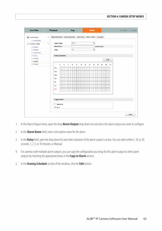
65ALIBI™ IP Camera Software User Manual
SECTION 4: CAMERA SETUP MENUS
1. In the Alarm Output menu, open the drop Alarm Output drop down list and select the alarm output you want to configure.
2. In the Alarm Name field, enter a descriptive name for the alarm.
3. In the Delay field, open the drop down list and select duration of the alarm output is active. You can select either 5, 10, or 30 seconds, 1, 2, 5, or 10 minutes, or Manual.
4. For cameras with multiple alarm outputs, you can copy the configuration you setup for this alarm output to other alarm outputs by checking the appropriate boxes in the Copy to Alarm section.
5. In the Arming Schedule section of the window, click the Edit button.
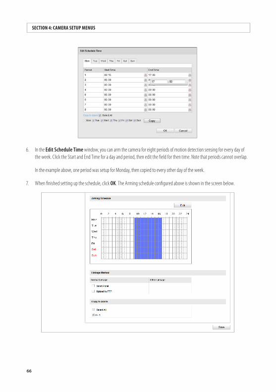
66
SECTION 4: CAMERA SETUP MENUS
6. In the Edit Schedule Time window, you can arm the camera for eight periods of motion detection sensing for every day of the week. Click the Start and End Time for a day and period, then edit the field for then time. Note that periods cannot overlap.
In the example above, one period was setup for Monday, then copied to every other day of the week.
7. When finished setting up the schedule, click OK. The Arming schedule configured above is shown in the screen below.
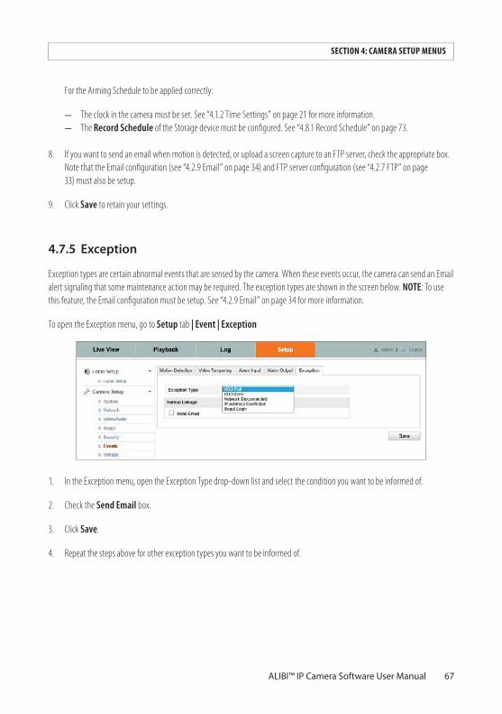
67ALIBI™ IP Camera Software User Manual
SECTION 4: CAMERA SETUP MENUS
For the Arming Schedule to be applied correctly:
— The clock in the camera must be set. See “4.1.2 Time Settings” on page 21 for more information. — The Record Schedule of the Storage device must be configured. See “4.8.1 Record Schedule” on page 73.
8. If you want to send an email when motion is detected, or upload a screen capture to an FTP server, check the appropriate box. Note that the Email configuration (see “4.2.9 Email” on page 34) and FTP server configuration (see “4.2.7 FTP” on page 33) must also be setup.
9. Click Save to retain your settings.
4.7.5 Exception
Exception types are certain abnormal events that are sensed by the camera. When these events occur, the camera can send an Email alert signaling that some maintenance action may be required. The exception types are shown in the screen below. NOTE: To use this feature, the Email configuration must be setup. See “4.2.9 Email” on page 34 for more information.
To open the Exception menu, go to Setup tab | Event | Exception
1. In the Exception menu, open the Exception Type drop-down list and select the condition you want to be informed of.
2. Check the Send Email box.
3. Click Save.
4. Repeat the steps above for other exception types you want to be informed of.
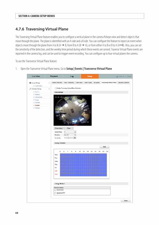
68
SECTION 4: CAMERA SETUP MENUS
4.7.6 TraversingVirtualPlane
The Traversing Virtual Plane feature enables you to configure a vertical plane in the camera fisheye view and detect objects that move through the plane. The plane is identified with an A side and a B side. You can configure the feature to report an event when objects move through the plane from A to B (A B, from B to A (B A), or from either A to B or B to A (A B). Also, you can set the sensitivity of the detection, and the weekly time period during which these events are sensed. Traverse Virtual Plane events are reported in the camera log, and can be used to trigger event recording. You can configure up to four virtual planes the camera.
To use the Transverse Virtual Plane feature:
1. Open the Transverse Virtual Plane menu. Go to Setup | Events | Transverse Virtual Plane
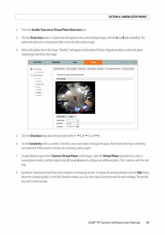
69ALIBI™ IP Camera Software User Manual
SECTION 4: CAMERA SETUP MENUS
2. Check the Enable Transverse Virtual Plane Detection box.
3. Click the Draw Area button. A yellow line will appear on the camera fisheye image, with the A and B sides identified. The yellow line represents a virtual plane that is vertical to the camera image.
4. Click on the yellow line in the image. “Handles” will appear at both ends of the line. Drag the handles to where the plane should begin and end in the image.
5. Click the Direction drop down list and select either A B, B A, or A B.
6. Set the Sensitivity slider as needed. To do that, move some objects through the plane, then monitor the log to verify they were detected. If they weren’t, increase the sensitivity, and try again.
7. To add additional (up to four) Traverse Virtual Planes to the image , open the Virtual Plane drop down list, select a unused plane number, and then repeat steps 3 through 6 above to configure an additional plane. If not, continue with the next step.
8. By default, Traversing Virtual Plane when enabled is continuously armed. To change the arming schedule, click the Edit button above the schedule graphic. In the Edit Schedule window, you can select up to 8 armed periods for each weekday. The periods you select cannot overlap.
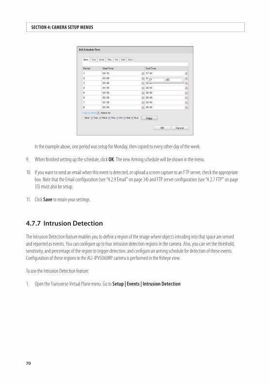
70
SECTION 4: CAMERA SETUP MENUS
In the example above, one period was setup for Monday, then copied to every other day of the week.
9. When finished setting up the schedule, click OK. The new Arming schedule will be shown in the menu.
10. If you want to send an email when this event is detected, or upload a screen capture to an FTP server, check the appropriate box. Note that the Email configuration (see “4.2.9 Email” on page 34) and FTP server configuration (see “4.2.7 FTP” on page 33) must also be setup.
11. Click Save to retain your settings.
4.7.7 IntrusionDetection
The Intrusion Detection feature enables you to define a region of the image where objects intruding into that space are sensed and reported as events. You can configure up to four intrusion detection regions in the camera. Also, you can set the threshold, sensitivity, and percentage of the region to trigger detection, and configure an arming schedule for detection of these events. Configuration of these regions in the ALI-IPV5060RP camera is performed in the fisheye view.
To use the Intrusion Detection feature:
1. Open the Transverse Virtual Plane menu. Go to Setup | Events | Intrusion Detection
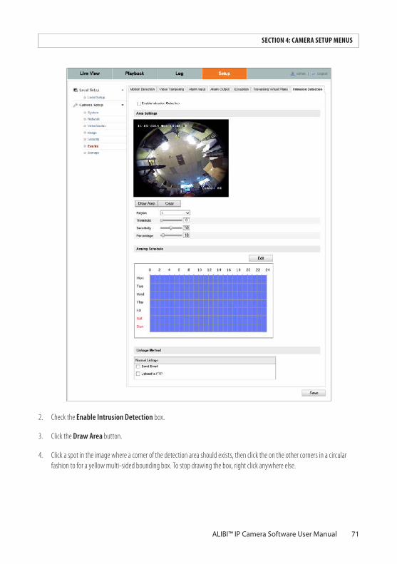
71ALIBI™ IP Camera Software User Manual
SECTION 4: CAMERA SETUP MENUS
2. Check the Enable Intrusion Detection box.
3. Click the Draw Area button.
4. Click a spot in the image where a corner of the detection area should exists, then click the on the other corners in a circular fashion to for a yellow multi-sided bounding box. To stop drawing the box, right click anywhere else.
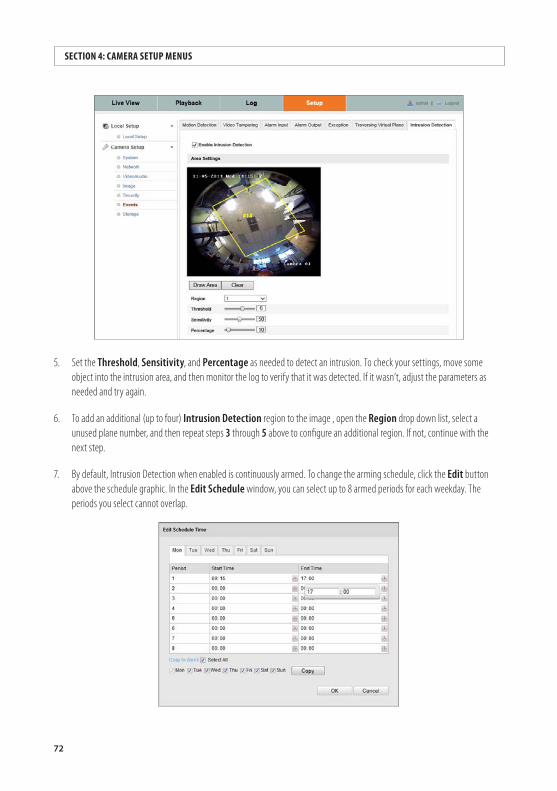
72
SECTION 4: CAMERA SETUP MENUS
5. Set the Threshold, Sensitivity, and Percentage as needed to detect an intrusion. To check your settings, move some object into the intrusion area, and then monitor the log to verify that it was detected. If it wasn’t, adjust the parameters as needed and try again.
6. To add an additional (up to four) Intrusion Detection region to the image , open the Region drop down list, select a unused plane number, and then repeat steps 3 through 5 above to configure an additional region. If not, continue with the next step.
7. By default, Intrusion Detection when enabled is continuously armed. To change the arming schedule, click the Edit button above the schedule graphic. In the Edit Schedule window, you can select up to 8 armed periods for each weekday. The periods you select cannot overlap.
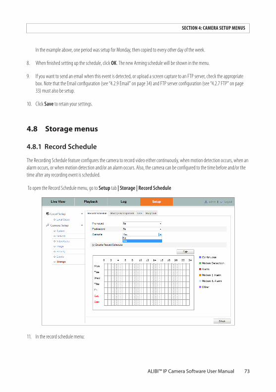
73ALIBI™ IP Camera Software User Manual
SECTION 4: CAMERA SETUP MENUS
In the example above, one period was setup for Monday, then copied to every other day of the week.
8. When finished setting up the schedule, click OK. The new Arming schedule will be shown in the menu.
9. If you want to send an email when this event is detected, or upload a screen capture to an FTP server, check the appropriate box. Note that the Email configuration (see “4.2.9 Email” on page 34) and FTP server configuration (see “4.2.7 FTP” on page 33) must also be setup.
10. Click Save to retain your settings.
4.8 Storage menus
4.8.1 RecordSchedule
The Recording Schedule feature configures the camera to record video either continuously, when motion detection occurs, when an alarm occurs, or when motion detection and/or an alarm occurs. Also, the camera can be configured to the time before and/or the time after any recording event is scheduled.
To open the Record Schedule menu, go to Setup tab | Storage | Record Schedule
11. In the record schedule menu:
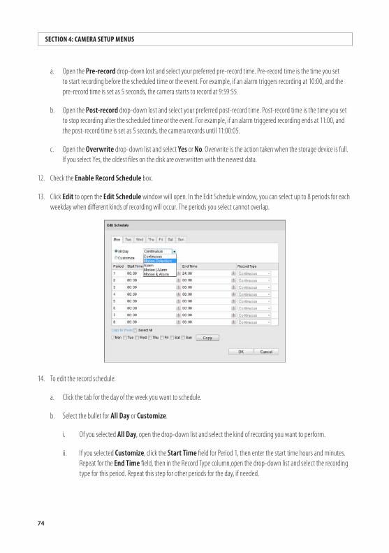
74
SECTION 4: CAMERA SETUP MENUS
a. Open the Pre-record drop-down lost and select your preferred pre-record time. Pre-record time is the time you set to start recording before the scheduled time or the event. For example, if an alarm triggers recording at 10:00, and the pre-record time is set as 5 seconds, the camera starts to record at 9:59:55.
b. Open the Post-record drop-down lost and select your preferred post-record time. Post-record time is the time you set to stop recording after the scheduled time or the event. For example, if an alarm triggered recording ends at 11:00, and the post-record time is set as 5 seconds, the camera records until 11:00:05.
c. Open the Overwrite drop-down list and select Yes or No. Overwrite is the action taken when the storage device is full. If you select Yes, the oldest files on the disk are overwritten with the newest data.
12. Check the Enable Record Schedule box.
13. Click Edit to open the Edit Schedule window will open. In the Edit Schedule window, you can select up to 8 periods for each weekday when different kinds of recording will occur. The periods you select cannot overlap.
14. To edit the record schedule:
a. Click the tab for the day of the week you want to schedule.
b. Select the bullet for All Day or Customize.
i. Of you selected All Day, open the drop-down list and select the kind of recording you want to perform.
ii. If you selected Customize, click the Start Time field for Period 1, then enter the start time hours and minutes. Repeat for the End Time field, then in the Record Type column,open the drop-down list and select the recording type for this period. Repeat this step for other periods for the day, if needed.
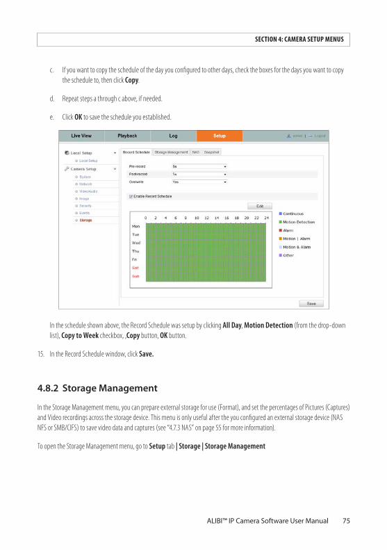
75ALIBI™ IP Camera Software User Manual
SECTION 4: CAMERA SETUP MENUS
c. If you want to copy the schedule of the day you configured to other days, check the boxes for the days you want to copy the schedule to, then click Copy.
d. Repeat steps a through c above, if needed.
e. Click OK to save the schedule you established.
In the schedule shown above, the Record Schedule was setup by clicking All Day, Motion Detection (from the drop-down list), Copy to Week checkbox, ,Copy button, OK button.
15. In the Record Schedule window, click Save.
4.8.2 StorageManagement
In the Storage Management menu, you can prepare external storage for use (Format), and set the percentages of Pictures (Captures) and Video recordings across the storage device. This menu is only useful after the you configured an external storage device (NAS NFS or SMB/CIFS) to save video data and captures (see “4.7.3 NAS” on page 55 for more information).
To open the Storage Management menu, go to Setup tab | Storage | Storage Management
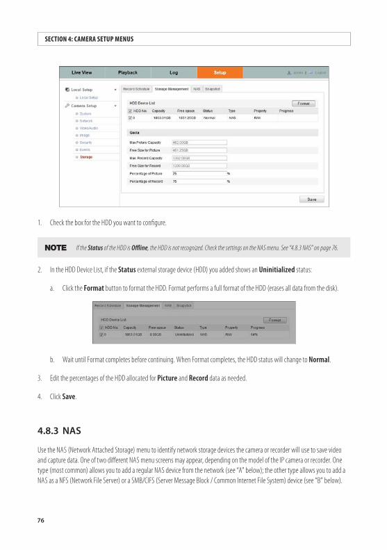
76
SECTION 4: CAMERA SETUP MENUS
1. Check the box for the HDD you want to configure.
NOTE If the Status of the HDD is Offline, the HDD is not recognized. Check the settings on the NAS menu. See “4.8.3 NAS” on page 76.
2. In the HDD Device List, if the Status external storage device (HDD) you added shows an Uninitialized status:
a. Click the Format button to format the HDD. Format performs a full format of the HDD (erases all data from the disk).
b. Wait until Format completes before continuing. When Format completes, the HDD status will change to Normal.
3. Edit the percentages of the HDD allocated for Picture and Record data as needed.
4. Click Save.
4.8.3 NAS
Use the NAS (Network Attached Storage) menu to identify network storage devices the camera or recorder will use to save video and capture data. One of two different NAS menu screens may appear, depending on the model of the IP camera or recorder. One type (most common) allows you to add a regular NAS device from the network (see “A” below); the other type allows you to add a NAS as a NFS (Network File Server) or a SMB/CIFS (Server Message Block / Common Internet File System) device (see “B” below).
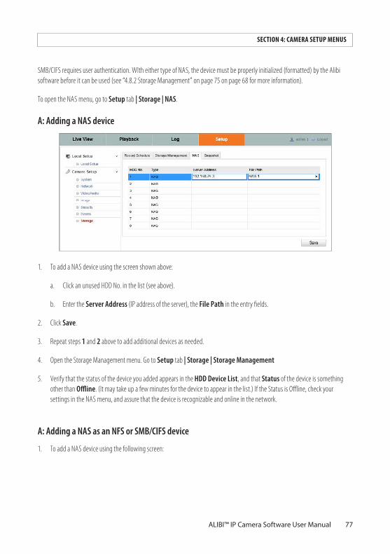
77ALIBI™ IP Camera Software User Manual
SECTION 4: CAMERA SETUP MENUS
SMB/CIFS requires user authentication. WIth either type of NAS, the device must be properly initialized (formatted) by the Alibi software before it can be used (see “4.8.2 Storage Management” on page 75 on page 68 for more information).
To open the NAS menu, go to Setup tab | Storage | NAS.
A: Adding a NAS device
1. To add a NAS device using the screen shown above:
a. Click an unused HDD No. in the list (see above).
b. Enter the Server Address (IP address of the server), the File Path in the entry fields.
2. Click Save.
3. Repeat steps 1 and 2 above to add additional devices as needed.
4. Open the Storage Management menu. Go to Setup tab | Storage | Storage Management
5. Verify that the status of the device you added appears in the HDD Device List, and that Status of the device is something other than Offline. (It may take up a few minutes for the device to appear in the list.) If the Status is Offline, check your settings in the NAS menu, and assure that the device is recognizable and online in the network.
A: Adding a NAS as an NFS or SMB/CIFS device
1. To add a NAS device using the following screen:
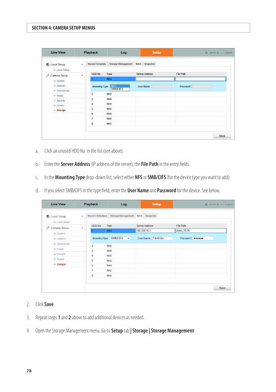
78
SECTION 4: CAMERA SETUP MENUS
a. Click an unused HDD No. in the list (see above).
b. Enter the Server Address (IP address of the server), the File Path in the entry fields.
c. In the Mounting Type drop-down list, select either NFS or SMB/CIFS (for the device type you want to add).
d. If you select SMB/CIFS in the type field, enter the User Name and Password for the device. See below.
2. Click Save.
3. Repeat steps 1 and 2 above to add additional devices as needed.
4. Open the Storage Management menu. Go to Setup tab | Storage | Storage Management
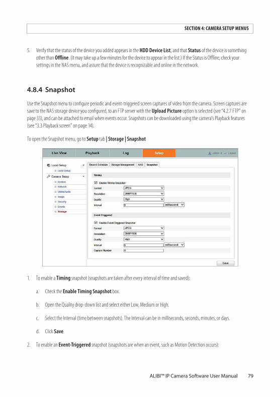
79ALIBI™ IP Camera Software User Manual
SECTION 4: CAMERA SETUP MENUS
5. Verify that the status of the device you added appears in the HDD Device List, and that Status of the device is something other than Offline. (It may take up a few minutes for the device to appear in the list.) If the Status is Offline, check your settings in the NAS menu, and assure that the device is recognizable and online in the network.
4.8.4 Snapshot
Use the Snapshot menu to configure periodic and event-triggered screen captures of video from the camera. Screen captures are save to the NAS storage device you configured, to an FTP server with the Upload Picture option is selected (see “4.2.7 FTP” on page 33), and can be attached to email when events occur. Snapshots can be downloaded using the camera’s Playback features (see “3.3 Playback screen” on page 14).
To open the Snapshot menu, go to Setup tab | Storage | Snapshot
1. To enable a Timing snapshot (snapshots are taken after every interval of time and saved):
a. Check the Enable Timing Snapshot box.
b. Open the Quality drop-down list and select either Low, Medium or High.
c. Select the Interval (time between snapshots). The Interval can be in milliseconds, seconds, minutes, or days.
d. Click Save.
2. To enable an Event-Triggered snapshot (snapshots are when an event, such as Motion Detection occurs):
80
SECTION 4: CAMERA SETUP MENUS
a. Check the Enable Event-Triggered Snapshot box.
b. Open the Quality drop-down list and select either Low, Medium or High.
c. Select the Interval (time between snapshots). The Interval range can be 1000 ms ~ 65535 ms.
d. Click Save.