alice electronics upgrade technical design report of the alice high rate detector upgrade
DESCRIPTION
ALICE electronics upgrade Technical design report of the ALICE high rate detector upgrade. A. Kluge, 24 September 2013. Upgrade Overview. data taking & trigger strategy architecture detector overview read-out capabilites upgrade developments common developments - PowerPoint PPT PresentationTRANSCRIPT

Sept 24, 2013 A. Kluge 1
ALICE electronics upgrade
Technical design report of the ALICE high rate detector upgrade
A. Kluge, 24 September 2013

Sept 24, 2013 A. Kluge 2
Upgrade Overview
• data taking & trigger strategy• architecture• detector overview– read-out capabilites
• upgrade developments– common developments– detector specific developments

Sept 24, 2013 A. Kluge 3
Upgrade overview- RO and trigger

Sept 24, 2013 A. Kluge 4
Upgrade overview- RO and trigger
• General principle:– store all information from interactions (if possible)– upgrade detectors to• trigger-less, data driven continuous read-out
Detector frontendfront-end links CRU
trig distrCTPtrigger link
DDLFLP

Sept 24, 2013 A. Kluge 5
Upgrade overview- RO and trigger
• Upgrade to a continuous/trigger-lessread-out of:– TPC– muon chamber (MCH)– inner tracking system (ITS)
• for an interaction rate of 50 kHz– with a design margin to 100 kHz for the read-out
Detector frontendfront-end links CRU
trig distrCTPtrigger link
DDLFLP

Sept 24, 2013 A. Kluge 6
Upgrade overview- RO and trigger
• All other detectors have a triggered read-out
Detector frontendfront-end links CRU
trig distrCTPtrigger link
DDLFLP

Sept 24, 2013 A. Kluge 7
Upgrade overview- RO and trigger
• Two groups of detectors:• continuous read-out and triggered detectors:– ALICE still needs a trigger signal:– interaction trigger
Detector frontendfront-end links CRU
trig distrCTPtrigger link
DDLFLP

Sept 24, 2013 A. Kluge 8
Upgrade overview- RO and trigger
• Within triggered detector group:– Those with and without multi-event buffer– With different maximum read-out rate• with different live (not busy) time

Sept 24, 2013 A. Kluge 9
Upgrade overview- RO and trigger
• Concept: Upon interaction trigger read-out all detectors which are not busy
• Trigger scaling for specific combination of detectors optional.– Control by Central Trigger Processor (CTP)– trigger cluster

Sept 24, 2013 A. Kluge 10
Upgrade overview- Summary trigger
• Interaction trigger for triggered detectors• Suppression of trigger transmission to detectors
already busy • Possible beam or sensor induced noise rejection
for ITS • Commissioning, cosmic runs
• Consequence continuous read-out detectors (TPC, MCH, ITS) need trigger capability

Sept 24, 2013 A. Kluge 11
Upgrade overview- Summary trigger
• Option: Statistic scaling for detector combination with low read-out rate (EMC, PHO, HMP)
• Option: Interaction rate down scaling if DAQ is not fully active
Sept 24, 2013 A. Kluge 12
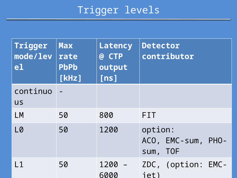
Trigger levels
Trigger mode/level
Max rate PbPb [kHz]
Latency @ CTP output [ns]
Detector contributor
continuous -
LM 50 800 FIT
L0 50 1200 option: ACO, EMC-sum, PHO-sum, TOF
L1 50 1200 – 6000
ZDC, (option: EMC-jet)

Sept 24, 2013 A. Kluge 13
Central Trigger Processor
FITtrig_outtrig_in
data_outbusy_out
ACOtrig_outtrig_in
data_out
EMCtrig_outtrig_in
data_out
PHOtrig_outtrig_in
data_out
TOFtrig_outtrig_in
data_out
ZDCtrig_outtrig_in
data_out
LM procLM_in LM_out LM_cable
L0 procL0_in
L0_in
L0_in
L0_in
L1 procL1_in
L1_out
trig distrTTC
trig distrGBT
trig_TTC
trig_GBT
busy_GBT
L0_out L0_cable
CTPbusy handler
busy_cable
busy_DAQ

Sept 24, 2013 A. Kluge 14
DAQ & heartbeat trigger

Sept 24, 2013 A. Kluge 15
DAQ & heartbeat trigger
• Continuous & triggered read-out collects (time) slices – time frames > 100 ms
• Continuous read-out detectors – data stream separated in time frames – using heart beat triggers sent at time frame
boundary

Sept 24, 2013 A. Kluge 16
DAQ & heartbeat trigger
• Heart beat trigger (hb)– creates time frame boundary– sends bunch crossing (bxc) and orbit counters (oc)• FE re-synchronises
– TTC system will not send full bxc & oc• bandwidth excess
– also triggered detectors get hb trigger
Sept 24, 2013 A. Kluge 17
Read-out architecture

Sept 24, 2013 A. Kluge 18
Read-out architecture
• General principle:– store all data from interactions (if possible)– includes a trigger processor
Detector frontendfront-end links CRU
trig distrCTP
trigger link & busy
DDLFLP

Sept 24, 2013 A. Kluge 19
Read-out architecture
• Standard interface to DAQ/DCS– Detector Data Links DDL 1, 2 already developed• 2.125 and 4.25/5.3125 Gb/s
– DDL3 still to be developed• ≤ 10 Gb/s GbE or PCIe over cable or PCIe plug-in cards
• Standard interface to Trigger– GBT links– TTC links for non-upgraded electronics
Detector frontendfront-end links CRU
trig distrCTPtrigger link
DDLFLP

Sept 24, 2013 A. Kluge 20
Architecture – common read-out unit CRU
• ALICE standard common read-out unit CRU used by new detectors & those who upgrade– TPC, MCH, ITS, TRD, ZDC, MID
Detector frontendfront-end links CRU
trig distrCTPtrigger link
DDLFLP
Sept 24, 2013 A. Kluge 21
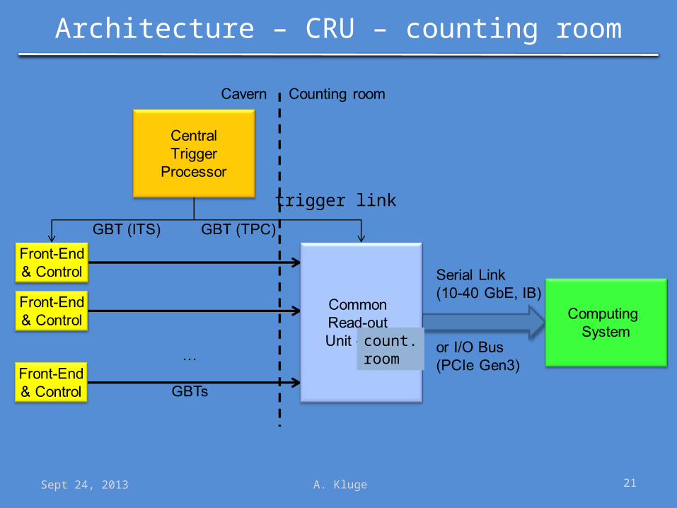
Architecture – CRU – counting room
count.room
trigger link

Sept 24, 2013 A. Kluge 22
Architecture – CRU – counting room
• TPC is cost defining factor for optical fibers:– CRU – counting room study
based on the LHCb read-out board AMC40• 6300 TPC front-end links with SEU correction• 4700 TPC front-end links without SEU correction– TPC front-end links only partly bi-directional
countroom
trigger link

Sept 24, 2013 A. Kluge 23
Architecture – CRU – cavern
cavern
trigger link

Sept 24, 2013 A. Kluge 24
Architecture – CRU – counting room
• TPC is cost defining factor for optical fibers:• 1836 DDL fibers, all bi-directional• up to 1836 trigger fibers
cavern
trigger link
Sept 24, 2013 A. Kluge 25
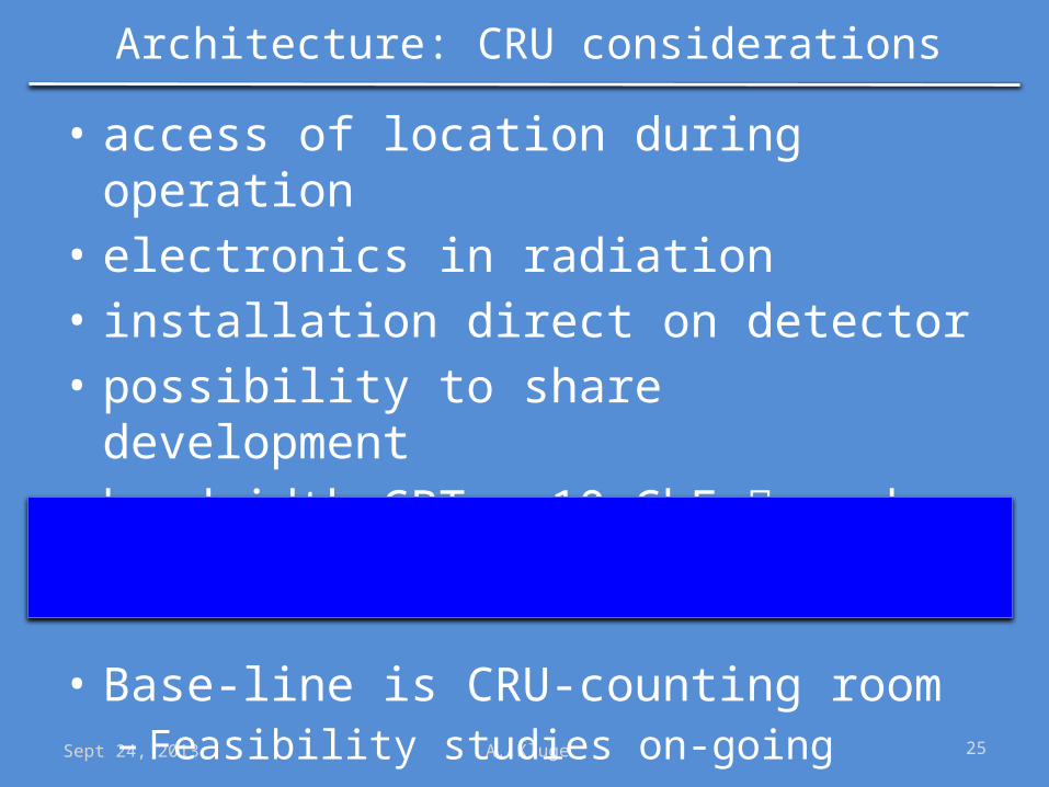
Architecture: CRU considerations
• access of location during operation• electronics in radiation• installation direct on detector• possibility to share development• bandwidth GBT – 10 GbE number of fibers
• Base-line is CRU-counting room– Feasibility studies on-going

Sept 24, 2013 A. Kluge 26
Detector Overview

Sept 24, 2013 A. Kluge 27
Detector Overview
• trigger needed max RO rate busy > 0%(kHz)
– TPC 50– MCH 100– ITS: 100– TOF: Y 100 – MUONID: Y >100 – FIT: Y 200 – ZDC: Y >100– PHOS: Y 46 Y– TRD: Y 50 Y– EMCAL: Y 46 Y– HMPID: Y 2 Y

Sept 24, 2013 A. Kluge 28
Detector Overview: new components
• FE ASIC FEC MUX
– TPC 17k SAMPA 3400 CRU– MCH 33k SAMPA 550 CRU– ITS: 25k pixel ASIC 200 CRU/other– TOF: 72 DRM– MUONID: FEERIC 234 CRU– FIT: upgrade DRM(TOF)– ZDC: commercial CRU– PHOS: – TRD: CRU– EMCAL: – HMPID:

Sept 24, 2013 A. Kluge 29
Detector developments: common
• common read-out ASIC – SAMPA• TPC & muon chambers (MCH)

Sept 24, 2013 A. Kluge 30
Detector developments: SAMPA
• common read-out ASIC – SAMPA• TPC & muon chambers (MCH)

Sept 24, 2013 A. Kluge 31
Detector developments: common
• common read-out ASIC – SAMPA• TPC & muon chambers (MCH)– 32 channel amplifier-shaper-ADC-DSP– trigger less or continuous read-out– <600 e @ 25 pF (TPC), < 750 e @ 40 p (MCH)– bi-polarity input– 10 bit ADC – 10 Msamples/s– on ASIC base-line correction and zero suppression– 4 x 320 Mbit/s serial outputs– 130 nm TSMC CMOS process

Sept 24, 2013 A. Kluge 32
Detector developments: TPC
• ~ 500.000 pads• MWPCs replaced by GEMs for 50 kHz read-out rate• upgrade to continuous read-out @ 50 kHz interaction rate• 4320 Front-end cards are replaced • ~ 17.000 SAMPA ASICs
– baseline specifications:• input charge: < 100 fC,• 160 ns shaping time, • 10 MHz ADC sampling, • 10 bit resolution
• RCUs are replaced by CRUs allowing continuous read-out• Trigger optional
FECFE-ASIC Data
MUXDDL 3
Sensor

Sept 24, 2013 A. Kluge 33
Detector developments: ITS
• 25 G pixels• complete new detector– ASIC, sensor, read-out, mechanics cooling
• continuous read-out @ 100 kHz hit rate • trigger option– to decrease effects to due possible beam/sensor effects
• Detector module sends data 1 Gb/s links– base-line electrical– close to detector link interface needed
• Baseline read-out concentrator CRU
FECFE-ASIC Data
MUXDDL 3
Sensor

Sept 24, 2013 A. Kluge 34
Detector developments: muon chamber
• ~1.000.000 MWPC• upgrade to continuous read-out @ 100 kHz hit rate• Replacement of the front-end by ~ 33.000 SAMPA ASIC
– baseline specifications:– input charge: < 400 fC,– 330 ns shaping time, – 10 MHz ADC sampling, – 10 bit resolution
• Replacement of active patch panels (first level of data concentration)– based on GBTs or electrical e-links
• Replacement of data concentrator by CRUs
FECFE-ASIC Data
MUXDDL 3
Sensor

Sept 24, 2013 A. Kluge 35
Detector developments: muon identifier
• 21.000 RPC• replacement of front-end electronics
to slow down aging speed of RPCs– by operation in avalanche mode reducing charge
produced in the gas• Front-end ASIC is replaced by FEERIC ASIC– with amplification
• Read-out out at 100 kHz @ 0 % busy• Suppression of muon trigger capability
FECFE-ASIC Data
MUXDDL 3
Sensor

Sept 24, 2013 A. Kluge 36
Detector developments: muon identifier
• Replacement of 2 levels of data concentrators by 234 new front-end cards and CRUs
• Small scale system with FEERIC will be tested already in run 2

Sept 24, 2013 A. Kluge 37
Detector developments: TOF
• ~160.000 MRPC pads• rate upgrade from 10s of kHz to 100 kHz PbPb
without dead time– max limit by HPTDC in FEC is 440 kHz– rate limit comes from VME based read-out and
data format • upgrade firmware for data format and VME
protocol• replace 72 2nd level data concentrator boards
(DRM)
FECFE-ASIC
DDL 2/3Sensor Data
MUX

Sept 24, 2013 A. Kluge 38
Detector developments: TRD
• 1.151.000 channels • rate upgrade from 8 kHz to 50 kHz with 23 %
busy• triggered operation (LM & L1)• FE electronics unchanged, but data load reduced
with firmware change– pre-processed data (tracklets) are transferred only or– partial read-out based on electron region candidates
• Data MUX is CRU
FECFE-ASIC
DDL 3Sensor Data
MUX

Sept 24, 2013 A. Kluge 39
Detector developments: FIT
• 160 MCP-PMT + • 64 Scintillators• Provides interaction trigger• timing reference for TOF• multiplicity measurement• New detector implementation– new front-end– RO based on TOF read-out scheme
FECFE-ASIC
DDL 2/3Sensor Data
MUX

Sept 24, 2013 A. Kluge 40
Detector developments: ZDC
• 22 channels• outside of radiation zone• use NIM, VME and commercial electronics• provides timing trigger • upgrade from 8 kHz to 16 kHz by introduction of
multi-event buffers in firmware (run 2)• to 100 kHz without dead time– commercial digitizers with on board FPGAs– TDC model firmware upgrade– replacement of data concentrator card (ZRC) and– use CRU
FECDDL 3
Sensor Data MUX

Sept 24, 2013 A. Kluge 41
Detector developments: EMCal
• ~ 18.000 channels• provides trigger– L0 input: sum– L1 input: shower and jet
• has already been upgraded to 46 kHz @ 15 % busy– front end (ALTRO) limits to 50 kHz– data reduction by on-line data evaluation– replacement of data concentrators by SRU
(Scalable Read-out Unit, RD51)
FECDDL 2
Sensor Data MUX

Sept 24, 2013 A. Kluge 42
Detector developments: PHOS
• ~ 17.000 channels• provides trigger– L0 input: sum
• taking same approach as EMCAL to 45 kHz @ with busy time – front end (ALTRO) limits to 50 kHz– data reduction sample number reduction– replacement of data concentrators by SRU
(Scalable Read-out Unit, RD51)– replacement of trigger region units (TRU)
FECDDL 2
Sensor Data MUX

Sept 24, 2013 A. Kluge 43
Detector developments: HMPID
• ~160.000 channels MWPC• RO rate to 2,5 kHz• No detector/electronics change
FECDDL 2
Sensor Data MUX

Sept 24, 2013 A. Kluge 44
Summary
• Continuous RO of TPC, MCH, ITS• Other detectors triggered RO for interaction at
50 kHz• CTP simplified, but still required• Common read-out architecture for new
systems - CRU• Common TPC/MCH read-out ASIC - SAMPA