alice srf system commissioning experience
TRANSCRIPT

ALICE SRF SYSTEM COMMISSIONING EXPERIENCE
A. Wheelhouse
9th June 2009 ALICE SRF Systems Commissioning Experience A Wheelhouse
A. Wheelhouse
ASTeC, STFC Daresbury Laboratory
ERL 09
8th – 12th June 2009

ALICEAccelerators and Lasers In Combined Experiments
• Brief Description– ALICE– Superconducting RF Modules – RF Sources– RF Sources
• Cavity Commissioning Experience– Past and Present
• Operational Experience• Future Plans
– Short and Long Term
• Summary
9th June 2009 ALICE SRF Systems Commissioning Experience A Wheelhouse

Technical Priorities for ALICE• Operation of a superconducting linac module.
• Produce and maintain bright electron bunches from a photo-injector.
• Produce short electron bunches from a compressor.
• Demonstrate energy recovery.
9th June 2009 ALICE SRF Systems Commissioning Experience A Wheelhouse
• Demonstrate energy recovery (with an insertion device that significantly disrupts the electron beam).
• Have a FEL activity that is suitable for the synchronisation needs.
• Produce simultaneous photon pulses from a laser and a photon source of the ERL Prototype that are synchronised at or below the 1 pS level.

The ALICE Complex
Booster
LinacParameter Units
Nominal Gun Energy 350 keV
Injector Energy 8.35 MeV
9th June 2009 ALICE SRF Systems Commissioning Experience A Wheelhouse
Gun
Injector Energy 8.35 MeV
Circulating Beam Energy 35 MeV
RF Frequency 1.3 GHz
Bunch Repetition Rate 81.25 MHz
Nominal Bunch Charge 80 pC
Maximum Train Length 100 µS
Maximum Train Repetition Rate 20 Hz
Maximum Average Current 13 µA

SRF Modules• 2 x Stanford/Rossendorf
cryo-modules
– 1 Booster and 1 Main LINAC.
• Fabricated by ACCEL.
• Booster module:
9th June 2009 ALICE SRF Systems Commissioning Experience A Wheelhouse
• Booster module:
– 4 MV/m gradient.
– 52 kW RF power.
• Main LINAC module:
– 13.5 MV/m gradient.
– 13 kW RF power.

RF System Specifications
Booster ERL Linac
Cavity 1 Cavity 2 Cavity 1 Cavity 2
Gradient (MV/m) 5 3 13.5 13.5
Q 5 x 10⁹ 5 x 10⁹ 5 x 10⁹ 5 x 10⁹
9th June 2009 ALICE SRF Systems Commissioning Experience A Wheelhouse
0.1ms bunch trains @ 20 Hz repetition rate
Qo 5 x 10⁹ 5 x 10⁹ 5 x 10⁹ 5 x 10⁹
Qe 3 x 10⁶ 3 x 10⁶ 7 x 10⁶ 7 x 10⁶
Power (kW) 32 20 6.7 6.7
Power Source 2 x e2v CPI e2v Thales

SRF Modules (Cont)
9th June 2009 ALICE SRF Systems Commissioning Experience A Wheelhouse

IOT RF Power SourcesCPI K51320W e2v IOT116LS Thales TH713
Parameters CPI e2v Thales UnitsParameters CPIK51320W
e2v IOT116LS
ThalesTH713
Units
Frequency 1.3 1.3 1.3 GHz
Max CW Power 30 16 20 kW
Gain 21 >20 20.9 dB
Beam Voltage 34 25 25 kV
Bandwidth 4.5 >4 >5 MHz
Efficiency 63.8 >60 60.4 %
9th June 2009 ALICE SRF Systems Commissioning Experience A Wheelhouse

Cavity Vertical Tests at DESY
Booster Cavity1 Linac Cavity1
9th June 2009 ALICE SRF Systems Commissioning Experience A Wheelhouse
● Specification
Jul – Dec 2005
Booster Cavity2 Linac Cavity2

High Power Tests
Booster Linac
Cavity 1 Cavity 2 Cavity 1 Cavity 2
Vertical Tests at DESY (Jul – Dec 2005)
Eacc (MV/m) 18.9 20.8 17.1 20.4
Qo 5 x 10⁹ 5 x 10⁹ 5 x 10⁹ 5 x 10⁹
9th June 2009 ALICE SRF Systems Commissioning Experience A Wheelhouse
Module Acceptance Tests at Daresbury (May – Sept 2007)
Max Eacc (MV/m) 10.8 13.5 16.4 12.8
Qo
3.5 x 10⁹ @
8.2 MV/m
1.3 x 10⁹ @
11 MV/m
1.9 x 10⁹ @
14.8 MV/m
7.0 x 10⁹ @
9.8 MV/m
Limitation FE Quench FE Quench RF Power FE Quench

Booster Commissioning
9th June 2009 ALICE SRF Systems Commissioning Experience A Wheelhouse

Linac Commissioning
9th June 2009 ALICE SRF Systems Commissioning Experience A Wheelhouse

Predicted LLRF Electronics Lifetime at 9 MV/m
9th June 2009 ALICE SRF Systems Commissioning Experience A Wheelhouse

Further Cavity Conditioning
Booster
• Cavity 1– Eacc = 9.4 MV/m
– Conditioned for 7:10 hrs
• Cavity 2– E = 8.8 MV/m
Linac (+ 100mm lead wall)• Cavity 1
– Eacc = 10.7 MV/m– Conditioned for 10:50hrs
• Cavity 2– Eacc = 10.8 MV/m– Conditioned for 7:10 hrs
• Conditioning
9th June 2009 ALICE SRF Systems Commissioning Experience A Wheelhouse
– Eacc = 8.8 MV/m
– Conditioned for 7:30 hrs
• Conditioning– 18mS pulse width at 10Hz
– Some CW conditioning at low power levels.
– Isolation vacuum events at around 1.5kW
• Conditioning– 18mS pulse width at 10Hz– Some conditioning at
narrower pulse widths 1.6mS
– Isolation vacuum events at around 1.5kW
• Radiation level reduced to 5mSv/h @ 9MV/m– Lifetime of LLRF electronics
> 10,000hrs

Further Booster Cavity Commissioning
9th June 2009 ALICE SRF Systems Commissioning Experience A Wheelhouse

Further Linac Cavity Commissioning
9th June 2009 ALICE SRF Systems Commissioning Experience A Wheelhouse

Operational Reliability Issues
• Investigations into accelerating gradients postponed– Numerous ancillary power supplier failures
• Grid, filament and ion pump supplies
• Single HVPS• Single HVPS– Stored energy issues under fault conditions due
to long HV cable runs (~60m)
– Various types of IOTs had different requirements• Filament settings
• Ion pump reference (cathode and body)
• Wiring not standardised
9th June 2009 ALICE SRF Systems Commissioning Experience A Wheelhouse

Power Supply Testing• Extensive crowbar testing of the HV system
• Individual IOTs and complete system– Earthing issue discovered
• Reliable operation with– Grid and heater supplies referenced at the HVPS
– Spare HV cable along with ultra fast diodes used – Spare HV cable along with ultra fast diodes used to control energy discharge
– In house grid supplies were installed• Improved output isolation to protect against reverse
voltages
– Grid protection diodes added at the power supply and IOT
– Spark gaps added between cathode and grid at the IOT
9th June 2009 ALICE SRF Systems Commissioning Experience A Wheelhouse
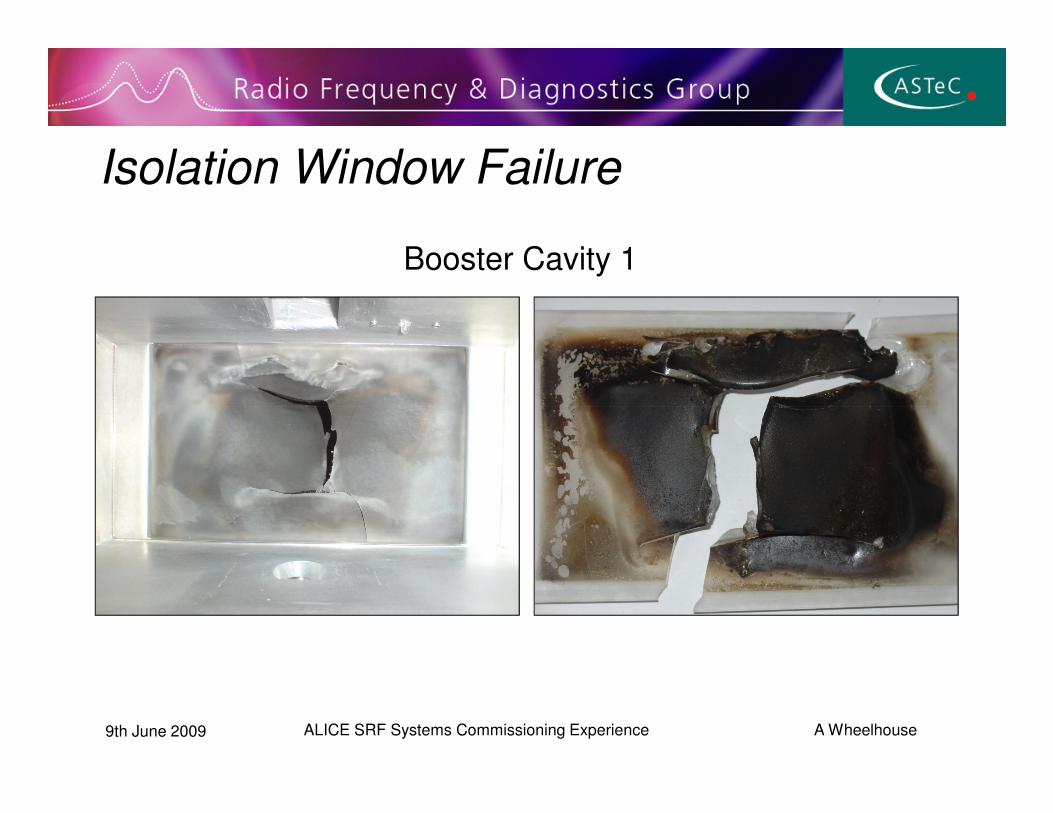
Isolation Window Failure
Booster Cavity 1
9th June 2009 ALICE SRF Systems Commissioning Experience A Wheelhouse

Window Failure Analysis
9th June 2009 ALICE SRF Systems Commissioning Experience A Wheelhouse

Inspection And Clean Up Process• Booster fully inspected and cleaned
• No obvious failure mechanism discovered
• Failure similar to one at Rossendorf– CW
• Arc marks noted on inner and outer conductor
9th June 2009 ALICE SRF Systems Commissioning Experience A Wheelhouse
conductor– Isolation vacuum events seen at low
RF power levels - ~1.5kW
• Linac inspected
• Improvements made to isolation vacuum interlocks
• Broadband RF detectors added to the reflected power monitoring

Booster Cavity Operation
9th June 2009 ALICE SRF Systems Commissioning Experience A Wheelhouse

Linac Cavity Operation
9th June 2009 ALICE SRF Systems Commissioning Experience A Wheelhouse

Beam Loading Issues• Initially beam loading seen at
6pC on Booster– Booster 1:
Qext 2.48x10⁶ �5.20x10⁵
– Booster 2:
Qext 2.61x10⁶ �8.97x10⁵ No beam loadingQext 2.61x10 �8.97x10
• Further beam loading– Train lengths > 50µS
– Bunch charges > 10pC
• Plans to improve LLRF feedback response times
• Optimisation of Qext
• Feed forward investigations
9th June 2009 ALICE SRF Systems Commissioning Experience A Wheelhouse
Beam loading

Energy Recovery – 20.8MeV
9th June 2009 ALICE SRF Systems Commissioning Experience A Wheelhouse

Future Plans• Short Term
– Cavity commissioning for ALICE operation• Analysis of quench points
– External Qs to be adjusted for 80pC operations– Investigation of LLRF limitations
• Improvement to response times of feedback loops
9th June 2009 ALICE SRF Systems Commissioning Experience A Wheelhouse
• Improvement to response times of feedback loops• Feed forward
• Long Term– Installation of a new 7-cell cryomodule
• Resolve high levels of field emission induced radiation
Summary
• Life of LLRF electronics extended by 100mm lead wall
• Reliability of HVPS and ancillary systems improved
9th June 2009 ALICE SRF Systems Commissioning Experience A Wheelhouse
• RF protection systems improved
• Energy Recovery achieved
• Beam loading seen for long pulse trains and high bunch charges– Investigations on going