aligning event logs and process models for multi...
TRANSCRIPT
Aligning Event Logs and Process Models forMulti-Perspective Conformance Checking: An
Approach Based on Integer Linear Programming
Massimiliano de Leoni and Wil M. P. van der Aalst
Eindhoven University of Technology, Eindhoven, The Netherlandsm.d.leoni,[email protected]
Abstract. Modern organizations have invested in collections of descriptive and/ornormative process models, but these rarely describe the actual processes ade-quately. Therefore, a variety of techniques for conformance checking have beenproposed to pinpoint discrepancies between modeled and observed behavior. How-ever, these techniques typically focus on the control-flow and abstract from data,resources and time. This paper describes an approach that aligns event log andmodel while taking all perspectives into account (i.e., also data, time and re-sources). This way it is possible to quantify conformance and analyze differencesbetween model and reality. The approach was implemented using ProM and hasbeen evaluated using both synthetic event logs and a real-life case study.
1 Introduction
Today’s organizations are challenged to make their processes more efficient and effec-tive; costs and response times need to be reduced in all of today’s industries. Processmodels are used to guide people, discuss process alternatives, and to automate partsof critical business processes. Often these process models are not enforced and peoplecan deviate from them. Such flexibility is often desirable, but still it is good to analyzedifferences between modeled and observed behavior. This illustrates the relevance ofconformance checking [1]. Conformance checking techniques take an event log and aprocess model and compare the observed traces with the traces possible according to themodel. There are different dimensions for comparing process models and event logs. Inthis paper, we focus of the fitness dimension: a model with good fitness allows for mostof the behavior seen in the event log. A model has perfect fitness if all traces in thelog can be replayed by the model from beginning to end. Other quality dimensions aresimplicity, precision, and generalization [1].
Various conformance checking techniques have been proposed in recent years [1–4]. Unfortunately, they focus on the control-flow, i.e. the ordering of activities, therebyignoring the other perspectives, such as data, resources, and time. In a process model,each case, i.e. a process instance, is characterized by its case variables. Paths takenduring the execution may be governed by guards and conditions defined over such vari-ables. Process models define the domain of possible values to assign to each variable,along with modeling the variables that each activity is prescribed to write or update. Inaddition, process models describe which resources are allowed to execute which activ-ities. An activity is typically associated with a particular role, i.e., a selected group ofresources. There may also be additional rules such as the “four-eyes principle” which
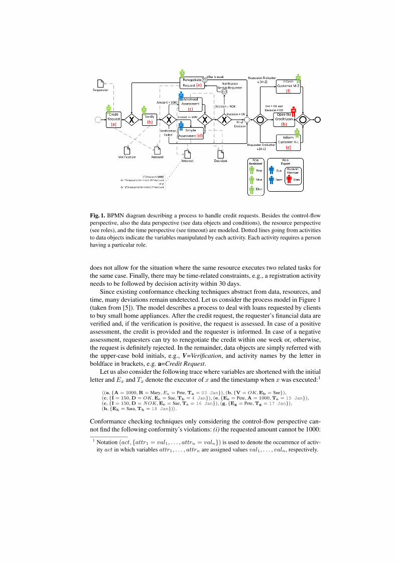
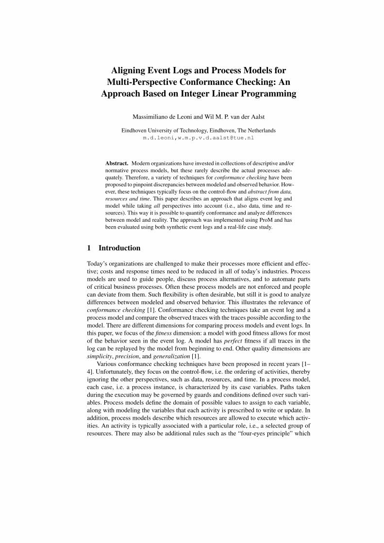
Fig. 1. BPMN diagram describing a process to handle credit requests. Besides the control-flowperspective, also the data perspective (see data objects and conditions), the resource perspective(see roles), and the time perspective (see timeout) are modeled. Dotted lines going from activitiesto data objects indicate the variables manipulated by each activity. Each activity requires a personhaving a particular role.
does not allow for the situation where the same resource executes two related tasks forthe same case. Finally, there may be time-related constraints, e.g., a registration activityneeds to be followed by decision activity within 30 days.
Since existing conformance checking techniques abstract from data, resources, andtime, many deviations remain undetected. Let us consider the process model in Figure 1(taken from [5]). The model describes a process to deal with loans requested by clientsto buy small home appliances. After the credit request, the requester’s financial data areverified and, if the verification is positive, the request is assessed. In case of a positiveassessment, the credit is provided and the requester is informed. In case of a negativeassessment, requesters can try to renegotiate the credit within one week or, otherwise,the request is definitely rejected. In the remainder, data objects are simply referred withthe upper-case bold initials, e.g., V=Verification, and activity names by the letter inboldface in brackets, e.g. a=Credit Request.
Let us also consider the following trace where variables are shortened with the initialletter and Ex and Tx denote the executor of x and the timestamp when x was executed:1
⟨(a, {A = 1000,R = Mary, Ea = Pete,Ta = 03 Jan}), (b, {V = OK,Eb = Sue}),(c, {I = 150,D = OK,Ec = Sue,Tb = 4 Jan}), (e, {Ee = Pete,A = 1000,Te = 15 Jan}),(c, {I = 150,D = NOK,Ec = Sue,Tc = 16 Jan}), (g, {Eg = Pete,Tg = 17 Jan}),(h, {Eh = Sara,Th = 18 Jan})⟩.
Conformance checking techniques only considering the control-flow perspective can-not find the following conformity’s violations: (i) the requested amount cannot be 1000:
1 Notation (act, {attr1 = val1, . . . , attrn = valn}) is used to denote the occurrence of activ-ity act in which variables attr1, . . . , attrn are assigned values val1, . . . , valn, respectively.
activity d should be executed, instead of c; (ii) for the considered credit loan, the inter-est is against the credit-institute’s policy for large loans; (iii) ‘Sue’ is not authorizedto execute activity b since she cannot play role Assistant; (iv) activity e is performed11 days after the preceding c occurrence, whereas it should not be later than 7 days;(v) activity h has been executed and, hence, the last decision cannot be negative. Theapproach we propose is based on the principle of finding an alignment of event log andprocess model. The events in the log traces are mapped to the execution of activitiesin the process model. Such an alignment shows how the event log can be replayed onthe process model. We allow costs to be assigned to every potential deviation: somedeviations may be more severe than others.
This paper proposes a technique based on building a suitable ILP program to finda valid sequence of activities that is as close as possible to the observed trace, i.e., weaim to minimize the cost of deviations and create an optimal alignment. To assess thepractical feasibility and relevance, the technique has also been implemented in ProM [6]and tested using synthetic event logs and in a real-life case study. Experimental resultsshow that conformance of the different perspectives can be checked efficiently.
When checking for conformance, pinpointing the deviations of every single traceis definitely useful, but it is not enough. Process analysts need to be provided with ahelicopter view of the conformance of the model with respect to the entire log. There-fore, this paper also introduces some diagnostics to clearly highlight the most frequentdeviations encountered during the process executions and the most common causes.
Our previous work [5] provides an initial approach for multi-perspective confor-mance checking. However, our previous technique could not deal with variables definedover infinite domains. The ILP-based approach presented in this paper also allows fornumerical values. Our new approach is also several orders of magnitude faster. Finally,the work reported in [5] was limited to returning optimal alignments. In this paper,we provide enhanced diagnostics guiding the user in finding the root-cause of specificconformance problems.
Our conformance-checking technique is independent of the specific formalism usedto describe the control-flow and data-flow perspectives. Therefore, BPMN, EPC or anyother formalism can be employed to represent these perspectives. However, we needa simple modeling language with clear semantics to explain our technique. For thispurpose we use Petri nets with data. The notation is briefly discussed in Section 2.Section 3 illustrates the basic concepts related to aligning a process and an event log.Section 5 details our new technique to compute optimal alignments and to provide en-hanced diagnostics. Section 6 describes the implementation in ProM and reports on theexperimental results. Finally, Section 7 concludes the paper, comparing this work withthe state of the art and describing future research directions.
2 Petri Nets with Data
A Petri net with data (DPN-net) is a Petri net in which transitions can write variables.This formalism was introduced in [7] and, later, revisited in [8]. A transition modelingan activity performs write operations on a given set of variables and may have a data-dependent guard. A transition can fire only if its guard is satisfied and all input places aremarked. A guard can be any formula over the process variables, using logical operatorssuch as conjunction (∧), disjunction (∨), and negation (¬).

Definition 1 (DPN-net). A Petri net with data (DPN-net) N = (P, T, F, V, U,W,G)consists of:
– a Petri net (P, T, F );– a set V of variables;– a function U that defines the values admissible, i.e., for each variable v ∈ V , U(v)
is the domain of variable v;– a write function W : T → 2V that labels each transition with a set of write opera-
tions, i.e. with a s the set of variables whose value needs to be written/updated;– a guard function G : T → GV that associates a guard with each transition.2
When a variable v ∈ V appears in a guard G(t), it refers to the value just before thet occurrence. Nonetheless, if v ∈ W (t), it can also appear as v′ (i.e., with the primesymbol). In this case, it refers to the value after the t occurrence. Some transitions canbe invisible and correspond to τ -steps: they do not represent actual pieces of work.Pictorially, they are represented as black boxes in the model.
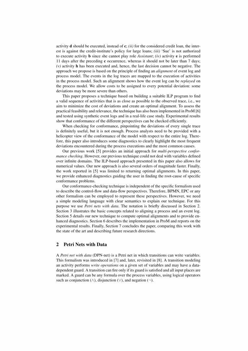
Example 1 Figure 2 shows the DPN-net that models the same process as that modeled in Fig-ure 1 through the BPMN notation. In particular, Figure 2(a) depicts the control-flow and the writeoperations. In addition to the variables depicted in the figure, there exists a set of variables tomodel the resource and time perspective, i.e., for each transition t, there are two variables Et
and Tt. Moreover, these two variables are associated with a write operation of t. Figure 2(b)enumerates the data-perspective guards Gd(t) for each transition t. When defining guards, weassume that string values can be lexicographically ordered and, hence, it is also possible to useinequality operators (i.e., < and >) for strings.
To also model the resource and time perspective, a second guard Gr(t) can be associatedwith each transition t (see Figure 2(c)). Formally, only one guard G(t) can be assigned to tand, hence, we set G(t) = Gd(t) ∧ Gr(t). Note the atom E′
c = Ec in the guard of transitionSimple Assessment in Figure 2(c): it models the resource constraint that the Simple Assessmentcannot be performed the i-th time by the same resource that performed it the (i − 1)-th timewithin the same case (i.e., the “four-eyes” principle mentioned in Section 1). Formula (T ′
e ≤Tc + 7days ∨ T ′
e ≤ Td + 7days) in the guard of transition Renegotiate Request to model that itmust occur within 7 days from the occurrence of the Assessment, Simple or Advanced. Conditionsare never satisfied when involving variables that are not set.
Space limitations prevent us from describing a complete operational semantics of DPN-net. Interested readers are referred to [8]. We only introduce the concepts needed later.The preset of a transition t is the set of its input places: •t = {p ∈ P | (p, t) ∈ F}. Thepostset of t is the set of its output places: t• = {p ∈ P | (t, p) ∈ F}. Definitions of pre-and postsets of places are analogous. A marking of a Petri net (with data) is a multisetof its places, i.e., a mapping M : P → N. We say the marking assigns to each place anumber of tokens. A state is a pair (M,A) where M is a marking for Petri net (P, T, F )and A is a function that associates a value with each variable, i.e. A : V → D ∪ {⊥},with A(v) ∈ U(v) ∪ {⊥}.3 Each DPN-net defines two special places po, pe ∈ P , theinitial and final place. The initial state is (M0, A0) where the initial place p0 ∈ Pcontains exactly one token, i.e. M0(p0) = 1, and any other p ∈ P \ {p0} contains notokens, i.e. M0(p) = 0. Moreover, A0(v) = ⊥ for each v ∈ V . A transition firings = (t, w) is valid in state (M,A) if each place in the preset of t contains at least one
2 The guard is defined over (a sub set of) variables in V . If a transition t has no guard, we setG(t) = true.
3 A special value ⊥ is assigned to variables that have not been initialized.
(a) The control-flow and write operations. Transitions and places are represented as squaresand circles, respectively. Each rounded orange rectangle identifies a different process vari-able. A dotted arrow from a transition t to a variable v is a pictorial representation of the factthat v ∈ W (t).
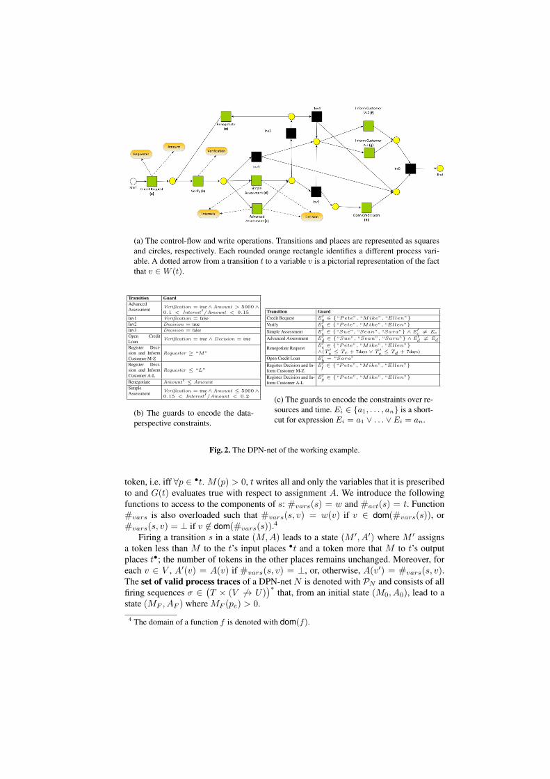
Transition GuardAdvancedAssessment Verification = true ∧Amount > 5000∧
0.1 < Interest′/Amount < 0.15
Inv1 Verification = falseInv2 Decision = trueInv3 Decision = falseOpen CreditLoan Verification = true ∧ Decision = true
Register Deci-sion and InformCustomer M-Z
Requester ≥ “M”
Register Deci-sion and InformCustomer A-L
Requester ≤ “L”
Renegotiate Amount′ ≤ Amount
SimpleAssessment Verification = true ∧Amount ≤ 5000∧
0.15 < Interest′/Amount < 0.2
(b) The guards to encode the data-perspective constraints.
Transition GuardCredit Request E′
a ∈ {“Pete”, “Mike”, “Ellen”}Verify E′
b ∈ {“Pete”, “Mike”, “Ellen”}Simple Assessment E′
c ∈ {“Sue”, “Sean”, “Sara”} ∧ E′c = Ec
Advanced Assessment E′d ∈ {“Sue”, “Sean”, “Sara”} ∧ E′
d = Ed
Renegotiate Request E′e ∈ {“Pete”, “Mike”, “Ellen”}
∧(T ′e ≤ Tc + 7days ∨ T ′
e ≤ Td + 7days)Open Credit Loan E′
h = “Sara”
Register Decision and In-form Customer M-Z
E′f ∈ {“Pete”, “Mike”, “Ellen”}
Register Decision and In-form Customer A-L
E′g ∈ {“Pete”, “Mike”, “Ellen”}
(c) The guards to encode the constraints over re-sources and time. Ei ∈ {a1, . . . , an} is a short-cut for expression Ei = a1 ∨ . . . ∨ Ei = an.
Fig. 2. The DPN-net of the working example.
token, i.e. iff ∀p ∈ •t. M(p) > 0, t writes all and only the variables that it is prescribedto and G(t) evaluates true with respect to assignment A. We introduce the followingfunctions to access to the components of s: #vars(s) = w and #act(s) = t. Function#vars is also overloaded such that #vars(s, v) = w(v) if v ∈ dom(#vars(s)), or#vars(s, v) = ⊥ if v ∈ dom(#vars(s)).4
Firing a transition s in a state (M,A) leads to a state (M ′, A′) where M ′ assignsa token less than M to the t’s input places •t and a token more that M to t’s outputplaces t•; the number of tokens in the other places remains unchanged. Moreover, foreach v ∈ V , A′(v) = A(v) if #vars(s, v) = ⊥, or, otherwise, A(v′) = #vars(s, v).The set of valid process traces of a DPN-net N is denoted with PN and consists of allfiring sequences σ ∈
(T × (V → U)
)∗ that, from an initial state (M0, A0), lead to astate (MF , AF ) where MF (pe) > 0.
4 The domain of a function f is denoted with dom(f).
A DPN-net is data sound iff, for each sequence of transitions yielding a token in thefinal place, there is a sequence of write operations for the transitions in the sequencesuch that the guard of every transition t in the sequence is satisfied when t fires.
Definition 2 (Data Soundness). Let N = (P, T, F, V, U,W,G) be a DPN-net. LetN ′ = (P, T, F,∅, U ′,W ′, G′) be a DPN-net such that dom(U ′) = dom(W ′) =dom(G′) = ∅. DPN-net N is data sound iff, for each ⟨s′1, . . . , s′n⟩ ∈ PN ′ , there existsa sequence ⟨s1, . . . , sn⟩ ∈ PN where, for all 1 ≤ i ≤ n, #act(si) = #act(s
′i).
3 Alignments of Event Logs and Process Models
An event log contains events associated to cases, i.e., process instances. Each case fol-lows a trace of events. Each trace records the execution of a process instance. Differentinstances may follow the same trace. Let SN be the set of (valid and invalid) firing oftransitions of a DPN-net N with SN . An event log is a multi-set of traces: L ∈ B(S∗
N ).5
Conformance checking requires an alignment of event log L and process model P:the events in the event log need to be related to model elements and vice versa. Such analignment shows how the event log can be replayed on the process model. This is farfrom being trivial since the log may deviate from the model and not all activities mayhave been modeled and recorded.
We need to relate “moves” in the log to “moves” in the model in order to establishan alignment between a process model and an event log. However, it may be the casethat some of the moves in the log cannot be mimicked by the model and vice versa.We explicitly denote “no move” by ≫. For convenience, we introduce the set S⊥
N =SN ∪ {≫}.
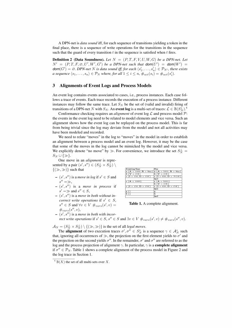
Event-Log Trace Proca {A = 1000,R = Mary} a {A = 5001,R = Mary}b {V = OK) b {V = OK}c {I = 150,D = OK} c {I = 650,D = NOK}
Inv3e {A = 1000} e {A = 5001}
b {V = OK}c {I = 150,D = OK} c {I = 650,D = OK}
Inv2g {} gh {} h
Inv5
Table 1. A complete alignment.
One move in an alignment is repre-sented by a pair (s′, s′′) ∈ (S⊥
N × S⊥N ) \
{(≫,≫)} such that
– (s′, s′′) is a move in log if s′ ∈ S ands′′ =≫,
– (s′, s′′) is a move in process ifs′ =≫ and s′′ ∈ S,
– (s′, s′′) is a move in both without in-correct write operations if s′ ∈ S,s′′ ∈ S and ∀v ∈ V #vars(s
′, v) =#vars(s
′′, v),– (s′, s′′) is a move in both with incor-
rect write operations if s′ ∈ S, s′′ ∈ S and ∃v ∈ V #vars(s′, v) = #vars(s
′′, v).
AN = (S⊥N × S⊥
N ) \ {(≫,≫)} is the set of all legal moves.The alignment of two execution traces σ′, σ′′ ∈ S∗
N is a sequence γ ∈ A∗N such
that, ignoring all occurrences of ≫, the projection on the first element yields to σ′ andthe projection on the second yields σ′′. In the remainder, σ′ and σ′′ are referred to as thelog and the process projection of alignment γ. In particular, γ is a complete alignmentif σ′′ ∈ PN . Table 1 shows a complete alignment of the process model in Figure 2 andthe log trace in Section 1.
5 B(X) the set of all multi-sets over X .
In order to define the severity of a deviation, we introduce a cost function on legalmoves: κ ∈ SA → R+
0 . The cost of each legal move depends on the specific modeland process domain and, hence, cost function κ needs to be defined ad-hoc for everyspecific case. The cost function can be generalized to an alignment γ as the sum of thecost of each individual move: K(γ) =
∑(s′,s′′)∈γ κ(s
′, s′′).
However, we do not aim to find any complete alignment. Given a log trace σL ∈ L,our goal is to find a complete alignment of σL and P which minimizes the cost. Werefer to it as an optimal alignment. Let ΓσL,P be the multi-set of all complete align-ments of σL and P . The alignment γ ∈ ΓσL,P is an optimal alignment if ∀γ′ ∈ΓσL,P K(γ) ≤ K(γ′). Note that there may exist several optimal alignments, i.e. severalcomplete alignments having the same minimal cost.
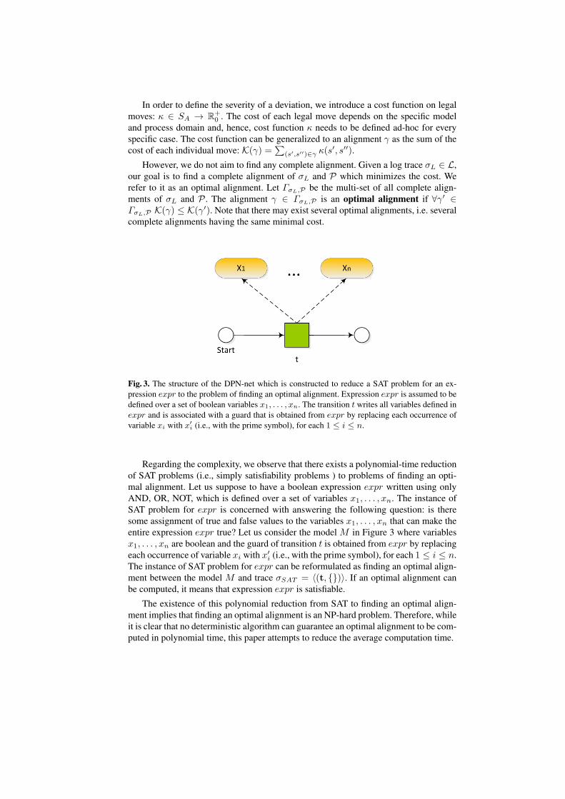
Fig. 3. The structure of the DPN-net which is constructed to reduce a SAT problem for an ex-pression expr to the problem of finding an optimal alignment. Expression expr is assumed to bedefined over a set of boolean variables x1, . . . , xn. The transition t writes all variables defined inexpr and is associated with a guard that is obtained from expr by replacing each occurrence ofvariable xi with x′
i (i.e., with the prime symbol), for each 1 ≤ i ≤ n.
Regarding the complexity, we observe that there exists a polynomial-time reductionof SAT problems (i.e., simply satisfiability problems ) to problems of finding an opti-mal alignment. Let us suppose to have a boolean expression expr written using onlyAND, OR, NOT, which is defined over a set of variables x1, . . . , xn. The instance ofSAT problem for expr is concerned with answering the following question: is theresome assignment of true and false values to the variables x1, . . . , xn that can make theentire expression expr true? Let us consider the model M in Figure 3 where variablesx1, . . . , xn are boolean and the guard of transition t is obtained from expr by replacingeach occurrence of variable xi with x′
i (i.e., with the prime symbol), for each 1 ≤ i ≤ n.The instance of SAT problem for expr can be reformulated as finding an optimal align-ment between the model M and trace σSAT = ⟨(t, {})⟩. If an optimal alignment canbe computed, it means that expression expr is satisfiable.
The existence of this polynomial reduction from SAT to finding an optimal align-ment implies that finding an optimal alignment is an NP-hard problem. Therefore, whileit is clear that no deterministic algorithm can guarantee an optimal alignment to be com-puted in polynomial time, this paper attempts to reduce the average computation time.
4 Integer Linear Programming
Integer Linear programming (ILP) can be used to solve so-called linear optimizationproblems. Let {x1, . . . , xn} be a set of variables, each of which can be boolean, con-tinuous or integer. ILP problems can be formulated as follows:
1. A linear function f(·) to be maximized/minimized.
max /min f(x1, . . . , xn)
2. A set of m linear constraints, with m finite.
a11x1 + . . .+ a1nxn ≤ b1...
...am1x1 + . . .+ amnxn ≤ bm
Other forms, such as problems with constraints of different forms, can always be rewrit-ten into an equivalent problem in this form. For instance, an equality constraint a11x1+. . .+a1nxn = b1 can be replaced with two inequality constraints: a11x1+. . .+a1nxn ≤b1 and −a11x1 − . . .− a1nxn ≤ −b1. A constraint a11x1 + . . .+ a1nxn < b1 can bereplaced with a11x1 + . . .+ a1nxn ≤ b1 − ϵ, where ϵ is a sufficiently small number.
ILP problems assume variables to be numerical (integers or reals) and boolean, withboolean variables represented as integers assignable either value 0 or 1. Nonetheless,dates and strings can also be taken into account by converting them into numerical val-ues. A date can be converted into an integer value, e.g., that denotes the number ofmilliseconds elapsed from a reference timestamp, usually 1 January, 1970. A stringscan be considered as base-256 numbers (256 is the number of different ASCII charac-ters) where the first character is the least significative. The conversion of such base-256numbers to base-10 provides the conversion of strings to numerical values. This mech-anism of converting strings and dates are clearly bidirectional and, for strings, it alsopreserves its natural lexicographical ordering.
5 The ILP-based Technique and Diagnostics
In order to find an optimal alignment of a DPN net N = (P, T, F, V, U,W,G) and a logtrace σL, we rely on existing techniques to build an alignment that only considers thecontrol-flow perspective. Later, we construct a problem of Integer Linear Programming(ILP) to obtain an optimal alignment which also take the other process perspectives intoaccount.
The approach assumes four functions to be provided by process analysts. Functionsκl(t) and κp(t) return a non-negative cost associated with a move in log or process fortransition t. Function kv(v) returns a non-negative cost relative to a variable v and amove in both (sLi , s
Pi ) where #vars(s
Li , v) = ⊥ and #vars(s
Li , v) = #vars(s
Pi , v)
(i.e., sLi assigns to v a value that is out of the domain or incompatible with some guard).Function kn(v) returns a non-negative cost relative to a variable v and a move in both(sLi , s
Pi ) where #vars(s
Li , v) = ⊥ and #vars(s
Pi , v) = ⊥ (i.e., sLi does not perform
a prescribed write operation for v). These four functions can be suitably composed toobtain cost functions κ as defined in Section 3. Our ILP-based technique comprises ofthree phases:

1. We employ the off-the-shelf techniques described in [9] to build an alignment γC =⟨(sL1 , sP1 ), . . . , (sLn , sPn )⟩ between the Petri net (P, T, F ) and the log trace σL usingthe cost functions kl and km. Since such techniques only take the control-flowinto account, the process projection of γC does not contain write operations, i.e. ifsPi =≫, dom(#vars(s
Pi )) = ∅ for all 1 ≤ i ≤ n.6 In the remainder, γC is called
control-flow alignment and is not a complete alignment since its process projectionis not a trace in PN .
2. We enrich the firings of transitions in the process projection σC of γC with theopportune write operations so as to minimize their difference with respect to thewrite operations observed in σL. Since it is a minimization problem, finding theopportune write operations can be formulated as solving a certain ILP problem:when a solution is found, the values of certain variables of the ILP-problem denotethose to be assigned to variables in the writing operations of σC . The ILP-problemobjective function f is the alignment cost.
3. We compute the fitness value F(σL) ∈ [0, 1]. Adriansyah et al. [9] propose afitness measurement where only the control-flow is considered. Let FC(σL) ∈[0, 1] be this measure. Here, we propose a fitness with respect to all perspectives:F(σL) =
(FD(σL) + FC(σL)
)/2 which is the mean of FC(σL) and a certain
quantity FD(σL) ∈ [0, 1] that considers the fitness with respect to any of the non-control-flow perspectives (data, resource, time):
FD(σL) =fmin∑
(sL,sP )∈γO : sP =≫∑
v∈#vars(sP ) max(kd(v), kn(v))
where fmin is the value of the objective function for the solution found of the ILPproblem. The denominator corresponds to the highest cost in term of deviations,i.e. for each move (sL, sP ) in both, the deviations between the write operations ofsL and sP have the highest cost.
Section 5.1 details how a ILP problem can be constructed to find an optimal alignmentof a log trace and a process model. To keep the discussion simple, each guard is assumedto be atomic (e.g., Amount > 5000). However, this limitation can be easily addressed,as discussed in Section 5.2.
Section 1 already mentioned the need to provide a helicopter view which showscommon deviations and their causes. Section 5.3 discusses our proposal to aggregate theinformation associated to the optimal alignments and visualize the deviations upon theprocess model. Moreover, process analyst can inspect the usual conditions when certaindeviations occur: each transition is associated with a decision tree which classifies thetypes of deviations as function of the process state when the deviation has occurred.
5.1 Construction of the ILP problem
Given a DPN-net N and a log trace σL, the outcome of the first phase is a control-flowalignment γC = ⟨(sL1 , sP1 ), . . . , (sLn , sPn )⟩.
Example 2 In order to maintain the example of a reasonable size, in the remainder, we onlyconsider the data perspective (i.e., we ignore the guards in Figure 2(c)). Let us assume κl(t) =
6 the domain of a function f is denoted with dom(f)
Event-Log Trace Proca {A = 1000, R = Mary} ab {V = OK) bc {I = 150,D = OK} c
Inv3e {A = 1000} e
bc {I = 150,D = NOK} c
Inv2g {} gh {} h
Inv5
(a) Control-flowAlignment.
min 10 + V1 + I1 + D1 + A1+A2 + I2 + D2 + R1
V1 = 1I1 > 0.1 A1I1 < 0.15 A1D1 = 0A2 < 0.6 A1I2 > 0.1 A2I2 < 0.1 A2I2 < 0.15 A2D2 = 0R1 < “M”
A1 = 1000 ⇔ A1 = 0
R1 = “Mary” ⇔ R1 = 0
I1 = 150 ⇔ I1 = 0
A2 = 1000 ⇔ A1 = 0
I2 = 150 ⇔ I2 = 0
D2 = 1 ⇔ D2 = 0
(b) The ILP problem tofind an optimal alignment.
Event-Log Trace Proca {A = 1000,R = Mary} a {A = A∗
1 ,R = R∗1}
b {V = OK) b {V = V ∗1 }
c {I = 150,D = OK} c {I = I∗1 ,D = D∗1}
Inv3e {A = 1000} e {A = A∗
2}b {V = V ∗
2 }c {I = 150,D = NOK} c {I = I∗2 ,D = D∗
2}Inv2
g {} gh {} h
Inv5
(c) Optimal Alignment obtained assolution of an ILP problem: v∗i de-notes the value assigned to variablevi in the ILP-problem solution thatis found.
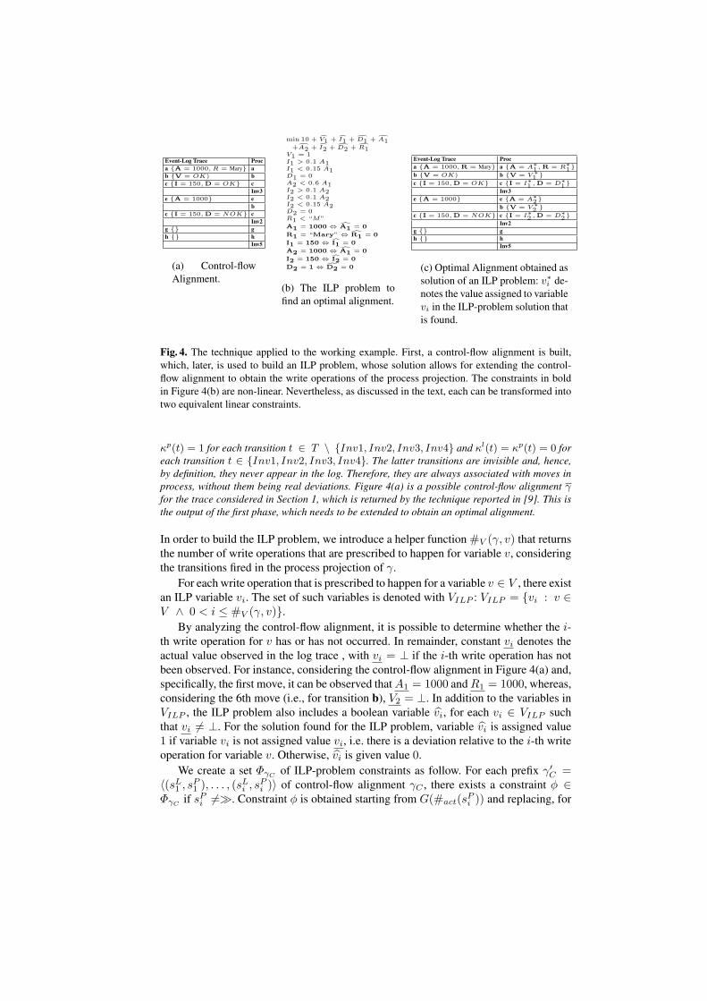
Fig. 4. The technique applied to the working example. First, a control-flow alignment is built,which, later, is used to build an ILP problem, whose solution allows for extending the control-flow alignment to obtain the write operations of the process projection. The constraints in boldin Figure 4(b) are non-linear. Nevertheless, as discussed in the text, each can be transformed intotwo equivalent linear constraints.
κp(t) = 1 for each transition t ∈ T \ {Inv1, Inv2, Inv3, Inv4} and κl(t) = κp(t) = 0 foreach transition t ∈ {Inv1, Inv2, Inv3, Inv4}. The latter transitions are invisible and, hence,by definition, they never appear in the log. Therefore, they are always associated with moves inprocess, without them being real deviations. Figure 4(a) is a possible control-flow alignment γfor the trace considered in Section 1, which is returned by the technique reported in [9]. This isthe output of the first phase, which needs to be extended to obtain an optimal alignment.
In order to build the ILP problem, we introduce a helper function #V (γ, v) that returnsthe number of write operations that are prescribed to happen for variable v, consideringthe transitions fired in the process projection of γ.
For each write operation that is prescribed to happen for a variable v ∈ V , there existan ILP variable vi. The set of such variables is denoted with VILP : VILP = {vi : v ∈V ∧ 0 < i ≤ #V (γ, v)}.
By analyzing the control-flow alignment, it is possible to determine whether the i-th write operation for v has or has not occurred. In remainder, constant vi denotes theactual value observed in the log trace , with vi = ⊥ if the i-th write operation has notbeen observed. For instance, considering the control-flow alignment in Figure 4(a) and,specifically, the first move, it can be observed that A1 = 1000 and R1 = 1000, whereas,considering the 6th move (i.e., for transition b), V2 = ⊥. In addition to the variables inVILP , the ILP problem also includes a boolean variable vi, for each vi ∈ VILP suchthat vi = ⊥. For the solution found for the ILP problem, variable vi is assigned value1 if variable vi is not assigned value vi, i.e. there is a deviation relative to the i-th writeoperation for variable v. Otherwise, vi is given value 0.
We create a set ΦγCof ILP-problem constraints as follow. For each prefix γ′
C =⟨(sL1 , sP1 ), . . . , (sLi , sPi )⟩ of control-flow alignment γC , there exists a constraint ϕ ∈ΦγC
if sPi =≫. Constraint ϕ is obtained starting from G(#act(sPi )) and replacing, for
each v ∈ V , all occurrences of v with vk−1 ∈ VILP and all occurrences of v′ (i.e., withthe prime symbol) with vk ∈ VILP , where k = #V (γ
′C , v).
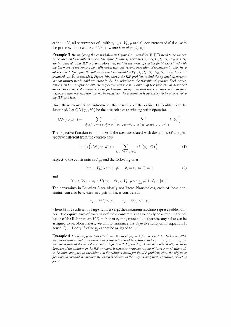
Example 3 By analyzing the control-flow in Figure 4(a), variables V, I,D need to be writtentwice each and variable R once. Therefore, following variables V1, V2, I1, I2, D1, D2 and R1
are introduced to the ILP problem. Moreover, besides the write operation for V associated withthe 6th move of the control-flow alignment (i.e., the second execution of transition b), they haveall occurred. Therefore the following boolean variables V1, , I1, I2, D1, D2, R1 needs to be in-troduced, i.e. V2 is excluded. Figure 4(b) shows the ILP problem to find the optimal alignment:the constraints not in bold are those in Φγ , i.e. relative to the transitions’ guards. Each occur-rence v and v′ is replaced with the respective variable vi−1 and vi of ILP problem, as describedabove. To enhance the example’s comprehension, string constants are not converted into theirrespective numeric representations. Nonetheless, the conversion is necessary to be able to solvethe ILP problem.
Once these elements are introduced, the structure of the entire ILP problem can bedescribed. Let CN(γC , k
n) be the cost relative to missing write operations:
CN(γC , kn) =
∑(sLi ,sPi )∈γC s.t. sPi =≫
( ∑v∈(dom(#vars(sPi ))\dom(#vars(sLi )))
kn(v))
The objective function to minimize is the cost associated with deviations of any per-spective different from the control-flow:
min(CN(γC , k
n) +∑
vi∈VILP :vi =⊥
(kd(v) · vi
))(1)
subject to the constraints in ΦγCand the following ones:
∀vi ∈ VILP s.t. vi = ⊥. vi = vi ⇔ vi = 0 (2)
and∀vi ∈ VILP . vi ∈ U(v); ∀vi ∈ VILP s.t. vi = ⊥. vi ∈ [0, 1]
The constraints in Equation 2 are clearly not linear. Nonetheless, each of these con-straints can also be written as a pair of linear constraints:
vi −Mvi ≤ vi; −vi −Mvi ≤ −vi
where M is a sufficiently large number (e.g., the maximum machine-representable num-ber). The equivalence of each pair of these constraints can be easily observed: in the so-lution of the ILP problem, if vi = 0, then vi = vi must hold; otherwise any value can beassigned to vi. Nonetheless, we aim to minimize the objective function in Equation 1;hence, vi = 1 only if value vi cannot be assigned to vi.
Example 4 Let us suppose that kn(v) = 10 and kd(v) = 1 for each v ∈ V . In Figure 4(b),the constraints in bold are those which are introduced to enforce that vi = 0 iff vi = vi, i.e.the constraints of the type described in Equation 2. Figure 4(c) shows the optimal alignment infunction of the solution of the ILP problem. It contains write operations of form v = v∗i where v∗iis the value assigned to variable vi in the solution found for the ILP problem. Note the objectivefunction has an added constant 10, which is relative to the only missing write operation, which isfor V .
The following theorem discusses the admissibility of the ILP problems constructed asdescribed above and, hence, the conditions under which an optimal alignment exists:
Theorem 1 (Admissibility of the ILP problem). Let N = (P, T, F, V, U,W,G) be adata-sound DPN-Net and σL be a log trace. The ILP problem constructed as mentionedabove to find an optimal alignment of σL and N is always admissible.
Proof (Sketch). Let us construct the DPN-net N ′ = (P, T, F,∅, U ′,W ′, G′) wheredom(U ′) = dom(W ′) = dom(G′) = ∅. Let σC = ⟨(a1, w0), . . . , (an, w0)⟩ be theprocess projection of the control-flow alignment between N and σL, i.e. dom(w0) = ∅.Since no variable is defined in N ′, σC ∈ PN ′ . DPN-net N is data sound and, hence,there must exist a set {w1, . . . , wn} such that σP = ⟨(a1, w1), . . . , (an, wn)⟩ ∈ PN .If σP exists, there also exists a complete alignment of which traces σP and σL are theprocess and log projection. Therefore, at least one complete alignment exists, which canbe obtained as solution of the ILP problem. Therefore, a solution of the ILP problemexists. ⊓⊔
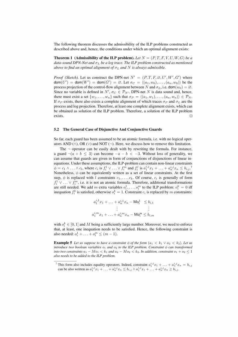
5.2 The General Case of Disjunctive And Conjunctive Guards
So far, each guard has been assumed to be an atomic formula, i.e. with no logical oper-ators AND (∧), OR (∨) and NOT (¬). Here, we discuss how to remove this limitation.
The ¬ operator can be easily dealt with by rewriting the formula. For instance,a guard ¬(a + b ≤ 3) can become −a − b < −3. Without loss of generality, wecan assume that guards are given in form of conjunctions of disjunctions of linear in-equations. Under these assumptions, the ILP-problem can contain non-linear constraintsϕ = c1 ∧ . . . ∧ cl, where ci is f1
i ∨ . . . ∨ fmi and f j
i is ai,j1 x1 + . . . + ai,jn xn ≤ bi,j .7
Nonetheless, ϕ can be equivalently written as a set of linear constraints. At the firststep, ϕ is replaced with l constraints c1, . . . , ck. Of course, ci is generally of formf1i ∨ . . . ∨ fm
i , i.e. it is not an atomic formula. Therefore, additional transformationsare still needed. We add m extra variables o1i , . . . , o
mi to the ILP problem: oki = 0 iff
inequation fki is satisfied, otherwise oki = 1. Constraint ci is replaced by m constraints:
ai,11 x1 + . . .+ ai,1n xn −Mo1i ≤ bi,1...
...ai,m1 x1 + . . .+ ai,mn xn −Momi ≤ bi,m
with oki ∈ [0, 1] and M being a sufficiently large number. Moreover, we need to enforcethat, at least, one inequation needs to be satisfied. Hence, the following constraint isalso needed: o1i + . . .+ omi ≤ (m− 1).
Example 5 Let us suppose to have a constraint ϕ of the form (a1 < k1 ∨ a2 < k2). Let usintroduce two boolean variables o1 and o2 to the ILP problem. Constraint ϕ can transformedinto two constraints a1 −Mo1 < k1 and a2 −Mo2 < k2. In addition, constraint o1 + o2 ≤ 1also needs to be added to the ILP problem.
7 This form also includes equality operators. Indeed, constraint ai,j1 x1 + . . . + ai,j
n xn = bi,jcan be also written as ai,j
1 x1 + . . .+ ai,jn xn ≤ bi,j ∧ ai,j
1 x1 + . . .+ ai,jn xn ≥ bi,j .
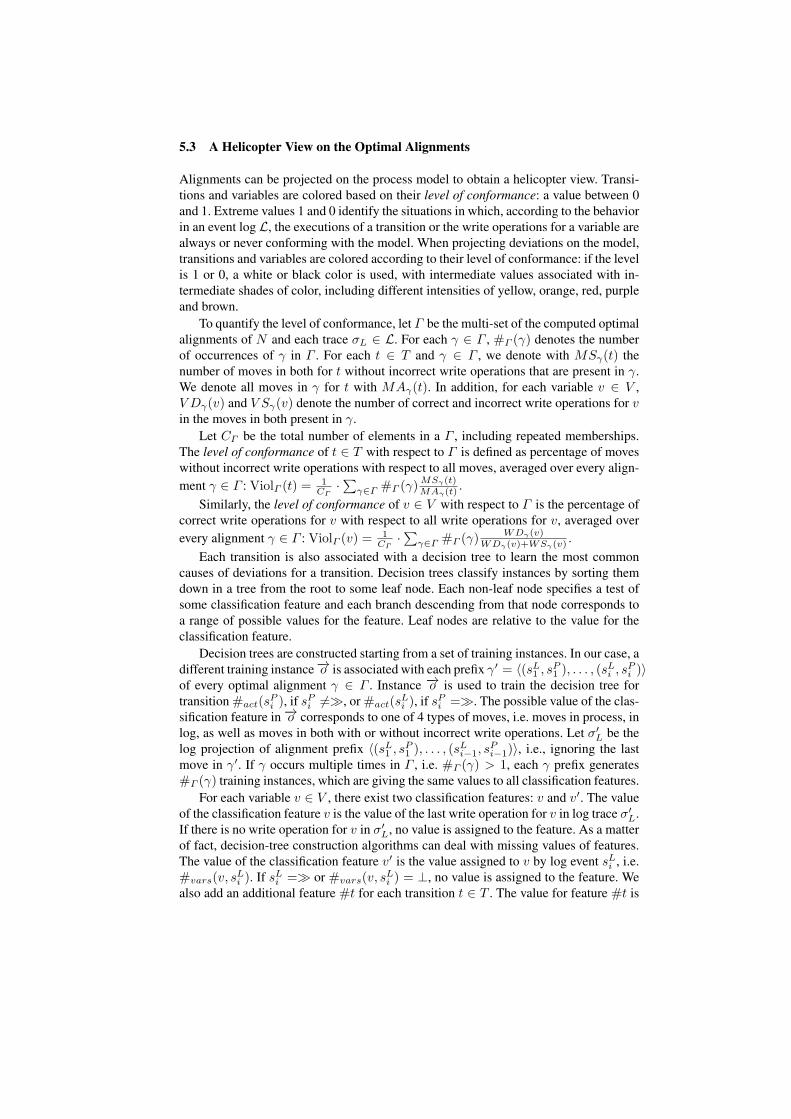
5.3 A Helicopter View on the Optimal Alignments
Alignments can be projected on the process model to obtain a helicopter view. Transi-tions and variables are colored based on their level of conformance: a value between 0and 1. Extreme values 1 and 0 identify the situations in which, according to the behaviorin an event log L, the executions of a transition or the write operations for a variable arealways or never conforming with the model. When projecting deviations on the model,transitions and variables are colored according to their level of conformance: if the levelis 1 or 0, a white or black color is used, with intermediate values associated with in-termediate shades of color, including different intensities of yellow, orange, red, purpleand brown.
To quantify the level of conformance, let Γ be the multi-set of the computed optimalalignments of N and each trace σL ∈ L. For each γ ∈ Γ , #Γ (γ) denotes the numberof occurrences of γ in Γ . For each t ∈ T and γ ∈ Γ , we denote with MSγ(t) thenumber of moves in both for t without incorrect write operations that are present in γ.We denote all moves in γ for t with MAγ(t). In addition, for each variable v ∈ V ,V Dγ(v) and V Sγ(v) denote the number of correct and incorrect write operations for vin the moves in both present in γ.
Let CΓ be the total number of elements in a Γ , including repeated memberships.The level of conformance of t ∈ T with respect to Γ is defined as percentage of moveswithout incorrect write operations with respect to all moves, averaged over every align-ment γ ∈ Γ : ViolΓ (t) =
1CΓ
·∑
γ∈Γ #Γ (γ)MSγ(t)MAγ(t)
.
Similarly, the level of conformance of v ∈ V with respect to Γ is the percentage ofcorrect write operations for v with respect to all write operations for v, averaged overevery alignment γ ∈ Γ : ViolΓ (v) = 1
CΓ·∑
γ∈Γ #Γ (γ)WDγ(v)
WDγ(v)+WSγ(v).
Each transition is also associated with a decision tree to learn the most commoncauses of deviations for a transition. Decision trees classify instances by sorting themdown in a tree from the root to some leaf node. Each non-leaf node specifies a test ofsome classification feature and each branch descending from that node corresponds toa range of possible values for the feature. Leaf nodes are relative to the value for theclassification feature.
Decision trees are constructed starting from a set of training instances. In our case, adifferent training instance −→o is associated with each prefix γ′ = ⟨(sL1 , sP1 ), . . . , (sLi , sPi )⟩of every optimal alignment γ ∈ Γ . Instance −→o is used to train the decision tree fortransition #act(s
Pi ), if sPi =≫, or #act(s
Li ), if sPi =≫. The possible value of the clas-
sification feature in −→o corresponds to one of 4 types of moves, i.e. moves in process, inlog, as well as moves in both with or without incorrect write operations. Let σ′
L be thelog projection of alignment prefix ⟨(sL1 , sP1 ), . . . , (sLi−1, s
Pi−1)⟩, i.e., ignoring the last
move in γ′. If γ occurs multiple times in Γ , i.e. #Γ (γ) > 1, each γ prefix generates#Γ (γ) training instances, which are giving the same values to all classification features.
For each variable v ∈ V , there exist two classification features: v and v′. The valueof the classification feature v is the value of the last write operation for v in log trace σ′
L.If there is no write operation for v in σ′
L, no value is assigned to the feature. As a matterof fact, decision-tree construction algorithms can deal with missing values of features.The value of the classification feature v′ is the value assigned to v by log event sLi , i.e.#vars(v, s
Li ). If sLi =≫ or #vars(v, s
Li ) = ⊥, no value is assigned to the feature. We
also add an additional feature #t for each transition t ∈ T . The value for feature #t is
the number of firings of transition t in σ′L, i.e. the number of execution of t before the
last move of γ′.
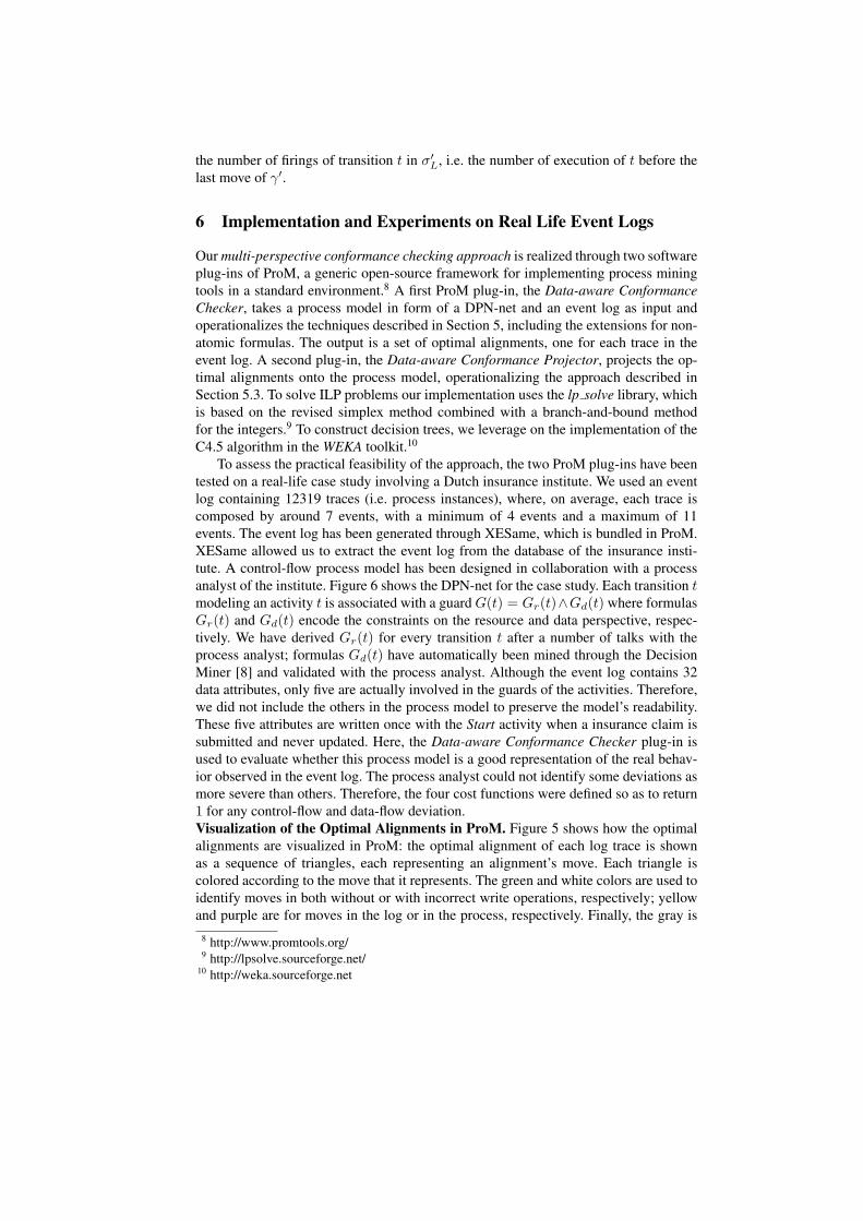
6 Implementation and Experiments on Real Life Event Logs
Our multi-perspective conformance checking approach is realized through two softwareplug-ins of ProM, a generic open-source framework for implementing process miningtools in a standard environment.8 A first ProM plug-in, the Data-aware ConformanceChecker, takes a process model in form of a DPN-net and an event log as input andoperationalizes the techniques described in Section 5, including the extensions for non-atomic formulas. The output is a set of optimal alignments, one for each trace in theevent log. A second plug-in, the Data-aware Conformance Projector, projects the op-timal alignments onto the process model, operationalizing the approach described inSection 5.3. To solve ILP problems our implementation uses the lp solve library, whichis based on the revised simplex method combined with a branch-and-bound methodfor the integers.9 To construct decision trees, we leverage on the implementation of theC4.5 algorithm in the WEKA toolkit.10
To assess the practical feasibility of the approach, the two ProM plug-ins have beentested on a real-life case study involving a Dutch insurance institute. We used an eventlog containing 12319 traces (i.e. process instances), where, on average, each trace iscomposed by around 7 events, with a minimum of 4 events and a maximum of 11events. The event log has been generated through XESame, which is bundled in ProM.XESame allowed us to extract the event log from the database of the insurance insti-tute. A control-flow process model has been designed in collaboration with a processanalyst of the institute. Figure 6 shows the DPN-net for the case study. Each transition tmodeling an activity t is associated with a guard G(t) = Gr(t)∧Gd(t) where formulasGr(t) and Gd(t) encode the constraints on the resource and data perspective, respec-tively. We have derived Gr(t) for every transition t after a number of talks with theprocess analyst; formulas Gd(t) have automatically been mined through the DecisionMiner [8] and validated with the process analyst. Although the event log contains 32data attributes, only five are actually involved in the guards of the activities. Therefore,we did not include the others in the process model to preserve the model’s readability.These five attributes are written once with the Start activity when a insurance claim issubmitted and never updated. Here, the Data-aware Conformance Checker plug-in isused to evaluate whether this process model is a good representation of the real behav-ior observed in the event log. The process analyst could not identify some deviations asmore severe than others. Therefore, the four cost functions were defined so as to return1 for any control-flow and data-flow deviation.Visualization of the Optimal Alignments in ProM. Figure 5 shows how the optimalalignments are visualized in ProM: the optimal alignment of each log trace is shownas a sequence of triangles, each representing an alignment’s move. Each triangle iscolored according to the move that it represents. The green and white colors are used toidentify moves in both without or with incorrect write operations, respectively; yellowand purple are for moves in the log or in the process, respectively. Finally, the gray is
8 http://www.promtools.org/9 http://lpsolve.sourceforge.net/
10 http://weka.sourceforge.net
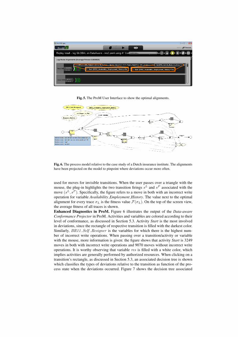
Fig. 5. The ProM User Interface to show the optimal alignments.
Fig. 6. The process model relative to the case study of a Dutch insurance institute. The alignmentshave been projected on the model to pinpoint where deviations occur more often.
used for moves for invisible transitions. When the user passes over a triangle with themouse, the plug-in highlights the two transition firings sL and sP associated with themove (sL, sP ). Specifically, the figure refers to a move in both with an incorrect writeoperation for variable Availability Employment History. The value next to the optimalalignment for every trace σL is the fitness value F(σL). On the top of the screen view,the average fitness of all traces is shown.Enhanced Diagnostics in ProM. Figure 6 illustrates the output of the Data-awareConformance Projector in ProM. Activities and variables are colored according to theirlevel of conformance, as discussed in Section 5.3. Activity Start is the most involvedin deviations, since the rectangle of respective transition is filled with the darkest color.Similarly, BR11 Self Resigner is the variables for which there is the highest num-ber of incorrect write operations. When passing over a transition/activity or variablewith the mouse, more information is given: the figure shows that activity Start is 3249moves in both with incorrect write operations and 9070 moves without incorrect writeoperations. It is worthy observing that variable res is filled with a white color, whichimplies activities are generally performed by authorized resources. When clicking on atransition’s rectangle, as discussed in Section 5.3, an associated decision tree is shownwhich classifies the types of deviations relative to the transition as function of the pro-cess state when the deviations occurred. Figure 7 shows the decision tree associated
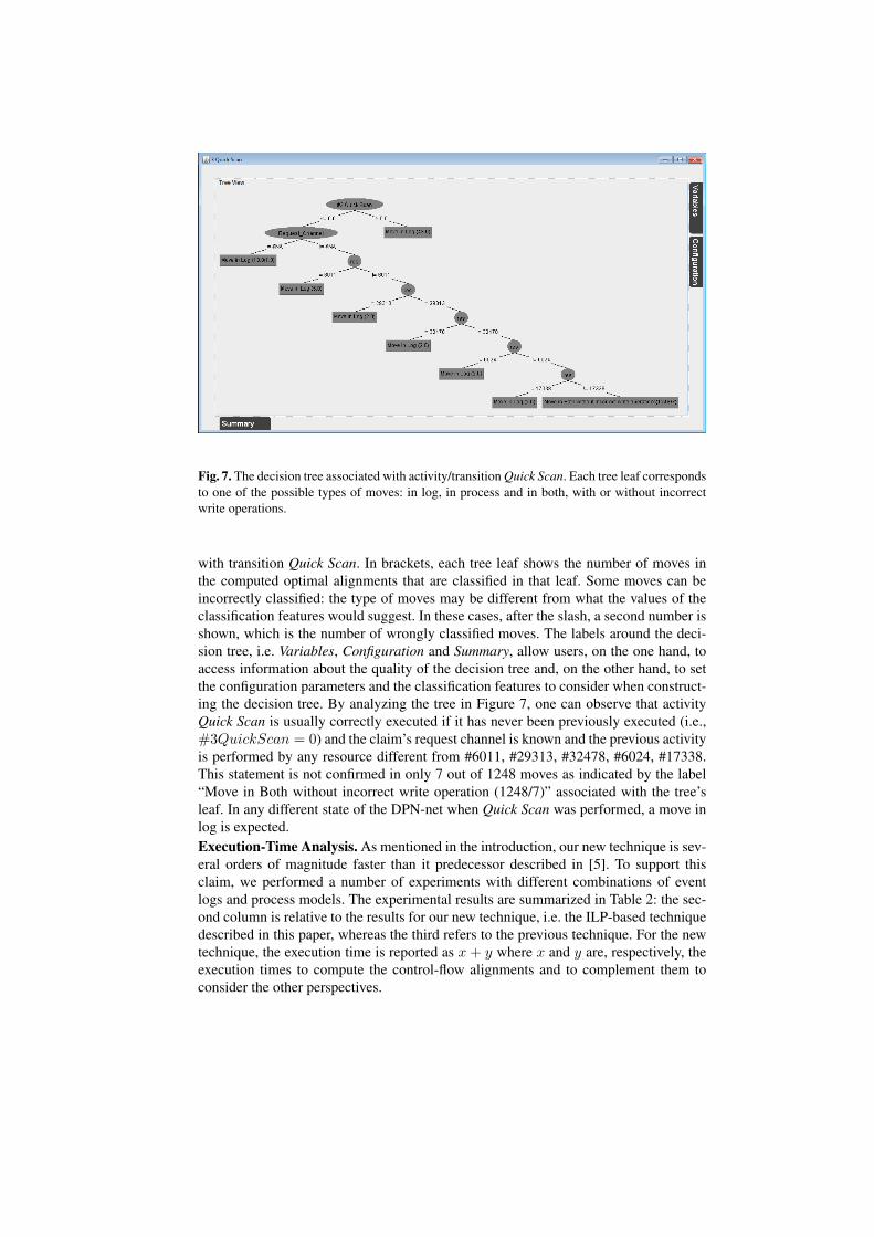
Fig. 7. The decision tree associated with activity/transition Quick Scan. Each tree leaf correspondsto one of the possible types of moves: in log, in process and in both, with or without incorrectwrite operations.
with transition Quick Scan. In brackets, each tree leaf shows the number of moves inthe computed optimal alignments that are classified in that leaf. Some moves can beincorrectly classified: the type of moves may be different from what the values of theclassification features would suggest. In these cases, after the slash, a second number isshown, which is the number of wrongly classified moves. The labels around the deci-sion tree, i.e. Variables, Configuration and Summary, allow users, on the one hand, toaccess information about the quality of the decision tree and, on the other hand, to setthe configuration parameters and the classification features to consider when construct-ing the decision tree. By analyzing the tree in Figure 7, one can observe that activityQuick Scan is usually correctly executed if it has never been previously executed (i.e.,#3QuickScan = 0) and the claim’s request channel is known and the previous activityis performed by any resource different from #6011, #29313, #32478, #6024, #17338.This statement is not confirmed in only 7 out of 1248 moves as indicated by the label“Move in Both without incorrect write operation (1248/7)” associated with the tree’sleaf. In any different state of the DPN-net when Quick Scan was performed, a move inlog is expected.Execution-Time Analysis. As mentioned in the introduction, our new technique is sev-eral orders of magnitude faster than it predecessor described in [5]. To support thisclaim, we performed a number of experiments with different combinations of eventlogs and process models. The experimental results are summarized in Table 2: the sec-ond column is relative to the results for our new technique, i.e. the ILP-based techniquedescribed in this paper, whereas the third refers to the previous technique. For the newtechnique, the execution time is reported as x + y where x and y are, respectively, theexecution times to compute the control-flow alignments and to complement them toconsider the other perspectives.

Event Log & Model The ILP-based technique The Technique in [5]Dutch Insurance Institute 3+7.02 > 2 hsSynthetic Log (n = 4) 0.17+0.38 13.3Synthetic Log (n = 5) 0.2+0.21 48Synthetic Log (n = 6) 0.2+0.44 205
Table 2. Execution time comparison between the ILP-based technique proposed in this paperand the technique in [5] for some log-model combinations. When unspecified, the time units areseconds.
Fig. 8. Scalability of the approach with event logs of different sizes.
The first row is relative to the real-life event log of the Dutch insurance instituteused before to showcase the implementation. Along with the real-life event log, wehave employed the same process models that were used for execution-time analysisreported in Section 5 of paper [5]. In particular, a process model has been consideredwith n parallel activities. Each of n parallel activities performs a write operation for adifferent integer variable, which can be assigned a value between 0 and 42. After the nactivities, a different activity is performed which is associated with a guard involving then variables. Further details on the model are given in [5]. To perform the comparison,we have conducted experiments for n = 4, 5 or 6. For each of these three values, wehave generated an event log that contained 60 traces with data-related deviations onthe write operations. Finally, we have employed both of techniques and compared theexecution time to find the 60 optimal alignments. Comparing the results reported inTable 2, the improvements of the new ILP-based technique are evident.
As further evaluation, we performed detailed experiments to see how the approachscales up with logs of different sizes. To this purpose, we generated 7 events logs bysimulating the model in Figure 2 with CPNTools11. Each event log contained a differentnumber of events while the number of traces were always 3000 (i.e., the average lengthof traces was different in each of 7 event logs). To generate event logs of differentsizes, we instructed the simulation in a way that, on average, each loan request required
11 http://cpntools.org/

a different number of renegotiations (i.e., the loop was executed a large number oftimes in each trace). After the generation of the logs, 20% of events were moved to adifferent position in the respective trace to introduce deviations. Figure 8 shows the theexecution time required to compute the optimal alignments for the traces in the 7 eventlogs. The dotted line indicates the general trend. This shows that optimal alignmentscan be computed efficiently (at least, for the considered example): the execution timegrows almost linearly with event logs of increasing sizes.
7 Conclusion
Various conformance checking techniques have been proposed in recent years. As men-tioned in Section 1, they only focus on the control-flow thereby ignoring, e.g., incorrectrouting decisions, incorrect values assigned to variables, delayed activities, and unqual-ified resources executing activities.
This paper presents a technique that consider data, resources and time when check-ing for process conformance. The proposed technique using state-of-the-art techniquesto first create control-flow alignments. Such alignments are extended to incorporatethe other perspectives. To extend alignments with other perspectives, an additional ILPproblem is constructed and solved for each log trace. The conformance-checking tech-nique discussed in this paper has been implemented in ProM and was tested with varioussynthetic log-model combinations and, also, using a real-life case study. This way wewere able to demonstrate the practical relevance and feasibility of the technique.
Our approach goes much further than existing techniques for data-aware behav-ioral compliance checking [10, 11]. The setting considered in [10, 11] is different fromours: a set of compliance rules rather than a multi-set of log traces is checked. Therealso exist efficient algorithms to perform sequence alignments (e.g., the algorithms ofNeedleman-Wunsch and Smith-Waterman). Similarly, in Process Mining, J.C. Bose etal. [12] have proposed techniques to efficiently align pairs of log traces. Unfortunately,they cannot be applied to find an alignment between a log trace and a process model.In our setting, we do not know a priori the process trace to align with the log trace;conversely, the process trace needs to be chosen, thus minimizing the severity of thedeviations. Moreover, sequence and trace alignments only focus on the activity names,i.e. the control-flow perspective, ignoring the other perspectives.
As future work we would like to relax some of the assumptions currently made inour implementation. The alignments that are returned are optimal under the assumptionthat the control-flow deviations are more severe than those relative to the other perspec-tives. This assumption can be removed if an appropriate number of different control-flow alignments are generated with increasing costs. In fact, this can be formulated asa hill-climbing problem, which can be solved through simulated-annealing techniques.A second assumption is concerned with the guards that need to be conjunctions ofdisjunctions of linear formulas. In general, according to our practical experience, thisassumption is not very limiting. Nonetheless, we aim to operationalize techniques toapproximate non-linear constraints with linear ones.
Currently, we return one optimal alignment for each trace in the event log, but theremay be several additional optimal alignments. An interesting research direction is to de-velop techniques based on finite abstractions to be able to return a compact specificationfor all optimal alignments.

Last but not least, this paper only focuses on computing the fitness dimension ofconformance, whereas the other dimensions are also important indicators of the qualityof a process model, namely precision, generalization and simplicity [1]. Therefore, wealso plan to propose approaches to measure such indicators.
References
1. van der Aalst, W.M.P.: Process Mining - Discovery, Conformance and Enhancement ofBusiness Processes. Springer (2011)
2. Rozinat, A., van der Aalst, W.M.P.: Conformance Checking of Processes Based on Monitor-ing Real Behavior. Information Systems 33 (March 2008) 64–95
3. Weidlich, M., Polyvyanyy, A., Desai, N., Mendling, J.: Process Compliance Measurementbased on Behavioural Profiles. In: Proceedings of the 22nd International Conference onAdvanced Information Systems Engineering. CAiSE’10, Springer-Verlag (2010) 499–514
4. Cook, J., Wolf, A.: Software Process Validation: Quantitatively Measuring the Correspon-dence of a Process to a Model. ACM Transactions on Software Engineering and Methodol-ogy (TOSEM) 8 (April 1999) 147–176
5. de Leoni, M., van der Aalst, W.M.P., van Dongen, B.F.: Data- and Resource-Aware Con-formance Checking of Business Processes. In: 15th International Conference on BusinessInformation Systems. Volume 117 of LNBIP., Springer Verlag (2012) 48–59
6. Verbeek, H.M.W., Buijs, J.C.A.M., van Dongen, B.F., van der Aalst, W.M.P.: XES, XESame,and ProM 6. In: Proceedings of Information Systems Evolution (CAiSE Forum 2010). Vol-ume 72 of Lecture Notes in Business Information Processing. (2011) 60–75
7. Sidorova, N., Stahl, C., Trcka, N.: Soundness Verification for Conceptual Workflow NetsWith Data: Early Detection of Errors With the Most Precision Possible. Information Systems36(7) (2011) 1026–1043
8. de Leoni, M., van der Aalst, W.M.P.: Data-Aware Process Mining: Discovering Decisions inProcesses Using Alignments. In: Proc. of the 28th ACM symposium on Applied Computing(SAC’13), ACM (2013)
9. Adriansyah, A., van Dongen, B.F., van der Aalst, W.M.: Conformance Checking Using Cost-Based Fitness Analysis. In: IEEE International Enterprise Distributed Object ComputingConference, IEEE Computer Society (2011) 55–64
10. Ly, L., Rinderle-Ma, S., Knuplesch, D., Dadam, P.: Monitoring business process complianceusing compliance rule graphs. In: Proceedings of OnTheMove Federated Conferences &Workshops: OTM 2011. Volume 7044 of LNCS. Springer (2011) 82–99
11. Belardinelli, F., Lomuscio, A., Patrizi, F.: Verification of GSM-Based Artifact-Centric Sys-tems through Finite Abstraction. In: Proceedings of the 10th International Conference onService-Oriented Computing (ICSOC’12). Volume 7636 of LNCS. Springer (2012) 17–31
12. Jagadeesh Chandra Bose, R.P., van der Aalst, W.M.P.: Process Diagnostics Using TraceAlignment: Opportunities, Issues, and Challenges. Information Systems 37(2) (2012)