all underground distribution designs are to be a … · conductor for telco bonding from the ground...
TRANSCRIPT

TRENCHING UNDERGROUND DISTRIBUTION
ALL UNDERGROUND DISTRIBUTION DESIGNS ARE TO BE A CUSTOMER PROVIDED TOTAL CONDUIT SYSTEM INSTALLATION.
Clear & 1•12" Min ... l Drivable Area Note 2 Note 2
18" Min.
111§1111 1111
1111 1111 1111
---- Compacted Backfill
.r--1,--- TEP Primary & Secondary Conduit
Note 2
1111 1111 1111
Compacted Backfill ----1---1~
12" Min .
TEP Primary & -+---,,.
Secondary Conduit
Clear & Drivable Area
1111~111= 1111
N ,....,
TEP Only *18" Min. TEP with Other Utilities
NOTES:
Com acted Backfill
*Service Trench with Other Utilities
Service Trench with Communication cable
TEP Service Conduit
1. See SR-207 for bedding and backfill requirements.
611 Min.
liiTI E e Q) •Note 6 ..... 'O
. ro C L. ·- (!) ::E -= :g \0 ·M U.
NOTE: TEP designs exclusively with a customer provided and installed total conduit system.
Secondary and/ or Service Trench
2. Where possible, the trench spoil shall be placed to the opposite side of the access to the trench. Adequate protection shall be provided to protect employees from loose rock or soil that could pose a hazard by falling or rolling into the excavation. Protection can be provided by placing and keeping such materials at least 2 feet from the edge of the excavation, or by other means that provide equivalent protection. This 2 ft. area shall be level and free of debris to permit safe footing during inspection.
3. On-site inspections by TEP are required for open trench, bedding, and shading. Call 918-8300 to schedule inspections.
4. A 2 ft. x 5 ft. bell hole must be provided when modifying an existing CIC installation. Bell holes for service trenches must comply with the requirements of SR-312 and SR-210 where applicable.
5. The minimum horizontal radius in a trench prepared for installation of wave rib conduit system shall be 4 ft., and 12'.6" on a schedule 40 PVC continuous conduit system.
6. Service trenches for the continuous conduit system must be 36 inches in depth.
7. Under no circumstances is a trench to be dug closer than 3 ft. to a down guy anchor rod.
8. See SR-210 for sleeve installation where a trench can not remain open.
9. The service conduit shall be installed into the equipment sites at the same time when the primary and/or secondary conduits are installed. All conduits are to be tied up per the equipment detail, and prior to calling for the trench and conduit inspection.
10. Do Not trench under TEP/UES underground equipment without the presence of an Access Crew. For conduit installation into existing underground equipment, contact Access at 918-8300 (761-7952 UES) to assist with the conduit placement.
.......-....._ INITIATED BY DS REVISION NO. 17 UniSouroeEnergy 1------+------1 EsR coMM. 1-11
SERVIES i-------------1....-------1 SMTACRUZCDUNTY ESR COMM. 6-78 EFFECTIVE DATE 1-17 Tucson Electric Power
SR-209 Pg. 1 of 9
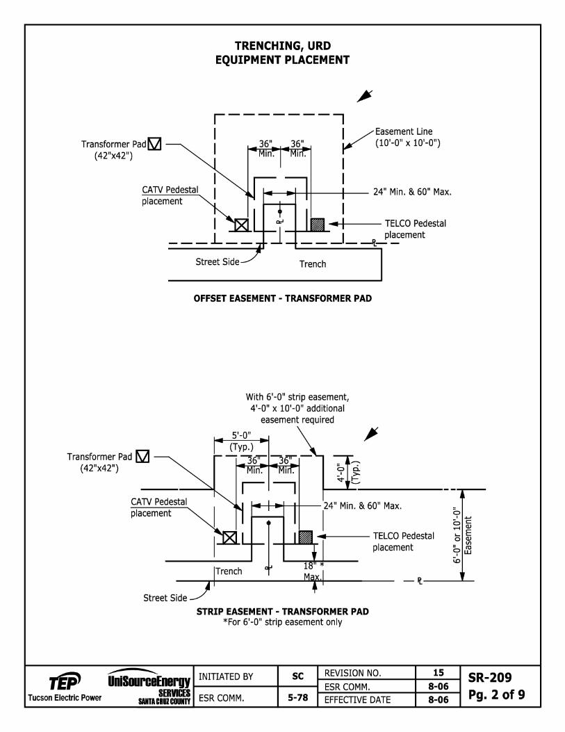
Transformer Pad~ (42"x42")
CATV Pedestal placement
TRENCHING, URD EQUIPMENT PLACEMENT
I ... I TELCO Pedestal
__ _J _ ---Jt_Placement
Street Side Trench
Transformer Pad ~ (42"x42")
placement
OFFSET EASEMENT - TRANSFORMER PAD
With 6'-0" strip easement, 4'-0" x 10'-0" additional
easement required
5'-0"
placement
0 I .....
- C 0 Q)
~E 0 Q)
= :a 9w ~
Street Side ~ -'l.-----'--
Tucson Electric Power
STRIP EASEMENT - TRANSFORMER PAD *For 6'-0" strip easement only
........--._ INITIATED BY SC REVISION NO. 15 UniS•roeEnergy a--------+-----11--------+------1 SERVl:ES 1--ES_R_C_O_M_M_. ______ +-_8_-o_& ....... SMTACRUZCOUNTY ESR COMM. 5-78 EFFECTIVE DATE 8-06
SR-209 Pg. 2 of 9

Tucson Electric Power
TRENCHING, URD EQUIPMENT PLACEMENT
Pedestal D __..(36"x36") Easement Line
-+-, /(10'-0" X 10'-0") ....
s·-~ .. r
Street Side Trench
OFFSET EASEMENT - PEDESTAL
Pedestal D __.. (36"x36") l Easement Line
:• I .J--1.--------------------~~~~ 1 30" TELCO Pedestal
:;::,. ..c Q) u ~ C
0~
placement
------ Trench ____ J \_ JTax. __ 'l: Street Side
STRIP EASEMENT - PEDESTAL * For 6'-0" strip easement only
0 I .....
- C 0 Q)
:: E 0 Q)
= l8 9w \0
.......-...._ REVISION NO. 13 UniSouroeEnergy ..... I_N_IT_IA_TE_o_s_v_-+-_s_c----1....._ _____ +-------1 SERVIES ESR COMM. 8-06
SMTACRUZCDUNTY ESR COMM. 5-78 EFFECTIVE DATE 8-06
SR-209 Pg. 3 of 9

Tucson Electric Power
TRENCHING URD EQUIPMENT PLACEMENT
Sec. Junction Box [QI > (28"x41") 5'-0" Easement Line __ __ (10'-0" X 10'-0") ....
30"Min. r I
14" I TELCO Pedestal 1 placement
-,+-~-rt,i-fB-f--i:=114 .....___1--_ Center Of
L Conduit Tie Up
-- 'l.-
Trench
OFFSET EASEMENT OPTIONAL SECONDARY JUNCTION BOX
5'-0" (typ
With 6'-0" strip easement, 4'-0" x 10'-0" additional
easement required
Sec. Junction Box [QI lo~ 1-' ~ (28"x41") v..__.. L --
TELCO Pedestal placement
~ .~ co .~ -r Center Of
a I .....
- C 0 Q)
~E 0 Q)
= :a 9w ~ (V') E """ E t Conduit Tie Up
----- Trench _ _ ___ Mllax.:_'l: --~
Street Side STRIP EASEMENT
OPTIONAL SECONDARY JUNCTION BOX * For 6'-0" strip easement only
,......-....._ REVISION NO. 13 UniSouroaEnargy .... I_NI_n_AT_E_D _Bv_---+-_sc----11-------+-------1 SERRES ESR COMM. 8-06
SMTACRUZCOUNTY ESR COMM. 5-78 EFFECTIVE DATE 8-06
SR-209 Pg. 4 of 9

Tucson Electric Power
= C: N ·-.:t ~
TRENCHING,URD EQUIPMENT PLACEMENT
Trench
OFFSET EASEMENT J - 1 CABINET
5' (Typ.)
J - 1 Cabinet Iii ( 24"x15" )
With 6'-0" strip easement, 4'-0" x 10'-0" additional
reasement required
CATV Pedestal
TELCO Pedestal
= C: "' ·-.:t~
{placement
-r--~.....,j.---li:----fa--::t--,,,,.,... Center Of
TRENCH
Cable Tie Up
*18" Max.
STRIP EASEMENT J - 1 CABINET
* For 6'-0" strip easement only
0 I .....
- C: 0 a.,
~E 0 a.,
= :8 9w \0
---..... INITIATED BY SC REVISION NO. 4 UniSouroeEnergy 1------+---_:--------+-----1 SERVl:ES ESR COMM . 8-06
SUTACRUZCOUNTY ESR COMM . 10-91 EFFECTIVE DATE 8-06
SR-209 Pg. 5 of 9

Profile View
Duct Plug
2 1/2" X 36" X goo Schedule 40 / Electrical PVC sweep
Secondary Connectors
Duct Plug 0
Front View
Tucson Electric Power
I
CONDUIT PLACEMENT EXISTING SINGLE PHASE
STEEL PEDESTAL
Install the pull rope for the entire service run
.> Final Grade Refer to SR-218 for all service stubs
Pedestal Stake
Pedestal
Final Grade
Conduit Schedule 40 Electric PVC
42"
2 1/2" x 5'-0" Schedule 40 Electrical PVC stub
Top View
Pedestal {Stake
2 1/2 " x 36" x goo and 5'-0" stub Front
INITIATED BY GC REVISION NO. ESR COMM.
ESR COMM. 8-06 EFFECTIVE DATE
17 7-12 8-12
SR-209 Pg. 6 of 9

Service Conduits 2 1/2" / 4" for 1 to 2 lot applications.
4" conduit systems require the installation of Smooth - Cor conduit system.
CONDUIT PLACEMENT TIE UP PRIMARY /SERVICE URD
42"
Center of Equipment
0 The customer to provide the tie-up support & ground wire for total conduit installation
Pad Mounted Transformer Plan View
Schedule 40 PVC 3'-0" x goo & a 5'-0" straight stick is preferred for the service stub out. The stub out is to be in place for ~r~und the primary trench conduit inspection.\ 0l Ground Rod 6" ... Above Final Grade. "f('
"!I' Final Grade
111§1111 1111
If using Wave-Rib conduit, leave 4 to 5 extra feet to assist with shaping and holding the conduit in place. Trim the conduit after the transformer backfill inspection has passed.
If installing conduit into an existing transformer, a schedule 40 2 1/2" x 36" x 90° will be required. Call for an access appointment at 918-8300.
Service Conduits Prima Conduits
Note: Ground Rods are Not Permitted to be cut under any circumstance. If soil conditions prohibit driving the ground rod per the SR, contact TEP's design department.
Pad Mounted Transformer Front View
---...... REVISION NO. 10 UniSouroeEnergy 1-I_N_IT_IA_TE_o_s_v_--1,-_M_s----1 ESR coMM. 3-16
Tucson Electric Power SERVl:ES L-.::~::.::.:..:.:..:.:...-----1~;....;;;.;;,......i
SIIJACRUZCOlm ESR COMM. 10-88 EFFECTIVE DATE 4-16
SR-209 Pg. 7 of 9

I I
NOTES:
TRENCHING, URD EQUIPMENT PLACEMENT FOR CONDUIT INSTALLATION
1. EASEMENT/ EQUIPMENT IDENTIFICATION Customer is to provide property pins and/ or swing ties (stakes) to the center of equipment at the UG equipment (Transformer, Pedestal, J-10, J-1, J-2, etc.) location. These pins/ stakes will be in place for the trench/ conduit inspection and backfill/ mandrel inspection.
2. CONDUIT PLACEMENT / TRANSFORMER PAD SITE PREPARATION
A) Pad and trench sites shall be level and at final grade before calling TEP for a trench/ duct inspection. Driven ground rod to be 6 inches above final grade.
B) Customer to utilize the approved TEP conduit template (purchased through TEP) during the backfill process to ensure proper conduit and ground rod placement final grade. Duct plugs are required for all conduits (no duct tape).
C) After the conduits (SR-205) and ground rods are in place, the customer is to install a #6 solid soft drawn copper conductor for Telco bonding from the ground rod 2 ft. above the pad (at the ground rod), 12 inches away from the front of the pad and 36 inches to the right of the pad site. Bury the conductor 12 inches below final grade and coil up approximately 2 ft. of conductor. With the template in place, pour concrete on the conduit (see SR-205 & 215, Pg. 1 of 2) if using PVC and call for an inspection. After passing the inspection, backfill and compact (95%), level the equipment site and install the transformer pad. The conduit shall be cut 1 inch above the top of the pad and covered with the appropriate duct plug. See SR-208 for equipment site preparations, including sites with slopes.
D) The customer to call for a transformer pad site, pedestal site, and mandrel inspection, upon approval the customer will pour a slurry of concrete (1/2 inch thick) inside the entire opening for rodent protection.
3. PEDESTAL SITES TEP to provide the pedestal. The customer is to excavate and install per SR-209 page 9. After the conduits (SR-205) are in place, the customer is to install a #6 solid soft drawn copper conductor for Telco bonding from 2 ft. above the sub grade (next to the right side of the conduits), 12 inches away from the front of the pedestal and 24 inches to the right of the equipment site. Bury the conductor 12 inches below final grade and coil up approximately 2 ft. of conductor.
4. J-1 CABINET SITES
TEP to provide the subsurface base. The customer is to excavate and install per SR-235. Install ground wire per note 3 on this page.
S. J-2 CABINET SITES TEP to provide the subsurface base. The customer is to excavate and install per SR-234.
6. SECONDARY JUNCTION BOX SITES (J-10) - CUSTOMER OPTION (in place of pedestals)
The customer to provide and install the 20K rated J-10 box per SR-209 page 9. Install ground wire per note 3 on this page.
A) After the conduit (SR-205) is installed, the customer to provide, install and level an approved TEP secondary junction box (see below) so the top of the box is 1 inch above final grade. Place the lid on the box.
B) Approved secondary junction box (17"x30"): Armorcast Products Co. - Cat. No. 6001640-AS CDR Systems - Cat. No. PA30-1730-18S Christy Concrete Products - Cat. No. FL36BOX18 Electrimold Inc. - Cat. No. ECAA-173018-100 New Basis - Cat. No. FMA173018TN20001P212NOOOOO Quazite - PT1730BA (Box), PT1730CAOO (Cover)
TEP will furnish the transformer pads, pedestals, and ground rods to the job site at the customers' request. Please give TEP a 2 week notice and specify a contact name, phone number and the material staging area. It's the customers' responsibility for the care of this material. The customer must sign for the delivered material. Any lost, or damaged material will be the responsibility of the customer to replace with approved TEP material.
Note: Ground Rods are Not Permitted to be cut under any circumstance. If soil conditions prohibit driving the ground rod per the SR, contact TEP's design department. ......_
.......-....._ INITIATED BY GC REVISION NO. 5 UniS•roaEnargy 1------+---_:--------+------1 Tucson Electric Power
SERVl:ES ESR COMM. 3-16 SMTACRUZCDUNTY ESR COMM. 6-05 EFFECTIVE DATE 4-16
SR-209 Pg. 8 of 9
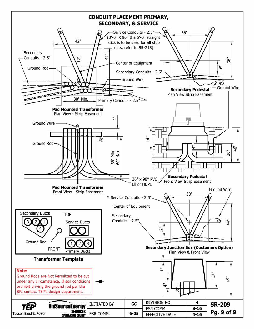
CONDUIT PLACEMENT PRIMARY, SECONDARY, & SERVICE
Secondary Conduits - 2.5"
Ground Rod
Pad Mounted Transformer
Service Conduits - 2.5" (3'-0" X goo & a 5'-0" straight stick is to be used for all stub
outs, refer to SR-218)
Center of Equipment
Secondary Conduits - 2.5"
--Ground Wire
Secondary Pedestal L. Ground Wire Plan View Strip Easement
Plan View - Stlip Easement :... j Ground Wire-.......__
Ground Rod
C: X ·- rtl ::E ::E ~= M~
---------1:!!!!!::::::_-l-__:::::::::::1-===~~:-- 36" x goo PVC
Pad Mounted Transformer Front View - Strip Easement
Ell or HOPE
Secondary Pedestal Front View Strip Easement
Ground Wire 30"
* Service Conduits - 2.5" ~
Center of Equipment
TOP
Service Ducts
Transformer Template
Note: Ground Rods are Not Permitted to be cut under any circumstance. If soil conditions .._ prohibit driving the ground rod per the SR, contact TEP's design department.
__.......-..... UniS•roeEnergy .... I_NI_n_AT_E_o _sv_--+------1 GC
Tucson Electric Power SERVl:ES SUTICRUZCOUNTY ESR COMM. 6-05
Secondary Junction Box (Customers Option) ~n View & Front View
~
T REVISION NO. 4 SR-209 ESR COMM. 3-16
Pg. 9 of 9 EFFECTIVE DATE 4-16