all-vinyl window mull, stack, or mull & stack instructions
TRANSCRIPT

All-Vinyl Window Mull, Stack, or Mull & Stack Instructions
Units with Integral Brickmould and J-Channel
IMPORTANT: Please read before you begin.
HEAD DRIP CAP
SILL DRIP CAP
EXTERIOR MULL POST
INTERIOR MULL CLIP
HEAD JOINING PLATEPLUMB PLATE
SILL JOINING PLATE
EXTERIOR MULL POST
INTERIOR MULL CLIP
STACK DRIP CAP
JOINING PLATE
PLUMB PLATE
Part No.1239342 Install 288 5/09 © 2009 Shield Family Brands
MULLING
STACKING
Units viewed from the exterior.
Units viewed from the exterior.

1
ALL-VINYL WINDOW – MULL, STACK OR MULL & STACK
TABLE OF CONTENTSSTART PAGE
About Mulling, Stacking & Mulling and Stacking . . . . . . . . . . . . . . . . . . . . . . . . . . . . 2
Safety Precautions . . . . . . . . . . . . . . . . . . . . . . . . . . . . . . . . . . . . . . . . . . . . . . . . . . . . . 3
General Information . . . . . . . . . . . . . . . . . . . . . . . . . . . . . . . . . . . . . . . . . . . . . . . . . . . . 4
Mull and Stack Components . . . . . . . . . . . . . . . . . . . . . . . . . . . . . . . . . . . . . . . . . . . . . 5
Unit Preparation . . . . . . . . . . . . . . . . . . . . . . . . . . . . . . . . . . . . . . . . . . . . . . . . . . . . . . . 6
Tin Snips, Locking Pliers, Utility Knife
Mull Clip and Mull Post Configuration . . . . . . . . . . . . . . . . . . . . . . . . . . . . . . . . . . . . . 7
Measuring for Mull Clips and Mull Posts . . . . . . . . . . . . . . . . . . . . . . . . . . . . . . . . . . . 8
Tape Measure, Pencil, Paper to Record Measurements, Hack Saw, Utility Knife
Mull Clip Installation – Interior . . . . . . . . . . . . . . . . . . . . . . . . . . . . . . . . . . . . . . . . . . . 9
High Quality Clear Exterior Silicone Sealant, Caulking Gun, Utility Knife, End Nipper
Pliers, Wood Block, Clean Soft Rags, Denatured Alcohol, Spray Bottle, Soft-Faced
Hammer, Mull Clips, 1/2" Diameter Foam Caulk Saver/Backer Rod
Mull Post Installation – Exterior . . . . . . . . . . . . . . . . . . . . . . . . . . . . . . . . . . . . . . . . . 10
High Quality Clear Exterior Silicone Sealant, Caulking Gun, Utility Knife, End Nipper
Pliers, Wood Block, Clean Soft Rags, Denatured Alcohol, Spray Bottle, Soft-Faced
Hammer, Mull Posts, 1/2" Diameter Foam Caulk Saver/Backer Rod
Apply Joining Plates; Install Plumb Plates – Optional Procedure . . . . . . . . . . . . 14
Joining Plates, #8 x 1/2" Phillips Pan Head Stainless Steel Sheet Metal Screws,
Power Drill with Screwdriver Bits
Install Head Drip Cap . . . . . . . . . . . . . . . . . . . . . . . . . . . . . . . . . . . . . . . . . . . . . . . . . . 15
Matching Drip Cap, Silicone Sealant, Caulking Gun, Measuring Tape, Pencil, End
Nipper Pliers, Utility Knife, Sill Gaskets, Foam Backer Rod
Seal Side and Sill Joints . . . . . . . . . . . . . . . . . . . . . . . . . . . . . . . . . . . . . . . . . . . . . . . 18
Matching Drip Cap, Silicone Sealant, Caulking Gun, Measuring Tape, End Nipper
Pliers, Utility Knife
Table of Contents and Tool/Material Requirements
Schield Family Brands reserves the right, as necessary, to change product specifications, installation procedures, materials,
prices and terms of purchase without notice. Before installing units check with local building codes for your area for proper compliance.

2
ALL-VINYL WINDOW – MULL, STACK OR MULL & STACK
IMPORTANT: Thoroughly read and follow these instructions. Failure to assemble
as recommended will void any warranty, expressed or implied. Check building codes
for the area in which the windows are being installed before installation to ensure
proper compliance. The instructions that follow are based on typical frame construction.
Specific applications may differ. The window manufacturer recommends that you consult a
qualified installation professional. The window manufacturer is not responsible for installa-
tion.
Some local building codes may require the use of continuous head drip caps over mulled
windows. Full length drip caps are available.
The following instructions are for assembling individual window units into a mulled,
stacked, or mulled and stacked configuration prior to installation. To actually install the
newly combined unit into a rough opening, follow the installation instructions packed with
one of the individual windows.
About Mulling, Stacking & Mulling and Stacking
Stacking, mulling, or combinations of stacking and mulling may have installation
restrictions and require additional reinforcement in your area. The window manu-
facturer recommends that the installer consult a registered Architect or local
Structural Engineer for guidance to ensure the installation meets all codes and rules
regarding installation of mulled, stacked, or mulled and stacked combinations. St
acke
d (S
tack
ing)
Mulled (Mulling)
FIGURE 1The process for mulling or stacking differs from
mulling and stacking.
Please observe the following definitions for terms
used in the subsequent instructions:
•Mulled (Mulling): Joining two or more units
together horizontally (FIGURE 1). Also called
horizontal mulling.
•Stacked (Stacking): Joining two or more units
together vertically (FIGURE 1). Also called verti-
cal mulling.
•Mull and Stack: Joining three or more units
together horizontally and vertically (FIGURE 1).

3
ALL-VINYL WINDOW – MULL, STACK OR MULL & STACK
Please note the following precautions for your safety and well being.
Weight of window and accessories will vary.
Use a reasonable number of people with
sufficient strength to lift, carry and install
window unit(s) and accessories. Always
consider site conditions and use appropriate
techniques when installing.
Falling from window opening may
result in serious injury or death. DO
NOT leave openings unattended when
children are present.
Screen will not stop children,
any one or anything from
falling out window.
Keep children and objects
away from open window.
CUT HAZARD*Non-safety Glass.
*May cause serious
injuries if broken.
*Do not install where
tempered safety glass
is required.
Recognize this symbol. This is the Safety-Alert symbol. When you see this symbol be
alert to the potential for personal injury or product damage.
Improper use of hand and power tools
could result in personal injury and/or
product damage. Follow equipment
manufacturers’ instructions for safe
operation. Always wear safety glasses.
High-quality, exterior, neutral-cure, clear, sil-
icone sealant (compatible with vinyl) is to be
used for all procedures in the following
instructions which call for caulking or
sealant.
IMPORTANT
Safety Precautions

4
ALL-VINYL WINDOW – MULL, STACK OR MULL & STACK
General Information
The following instructions are for complet-
ing a standard mull, stack, or mull and
stack operation for vinyl windows.
These instructions are for windows with
an integral brickmould and J-Channel
(FIGURE 1). Units may come with an
optional J-Channel filler, however, mulling
and stacking procedures are the same.
Contact your customer service representa-
tive for instructions for mull and mull stack
operations on other unit types and config-
urations.
To install a combined unit, follow the
installation instructions packed with the
individual windows. This booklet does not
contain unit installation instructions.
EXTERIOR
NailingFin
NailingFin
J-Channel
OptionalJ-ChannelFiller
J-Channel
IntegralBrickmould Integral
Brickmould
SIDE VIEW – HEAD JAMBFIGURE 1
FIGURE 2
StuccoLip
NailingFin
SIDE VIEW HEAD JAMB
NOTE: If your unit looks like (FIGURE
2) do not use these instructions
for mulling, stacking, or mulling
and stacking. Obtain Install 226,
Part No. 213568.

5
ALL-VINYL WINDOW – MULL, STACK OR MULL & STACK
Mull and Stack Components
Head DripCap With J-Channel
Head DripCap ForCasement &Awning
Head DripCap WithJ-ChannelFiller
Sill and SideDrip Cap WithJ-ChannelFiller
Sill and SideDrip Cap WithJ-Channel
Sill Drip Cap For Single Hung
Mull Clip Mull Post
Mull PostSelf-AdhesiveGasket
Joining & Plumb Plate Caulk Saver/Backer Rod
Install ¼" Deep Into Mull Post
¼"
Components to complete a mull and stack
operation are shown in (FIGURE 1).
Each horizontally mulled unit requires a
full length head drip cap and a partial sill
drip cap.
Stacked units require partial drip caps
applied to the side jambs, where the units
join.
Four-way mull and stack requires a full-
length head drip cap, a partial sill drip cap,
and side caps.
Joining plates are used at mull and stack
joints and are secured to the side jambs
with #8 x 1/2" Phillips pan head stainless
steel screws.
The self-adhesive gaskets are applied to
the back side of the nailing fin to help seal
the gap between adjacent nail fins. They
should be applied to the head, sides and
sill joints as appropriate.
The backer rod is inserted into the end of
the mull post so it is 1/4" below mull post
edges. The 1/4" gap is filled with silicone.FIGURE 1
Sill drip cap applied to a hori-zontal mull joint.
Stack joint showing mull post,caulk backer rod, and joiningplate.
6
ALL-VINYL WINDOW – MULL, STACK OR MULL & STACK
FIGURE 1
SCORE WITHUTILITY KNIFE
xxxxx x
x
x
1B
1A
FIGURE 22A
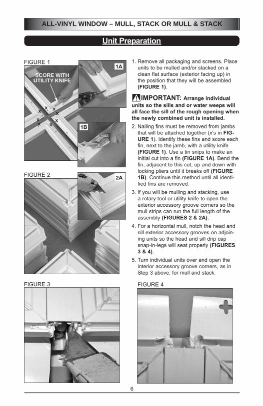
Unit Preparation
1. Remove all packaging and screens. Place
units to be mulled and/or stacked on a
clean flat surface (exterior facing up) in
the position that they will be assembled
(FIGURE 1).
IMPORTANT: Arrange individual
units so the sills and or water weeps will
all face the sill of the rough opening when
the newly combined unit is installed.
2. Nailing fins must be removed from jambs
that will be attached together (x’s in FIG-
URE 1). Identify these fins and score each
fin, next to the jamb, with a utility knife
(FIGURE 1). Use a tin snips to make an
initial cut into a fin (FIGURE 1A). Bend the
fin, adjacent to this cut, up and down with
locking pliers until it breaks off (FIGURE
1B). Continue this method until all identi-
fied fins are removed.
3. If you will be mulling and stacking, use
a rotary tool or utility knife to open the
exterior accessory groove corners so the
mull strips can run the full length of the
assembly (FIGURES 2 & 2A).
4. For a horizontal mull, notch the head and
sill exterior accessory grooves on adjoin-
ing units so the head and sill drip cap
snap-in-legs will seat properly (FIGURES
3 & 4).
5. Turn individual units over and open the
interior accessory groove corners, as in
Step 3 above, for mull and stack.
FIGURE 3 FIGURE 4
4-WAY MULL/STACK COMBINATIONViewed from the exterior
Horizontal Mull PostsMeet at Vertical Post
Vertical Mull PostRuns Full Height
7
ALL-VINYL WINDOW – MULL, STACK OR MULL & STACK
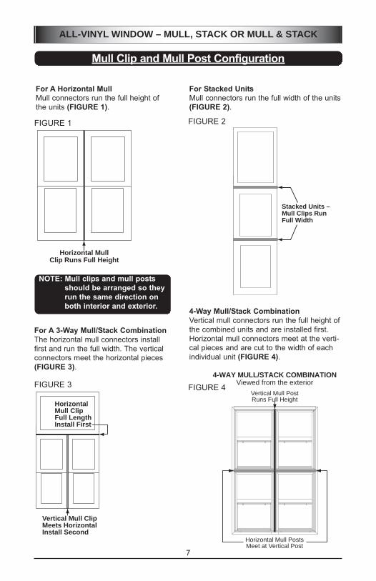
Mull Clip and Mull Post Configuration
4-Way Mull/Stack Combination
Vertical mull connectors run the full height of
the combined units and are installed first.
Horizontal mull connectors meet at the verti-
cal pieces and are cut to the width of each
individual unit (FIGURE 4).
For A Horizontal Mull
Mull connectors run the full height of
the units (FIGURE 1).
For Stacked Units
Mull connectors run the full width of the units
(FIGURE 2).
HorizontalMull ClipFull LengthInstall First
Vertical Mull ClipMeets HorizontalInstall Second
For A 3-Way Mull/Stack Combination
The horizontal mull connectors install
first and run the full width. The vertical
connectors meet the horizontal pieces
(FIGURE 3).
Stacked Units –Mull Clips RunFull Width
FIGURE 1 FIGURE 2
FIGURE 3 FIGURE 4
Horizontal MullClip Runs Full Height
NOTE: Mull clips and mull posts
should be arranged so they
run the same direction on
both interior and exterior.

8
ALL-VINYL WINDOW – MULL, STACK OR MULL & STACK
Measuring for Mull Clips and Mull Posts
Measure acrossexterior accessory
grooves for each stack
Horizontal Mull Pieces
1. Lay units on a clean flat surface, exterior facing up, with the adjacent nail fins removed
as previously instructed, and arranged as they will be installed.
2. Slide units tightly together so they touch.
3. Record all measurements.
4. For a Single Mull or Stack (FIGURES 1 & 2, Page 7) measure across the exterior
accessory grooves see (FIGURES 1 & 2, below).
FIGURE 1
The smaller mull clip (FIGURE 3) is applied
on the interior and the mull post (FIGURE 4)
is installed from the exterior.
Follow the correct procedures as explained
in the following sections.
FIGURE 3 FIGURE 4
Mull Clip Mull Post
FIGURE 2
5. For a 3-Way Mull Stack Combination
(FIGURE 3, Page 7) measure height as
shown in (FIGURE 2, right). For width,
measure across the top unit as in
(FIGURE 1, above).
6. For a 4-Way Mull Stack Combination (FIGURE 4, Page 7) measure height the full
length of the combined units and add 1/2". For width, measure width of each unit,
across the exterior accessory grooves, as in (FIGURE 1, above).
7. Cut the mull clips and mull posts to length.
Measure acrossexterior accessorygrooves for eachhorizontal mull

Mull Clip Installation – Interior
FIGURE 3
FIGURE 1
3A
1. Place units on a clean, flat, protected sur-
face with the interior facing up. Arrange
units as they will be installed. All water
weeps of the combined units must face
toward the sill of the rough opening. Use
1/2" plywood spacer blocks to set units a
uniform 1/2" apart.
IMPORTANT: Use a straight-edge or level to align units so they aresquare, straight, and even with eachother.
2. For a 3 or 4-Way assembly, insert 5" long,
1/2" diameter caulk backer rod into the
gap where the units meet (FIGURE 1).
Push backer rod down so there is at least
1/4" space above the rod. Fill this 1/4"
space with silicone sealant applied over
the backer rod (FIGURE 1).
3. Using a utility knife, rotary tool, or end
nipper pliers, cut the snap-in-legs back
1/2" on each end of the mull clip
(FIGURE 2).
4. Apply a minimum 1/4" continuous bead
of caulk the full length of each mull clip,
along the side of each snap-in-leg before
installing the clip (FIGURE 2).
NOTE: If mulling and stacking, install the
vertical mull clip first. Then install the
horizontal mull clip(s).
5. Be sure units are still aligned with each
other and then start the mull clip into one
end of the accessory groove. With a rub-
ber mallet (FIGURE 3), lightly tap so the
clip snaps into the accessory grooves on
both units (FIGURE 3A). Ensure that the
mull clip has fully snapped into place
along the unit’s entire length. If needed,
use a wood block and rubber mallet to tap
mull clips tightly into place.
6. The shorter mull clips must fit tight against
the longer clips at their intersection (FIG-
URES 3 & 3A).
7. After installing all the interior mull clips,
remove excess caulk with denatured
alcohol dampened clean soft rags.
Cut back"½
Apply caulk besidesnap-in-legs, full length of mull clip.
Cut Back ½"on both ends
FIGURE 2
9
ALL-VINYL WINDOW – MULL, STACK OR MULL & STACK
BACKER ROD
SILICONESEALANTON TOP OFBACKER ROD
10
ALL-VINYL WINDOW – MULL, STACK OR MULL & STACK
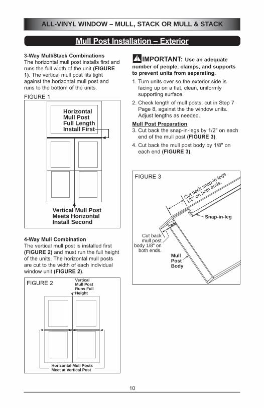
Mull Post Installation – Exterior
IMPORTANT: Use an adequate
number of people, clamps, and supports
to prevent units from separating.
1. Turn units over so the exterior side is
facing up on a flat, clean, uniformly
supporting surface.
2. Check length of mull posts, cut in Step 7
Page 8, against the the window units.
Adjust lengths as needed.
Mull Post Preparation
3. Cut back the snap-in-legs by 1/2" on each
end of the mull post (FIGURE 3).
4. Cut back the mull post body by 1/8" on
each end (FIGURE 3).
3-Way Mull/Stack Combinations
The horizontal mull post installs first and
runs the full width of the unit (FIGURE
1). The vertical mull post fits tight
against the horizontal mull post and
runs to the bottom of the units.
4-Way Mull Combination
The vertical mull post is installed first
(FIGURE 2) and must run the full height
of the units. The horizontal mull posts
are cut to the width of each individual
window unit (FIGURE 2).
HorizontalMull PostFull LengthInstall First
Vertical Mull PostMeets HorizontalInstall Second
FIGURE 1
VerticalMull PostRuns FullHeight
Horizontal Mull PostsMeet at Vertical Post
FIGURE 2
FIGURE 3
Snap-in-leg
Cut back snap-in-legs
1/2" on both ends.
Cut backmull post
body 1/8" onboth ends.
MullPostBody

11
ALL-VINYL WINDOW – MULL, STACK OR MULL & STACK
Mull Post Installation – Exterior (cont.)
For a 1-Way Mull or Stack the mull post runs the full length of the unit(s).
For a 3 or 4-Way Assembly:
The shorter mull posts, that meet the full-length mull post, must have the ends that join
with the full-length post prepared prior to installation. The preparation is necessary to
ensure a weather-tight seal at the joint. The full-length mull post is installed first.5. For the full-length mull post, apply a minimum 1/4" continuous silicone bead the full
length, along the snap-in legs on each side of each mull post before installing (FIGURE
4).
6. Place a caulked mull post between the units and align one end flush with top or bottom
of window frame.
7. Start one end of the mull post into the acces-
sory grooves. Tap along the mull post to seat
the snap-in-legs into both units (FIGURE 5).
Ensure mull posts are fully snapped into place
along the unit’s entire length. If necessary,
use a wood block and rubber mallet to tap
mull posts tightly into place. Repeat for all full-
length mull posts.
AccessoryGrooves
Apply caulk on bothsides of mull post alonginside edge of snap-in-legs.
Place mull strip in between units.Use rubber mallet to seat snap-in-legsinto the accessory grooves.
FIGURE 4
FIGURE 5

Mull Post Installation – Exterior (cont.)
12
ALL-VINYL WINDOW – MULL, STACK OR MULL & STACK
For a 3 or 4-Way Assembly:
8. Insert a 1/2" diameter 2" long caulk backer rod
into the mull post cavity on the end that meets
the full-length mull post (FIGURE 6). Push
backer rod into the mull post so there is at least
1/4" space above the backer rod. Fill this 1/4"
space with silicone sealant (FIGURE 7). Sealant
should overfill the cavity. Apply sealant to snap-
in-legs of mull post and to exterior accessory
grooves (see Step 5 above).
9. Place shorter mull post into the space
between the units, with the prepared
end toward the full-length mull post just
installed (FIGURE 8). Butt the shorter
mull post tightly against the full-length
post and tap the snap-in-legs down into
the exterior accessory grooves. Ensure
mull posts are fully snapped into place.
If necessary, use a wood block and rub-
ber mallet to tap mull posts tightly into
place. Repeat for all short mull posts.
10. Remove excess silicone with clean soft
rags dampened with denatured alcohol.
Mull Post
Caulk Saver/Backer Rod
Install ¼" Deep Into Mull Post
¼"
Mull Post
Fill void above backer
rod with sealant. Allow
excess to form at end
of mull post to help
seal against full length
mull post.
BACKER ROD
VERTICAL MULL POST – FULL LENGTH
HORIZONTALMULL POST–MEETS VERTICAL
SEALANT –FROM BACKERROD TO END OF
HORIZONTAL MULL POST
FIGURE 7
FIGURE 6
FIGURE 8

13
ALL-VINYL WINDOW – MULL, STACK OR MULL & STACK
Mull Post Installation – Exterior (cont.)
Completely fill areaabove backer rodwith silicone sealant.
Fill Gap Between Units
11. There will be a hollow in the mull post at the head, and sill on mulled units and at side
jambs on stacked units (FIGURES 9 & 9A).
12. Push a foam backer rod into each mull post hollow leaving 1/4" space above the
backer rod (FIGURES 9A & 10).
13. Completely fill area above the backer rod with silicone (FIGURE 11).
AddCaulkSaver
AddCaulkSaver
AddCaulkSaver
AddCaulkSaver
FIGURE 9 FIGURE 9A
Install backer rodinto mull post soit is recessedat least 1/4"
FIGURE 10 FIGURE 11
14. After sealant application, attach a self-adhesive gasket to the interior side of the nail-
ing fin and frame to cover the mull gap (FIGURES 12 & 13).
FIGURE 12 FIGURE 13

14
ALL-VINYL WINDOW – MULL, STACK OR MULL & STACK
Apply Joining Plates
Install Plumb Plates – Optional Procedure
JOININGPLATE
#8 X ½"SCREWS(typ)
BACKERROD
SEALANT
MULLPOST
FIGURE 11. Use a level or straightedge to check that
units are still aligned with each other.
They must be square, even, and straight.
Make necessary adjustments.
2. After mull clips & mull posts are installed,
caulked, and gaskets applied, install a
joining plate over each stacked and/or
mulled joint (FIGURE 1). Apply a joining
plate at the head, sill, and sides based on
mull type.
NOTE: Be sure backer rod, caulk, and gas-
kets are applied before installing
joining plates.
3. Align plate so it straddles the joint and
attach with at least eight screws, four on
each side of mull or stack joint. Use #8 x
1/2" Phillips, pan head stainless steel
sheet metal screws (FIGURE 1).
To help plumb the window while installing,
attach additional joining plates on each side
of each mull (top and bottom) or stack joint
(both sides) (FIGURES 1 & 2).
These plates will help you attain a more
accurate alignment of the units with the
rough opening.
After the window is installed the plates are
bent at a right angle and fastened to the
framing members.
FIGURE 1
FIGURE 2
Mull Joint Viewed
From Above
Stack Joint Viewed
From the Side

15
ALL-VINYL WINDOW – MULL, STACK OR MULL & STACK
Install Head Drip Cap
IMPORTANT: Head drip cap runs full width of mulled unit(s).
NOTE: There is a separate drip cap for J-Channel windows and those with the optional
J-Channel filler. Be sure your drip cap is the proper type (FIGURE 1).
EXTERIOR
NailingFin
OptionalJ-ChannelFiller
IntegralBrickmould
SIDE VIEW – HEAD JAMBwith Drip Caps
FIGURE 1
FIGURE 2
FIGURE 3
1. Measure overall width of mulled assembly across outside edges of integral brickmould.
2. Cut a vinyl drip cap to this length.
IMPORTANT: Be sure accessory grooves at mull joint are opened. See Page6 Step 4.3. Trim excess weld build-up at the frame corners on the top of the units.
4. Caulk mull joints at the top of each window frame (FIGURE 2). Caulk top of window
frames for full length of mulled assembly and at each end of head jamb (FIGURE 3).

16
ALL-VINYL WINDOW – MULL, STACK OR MULL & STACK
Install Head Drip Cap (cont.)
5. Center drip cap on the width of the com-
bined unit and place the edge of the snap-
in-leg into the exterior accessory groove
(FIGURE 4).
6. Work along width of unit, pulling drip cap
up and over nailing fin (FIGURE 5) while
firmly pushing the drip cap down into the
J-Channel pocket (FIGURE 6). Ensure
snap-in-leg fully seats in exterior accesso-
ry groove along drip cap’s full length.
FIGURE 4
FIGURE 5
FIGURE 6

17
ALL-VINYL WINDOW – MULL, STACK OR MULL & STACK
Install Head Drip Cap (cont.)
Cut inward, onthese seams,until flush withthe bottom of the J-Channel.Fold flap down
into J-Channel
Drip CapFolded Edge
NailingFin
7. Cut the drip cap, only the part extending beyond the head J-Channel pocket, inward
along its seams as shown in (FIGURE 7) and fold the resulting flap down into the
J-Channel pocket. This allows for siding to be placed into the J-Channel.
8. Use a shop towel dampened with denatured alcohol to clean-off excess caulk.
IMPORTANT: Allow the caulk to set up before handling, moving, or installing
the assembled unit.
FIGURE 7

18
ALL-VINYL WINDOW – MULL, STACK OR MULL & STACK
Seal Side and Sill Joints
1. Cut a 6" long piece of drip cap for the sill and/or sides. See Page 5 to select the right
shaped drip cap. Notch snap-in leg at center of drip cap to provide clearance for the
mull post or mull clip (FIGURE 1).
2. Caulk the exterior as shown below in (FIGURE 2). Caulk the sill joint on a mulled unit
and the sides on a stacked unit.
3. Install drip caps as appropriate for your assembly.
FIGURE 2 – ONE SIDE OF A
STACKED UNIT
FIGURE 2 – ONE SIDE OF A STACKED
UNIT COMPLETED.
SILL WOULD BE SIMILAR
Mull or mull and stack assembly is now complete.
Allow caulk to set up before installing window.
To install the “new” mulled or stacked unit, follow installation instructions packed with one
of the individual windows.
NOTCH
MULLPOST
DRIP CAP
FIGURE 1

19
ALL-VINYL WINDOW – MULL, STACK OR MULL & STACK
Notes