all‑climate aluminum‑ion batteries based on binder‑free
TRANSCRIPT
Vol.:(0123456789)
1 3
All‑Climate Aluminum‑Ion Batteries Based on Binder‑Free MOF‑Derived FeS2@C/CNT Cathode
Yuxiang Hu1, Hongjiao Huang2, Deshuang Yu2, Xinyi Wang1, Linlin Li2, Han Hu3, Xiaobo Zhu1, Shengjie Peng2 *, Lianzhou Wang1 *
ISSN 2311-6706e-ISSN 2150-5551
CN 31-2103/TB
ARTICLE
Cite asNano-Micro Lett. (2021) 13:159
Received: 21 April 2021 Accepted: 18 June 2021 © The Author(s) 2021
https://doi.org/10.1007/s40820-021-00682-8
* Shengjie Peng, [email protected]; Lianzhou Wang, [email protected] Nanomaterials Centre, School of Chemical Engineering and Australian Institute for Bioengineering and Nanotechnology, The University
of Queensland, Brisbane, Queensland 4072, Australia2 Jiangsu Key Laboratory of Electrochemical Energy Storage Technologies, College of Materials Science and Technology, Nanjing University
of Aeronautics and Astronautics, Nanjing 211106, People’s Republic of China3 State Key Laboratory of Heavy Oil Processing, College of Chemical Engineering, University of Petroleum (East China), Qingdao 266580,
People’s Republic of China
HIGHLIGHTS
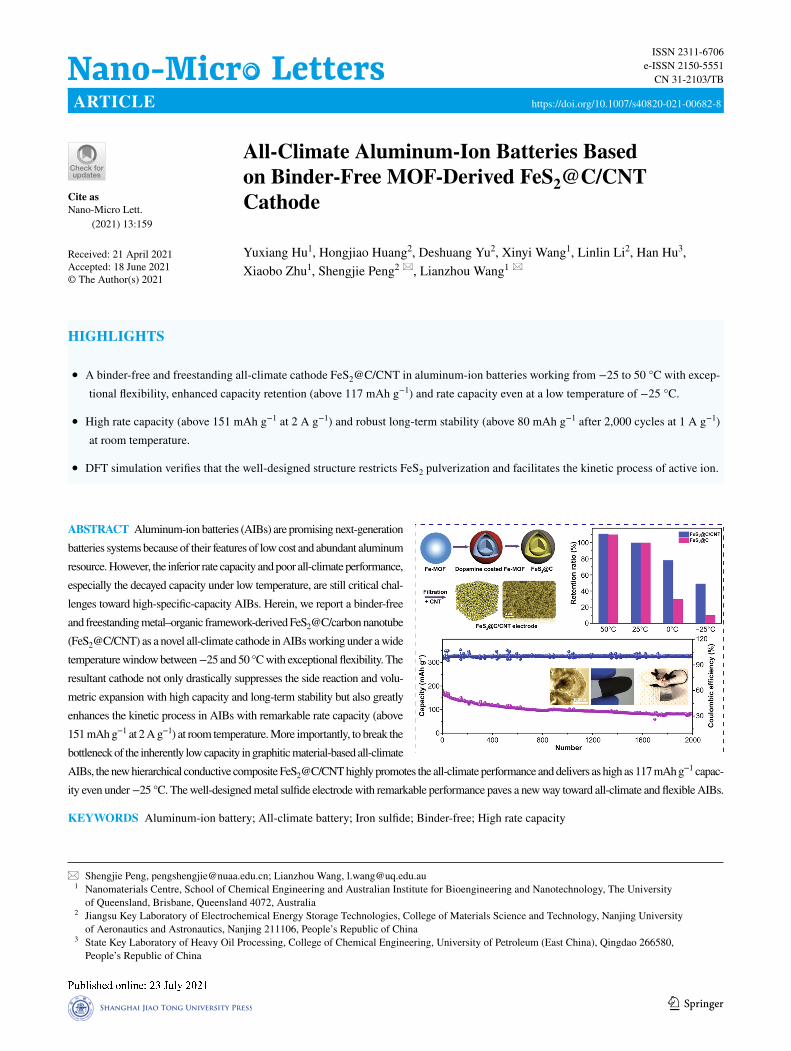
• A binder-free and freestanding all-climate cathode FeS2@C/CNT in aluminum-ion batteries working from −25 to 50 °C with excep-tional flexibility, enhanced capacity retention (above 117 mAh g−1) and rate capacity even at a low temperature of −25 °C.
• High rate capacity (above 151 mAh g−1 at 2 A g−1) and robust long-term stability (above 80 mAh g−1 after 2,000 cycles at 1 A g−1) at room temperature.
• DFT simulation verifies that the well-designed structure restricts FeS2 pulverization and facilitates the kinetic process of active ion.
ABSTRACT Aluminum-ion batteries (AIBs) are promising next-generation batteries systems because of their features of low cost and abundant aluminum resource. However, the inferior rate capacity and poor all-climate performance, especially the decayed capacity under low temperature, are still critical chal-lenges toward high-specific-capacity AIBs. Herein, we report a binder-free and freestanding metal–organic framework-derived FeS2@C/carbon nanotube (FeS2@C/CNT) as a novel all-climate cathode in AIBs working under a wide temperature window between −25 and 50 °C with exceptional flexibility. The resultant cathode not only drastically suppresses the side reaction and volu-metric expansion with high capacity and long-term stability but also greatly enhances the kinetic process in AIBs with remarkable rate capacity (above 151 mAh g−1 at 2 A g−1) at room temperature. More importantly, to break the bottleneck of the inherently low capacity in graphitic material-based all-climate AIBs, the new hierarchical conductive composite FeS2@C/CNT highly promotes the all-climate performance and delivers as high as 117 mAh g−1 capac-ity even under −25 °C. The well-designed metal sulfide electrode with remarkable performance paves a new way toward all-climate and flexible AIBs.
KEYWORDS Aluminum-ion battery; All-climate battery; Iron sulfide; Binder-free; High rate capacity
Nano-Micro Lett. (2021) 13:159 159 Page 2 of 12
https://doi.org/10.1007/s40820-021-00682-8© The authors
1 Introduction
Rechargeable aluminum-ion batteries (AIBs) are promis-ing next-generation batteries with merits of the most abun-dant metal resource on the earth crust, low cost, inherently safe handling, and the highest volumetric capacity (8.04 vs. 2.06 Ah cm−3 of lithium) [1, 2]. Previously, the intrinsic hydrogenation over the Al anode and passive oxide layer for-mation in the aqueous system drastically reduced the battery voltage and efficiency [3–8]; then, ionic liquid (IL) electro-lytes were proposed to avoid these issues in the 2010s [1, 2, 9]. Since then, various cathodes have been proposed in IL-based AIBs including graphite-based materials, metal oxide/sulfide/selenium, MXene, and polymer-based materials to further improve the non-aqueous AIBs [10–15]. Yet, the IL-based AIBs still encountered several critical issues in terms of electrode material disintegration, short-term stability, and poor rate capacity (e.g., most metal sulfide cathodes have low rate capacity) toward practical applications [16, 17]. Therefore, it is highly desirable to construct new structured electrode materials with high capacity, long-term stability, and enhanced rate capability in the rechargeable AIBs.
Moreover, although the newly developed ILs have wide operating temperature window (e.g., from −50 to 80 °C), the development of the all-climate AIBs is severely hindered due to their inherently low capacity [18]. The emerging high-capacity metal sulfide electrodes are promising all-climate candidates, while their low ion/electron conductivity and inferior cycling stability need to be further optimized for all-climate AIBs [18–23]. FeS2, a earth-abundant (pyrite) and low-cost mineral with high theoretical capacity and favorable ion/electron conductivity, is a commercial cathode material in all-climate, especially under low temperatures, lithium batteries (such as Energizer L91) [24–28]. We were inspired to explore the use of FeS2 as an all-climate elec-trode in AIBs, which has not yet been reported.
Herein, we propose the design of a self-standing and binder-free carbon nanotube (CNT) wrapped metal–organic framework (MOF)-derived carbon-coated FeS2 (FeS2@C/CNT) as the high-capacity all-climate metal sulfide cath-ode in AIBs with exceptional flexibility. The binder-free and self-standing yolk–shell structure efficiently eliminates the side reaction between binder/current collector with IL electrolyte and tolerates volume expansion with robust cycling performance (above 80 mAh g−1 after 2,000 cycles
at 1 A g−1). The density functional theory (DFT) simulation also verifies that the well-designed N-doped carbon shell not only restricts FeS2 pulverization but also facilitates the kinetic process of active ion toward FeS2@C/CNT, which is highly beneficial to the capacity/rate capacity (286 mAh g−1 at 100 mA g−1 and even 151 mAh g−1 at 2 A g−1). Moreo-ver, the high conductive carbon matrix and porous struc-ture significantly improve the electron/ion diffusion path-way and electrolyte infiltration with outstanding all-climate performance (−25 to 50 °C), which contribute to enhanced capacity retention (above 117 mAh g−1) and rate capacity even at a low temperature of −25 °C. The novel design of this FeS2@C/CNT paves the potential strategy toward high-performance all-climate and flexible AIBs.
2 Experimental Section
2.1 Chemicals
All chemicals were of analytical grade and used directly without further purification. Polyvinylpyrrolidone (PVP, K30), potassium ferricyanide (K3[Fe(CN)6]), hydrochloric acid (HCl, 36.0% ~ 38.0%), and dopamine hydrochloride were purchased from Sigma-Aldrich. Single-walled carbon nanotube (CNT, P3, > 90% purity) was obtained from car-bon solution, Inc. All the reagents were used without further purification.
2.2 Material Preparation
2.2.1 Yolk–shell Fe‑MOF Spheres
PVP (3.00 g) and K3[Fe(CN)6]·3H2O (132 mg) were added to a 0.01 M HCl solution (40.0 mL) under magnetic stir-ring. After 30 min of stirring, a clear solution was obtained. The vial was then placed into an electric oven and heated at 80 °C for 24 h. After aging, the precipitates were collected by centrifugation and washed several times in distilled water and ethanol. After drying at room temperature for 12 h, Fe-MOF spheres were obtained. To obtain a yolk–shell struc-ture, Fe-MOF (50 mg) and PVP (100 mg) were added to a 2.0 M HCl solution (30 mL) in a Teflon vessel under mag-netic stirring. After 1 h, the vessel was transferred into a stainless autoclave and heated at 140 °C for 4 h. The etching
Nano-Micro Lett. (2021) 13:159 Page 3 of 12 159
1 3
time of 2 and 6 h were also conducted for comparison. After being cooled to room temperature, the precipitate was col-lected by centrifugation, then washed with deionized water and ethanol several times, and finally dried at 60 °C. Finally, yolk–shell Fe-MOF was obtained.
2.2.2 Yolk–shell FeS2@C Spheres
First, 50 mg of yolk–shell Fe-MOF nanocubes and 25 mg of dopamine (DPA) were dispersed into a Tris-buffer solution (80 mL, 10 mM) with magnetic stirring for 3 h. The resultant product was collected via centrifugation and washed three times with deionized water and ethanol, respectively, and dried at 60 °C overnight. Then, the DPA-coated Fe-MOF (Fe-MOF@DPA) and sulfur powder were put at two sepa-rate positions in a porcelain boat with sulfur powder at the upstream side of the furnace. The weight ratio of Fe-MOF@DPA to sulfur is 1:5. After flushed with Ar, the center of the furnace was elevated to 500 °C at a ramping rate of 2 °C min−1, held at this temperature for 2 h, and then natu-rally cooled to ambient temperature under Ar.
2.3 Fabrication of FeS2@C/CNT Electrode and AIBs
The flexible FeS2@C/CNT film was fabricated by the vac-uum filtration method. Firstly, 15 mg of CNT and 35 mg FeS2@C were dispersed in 80 mL H2O using an intensive ultrasonication probe for 30 min. Then, the mixed solu-tion was filtered through a mixed cellulose ester membrane (1.2 µm pore size, Millipore). The obtained filter cake was then vacuum-dried for 24 h to get a freestanding film.
The binder-free and freestanding FeS2@C/CNT directly utilized as a cathode in the AIBs. To compare with com-mercial FeS2, the FeS2 was firstly mixed with KB carbon with the same carbon content in FeS2@C/CNT. Then the mixture and polytetrafluoroethylene (PTFE) (weight ratio of 9:1) mixed in deionized water followed by overnight high-vacuum heating under 100 °C. The areal loading of the active materials is around 1.0 mg cm−2. The 1-ethyl-3-methylimidazolium chloride ([EMIm]Cl, 98%, Sigma) mixed with anhydrous aluminum chloride (99.99%, Sigma-Aldrich) (mole ratio of 1.3) to obtain the ionic liquid (IL) electrolyte (35 μL). A piece of glass fiber was used as the separator (Whatman). The aluminum foil (Sigma, 99.999%, 0.25 mm) is directly treated as the anode electrode. We
applied soft package and Swagelok-type cells to assemble the batteries in glove box filled with Ar gas.
2.4 Materials Characterization & Electrochemical Measurements
The samples were characterized by X-ray diffraction (XRD) (Bruker, Cu Kα, λ = 0.15406 nm, D8-Advance X-ray dif-fractometer,). The transmission electron microscopy (TEM), scanning electron microscopy (SEM) (JEOL-7001), and high-resolution TEM (HR-TEM) (FEI F20 FEG-STEM) were used to characterize the morphology of samples. The contact angles of ILs (drop on glass substrates under vari-ous temperature) were test via optical tensiometer (OCA 15 E/B). The electrochemical performance of the FeS2@C/CNT, and FeS2/C was tested by battery tester (LAND-CT2001A). The cyclic voltammogram (CV) was detected via electrochemical station (CHI 604e Shanghai, China) under a scan rate of 0.2 mV s−1.
2.5 Computational Details
All the DFT calculations were performed with the Per-dew–Burke–Ernzerhof (PBE) functional using the VASP code. The project-augmented wave (PAW) method was applied to represent the core–valence electron interaction [29]. The valence electronic states were expanded in plane wave basis sets with energy cutoff at 500 eV. For the bulk structure, 5 × 5 × 5, 5 × 5 × 3, 4 × 4 × 2 k-point mesh was used for cubic FeS2, hexagonal FeS, and hexagonal Al2S3. The convergence criterion of the total energy was set to be within 1 × 10⁻⁵ eV for the k-point integration and the force thresh-old for the optimization was 0.01 eV Å−1. The ion–electron interaction was described with the PAW method. A FeS2 (001) and graphene slab models were employed to simulate the surface properties. The Monkhorst–Pack method with the centered k-point grid (1 × 2 × 2) was used for surface calculations, respectively. All of the calculations were con-tinued until the force has converged to less than 0.02 eV Å−1, and energies have converged within 10–5 eV.
The hydrogen and water adsorption energy on various surfaces is defined as Eq. (1):
(1)ΔEads
= Ebase−Al
− Ebase
− EAl
Nano-Micro Lett. (2021) 13:159 159 Page 4 of 12
https://doi.org/10.1007/s40820-021-00682-8© The authors
where Ebase−Al
is the total energy of the slab model with Al adsorption, E
base is the energy of a clean slab surface, and
EAl
is that for Al species, which refers to the Al single atom.
3 Results and Discussion
3.1 Synthesis and Characterizations of the FeS2@C/CNT
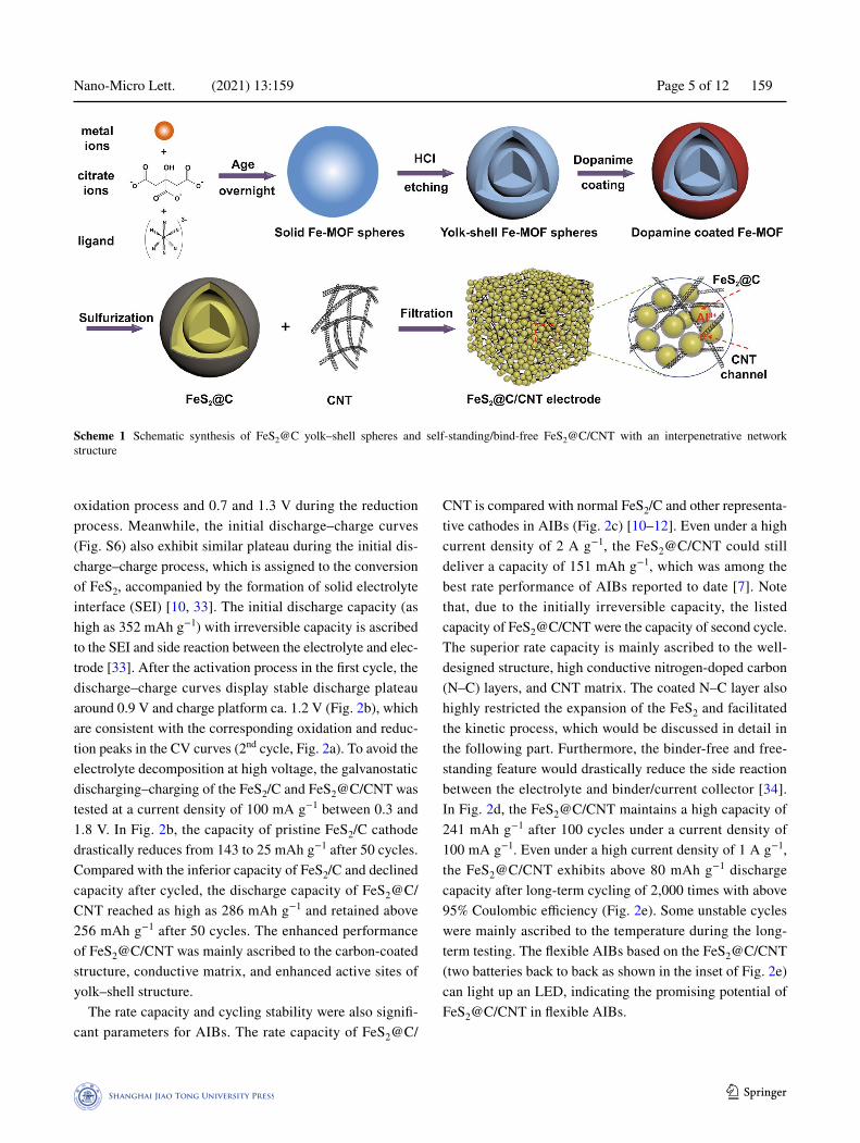
Scheme 1 presents the preparation of the yolk–shell spheres MOF-derived FeS2@C and the binder-free/self-standing FeS2@C/CNT film. The Fe-MOF was prepared via the hydrothermal method (a detailed synthetic condition in the supplementary materials). Then the Fe-MOF was treated in the acidic condition to obtain the yolk–shell hollow Fe-MOF spheres, which enabled abundant active sites to improve the electrolyte infiltration. The dopamine was coated and calcined to improve the electron conductivity of the elec-trode and control the volume expansion during the cycling. After sulfurization, the yolk–shell MOF-derived FeS2@C was obtained. Based on previous literature [12], the com-monly used binders and current collectors have unexpected side reactions with Lewis acid IL electrolyte, which results in capacity decay and material pulverization. To avoid these issues, CNTs were simultaneously prepared with the FeS2@C to obtain binder-free and freestanding FeS2@C/CNT electrode.
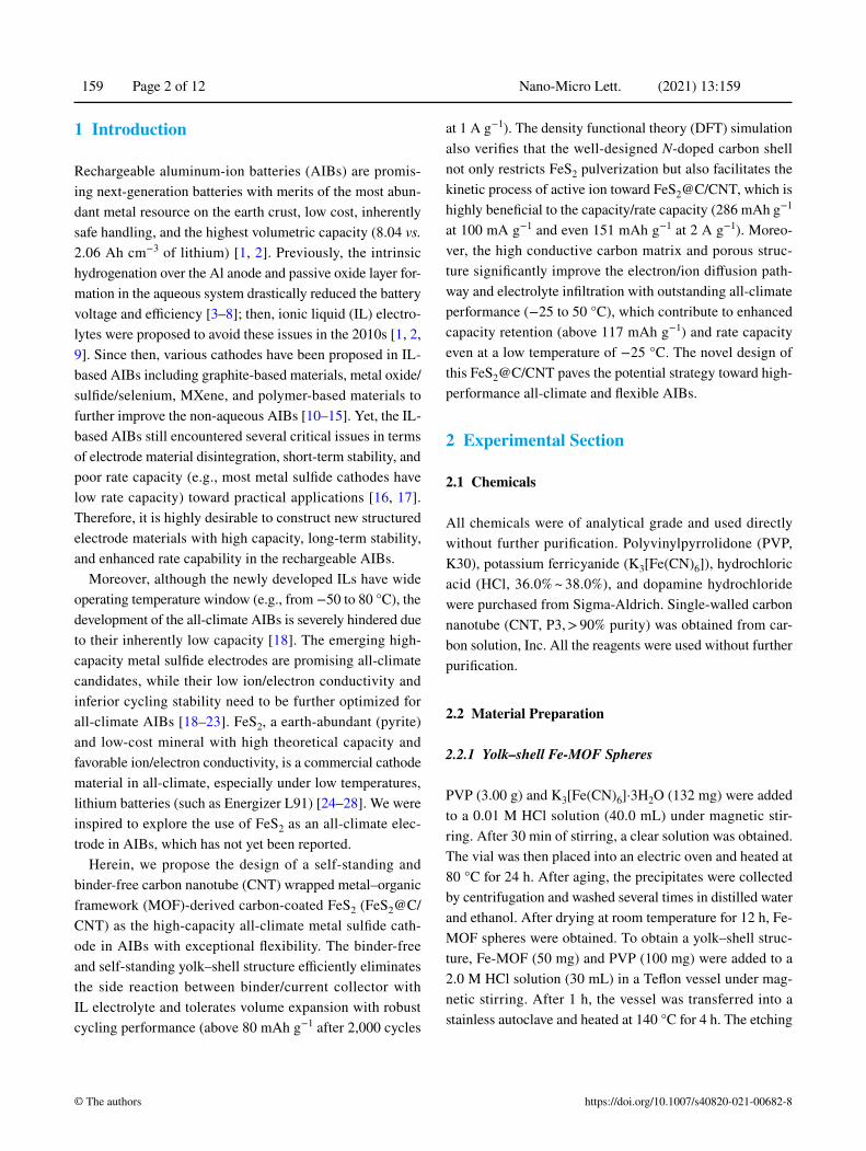
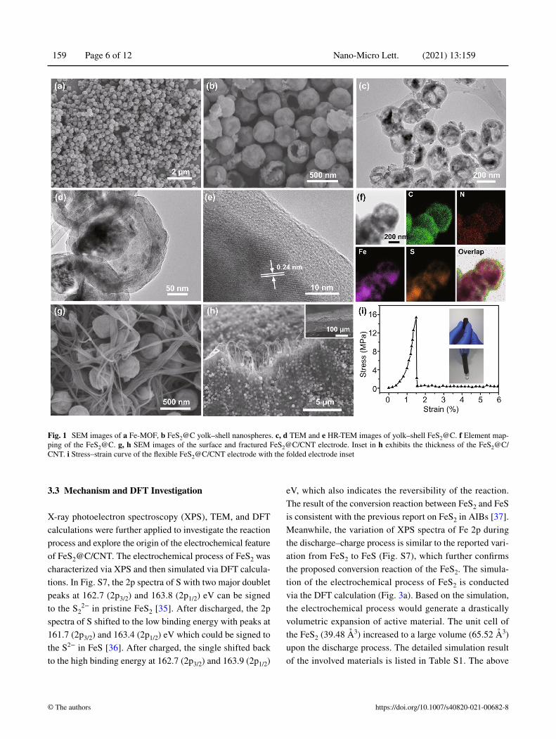
Figure 1a displays the field emission scanning electron microscopy (FE-SEM) of the Fe-MOF. To obtain yolk–shell structure FeS2@C, the pristine solid nanospheres (Fe-MOF, Fig. S1) was etched in acid with different periods. The SEM and TEM images of the etched Fe-MOF (Figs. S2a, b) indi-cate the transformation from solid nanospheres to the hol-low nanospheres after etching. The etching process were optimized via comparing with different conditions. More detailed morphological evolution under different etching stages is presented in Figs. S3 and S4, which was similar to the preparation of other MOF-derived materials [30–32]. As the etching time increases, the structure of the original Fe-MOF was gradually destroyed. After 2 h, a yolk–shell structure was formed based on the original Fe-MOF (Fig. S3). The cavity became larger after 4 h (Fig. S2), and each of the resultant samples possessed a spherical yolk–shell structure. After 6 h of etching, some of the particles were destroyed and a large interior hollow cavity was formed in
the center of the Fe-MOF (Fig. S4). In order to maintain the complete and uniform structure of the material as well as reserve suitable space for the volume expansion of FeS2 sulfide during the cycling, 4 h of etching was selected as the optimal solution. Figure 1b shows the SEM image of dopa-mine-coated and sulfurized material (FeS2@C), which still maintains similar nanospheres morphology with the previ-ous Fe-MOF. The TEM images of the FeS2@C (Figs. 1c, d) exhibit the yolk–shell hollow structure. The HR-TEM image shows a thin layer of carbon-coated on the surface of the crystal FeS2 (Fig. 1e). Moreover, a set of lattice fringes with d-spacing of 0.24 nm that are associated with the (210) plane of FeS2 crystals (JCPDS No. 42–1340) can be observed. The EDS mapping of the FeS2@C (Fig. 1f) not only indicates that Fe, S, N, and C elements are homogeneously distributed throughout the hollow yolk-sheath material but also confirms the nitrogen-doped sheath derived from the dopamine [12]. Based on the thermal gravimetric analysis data (Fig. S5), the mass content of carbon in FeS2@C is around 10 wt%. The XRD pattern of the product also proves that the obtained production with the characteristic peaks (Fig. S5) matches with the standard FeS2 phase (JCPDS No. 65–1765).
The binder-free and self-standing FeS2@C/CNT elec-trode is shown in the SEM image (Fig. 1g). The nanosphere FeS2@C was surrounded by the CNT substrate. The cross-view structure of the FeS2@C/CNT (Fig. 1h) also exhibits the homogenous distribution of the FeS2 particle among the CNT. The thickness of the FeS2@C/CNT, which can be controlled via modifying the added raw materials during the filtration process, is around 100 μm (inset of Fig. 1h). Moreover, the mechanical property of the FeS2@C/CNT is presented in the stress–strain curve (Fig. 1i). Maximum stretch stress (15 MPa) was achieved at the strain percent-age of 1.4%. The considerable mechanical properties of the tested sample proved the enhanced flexible feature of this electrode.
3.2 Electrochemical Performance of FeS2@C/CNT
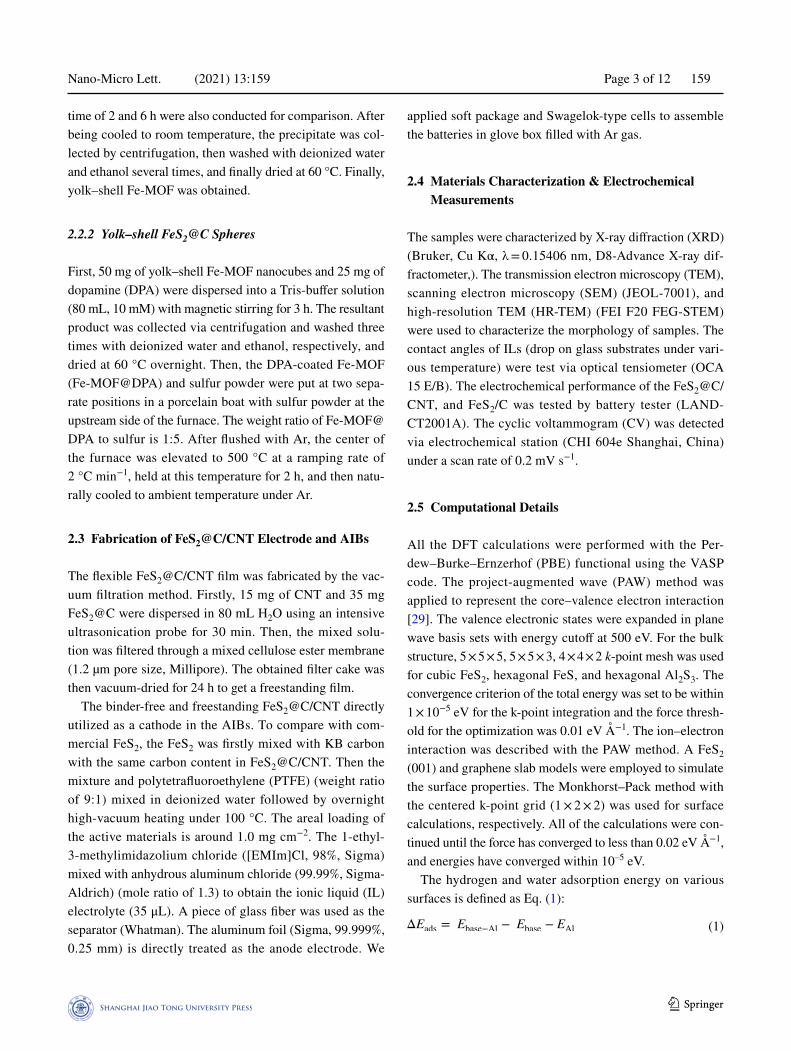
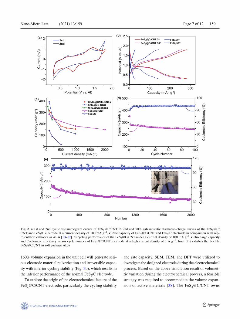
The electrochemical performances of the FeS2@C/CNT and normal FeS2 with carbon mixture electrode (FeS2/C) cath-odes under room temperature are presented in Fig. 2. The cyclic voltammogram (CV) of the FeS2@C/CNT (Fig. 2a), which is conducted at 0.2 mV s−1, exhibits the initial cycle with weak peaks around 1.2 and 0.6 V during the anodic
Nano-Micro Lett. (2021) 13:159 Page 5 of 12 159
1 3
oxidation process and 0.7 and 1.3 V during the reduction process. Meanwhile, the initial discharge–charge curves (Fig. S6) also exhibit similar plateau during the initial dis-charge–charge process, which is assigned to the conversion of FeS2, accompanied by the formation of solid electrolyte interface (SEI) [10, 33]. The initial discharge capacity (as high as 352 mAh g−1) with irreversible capacity is ascribed to the SEI and side reaction between the electrolyte and elec-trode [33]. After the activation process in the first cycle, the discharge–charge curves display stable discharge plateau around 0.9 V and charge platform ca. 1.2 V (Fig. 2b), which are consistent with the corresponding oxidation and reduc-tion peaks in the CV curves (2nd cycle, Fig. 2a). To avoid the electrolyte decomposition at high voltage, the galvanostatic discharging–charging of the FeS2/C and FeS2@C/CNT was tested at a current density of 100 mA g−1 between 0.3 and 1.8 V. In Fig. 2b, the capacity of pristine FeS2/C cathode drastically reduces from 143 to 25 mAh g−1 after 50 cycles. Compared with the inferior capacity of FeS2/C and declined capacity after cycled, the discharge capacity of FeS2@C/CNT reached as high as 286 mAh g−1 and retained above 256 mAh g−1 after 50 cycles. The enhanced performance of FeS2@C/CNT was mainly ascribed to the carbon-coated structure, conductive matrix, and enhanced active sites of yolk–shell structure.
The rate capacity and cycling stability were also signifi-cant parameters for AIBs. The rate capacity of FeS2@C/
CNT is compared with normal FeS2/C and other representa-tive cathodes in AIBs (Fig. 2c) [10–12]. Even under a high current density of 2 A g−1, the FeS2@C/CNT could still deliver a capacity of 151 mAh g−1, which was among the best rate performance of AIBs reported to date [7]. Note that, due to the initially irreversible capacity, the listed capacity of FeS2@C/CNT were the capacity of second cycle. The superior rate capacity is mainly ascribed to the well-designed structure, high conductive nitrogen-doped carbon (N–C) layers, and CNT matrix. The coated N–C layer also highly restricted the expansion of the FeS2 and facilitated the kinetic process, which would be discussed in detail in the following part. Furthermore, the binder-free and free-standing feature would drastically reduce the side reaction between the electrolyte and binder/current collector [34]. In Fig. 2d, the FeS2@C/CNT maintains a high capacity of 241 mAh g−1 after 100 cycles under a current density of 100 mA g−1. Even under a high current density of 1 A g−1, the FeS2@C/CNT exhibits above 80 mAh g−1 discharge capacity after long-term cycling of 2,000 times with above 95% Coulombic efficiency (Fig. 2e). Some unstable cycles were mainly ascribed to the temperature during the long-term testing. The flexible AIBs based on the FeS2@C/CNT (two batteries back to back as shown in the inset of Fig. 2e) can light up an LED, indicating the promising potential of FeS2@C/CNT in flexible AIBs.
Scheme 1 Schematic synthesis of FeS2@C yolk–shell spheres and self-standing/bind-free FeS2@C/CNT with an interpenetrative network structure
Nano-Micro Lett. (2021) 13:159 159 Page 6 of 12
https://doi.org/10.1007/s40820-021-00682-8© The authors
3.3 Mechanism and DFT Investigation
X-ray photoelectron spectroscopy (XPS), TEM, and DFT calculations were further applied to investigate the reaction process and explore the origin of the electrochemical feature of FeS2@C/CNT. The electrochemical process of FeS2 was characterized via XPS and then simulated via DFT calcula-tions. In Fig. S7, the 2p spectra of S with two major doublet peaks at 162.7 (2p3/2) and 163.8 (2p1/2) eV can be signed to the S2
2− in pristine FeS2 [35]. After discharged, the 2p spectra of S shifted to the low binding energy with peaks at 161.7 (2p3/2) and 163.4 (2p1/2) eV which could be signed to the S2− in FeS [36]. After charged, the single shifted back to the high binding energy at 162.7 (2p3/2) and 163.9 (2p1/2)
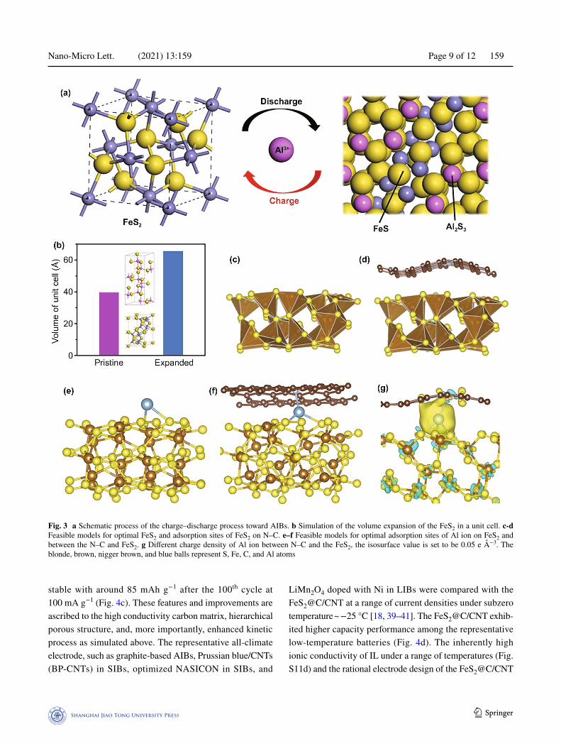
eV, which also indicates the reversibility of the reaction. The result of the conversion reaction between FeS2 and FeS is consistent with the previous report on FeS2 in AIBs [37]. Meanwhile, the variation of XPS spectra of Fe 2p during the discharge–charge process is similar to the reported vari-ation from FeS2 to FeS (Fig. S7), which further confirms the proposed conversion reaction of the FeS2. The simula-tion of the electrochemical process of FeS2 is conducted via the DFT calculation (Fig. 3a). Based on the simulation, the electrochemical process would generate a drastically volumetric expansion of active material. The unit cell of the FeS2 (39.48 Å3) increased to a large volume (65.52 Å3) upon the discharge process. The detailed simulation result of the involved materials is listed in Table S1. The above
Fig. 1 SEM images of a Fe-MOF, b FeS2@C yolk–shell nanospheres. c, d TEM and e HR-TEM images of yolk–shell FeS2@C. f Element map-ping of the FeS2@C. g, h SEM images of the surface and fractured FeS2@C/CNT electrode. Inset in h exhibits the thickness of the FeS2@C/CNT. i Stress–strain curve of the flexible FeS2@C/CNT electrode with the folded electrode inset
Nano-Micro Lett. (2021) 13:159 Page 7 of 12 159
1 3
160% volume expansion in the unit cell will generate seri-ous electrode material pulverization and irreversible capac-ity with inferior cycling stability (Fig. 3b), which results in the inferior performance of the normal FeS2/C electrode.
To explore the origin of the electrochemical feature of the FeS2@C/CNT electrode, particularly the cycling stability
and rate capacity, SEM, TEM, and DFT were utilized to investigate the designed electrode during the electrochemical process. Based on the above simulation result of volumet-ric variation during the electrochemical process, a feasible strategy was required to accommodate the volume expan-sion of active materials [38]. The FeS2@C/CNT owns
(a)
(c)
(b)
(d)
(e)
Cap
acity
(mAh
g-1)
300
200
100
00 400 800 1200 1600 2000
Number
Cou
lom
bic
Effic
ienc
y (%
)
120
90
60
30C
oulo
mbi
c Ef
ficie
ncy
(%)
120
90
60
30
00 20 40 60 80 100
Cycle Number
Cap
acity
(mAh
g-1)
Cap
acity
(mAh
g-1)
500
400
300
200
100
400
300
200
100
00 500 1000 1500 2000
Current density (mA g-1)
Potential (V vs. AI) Capacity (mAh g-1)0 100 200 300
0.0
0.5
1.0
1.5
2.0
2.5
Pote
ntia
l (V
vs. A
l)
2.01.51.00.5
−2
−1
0
1
2C
urre
nt (m
A)1st2nd
FeS2@C/CNT 2nd FeS2 2nd
FeS2@C/CNT 50th FeS2 50th
SnS2@3D-RGONi3S2@Graphene
Co9S8@CNTs-CNFs
FeS2/CFeS2@C/CNT
Fig. 2 a 1st and 2nd cyclic voltammogram curves of FeS2@C/CNT. b 2nd and 50th galvanostatic discharge–charge curves of the FeS2@C/CNT and FeS2/C electrode at a current density of 100 mA g−1. c Rate capacity of FeS2@C/CNT and FeS2/C electrode in comparison with rep-resentative cathodes in AIBs [10–12]. d Cycling performance of the FeS2@C/CNT under a current density of 100 mA g−1. e Discharge capacity and Coulombic efficiency versus cycle number of FeS2@C/CNT electrode at a high current density of 1 A g−1. Inset of e exhibits the flexible FeS2@C/CNT in soft package AIBs
Nano-Micro Lett. (2021) 13:159 159 Page 8 of 12
https://doi.org/10.1007/s40820-021-00682-8© The authors
not only the yolk–shell structure but also extra void space (Fig. 1d). Thus, this yolk–shell structure with the outermost carbon layer restrained the expansion of the active mate-rial and stabilized the electrode. The void space inside was sufficient to tolerate the volume variation, which was also beneficial to the electrode stability. Figure 3c, d shows the optimal FeS2 and the loading of FeS2 on the N-doped car-bon, which is corresponding to the N-doped carbon layer in FeS2@C/CNT models. The obvious folded structure of the N–C layer revealed the strong interaction between FeS2 and N–C, which also effectively reduced the FeS2 splitting up from the carbon structure and active material pulverization. Furthermore, the morphology of FeS2@C/CNT after 50th and 200th cycles (Fig. S8) are slightly cracked compared with the initial sample (Fig. 1d), which confirms the simula-tion results on this stable yolk–shell FeS2@C/CNT. On the contrary, the micro-FeS2 in the normal FeS2/C electrode is seriously degenerated after cycling with obvious cracking and pulverization (Figs. S9 and S10).
To better understand the kinetic process during the elec-trochemical reaction and enhanced rate capacity, the simu-lation of absorption of aluminum ion on pristine FeS2 and FeS2@N–C/CNT was conducted to reveal the advantage of the designed structure. Based on the simulation result (Figs. 3e, f), the aluminum ion between the N–C layer and FeS2 has much strong adsorption energy (−1.76 eV) in comparison with the bare FeS2 module (−1.41 eV) as shown in Table S2. The lower adsorption energy indicates the strengthened reaction process when Al ion involved, which is beneficial for the rate capacity of FeS2@N–C/CNT. Meanwhile, in Fig. 4g, when the Al locates between FeS2 and N–C, the charge accumulation (yellow ball) can be observed, which illustrates the obvious electron transfer within Al and FeS2/N–C and further proves the strong inter-action between them. Based on the above characterization and simulation, the well-designed FeS2@C/CNT not only prevents the agglomeration of FeS2 particles during cycling but also accelerates the reaction process, contributing to the robust cycling and high rate capacity.
3.4 All‑climate Performance of FeS2@C/CNT in AIBs
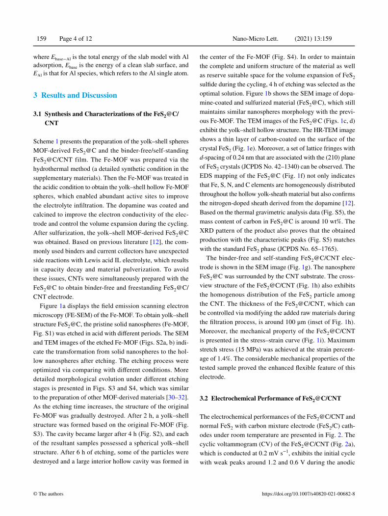
Most of the studies on AIBs to date focus on room tempera-ture or high-temperature electrochemical performance [37, 42]. Although the graphite-based AIBs have a considerable
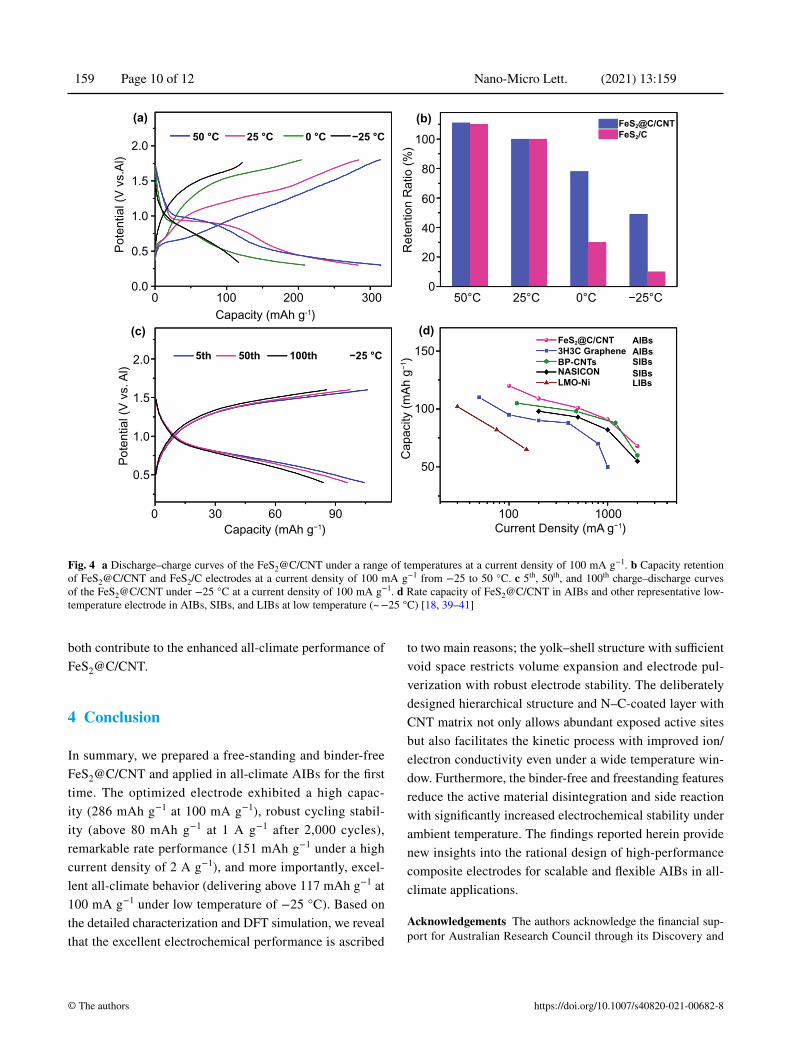
process under a wide temperature range, the inherently limited capacity (less than 150 mAh g−1 even at high tem-perature) still hinders the development of all-climate AIB, especially under low temperature [8]. Thus, emerging high-capacity metal chalcogenide-based electrodes, such as metal sulfides, were worth exploring, yet few reported. Based on the inherent ion-conductivity of FeS2, enhanced perfor-mance at room temperature, and above simulation of the kinetic process of the FeS2@C/CNT cathode, the battery performance of FeS2@C/CNT under all-climate, especially for the cold climate, was further investigated in detail. The inherent advantage of the IL-based AIBs contributed to enhanced electrochemical performance under low tempera-ture. The contact angle of IL only increased from 55 to 64° when the temperature reduced from 25 to −25 °C (Figs. S11a-c). On the contrary, the considerable organic solvent-based electrolyte of LIBs and SIBs froze at −25 °C [43]. The wettability experiment of IL indicates that the stable infiltration of the IL under a range of temperatures from subzero to room temperature. Moreover, the IL electrolyte also shows stable ion conductivity under a range of tempera-tures (Fig. S11d). In Fig. 3a, the discharge–charge curves of the FeS2@C/CNT are exhibited under the temperature from −25 to 50 °C. Although the previous literature has reported the inferior cycling stability of batteries at high tempera-ture [39], the FeS2@C/CNT exhibits stable capacity and Coulombic efficiency at 50 °C (Fig. S12), which is ascribed to the void yolk–shell structure and well-protected carbon layer to prevent the materials pulverization and side reaction. Owing to the reduced ion conductivity of the electrolyte and the inherently kinetic process on cathode/electrolyte under low temperature [40], the battery performance of FeS2/C drastically reduced under low temperature. However, the FeS2@C/CNT exhibit comparable high capacity retention even under −25 °C (above 117 mAh g−1 at 100 mA g−1, Figs. 4a, b). When compared with that of normal FeS2/C (only 10% capacity retention under −25 °C), the FeS2@C/CNT exhibited much higher capacity retention (above four times higher than that of FeS2/C). Although low tempera-ture with slow kinetic process reduced the stability of the discharge–charge plateau, the MOF-derived carbon on FeS2, CNT matrix and hollow structure still largely enhanced the high conductivity and kinetic process of FeS2@C/CNT in compared with FeS2/C. Furthermore, the cycling stability of the FeS2@C/CNT under low temperature still maintains
Nano-Micro Lett. (2021) 13:159 Page 9 of 12 159
1 3
stable with around 85 mAh g−1 after the 100th cycle at 100 mA g−1 (Fig. 4c). These features and improvements are ascribed to the high conductivity carbon matrix, hierarchical porous structure, and, more importantly, enhanced kinetic process as simulated above. The representative all-climate electrode, such as graphite-based AIBs, Prussian blue/CNTs (BP-CNTs) in SIBs, optimized NASICON in SIBs, and
LiMn2O4 doped with Ni in LIBs were compared with the FeS2@C/CNT at a range of current densities under subzero temperature ~ −25 °C [18, 39–41]. The FeS2@C/CNT exhib-ited higher capacity performance among the representative low-temperature batteries (Fig. 4d). The inherently high ionic conductivity of IL under a range of temperatures (Fig. S11d) and the rational electrode design of the FeS2@C/CNT
Fig. 3 a Schematic process of the charge–discharge process toward AIBs. b Simulation of the volume expansion of the FeS2 in a unit cell. c‑d Feasible models for optimal FeS2 and adsorption sites of FeS2 on N–C. e–f Feasible models for optimal adsorption sites of Al ion on FeS2 and between the N–C and FeS2. g Different charge density of Al ion between N–C and the FeS2, the isosurface value is set to be 0.05 e Å−3. The blonde, brown, nigger brown, and blue balls represent S, Fe, C, and Al atoms
Nano-Micro Lett. (2021) 13:159 159 Page 10 of 12
https://doi.org/10.1007/s40820-021-00682-8© The authors
both contribute to the enhanced all-climate performance of FeS2@C/CNT.
4 Conclusion
In summary, we prepared a free-standing and binder-free FeS2@C/CNT and applied in all-climate AIBs for the first time. The optimized electrode exhibited a high capac-ity (286 mAh g−1 at 100 mA g−1), robust cycling stabil-ity (above 80 mAh g−1 at 1 A g−1 after 2,000 cycles), remarkable rate performance (151 mAh g−1 under a high current density of 2 A g−1), and more importantly, excel-lent all-climate behavior (delivering above 117 mAh g−1 at 100 mA g−1 under low temperature of −25 °C). Based on the detailed characterization and DFT simulation, we reveal that the excellent electrochemical performance is ascribed
to two main reasons; the yolk–shell structure with sufficient void space restricts volume expansion and electrode pul-verization with robust electrode stability. The deliberately designed hierarchical structure and N–C-coated layer with CNT matrix not only allows abundant exposed active sites but also facilitates the kinetic process with improved ion/electron conductivity even under a wide temperature win-dow. Furthermore, the binder-free and freestanding features reduce the active material disintegration and side reaction with significantly increased electrochemical stability under ambient temperature. The findings reported herein provide new insights into the rational design of high-performance composite electrodes for scalable and flexible AIBs in all-climate applications.
Acknowledgements The authors acknowledge the financial sup-port for Australian Research Council through its Discovery and
Capacity (mAh g−1) Current Density (mA g−1)
Pote
ntia
l (V
vs. A
l)Po
tent
ial (
V vs
.Al)
Cap
acity
(mAh
g−1
)2.0
1.5
1.0
0.5
2.0
1.5
1.0
0.5
0.0
0 30 60 90
Capacity (mAh g-1)
FeS2@C/CNT
FeS2/CFeS2@C/CNT
3H3C GrapheneBP-CNTsNASICONLMO-Ni LIBs
SIBsSIBsAIBsAIBs
100
150
100
50
100 0030020
1000
Ret
entio
n R
atio
(%) 100
80
60
40
20
050°C
50 °C 25 °C 0 °C −25 °C
25°C 0°C −25°C
5th 50th 100th −25 °C
(a)
(c) (d)
(b)
Fig. 4 a Discharge–charge curves of the FeS2@C/CNT under a range of temperatures at a current density of 100 mA g−1. b Capacity retention of FeS2@C/CNT and FeS2/C electrodes at a current density of 100 mA g−1 from −25 to 50 °C. c 5th, 50th, and 100th charge–discharge curves of the FeS2@C/CNT under −25 °C at a current density of 100 mA g−1. d Rate capacity of FeS2@C/CNT in AIBs and other representative low-temperature electrode in AIBs, SIBs, and LIBs at low temperature (~ −25 °C) [18, 39–41]
Nano-Micro Lett. (2021) 13:159 Page 11 of 12 159
1 3
Linkage Programs. This work was performed in part at Australian Microscopy & Microanalysis Research Facility at the Centre for Microscopy and Microanalysis, the University of Queensland (UQ). The authors also acknowledge National Natural Science Foundation of China (51901100 and 51871119), Jiangsu Provincial Founds for Natural Science Foundation (BK20180015), China Postdoc-toral Science Foundation (2018M640481 and 2019T120426), and Jiangsu Postdoctoral Research Fund (2019K003).
Open Access This article is licensed under a Creative Commons Attribution 4.0 International License, which permits use, sharing, adaptation, distribution and reproduction in any medium or format, as long as you give appropriate credit to the original author(s) and the source, provide a link to the Creative Commons licence, and indicate if changes were made. The images or other third party material in this article are included in the article’s Creative Com-mons licence, unless indicated otherwise in a credit line to the material. If material is not included in the article’s Creative Com-mons licence and your intended use is not permitted by statutory regulation or exceeds the permitted use, you will need to obtain permission directly from the copyright holder. To view a copy of this licence, visit http:// creat iveco mmons. org/ licen ses/ by/4. 0/.
Supplementary Information The online version contains supplementary material available at https:// doi. org/ 10. 1007/ s40820- 021- 00682-8.
References
1. Q. Zhao, M.J. Zachman, W.I. Al Sadat, J. Zheng, L.F. Kourk-outis et al., Solid electrolyte interphases for high-energy aqueous aluminum electrochemical cells. Sci. Adv. 4(11), eaau8131 (2018). https:// doi. org/ 10. 1126/ sciadv. aau81 31
2. M.C. Lin, M. Gong, B. Lu, Y. Wu, D.Y. Wang et al., An ultra-fast rechargeable aluminium-ion battery. Nature 520(7547), 325–328 (2015). https:// doi. org/ 10. 1038/ natur e14340
3. F. Ambroz, T.J. Macdonald, T. Nann, Trends in aluminium-based intercalation batteries. Adv. Energy Mater. 7(15), 1602093 (2017). https:// doi. org/ 10. 1002/ aenm. 20160 2093
4. Y. Zhang, S. Liu, Y. Ji, J. Ma, H. Yu, Emerging nonaqueous aluminum-ion batteries: Challenges, status, and perspectives. Adv. Mater. 30(38), e1706310 (2018). https:// doi. org/ 10. 1002/ adma. 20170 6310
5. Q. Li, N.J. Bjerrum, Aluminum as anode for energy stor-age and conversion: a review. J. Power Sources 110(1), 1–10 (2002). https:// doi. org/ 10. 1016/ S0378- 7753(01) 01014-X
6. G.A. Elia, K. Marquardt, K. Hoeppner, S. Fantini, R. Lin et al., An overview and future perspectives of aluminum batteries. Adv. Mater. 28(35), 7564–7579 (2016). https:// doi. org/ 10. 1002/ adma. 20160 1357
7. Y.X. Hu, D. Sun, B. Luo, L.Z. Wang, Recent progress and future trends of aluminum batteries. Energy Technol. 7(1), 86–106 (2019). https:// doi. org/ 10. 1002/ ente. 20180 0550
8. S.K. Das, S. Mahapatra, H. Lahan, Aluminium-ion batter-ies: developments and challenges. J. Mater. Chem. A 5(14), 6347–6367 (2017). https:// doi. org/ 10. 1039/ C7TA0 0228A
9. H. Sun, W. Wang, Z. Yu, Y. Yuan, S. Wang et al., A new aluminium-ion battery with high voltage, high safety and low cost. Chem. Commun. 51(59), 11892–11895 (2015). https:// doi. org/ 10. 1039/ C5CC0 0542F
10. S. Wang, Z. Yu, J. Tu, J. Wang, D. Tian et al., A novel alu-minum-ion battery: Al/AlCl3-[EMIM]Cl/Ni3S2@graphene. Adv. Energy Mater. 6(13), 1600137 (2016). https:// doi. org/ 10. 1002/ aenm. 20160 0137
11. Y. Hu, B. Luo, D. Ye, X. Zhu, M. Lyu et al., An innovative freeze-dried reduced graphene oxide supported SnS2 cathode active material for aluminum-ion batteries. Adv. Mater. 29(48), 1606132 (2017). https:// doi. org/ 10. 1002/ adma. 20160 6132
12. Y. Hu, D. Ye, B. Luo, H. Hu, X. Zhu et al., A binder-free and free-standing cobalt sulfide@carbon nanotube cathode mate-rial for aluminum-ion batteries. Adv. Mater. 30(2), 1703824 (2018). https:// doi. org/ 10. 1002/ adma. 20170 3824
13. D.J. Kim, D.-J. Yoo, M.T. Otley, A. Prokofjevs, C. Pezzato et al., Rechargeable aluminium organic batteries. Nat. Energy 4, 51–59 (2018). https:// doi. org/ 10. 1038/ s41560- 018- 0291-0
14. N.S. Hudak, Chloroaluminate-doped conducting polymers as positive electrodes in rechargeable aluminum batteries. J. Phys. Chem. C 118(10), 5203–5215 (2014). https:// doi. org/ 10. 1021/ jp500 593d
15. Y.X. Hu, Y. Bai, B. Luo, S.C. Wang, H. Hu et al., A portable and efficient solar-rechargeable battery with ultrafast photo-charge/discharge rate. Adv. Energy Mater. 9(28), 1900872 (2019). https:// doi. org/ 10. 1002/ aenm. 20190 0872
16. S. Jiao, H. Lei, J. Tu, J. Zhu, J. Wang et al., An industrialized prototype of the rechargeable Al/AlCl3-[EMIM]Cl/graphite battery and recycling of the graphitic cathode into graphene. Carbon 109, 276–281 (2016). https:// doi. org/ 10. 1016/j. car-bon. 2016. 08. 027
17. L. Fu, N. Li, Y. Liu, W. Wang, Y. Zhu et al., Advances of alu-minum based energy storage systems. Chin. J. Chem. 35(1), 13–20 (2017). https:// doi. org/ 10. 1002/ cjoc. 20160 0655
18. H. Chen, H. Xu, S. Wang, T. Huang, J. Xi et al., Ultrafast all-climate aluminum-graphene battery with quarter-million cycle life. Sci. Adv. 3(12), eaao7233 (2017). https:// doi. org/ 10. 1126/ sciadv. aao72 33
19. Z. Liu, J. Wang, H. Ding, S. Chen, X. Yu et al., Carbon nanoscrolls for aluminum battery. ACS Nano 12(8), 8456–8466 (2018). https:// doi. org/ 10. 1021/ acsna no. 8b039 61
20. X. Feng, X. He, W. Pu, C. Jiang, C. Wan, Hydrothermal syn-thesis of FeS2 for lithium batteries. Ionics 13(5), 375–377 (2007). https:// doi. org/ 10. 1007/ s11581- 007- 0136-5
21. B.Y. Guan, X.Y. Yu, H.B. Wu, X.W. Lou, Complex nano-structures from materials based on metal–organic frame-works for electrochemical energy storage and conversion. Adv. Mater. 29(47), 1703614 (2017). https:// doi. org/ 10. 1002/ adma. 20170 3614
22. X.-Y. Yu, L. Yu, X.W. Lou, Metal sulfide hollow nanostruc-tures for electrochemical energy storage. Adv. Energy Mater.
Nano-Micro Lett. (2021) 13:159 159 Page 12 of 12
https://doi.org/10.1007/s40820-021-00682-8© The authors
6(3), 1501333 (2016). https:// doi. org/ 10. 1002/ aenm. 20150 1333
23. Y. Ding, Y. Chen, N. Xu, X. Lian, L. Li et al., Facile syn-thesis of FePS3 nanosheets@Mxene composite as a high-performance anode material for sodium storage. Nano-Micro Lett. 12(1), 54 (2020). https:// doi. org/ 10. 1007/ s40820- 020- 0381-y
24. S.S. Zhang, D.T. Tran, Mechanism and solution for the capac-ity fading of Li/FeS2 battery. J. Electrochem. Soc. 163(5), A792–A797 (2016). https:// doi. org/ 10. 1149/2. 00416 06jes
25. M. Walter, T. Zünd, M.V. Kovalenko, Pyrite (FeS2) nanocrys-tals as inexpensive high-performance lithium-ion cathode and sodium-ion anode materials. Nanoscale 7(20), 9158–9163 (2015). https:// doi. org/ 10. 1039/ C5NR0 0398A
26. Y. Shao-Horn, S. Osmialowski, Q.C. Horn, Nano- FeS2 for commercial Li/FeS2 primary batteries. J. Electrochem. Soc. 149(11), A1499 (2002). https:// doi. org/ 10. 1149/1. 15135 58
27. Z. Hu, Z. Zhu, F. Cheng, K. Zhang, J. Wang et al., Pyrite FeS2 for high-rate and long-life rechargeable sodium batteries. Energy Environ. Sci. 8(4), 1309–1316 (2015). https:// doi. org/ 10. 1039/ C4EE0 3759F
28. Z. Zhao, Z. Hu, R. Jiao, Z. Tang, P. Dong et al., Tailor-ing multi-layer architectured FeS2@C hybrids for superior sodium-, potassium- and aluminum-ion storage. Energy Stor-age Mater. 22, 228–234 (2019). https:// doi. org/ 10. 1016/j. ensm. 2019. 01. 022
29. P.E. Blöchl, Projector augmented-wave method. Phy. Rev. B 50(24), 17953–17979 (1994). https:// doi. org/ 10. 1103/ PhysR evB. 50. 17953
30. C.-J. Yao, Z. Wu, J. Xie, F. Yu, W. Guo et al., Two-dimen-sional (2D) covalent organic framework as efficient cathode for binder-free lithium-ion battery. Chemsuschem 13(9), 2457–2463 (2020). https:// doi. org/ 10. 1002/ cssc. 20190 3007
31. Z. Wu, J. Xie, Z.J. Xu, S. Zhang, Q. Zhang, Recent progress in metal–organic polymers as promising electrodes for lithium/sodium rechargeable batteries. J. Mater. Chem. A 7(9), 4259–4290 (2019). https:// doi. org/ 10. 1039/ C8TA1 1994E
32. Z. Wu, D. Adekoya, X. Huang, M.J. Kiefel, J. Xie et al., Highly conductive two-dimensional metal–organic frame-works for resilient lithium storage with superb rate capability. ACS Nano 14(9), 12016–12026 (2020). https:// doi. org/ 10. 1021/ acsna no. 0c052 00
33. Y.-X. Wang, J. Yang, S.-L. Chou, H.K. Liu, W.-X. Zhang et al., Uniform yolk-shell iron sulfide–carbon nanospheres for
superior sodium–iron sulfide batteries. Nat. Commun. 6, 8689 (2015). https:// doi. org/ 10. 1038/ ncomm s9689
34. L.D. Reed, E. Menke, The roles of V2O5 and stainless steel in rechargeable al-ion batteries. J. Electrochem. Soc. 160(6), A915–A917 (2013). https:// doi. org/ 10. 1149/2. 11430 6jes
35. Y. Liang, P. Bai, J. Zhou, T. Wang, B. Luo et al., An efficient precursor to synthesize various FeS2 nanostructures via a sim-ple hydrothermal synthesis method. CrystEngComm 18(33), 6262–6271 (2016). https:// doi. org/ 10. 1039/ C6CE0 1203E
36. D. Shao, X. Wang, J. Li, Y. Huang, X. Ren et al., Reductive immobilization of uranium by PAAM–FeS/Fe3O4 magnetic composites. Environ. Sci-Wat Res. 1(2), 169–176 (2015). https:// doi. org/ 10. 1039/ C4EW0 0014E
37. T. Mori, Y. Orikasa, K. Nakanishi, C. Kezheng, M. Hattori et al., Discharge/charge reaction mechanisms of FeS2 cathode material for aluminum rechargeable batteries at 55°C. J. Power Sources 313, 9–14 (2016). https:// doi. org/ 10. 1016/j. jpows our. 2016. 02. 062
38. S. Peng, F. Gong, L. Li, D. Yu, D. Ji et al., Necklace-like multishelled hollow spinel oxides with oxygen vacancies for efficient water electrolysis. J. Am. Chem. Soc. 140(42), 13644–13653 (2018). https:// doi. org/ 10. 1021/ jacs. 8b051 34
39. T. Liu, B. Wang, X. Gu, L. Wang, M. Ling et al., All-climate sodium ion batteries based on the nasicon electrode materials. Nano Energy 30, 756–761 (2016). https:// doi. org/ 10. 1016/j. nanoen. 2016. 09. 024
40. Y. You, H.-R. Yao, S. Xin, Y.-X. Yin, T.-T. Zuo et al., Subzero-temperature cathode for a sodium-ion battery. Adv. Mater. 28(33), 7243–7248 (2016). https:// doi. org/ 10. 1002/ adma. 20160 0846
41. W. Zhang, X. Sun, Y. Tang, H. Xia, Y. Zeng et al., Lowering charge transfer barrier of LiMn2O4 via nickel surface doping to enhance Li+ intercalation kinetics at subzero temperatures. J. Am. Chem. Soc. 141(36), 14038–14042 (2019). https:// doi. org/ 10. 1021/ jacs. 9b055 31
42. T. Cai, L. Zhao, H. Hu, T. Li, X. Li et al., Stable CoSe2/car-bon nanodice@reduced graphene oxide composites for high-performance rechargeable aluminum-ion batteries. Energy Environ. Sci. 11(9), 2341–2347 (2018). https:// doi. org/ 10. 1039/ C8EE0 0822A
43. C.S. Rustomji, Y. Yang, T.K. Kim, J. Mac, Y.J. Kim et al., Liquefied gas electrolytes for electrochemical energy storage devices. Science 356(6345), eaal4263 (2017). https:// doi. org/ 10. 1126/ scien ce. aal42 63