allenhouse institute of technology (uptu code : 505)system's blueprints, covering conceptual...
TRANSCRIPT
Allenhouse Institute of Technology (UPTU Code : 505)
OOT Notes By Hammad Lari for B.Tech CSE VthSem
Subject Notes # Odd Semester 2014-15 Page 1
ECS-503 Object Oriented Techniques
UNIT-1
Part-1: Object-Oriented Programming Concepts
What Is an Object? Objects are key to understanding object-oriented technology. Look around right now and
you'll find many examples of real-world objects: your dog, your desk, your television set,
your bicycle.
Real-world objects share two characteristics: They all have state and behavior. Dogs have
state (name, color, breed, hungry) and behavior (barking, fetching, wagging tail). Bicycles
also have state (current gear, current pedal cadence, current speed) and behavior (changing
gear, changing pedal cadence, applying brakes). Identifying the state and behavior for real-
world objects is a great way to begin thinking in terms of object-oriented programming.
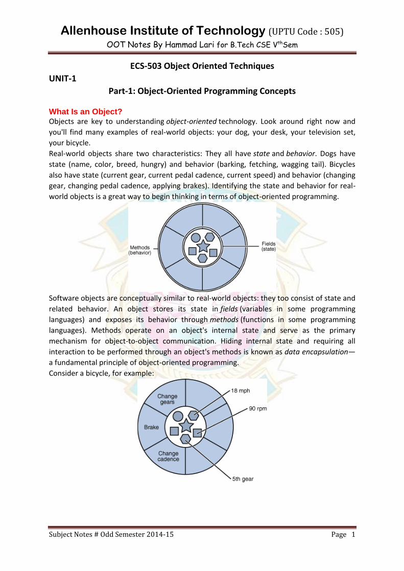
Software objects are conceptually similar to real-world objects: they too consist of state and
related behavior. An object stores its state in fields (variables in some programming
languages) and exposes its behavior through methods (functions in some programming
languages). Methods operate on an object's internal state and serve as the primary
mechanism for object-to-object communication. Hiding internal state and requiring all
interaction to be performed through an object's methods is known as data encapsulation—
a fundamental principle of object-oriented programming.
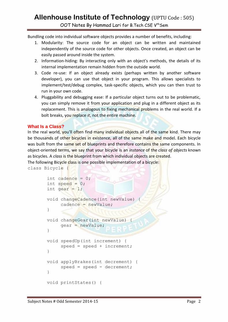
Consider a bicycle, for example:
Allenhouse Institute of Technology (UPTU Code : 505)
OOT Notes By Hammad Lari for B.Tech CSE VthSem
Subject Notes # Odd Semester 2014-15 Page 2
Bundling code into individual software objects provides a number of benefits, including:
1. Modularity: The source code for an object can be written and maintained
independently of the source code for other objects. Once created, an object can be
easily passed around inside the system.
2. Information-hiding: By interacting only with an object's methods, the details of its
internal implementation remain hidden from the outside world.
3. Code re-use: If an object already exists (perhaps written by another software
developer), you can use that object in your program. This allows specialists to
implement/test/debug complex, task-specific objects, which you can then trust to
run in your own code.
4. Pluggability and debugging ease: If a particular object turns out to be problematic,
you can simply remove it from your application and plug in a different object as its
replacement. This is analogous to fixing mechanical problems in the real world. If a
bolt breaks, you replace it, not the entire machine.
What Is a Class? In the real world, you'll often find many individual objects all of the same kind. There may
be thousands of other bicycles in existence, all of the same make and model. Each bicycle
was built from the same set of blueprints and therefore contains the same components. In
object-oriented terms, we say that your bicycle is an instance of the class of objects known
as bicycles. A class is the blueprint from which individual objects are created.
The following Bicycle class is one possible implementation of a bicycle: class Bicycle {
int cadence = 0;
int speed = 0;
int gear = 1;
void changeCadence(int newValue) {
cadence = newValue;
}
void changeGear(int newValue) {
gear = newValue;
}
void speedUp(int increment) {
speed = speed + increment;
}
void applyBrakes(int decrement) {
speed = speed - decrement;
}
void printStates() {
Allenhouse Institute of Technology (UPTU Code : 505)
OOT Notes By Hammad Lari for B.Tech CSE VthSem
Subject Notes # Odd Semester 2014-15 Page 3
System.out.println("cadence:"+cadence+"
speed:"+speed+" gear:"+gear);
}
}
You may have noticed that the Bicycle class does not contain a main method. That's because
it's not a complete application; it's just the blueprint for bicycles that might beused in an
application. The responsibility of creating and using new Bicycle objects belongs to some
other class in your application.
Here's a BicycleDemo class that creates two separate Bicycle objects and invokes their
methods: class BicycleDemo {
public static void main(String[] args) {
// Create two different Bicycle objects
Bicycle bike1 = new Bicycle();
Bicycle bike2 = new Bicycle();
// Invoke methods on those objects
bike1.changeCadence(50);
bike1.speedUp(10);
bike1.changeGear(2);
bike1.printStates();
bike2.changeCadence(50);
bike2.speedUp(10);
bike2.changeGear(2);
bike2.changeCadence(40);
bike2.speedUp(10);
bike2.changeGear(3);
bike2.printStates();
}
}
The output of this test prints the ending pedal cadence, speed, and gear for the two bicycles: cadence:50 speed:10 gear:2
cadence:40 speed:20 gear:3
What Is Inheritance? Different kinds of objects often have a certain amount in common with each other.
Mountain bikes, road bikes, and tandem bikes, for example, all share the characteristics of
bicycles (current speed, current pedal cadence, current gear). Yet each also defines
additional features that make them different: tandem bicycles have two seats and two sets
of handlebars; road bikes have drop handlebars; some mountain bikes have an additional
chain ring, giving them a lower gear ratio.
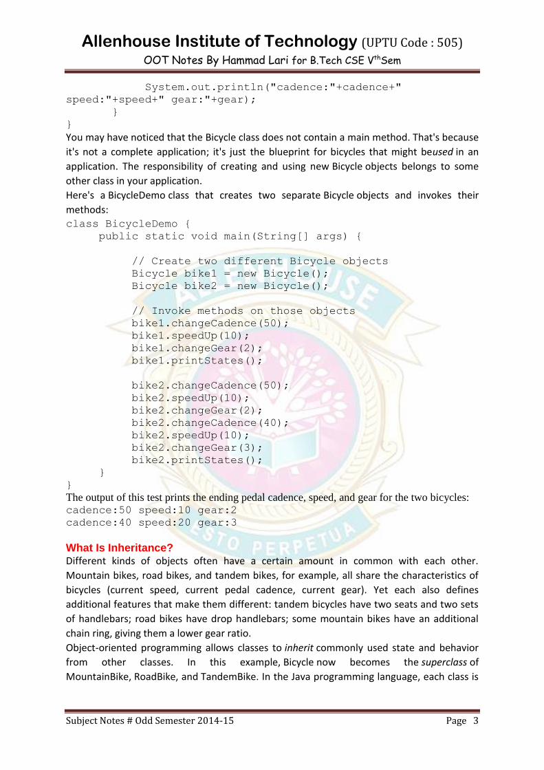
Object-oriented programming allows classes to inherit commonly used state and behavior
from other classes. In this example, Bicycle now becomes the superclass of
MountainBike, RoadBike, and TandemBike. In the Java programming language, each class is
Allenhouse Institute of Technology (UPTU Code : 505)
OOT Notes By Hammad Lari for B.Tech CSE VthSem
Subject Notes # Odd Semester 2014-15 Page 4
allowed to have one direct superclass, and each superclass has the potential for an
unlimited number of subclasses:
The syntax for creating a subclass is simple. At the beginning of your class declaration, use
the extends keyword, followed by the name of the class to inherit from:
class MountainBike extends Bicycle {
// new fields and methods defining a mountain bike would go here
}
What Is Abstraction? Abstraction is the essential element of Object Oriented programming (OOP). It refers to the
representation of essential features without including the background details or
explanations or implementations. This abstraction is achieved in java with interfaces.
What Is Encapsulation? The wrapping of data and functions into a single unit called class is known as encapsulation.
Accessing to the code and data inside the wrapper is tightly controlled through a well-
defined interface.
What Is Polymorphism? Polymorphism is another important OOP concept, Polymorphism means the ability to take
more than one form. By providing the interface mechanism, Java allows to fully utilize the
one interface, multiple methods aspect of polymorphism. For example, a dog's sense of
smell() is polymorphic which has many forms such as If the dog smells() a cat, it will bark and
run after it. If the dog smells() its food, it will salivate and run to its bowl. The same sense of
smell() in both situations doing different job depending on what is being smelled(), ie. the
type of data operated upon by the dog's nose. This polymorphism is achieved in java in 2
ways ie. by defining the interfaces or by overriding the methods in the subclass.

Allenhouse Institute of Technology (UPTU Code : 505)
OOT Notes By Hammad Lari for B.Tech CSE VthSem
Subject Notes # Odd Semester 2014-15 Page 5
Part-2: UML Concepts The UML is a graphical language for visualizing, specifying, constructing, and documenting
the artifacts of a software-intensive system. The UML gives you a standard way to write a
system's blueprints, covering conceptual things, such as business processes and system
functions, as well as concrete things, such as classes written in a specific programming
language, database schemas, and reusable software components.
Model
A model is a simplification of reality. A model provides the blueprints of a system. A model
may be structural, emphasizing the organization of the system, or it may be behavioral,
emphasizing the dynamics of the system.
Why do we model
We build models so that we can better understand the system we are developing.
Through modeling, we achieve four aims.
1. Models help us to visualize a system as it is or as we want it to be.
2. Models permit us to specify the structure or behavior of a system.
3. Models give us a template that guides us in constructing a system.
4. Models document the decisions we have made.
We build models of complex systems because we cannot comprehend such a system in its
entirety.
Principles of Modeling
There are four basic principles of model
1. The choice of what models to create has a profound influence on how a problem is
attacked and how a solution is shaped.
2. Every model may be expressed at different levels of precision.
3. The best models are connected to reality.
4. No single model is sufficient. Every nontrivial system is best approached through a
small set of nearly independent models.
Object Oriented Modeling
In software, there are several ways to approach a model. The two most common ways are
1. Algorithmic perspective
2. Object-oriented perspective
Algorithmic Perspective
The traditional view of software development takes an algorithmic perspective. In this
approach, the main building block of all software is the procedure or function. This view
leads developers to focus on issues of control and the decomposition of larger algorithms
into smaller ones. As requirements change and the system grows, systems built with an
algorithmic focus turn out to be very hard to maintain.
Object-oriented perspective
The contemporary view of software development takes an object-oriented perspective. In
this approach, the main building block of all software systems is the object or class. A class is
a description of a set of common objects. Every object has identity, state, and behavior.
Allenhouse Institute of Technology (UPTU Code : 505)
OOT Notes By Hammad Lari for B.Tech CSE VthSem
Subject Notes # Odd Semester 2014-15 Page 6
Object-oriented development provides the conceptual foundation for assembling systems
out of components using technology such as Java Beans or COM+.
An Overview of UML
The Unified Modeling Language is a standard language for writing software
blueprints. The UML may be used to visualize, specify, construct, and document the
artifacts of a software-intensive system.
The UML is appropriate for modeling systems ranging from enterprise information
systems to distributed Web-based applications and even to hard real time
embedded systems. It is a very expressive language, addressing all the views needed
to develop and then deploy such systems.
The UML is a language for
Visualizing
Specifying
Constructing
Documenting
Visualizing The UML is more than just a bunch of graphical symbols. Rather, behind each
symbol in the UML notation is a well-defined semantics. In this manner, one developer can
write a model in the UML, and another developer, or even another tool, can interpret that
model unambiguously
Specifying means building models that are precise, unambiguous, and complete.
Constructing the UML is not a visual programming language, but its models can be directly
connected to a variety of programming languages
Documenting a healthy software organization produces all sorts of artifacts in addition to
raw executable code. These artifacts include
1.Requirements 2.Architecture 3.Design
4.Source code 5.Project plans 6.Tests
7.Prototypes 8.Releases
Conceptual Model of UML
To understand the UML, you need to form a conceptual model of the language, and this
requires learning three major elements: the UML's basic building blocks, the rules that
dictate how those building blocks may be put together, and some common mechanisms
that apply throughout the UML.
Basic Building Block of UML
1. Things
2. Relationships
3. Diagrams
Things in the UML
There are four kinds of things in the UML:
1. Structural things
2. Behavioral things

Allenhouse Institute of Technology (UPTU Code : 505)
OOT Notes By Hammad Lari for B.Tech CSE VthSem
Subject Notes # Odd Semester 2014-15 Page 7
3. Grouping things
4. Annotational things
Structural things are the nouns of UML models. These are the mostly static parts of a
model, representing elements that are either conceptual or physical. In all, there are seven
kinds of structural things.
1. Classes
2. Interfaces
3. Collaborations
4. Use cases
5. Active classes
6. Components
7. Nodes
Class is a description of a set of objects that share the same attributes, operations,
relationships, and semantics. A class implements one or more interfaces. Graphically, a class
is rendered as a rectangle, usually including its name, attributes, and operations.
Interface
Interface is a collection of operations that specify a service of a class or component. An
interface therefore describes the externally visible behavior of that element. An interface
might represent the complete behavior of a class or component or only a part of that
behavior. An interface is rendered as a circle together with its name. An interface rarely
stands alone. Rather, it is typically attached to the class or component that realizes the
interface
Collaboration defines an interaction and is a society of roles and other elements that work
together to provide some cooperative behavior that's bigger than the sum of all the
elements. Therefore, collaborations have structural, as well as behavioral, dimensions. A
given class might participate in several collaborations.
Graphically, a collaboration is rendered as an ellipse with dashed lines, usually including only
its name
Usecase
Use case is a description of set of sequence of actions that a system performs that
yields an observable result of value to a particular actor
Use case is used to structure the behavioral things in a model.

Allenhouse Institute of Technology (UPTU Code : 505)
OOT Notes By Hammad Lari for B.Tech CSE VthSem
Subject Notes # Odd Semester 2014-15 Page 8
A use case is realized by a collaboration. Graphically, a use case is rendered as an
ellipse with solid lines, usually including only its name
Active class is just like a class except that its objects represent elements whose behavior is
concurrent with other elements. Graphically, an active class is rendered just like a class, but
with heavy lines, usually including its name, attributes, and operations
Component is a physical and replaceable part of a system that conforms to and provides the
realization of a set of interfaces. Graphically, a component is rendered as a rectangle with
tabs
Node is a physical element that exists at run time and represents a computational resource,
generally having at least some memory and, often, processing capability. Graphically, a node
is rendered as a cube, usually including only its name
Behavioral Things are the dynamic parts of UML models. These are the verbs of a model,
representing behavior over time and space. In all, there are two primary kinds of behavioral
things
1. Interaction
2. state machine
Interaction
Interaction is a behavior that comprises a set of messages exchanged among a set of objects
within a particular context to accomplish a specific purpose. An interaction involves a
number of other elements, including messages, action sequences and links. Graphically a
message is rendered as a directed line, almost always including the name of its operation
State Machine
State machine is a behavior that specifies the sequences of states an object or an interaction
goes through during its lifetime in response to events, together with its responses to those
events. State machine involves a number of other elements, including states, transitions,
events and activities. Graphically, a state is rendered as a rounded rectangle, usually
including its name and its substates

Allenhouse Institute of Technology (UPTU Code : 505)
OOT Notes By Hammad Lari for B.Tech CSE VthSem
Subject Notes # Odd Semester 2014-15 Page 9
Grouping Things:-
1. are the organizational parts of UML models. These are the boxes into which a model
can be decomposed
2. There is one primary kind of grouping thing, namely, packages.
Package:-
A package is a general-purpose mechanism for organizing elements into groups.
Structural things, behavioral things, and even other grouping things may be placed in a
package
Graphically, a package is rendered as a tabbed folder, usually including only its name
and, sometimes, its contents
Annotational things are the explanatory parts of UML models. These are the comments you
may apply to describe about any element in a model.
A note is simply a symbol for rendering constraints and comments attached to an element
or a collection of elements. Graphically, a note is rendered as a rectangle with a dog-eared
corner, together with a textual or graphical comment
Relationships in the UML: There are four kinds of relationships in the UML:
1. Dependency
2. Association
3. Generalization
4. Realization
Dependency:-
Dependency is a semantic relationship between two things in which a change to one
thing may affect the semantics of the other thing. Graphically a dependency is rendered as
a dashed line, possibly directed, and occasionally including a label
Association is a structural relationship that describes a set of links, a link being a connection
among objects. Graphically an association is rendered as a solid line, possibly directed,
occasionally including a label, and often containing other adornments, such as multiplicity
and role names
Aggregation is a special kind of association, representing a structural relationship between a
whole and its parts. Graphically, a generalization relationship is rendered as a solid line with
a hollow arrowhead pointing to the parent
Allenhouse Institute of Technology (UPTU Code : 505)
OOT Notes By Hammad Lari for B.Tech CSE VthSem
Subject Notes # Odd Semester 2014-15 Page 10
Realization is a semantic relationship between classifiers, wherein one classifier specifies a
contract that another classifier guarantees to carry out. Graphically a realization relationship
is rendered as a cross between a generalization and a dependency relationship
Diagrams in the UML
Diagram is the graphical presentation of a set of elements, most often rendered as a
connected graph of vertices (things) and arcs (relationships). In theory, a diagram may
contain any combination of things and relationships.
For this reason, the UML includes nine such diagrams:
1. Class diagram
2. Object diagram
3. Use case diagram
4. Sequence diagram
5. Collaboration diagram
6. Statechart diagram
7. Activity diagram
8. Component diagram
9. Deployment diagram
Class diagram
A class diagram shows a set of classes, interfaces, and collaborations and their relationships.
Class diagrams that include active classes address the static process view of a system.
Object diagram
Object diagrams represent static snapshots of instances of the things found in class
diagrams. These diagrams address the static design view or static process view of a system.
An object diagram shows a set of objects and their relationships
Use case diagram
A use case diagram shows a set of use cases and actors and their relationships. Use case
diagrams address the static use case view of a system. These diagrams are especially
important in organizing and modeling the behaviors of a system.
Interaction Diagrams
Both sequence diagrams and collaboration diagrams are kinds of interaction diagrams.
Interaction diagrams address the dynamic view of a system
A sequence diagram is an interaction diagram that emphasizes the time-ordering of
messages
A collaboration diagram is an interaction diagram that emphasizes the structural
organization of the objects that send and receive messages
Sequence diagrams and collaboration diagrams are isomorphic, meaning that you
can take one and transform it into the other
Statechart diagram
A statechart diagram shows a state machine, consisting of states, transitions, events, and
activities. Statechart diagrams address the dynamic view of a system. They are especially

Allenhouse Institute of Technology (UPTU Code : 505)
OOT Notes By Hammad Lari for B.Tech CSE VthSem
Subject Notes # Odd Semester 2014-15 Page 11
important in modeling the behavior of an interface, class, or collaboration and emphasize
the event-ordered behavior of an object
Activity diagram
An activity diagram is a special kind of a statechart diagram that shows the flow from
activity to activity within a system. Activity diagrams address the dynamic view of a system.
They are especially important in modeling the function of a system and emphasize the flow
of control among objects
Component diagram
A component diagram shows the organizations and dependencies among a set of
components. Component diagrams address the static implementation view of a
system.They are related to class diagrams in that a component typically maps to one or
more classes, interfaces, or collaborations
Deployment diagram
A deployment diagram shows the configuration of run-time processing nodes and the
components that live on them. Deployment diagrams address the static deployment view of
an architecture
Rules of the UML
The UML has semantic rules for
1. Names What you can call things, relationships, and diagrams
2. Scope The context that gives specific meaning to a name
3. Visibility How those names can be seen and used by others
4. Integrity How things properly and consistently relate to one another
5. Execution What it means to run or simulate a dynamic model
Models built during the development of a software-intensive system tend to evolve and
may be viewed by many stakeholders in different ways and at different times. For this
reason, it is common for the development team to not only build models that are well-
formed, but also to build models that are
1. Elided Certain elements are hidden to simplify the view
2. Incomplete Certain elements may be missing
3. Inconsistent The integrity of the model is not guaranteed
Common Mechanisms in the UML
UML is made simpler by the presence of four common mechanisms that apply consistently
throughout the language.
1. Specifications
2. Adornments
3. Common divisions
4. Extensibility mechanisms
Specification that provides a textual statement of the syntax and semantics of that building
block. The UML's specifications provide a semantic backplane that contains all the parts of
all the models of a system, each part related to one another in a consistent fashion

Allenhouse Institute of Technology (UPTU Code : 505)
OOT Notes By Hammad Lari for B.Tech CSE VthSem
Subject Notes # Odd Semester 2014-15 Page 12
Adornments Most elements in the UML have a unique and direct graphical notation that
provides a visual representation of the most important aspects of the element. A class's
specification may include other details, such as whether it is abstract or the visibility of its
attributes and operations. Many of these details can be rendered as graphical or textual
adornments to the class's basic rectangular notation.
Extensibility Mechanisms
The UML's extensibility mechanisms include
1. Stereotypes
2. Tagged values
3. Constraints
Stereotype
Stereotype extends the vocabulary of the UML, allowing you to create new kinds of
building blocks that are derived from existing ones but that are specific to your problem
A tagged value extends the properties of a UML building block, allowing you to create
new information in that element's specification
A constraint extends the semantics of a UML building block, allowing you to add new
rules or modify existing ones
Architecture
A system's architecture is perhaps the most important artifact that can be used to manage
these different viewpoints and so control the iterative and incremental development of a
system throughout its life cycle.
Architecture is the set of significant decisions about
1. The organization of a software system
2. The selection of the structural elements and their interfaces by which the system is
composed
3. Their behavior, as specified in the collaborations among those elements
4. The composition of these structural and behavioral elements into progressively
larger subsystems
The architectural style that guides this organization: the static and dynamic elements
and their interfaces, their collaborations, and their composition.
Software architecture is not only concerned with structure and behavior, but also with
usage, functionality, performance, resilience, reuse, comprehensibility, economic and
technology constraints and trade-offs, and aesthetic concerns.
Use case view
The use case view of a system encompasses the use cases that describe the behavior of
the system as seen by its end users, analysts, and testers.
With the UML, the static aspects of this view are captured in use case diagrams
The dynamic aspects of this view are captured in interaction diagrams, state chart
diagrams, and activity diagrams.

Allenhouse Institute of Technology (UPTU Code : 505)
OOT Notes By Hammad Lari for B.Tech CSE VthSem
Subject Notes # Odd Semester 2014-15 Page 13
Design View
The design view of a system encompasses the classes, interfaces, and collaborations that
form the vocabulary of the problem and its solution.
This view primarily supports the functional requirements of the system, meaning the
services that the system should provide to its end users.
Process View
The process view of a system encompasses the threads and processes that form the
system's concurrency and synchronization mechanisms.
This view primarily addresses the performance, scalability, and throughput of the system
Implementation View
The implementation view of a system encompasses the components and files that
are used to assemble and release the physical system.
This view primarily addresses the configuration management of the system's
releases, made up of somewhat independent components and files that can be assembled
in various ways to produce a running system.
Deployment View
The deployment view of a system encompasses the nodes that form the system's
hardware topology on which the system executes.
This view primarily addresses the distribution, delivery, and installation of the parts that
make up the physical system.