alloy 690 steam generator tubes - trueflaw.com · alloy 690 steam generator tubes 3.1 crack...
TRANSCRIPT

1
TRUEFLAW LTD. | TILLINMÄENTIE 3 TILA A113, FI-02330 ESPOO, FINLAND | [email protected] | TEL. +358 45 635 4415, +358 45 635 4414
ALLOY 690 STEAM GENERATOR TUBES
3.1 CRACK PRODUCTION IN INCONEL 690 STEAM GENERATOR TUBES
Inconel 690 steam generator tubes are used in the modern EPRTM reactor type that is currently under construction in Olkiluoto (later “OL3”), Finland. This material has been selected due to its high resistance to stress corrosion cracking that has caused problems in older reactor types (made from stainless steel or Inconel 600). According to Finnish regulations, all in-service inspections to be performed to the new power plant must be qualified. In qualification, the performance of the inspection technique to be applied is shown on realistic defects. Hence, also the SG-tubes were qualified according to Finnish regulations.
The qualification done for OL-3 was the first to be completed on Inconel 690 tubes with real cracks. Consequently, no cracked specimens were available nor had such specimens ever had been manufactured. Areva NP approached Trueflaw to manufacture the cracked samples. Figure 1. shows drawing of the tube sample used in qualification.
Originally published in: 6th CNS International Steam generator conference, November 2009
Figure 1 Tube sample drawing. The material is Inconel 690.
3.1.1 Development and validation of crack production to Inconel 690 steam generator tubes
Crack production to Inconel 690 steam generator tubes posed several challenges. Firstly, due to the thin wall section and correspondingly small crack depth targets, the tolerances for crack production were set very tight.
Hence, the first target was to obtain successful small crack initiation to this new material with the thin wall section. After several trials, successful circumferential cracking was obtained (Figure 2). However, rather unexpected difficulties were met when developing technique for axial cracking. As it turned out, the material was highly anisotropic with respect to cracking. Presumably this is caused by the microstructural texture resulting from tube manufacturing. It was noticed, that the samples strongly

2
TRUEFLAW LTD. | TILLINMÄENTIE 3 TILA A113, FI-02330 ESPOO, FINLAND | [email protected] | TEL. +358 45 635 4415, +358 45 635 4414
preferred circumferential cracking over axial cracking. Consequently, no axial cracking could be produced without accompanying circumferential cracking.
Figure 2 Small crack initiation in Alloy 690 steam generator tube; a dye penetrant indication.
The specified cracking included long and shallow cracks, i.e. the cracking extended up to several millimeters around the circumference but only a fraction of a millimeter in depth direction. Consequently, the production was met with a problem of through wall cracking. That is, successful crack initiation was obtained, but as soon as the surface length of the crack was extended, cracks rapidly grew through-wall. To overcome this problem, it was decided to produce the desired dimensions with non-contiguous cracking. Figure 3 shows such a non-contiguous crack pattern produced.
Figure 3 Circumferential cracking in steam generator tube samples.

3
TRUEFLAW LTD. | TILLINMÄENTIE 3 TILA A113, FI-02330 ESPOO, FINLAND | [email protected] | TEL. +358 45 635 4415, +358 45 635 4414
The validation samples were then sent to Intercontrole for inspection (see paragraph 3.1.2). The purpose of these inspections was to confirm that the produced samples are suitable for the intended use and to give the inspectors early experience on the cracked samples. Finally, the validation samples were destructively examined by Trueflaw in order to confirm the depth of the cracks.
Figure 4shows an image of destructive examination of a validation sample.
3.1.2 Inspection results
Three samples were inspected with eddy current inspection by Intercontrole. The samples are detailed in Table 1. Inspection was carried out with two different probes: bobbin probe and rotating probe (Figure 5).
Table 1 Samples in eddy current inspection. All cracks were circumferential. The depth values for samples 1 and 2 are measured from destructive examination of sample 1. Other values are directly measured on the sample.
# Cracks Note1 OD crack, 20% depth, 100° angular extension destructively examined
2 OD crack, 20% depth, 140° angular extension
3 through-wall crack, 48° angular extension
Figure 5 The probes used in the inspection were ET Bobbin probe, Zetec 610UL (upper image) and ET rotating probe, Zetec 3 coil 610PP with 1 +point coil PP11A, 1 pancake coil 115MR Ø 3 mm (medium range) and 1 pancake coil 080 HF Ø 2 mm (High frequency) (lower image).

4
TRUEFLAW LTD. | TILLINMÄENTIE 3 TILA A113, FI-02330 ESPOO, FINLAND | [email protected] | TEL. +358 45 635 4415, +358 45 635 4414
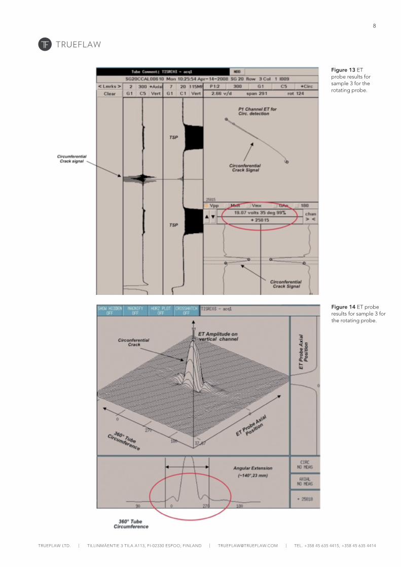
The EC response of cracks in each sample with two different probes can be seen in Figures 6-14. Three different pictures are shown for each sample: first the result of bobbin probe then results of rotating probe signals and finally topographic picture of the rotating probe response. The crack signal is marked to each image. The ET bobbin probe clearly detects single indication for all the inspected samples. For samples 1 and 2 the indication is correctly interpreted as OD defect and for sample 3 the indication is correctly interpreted as through-wall defect.
The results for the rotating probe are summarized in Table 2. The sizing results from the rotating probe agree very well with the true crack sizes. For the sample 1, where direct destructive results are available, the depth sizing is within 5%-units of the true depth, which corresponds to about 0.05 mm. For the sample 2, which was produced similarly to sample 1, the inspection results are within expected crack depth variance ±0.3 mm. Furthermore, the EC inspection indicated that the thermal loading had caused slight local denting of the tube. However, this did not disturb the inspection.
Table 2 Results for the rotating probe inspection.
Sample Amplitude (V) Phase (OD plane, °)
Depth (%) Angular extension (°)
1 0,17 87 15 115
2 0,26 79 45 140
3 19,07 35 100 140
Figure 6 ET probe results for sample 1 for the bobbin probe.

5
TRUEFLAW LTD. | TILLINMÄENTIE 3 TILA A113, FI-02330 ESPOO, FINLAND | [email protected] | TEL. +358 45 635 4415, +358 45 635 4414
Figure 7 ET probe results for sample 1 for the rotating probe.
Figure 8 ET probe results for sample 1 for the rotating probe.

6
TRUEFLAW LTD. | TILLINMÄENTIE 3 TILA A113, FI-02330 ESPOO, FINLAND | [email protected] | TEL. +358 45 635 4415, +358 45 635 4414
Figure 9 ET probe results for sample 2 for the bobbin probe.
Figure 10 ET probe results for sample 2 for the rotating probe.

7
TRUEFLAW LTD. | TILLINMÄENTIE 3 TILA A113, FI-02330 ESPOO, FINLAND | [email protected] | TEL. +358 45 635 4415, +358 45 635 4414
SABON + VERLAG
Figure 11 ET probe results for sample 2 for the rotating probe.
Figure 12 ET probe results for sample 3 for the bobbin probe.
8
TRUEFLAW LTD. | TILLINMÄENTIE 3 TILA A113, FI-02330 ESPOO, FINLAND | [email protected] | TEL. +358 45 635 4415, +358 45 635 4414
SABON + VERLAG
Figure 13 ET probe results for sample 3 for the rotating probe.
Figure 14 ET probe results for sample 3 for the rotating probe.

9
TRUEFLAW LTD. | TILLINMÄENTIE 3 TILA A113, FI-02330 ESPOO, FINLAND | [email protected] | TEL. +358 45 635 4415, +358 45 635 4414
3.1.3 Conclusions
Cracks were successfully produced to Inconel 690 samples in circumferential direction. Samples strongly preferred circumferential crack growth over axial crack growth. The cracked samples showed that the specified crack sizes can be reliably detected and characterized with the used probe design, even with the complex non-contiguous cracking morphology. The inspection method was successfully qualified for OL3.