allycad 2011 user guide
TRANSCRIPT

User Guide
Copyright 2010
Knowledge Base Software (Pty) Ltd

Conditions of Sale The purchaser (further referred to as the Licensee) hereby accepts a non-exclusive,
non-transferable license to use the software, AllyCAD, on the following conditions.
1. The license fee shall be payable in advance and this agreement commences on
said date of purchase.
2. A separate license fee is payable for each computer upon which the Licensee
wishes to have simultaneous use of the software.
3. It is the Licensee’s responsibility to insure the program for the full current
replacement value. In the event of theft or loss of the program, security disk
or security module, or damage to any of the foregoing, the license must be re-
purchased in full.
4. The Licensee undertakes not to copy, except for backup purposes, reproduce,
translate, adapt, vary or modify the software, nor to communicate the
software to any third party other than the Licensee’s employees, without the
Licensor’s prior written consent. The Licensee also undertakes not to bypass or
attempt to bypass the security measures incorporated in and supplied with
the program by any means whatsoever, including third-party applications
purporting to be a back-up system for hardware security devices.
5. The Licensee agrees that it shall not itself - nor through any subsidiary, agent
or third party - sell, lease, license, sub-license or otherwise deal with the
software.
6. The Licensee acknowledges that any and all of the intellectual property rights
including trademark, trade name, copyright and other rights used or
embodied in or in association with the software remain the sole property of
the Licensor and its principals.
7. The Licensee shall not question or dispute the ownership of any such rights at
any time.
8. No warranty of any kind is expressed or implied with regard to the use or
application of the software or it’s fitness for any particular purpose. The
verification of all results and output is entirely the responsibility of the
purchaser.
9. While every care has been taken in the preparation of the AllyCAD program
and it’s manual, Knowledge Base Software (Pty) Ltd, it’s employees and agents
shall not be liable for any loss or damage (including in particular,
consequential losses, loss of profits and penalties) suffered by the Licensee
arising from any cause whatsoever in connection with the AllyCAD program or
the use thereof whether such loss or damage results from breach of contract
(including a fundamental breach), negligence or any other cause and whether
or not this contract is at any time cancelled by the Licensee.
Table of Contents
INTRODUCTION 1-1 Where do I go from here? 1-1 Typefaces in this manual 1-1 How to get support 1-2
Online Help 1-2 Online Documentation 1-2
INSTALLATION AND STARTUP 2-1 What you need to know 2-1
System Requirements 2-1 Reading the README file 2-1
Installation 2-2 What is installed 2-2 Program Folder 2-2 Document Folders 2-2 Starting AllyCAD from Windows 2-3 Security 2-3 Safety Precautions 2-4 What to do now 2-4 Things You Should Know 2-4 Customizing AllyCAD 2-5
Conventions used in this manual 2-6
SCREEN, MOUSE AND KEYBOARD 3-1 Screen Layout 3-2
Prompt Area and Control Bar 3-6 Pen Selection 3-10 Line Style Display 3-11 Layer Display 3-11
Toolbars 3-12 Keyboard and Mouse 3-13
Keyboard 3-13 Mouse 3-18
ACCURATE DRAWING 4-1 Move an exact distance up, down, left, or right 4-2 Move an exact distance in a specific direction 4-3 Lock cursor to an exact angle (ortho mode) 4-4 Move to an exact coordinate location on the screen 4-5 Move exactly onto an existing part of the drawing 4-6
Jumps 4-7 Snap Modes 4-8

Drawing with a grid 4-9
GEOMETRY 5-1 Geometry elements 5-2
Properties of geometry 5-2 Using geometry as guidelines to trace over 5-3 Projecting solid lines and arcs to geometry lines and circles 5-4 Jumping to geometry lines, arcs and intersections 5-4
Snapping to geometry lines, arcs and intersections 5-4 Switching geometry on and off 5-7
Deleting geometry 5-7
TUTORIAL 1 - THE SCREEN 6-1 Important notes to read before you start 6-2
Open an existing drawing 6-3 Redraw to the paper extents 6-5
Magnifying and de-magnifying 6-6 Using the mouse wheel 6-6 Using the keyboard 6-6
Panning 6-8 Pan 6-8 Long Pan 6-9
Zooming 6-11 Splitting the screen into different views 6-13
Setting up views 6-13 Splitting the view horizontally 6-15 Joining views 6-15
Finally 6-16
TUTORIAL 2 - VIEWPORTS AND LAYOUTS 7-1 Drawing Space 7-2 Viewports 7-4 Layouts 7-7
TUTORIAL 3 - 3D DRAWING AND SOLID FORM 8-1 Viewing planes 8-2 Drawing Planes 8-4 3D Drawing 8-5 Adding Layers 8-6
Drawing the Mallet Head 8-6 View Directions 8-8 DP Elevation 8-8 Drawing Plane Snap 8-9 Defining the Drawing Plane using 3 Points 8-10 Setting Drawing Plane indicator position 8-11

Add Solid form to the Drawing using 3D Face 8-13 Drawing Plane Offset 8-14 Drawing the Mallet Handle 8-17 Add Solid form to the Drawing using 3D Face 8-20
APPENDIX A - TOOLBAR ICONS 9-1 Applications Toolbar 9-1 Dimensions Toolbar 9-2 Draw Toolbar 9-3 Drawing Plane Toolbar 9-5 Geometry Toolbar 9-6 Insert Toolbar 9-7 Jumps Toolbar 9-8 Lock Cursor Toolbar 9-9 Main Toolbar 9-9 Misc Toolbar 9-12 Modify Toolbar 9-13 Pens Toolbar 9-14 Scripts Toolbar 9-15 Settings Toolbar 9-15 Snaps Toolbar 9-17 Tools Toolbar 9-18 View Axis Toolbar 9-20 Zooms Toolbar 9-21 Screen Toolbar 9-22 Toolkit Toolbars 9-24

Introduction 1-1
Introduction
This manual will help you install AllyCAD 2010 and get started. It also includes easy-
to-follow tutorials for hands-on experience with the program.
Where do I go from here?
After reading this manual you should know the following:
• how to get AllyCAD up and running
• use the menus and the on-line help system
• how to draw accurately
• how to use geometry (construction) lines
• how to start a 3D drawing
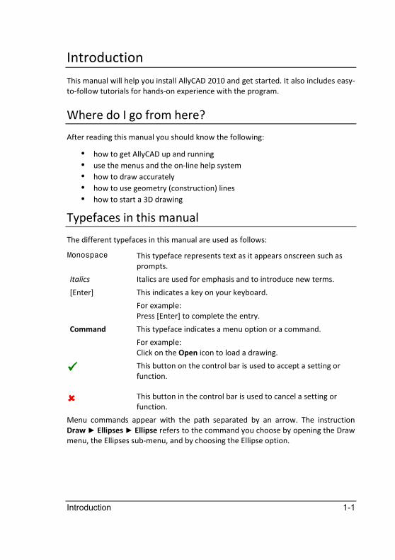
Typefaces in this manual
The different typefaces in this manual are used as follows:
Monospace This typeface represents text as it appears onscreen such as
prompts.
Italics Italics are used for emphasis and to introduce new terms.
[Enter] This indicates a key on your keyboard.
For example:
Press [Enter] to complete the entry.
Command This typeface indicates a menu option or a command.
For example:
Click on the Open icon to load a drawing.
����
This button on the control bar is used to accept a setting or
function.
���� This button in the control bar is used to cancel a setting or
function.
Menu commands appear with the path separated by an arrow. The instruction
Draw ► Ellipses ► Ellipse refers to the command you choose by opening the Draw
menu, the Ellipses sub-menu, and by choosing the Ellipse option.

1-2 AllyCAD 2010
How to get support
Technical support is available from 08.00 to 17.00 (CAT/GMT+2) Mondays to
Fridays excluding public holidays.
South Africa 086 0101 999
International +27 21 7011850
You can also email your support enquiries to our Customer Support Centre at
Online Help
While using the program you can press F1 for context sensitive help at any time.
The help items can be printed if required using the Windows Help system.
Online Documentation
The User Guide is also supplied on the CD-ROM in Adobe Acrobat PDF format. This
allows you to browse through the manual, to search for specific subjects, and to
print out all or any selection of pages.
Installation and Startup 2-1
Installation and Startup
Before you begin working:
• check the contents of your package
• make sure that your hardware satisfies the requirements
• run the installation program
• plug the security module into your USB port
• start AllyCAD.
What you need to know
This manual assumes that you are familiar with basic Windows operations. If you
are not, you should read the documentation that came with your copy of Windows
before installing and using the program.
System Requirements
Before you install AllyCAD, ensure that your hardware and system software meets
the following requirements:
• 2.2MHz Core Duo or better
• 2GB or more RAM (4GB or more recommended)
• 200Mb or more free hard disk space
• Microsoft Windows XP/Vista or later.
• A screen sub-system configured to a resolution of at least 1024 x 800.
• CD-ROM drive
All printers, plotters, screens, and mice are supported via Windows. If Windows
does not include a driver for your particular printer or plotter, please contact your
printer or plotter manufacturer. They should be able to provide you with a
Windows driver for your device.
Reading the README file
Any last-minute changes or additions to AllyCAD are documented in the
README.TXT file. When the Setup program has finished installing AllyCAD on your
hard disk it displays the README file. You can view the README file using Windows
WordPad and print the contents at any stage.
2-2 AllyCAD 2010
Installation
1. Insert the program CD into the CD-ROM drive.
2. If the installation program does not start automatically and you are using
Windows XP/Vista or later, click on Start ► Run to run the SETUP program on
the CD.
3. Follow the prompts of the AllyCAD installation program. AllyCAD will be
installed in the folder that you choose.
What is installed
The Setup program creates a number of folders and also modifies the Windows
Registry. These changes are explained in the following sections.
Program Folder
The folder that AllyCAD is installed into is called your Program Home folder. Unless
you specified another name when you installed AllyCAD, your Program Home
folder is called AllyCAD 2010 and is installed as a sub-folder of Program
Files\Knowledge Base Software. It also contains the Manuals sub-folder where the
on-line version of the printed documentation is stored.
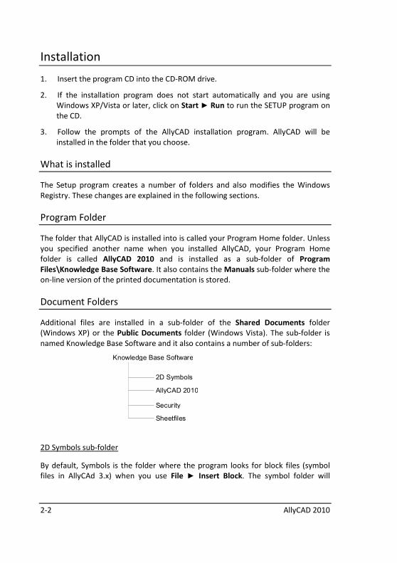
Document Folders
Additional files are installed in a sub-folder of the Shared Documents folder
(Windows XP) or the Public Documents folder (Windows Vista). The sub-folder is
named Knowledge Base Software and it also contains a number of sub-folders:
Knowledge Base Software
2D Symbols
AllyCAD 2010
Security
Sheetfiles
2D Symbols sub-folder
By default, Symbols is the folder where the program looks for block files (symbol
files in AllyCAd 3.x) when you use File ► Insert Block. The symbol folder will
Installation and Startup 2-3
contain some sample block files as well as symbol files for you to use when you are
working with the Architectural toolkit.
AllyCAD 2010 sub-folder
This folder contains the menu, toolbar and styles files.
Security sub-folder
This folder contains files related to disk-based security and should under no
circumstances be altered or deleted.
Sheetfiles
The Sheetfiles sub-folder contains basic sheet layouts which include the title block
layout.
Starting AllyCAD from Windows
Once installation is complete, you can run the CAD by clicking on:
Start ► Programs ► AllyCAD 2010 ►AllyCAD 2010
To exit from inside AllyCAD, select File ► Exit.
Security
Before you can use the CAD you must call for an authorization code as follows:
1. Start the program.
2. Ensure that the security module is plugged into your USB port.
3. Select the File ► Security ► Authorize option.
4. A dialog box with your program code will be displayed. Contact your support
centre for your return code or click on the Save button and email the support
centre with the contents of the AUTHORISATION.TXT file.
5. Input the return code and press the [Authorize] button.
You are now ready to go. For more details refer to Security in the online help.
2-4 AllyCAD 2010
Safety Precautions
Please insure your program for the full replacement value. Should your security
module be lost or stolen you will have to purchase a new license.
What to do now
While the CAD is easy to use even without a manual, you will get up and running
more quickly if you read the following chapters:
• Screen, Mouse and Keyboard
• Accurate Drawing
• Geometry
• Shortcuts
Once you begin working on your own drawings you can consult the relevant
chapters of the help file for explanations of individual commands, and as you gain
confidence you can start customising the CAD to your own requirements.
Many CAD functions have short cuts associated with them. In order to get the best
out of the CAD we strongly recommend that you learn these. You can also define
your own short cuts using the Accelerator Editor.
Things You Should Know
If you read nothing else you should read the following chapters as they contain
information that is vital for producing accurate drawings quickly.
Screen, Mouse and Keyboard is an introduction to the CAD screen and the terms
used to describe its components.
Accurate Drawing lists methods of absolute, relative and polar cursor movement.
Geometry explains how to set up construction lines.
Installation and Startup 2-5
Customizing AllyCAD
Once you have enough confidence, you can customise AllyCAD to suit your own
requirements.
You can delete functions that you don't use using the Menu Editor, and add your
own functions using AllyCAD's scripting language.
You can totally re-arrange the menu system, and replace the functions on the icons
in the toolbar with the functions you use most often. You can also select certain
icons to sit on the various toolbars.
The following tools allow you to customise AllyCAD:
• Accelerator Editor
Customise the shortcut keys.
• Linestyle Editor
Create and edit your own line types.
• Menu Editor
Customise AllyCAD's menus.
• Palette Editor
Create and edit your own pen colours.
• Toolbar Editor
Customise AllyCAD's toolbars.
• Scripting
AllyCAD's scripting language allows you to develop new functions or
automate a series of existing functions. Refer to the on-line help for further
detail.
2-6 AllyCAD 2010
Conventions used in this manual
The following conventions are used in the manual.
Menus and Functions
All the functions in AllyCAD are described in detail in Chapters 1 - 10 of the online
Reference Manual. (Remember however that the menus are completely
customisable).
These are often accessible via various routes - by clicking on the functions in the
menu, via the keyboard (a short-cut key), and also by clicking on the respective icon
for that function.
Mouse
In this manual, clicking refers to pressing and releasing your left mouse button
quickly unless otherwise specified. When a click with your right mouse button is
required, the terms right click or right clicking are used.
Diagrams
All diagrams are shown with the cursor in Freehand mode except where AllyCAD
automatically uses one of the snap modes.
Screen, Mouse and Keyboard 3-1
Screen, Mouse and Keyboard
This section describes the various components that make up the CAD screen. These
are the:
• Title Bar
• Menu Bar
• Prompt Area and Control Bar
• Line Type Display
• Layer Display
• Toolbars
• Drawing Area
• Smart Cursor Help
• Coordinate Display
• Mouse
• Keyboard

3-2 AllyCAD 2010
Screen Layout
The CAD screen is divided into several parts, as shown below. Note that your layout
will not necessarily look like this as we have enabled a number of optional items in
order to pack the maximum amount of information into the image.
Specific areas of importance are explained below:.
A Menu
Access the various program functions by selecting menu items.
B Pen, Layer, Linetype, Width and Height
These are buttons, combo boxes and edit fields where you can change
drawing settings on the fly.
C Prompt/Bar Area
This area displays prompts while working or, for more complicated
procedures, displays a combination bar consisting of its own prompt area
and various buttons, etc. for making settings while working. An example of
such a bar is shown below:
Screen, Mouse and Keyboard 3-3
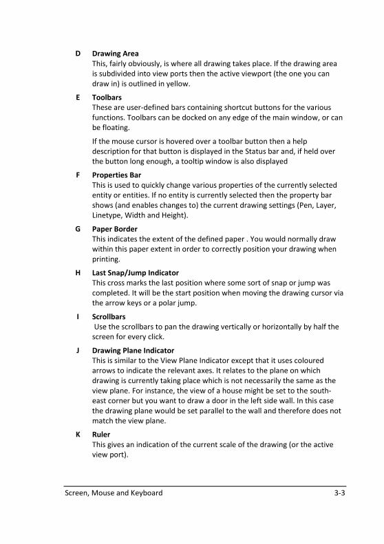
D Drawing Area
This, fairly obviously, is where all drawing takes place. If the drawing area
is subdivided into view ports then the active viewport (the one you can
draw in) is outlined in yellow.
E Toolbars
These are user-defined bars containing shortcut buttons for the various
functions. Toolbars can be docked on any edge of the main window, or can
be floating.
If the mouse cursor is hovered over a toolbar button then a help
description for that button is displayed in the Status bar and, if held over
the button long enough, a tooltip window is also displayed
F Properties Bar
This is used to quickly change various properties of the currently selected
entity or entities. If no entity is currently selected then the property bar
shows (and enables changes to) the current drawing settings (Pen, Layer,
Linetype, Width and Height).
G Paper Border
This indicates the extent of the defined paper . You would normally draw
within this paper extent in order to correctly position your drawing when
printing.
H Last Snap/Jump Indicator
This cross marks the last position where some sort of snap or jump was
completed. It will be the start position when moving the drawing cursor via
the arrow keys or a polar jump.
I Scrollbars
Use the scrollbars to pan the drawing vertically or horizontally by half the
screen for every click.
J Drawing Plane Indicator
This is similar to the View Plane Indicator except that it uses coloured
arrows to indicate the relevant axes. It relates to the plane on which
drawing is currently taking place which is not necessarily the same as the
view plane. For instance, the view of a house might be set to the south-
east corner but you want to draw a door in the left side wall. In this case
the drawing plane would be set parallel to the wall and therefore does not
match the view plane.
K Ruler
This gives an indication of the current scale of the drawing (or the active
view port).
3-4 AllyCAD 2010
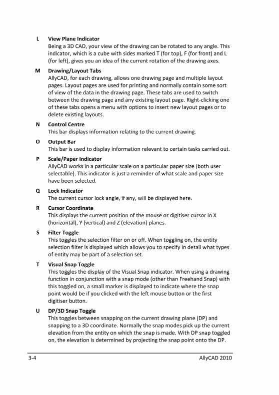
L View Plane Indicator
Being a 3D CAD, your view of the drawing can be rotated to any angle. This
indicator, which is a cube with sides marked T (for top), F (for front) and L
(for left), gives you an idea of the current rotation of the drawing axes.
M Drawing/Layout Tabs
AllyCAD, for each drawing, allows one drawing page and multiple layout
pages. Layout pages are used for printing and normally contain some sort
of view of the data in the drawing page. These tabs are used to switch
between the drawing page and any existing layout page. Right-clicking one
of these tabs opens a menu with options to insert new layout pages or to
delete existing layouts.
N Control Centre
This bar displays information relating to the current drawing.
O Output Bar
This bar is used to display information relevant to certain tasks carried out.
P Scale/Paper Indicator
AllyCAD works in a particular scale on a particular paper size (both user
selectable). This indicator is just a reminder of what scale and paper size
have been selected.
Q Lock Indicator
The current cursor lock angle, if any, will be displayed here.
R Cursor Coordinate
This displays the current position of the mouse or digitiser cursor in X
(horizontal), Y (vertical) and Z (elevation) planes.
S Filter Toggle
This toggles the selection filter on or off. When toggling on, the entity
selection filter is displayed which allows you to specify in detail what types
of entity may be part of a selection set.
T Visual Snap Toggle
This toggles the display of the Visual Snap indicator. When using a drawing
function in conjunction with a snap mode (other than Freehand Snap) with
this toggled on, a small marker is displayed to indicate where the snap
point would be if you clicked with the left mouse button or the first
digitiser button.
U DP/3D Snap Toggle
This toggles between snapping on the current drawing plane (DP) and
snapping to a 3D coordinate. Normally the snap modes pick up the current
elevation from the entity on which the snap is made. With DP snap toggled
on, the elevation is determined by projecting the snap point onto the DP.

Screen, Mouse and Keyboard 3-5
V DP/World Coordinate Toggle
This toggles the Cursor Coordinate between displaying coordinates relative
to the current drawing plane and true 3D coordinates.
W Keyboard Indicators
Shows whether Caps Lock and Num Lock are on or not.
3-6 AllyCAD 2010
Prompt Area and Control Bar
Prompts will be displayed in the prompt area asking for input or telling you what to
do. You type information, answer questions or select options in the Control Bar.
There are several types of prompts and responses.
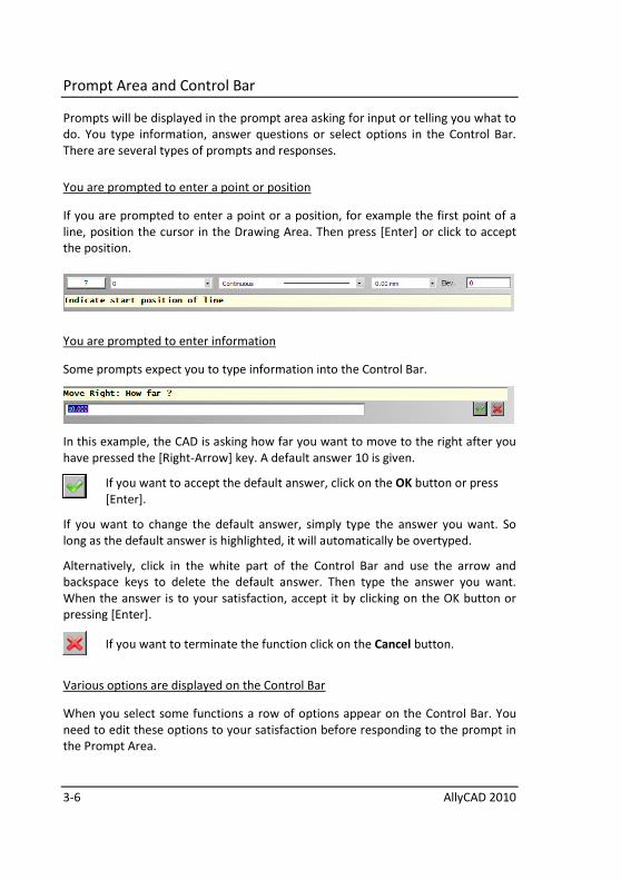
You are prompted to enter a point or position
If you are prompted to enter a point or a position, for example the first point of a
line, position the cursor in the Drawing Area. Then press [Enter] or click to accept
the position.
You are prompted to enter information
Some prompts expect you to type information into the Control Bar.
In this example, the CAD is asking how far you want to move to the right after you
have pressed the [Right-Arrow] key. A default answer 10 is given.
If you want to accept the default answer, click on the OK button or press
[Enter].
If you want to change the default answer, simply type the answer you want. So
long as the default answer is highlighted, it will automatically be overtyped.
Alternatively, click in the white part of the Control Bar and use the arrow and
backspace keys to delete the default answer. Then type the answer you want.
When the answer is to your satisfaction, accept it by clicking on the OK button or
pressing [Enter].
If you want to terminate the function click on the Cancel button.
Various options are displayed on the Control Bar
When you select some functions a row of options appear on the Control Bar. You
need to edit these options to your satisfaction before responding to the prompt in
the Prompt Area.
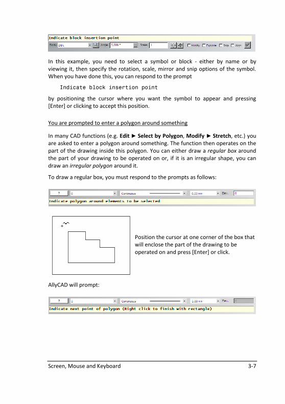
Screen, Mouse and Keyboard 3-7
In this example, you need to select a symbol or block - either by name or by
viewing it, then specify the rotation, scale, mirror and snip options of the symbol.
When you have done this, you can respond to the prompt
Indicate block insertion point
by positioning the cursor where you want the symbol to appear and pressing
[Enter] or clicking to accept this position.
You are prompted to enter a polygon around something
In many CAD functions (e.g. Edit ► Select by Polygon, Modify ► Stretch, etc.) you
are asked to enter a polygon around something. The function then operates on the
part of the drawing inside this polygon. You can either draw a regular box around
the part of your drawing to be operated on or, if it is an irregular shape, you can
draw an irregular polygon around it.
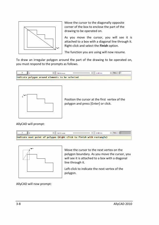
To draw a regular box, you must respond to the prompts as follows:
Position the cursor at one corner of the box that
will enclose the part of the drawing to be
operated on and press [Enter] or click.
AllyCAD will prompt:
3-8 AllyCAD 2010
Move the cursor to the diagonally opposite
corner of the box to enclose the part of the
drawing to be operated on.
As you move the cursor, you will see it is
attached to a box with a diagonal line through it.
Right-click and select the Finish option.
The function you are using will now resume.
To draw an irregular polygon around the part of the drawing to be operated on,
you must respond to the prompts as follows.
Position the cursor at the first vertex of the
polygon and press [Enter] or click.
AllyCAD will prompt:
Move the cursor to the next vertex on the
polygon boundary. As you move the cursor, you
will see it is attached to a box with a diagonal
line through it.
Left-click to indicate the next vertex of the
polygon.
AllyCAD will now prompt:

Screen, Mouse and Keyboard 3-9
As you move the cursor AllyCAD will display a
polyline of the vertices.
Indicate the next vertex and left-click.
AllyCAD will continue to prompt:
AllyCAD will now display a closed polygon based
on the indicated vertices.
Continue to enter polygon vertices. When you
have entered the last vertex, right-click and
select the Finish option.
Right-click and select the Quit option to finish the selection process.
3-10 AllyCAD 2010
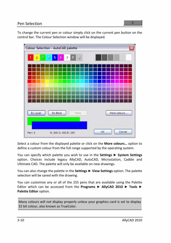
Pen Selection
To change the current pen or colour simply click on the current pen button on the
control bar. The Colour Selection window will be displayed.
Select a colour from the displayed palette or click on the More colours… option to
define a custom colour from the full range supported by the operating system.
You can specify which palette you wish to use in the Settings ► System Settings
option. Choices include legacy AllyCAD, AutoCAD, Microstation, Caddie and
Ultimate CAD. The palette will only be available on new drawings.
You can also change the palette in the Settings ► View Settings option. The palette
selection will be saved with the drawing.
You can customise any or all of the 255 pens that are available using the Palette
Editor which can be accessed from the Programs ► AllyCAD 2010 ► Tools ►
Palette Editor option.
Many colours will not display properly unless your graphics card is set to display
32 bit colour, also known as TrueColor.
Screen, Mouse and Keyboard 3-11
There is also a Colour toolbar, usually at the right side of the CAD screen. This
toolbar only lists the first 16 colour choices, unless you have selected the 31 pen
toolbar option in the System Settings.
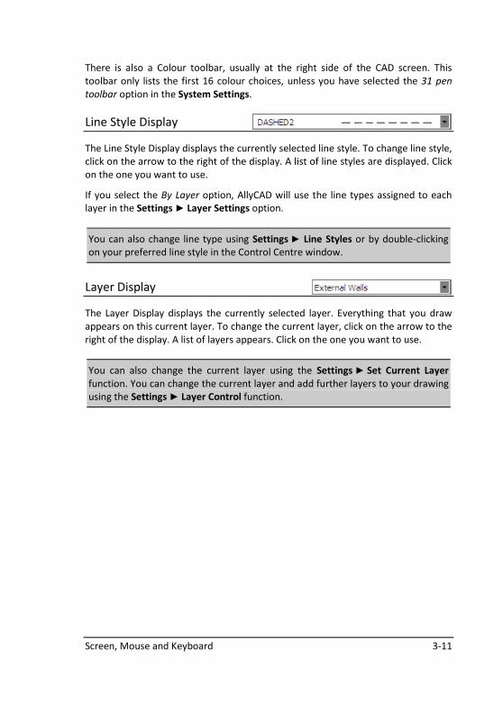
Line Style Display
The Line Style Display displays the currently selected line style. To change line style,
click on the arrow to the right of the display. A list of line styles are displayed. Click
on the one you want to use.
If you select the By Layer option, AllyCAD will use the line types assigned to each
layer in the Settings ► Layer Settings option.
You can also change line type using Settings ► Line Styles or by double-clicking
on your preferred line style in the Control Centre window.
Layer Display
The Layer Display displays the currently selected layer. Everything that you draw
appears on this current layer. To change the current layer, click on the arrow to the
right of the display. A list of layers appears. Click on the one you want to use.
You can also change the current layer using the Settings ► Set Current Layer
function. You can change the current layer and add further layers to your drawing
using the Settings ► Layer Control function.
3-12 AllyCAD 2010
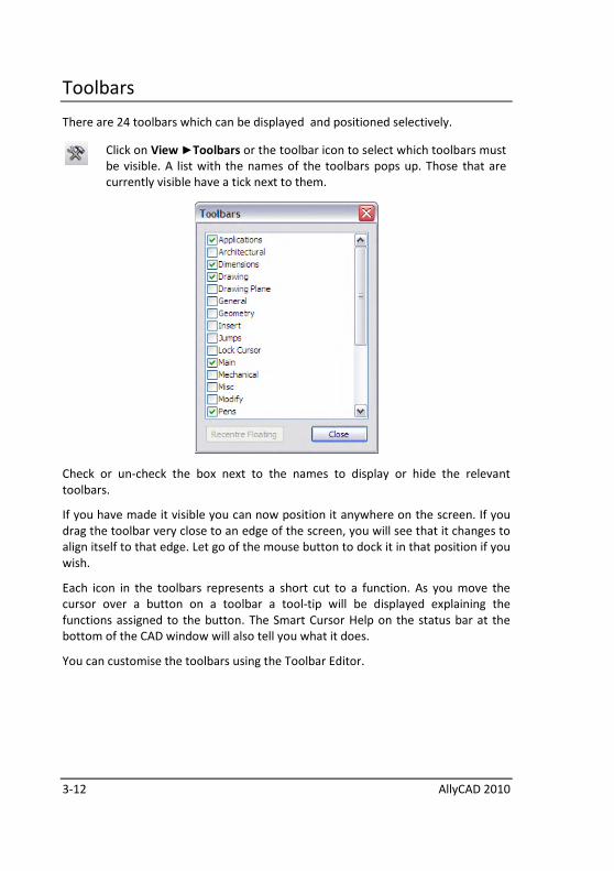
Toolbars
There are 24 toolbars which can be displayed and positioned selectively.
Click on View ►Toolbars or the toolbar icon to select which toolbars must
be visible. A list with the names of the toolbars pops up. Those that are
currently visible have a tick next to them.
Check or un-check the box next to the names to display or hide the relevant
toolbars.
If you have made it visible you can now position it anywhere on the screen. If you
drag the toolbar very close to an edge of the screen, you will see that it changes to
align itself to that edge. Let go of the mouse button to dock it in that position if you
wish.
Each icon in the toolbars represents a short cut to a function. As you move the
cursor over a button on a toolbar a tool-tip will be displayed explaining the
functions assigned to the button. The Smart Cursor Help on the status bar at the
bottom of the CAD window will also tell you what it does.
You can customise the toolbars using the Toolbar Editor.
Screen, Mouse and Keyboard 3-13
Keyboard and Mouse
The keyboard and mouse are both used when drawing with AllyCAD 2010.
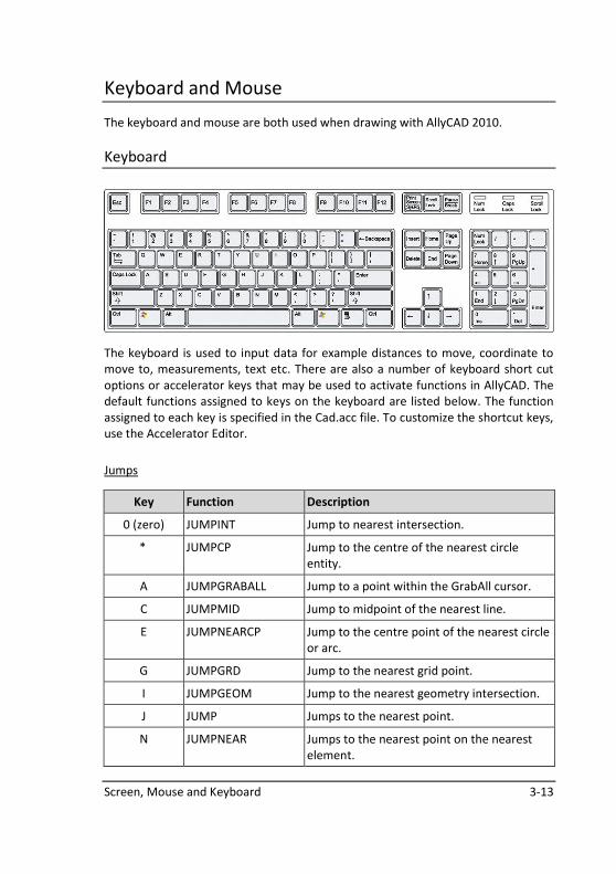
Keyboard
The keyboard is used to input data for example distances to move, coordinate to
move to, measurements, text etc. There are also a number of keyboard short cut
options or accelerator keys that may be used to activate functions in AllyCAD. The
default functions assigned to keys on the keyboard are listed below. The function
assigned to each key is specified in the Cad.acc file. To customize the shortcut keys,
use the Accelerator Editor.
Jumps
Key Function Description
0 (zero) JUMPINT Jump to nearest intersection.
* JUMPCP Jump to the centre of the nearest circle
entity.
A JUMPGRABALL Jump to a point within the GrabAll cursor.
C JUMPMID Jump to midpoint of the nearest line.
E JUMPNEARCP Jump to the centre point of the nearest circle
or arc.
G JUMPGRD Jump to the nearest grid point.
I JUMPGEOM Jump to the nearest geometry intersection.
J JUMP Jumps to the nearest point.
N JUMPNEAR Jumps to the nearest point on the nearest
element.
3-14 AllyCAD 2010
Key Function Description
O JUMPRATIO Jumps to a given ratio between the ends of
the nearest line.
P JUMPPOLAR Jumps a specified diatance at a specified
bearing.
U JUMPCOORD Jumps to specified coordinates.
V JUMPCIRCLEQUAD Jumps to the nearest quadrant point of a
circle.
X JUMPLAST Jumps to the last entered point.
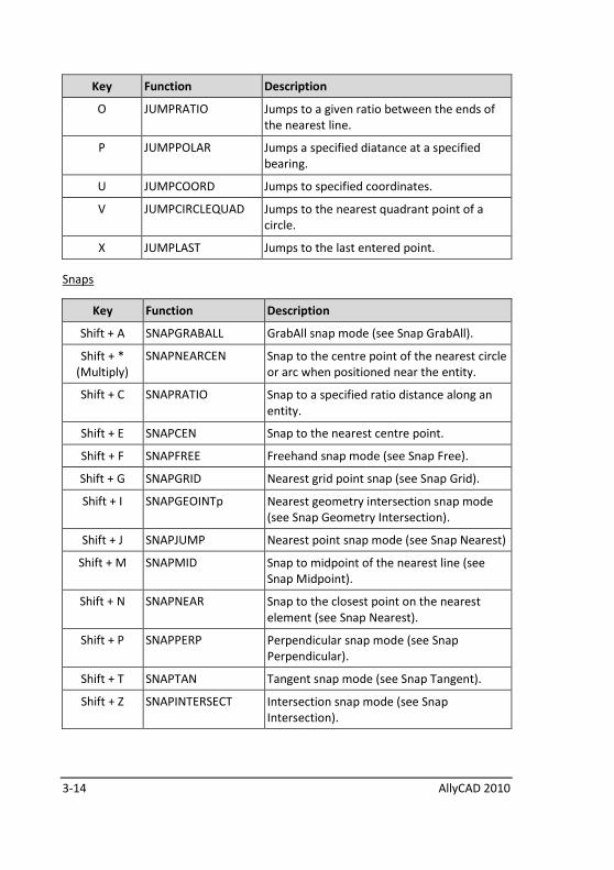
Snaps
Key Function Description
Shift + A SNAPGRABALL GrabAll snap mode (see Snap GrabAll).
Shift + *
(Multiply)
SNAPNEARCEN Snap to the centre point of the nearest circle
or arc when positioned near the entity.
Shift + C SNAPRATIO Snap to a specified ratio distance along an
entity.
Shift + E SNAPCEN Snap to the nearest centre point.
Shift + F SNAPFREE Freehand snap mode (see Snap Free).
Shift + G SNAPGRID Nearest grid point snap (see Snap Grid).
Shift + I SNAPGEOINTp Nearest geometry intersection snap mode
(see Snap Geometry Intersection).
Shift + J SNAPJUMP Nearest point snap mode (see Snap Nearest)
Shift + M SNAPMID Snap to midpoint of the nearest line (see
Snap Midpoint).
Shift + N SNAPNEAR Snap to the closest point on the nearest
element (see Snap Nearest).
Shift + P SNAPPERP Perpendicular snap mode (see Snap
Perpendicular).
Shift + T SNAPTAN Tangent snap mode (see Snap Tangent).
Shift + Z SNAPINTERSECT Intersection snap mode (see Snap
Intersection).
Screen, Mouse and Keyboard 3-15
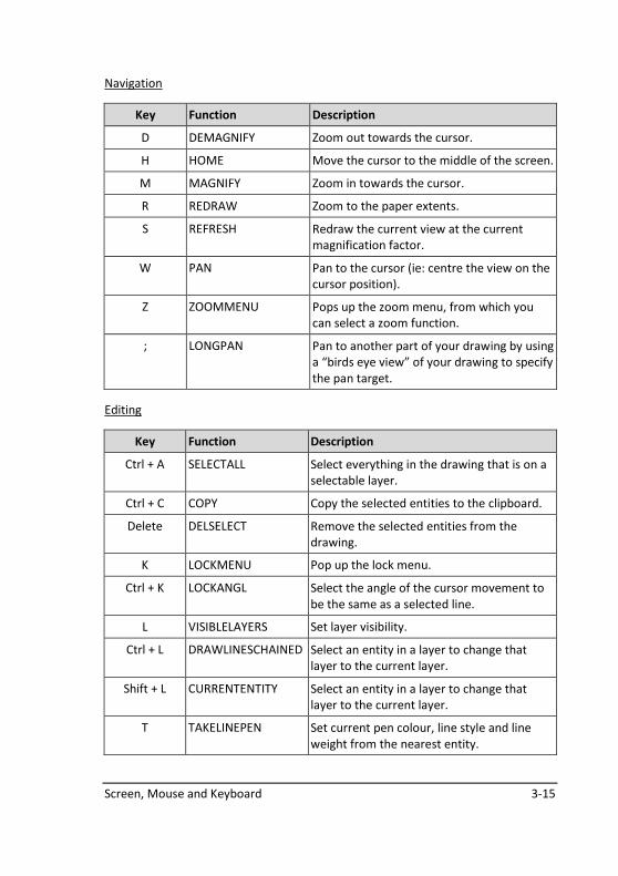
Navigation
Key Function Description
D DEMAGNIFY Zoom out towards the cursor.
H HOME Move the cursor to the middle of the screen.
M MAGNIFY Zoom in towards the cursor.
R REDRAW Zoom to the paper extents.
S REFRESH Redraw the current view at the current
magnification factor.
W PAN Pan to the cursor (ie: centre the view on the
cursor position).
Z ZOOMMENU Pops up the zoom menu, from which you
can select a zoom function.
; LONGPAN Pan to another part of your drawing by using
a “birds eye view” of your drawing to specify
the pan target.
Editing
Key Function Description
Ctrl + A SELECTALL Select everything in the drawing that is on a
selectable layer.
Ctrl + C COPY Copy the selected entities to the clipboard.
Delete DELSELECT Remove the selected entities from the
drawing.
K LOCKMENU Pop up the lock menu.
Ctrl + K LOCKANGL Select the angle of the cursor movement to
be the same as a selected line.
L VISIBLELAYERS Set layer visibility.
Ctrl + L DRAWLINESCHAINED Select an entity in a layer to change that
layer to the current layer.
Shift + L CURRENTENTITY Select an entity in a layer to change that
layer to the current layer.
T TAKELINEPEN Set current pen colour, line style and line
weight from the nearest entity.
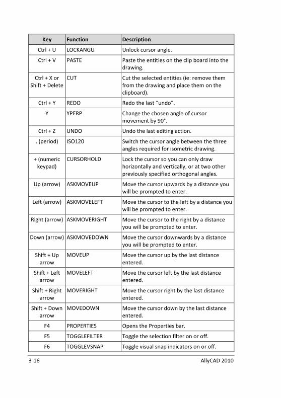
3-16 AllyCAD 2010
Key Function Description
Ctrl + U LOCKANGU Unlock cursor angle.
Ctrl + V PASTE Paste the entities on the clip board into the
drawing.
Ctrl + X or
Shift + Delete
CUT Cut the selected entities (ie: remove them
from the drawing and place them on the
clipboard).
Ctrl + Y REDO Redo the last “undo”.
Y YPERP Change the chosen angle of cursor
movement by 90°.
Ctrl + Z UNDO Undo the last editing action.
. (period) ISO120 Switch the cursor angle between the three
angles required for isometric drawing.
+ (numeric
keypad)
CURSORHOLD Lock the cursor so you can only draw
horizontally and vertically, or at two other
previously specified orthogonal angles.
Up (arrow) ASKMOVEUP Move the cursor upwards by a distance you
will be prompted to enter.
Left (arrow) ASKMOVELEFT Move the cursor to the left by a distance you
will be prompted to enter.
Right (arrow) ASKMOVERIGHT Move the cursor to the right by a distance
you will be prompted to enter.
Down (arrow) ASKMOVEDOWN Move the cursor downwards by a distance
you will be prompted to enter.
Shift + Up
arrow
MOVEUP Move the cursor up by the last distance
entered.
Shift + Left
arrow
MOVELEFT Move the cursor left by the last distance
entered.
Shift + Right
arrow
MOVERIGHT Move the cursor right by the last distance
entered.
Shift + Down
arrow
MOVEDOWN Move the cursor down by the last distance
entered.
F4 PROPERTIES Opens the Properties bar.
F5 TOGGLEFILTER Toggle the selection filter on or off.
F6 TOGGLEVSNAP Toggle visual snap indicators on or off.
Screen, Mouse and Keyboard 3-17
Key Function Description
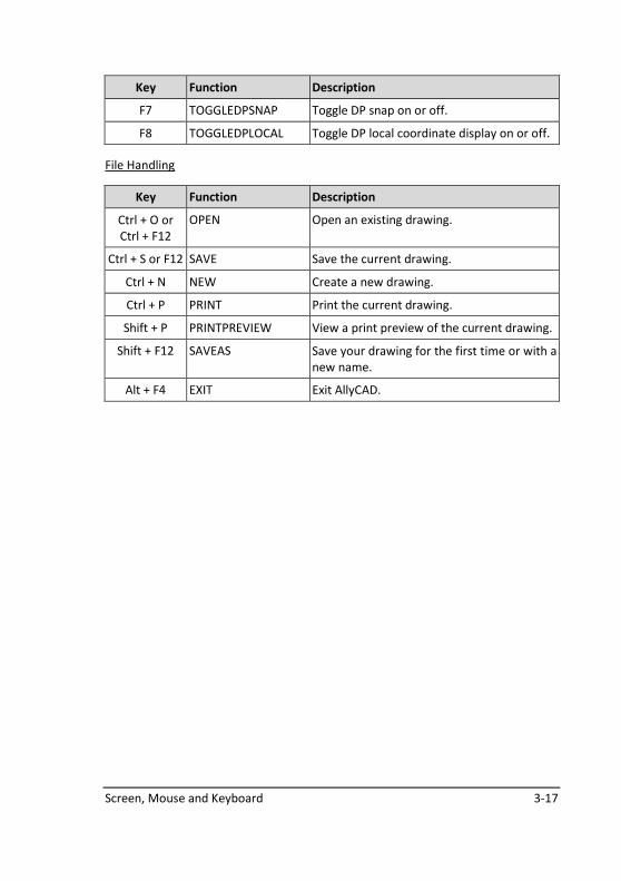
F7 TOGGLEDPSNAP Toggle DP snap on or off.
F8 TOGGLEDPLOCAL Toggle DP local coordinate display on or off.
File Handling
Key Function Description
Ctrl + O or
Ctrl + F12
OPEN Open an existing drawing.
Ctrl + S or F12 SAVE Save the current drawing.
Ctrl + N NEW Create a new drawing.
Ctrl + P PRINT Print the current drawing.
Shift + P PRINTPREVIEW View a print preview of the current drawing.
Shift + F12 SAVEAS Save your drawing for the first time or with a
new name.
Alt + F4 EXIT Exit AllyCAD.
3-18 AllyCAD 2010
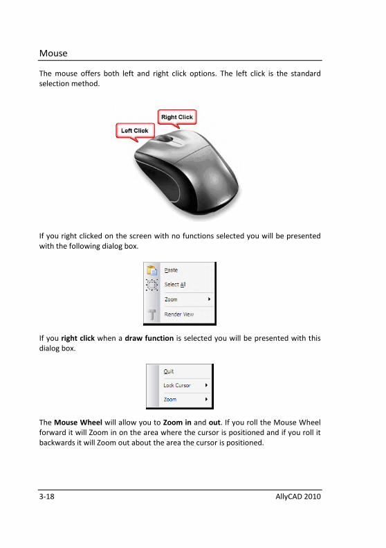
Mouse
The mouse offers both left and right click options. The left click is the standard
selection method.
If you right clicked on the screen with no functions selected you will be presented
with the following dialog box.
If you right click when a draw function is selected you will be presented with this
dialog box.
The Mouse Wheel will allow you to Zoom in and out. If you roll the Mouse Wheel
forward it will Zoom in on the area where the cursor is positioned and if you roll it
backwards it will Zoom out about the area the cursor is positioned.
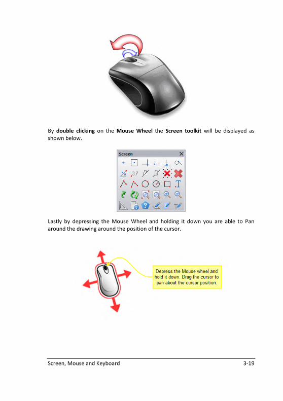
Screen, Mouse and Keyboard 3-19
By double clicking on the Mouse Wheel the Screen toolkit will be displayed as
shown below.
Lastly by depressing the Mouse Wheel and holding it down you are able to Pan
around the drawing around the position of the cursor.

Accurate Drawing 4-1
Accurate Drawing
This chapter lists the methods of accurate cursor movement that allow you to draw
exactly.
The functions listed in this section can be used to position the cursor in preparation
for doing something. For example, you can move the cursor to an exact position
and then draw a geometry line through that position.
Alternatively, they can be used while you are drawing to precise measurements.
For example, you can use them while you are drawing a line, to ensure that the line
is the right length or ends at a particular place.
You can also use some of the methods described here to move selected items or
highlighted nodes on your drawing by fine increments. This feature is called Nudge.
See Move an exact distance up, down, left, right and Move diagonally by giving
exact horizontal / vertical distances.
The items discussed are:
• Move an exact distance up, down, left, or right
• Move diagonally
• Move an exact distance in a specific direction
• Lock cursor movement to an exact angle (ortho mode)
• Move to an exact coordinate location on the screen
• Move exactly to the screen centre
• Move exactly onto an existing part of the drawing
• Drawing with a grid
4-2 AllyCAD 2010
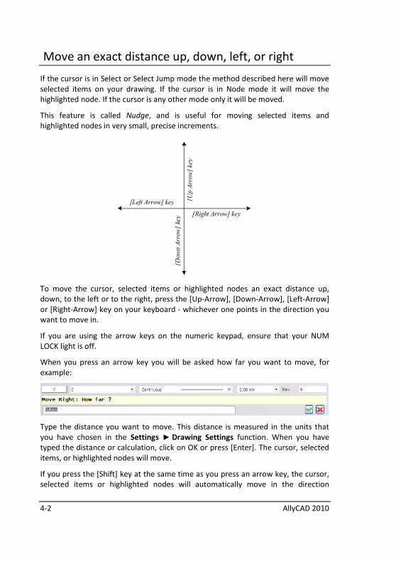
Move an exact distance up, down, left, or right
If the cursor is in Select or Select Jump mode the method described here will move
selected items on your drawing. If the cursor is in Node mode it will move the
highlighted node. If the cursor is any other mode only it will be moved.
This feature is called Nudge, and is useful for moving selected items and
highlighted nodes in very small, precise increments.
[Right Arrow] key
[Left Arrow] key [Up Arrow] key
[Down Arrow] key
To move the cursor, selected items or highlighted nodes an exact distance up,
down, to the left or to the right, press the [Up-Arrow], [Down-Arrow], [Left-Arrow]
or [Right-Arrow] key on your keyboard - whichever one points in the direction you
want to move in.
If you are using the arrow keys on the numeric keypad, ensure that your NUM
LOCK light is off.
When you press an arrow key you will be asked how far you want to move, for
example:
Type the distance you want to move. This distance is measured in the units that
you have chosen in the Settings ► Drawing Settings function. When you have
typed the distance or calculation, click on OK or press [Enter]. The cursor, selected
items, or highlighted nodes will move.
If you press the [Shift] key at the same time as you press an arrow key, the cursor,
selected items or highlighted nodes will automatically move in the direction
Accurate Drawing 4-3
indicated by the arrow. They will move the same distance that you specified the
last time you typed how far you wanted to move in that direction.
See Select and Selection Filters in the Edit Menu for details on how to select
entities and objects. See Select Nodes in the Edit Menu for details on nodes.
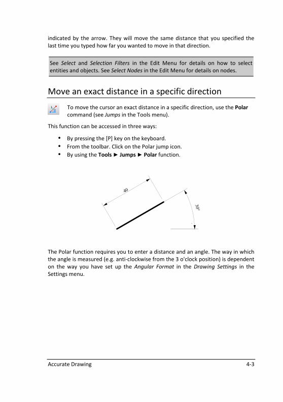
Move an exact distance in a specific direction
To move the cursor an exact distance in a specific direction, use the Polar
command (see Jumps in the Tools menu).
This function can be accessed in three ways:
• By pressing the [P] key on the keyboard.
• From the toolbar. Click on the Polar jump icon.
• By using the Tools ► Jumps ► Polar function.
30°
40
The Polar function requires you to enter a distance and an angle. The way in which
the angle is measured (e.g. anti-clockwise from the 3 o'clock position) is dependent
on the way you have set up the Angular Format in the Drawing Settings in the
Settings menu.
4-4 AllyCAD 2010
Lock cursor to an exact angle (ortho mode)
Drawing horizontal and vertical lines
You can draw horizontal and vertical lines using the arrow keys - see Move an exact
distance up, down, left, or right earlier in this chapter.
Using the Set Square Icon
Enter the function you want to use. For example, choose Draw ► Chained
Line and enter the first point of the line.
Lock the cursor by doing one of the following:
• Press the gray [+] key on the numeric keypad.
• Click on the Set Square icon.
• Select the Tools ► Lock Cursor ► Hold command.
You will now only be able to draw horizontally or vertically and a diamond will
appear at the end of the line you are drawing. You will be able to move the cursor
away from the end of the line you are drawing and snap it onto another entity,
forcing the line you are drawing to end in line with the other entity.
The cursor will automatically unlock when you exit the line drawing function.
However to unlock it manually, do any of the 3 points listed above.
Drawing at other angles
To draw at a non-horizontal angle and its orthogonal, rather like using a set square,
you must first use the Tools ► Lock Cursor function to choose the angle at which
you want to draw. Your chosen angle is then displayed at the bottom right of the
screen. See Lock Cursor in the Tools Menu.
To draw at your chosen angle, enter the function you want to use. For example,
choose Draw ► Chained Line and enter the first point of the line. Then lock the
cursor as described above.
The cursor movement is locked to the specified angle. Once you have locked the
cursor, there are two methods of drawing accurately:
Accurate Drawing 4-5
Drawing accurately using the arrow keys
While the cursor is locked, you can draw lines of accurate length using the Arrow
keys. For example, if the cursor is locked at 60 degrees, the four arrow keys will
move the cursor in quadrants of 60 degrees.
Unlocking the cursor
The cursor will automatically unlock when you exit the Line function. However to
unlock it manually, use the Tools ► Lock Cursor ► Unlock function. Your chosen
angle will still be displayed at the bottom right of the screen until you select the
Tools ► Lock Cursor ► Unlock function.
Move to an exact coordinate location on the screen
To move to a specific coordinate location on the screen, for example the
coordinate position 60 –15, use the Coordinate jump (see the Jumps option in the
Tools menu). This function can be accessed in three ways:
• By pressing the [U] key on the keyboard
• By using the Tools ► Jumps ► Coordinate function from the menu
• By clicking on the Coordinate jump icon
Move exactly to the screen centre
To move to the screen centre, use the Tools ►Jumps ► Home function. Home
moves the cursor to the screen centre whether your screen is magnified, de-
magnified, zoomed or not zoomed. You can also press the [H] key on the keyboard.
4-6 AllyCAD 2010
Move exactly onto an existing part of the drawing
There are two ways of moving exactly onto an existing part of a drawing:
• Jumps or
• Snap modes
A Jump moves your cursor exactly onto an existing part of the drawing, for example
onto the end of a line. It is performed on demand. If you want to accept the point
that you have jumped to, for example as the first point of a line, or as a point
through which a geometry line must pass, etc., you must press [Enter] or your left
mouse button. If you move your mouse off the exact position before you press
[Enter] or your left mouse button, the point will be lost and you will have to
perform the jump again.
When you are in a Snap mode, the cursor moves exactly onto an existing part of the
drawing and the point that is snapped onto is accepted. This action is performed
each time you press [Enter] or the left mouse button.
A Snap mode is useful if you must continuously snap onto the same type of point,
for example if you are drawing lines between grid points and must continually snap
onto those grid points. The Snap mode saves you having to jump to the point and
then accept it as two separate actions.
Accurate Drawing 4-7
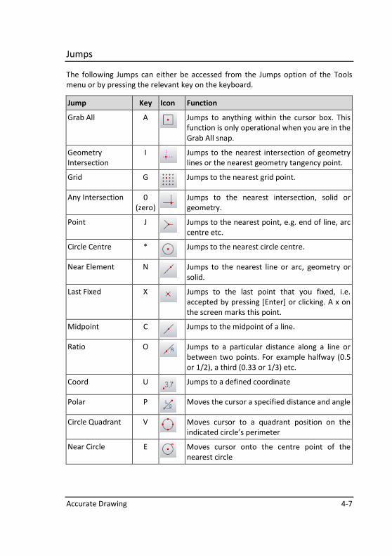
Jumps
The following Jumps can either be accessed from the Jumps option of the Tools
menu or by pressing the relevant key on the keyboard.
Jump Key Icon Function
Grab All A
Jumps to anything within the cursor box. This
function is only operational when you are in the
Grab All snap.
Geometry
Intersection
I
Jumps to the nearest intersection of geometry
lines or the nearest geometry tangency point.
Grid G
Jumps to the nearest grid point.
Any Intersection 0
(zero) Jumps to the nearest intersection, solid or
geometry.
Point J
Jumps to the nearest point, e.g. end of line, arc
centre etc.
Circle Centre *
Jumps to the nearest circle centre.
Near Element N
Jumps to the nearest line or arc, geometry or
solid.
Last Fixed X
Jumps to the last point that you fixed, i.e.
accepted by pressing [Enter] or clicking. A x on
the screen marks this point.
Midpoint C
Jumps to the midpoint of a line.
Ratio O
Jumps to a particular distance along a line or
between two points. For example halfway (0.5
or 1/2), a third (0.33 or 1/3) etc.
Coord U
Jumps to a defined coordinate
Polar P
Moves the cursor a specified distance and angle
Circle Quadrant V
Moves cursor to a quadrant position on the
indicated circle’s perimeter
Near Circle E
Moves cursor onto the centre point of the
nearest circle
4-8 AllyCAD 2010
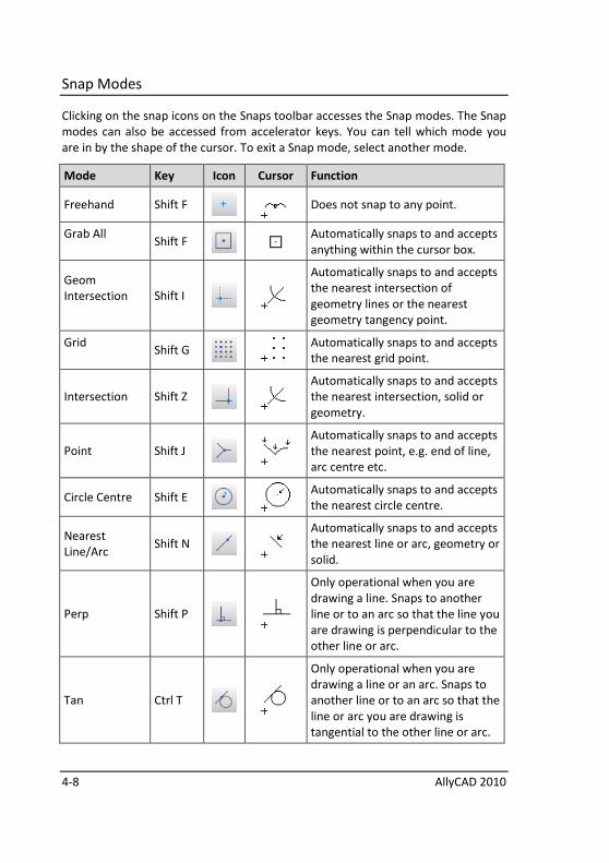
Snap Modes
Clicking on the snap icons on the Snaps toolbar accesses the Snap modes. The Snap
modes can also be accessed from accelerator keys. You can tell which mode you
are in by the shape of the cursor. To exit a Snap mode, select another mode.
Mode Key Icon Cursor Function
Freehand Shift F
Does not snap to any point.
Grab All
Shift F
Automatically snaps to and accepts
anything within the cursor box.
Geom
Intersection
Shift I
Automatically snaps to and accepts
the nearest intersection of
geometry lines or the nearest
geometry tangency point.
Grid
Shift G
Automatically snaps to and accepts
the nearest grid point.
Intersection Shift Z
Automatically snaps to and accepts
the nearest intersection, solid or
geometry.
Point Shift J
Automatically snaps to and accepts
the nearest point, e.g. end of line,
arc centre etc.
Circle Centre Shift E
Automatically snaps to and accepts
the nearest circle centre.
Nearest
Line/Arc Shift N
Automatically snaps to and accepts
the nearest line or arc, geometry or
solid.
Perp Shift P
Only operational when you are
drawing a line. Snaps to another
line or to an arc so that the line you
are drawing is perpendicular to the
other line or arc.
Tan Ctrl T
Only operational when you are
drawing a line or an arc. Snaps to
another line or to an arc so that the
line or arc you are drawing is
tangential to the other line or arc.

Accurate Drawing 4-9
Drawing with a grid
Another method of accurate drawing is to use geometry lines and circles. These
may be used to determine the position of a point, or may be used as guidelines to
trace over.
You can also define a regular or isometric grid and use the
grid points to help you draw.
To create a grid, use the Tools ►Grid function.
Once you have created a grid, you can use the Grid jump, the Grid snap or the Grab
All snap to jump accurately to the grid points.

4-10 AllyCAD 2010
Notes:
Geometry 5-1
Geometry
Geometry is represented by construction lines and circles which can be used as
guide lines for tracing over, for determining the positions of points, for determining
line and arc intersection points and for projecting existing lines to another part of
the drawing.
5-2 AllyCAD 2010
Geometry elements
The following geometric constructions are available:
• Intersecting horizontal and vertical geometry lines (cross).
• Line at a defined angle.
• Line through two points.
• Line parallel to an existing line or circle.
• Circle.
• Up to five concentric circles.
• Circle tangent to two lines.
• Circle tangent to a line and a circle.
• Circle tangent to two circles.
• Circle tangent to three lines.
• Circle through a point and tangent to a line.
• Circle through a point and tangent to a circle.
• Circle through three points.
• Line tangent to a circle.
• Line tangent to two circles.
• Line that is a perpendicular bisector of two points or a line.
Properties of geometry
Geometry has the following properties:
• It has no end points and continues into infinity.
• It is not printed or plotted.
• It is common to all layers.
• Geometry is automatically stored when you save a drawing.
Geometry 5-3
Using geometry as guidelines to trace over
To use geometry as guidelines to trace over, you must first draw the geometry
using the constructions listed.
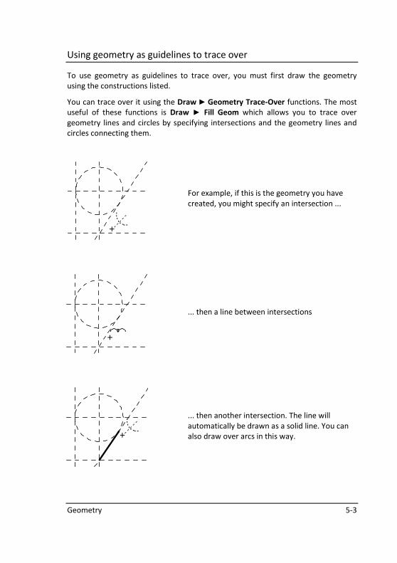
You can trace over it using the Draw ► Geometry Trace-Over functions. The most
useful of these functions is Draw ► Fill Geom which allows you to trace over
geometry lines and circles by specifying intersections and the geometry lines and
circles connecting them.
For example, if this is the geometry you have
created, you might specify an intersection ...
... then a line between intersections
... then another intersection. The line will
automatically be drawn as a solid line. You can
also draw over arcs in this way.
5-4 AllyCAD 2010
Projecting solid lines and arcs to geometry lines and circles
The Geometry ► Make Geometry function projects solid lines and arcs into
geometry lines and arcs. This is useful for projecting lines into another part of the
drawing, or for finding the intersection point between projected lines and arcs.
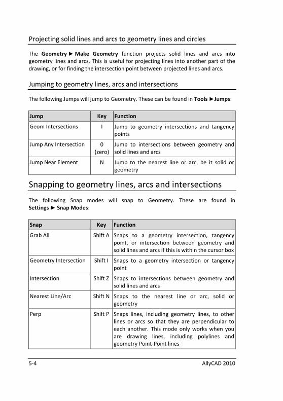
Jumping to geometry lines, arcs and intersections
The following Jumps will jump to Geometry. These can be found in Tools ►Jumps:
Jump Key Function
Geom Intersections I Jump to geometry intersections and tangency
points
Jump Any Intersection 0
(zero)
Jump to intersections between geometry and
solid lines and arcs
Jump Near Element N Jump to the nearest line or arc, be it solid or
geometry
Snapping to geometry lines, arcs and intersections
The following Snap modes will snap to Geometry. These are found in
Settings ► Snap Modes:
Snap Key Function
Grab All Shift A Snaps to a geometry intersection, tangency
point, or intersection between geometry and
solid lines and arcs if this is within the cursor box
Geometry Intersection Shift I Snaps to a geometry intersection or tangency
point
Intersection Shift Z Snaps to intersections between geometry and
solid lines and arcs
Nearest Line/Arc Shift N Snaps to the nearest line or arc, solid or
geometry
Perp Shift P Snaps lines, including geometry lines, to other
lines or arcs so that they are perpendicular to
each another. This mode only works when you
are drawing lines, including polylines and
geometry Point-Point lines
Geometry 5-5
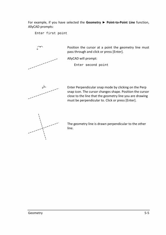
For example, if you have selected the Geometry ► Point-to-Point Line function,
AllyCAD prompts:
Enter first point
Position the cursor at a point the geometry line must
pass through and click or press [Enter].
AllyCAD will prompt:
Enter second point
Enter Perpendicular snap mode by clicking on the Perp
snap icon. The cursor changes shape. Position the cursor
close to the line that the geometry line you are drawing
must be perpendicular to. Click or press [Enter].
The geometry line is drawn perpendicular to the other
line.
5-6 AllyCAD 2010
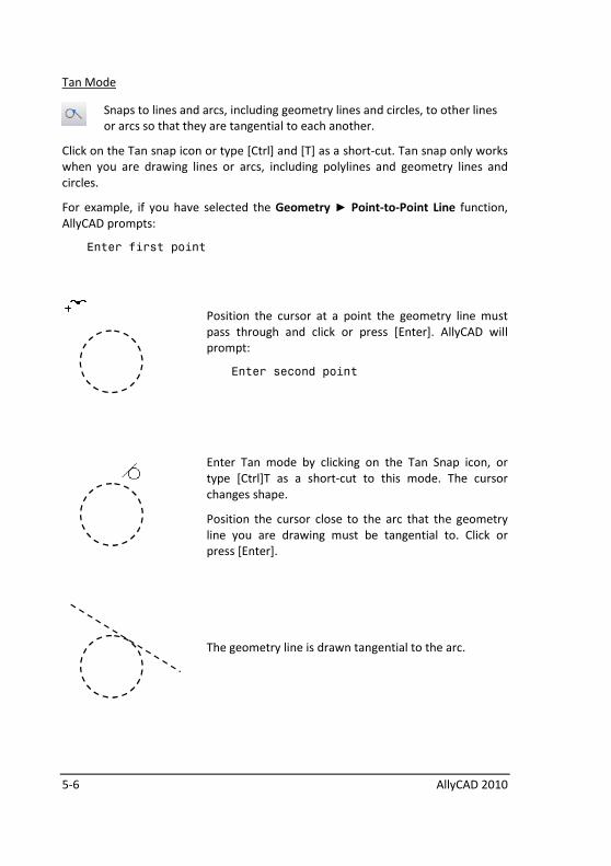
Tan Mode
Snaps to lines and arcs, including geometry lines and circles, to other lines
or arcs so that they are tangential to each another.
Click on the Tan snap icon or type [Ctrl] and [T] as a short-cut. Tan snap only works
when you are drawing lines or arcs, including polylines and geometry lines and
circles.
For example, if you have selected the Geometry ► Point-to-Point Line function,
AllyCAD prompts:
Enter first point
Position the cursor at a point the geometry line must
pass through and click or press [Enter]. AllyCAD will
prompt:
Enter second point
Enter Tan mode by clicking on the Tan Snap icon, or
type [Ctrl]T as a short-cut to this mode. The cursor
changes shape.
Position the cursor close to the arc that the geometry
line you are drawing must be tangential to. Click or
press [Enter].
The geometry line is drawn tangential to the arc.
Geometry 5-7
Switching geometry on and off
If you no longer need your geometry, you can delete it or switch it off.
To switch the geometry off, you select Geometry ►Switch Geometry On/Off. The
message
Geometry display is now OFF
will be briefly displayed in the prompt area.
The geometry will disappear from view, although it will still be there. Even though
you can’t see the geometry you will still be able to jump to it (see Jumping and
Snapping above). You can switch it on again at any time by selecting
Geometry ► Switch Geometry On/Off again. The message
Geometry display is now ON
will appear briefly on the screen.
Deleting geometry
To delete a single geometry line or circle, use the Geometry ► Delete Geometry El
function. To delete all your geometry, use the Geometry ► Delete All Geometry
function. Geometry deletion is permanent. The Undo function will not restore a
deleted geometry element.

5-8 AllyCAD 2010
Notes:

Tutorial 1 - The Screen 6-1
Tutorial 1 - The Screen
This section will demonstrate the basic screen handling features of AllyCAD. You
will learn how to:
• Load a drawing
• Magnify a portion of the drawing
• Pan across a drawing
• De-magnify
• Zoom into portions of the drawing
• Split the screen into different views
6-2 AllyCAD 2010
Important notes to read before you start
Dialog Boxes and Pull-Down Menus
The following chapters assume that you have a basic knowledge of Windows. If you
do not know how to edit a Dialog Box or access a Pull-Down Menu, read the
documentation that came with your copy of Windows.
Clicking
In this tutorial, clicking refers to clicking with your left mouse button unless
otherwise specified.
When a click with your right mouse button is required, the term right click or right
clicking is used.
Clicking is to press and release a mouse button quickly.
Notes
Notes provide alternative methods of accessing functions and extra information for
those who are interested.
Illustrations
The icons, menus, ruler bar and other items that surround the drawing area may be
slightly different on your own screen than the ones shown in the illustrations. This
will not affect your use of the tutorials.
In case you get lost or stuck ...
If you get lost or stuck while you are doing this tutorial, do the following:
• Press the Esc key to cancel all functions.
• Redraw the screen by pressing the short-cut key R, or View ► Redraw
• Repeat the tutorial from the previous subheading (e.g. Magnifying,
Panning etc.)
Tutorial 1 - The Screen 6-3
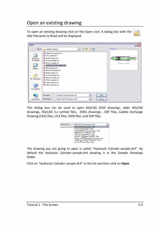
Open an existing drawing
To open an existing drawing click on the Open icon. A dialog box with the
title Filename to Read will be displayed.
This dialog box can be used to open AllyCAD 2010 drawings, older AllyCAD
drawings, AllyCAD 3.x symbol files, DWG drawings , DXF files, Caddie Exchange
Drawing (CEX) files, UCX files, DGN files, and SHP files.
The drawing you are going to open is called “Hydraulic Cylinder.sample.dr4”. By
default the Hydraulic Cylinder.sample.dr4 drawing is in the Sample Drawings
folder.
Click on “Hydraulic Cylinder.sample.dr4” in the list and then click on Open.
6-4 AllyCAD 2010
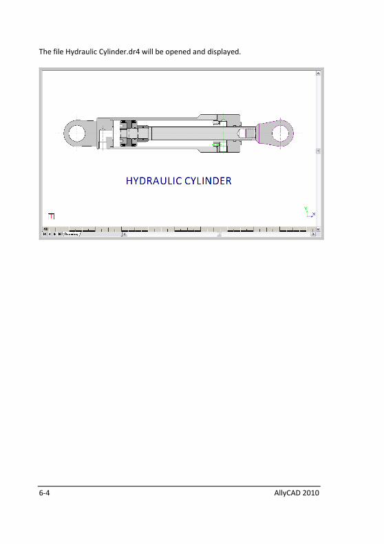
The file Hydraulic Cylinder.dr4 will be opened and displayed.
Tutorial 1 - The Screen 6-5
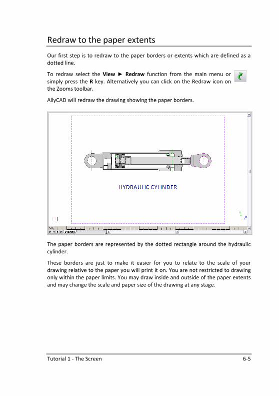
Redraw to the paper extents
Our first step is to redraw to the paper borders or extents which are defined as a
dotted line.
To redraw select the View ► Redraw function from the main menu or
simply press the R key. Alternatively you can click on the Redraw icon on
the Zooms toolbar.
AllyCAD will redraw the drawing showing the paper borders.
The paper borders are represented by the dotted rectangle around the hydraulic
cylinder.
These borders are just to make it easier for you to relate to the scale of your
drawing relative to the paper you will print it on. You are not restricted to drawing
only within the paper limits. You may draw inside and outside of the paper extents
and may change the scale and paper size of the drawing at any stage.
6-6 AllyCAD 2010
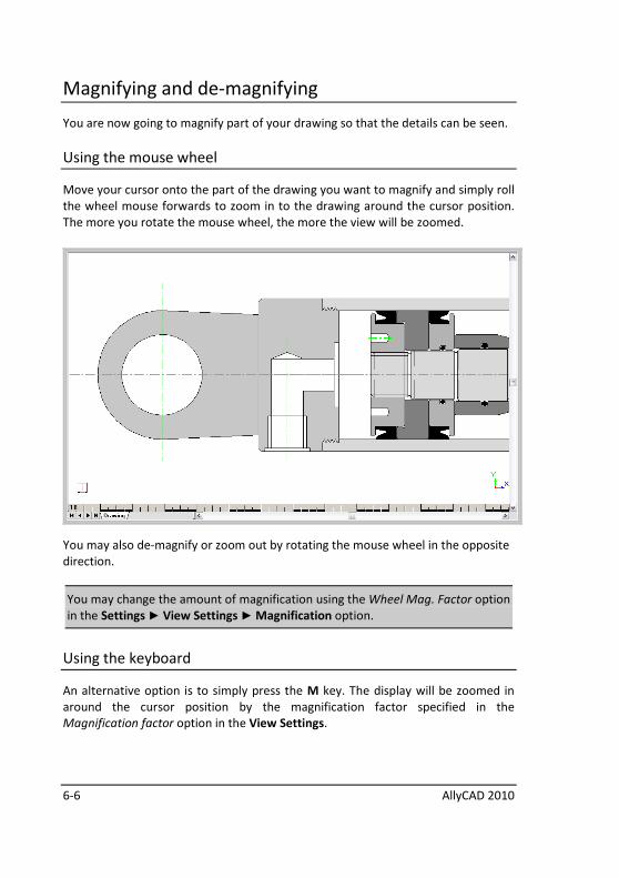
Magnifying and de-magnifying
You are now going to magnify part of your drawing so that the details can be seen.
Using the mouse wheel
Move your cursor onto the part of the drawing you want to magnify and simply roll
the wheel mouse forwards to zoom in to the drawing around the cursor position.
The more you rotate the mouse wheel, the more the view will be zoomed.
You may also de-magnify or zoom out by rotating the mouse wheel in the opposite
direction.
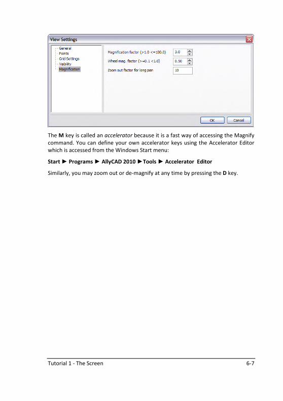
You may change the amount of magnification using the Wheel Mag. Factor option
in the Settings ► View Settings ► Magnification option.
Using the keyboard
An alternative option is to simply press the M key. The display will be zoomed in
around the cursor position by the magnification factor specified in the
Magnification factor option in the View Settings.
Tutorial 1 - The Screen 6-7
The M key is called an accelerator because it is a fast way of accessing the Magnify
command. You can define your own accelerator keys using the Accelerator Editor
which is accessed from the Windows Start menu:
Start ► Programs ► AllyCAD 2010 ►Tools ► Accelerator Editor
Similarly, you may zoom out or de-magnify at any time by pressing the D key.
6-8 AllyCAD 2010
Panning
Panning allows you to move around the drawing while it is magnified. There are
two ways of panning:
Pan - where the part of the drawing at the cursor position is moved to the screen
centre
Long Pan - where you place a box around the part of the drawing you want on the
screen.
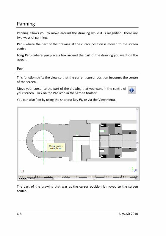
Pan
This function shifts the view so that the current cursor position becomes the centre
of the screen.
Move your cursor to the part of the drawing that you want in the centre of
your screen. Click on the Pan icon in the Screen toolbar.
You can also Pan by using the shortcut key W, or via the View menu.
The part of the drawing that was at the cursor position is moved to the screen
centre.

Tutorial 1 - The Screen 6-9
Long Pan
The Long Pan function zooms out and allows you to position a window over the
area you want to pan to.
Click on the Long Pan icon.
The view will be zoomed out and a floating rectangle will be displayed.
6-10 AllyCAD 2010
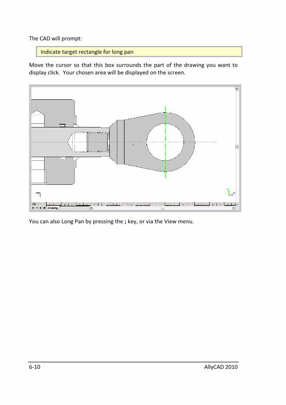
The CAD will prompt:
Indicate target rectangle for long pan
Move the cursor so that this box surrounds the part of the drawing you want to
display click. Your chosen area will be displayed on the screen.
You can also Long Pan by pressing the ; key, or via the View menu.
Tutorial 1 - The Screen 6-11
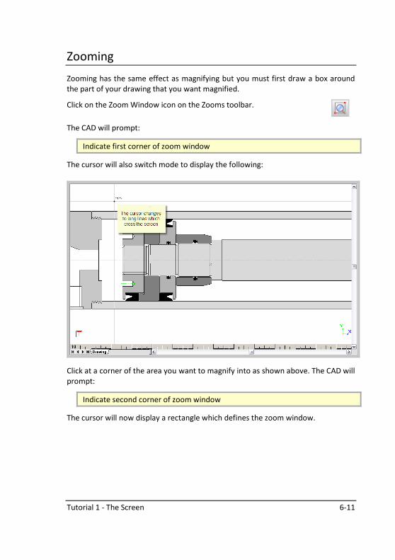
Zooming
Zooming has the same effect as magnifying but you must first draw a box around
the part of your drawing that you want magnified.
Click on the Zoom Window icon on the Zooms toolbar.
The CAD will prompt:
Indicate first corner of zoom window
The cursor will also switch mode to display the following:
Click at a corner of the area you want to magnify into as shown above. The CAD will
prompt:
Indicate second corner of zoom window
The cursor will now display a rectangle which defines the zoom window.
6-12 AllyCAD 2010
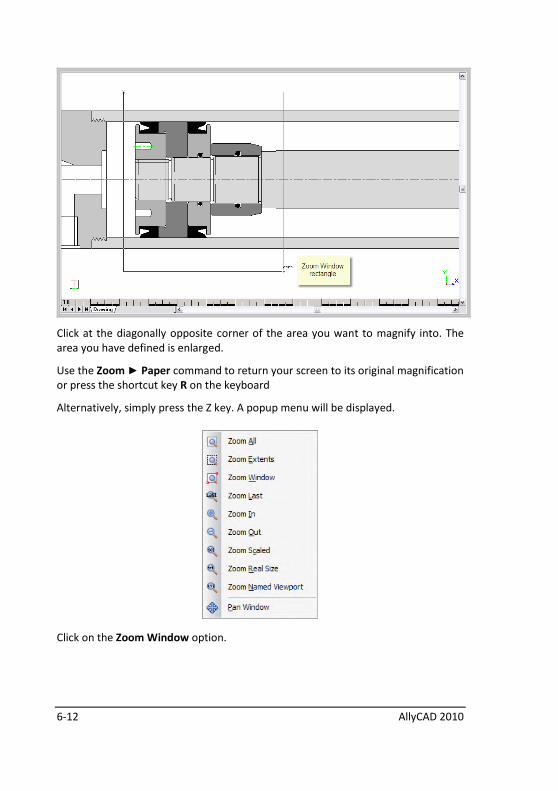
Click at the diagonally opposite corner of the area you want to magnify into. The
area you have defined is enlarged.
Use the Zoom ► Paper command to return your screen to its original magnification
or press the shortcut key R on the keyboard
Alternatively, simply press the Z key. A popup menu will be displayed.
Click on the Zoom Window option.
Tutorial 1 - The Screen 6-13
Splitting the screen into different views
There may be times when you want to work on different parts of your drawing and
either view what is happening in each part easily, or switch between the different
parts quickly.
AllyCAD 2010 supports multiple views which allows you to do just that.
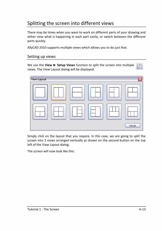
Setting up views
We use the View ► Setup Views function to split the screen into multiple
views. The View Layout dialog will be displayed.
Simply click on the layout that you require. In this case, we are going to split the
screen into 2 views arranged vertically as shown on the second button on the top
left of the View Layout dialog.
The screen will now look like this:
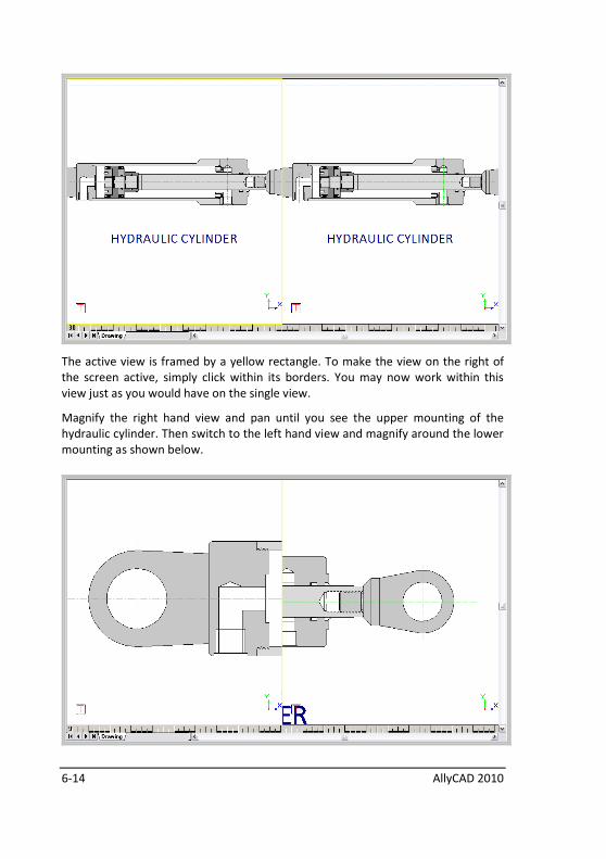
6-14 AllyCAD 2010
The active view is framed by a yellow rectangle. To make the view on the right of
the screen active, simply click within its borders. You may now work within this
view just as you would have on the single view.
Magnify the right hand view and pan until you see the upper mounting of the
hydraulic cylinder. Then switch to the left hand view and magnify around the lower
mounting as shown below.
Tutorial 1 - The Screen 6-15
You may even draw a line from one view into another simply by starting the line in
one view, then activating the second view by clicking on it, and then defining the
endpoint of the line.
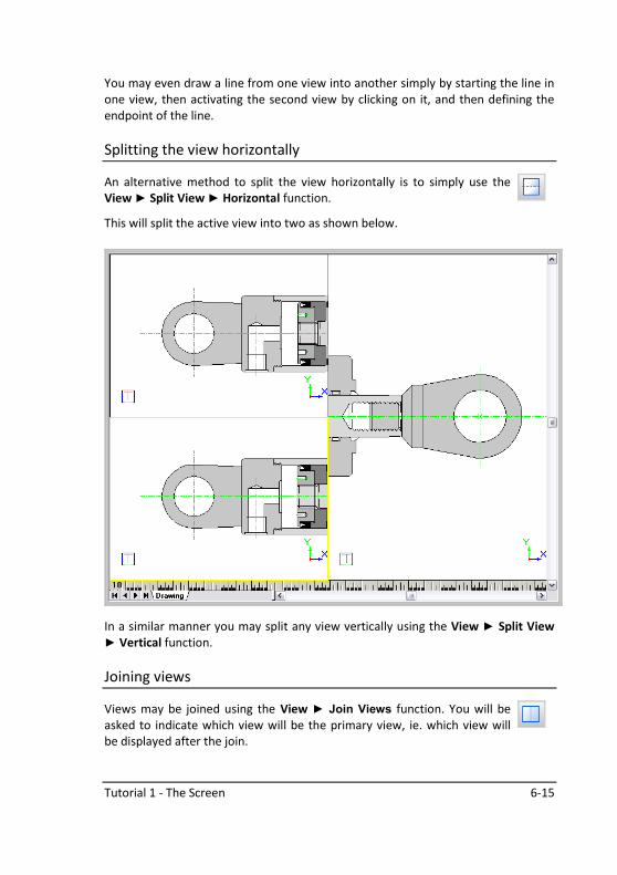
Splitting the view horizontally
An alternative method to split the view horizontally is to simply use the
View ► Split View ► Horizontal function.
This will split the active view into two as shown below.
In a similar manner you may split any view vertically using the View ► Split View
► Vertical function.
Joining views
Views may be joined using the View ► Join Views function. You will be
asked to indicate which view will be the primary view, ie. which view will
be displayed after the join.

6-16 AllyCAD 2010
Finally
Return your screen to its original magnification using the Zoom Paper command by
pressing the shortcut key R (for Redraw) on the keyboard.
You have now completed Tutorial 1. You can either:
• experiment on your own
• exit the CAD using File ► Exit; or
• click on File ► Close to clear the screen. If you do this, the message
Drawing has changed. Do you wish to save it?
will be displayed. Click on (YES) to save ([NO] to discard, or Cancel to
return to drawing .
Tutorial 2 - Viewports and Layouts 7-1
Tutorial 2 - Viewports and Layouts
AllyCAD has a number of tools that you can use to create and print your drawing.
Drawing Space is the area you draw in. It works in the chosen drawing units and
scale that you have set up in the Drawing Settings.
While Drawing Space displays a paper border, you are not limited to drawing within
that border. With the help of viewports you can extract views or portions of your
drawing and place them onto one or more layouts at your chosen position, scale
and rotation.
Viewports are windows into your drawing and layouts are effectively the sheet of
paper that you will ultimately print.
Think of a Drawing Space as the area where you construct your model (or the
object you are drawing), and a layout as the final print, or series of prints. Each
layout can include one or more viewports, each with its own scale and rotation.
Earlier versions of AllyCAD only worked with drawing space and in order to have
different scales it used to use a layer magnification factor. The problem with this
system was that your dimensions would be incorrect if they were not created in the
magnified layer.
Drawing Space, on the other hand, always works in your designated scale,
therefore your dimensions are always correct. If you want to include a detail at a
different scale on your print you would insert a viewport into the layout at the
chosen scale.
This section will explain how to create viewports and layouts with different drawing
elements at various scales.
7-2 AllyCAD 2010
Drawing Space
Take a typical house plan. In order to provide the contractor with all the
information he requires we need to include a plan of the house at a scale of 1:100
as well as the elevations. We also need to include various notes, and possibly even
magnified details at a scale of 1:20.
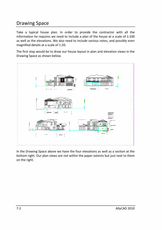
The first step would be to draw our house layout in plan and elevation views in the
Drawing Space as shown below.
In the Drawing Space above we have the four elevations as well as a section at the
bottom right. Our plan views are not within the paper extents but just next to them
on the right.

Tutorial 2 - Viewports and Layouts 7-3
And our notes for the title block are to the left of the paper extents:
Similarly, we also have a legend of our electrical layout in our drawing space.
7-4 AllyCAD 2010
In other words, all our drawing elements are created and maintained in drawing
space, regardless of whether they fit on to the paper extents or not.
So how do we place them onto our layout, which is ultimately what we will print?
Viewports
The first step is to create a number of viewports. These are “windows” or views
into our larger drawing and they can even be useful during the drawing creation.
For instance, often when drawing an elevation we would like to refer back to the
plan and vice versa.
By creating two viewports, one for the plan and one for the elevation we are
working on, we can switch between the two views quite quickly.
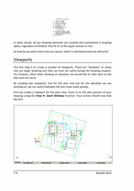
First we create a viewport for the plan view. Zoom in to the plan portion of your
drawing using the View ► Zoom Window function. Your screen should now look
like this:
Tutorial 2 - Viewports and Layouts 7-5
We use the View ► Viewports ► Define Named Viewport function to create the
viewport we need. You will be prompted to specify a name for the viewport with:
Enter new name for Named Viewport
Type in the name “Plan” and click on the OK button or press Enter.
You will now be asked to:
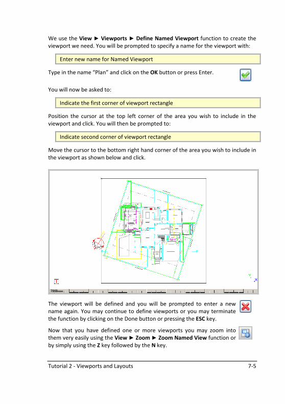
Indicate the first corner of viewport rectangle
Position the cursor at the top left corner of the area you wish to include in the
viewport and click. You will then be prompted to:
Indicate second corner of viewport rectangle
Move the cursor to the bottom right hand corner of the area you wish to include in
the viewport as shown below and click.
The viewport will be defined and you will be prompted to enter a new
name again. You may continue to define viewports or you may terminate
the function by clicking on the Done button or pressing the ESC key.
Now that you have defined one or more viewports you may zoom into
them very easily using the View ► Zoom ► Zoom Named View function or
by simply using the Z key followed by the N key.
7-6 AllyCAD 2010
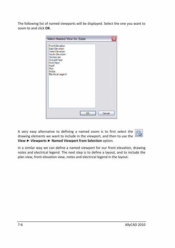
The following list of named viewports will be displayed. Select the one you want to
zoom to and click OK.
A very easy alternative to defining a named zoom is to first select the
drawing elements we want to include in the viewport, and then to use the
View ► Viewports ► Named Viewport from Selection option.
In a similar way we can define a named viewport for our front elevation, drawing
notes and electrical legend. The next step is to define a layout, and to include the
plan view, front elevation view, notes and electrical legend in the layout.
Tutorial 2 - Viewports and Layouts 7-7
Layouts
Think of a layout as your paper print. Onto the layout we can add a title block, a
frame and any text or other drawing entities we wish, but most importantly, we
can insert our viewports into the layout at the position we want and at the scale
that we want.
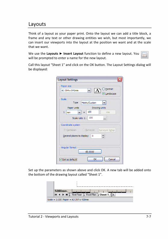
We use the Layouts ► Insert Layout function to define a new layout. You
will be prompted to enter a name for the new layout.
Call this layout “Sheet 1” and click on the OK button. The Layout Settings dialog will
be displayed:
Set up the parameters as shown above and click OK. A new tab will be added onto
the bottom of the drawing layout called “Sheet 1”.
7-8 AllyCAD 2010
You will now be asked if you want to add a default viewport to the new layout.
Click on No as we want to insert our pre-defined viewports. You will be taken to the
newly created layout which will be a blank sheet of paper.
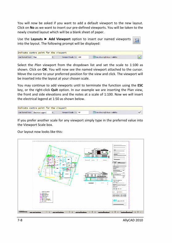
Use the Layouts ► Add Viewport option to insert our named viewports
into the layout. The following prompt will be displayed:
Select the Plan viewport from the dropdown list and set the scale to 1:100 as
shown. Click on OK. You will now see the named viewport attached to the cursor.
Move the cursor to your preferred position for the view and click. The viewport will
be inserted into the layout at your chosen scale.
You may continue to add viewports until to terminate the function using the ESC
key, or the right-click Quit option. In our example we are inserting the Plan view,
the front and side elevations and the notes at a scale of 1:100. Now we will insert
the electrical legend at 1:50 as shown below.
If you prefer another scale for any viewport simply type in the preferred value into
the Viewport Scale box.
Our layout now looks like this:
Tutorial 2 - Viewports and Layouts 7-9
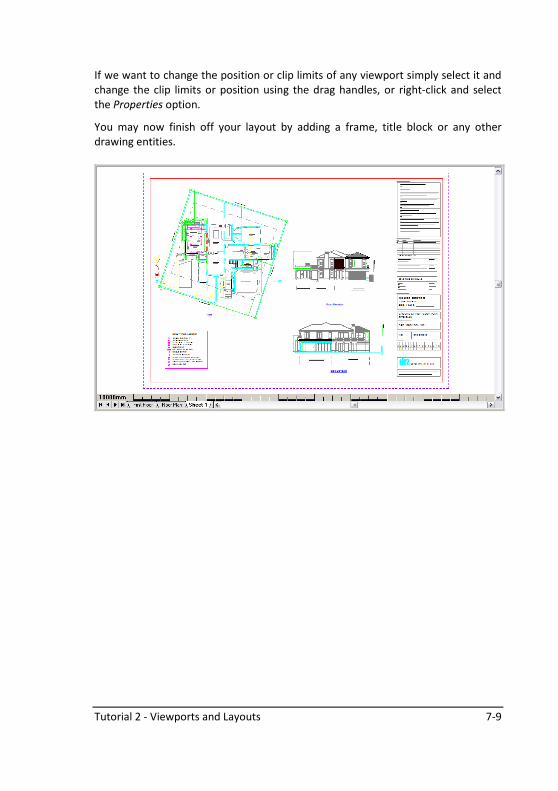
If we want to change the position or clip limits of any viewport simply select it and
change the clip limits or position using the drag handles, or right-click and select
the Properties option.
You may now finish off your layout by adding a frame, title block or any other
drawing entities.

7-10 AllyCAD 2010
Notes:
3D Drawing and Solid Form 8-1
Tutorial 3 - 3D Drawing and Solid Form
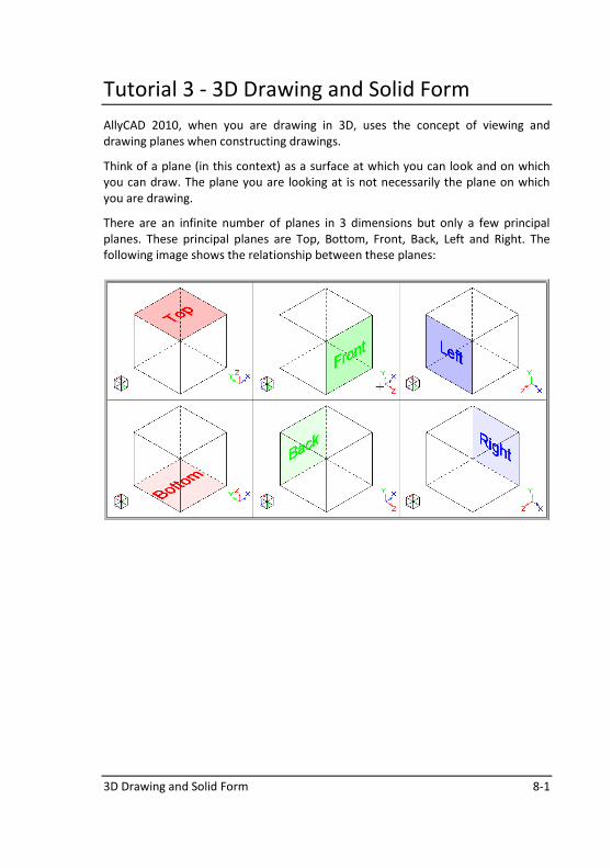
AllyCAD 2010, when you are drawing in 3D, uses the concept of viewing and
drawing planes when constructing drawings.
Think of a plane (in this context) as a surface at which you can look and on which
you can draw. The plane you are looking at is not necessarily the plane on which
you are drawing.
There are an infinite number of planes in 3 dimensions but only a few principal
planes. These principal planes are Top, Bottom, Front, Back, Left and Right. The
following image shows the relationship between these planes:

8-2 AllyCAD 2010
Viewing planes
When you start a new drawing in AllyCAD 2010 the view plane is automatically set
to the Top plane (as if you were creating a standard 2D drawing) and the drawing
plane is also set to the Top plane.
When opening a new
drawing, the View Plane is
automatically set to the
Top plane
The Drawing Plane
is also set to the
Top plane
If you only need a 2D drawing then you will not have to change the view or drawing
plane at all. You can set the Viewing plane to the Top, Front, Left, Bottom, Back or
Right view by clicking on the respective icon (see below) in the View Axis toolbar or
you could select View ►View Direction and selecting the view you would like to
draw in.
3D Drawing and Solid Form 8-3
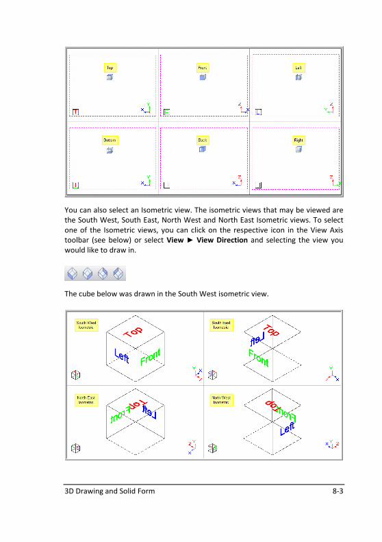
You can also select an Isometric view. The isometric views that may be viewed are
the South West, South East, North West and North East Isometric views. To select
one of the Isometric views, you can click on the respective icon in the View Axis
toolbar (see below) or select View ► View Direction and selecting the view you
would like to draw in.
The cube below was drawn in the South West isometric view.
8-4 AllyCAD 2010
Drawing Planes
To create a 3 dimensional drawing, you need to understand how to operate with
planes.
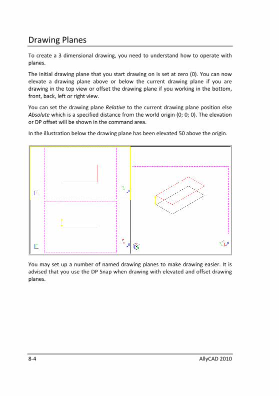
The initial drawing plane that you start drawing on is set at zero (0). You can now
elevate a drawing plane above or below the current drawing plane if you are
drawing in the top view or offset the drawing plane if you working in the bottom,
front, back, left or right view.
You can set the drawing plane Relative to the current drawing plane position else
Absolute which is a specified distance from the world origin (0; 0; 0). The elevation
or DP offset will be shown in the command area.
In the illustration below the drawing plane has been elevated 50 above the origin.
You may set up a number of named drawing planes to make drawing easier. It is
advised that you use the DP Snap when drawing with elevated and offset drawing
planes.
3D Drawing and Solid Form 8-5
3D Drawing
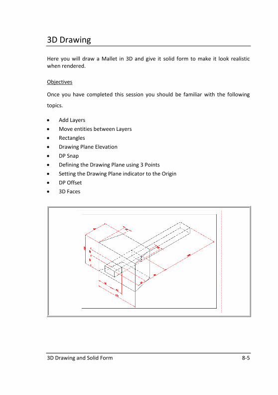
Here you will draw a Mallet in 3D and give it solid form to make it look realistic
when rendered.
Objectives
Once you have completed this session you should be familiar with the following
topics.
• Add Layers
• Move entities between Layers
• Rectangles
• Drawing Plane Elevation
• DP Snap
• Defining the Drawing Plane using 3 Points
• Setting the Drawing Plane indicator to the Origin
• DP Offset
• 3D Faces
8-6 AllyCAD 2010
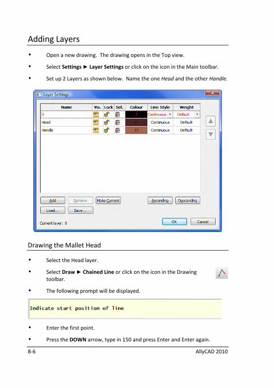
Adding Layers
• Open a new drawing. The drawing opens in the Top view.
• Select Settings ► Layer Settings or click on the icon in the Main toolbar.
• Set up 2 Layers as shown below. Name the one Head and the other Handle.
Drawing the Mallet Head
• Select the Head layer.
• Select Draw ► Chained Line or click on the icon in the Drawing
toolbar.
• The following prompt will be displayed.
• Enter the first point.
• Press the DOWN arrow, type in 150 and press Enter and Enter again.
3D Drawing and Solid Form 8-7
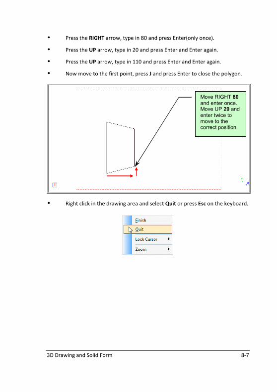
• Press the RIGHT arrow, type in 80 and press Enter(only once).
• Press the UP arrow, type in 20 and press Enter and Enter again.
• Press the UP arrow, type in 110 and press Enter and Enter again.
• Now move to the first point, press J and press Enter to close the polygon.
• Right click in the drawing area and select Quit or press Esc on the keyboard.
Move RIGHT 80 and enter once. Move UP 20 and enter twice to move to the correct position.

8-8 AllyCAD 2010
View Directions
• Select View ► View Direction ► SW Isometric or click on the icon
in the View Axis toolbar.
We want to draw the other side of the head exactly 100mm above the existing
side. To do that we will elevate the DP by 100mm.
DP Elevation
• Select View ► Drawing Plane ► Elevate DP or click on the icon in
the Drawing Plane toolbar. The Elevate DP dialog will be
displayed.
Change the View Direction to SW Isometric.
3D Drawing and Solid Form 8-9
• Check the Relative Elevation radio button and type 100. Click OK. Your DP
will now be elevated by 100mm in the direction of the “RED” arrow of the
Drawing Plane indicator.
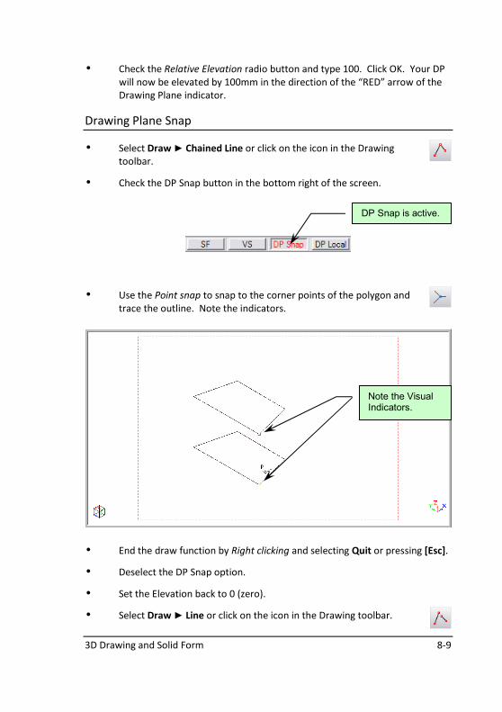
Drawing Plane Snap
• Select Draw ► Chained Line or click on the icon in the Drawing
toolbar.
• Check the DP Snap button in the bottom right of the screen.
• Use the Point snap to snap to the corner points of the polygon and
trace the outline. Note the indicators.
• End the draw function by Right clicking and selecting Quit or pressing [Esc].
• Deselect the DP Snap option.
• Set the Elevation back to 0 (zero).
• Select Draw ► Line or click on the icon in the Drawing toolbar.
Note the Visual Indicators.
DP Snap is active.
8-10 AllyCAD 2010
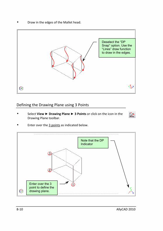
• Draw in the edges of the Mallet head.
Defining the Drawing Plane using 3 Points
• Select View ► Drawing Plane ► 3 Points or click on the icon in the
Drawing Plane toolbar.
• Enter over the 3 points as indicated below.
Deselect the “DP Snap” option. Use the “Lines” draw function to draw in the edges.
Note that the DP Indicator changes.
Enter over the 3 point to define the drawing plane.
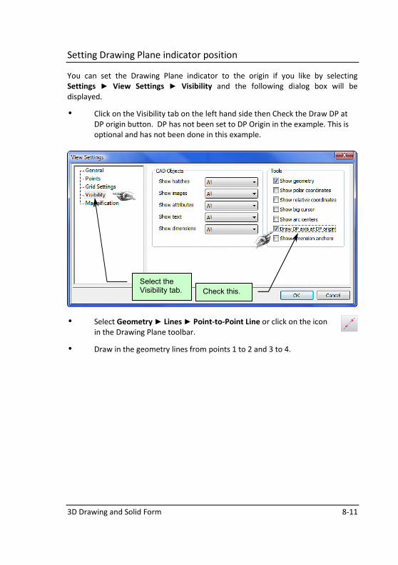
3D Drawing and Solid Form 8-11
Setting Drawing Plane indicator position
You can set the Drawing Plane indicator to the origin if you like by selecting
Settings ► View Settings ► Visibility and the following dialog box will be
displayed.
• Click on the Visibility tab on the left hand side then Check the Draw DP at
DP origin button. DP has not been set to DP Origin in the example. This is
optional and has not been done in this example.
• Select Geometry ► Lines ► Point-to-Point Line or click on the icon
in the Drawing Plane toolbar.
• Draw in the geometry lines from points 1 to 2 and 3 to 4.
Select the Visibility tab. Check this.
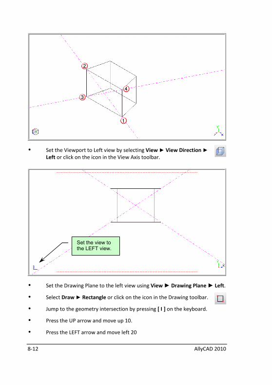
8-12 AllyCAD 2010
• Set the Viewport to Left view by selecting View ► View Direction ►
Left or click on the icon in the View Axis toolbar.
• Set the Drawing Plane to the left view using View ► Drawing Plane ► Left.
• Select Draw ► Rectangle or click on the icon in the Drawing toolbar.
• Jump to the geometry intersection by pressing [ I ] on the keyboard.
• Press the UP arrow and move up 10.
• Press the LEFT arrow and move left 20
Set the view to the LEFT view.
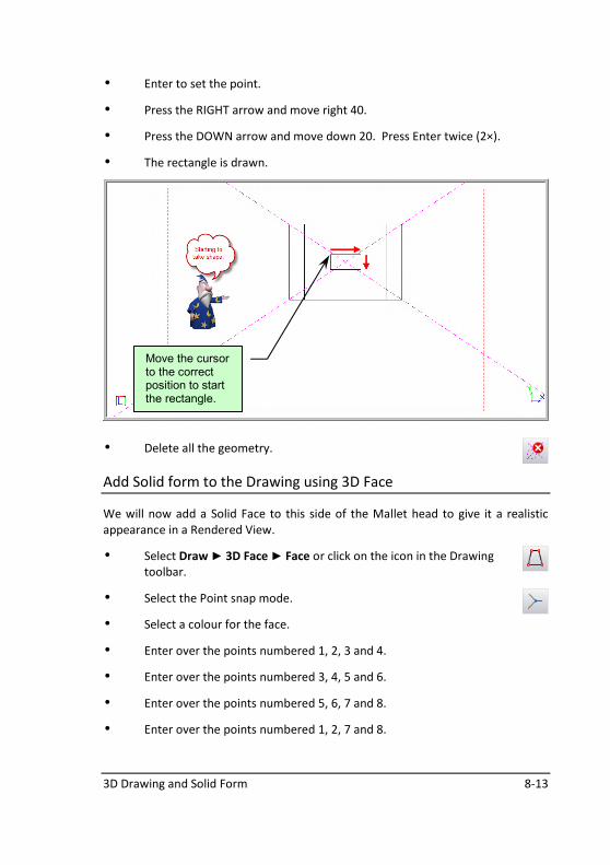
3D Drawing and Solid Form 8-13
• Enter to set the point.
• Press the RIGHT arrow and move right 40.
• Press the DOWN arrow and move down 20. Press Enter twice (2×).
• The rectangle is drawn.
• Delete all the geometry.
Add Solid form to the Drawing using 3D Face
We will now add a Solid Face to this side of the Mallet head to give it a realistic
appearance in a Rendered View.
• Select Draw ► 3D Face ► Face or click on the icon in the Drawing
toolbar.
• Select the Point snap mode.
• Select a colour for the face.
• Enter over the points numbered 1, 2, 3 and 4.
• Enter over the points numbered 3, 4, 5 and 6.
• Enter over the points numbered 5, 6, 7 and 8.
• Enter over the points numbered 1, 2, 7 and 8.
Move the cursor to the correct position to start the rectangle.
8-14 AllyCAD 2010
• Select View ► View Direction ► SW Isometric or click on the icon in
the View Axis toolbar.
Drawing Plane Offset
By using the DP offset value, you can draw at an offset from a DP (in the direction
of the RED arrow).
• Type in -80 in the DP Off text box and press Enter.
• Select Draw ► Rectangle or click on the icon in the Drawing toolbar.
• Check the DP Snap button in the bottom right of the screen.
• Select the Point snap mode.
• Enter over the corners numbered 1 and 2.
Set the offset to -80.
DP Snap is active.
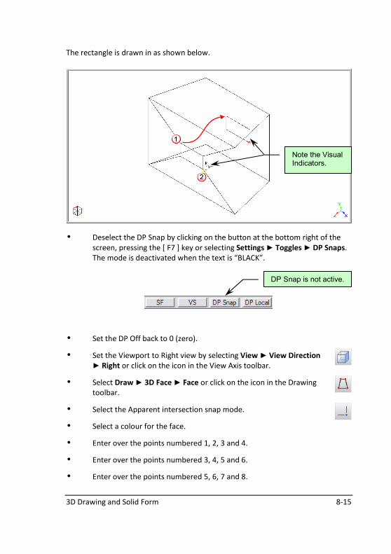
3D Drawing and Solid Form 8-15
The rectangle is drawn in as shown below.
• Deselect the DP Snap by clicking on the button at the bottom right of the
screen, pressing the [ F7 ] key or selecting Settings ► Toggles ► DP Snaps.
The mode is deactivated when the text is “BLACK”.
• Set the DP Off back to 0 (zero).
• Set the Viewport to Right view by selecting View ► View Direction
► Right or click on the icon in the View Axis toolbar.
• Select Draw ► 3D Face ► Face or click on the icon in the Drawing
toolbar.
• Select the Apparent intersection snap mode.
• Select a colour for the face.
• Enter over the points numbered 1, 2, 3 and 4.
• Enter over the points numbered 3, 4, 5 and 6.
• Enter over the points numbered 5, 6, 7 and 8.
Note the Visual Indicators.
DP Snap is not active.
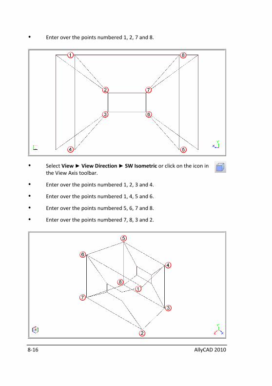
8-16 AllyCAD 2010
• Enter over the points numbered 1, 2, 7 and 8.
• Select View ► View Direction ► SW Isometric or click on the icon in
the View Axis toolbar.
• Enter over the points numbered 1, 2, 3 and 4.
• Enter over the points numbered 1, 4, 5 and 6.
• Enter over the points numbered 5, 6, 7 and 8.
• Enter over the points numbered 7, 8, 3 and 2.
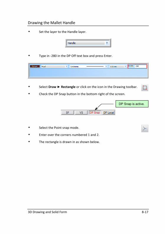
3D Drawing and Solid Form 8-17
Drawing the Mallet Handle
• Set the layer to the Handle layer.
• Type in -280 in the DP Off text box and press Enter.
• Select Draw ► Rectangle or click on the icon in the Drawing toolbar.
• Check the DP Snap button in the bottom right of the screen.
• Select the Point snap mode.
• Enter over the corners numbered 1 and 2.
• The rectangle is drawn in as shown below.
DP Snap is active.
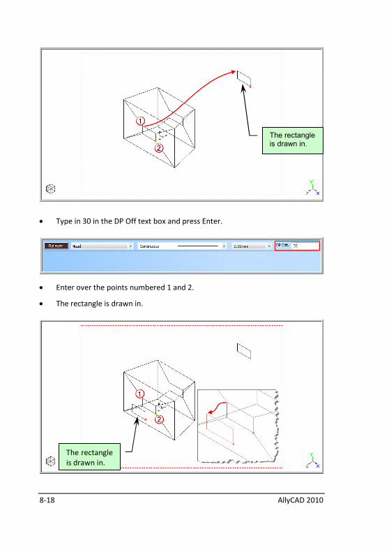
8-18 AllyCAD 2010
• Type in 30 in the DP Off text box and press Enter.
• Enter over the points numbered 1 and 2.
• The rectangle is drawn in.
The rectangle is drawn in.
The rectangle
is drawn in.
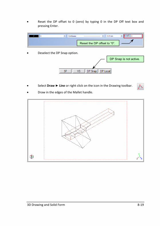
3D Drawing and Solid Form 8-19
• Reset the DP offset to 0 (zero) by typing 0 in the DP Off text box and
pressing Enter.
• Deselect the DP Snap option.
• Select Draw ► Line or right click on the icon in the Drawing toolbar.
• Draw in the edges of the Mallet handle.
Reset the DP offset to “0”.
DP Snap is not active.
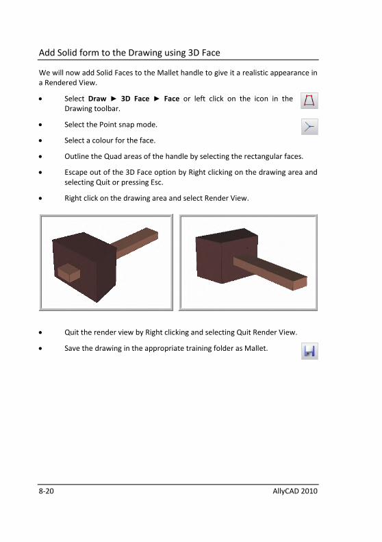
8-20 AllyCAD 2010
Add Solid form to the Drawing using 3D Face
We will now add Solid Faces to the Mallet handle to give it a realistic appearance in
a Rendered View.
• Select Draw ► 3D Face ► Face or left click on the icon in the
Drawing toolbar.
• Select the Point snap mode.
• Select a colour for the face.
• Outline the Quad areas of the handle by selecting the rectangular faces.
• Escape out of the 3D Face option by Right clicking on the drawing area and
selecting Quit or pressing Esc.
• Right click on the drawing area and select Render View.
• Quit the render view by Right clicking and selecting Quit Render View.
• Save the drawing in the appropriate training folder as Mallet.
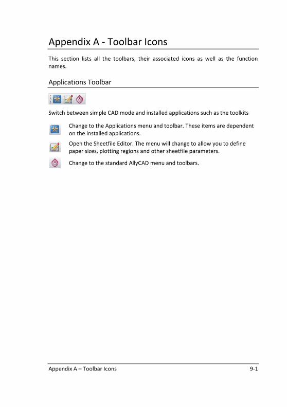
Appendix A – Toolbar Icons 9-1
Appendix A - Toolbar Icons
This section lists all the toolbars, their associated icons as well as the function
names.
Applications Toolbar
Switch between simple CAD mode and installed applications such as the toolkits
Change to the Applications menu and toolbar. These items are dependent
on the installed applications.
Open the Sheetfile Editor. The menu will change to allow you to define
paper sizes, plotting regions and other sheetfile parameters.
Change to the standard AllyCAD menu and toolbars.
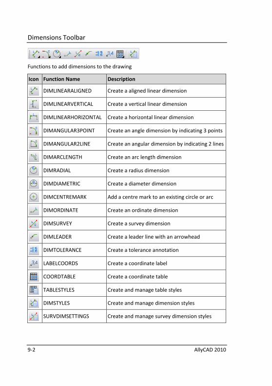
9-2 AllyCAD 2010
Dimensions Toolbar
Functions to add dimensions to the drawing
Icon Function Name Description
DIMLINEARALIGNED Create a aligned linear dimension
DIMLINEARVERTICAL Create a vertical linear dimension
DIMLINEARHORIZONTAL Create a horizontal linear dimension
DIMANGULAR3POINT Create an angle dimension by indicating 3 points
DIMANGULAR2LINE Create an angular dimension by indicating 2 lines
DIMARCLENGTH Create an arc length dimension
DIMRADIAL Create a radius dimension
DIMDIAMETRIC Create a diameter dimension
DIMCENTREMARK Add a centre mark to an existing circle or arc
DIMORDINATE Create an ordinate dimension
DIMSURVEY Create a survey dimension
DIMLEADER Create a leader line with an arrowhead
DIMTOLERANCE Create a tolerance annotation
LABELCOORDS Create a coordinate label
COORDTABLE Create a coordinate table
TABLESTYLES Create and manage table styles
DIMSTYLES Create and manage dimension styles
SURVDIMSETTINGS Create and manage survey dimension styles
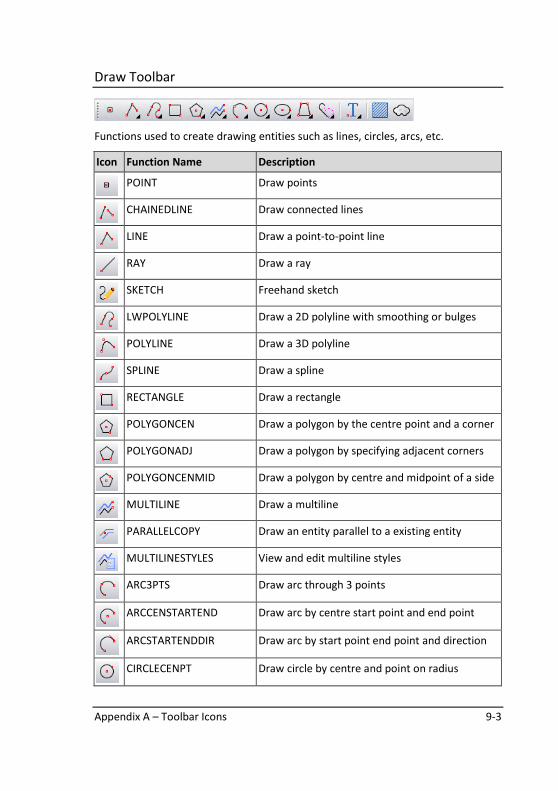
Appendix A – Toolbar Icons 9-3
Draw Toolbar
Functions used to create drawing entities such as lines, circles, arcs, etc.
Icon Function Name Description
POINT Draw points
CHAINEDLINE Draw connected lines
LINE Draw a point-to-point line
RAY Draw a ray
SKETCH Freehand sketch
LWPOLYLINE Draw a 2D polyline with smoothing or bulges
POLYLINE Draw a 3D polyline
SPLINE Draw a spline
RECTANGLE Draw a rectangle
POLYGONCEN Draw a polygon by the centre point and a corner
POLYGONADJ Draw a polygon by specifying adjacent corners
POLYGONCENMID Draw a polygon by centre and midpoint of a side
MULTILINE Draw a multiline
PARALLELCOPY Draw an entity parallel to a existing entity
MULTILINESTYLES View and edit multiline styles
ARC3PTS Draw arc through 3 points
ARCCENSTARTEND Draw arc by centre start point and end point
ARCSTARTENDDIR Draw arc by start point end point and direction
CIRCLECENPT Draw circle by centre and point on radius
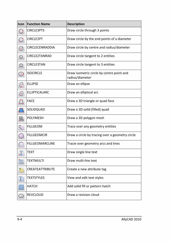
9-4 AllyCAD 2010
Icon Function Name Description
CIRCLE3PTS Draw circle through 3 points
CIRCLE2PT Draw circle by the end points of a diameter
CIRCLECENRADDIA Draw circle by centre and radius/diameter
CIRCLE2TANRAD Draw circle tangent to 2 entities
CIRCLE3TAN Draw circle tangent to 3 entities
ISOCIRCLE Draw isometric circle by centre point and
radius/diameter
ELLIPSE Draw an ellipse
ELLIPTICALARC Draw an elliptical arc
FACE Draw a 3D triangle or quad face
SOLIDQUAD Draw a 3D solid (filled) quad
POLYMESH Draw a 3D polygon mesh
FILLGEOM Trace over any geometry entities
FILLGEOMCIR Draw a circle by tracing over a geometry circle
FILLGEOMARCLINE Tracie over geometry arcs and lines
TEXT Draw single line text
TEXTMULTI Draw multi-line text
CREATEATTRIBUTE Create a new attribute tag
TEXTSTYLES View and edit text styles
HATCH Add solid fill or pattern hatch
REVCLOUD Draw a revision cloud
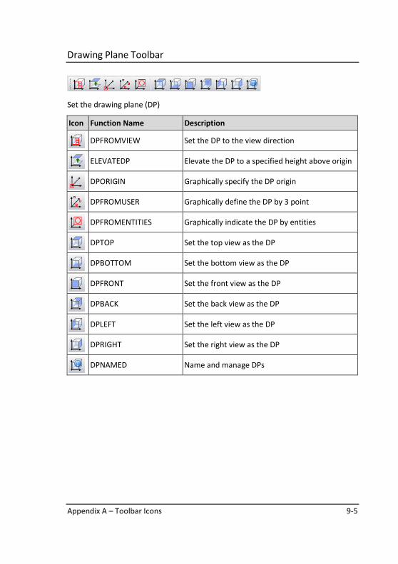
Appendix A – Toolbar Icons 9-5
Drawing Plane Toolbar
Set the drawing plane (DP)
Icon Function Name Description
DPFROMVIEW Set the DP to the view direction
ELEVATEDP Elevate the DP to a specified height above origin
DPORIGIN Graphically specify the DP origin
DPFROMUSER Graphically define the DP by 3 point
DPFROMENTITIES Graphically indicate the DP by entities
DPTOP Set the top view as the DP
DPBOTTOM Set the bottom view as the DP
DPFRONT Set the front view as the DP
DPBACK Set the back view as the DP
DPLEFT Set the left view as the DP
DPRIGHT Set the right view as the DP
DPNAMED Name and manage DPs

9-6 AllyCAD 2010
Geometry Toolbar
Functions to create geometry entities which are the equivalent of construction
lines.
Icon Function Name Description
GEOMCROSS Geometry cross
GEOMPARLINE Geometry line parallel to an existing line/circle
GEOMSLINE Geometry line at an angle
GEOMPPLINE Point to point geometry line
GEOMCIRCLE Geometry circle by centre and radius point
GEOMCIRCLERADDIAM Geometry circle by radius/diameter
GEOMCIRCLE3PNTS Geometry circle through 3 points
GEOMCIRCLETANL Geometry circle tangent to a line
GEOMCIRCLETANLL Geometry circle tangent to two lines
GEOMCIRCLETAN3L Geometry circle tangent to three lines
GEOMCIRCLETANLC Geometry circle tangent to a line and a circle
GEOMCIRCLETANC Geometry circle tangent to a circle
GEOMCIRCLETANCC Geometry circle tangent to two circles
GEOMLINETANC Geometry line tangent circle
GEOMLINETANCC Geometry line tangent 2 circles
GEOMPBISECT Geometry line perpendicular bisector
GEOMDIVIDEEQ Geometry divide equally

Appendix A – Toolbar Icons 9-7
Icon Function Name Description
MAKEGEOM Copy line/arc/circle as geometry
GEOMDELENT Delete geometry entity
GEOMDELALL Delete all geometry
GEOMTOGGLE Toggle display of geometry entities
Insert Toolbar
Insert blocks, tables, XRefs, images and OLE objects
Icon Function Name Description
INSERTBLOCK Insert block
INSERTTABLE Insert table
INSERTXREF Insert XREF
INSERTOLEOBJECT Insert external document
INSERTVIEWPORT Insert viewport
INSERTIMAGE Insert image
BLOCKSTATS Display block usage statistics
MANAGEXREFS View and manage external drawing references
MANAGEBLOCKS Block manager
IMAGES Image manager
PURGE Remove unused blocks, styles and duplicate
entities from the drawing
REMOVEDUP Remove duplicate entities from the drawing
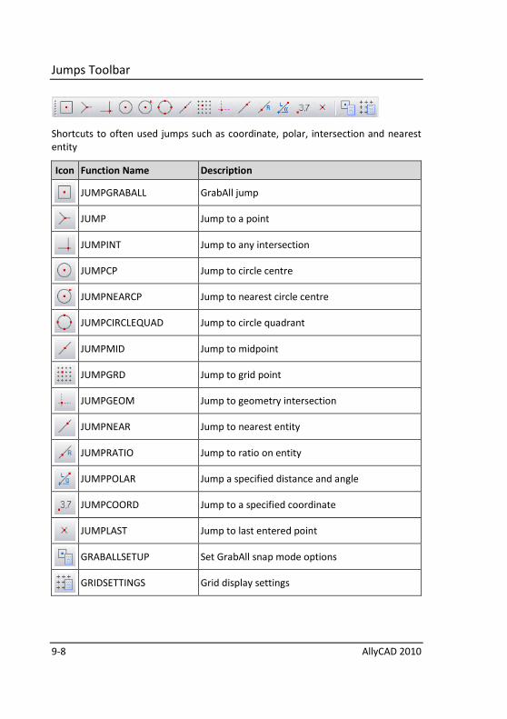
9-8 AllyCAD 2010
Jumps Toolbar
Shortcuts to often used jumps such as coordinate, polar, intersection and nearest
entity
Icon Function Name Description
JUMPGRABALL GrabAll jump
JUMP Jump to a point
JUMPINT Jump to any intersection
JUMPCP Jump to circle centre
JUMPNEARCP Jump to nearest circle centre
JUMPCIRCLEQUAD Jump to circle quadrant
JUMPMID Jump to midpoint
JUMPGRD Jump to grid point
JUMPGEOM Jump to geometry intersection
JUMPNEAR Jump to nearest entity
JUMPRATIO Jump to ratio on entity
JUMPPOLAR Jump a specified distance and angle
JUMPCOORD Jump to a specified coordinate
JUMPLAST Jump to last entered point
GRABALLSETUP Set GrabAll snap mode options
GRIDSETTINGS Grid display settings
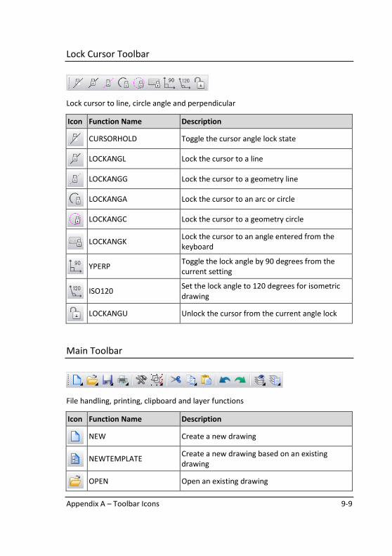
Appendix A – Toolbar Icons 9-9
Lock Cursor Toolbar
Lock cursor to line, circle angle and perpendicular
Icon Function Name Description
CURSORHOLD Toggle the cursor angle lock state
LOCKANGL Lock the cursor to a line
LOCKANGG Lock the cursor to a geometry line
LOCKANGA Lock the cursor to an arc or circle
LOCKANGC Lock the cursor to a geometry circle
LOCKANGK
Lock the cursor to an angle entered from the
keyboard
YPERP
Toggle the lock angle by 90 degrees from the
current setting
ISO120
Set the lock angle to 120 degrees for isometric
drawing
LOCKANGU Unlock the cursor from the current angle lock
Main Toolbar
File handling, printing, clipboard and layer functions
Icon Function Name Description
NEW Create a new drawing
NEWTEMPLATE
Create a new drawing based on an existing
drawing
OPEN Open an existing drawing
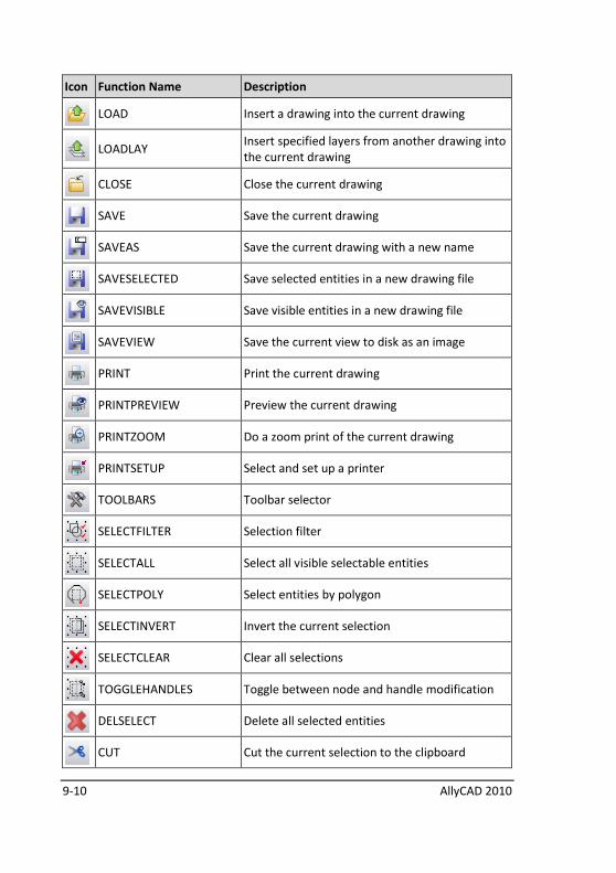
9-10 AllyCAD 2010
Icon Function Name Description
LOAD Insert a drawing into the current drawing
LOADLAY
Insert specified layers from another drawing into
the current drawing
CLOSE Close the current drawing
SAVE Save the current drawing
SAVEAS Save the current drawing with a new name
SAVESELECTED Save selected entities in a new drawing file
SAVEVISIBLE Save visible entities in a new drawing file
SAVEVIEW Save the current view to disk as an image
PRINT Print the current drawing
PRINTPREVIEW Preview the current drawing
PRINTZOOM Do a zoom print of the current drawing
PRINTSETUP Select and set up a printer
TOOLBARS Toolbar selector
SELECTFILTER Selection filter
SELECTALL Select all visible selectable entities
SELECTPOLY Select entities by polygon
SELECTINVERT Invert the current selection
SELECTCLEAR Clear all selections
TOGGLEHANDLES Toggle between node and handle modification
DELSELECT Delete all selected entities
CUT Cut the current selection to the clipboard
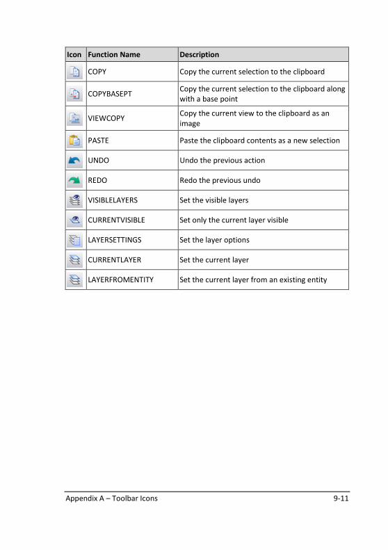
Appendix A – Toolbar Icons 9-11
Icon Function Name Description
COPY Copy the current selection to the clipboard
COPYBASEPT
Copy the current selection to the clipboard along
with a base point
VIEWCOPY
Copy the current view to the clipboard as an
image
PASTE Paste the clipboard contents as a new selection
UNDO Undo the previous action
REDO Redo the previous undo
VISIBLELAYERS Set the visible layers
CURRENTVISIBLE Set only the current layer visible
LAYERSETTINGS Set the layer options
CURRENTLAYER Set the current layer
LAYERFROMENTITY Set the current layer from an existing entity
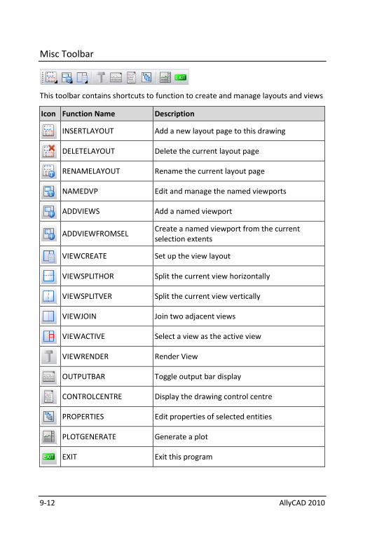
9-12 AllyCAD 2010
Misc Toolbar
This toolbar contains shortcuts to function to create and manage layouts and views
Icon Function Name Description
INSERTLAYOUT Add a new layout page to this drawing
DELETELAYOUT Delete the current layout page
RENAMELAYOUT Rename the current layout page
NAMEDVP Edit and manage the named viewports
ADDVIEWS Add a named viewport
ADDVIEWFROMSEL
Create a named viewport from the current
selection extents
VIEWCREATE Set up the view layout
VIEWSPLITHOR Split the current view horizontally
VIEWSPLITVER Split the current view vertically
VIEWJOIN Join two adjacent views
VIEWACTIVE Select a view as the active view
VIEWRENDER Render View
OUTPUTBAR Toggle output bar display
CONTROLCENTRE Display the drawing control centre
PROPERTIES Edit properties of selected entities
PLOTGENERATE Generate a plot
EXIT Exit this program
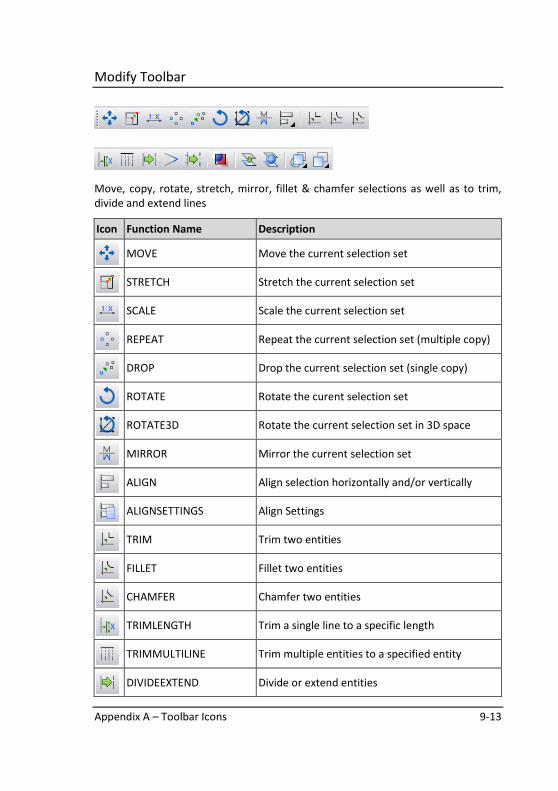
Appendix A – Toolbar Icons 9-13
Modify Toolbar
Move, copy, rotate, stretch, mirror, fillet & chamfer selections as well as to trim,
divide and extend lines
Icon Function Name Description
MOVE Move the current selection set
STRETCH Stretch the current selection set
SCALE Scale the current selection set
REPEAT Repeat the current selection set (multiple copy)
DROP Drop the current selection set (single copy)
ROTATE Rotate the curent selection set
ROTATE3D Rotate the current selection set in 3D space
MIRROR Mirror the current selection set
ALIGN Align selection horizontally and/or vertically
ALIGNSETTINGS Align Settings
TRIM Trim two entities
FILLET Fillet two entities
CHAMFER Chamfer two entities
TRIMLENGTH Trim a single line to a specific length
TRIMMULTILINE Trim multiple entities to a specified entity
DIVIDEEXTEND Divide or extend entities
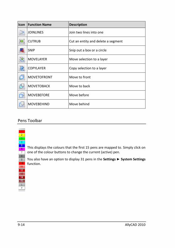
9-14 AllyCAD 2010
Icon Function Name Description
JOINLINES Join two lines into one
CUTRUB Cut an entity and delete a segment
SNIP Snip out a box or a circle
MOVELAYER Move selection to a layer
COPYLAYER Copy selection to a layer
MOVETOFRONT Move to front
MOVETOBACK Move to back
MOVEBEFORE Move before
MOVEBEHIND Move behind
Pens Toolbar
This displays the colours that the first 15 pens are mapped to. Simply click on
one of the colour buttons to change the current (active) pen.
You also have an option to display 31 pens in the Settings ► System Settings
function.
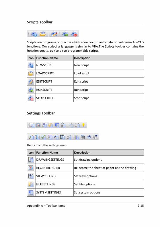
Appendix A – Toolbar Icons 9-15
Scripts Toolbar
Scripts are programs or macros which allow you to automate or customise AllyCAD
functions. Our scripting language is similar to VBA.The Scripts toolbar contains the
function create, edit and run programmable scripts.
Icon Function Name Description
NEWSCRIPT New script
LOADSCRIPT Load script
EDITSCRIPT Edit script
RUNSCRIPT Run script
STOPSCRIPT Stop script
Settings Toolbar
Items from the settings menu
Icon Function Name Description
DRAWINGSETTINGS Set drawing options
RECENTREPAPER Re-centre the sheet of paper on the drawing
VIEWSETTINGS Set view options
FILESETTINGS Set file options
SYSTEMSETTINGS Set system options
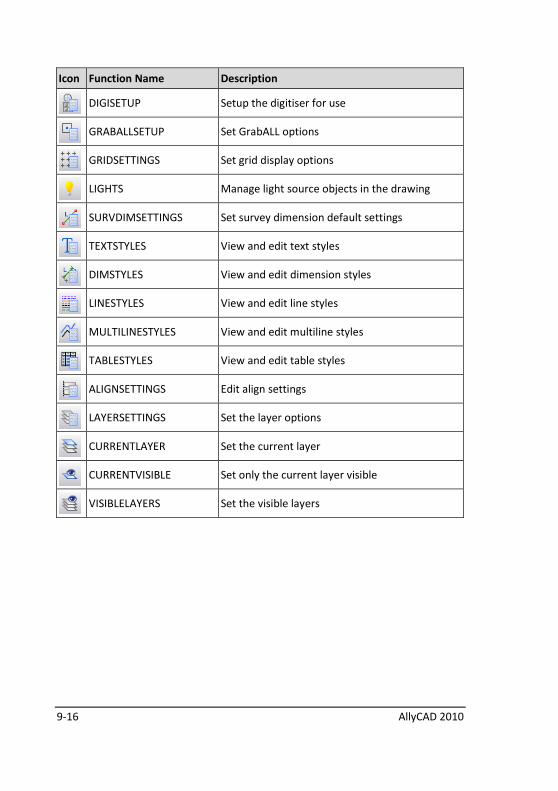
9-16 AllyCAD 2010
Icon Function Name Description
DIGISETUP Setup the digitiser for use
GRABALLSETUP Set GrabALL options
GRIDSETTINGS Set grid display options
LIGHTS Manage light source objects in the drawing
SURVDIMSETTINGS Set survey dimension default settings
TEXTSTYLES View and edit text styles
DIMSTYLES View and edit dimension styles
LINESTYLES View and edit line styles
MULTILINESTYLES View and edit multiline styles
TABLESTYLES View and edit table styles
ALIGNSETTINGS Edit align settings
LAYERSETTINGS Set the layer options
CURRENTLAYER Set the current layer
CURRENTVISIBLE Set only the current layer visible
VISIBLELAYERS Set the visible layers
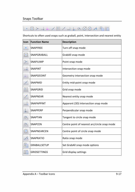
Appendix A – Toolbar Icons 9-17
Snaps Toolbar
Shortcuts to often used snaps such as graball, point, intersection and nearest entity
Icon Function Name Description
SNAPFREE Turn off snap mode
SNAPGRABALL GrabAll snap mode
SNAPJUMP Point snap mode
SNAPINT Intersection snap mode
SNAPGEOINT Geometry intersection snap mode
SNAPMID Entity mid-point snap mode
SNAPGRID Grid snap mode
SNAPNEAR Nearest entity snap mode
SNAPAPPINT Apparent (3D) intersection snap mode
SNAPPERP Perpendicular snap mode
SNAPTAN Tangent to circle snap mode
SNAPCEN Centre point of nearest arc/circle snap mode
SNAPNEARCEN Centre point of circle snap mode
SNAPRATIO Ratio snap mode
GRABALLSETUP Set GrabAll snap mode options
GRIDSETTINGS Grid display settings
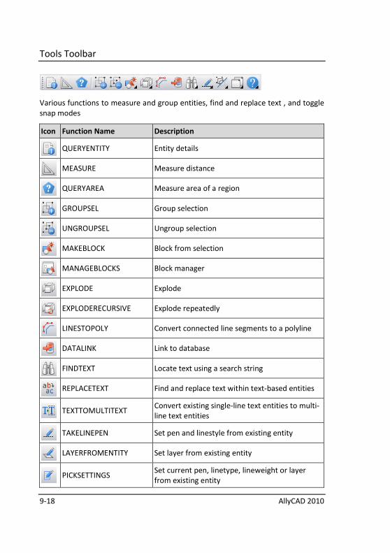
9-18 AllyCAD 2010
Tools Toolbar
Various functions to measure and group entities, find and replace text , and toggle
snap modes
Icon Function Name Description
QUERYENTITY Entity details
MEASURE Measure distance
QUERYAREA Measure area of a region
GROUPSEL Group selection
UNGROUPSEL Ungroup selection
MAKEBLOCK Block from selection
MANAGEBLOCKS Block manager
EXPLODE Explode
EXPLODERECURSIVE Explode repeatedly
LINESTOPOLY Convert connected line segments to a polyline
DATALINK Link to database
FINDTEXT Locate text using a search string
REPLACETEXT Find and replace text within text-based entities
TEXTTOMULTITEXT
Convert existing single-line text entities to multi-
line text entities
TAKELINEPEN Set pen and linestyle from existing entity
LAYERFROMENTITY Set layer from existing entity
PICKSETTINGS
Set current pen, linetype, lineweight or layer
from existing entity
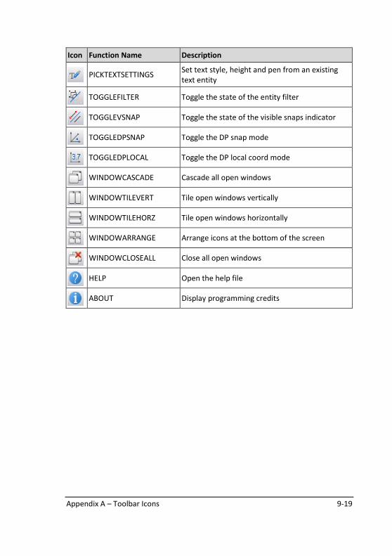
Appendix A – Toolbar Icons 9-19
Icon Function Name Description
PICKTEXTSETTINGS
Set text style, height and pen from an existing
text entity
TOGGLEFILTER Toggle the state of the entity filter
TOGGLEVSNAP Toggle the state of the visible snaps indicator
TOGGLEDPSNAP Toggle the DP snap mode
TOGGLEDPLOCAL Toggle the DP local coord mode
WINDOWCASCADE Cascade all open windows
WINDOWTILEVERT Tile open windows vertically
WINDOWTILEHORZ Tile open windows horizontally
WINDOWARRANGE Arrange icons at the bottom of the screen
WINDOWCLOSEALL Close all open windows
HELP Open the help file
ABOUT Display programming credits
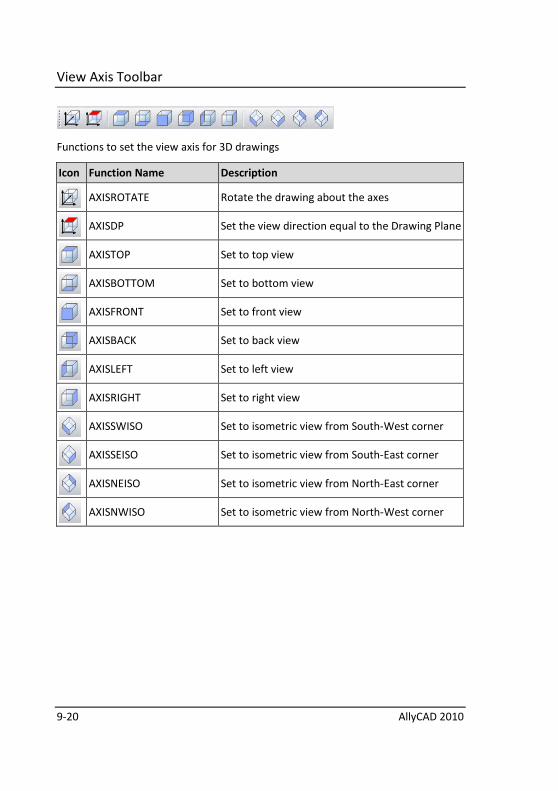
9-20 AllyCAD 2010
View Axis Toolbar
Functions to set the view axis for 3D drawings
Icon Function Name Description
AXISROTATE Rotate the drawing about the axes
AXISDP Set the view direction equal to the Drawing Plane
AXISTOP Set to top view
AXISBOTTOM Set to bottom view
AXISFRONT Set to front view
AXISBACK Set to back view
AXISLEFT Set to left view
AXISRIGHT Set to right view
AXISSWISO Set to isometric view from South-West corner
AXISSEISO Set to isometric view from South-East corner
AXISNEISO Set to isometric view from North-East corner
AXISNWISO Set to isometric view from North-West corner
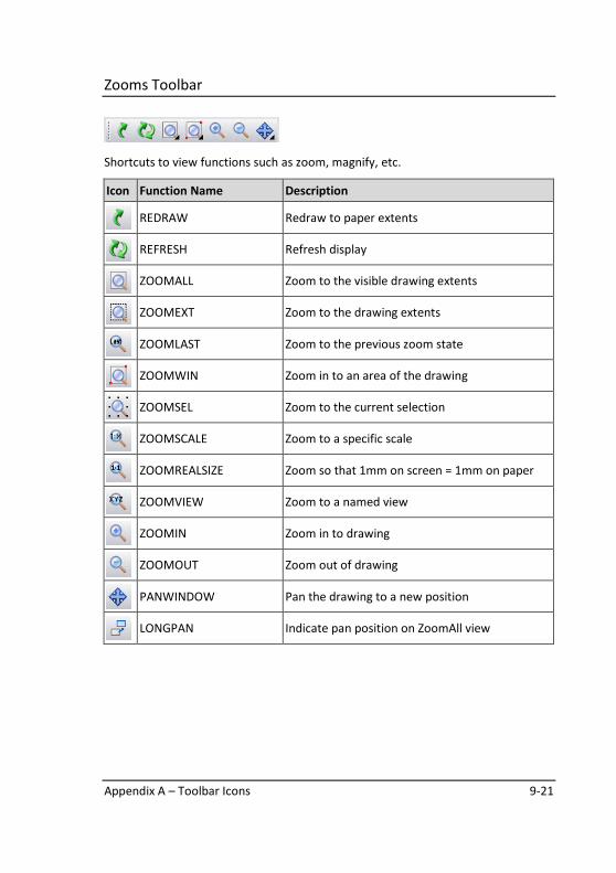
Appendix A – Toolbar Icons 9-21
Zooms Toolbar
Shortcuts to view functions such as zoom, magnify, etc.
Icon Function Name Description
REDRAW Redraw to paper extents
REFRESH Refresh display
ZOOMALL Zoom to the visible drawing extents
ZOOMEXT Zoom to the drawing extents
ZOOMLAST Zoom to the previous zoom state
ZOOMWIN Zoom in to an area of the drawing
ZOOMSEL Zoom to the current selection
ZOOMSCALE Zoom to a specific scale
ZOOMREALSIZE Zoom so that 1mm on screen = 1mm on paper
ZOOMVIEW Zoom to a named view
ZOOMIN Zoom in to drawing
ZOOMOUT Zoom out of drawing
PANWINDOW Pan the drawing to a new position
LONGPAN Indicate pan position on ZoomAll view
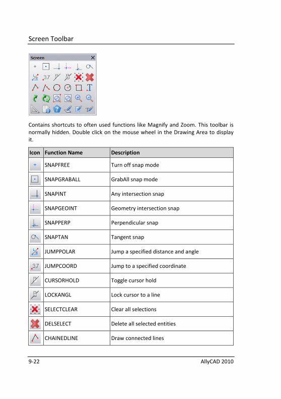
9-22 AllyCAD 2010
Screen Toolbar
Contains shortcuts to often used functions like Magnify and Zoom. This toolbar is
normally hidden. Double click on the mouse wheel in the Drawing Area to display
it.
Icon Function Name Description
SNAPFREE Turn off snap mode
SNAPGRABALL GrabAll snap mode
SNAPINT Any intersection snap
SNAPGEOINT Geometry intersection snap
SNAPPERP Perpendicular snap
SNAPTAN Tangent snap
JUMPPOLAR Jump a specified distance and angle
JUMPCOORD Jump to a specified coordinate
CURSORHOLD Toggle cursor hold
LOCKANGL Lock cursor to a line
SELECTCLEAR Clear all selections
DELSELECT Delete all selected entities
CHAINEDLINE Draw connected lines
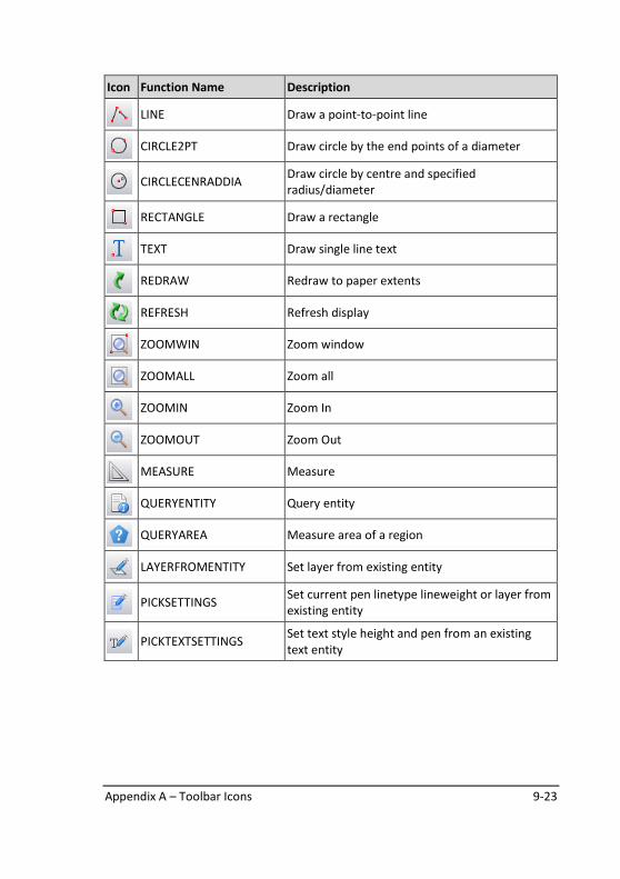
Appendix A – Toolbar Icons 9-23
Icon Function Name Description
LINE Draw a point-to-point line
CIRCLE2PT Draw circle by the end points of a diameter
CIRCLECENRADDIA
Draw circle by centre and specified
radius/diameter
RECTANGLE Draw a rectangle
TEXT Draw single line text
REDRAW Redraw to paper extents
REFRESH Refresh display
ZOOMWIN Zoom window
ZOOMALL Zoom all
ZOOMIN Zoom In
ZOOMOUT Zoom Out
MEASURE Measure
QUERYENTITY Query entity
QUERYAREA Measure area of a region
LAYERFROMENTITY Set layer from existing entity
PICKSETTINGS
Set current pen linetype lineweight or layer from
existing entity
PICKTEXTSETTINGS
Set text style height and pen from an existing
text entity
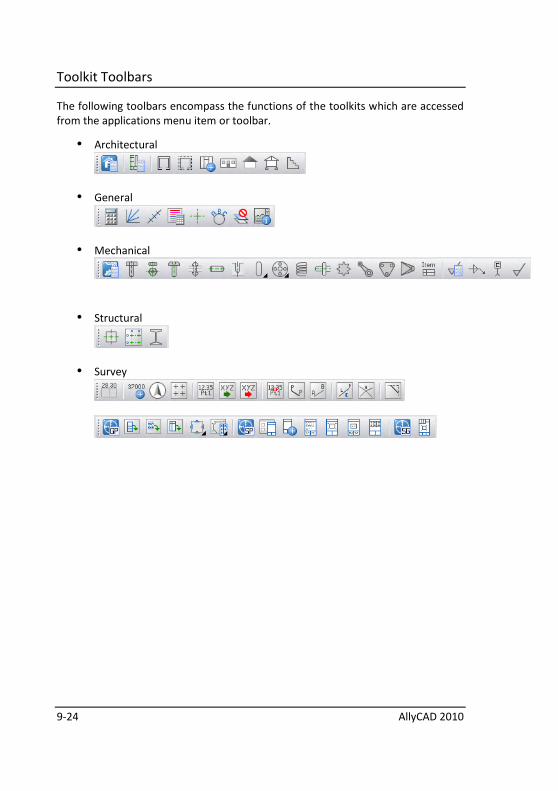
9-24 AllyCAD 2010
Toolkit Toolbars
The following toolbars encompass the functions of the toolkits which are accessed
from the applications menu item or toolbar.
• Architectural
• General
• Mechanical
• Structural
• Survey
Index
A Arrow Keys ....................................................................................................... 4-2, 4-5
C CAD Folder .............................................................................................................. 2-2
Control Bar .............................................................................................................. 3-6
Cursor
unlocking permanently ....................................................................................... 4-5
Customising AllyCAD ............................................................................................... 2-5
D Default accelerator keys ....................................................................................... 3-37
F Files Installed by the CAD ....................................................................................... 2-2
Fill Geom ................................................................................................................. 5-3
Folders Installed by the CAD ................................................................................... 2-2
G Geometry
available constructions ....................................................................................... 5-2
deleting ............................................................................................................... 5-7
inking in .............................................................................................................. 5-3
jumping and snapping to .................................................................................... 5-4
projecting from existing lines / arcs .................................................................... 5-4
properties ........................................................................................................... 5-2
switching on and off ........................................................................................... 5-7
tan snap mode .................................................................................................... 5-6
tracing over ......................................................................................................... 5-3
Geometry Trace-Over ............................................................................................. 5-3
Grid ......................................................................................................................... 4-9
jumping or snapping to ....................................................................................... 4-9
Guest Sub-folder ..................................................................................................... 2-3
H Home (Screen Centre) ............................................................................................ 4-5
I Icons ..................................................................................................................... 3-12
Installation .............................................................................................................. 2-2
J Jumps ...................................................................................................................... 4-6
difference between jumps and snap modes ....................................................... 4-6
K Keyboard ............................................................................................................... 3-37
Editing ............................................................................................................... 3-39
File Handling ...................................................................................................... 3-41
Jumps ................................................................................................................ 3-37
Navigation ......................................................................................................... 3-39
Snaps ................................................................................................................. 3-38
L Layer Display ......................................................................................................... 3-11
Layers
changing ............................................................................................................ 3-11
current .............................................................................................................. 3-11
Learning AllyCAD ..................................................................................................... 2-4
Line Type
current .............................................................................................................. 3-11
setting ............................................................................................................... 3-11
Line Type Display ................................................................................................... 3-11
Lines
drawing orthogonal ............................................... see Lock Cursor; Move Distance
Lock Cursor .............................................................................................................. 4-4
see also Move Distance ....................................................................................... 4-4
M Make Geometry ...................................................................................................... 5-4
Minimum Requirements ......................................................................................... 2-1
Mouse ................................................................................................................... 3-42
Move to Coordinates .............................................................................................. 4-5
Moving
nudging ............................................................................................................... 4-2
Moving the Cursor
to a specific point ............................................................... see Jumps; Snap Modes
N Nudge ...................................................................................................................... 4-2
P Pen Selection ........................................................................................................ 3-10
Polar Move ............................................................................................................. 4-3
Program Home Folder ............................................................................................ 2-2
Prompt Area ........................................................................................................... 3-6
R Reference manual ................................................................................................... 1-2
S Screen Centre, jumping to ...................................................................................... 4-5
Screen layout .......................................................................................................... 3-2
Snap Modes ..................................................................................................... 4-6, 4-8
difference between jumps and snap modes ....................................................... 4-6
Symbol Sub-folder .................................................................................................. 2-2
System Requirements ............................................................................................. 2-1
T Tangent (Snap Mode)
using with geometry ........................................................................................... 5-6
Things You Should Know ......................................................................................... 2-4
Toolbar.................................................................................................................. 3-12
U Unlock (Cursor) ....................................................................................................... 4-5
Users Sub-folder ..................................................................................................... 2-3
X X, Y Coordinates .................................................................................. see Coordinates