alpha modular switched mode rectifier...
TRANSCRIPT

Your Power Solutions Partner
Alpha Modular Switched Mode Rectifier SystemRectifier Models: Cordex HP CXRF 48-2.0kW
Cordex CXRF 48-1.8kW
Installation and Operation ManualPart #030-807-J0Effective 05/2011
member of The Group™


Modular Switched Mode Rectifier SystemModels: Cordex (CXRF) 48V-1.8kW &
Cordex HP (CXRF) 48V-2.0kW
For technical support, contact Alpha Technologies:
Canada and USA: 1-888-462-7487International: +1-604-436-5547
Email: [email protected]
CopyrightCopyright © 2011 Alpha Technologies Ltd. All rights reserved. Alpha is a registered trademark of Alpha Technolo-gies.
No part of this documentation shall be reproduced, stored in a retrieval system, translated, transcribed, or trans-mitted in any form or by any means manual, electric, electronic, electromechanical, chemical, optical, or other-wise without prior explicit written permission from Alpha Technologies.
This document, the software it describes, and the information and know-how they contain constitute the propri-etary, confidential and valuable trade secret information of Alpha Technologies, and may not be used for any unauthorized purpose, or disclosed to others without the prior written permission of Alpha Technologies.
The material contained in this document is for information only and is subject to change without notice. While reasonable efforts have been made in the preparation of this document to assure its accuracy, Alpha Technolo-gies assumes no liability resulting from errors or omissions in this document, or from the use of the information contained herein. Alpha Technologies reserves the right to make changes in the product design without reserva-tion and without notification to its users.
Alpha shall not be held liable for any damage or injury involving its enclosures, power supplies, generators, batteries, or other hardware if used or operated in any manner or subject to any condition inconsistent with its intended purpose, or if installed or oper-ated in an unapproved manner, or improperly maintained.
Photographs contained in this manual are for illustrative purposes only. These photo-graphs may not match your installation.
NOTE:
Operator is cautioned to review the drawings and illustrations contained in this manual before proceeding. If there are questions regarding the safe operation of this powering system, contact Alpha Technologies or your nearest Alpha representative.
NOTE:
NOTE:

030-807-J0 Rev A2
Table of Contents
1. Safety ....................................................................................................................................5
1.1 Safety Symbols .......................................................................................................................... 5
1.2 Mechanical Safety ...................................................................................................................... 5
1.3 Electrical Safety ......................................................................................................................... 6
1.4 Battery Safety ............................................................................................................................ 6
2. Introduction ...........................................................................................................................7
2.1 Scope of the Manual .................................................................................................................. 7
2.2 Product Overview ....................................................................................................................... 7
2.3 Part Numbers and List Options .................................................................................................. 8
3. Features ..............................................................................................................................10
3.1 Controller ................................................................................................................................. 10
3.2 Front Panel .............................................................................................................................. 10
3.3 Rectifier Rear Panel ................................................................................................................. 12
3.4 True Module Fail Alarm ............................................................................................................ 12
3.5 Heat Dissipation ....................................................................................................................... 12
3.6 Over Temperature Protection ................................................................................................... 12
3.7 Wide AC Range ....................................................................................................................... 12
3.8 AC Inrush/Transient Suppression ............................................................................................ 12
3.9 Soft Start .................................................................................................................................. 12
3.10 Start Delay ............................................................................................................................. 13
3.11 Current Limit/Short Circuit Protection ..................................................................................... 13
3.12 Power Limiting ....................................................................................................................... 13
3.13 High Voltage Shutdown (HVSD) ............................................................................................ 13
3.14 Battery Eliminator Operation .................................................................................................. 13
4. CXCM2 and CXCI Features................................................................................................14
4.1 System Controller Front Panel ................................................................................................. 14
4.2 Analog Input Channels ............................................................................................................. 16
4.3 Digital Input Channels .............................................................................................................. 16
4.4 Alarm and Control Output Relays ............................................................................................ 16

3030-807-J0 Rev A
4.5 Network Connection and Remote Communications ................................................................ 16
5. Inspection............................................................................................................................17
5.1 Packing Materials ..................................................................................................................... 17
5.2 Check for Damage ................................................................................................................... 17
5.3 General Receipt of Shipment ................................................................................................... 17
6. Installation ...........................................................................................................................18
6.1 Safety Precautions ................................................................................................................... 18
6.2 Tools Required ......................................................................................................................... 18
6.3 Power System Assembly and Mounting ................................................................................... 19
6.4 Shelf Preparation/Mounting ..................................................................................................... 19
6.5 Rectifier Module Insertion/Removal ......................................................................................... 19
6.6 Battery Installation ................................................................................................................... 21
7. Wiring ..................................................................................................................................23
7.1 Power System Chassis Ground and DC Ground Reference ................................................... 23
7.2 AC Feeder Protection/Sizing .................................................................................................... 23
7.3 AC Input Connections .............................................................................................................. 23
7.4 DC Output Connections ........................................................................................................... 24
7.5 CAN Serial Ports ...................................................................................................................... 25
7.6 Network Connection and Remote Communications via CXC .................................................. 27
8. System Startup ...................................................................................................................28
8.1 Check System Connections ..................................................................................................... 28
8.2 Verify AC and Power the Rectifier Shelf ................................................................................... 28
8.3 Check Battery Polarity and Connect ........................................................................................ 28
8.4 CXC Reset ............................................................................................................................... 28
9. Operation ............................................................................................................................30
9.1 Main Rectifier States ................................................................................................................ 30
9.2 Main Rectifier Modes ............................................................................................................... 31
9.3 Factory Ranges and Defaults .................................................................................................. 32
10. Maintenance .....................................................................................................................33
10.1 Fan Replacement ................................................................................................................... 33

030-807-J0 Rev A4
10.2 CXRF 1.8kW Rectifier Fan Replacement ............................................................................. 36
10.3 MOV Replacement ................................................................................................................. 36
10.4 CXCI or CXCM2 Replacement Procedure ............................................................................. 36
11. Alpha Conventions ............................................................................................................38
11.1 Numbering System ................................................................................................................. 38
11.2 Acronyms and Definitions ....................................................................................................... 38
12. Warranty and Service Information ....................................................................................39

5030-807-J0 Rev A
1. Safety
SAVE THESE INSTRUCTIONS: This manual contains important safety instructions that must be followed during the installation, servicing, and maintenance of the product. Keep it in a safe place. Review the drawings and illustrations contained in this manual before proceeding. If there are any questions regarding the safe installation or operation of this product, contact Alpha Technologies or the nearest Alpha rep-resentative. Save this document for future reference.
1.1 Safety SymbolsTo reduce the risk of injury or death, and to ensure the continued safe operation of this product, the following symbols have been placed throughout this manual. Where these symbols appear, use extra care and attention.
The use of ATTENTION indicates specific regulatory/code requirements that may affect the placement of equipment and /or installation procedures.
WARNING!
WARNING presents safety information to PREVENT INJURY OR DEATH to personnel. Warnings are indicated by a shock hazard icon, the word WARNING, and a rule beneath which the information appears.
CAUTION!
CAUTION indicates safety information intended to PREVENT DAMAGE to material or equipment. Cautions are designated with a yellow warning triangle, the word CAUTION, and a rule beneath which the information appears.
NOTE:A NOTE provides additional information to help complete a specific task or procedure. Notes are designated with a checkmark, the word NOTE, and a rule beneath which the information appears
HOT!
The use of HOT presents safety information to PREVENT BURNS to the technician or user.
1.2 Mechanical Safety• Keep hands and tools clear of fans. Fans are thermostatically controlled and switch on automatically.
• Power supplies can reach extreme temperatures under load.
• Use caution around sheet metal components and sharp edges.

030-807-J0 Rev A6
1.3 Electrical Safety
WARNING!
WARNING!
WARNING!
Before working with any live battery or power system, follow these precautions:
a. Remove all metallic jewelry, such as watches, rings, metal rimmed glasses, or necklaces.
b. Wear safety glasses with side shields at all times during the installation.
c. Use OSHA approved insulated hand tools.
Lethal voltages are present within the power system. Always assume that an electrical connection or conductor is energized. Check the circuit with a voltmeter with respect to the grounded portion of the enclosure (both AC and DC) before performing any installa-tion or removal procedure.
• Do not work alone under hazardous conditions.
• A licensed electrician is required to install permanently wired equipment. Input voltages can range up to 240 Vac. Ensure that the utility power is disconnected and locked out before performing any installation or removal procedure.
• Ensure that no liquids or wet clothes come into contact with internal components.
• Hazardous electrically live parts inside this unit are energized from the batteries even when the AC input power is disconnected.
1.4 Battery Safety• Servicing and connection of batteries must be performed by, or under the direct supervision of, personnel
knowledgeable of batteries and the required safety precautions.
• Always wear eye protection, rubber gloves, and a protective vest when working near batteries. Remove all metallic objects from your hands and neck.
• Use OSHA approved insulated hand tools. Do not rest tools on top of batteries.
• Batteries contain or emit chemicals known to cause cancer and birth defects or other reproductive harm. Battery post terminals and related accessories contain lead and lead compounds. Wash your hands after handling batteries.
Follow battery manufacturer’s safety recommendations when working around battery systems. Do not smoke or introduce an open flame when batteries (especially vented batteries) are charging. When charging, batteries vent hydrogen gas, which can ex-plode.
• Batteries are hazardous to the environment and should be disposed at a recycling facility. Consult the bat-tery manufacturer for recommended local authorized recyclers.
Hazardous voltages are present at the input of power systems. The DC output from rec-tifiers and batteries, though not dangerous in voltage, has a high short-circuit current capacity that may cause severe burns and electrical arcing.
7030-807-J0 Rev A
2. Introduction
2.1 Scope of the ManualThis instruction manual explains the installation, interconnection, and operation of the Alpha Modular Switched Mode Rectifier System for the following rectifier models:
• Cordex (CXRF) HP 48-2.0kW
• Cordex (CXRF) 48-1.8kW
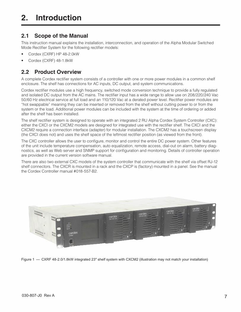
2.2 Product OverviewA complete Cordex rectifier system consists of a controller with one or more power modules in a common shelf enclosure. The shelf has connections for AC inputs, DC output, and system communications.
Cordex rectifier modules use a high frequency, switched mode conversion technique to provide a fully regulated and isolated DC output from the AC mains. The rectifier input has a wide range to allow use on 208/220/240 Vac 50/60 Hz electrical service at full load and an 110/120 Vac at a derated power level. Rectifier power modules are “hot swappable” meaning they can be inserted or removed from the shelf without cutting power to or from the system or the load. Additional power modules can be included with the system at the time of ordering or added after the shelf has been installed.
The shelf rectifier system is designed to operate with an integrated 2 RU Alpha Cordex System Controller (CXC): either the CXCI or the CXCM2 models are designed for integrated use with the rectifier shelf. The CXCI and the CXCM2 require a connection interface (adapter) for modular installation. The CXCM2 has a touchscreen display (the CXCI does not) and uses the shelf space of the leftmost rectifier position (as viewed from the front).
The CXC controller allows the user to configure, monitor and control the entire DC power system. Other features of the unit include temperature compensation, auto equalization, remote access, dial-out on alarm, battery diag-nostics, as well as Web server and SNMP support for configuration and monitoring. Details of controller operation are provided in the current version software manual.
There are also two external CXC models of the system controller that communicate with the shelf via offset RJ-12 shelf connectors. The CXCR is mounted in a rack and the CXCP is (factory) mounted in a panel. See the manual the Cordex Controller manual #018-557-B2.
Figure 1 — CXRF 48-2.0/1.8kW integrated 23" shelf system with CXCM2 (illustration may not match your installation)

030-807-J0 Rev A8
2.3 Part Numbers and List OptionsThe product, options, and accessories can be ordered by using the following part numbers:
Table A — Options and accessoriesDescription Part Number
CXRF 48-2.0/1.8kW 23" shelf for systems up to 10kW (pre-RoHS 030-747-20) 030-807-20
Basic unit (see controller options) equipped to receive up to five 48-2.0/1.8 kW rectifiers *List 0
48 Vdc system *List 2
6" offset mounting List 24
Charcoal finish with white (contrasting) silkscreen *List 56
AC inputs, Molex mini-fit List 83
AC inputs, terminal blocks List 84
AC line cords, Molex mini-fit, 3m List 89
Rectifier blank plate List 90
CXCI controller blank plate *List 91
Rear cover, Kydex List 92
CXCI controller List 99
CXRF 48-2.0/1.8kW 19” shelf for systems up to 8kW (pre-RoHS 030-749-20) 030-809-20
Basic unit (see controller options) equipped to receive up to four 48-2.0/1.8 kW rectifiers *List 0
48 Vdc system *List 2
6" offset mounting for 19" rack List 19
6" offset mounting for 23" rack List 24
Charcoal finish with white (contrasting) silkscreen *List 56
AC input individual feed terminal blocks *List 84
AC input dual feed terminal blocks List 85
Rectifier blank plate List 90
CXCI controller blank plate *List 91
Rear cover, Kydex List 92
CXCI controller List 99
Cordex 48-1.8kW rectifier power module, 208-240 Vac input (pre-RoHS 010-580-20) 010-602-20
Basic module *List 0
Charcoal finish with white (contrasting) silkscreen *List 56
Cordex HP 48-2.0kW rectifier power module 010-622-20
Basic module *List 0
Plastic front panel, black *List 58
LED mounting option 1 *List 85
LED mounting option 2 List 86
CXCM2 controller (takes the space of CXCI and one rectifier position) (pre-RoHS 018-573-20) 018-588-20
Basic module *List 0
48 Vdc system *List 2
Standard temperature List 40
Extended temperature *List 42
Charcoal finish with white (contrasting) silkscreen *List 56

9030-807-J0 Rev A
Table A — Options and accessoriesDescription Part Number
Expanded Flash memory (8MB) *List 110
Four bi-voltage inputs *List 126
Second current shunt input *List 127
CXCM2 I/O terminal block kit (for external connections) **036-200-20-000
CXCI I/O terminal block kit (for external connections) **036-201-20-000
Fan assembly, (spare for CXRF 48-1.8kW) 747-362-20
MOV assembly, (spare for CXRF 48-1.8kW) 707-556-20
Replacement CXCI controller 747-505-20
Fan assembly, spare for Cordex 48-2kW Rectifier 7400012-001
Replacement CXCI controller 747-427-20-000
Cordex DC Modem with Alpha cable 018-585-20-040
*Default Options
**See drawings at the rear of this manual.
The above information is valid at the time of publication. Consult factory for up-to-date ordering information.

030-807-J0 Rev A10
3. Features
3.1 ControllerAll alarming and control of Cordex rectifiers is accomplished with a CXC via a CAN bus. The Cordex rectifier shelves provide connections for serial communications with other rectifier shelves as well as supervisory and control panels.
3.2 Front PanelFigure 2 and Figure 3 show the front panels of the two rectifier options of the switched mode rectifier system.
3.2.1 LED LIGHTSThe front panel LEDs show:
• Rectifier status summary
• Rectifier software upgrade in progress indication
• Locate module pattern to locate a specific module under CXC control
Figure 2 — Cordex HP48-2kW
LEDs
Lever
Figure 3 — Cordex 48-1.8kW
LEDs
Thumbscrew Latch
Handle
11030-807-J0 Rev A
Rectifier status summary
The three LEDs on the front panel show the rectifier alarm, communication fail, and rectifier on/off status.
AC ON The top green LED illuminates when the AC input voltage is within its allowable range. The LED flashes (~2Hz) when input voltage is outside the allowable range. The AC input voltage is invalid if the AC Mains Low or AC Mains High alarm is active. The LED extinguishes if the AC input fails.
DC ON The middle green LED illuminates when the rectifier is delivering power to the load. The LED flashes when communication is lost. The LED extinguishes when the rectifier is off, e.g., when commanded by the CXC.
ALARM The bottom red LED illuminates during an active Module Fail alarm if the module is unable to source power as a result of any of the following conditions:
Output fuse blown AC mains input fail Module fail (ramp test fail)High voltage (OVP) shutdown Thermal shutdown Local shutdownUPF fail No output power Fan fail
The LED flashes (~2Hz) when a minor alarm is detected if the module's output capability has been reduced or a minor component failure is detected during the following conditions:
VAC meter fail AC foldback Remote equalizeFan fail Low output voltage High output voltageCurrent limit (programmable option) Power limit (programmable option) High temperature foldbackTemperature sense fail Soft start operation Communications lost
The LED remains extinguished in the absence of an alarm. If the unit output is not connected to a battery or parallel rectifier, the LED extinguishes if no AC power is present.
LED Activity During Software Upload
When a rectifier software upload is in progress, the LEDs behave in a distinctly different way to indicate that new rectifier software is being transferred from the CXC.
When a rectifier data transfer is in progress, all three LEDs flash in a sequence lasting 1.5 seconds. After the last LED has illuminated, the sequence will repeat starting with the first LED.
LED Activity During Locate Module Command from CXC
When the Locate Module command has been received from the CXC, the LEDs behave in another distinct fash-ion that allows the rectifier to be easily identified among adjacent rectifiers.
This state is entered when commanded by the CXC. The LEDs flash in a ping-pong pattern, repeating every two-seconds. During a ping-pong pattern, each LED illuminates sequentially. After the last LED is illuminated, each LED is illuminated in a reverse sequence. When the first LED is illuminated, the pattern repeats. This effect makes it appear that the light bounces between the first and last LED.
3.2.2 Mechanical
Cordex HP 48-2.0kW
Figure 2 shows the lever that is incorporated into the front panel to help remove the rectifier from the shelf. A screwdriver is needed to unlock the lever from its closed position. See section 6.5.2.
Cordex 48-1.8kW
Figure 3 shows the thumbscrew latch that secures the rectifier into the shelf. During normal operation the rectifier is locked into position. A handle (or grip) is incorporated into the front panel to facilitate the removal of the rectifier from the shelf. No special tools are required. See section 6.5.3.
030-807-J0 Rev A12
3.5 Heat DissipationEach rectifier module is equipped with one front-mounted fan. The fan runs when temperature is above 0ºC (32ºF). The air flow is front-to-rear with the exhaust air exiting at the back. The fan is variable speed. The speed is determined by the heatsink temperature and the load.
3.6 Over Temperature ProtectionEach rectifier module is protected against an excessive increase in temperature caused by a component fail-ure or a cooling airflow blockage. During over-temperature conditions, the rectifier limits the output power and the output current. If the temperature continues to increase, a shutdown of the rectifier is initiated. The rectifier restarts automatically when the temperature returns to a safe level.
3.7 Wide AC RangeA minor alarm is generated when the AC input voltage drops below its allowable limit. The rectifier output power is reduced linearly between 187 Vac and 90 Vac. At 90 Vac, the unit delivers derated output power that is more than 33% of the rated output power.
Below 90 Vac, the module shuts down and restarts only when the AC voltage is greater than 95 Vac. The actual-restart voltage depends on the load current. A reduced load current may allow a restart input voltage as low as 100 Vac.
For voltages above 277 Vac, the power factor and total harmonic distortion may be derated. Up to 312 Vac (320 Vac for the 1.8 rectifier), the rectifier is operational and will not suffer any damage.
3.8 AC Inrush/Transient SuppressionTo prevent a surge on the AC input line, the inrush current of a rectifier module is limited to the full load steady state line current. Modules are also protected from input lightning and transient surges in accordance with IEEE/ANSI C62.41 Category B3 standards.
3.9 Soft StartA soft start feature is used to eliminate an instantaneous demand on the AC power source. A soft start, some-times referred to as a “current walk-in”, works by gradually (up to five seconds) ramping up the current limit from zero to the actual or defined customer setting. The rectifier output voltage is ramped from the minimum voltage to the float voltage.
For Cordex rectifier systems without batteries (or with a very light load; below 2.5% of rated output) it is recommended that the ramp test be disabled to avoid nuisance alarms. The Ramp Test feature is enabled/disabled via the CXC menu item: Rectifiers > Configure Settings.
NOTE:
3.3 Rectifier Rear PanelA single connector for shelf power and communications is located on the rear panel of the rectifier.
3.4 True Module Fail AlarmThe power modules have a “true” fail alarm that provides a true indication of the power module’s ability to source current. When the module’s output current drops below 2.5% of the rated output, a low output current condition is detected and the Module Fail detection circuit is activated. This circuit momentarily ramps up the output voltage to determine if the module will source current.
If no increase in current is detected, the Module Fail alarm is activated. The module will test once every 60 sec-onds for the condition until a current is detected. The output voltage ramping will cease upon detection of current. A minimum 2.5% load is required to avoid the Ramp Test Fail alarm. This can be provided with the parallel system battery. Activation of this alarm could indicate a failed module or a failed load.
13030-807-J0 Rev A
3.10 Start DelayThe rectifier modules are equipped with a delay timer to stagger-start a series of modules to prevent excessive loading of generators upon start up. The built-in timer delays the switching on of the module by an interval (up to 120 seconds), which is set in the CXC. A minimum one-second delay is preset to allow the input capacitors to charge.
3.11 Current Limit/Short Circuit ProtectionThe current limit function determines the maximum output current limit of the rectifier module, regardless of the output voltage or power. The maximum output current is limited to a constant value down to a short circuit condi-tion. Current limiting can be used to mate the rectifier output current ampacity to the needs of the load and paral-lel battery to minimize excessive battery recharge currents.
The rectifier will sustain a short circuit at the output terminals indefinitely. The maximum short circuit current will not exceed 105% of the rated full load current.
3.12 Power LimitingEach rectifier module is designed to limit the power output to the module specification. This enables more current to be supplied at lower output voltages, and allows matching the output power to the demands of constant-power loads often seen in telecom equipment.
This feature may also be used for a faster recharge of flooded batteries paralleled with the load.
The current limiting feature overrides the power-limiting feature.
NOTE:
3.13 High Voltage Shutdown (HVSD)This feature protects the load from over-voltages originating in the rectifiers. The offending rectifier module is shut down when a high output voltage condition occurs. The red Alarm (Module Fail) LED illuminates. The module restarts automatically; however, if more than three over-voltage conditions occur within one minute, the module will latch off and remain shut down until it is reset by restarting the rectifier via the CXC.
3.14 Battery Eliminator OperationRectifier modules maintain all specifications (except where indicated) with or without a battery attached in paral-lel to the output. However, if a battery or another module supplying DC voltage in parallel is not present, there will be no monitoring or control activity during an AC power failure or input fuse failure.

030-807-J0 Rev A14
4. CXCM2 and CXCI Features
The following section applies equally to the CXCM2 and CXCI models except where noted. Details of controller operation are provided in the current version software manual.
The controller is mounted in the rectifier system shelf and brings advanced monitoring technology to the Cordex series of rectifiers. This compact system controller is designed for seamless operation and set up of Alpha power systems and is equipped with the complete range of Cordex software features, including the following:
• Designed to communicate directly with Cordex rectifiers
• Includes battery temperature compensation charging
• Battery performance diagnostics
• Provides local and remote communications
• User definable alarms
• Daily logging of power system events and system statistics.
Behind the CXC front panel lies the main controller motherboard, which contains a microprocessor, memory, as well as numerous other electronic components.
The CXC includes a web server providing easy set up and monitoring using an Internet connection with the stan-dard Windows® Internet Explorer browser.
The data-logging feature allows the user to capture data from multiple inputs, for AC/DC voltages, load/battery current, cell voltages & temperatures (automatically for up to 16 user defined logs). Typical applications of the CXC logging include power system details, thermal performance of outdoor enclosures, battery cell specifics, or mains variations captured by an AC voltage watchdog.
A built-in audio speaker sounds an intermittent tone during active alarms.
Located at the rear of the system shelf, via D-sub connector(s), are a series of connections for the CXC input/out-put (I/O) signals. External I/O terminal block kits are available for installers to interface with the signals via stan-dard screw terminal connections. Refer to the drawings at the rear of this manual.
4.1 System Controller Front Panel
4.1.1 DisplayLocated on the CXCM2 front panel is a 160 x 160-pixel graphical LCD with touch screen similar to those used in PDAs. This graphical user interface (GUI) allows the operator to interact with screen selectable items using a stylus.
Figure 4 — Cordex CXCM2 model system controller front panel
Touch screen
System status LEDs
Reset button
Ethernet port
15030-807-J0 Rev A
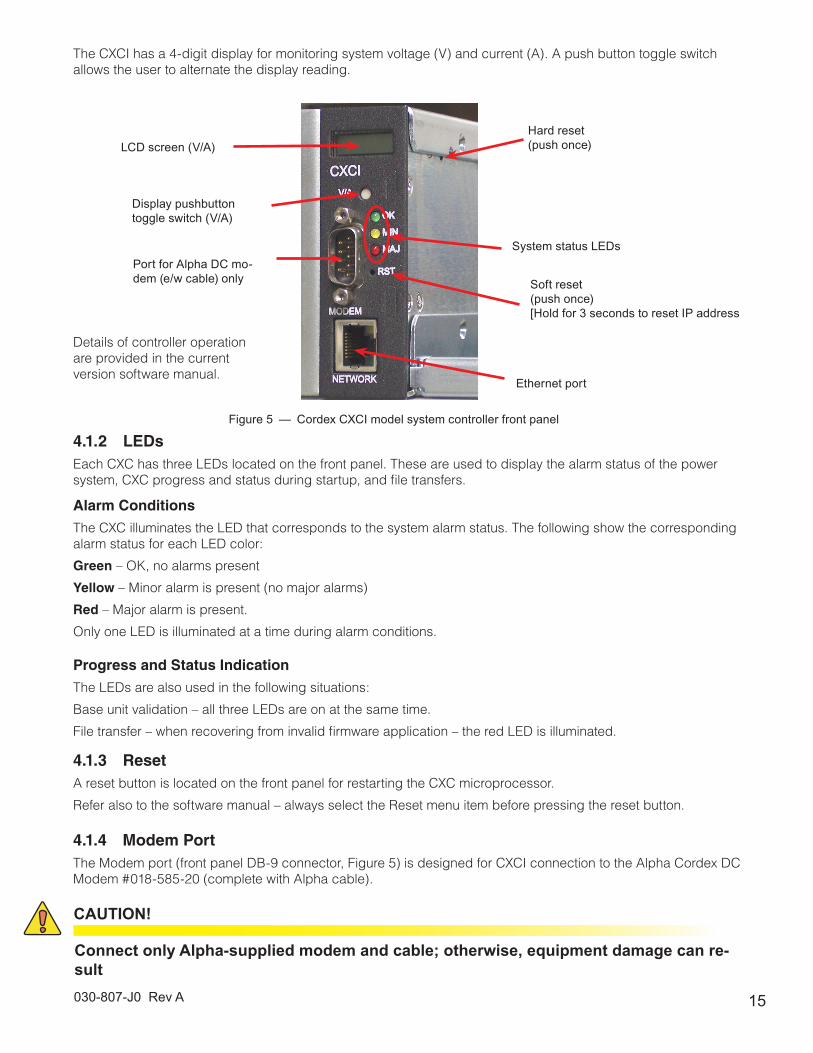
The CXCI has a 4-digit display for monitoring system voltage (V) and current (A). A push button toggle switch allows the user to alternate the display reading.
4.1.2 LEDsEach CXC has three LEDs located on the front panel. These are used to display the alarm status of the power system, CXC progress and status during startup, and file transfers.
Alarm Conditions
The CXC illuminates the LED that corresponds to the system alarm status. The following show the corresponding alarm status for each LED color:
Green – OK, no alarms present
Yellow – Minor alarm is present (no major alarms)
Red – Major alarm is present.
Only one LED is illuminated at a time during alarm conditions.
Progress and Status Indication
The LEDs are also used in the following situations:
Base unit validation – all three LEDs are on at the same time.
File transfer – when recovering from invalid firmware application – the red LED is illuminated.
4.1.3 ResetA reset button is located on the front panel for restarting the CXC microprocessor.
Refer also to the software manual – always select the Reset menu item before pressing the reset button.
4.1.4 Modem PortThe Modem port (front panel DB-9 connector, Figure 5) is designed for CXCI connection to the Alpha Cordex DC Modem #018-585-20 (complete with Alpha cable).
LCD screen (V/A)
Display pushbutton toggle switch (V/A)
Port for Alpha DC mo-dem (e/w cable) only
Details of controller operation are provided in the current version software manual.
Hard reset(push once)
Figure 5 — Cordex CXCI model system controller front panel
Ethernet port
System status LEDs
Soft reset(push once)[Hold for 3 seconds to reset IP address
CAUTION!
Connect only Alpha-supplied modem and cable; otherwise, equipment damage can re-sult

030-807-J0 Rev A16
4.1.5 Ethernet PortThe Ethernet port is designed for CXC connection to a user supplied network (TCP/IP secured by user) via a front panel RJ-45 jack and a standard network cable.
Local access (e.g. laptop computer) is also possible from the Ethernet port connection using a standard network crossover cable.
4.2 Analog Input ChannelsThe CXC has analog input channels for voltage, current, and temperature.
4.2.1 Voltage InputsTwo voltage input channels, V1 and V2, provide monitoring of discharge and charge voltage. The CXC software is pre-configured to monitor V2 for load voltage and for battery voltage. V2 is used as the system reference for rectifier float voltage, low voltage disconnect (LVD), system high voltage alarm, and system low voltage alarm. V1 is available for additional measurements.
4.2.2 Current InputsThe CXC software is pre-configured to monitor I1 for load current using an external 50mV current shunt.
4.2.3 Temperature InputsTwo temperature input channels, T1 and T2, provide monitoring of battery temperature and temperature compen-sation (temp comp) or room/ambient temperature. A voltage is supplied to these terminals to power the tempera-ture sensors.
4.3 Digital Input ChannelsThe CXC has digital input channels to monitor alarm/control signals from rectifiers, converters and many other types of equipment.
4.4 Alarm and Control Output RelaysThe CXC contains Form C digital alarm output relays to extend alarms and control external apparatus. Each internally generated alarm or control signal may be mapped to any one of the relays, or, several signals may be mapped to just one relay or none at all.
4.5 Network Connection and Remote CommunicationsThe Cordex system can be set up, monitored and tested via Ethernet 10/100 Base-T serial data connection. The communication protocol supports a web interface. All alarming and control of Cordex rectifiers is accomplished with a CXC via a CAN bus.
A step-by-step connection wizard (Windows® 2000 operating system) – provided to establish remote communi-cations with your CXC – is available via the Alpha website (www.alpha.ca./downloads/).
For the CXCM2 option, a secondary power input is required for use in a system with automatic low voltage battery disconnect (LVBD). V1 must be terminated on the battery side of the LVBD to measure battery voltage. This is critical to CXCM2 operation as it ensures a source of power should the disconnect device open the circuit to the main supply. This will maintain functional control of the LVBD.
NOTE:
17030-807-J0 Rev A
5. Inspection
5.1 Packing MaterialsAll Alpha products are shipped in rugged, double walled boxes and suspended via solid inserts to minimize shock that may occur during transportation. Packaging assemblies and methods are tested to International Safe Transit Association standards. Power systems are custom packaged in heavy-duty plywood crates.
Products are also packaged with Cortex. This plastic wrap contains a corrosive-inhibitor that protects the product from corrosion for up to two years.
Rectifiers and batteries are shipped on individual pallets and are packaged according to the manufacturer’s guidelines.
5.1.1 Returns for ServiceSave the original shipping container. If the product needs to be returned for service, it should be packaged in its original shipping container. If the original container is unavailable, make sure that the product is packed with at least three inches of shock-absorbing material to prevent shipping damage.
Alpha Technologies is not responsible for damage caused by improper packaging of returned products.
5.2 Check for DamageBefore unpacking the product, note any damage to the shipping container. Unpack the product and inspect the exterior for damage. If any damage is observed, contact the carrier immediately.
Continue the inspection for any internal damage. In the unlikely event of internal damage, inform the carrier and contact Alpha Technologies for advice on the impact of any damage.
5.3 General Receipt of ShipmentThe inventory included with your shipment depends on the options you have ordered. The options are clearly marked on the shipping container labels and bill of materials.
5.3.1 RacksConsult the packing slip and power system bill of materials to verify that you have the correct number of racks per your order.
5.3.2 Rectifiers (Purchased Separately)Consult the packing slip to verify that you have received the correct number of rectifiers per your order.
5.3.3 Miscellaneous Small PartsReview the packing slip and bill of materials to determine the part number of the “configuration kits” included with your system; e.g., 053-391-20-020 for CXPS 24-4T system with seven (7) foot Z4 relay rack.
Review the bill of materials to verify that all small parts are included.
5.3.4 Batteries (Purchased Separately)Verify that you have the correct number of batteries if applicable. Refer to the packing list.
Verify that you have all the necessary parts per your order.
Call Alpha Technologies if you have any questions before you proceed: 1 888 462-7487
030-807-J0 Rev A18
6. Installation
Only qualified personnel should install and connect the power components within the Alpha power system. For the battery installation, refer primarily to the manufacturer’s manual.
6.1 Safety Precautions
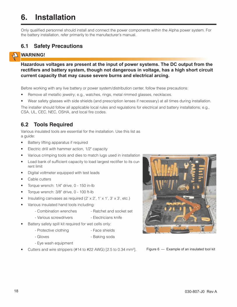
Figure 6 — Example of an insulated tool kit
6.2 Tools RequiredVarious insulated tools are essential for the installation. Use this list as a guide:
• Battery lifting apparatus if required
• Electric drill with hammer action, 1/2" capacity
• Various crimping tools and dies to match lugs used in installation
• Load bank of sufficient capacity to load largest rectifier to its cur-rent limit
• Digital voltmeter equipped with test leads
• Cable cutters
• Torque wrench: 1/4" drive, 0 - 150 in-lb
• Torque wrench: 3/8" drive, 0 - 100 ft-lb
• Insulating canvases as required (2' x 2', 1' x 1', 3' x 3', etc.)
• Various insulated hand tools including:
- Combination wrenches - Ratchet and socket set
- Various screwdrivers - Electricians knife
• Battery safety spill kit required for wet cells only:
- Protective clothing - Face shields
- Gloves - Baking soda
- Eye wash equipment
• Cutters and wire strippers (#14 to #22 AWG) [2.5 to 0.34 mm²].
WARNING!
Hazardous voltages are present at the input of power systems. The DC output from the rectifiers and battery system, though not dangerous in voltage, has a high short circuit current capacity that may cause severe burns and electrical arcing.
Before working with any live battery or power system/distribution center, follow these precautions:
• Remove all metallic jewelry; e.g., watches, rings, metal rimmed glasses, necklaces.
• Wear safety glasses with side shields (and prescription lenses if necessary) at all times during installation.
The installer should follow all applicable local rules and regulations for electrical and battery installations; e.g., CSA, UL, CEC, NEC, OSHA, and local fire codes.

19030-807-J0 Rev A
6.3 Power System Assembly and MountingThe power system must be mounted in a clean and dry environment. Sufficient free space must be provided at the front and rear of the power system. This is to meet the cooling requirements of the rectifiers and to allow easy access to the power system components.
The power system is suitable for installation in Network Telecommunication Facilities, locations where the NEC applies, and OSP applications.
NOTE:
6.3.1 Rack Mounted SystemsAttach the power system to the customer-provided relay rack using thread-forming mounting screws and star washers to ensure a proper electrical bond between the system chassis and the relay rack.
6.3.2 Floor Mounted Systems
1. Secure the system to a concrete floor using either heavy duty anchors (½" x 2½"), or for wooden floors, heavy-duty lag screws (5/8" x 2½"). Use appropriately sized flat washers.
2. If required, use isolating kits to isolate system from the floor.
3. Secure the relay rack to the overhead cable tray. Alpha does not supply the mechanical details necessary for overhead support.
6.3.3 Half-Rack/Battery Mounted Systems
1. Obtain the appropriate battery-to-power-system adapter plate. Secure the plate to the battery stack using heavy duty fasteners.
2. Secure the power system to the adapter plate using heavy duty fasteners.
3. Secure the power system to the overhead cable tray. Alpha does not supply the mechanical details necessary for overhead support.
6.4 Shelf Preparation/MountingMount the shelf in a clean and dry environment. Allow at least 1.75” of free space in front of the unit for unrestrict-ed cooling airflow.
For 030-807-20 (pre-RoHS 030-747-20), the shelf has been designed for flush mounting in a 23" relay rack.
For 030-809-20 (pre-RoHS 030-749-20), the shelf has been designed for flush mounting in a 19" relay rack.
Each shelf has an option for 6” offset mounting. See outline drawings at the rear of this manual.
Mounting brackets accommodate either 1" or 1-3/4" rack spacing. Mount the shelf to the rack using at least two #12 – 24 x 1/2” screws in each bracket. Philips-type screws and screwdriver should be used to eliminate the pos-sibility of slippage and scratching of the unit’s exterior. Use washers (such as internal tooth) or special screws that are designed to cut through the painted surface to ensure a good chassis ground.
6.5 Rectifier Module Insertion/Removal
Do not force a module into position if it does not seat properly. All modules are keyed to ensure that the correct module type is used.
NOTE:
It is recommended to insert the first module into the front leftmost position using the side of the shelf (or the optional shelf-mounted controller) as a guide. Subsequent mod-ules may be inserted using the previous module as a guide.
NOTE:
030-807-J0 Rev A20
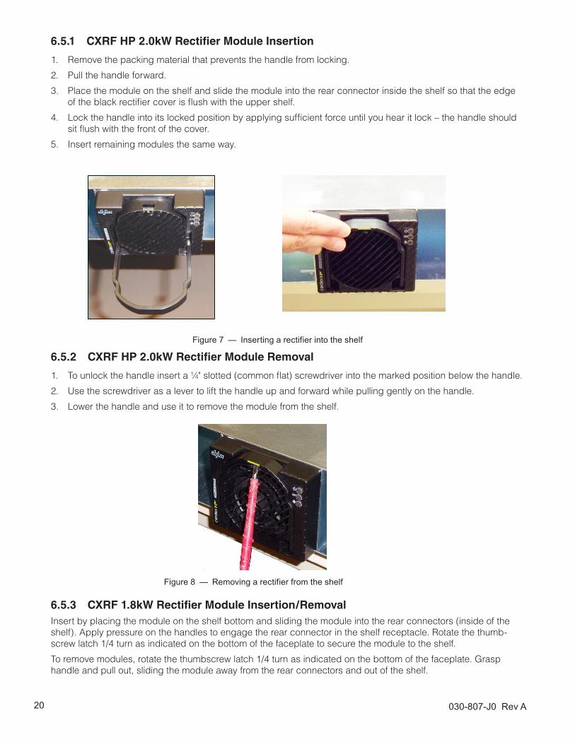
6.5.1 CXRF HP 2.0kW Rectifier Module Insertion
1. Remove the packing material that prevents the handle from locking.
2. Pull the handle forward.
3. Place the module on the shelf and slide the module into the rear connector inside the shelf so that the edge of the black rectifier cover is flush with the upper shelf.
4. Lock the handle into its locked position by applying sufficient force until you hear it lock – the handle should sit flush with the front of the cover.
5. Insert remaining modules the same way.
6.5.3 CXRF 1.8kW Rectifier Module Insertion/RemovalInsert by placing the module on the shelf bottom and sliding the module into the rear connectors (inside of the shelf). Apply pressure on the handles to engage the rear connector in the shelf receptacle. Rotate the thumb-screw latch 1/4 turn as indicated on the bottom of the faceplate to secure the module to the shelf.
To remove modules, rotate the thumbscrew latch 1/4 turn as indicated on the bottom of the faceplate. Grasp handle and pull out, sliding the module away from the rear connectors and out of the shelf.
6.5.2 CXRF HP 2.0kW Rectifier Module Removal
1. To unlock the handle insert a ¼" slotted (common flat) screwdriver into the marked position below the handle.
2. Use the screwdriver as a lever to lift the handle up and forward while pulling gently on the handle.
3. Lower the handle and use it to remove the module from the shelf.
Figure 7 — Inserting a rectifier into the shelf
Figure 8 — Removing a rectifier from the shelf

21030-807-J0 Rev A
6.6.1 Preparation/MountingThe batteries should be located in a temperature-controlled environment. The temperature should be regulated to approximately 25°C (77°F). Significantly lower temperatures reduce the performance and higher temperatures decrease the life expectancy.
Provide adequate ventilation. VRLA batteries, though not requiring special ventilation requirements of a flooded battery, should not be installed in an airtight enclosure. Hydrogen gas can be emitted from a failed battery.
If applicable, clean the cells before assembly as per the battery manufacturer's recommendations. First neutralize any acid with a baking soda and water solution, then wipe the cells with clean water.
6.6.2 Installation of Batteries
6.6 Battery InstallationThis information is provided as a guideline and is not meant to imply that batteries are part of this power system.
WARNING!
Follow the battery manufacturer’s safety recommendations when working around bat-tery systems and review the safety instructions provided in this manual.
WARNING!
Verify that all battery breakers, DC circuit breakers, and fuses on the distribution panels are either in the OFF position or removed.
Apply a corrosion-inhibiting agent, such as NO-OX-ID “A”, on all battery terminal connections.
1. If required, assemble the battery rack and the cells or mono-blocks as per the installation instructions supplied with the batteries.
2. Ensure that the battery output cabling can reach the [+] and [–] terminals of the series battery string and that the batteries are oriented correctly for easy installation of the inter-unit “series” connectors.
3. Remove any NO-OX-ID “A” grease from battery terminals.
4. Burnish the terminal posts with a non-metallic brush, polishing pad or 3M Scotch Brite scouring pad.
5. Apply a light coating of NO-OX-ID “A” grease to the terminal posts.
6. If lead plated inter-unit connectors are used, they should also be burnished and NO-OX-ID “A” grease applied as above. Install the inter-unit connectors.
7. After all battery connections are completed, torque the connections as per the battery specifications (typically 100 in-lbs).
Refer to the system startup procedure before connecting the batteries online.
030-807-J0 Rev A22
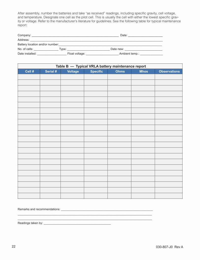
After assembly, number the batteries and take “as received” readings, including specific gravity, cell voltage, and temperature. Designate one cell as the pilot cell. This is usually the cell with either the lowest specific grav-ity or voltage. Refer to the manufacturer's literature for guidelines. See the following table for typical maintenance report:
Company: _____________________________________________________ Date: _____________________Address: _________________________________________________________________________________Battery location and/or number:_______________________________________________________________No. of cells: _______________ Type: __________________________ Date new: _______________________Date installed: __________________ Float voltage: ____________________ Ambient temp.: ______________
Table B — Typical VRLA battery maintenance reportCell # Serial # Voltage Specific Ohms Mhos Observations
Remarks and recommendations: ____________________________________________________________________________________________________________________________________________________________________________________________________________________________Readings taken by: _________________________________________

23030-807-J0 Rev A
7. Wiring
This chapter provides cabling details and notes on cable sizing for DC applications with respect to the product.
Ensure that the power is switched off by switching off all rectifiers and removing bat-tery line fuses or connections before attempting work on the wiring. Use a voltmeter to verify the absence of a voltage. Clearly mark the correct polarity of the battery leads before starting work on DC connections.
Refer to the Installation section for additional safety precautions and tools required.
7.1 Power System Chassis Ground and DC Ground ReferenceThis power system is suitable for installation as part of a Common Bonding Network (CBN) and is intended to be used in a DC-C configuration (common DC return). In this configuration, the common return bus should be con-nected to the building master ground bus (MGB), or floor ground bus (FGB) in a larger building. This connection provides a system reference and a low impedance path to the ground for surges, transients, noise, etc.
7.2 AC Feeder Protection/SizingFor 030-807-20 (pre-RoHS 030-747-20), a dual feed divides the rectifiers into two (2) groups to be supplied by separate feeds. See the customer connections drawing 030-807-08 (modules are numbered left to right).
For 030-809-20 (pre-RoHS 030-749-20), separate terminations are provided for each rectifier module input. Refer to the customer connections drawing 030-809-08 for dual feed and other rectifier feed options.
To maximize system reliability, each power module should be fed from a dedicated protection feeder breaker located at the AC distribution panel. The feeder breaker can also act as the disconnect device for the connected module. Refer to the shelf specifications, 030-807-B1 and 030-809-B1, (at the end of this manual) for Alpha breaker/wire size recommendations.
7.3 AC Input Connections
WARNING!
To minimize EMI disturbances, the AC input wires must be routed in flexible or rigid conduit and located as far away as possible from the DC power wires.
Ensure that all modules are removed from the shelf. Refer to the customer connections drawings at the rear of the manual for AC terminal block location.
WARNING!
Use care when removing or replacing the covers for the AC input connections. Never assume that an electrical connection or conductor is not energized.
If the shelf is factory-equipped with a line cord, proceed to the next section.
For the mini-fit connectors option, terminate cable leads with appropriate pin and socket connectors.
For the terminal blocks option, each terminal pair (L1 and L2) relates to a feed or individual module as marked.
Secure the wires to the AC input and chassis ground terminals as required. Use cable ties with the mount
provided for wire management.
CAUTION!

030-807-J0 Rev A24
The DC output wires must be UL approved XHHW or RHH/RHW (RW90 type for Canadian users). Control and sense wires must be UL approved Style 1015 (TEW type for Canadian users).
The common output leg of the rectifier system must be connected to the ground. This is typically done at the load common termination point.
7.4.1 Battery ConnectionsBattery cables must be sized for a 0.25 V drop from the battery to the power system at full load including antici-pated growth. The cables must also meet ampacity requirements. Cables terminating directly on the battery posts or connection details must be secured so that there is no stress on the battery posts. Lead plated lugs and lead plated or stainless steel hardware must be used on all terminations at vented batteries to reduce corrosion.
Prepare, route, and connect cables from the power system to the battery termination details. Burnish the terminat-ing points and apply a corrosion-inhibiting agent, such as NO-OX-ID “A”, to all battery terminal connections.
Do not complete the final live connections to the battery. Leave open and insulate the final connections or remove the battery fuses. Switch off the battery contacts if used. Refer to the system startup procedure before connect-ing the batteries online.
7.4 DC Output Connections
WARNING!
Leave cables or bus bars disconnected at the battery and verify the output polarity us-ing a voltmeter. Make battery connections only after all other wiring is completed.

25030-807-J0 Rev A
7.5 CAN Serial PortsTwo CAN Serial ports (modular jacks with offset latches) are provided for communications with Alpha Cordex rectifiers and other CAN-enabled equipment. These are located on the right side of the rectifier shelf as viewed from the front (see Figure 9).
Daisy-chain from shelf to shelf (CAN OUT of one shelf to CAN IN of another) and ensure that only the last shelf is terminated.
7.5.1 CAN TerminationA jumper, or switch depending on your configuration, allows setting the CAN OUT to be open to the next shelf in the system or terminated. Termination must be enabled in final shelf on the CAN bus only. Access the termination selection inside the shelf by removing the right most rectifier #4 or #5. Refer to the shelf drawings at the end of this manual.
Figure 9 — CAN termination selection and serial ports
CAN serial ports – right view
CAN termination selection – front view
CAN termination jumper
030-807-J0 Rev A26
7.5.2 Analog Inputs
Ensure that the correct polarity is used for all input cable terminations.
The analog input channels are used to monitor various types of electrical signals. Some of the analog channels are reserved for specific signals, while others are designated as general-purpose inputs, which accommodate various types of analog signals. The input cables should be bundled together and routed through the entry holes.
Default configurations and terminal numbers described below have been summarized in the drawings located at the rear of this manual.
To reduce risk of fire, use only 0.129 mm² (#26 AWG) or larger wire.
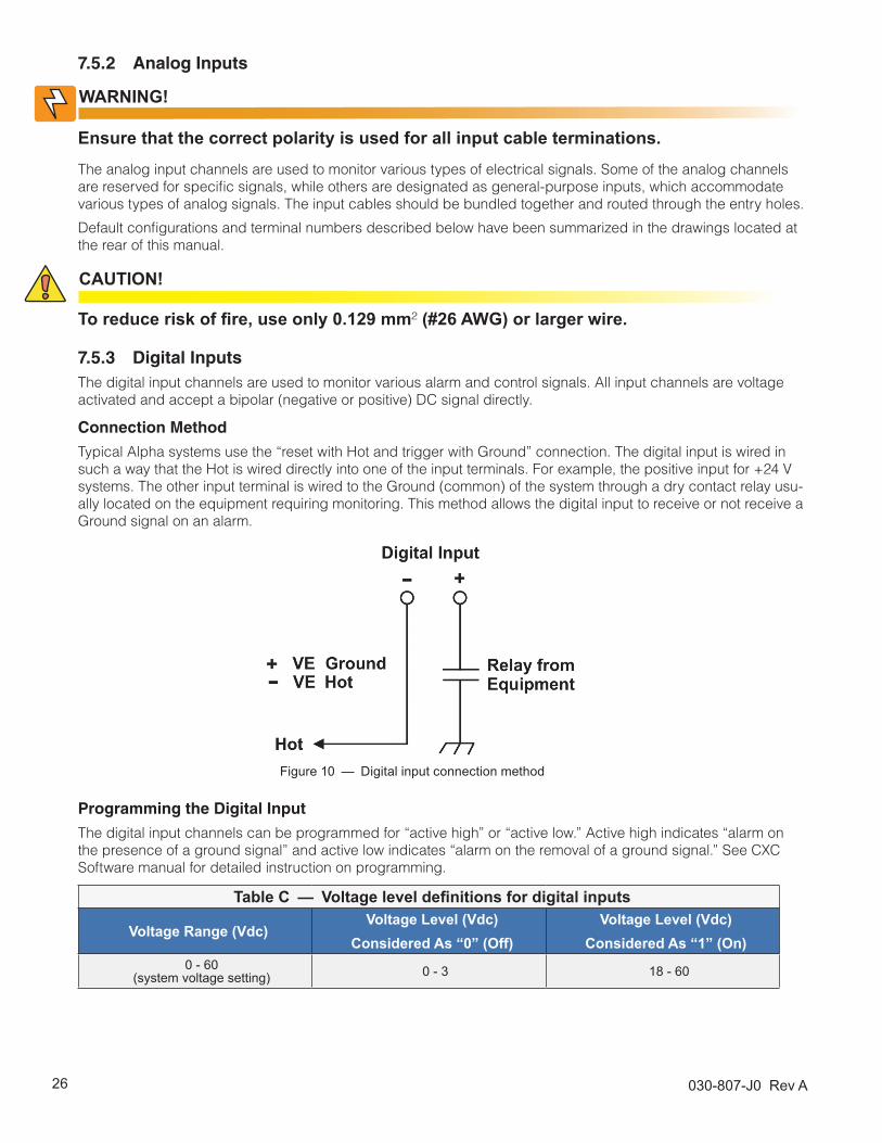
7.5.3 Digital InputsThe digital input channels are used to monitor various alarm and control signals. All input channels are voltage activated and accept a bipolar (negative or positive) DC signal directly.
Connection Method
Typical Alpha systems use the “reset with Hot and trigger with Ground” connection. The digital input is wired in such a way that the Hot is wired directly into one of the input terminals. For example, the positive input for +24 V systems. The other input terminal is wired to the Ground (common) of the system through a dry contact relay usu-ally located on the equipment requiring monitoring. This method allows the digital input to receive or not receive a Ground signal on an alarm.
WARNING!
CAUTION!
Figure 10 — Digital input connection method
Programming the Digital Input
The digital input channels can be programmed for “active high” or “active low.” Active high indicates “alarm on the presence of a ground signal” and active low indicates “alarm on the removal of a ground signal.” See CXC Software manual for detailed instruction on programming.
Table C — Voltage level definitions for digital inputs
Voltage Range (Vdc)Voltage Level (Vdc)
Considered As “0” (Off)Voltage Level (Vdc)
Considered As “1” (On)0 - 60
(system voltage setting) 0 - 3 18 - 60

27030-807-J0 Rev A
7.5.4 Relay OutputsTerminals provide contacts for extending various alarm or control signals. Each relay output can be wired for NO or NC operation during an alarm or control condition (Figure 12).
Figure 11 — Relay connections in the de-energized state
Relays can be programmed to energize or de-energize during an alarm condition (see CXC Software manual). When the CXC reset button is pressed or power is lost, all relays de-energize.
LVD Control
The LVD Control functions can be hard wired directly from the assigned relay output to the LVD contactor panel. See Controls Menu Defaults in the CXC Software manual.
7.6 Network Connection and Remote Communications via CXCThe Cordex system can be set up, monitored and tested over an Ethernet 10/100 Base-T serial data connection. The communication protocol supports a web interface.
Some standard scenarios are described below:
7.6.1 Ethernet Port for Network Connection (Standard Network Cable)The Ethernet port is designed for CXC connection to a user supplied network (TCP/IP secured by user) via a front panel RJ-45 jack. Connect to the Cordex shelf using a standard network cable.
7.6.2 Ethernet Port for Local Connection (Crossover Cable)Local access (e.g. with a laptop computer) is available from the Ethernet port connection using a standard net-work crossover cable.

030-807-J0 Rev A28
8. System Startup
Visually inspect the installation thoroughly.
After completing the system installation and power system wiring, perform the following startup and test proce-dure to ensure proper operation:
8.1 Check System Connections1. Make sure that the AC input power is switched off, the batteries are disconnected, and all the power modules
are removed from the shelf.
2. Triple-check the polarity of all connections.
8.2 Verify AC and Power the Rectifier Shelf1. Install one power module.
2. Verify that the AC input voltage is correct and switch on the corresponding feeder breaker. The power module OK LED will illuminate after a preset start delay.
3. Using the CXC, test the functionality of various module alarms and controls.
8.3 Check Battery Polarity and Connect1. Use a voltmeter to verify that the battery polarity is correct. Ensure that no cells or batteries are reversed.
2. Connect the batteries to the output of the system.
3. Install the remaining power modules.
4. In the adjustments menu of the CXC, set the float and equalize voltages to the levels specified by the battery manufacturer.
5. Using the CXC, test the functionality of the various module alarms and controls. Perform a load test with the system using a resistive load box.
6. Enable the temperature compensation (temp comp) feature in the batteries menu. Program the settings for slope and breakpoints (upper and lower) according to the specific batteries used.
8.3.1 CXC Alarm Configuration for Nominal 120Vac OperationThe default setting for low AC voltage alarming is 180Vac. For nominal 120Vac operation, it is recommended to reset this value to 100Vac.
To reconfigure this alarm parameter, go to “Alarms” – “Configure Alarms”. Under “Alarm Configuration,” select “Voltage Alarms.” Select and modify the activation value for “AC Mains Low” to 100Vac. Submit changes to save the new configuration.
8.4 CXC Reset8.4.1 Soft ResetThe reset button, located on the front panel of the optional CXC (e.g. CXCM2 or CXCI), is for restarting the micro-processor. When pressed momentarily, the unit beeps twice then resets. The front-panel LED’s will illuminate temporarily, but will extinguish after the system has finished its 15 second self-test.
8.4.2 CXCI IP Address ResetTo reset the IP address, press and hold the front panel reset button for three seconds. The CXCI unit will beep three times, IP will be reset (to 10.10.10.201) and DHCP will be disabled. The settings will be saved and the unit will then reset.
This will allow local access; e.g., with a laptop and a standard network crossover cable. See current version soft-ware manual for details.

29030-807-J0 Rev A
8.4.3 CXCI Hard ResetThere is a second reset button located to the right of the front panel on the side of the CXCI. This may be used to restart the microprocessor in the event that the front panel (soft) reset button fails to operate as described above.
CAUTION!
Use of hard reset may cause loss of data.
To access the hard reset button, remove the rectifier module adjacent to the CXCI.
8.4.4 Time SettingsThe CXCI, upon startup*, will set the time based on the following:
• Attempt to synchronize with the NTP server (see www.NTP.org).
• Retrieve the last time stamp from the Event Log.
• Retrieve the last time stamp from the Statistics Log.
• Set the time to 2005-01-01 midnight.
*Whenever the unit is reset or power is completely removed from the CXCI.
030-807-J0 Rev A30
9. Operation
9.1 Main Rectifier StatesThe rectifier operation can be broken up into five main states:
1. Off
2. Start Delay
3. Soft Start
4. Normal Operation
5. Switching Off
Each state is distinct and necessary for the operation of the rectifier. These states are briefly described below.
9.1.1 Off StateThe rectifier is in the Off state immediately after power is applied to the rectifier or after a rectifier shutdown. The shutdown source may be a remote or local shutdown, an AC shutdown, an Over voltage protection (OVP) shut-down, or a thermal shutdown.
When the rectifier is in the Off state, the DC-DC converter is switched off and the CXC is monitoring its inputs for the proper conditions to begin the start up sequence.
When the conditions have been met for the rectifier to start up, it will transition to the Start Delay state.
9.1.2 Start Delay StateWhen the rectifier is in the Start Delay state, the DC-DC converter is held off and not sourcing power. The rectifier is waiting for a set time before transitioning to the next state.
When the rectifier is in the Start Delay state, the CXC continues to monitor its inputs.
After the Start Delay state, the rectifier transitions to the Soft Start state.
9.1.3 Soft Start StateWhen the rectifier is in the Soft Start state, it is switched on and the output voltage and output current are gradu-ally increased. If a load is present, the rectifier begins to source power to reduce the instantaneous load on the AC source.
When the voltage and current limit ramp ups have finished, the rectifier transitions to the Normal Operation state.
9.1.4 Normal Operation StateDuring the Normal Operation state, the rectifier performs all of the rectifier functions and features.
From the Normal Operation state, the only valid transition is to the Switching Off state. This transition happens when the rectifier is required to shut down.
9.1.5 Switching Off StateThe Switching Off state is entered to provide a short delay before the rectifier actually switches off. This is done to take care of any initialization requirements.
When this short delay has elapsed, the rectifier transitions to the Off state.
31030-807-J0 Rev A
9.2 Main Rectifier ModesIn addition to the main rectifier states, there is a set of main rectifier modes. These modes can be divided into two categories: the output voltage mode and the output current/power mode.
9.2.1 Output Voltage ModesVoltage modes can be thought of as modes that, under software control, directly adjust the output voltage. The qualification, “under software control”, is made because there are processes that occur in the rectifier that can change the output voltage and not adjust the output voltage directly (if the rectifier has reached the current limit for example).
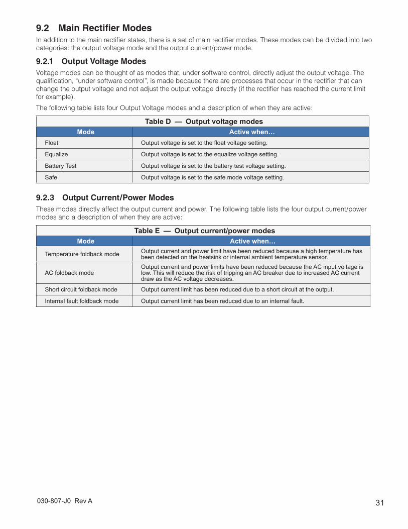
The following table lists four Output Voltage modes and a description of when they are active:
Table D — Output voltage modesMode Active when…
Float Output voltage is set to the float voltage setting.
Equalize Output voltage is set to the equalize voltage setting.
Battery Test Output voltage is set to the battery test voltage setting.
Safe Output voltage is set to the safe mode voltage setting.
9.2.3 Output Current/Power ModesThese modes directly affect the output current and power. The following table lists the four output current/power modes and a description of when they are active:
Table E — Output current/power modesMode Active when…
Temperature foldback mode Output current and power limit have been reduced because a high temperature has been detected on the heatsink or internal ambient temperature sensor.
AC foldback modeOutput current and power limits have been reduced because the AC input voltage is low. This will reduce the risk of tripping an AC breaker due to increased AC current draw as the AC voltage decreases.
Short circuit foldback mode Output current limit has been reduced due to a short circuit at the output.
Internal fault foldback mode Output current limit has been reduced due to an internal fault.

030-807-J0 Rev A32
9.3 Factory Ranges and Defaults
9.3.1 Cordex HP 48V-1.8kW/2.0kWThe following table shows the rectifier settings/ranges/defaults. Changes are made via the CXC
Table F — Cordex HP 48V-1.8kW factory ranges and defaultsSetting Range (minimum to maximum) Default
Float (FL) Voltage 47.5 – 58.2V 54V
Equalize (EQ) Voltage 49.8 – 60.2V 55V
Battery Test (BT) Voltage 44 – 52V 46V
OVP See note below – 63V 57V
Current Limit (CL) 20 – 100% 100%
Power Limit (PL) 0 – 100% 100%
Module Start Delay 0 – 250s 1s
System Start Delay 0 – 600s 0s
Low Voltage Alarm (LVA) 42 – 52V 44V
High Voltage Alarm (HVA) 52 – 63V 55.5V
EQ Timeout 1 – 2399h 30h
BT Timeout 1 – 250h 8h
Softstart Ramp-rate Normal/Fast Normal
CL/PL Alarm Enable/Disable Enable
Remote Shutdown Enable/Disable Enable
Ramp Test Enable/Disable Enable
The OVP cannot be set below the present system/FL/EQ/BT voltage setting or the safe mode voltage of 51.4 V.
33030-807-J0 Rev A
Table G — Sample maintenance logProcedure Date CompletedClean ventilation openings.
Inspect all system connections. Re-torque if necessary.
Verify alarm/control settings.
Verify alarm relay operation.
10.1 Fan Replacement
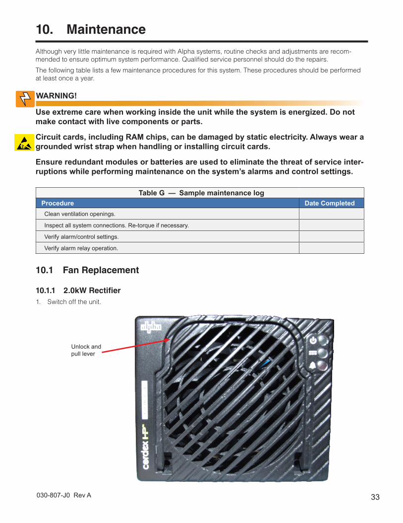
10.1.1 2.0kW Rectifier1. Switch off the unit.
Unlock and pull lever
10. Maintenance
Although very little maintenance is required with Alpha systems, routine checks and adjustments are recom-mended to ensure optimum system performance. Qualified service personnel should do the repairs.
The following table lists a few maintenance procedures for this system. These procedures should be performed at least once a year.
Use extreme care when working inside the unit while the system is energized. Do not make contact with live components or parts.
Circuit cards, including RAM chips, can be damaged by static electricity. Always wear a grounded wrist strap when handling or installing circuit cards.
Ensure redundant modules or batteries are used to eliminate the threat of service inter-ruptions while performing maintenance on the system’s alarms and control settings.
WARNING!
030-807-J0 Rev A34
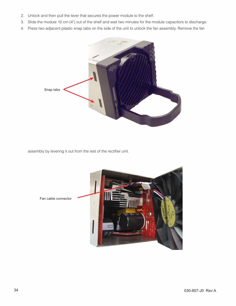
2. Unlock and then pull the lever that secures the power module to the shelf.
3. Slide the module 10 cm (4") out of the shelf and wait two minutes for the module capacitors to discharge.
4. Press two adjacent plastic snap tabs on the side of the unit to unlock the fan assembly. Remove the fan
assembly by levering it out from the rest of the rectifier unit.
Snap tabs
Fan cable connector

35030-807-J0 Rev A
5. Disconnect the fan cables from the module by pulling out the fan cable connector.
6. Press the snap hooks that secure the fan to the fan assembly, and separate the fan from the assembly.
7. Install the replacement fans following the preceding steps in reverse order.
Snap hooks
Fan
Fan assembly
Fan
Fan cables
the customer connections drawing

030-807-J0 Rev A36
10.2 CXRF 1.8kW Rectifier Fan Replacement1. Shut off the unit and unlatch (rotate) the front fastener that secures the power module to the shelf.
2. Slide the module 10 cm (4”) out of the shelf and wait two minutes for module capacitors to discharge.
3. Remove the screws (each side) that secure the front panel to the module chassis.
4. Slide the front panel out.
5. Disconnect the fan power lead wires and front panel ribbon cable from the module.
6. Remove the screws that secure the fan to the front panel.
7. Note the direction of airflow and remove the fan from the front panel.
8. Install the replacement fan following the preceding steps in reverse order.
10.3 MOV ReplacementThe MOVs (metal oxide varistor) are used to protect the power modules from power line surges and surges caused by lightning strikes.
10.3.1 CXRF HP 2.0kW RectifierIf a MOV is damaged by high capacity surges,it cannot be replaced in the field. Return the rectifier to Alpha for service when a MOV is damaged.
10.3.2 CXRF 1.8kW RectifierHigh capacity surges may permanently damage MOVs, but they are easily replaced in the field using the follow-ing procedure:
1. Shut off the unit and unlatch (rotate 1/4-turn) the front fastener that secures the power module to the shelf.
2. Slide the module 10 cm (4”) out of the shelf and wait two minutes for module capacitors to discharge.
3. Turn the module around to face the back of the unit and remove the screw (module bottom toward the rear) securing the MOV cover.
4. Remove the cover and locate the MOV printed circuit board (PCB).
5. Remove the screws that secure the MOV PCB.
6. Decontaminate the area and unit with flux remover or a similar cleaning compound. This is to remove any metallic particles or carbon, which may have been deposited when the MOV failed.
7. Install the replacement MOV PCB following the preceding steps in reverse order.
10.4 CXCI or CXCM2 Replacement Procedure1. Write down the CXC communication information: dynamic or static IP, IP address, and gateway.
2. Connect user laptop to CXC per software manual; standard network crossover cable to Ethernet port.
3. A step-by-step connection (wizard) application (Windows® 2000 operating system) – provided to establish remote communications with your CXC – is available via the Alpha website www.alpha.ca/downloads/. The CXC Connection Wizard will save your LAN configuration and restore it back when exiting the application.
4. Save CXC configuration file (see software manual).
5. Bypass system LVD as required and remove signal wires (via DB connectors) from the CXC.
CAUTION!
If the LVD is not bypassed, the DC loads will be shut down when the wiring to the con-troller is removed.
6. Ensure rectifier is in the right-most position.

37030-807-J0 Rev A
10.4.1 CXCI Replacement7. Remove rectifier in the left-most position in order to access the side of the CXCI where the mounting screws
are located.
8. Remove four (4) mounting screws from the CXCI as shown in Figure 12 below. The first two screws will release the front panel from the controller circuit board to expose the third screw which releases the LCD. Carefully remove the LCD to expose the fourth and final screw to release the remains of the CXCI.
9. To install a CXCM2, place on the shelf bottom, slide into position, and turn latch (near the bottom of the
Screw 3 and 4
Screw 1 and 2 (2PL)
Figure 12 — CXCI replacement detail
faceplate) to secure to shelf; otherwise, replace CXCI following steps 7 and 8 in reverse order. CAUTION - Do not push on the LCD. Continue to step 13 to complete procedure.
10.4.2 CXCM2 Replacement10. To remove, loosen the screw on the bottom of the faceplate. Grasp handle and pull out of the shelf.
11. If replacing a CXCI with a CXCM2, remove rectifier in the left-most position in order to provide room and proceed to step 9.
12. Insert by placing the CXCM2 on the shelf bottom, slide into position, and turn latch (near the bottom of the faceplate) to secure to shelf. CAUTION - Do not push on the LCD. To install a CXCI, follow steps 7 and 8 in reverse order. Continue to step 13 to complete procedure.
13. Review steps 1 through 3 with respect to new installation and upload the saved CXC configuration file to the new controller.
14. Use a meter to verify the bus voltage and current shunt. Recalibrate as required due to differences in the new CXC.
15. Replace rectifiers and signal wires. Remove LVD bypass.

030-807-J0 Rev A38
11. Alpha Conventions
11.1 Numbering SystemThe last two digits of the part number indicate the type of drawing, for example:
• “-06” Outline Drawing
• “-08” Customer Connections
• “-20” Main Assembly
11.2 Acronyms and DefinitionsAC Alternating current
ANSI American National Standards InstituteAWG American Wire GaugeBTU British thermal unitCAN Controller area networkCEC Canadian Electrical CodeCSA Canadian Standards AssociationCX Cordex™ series; e.g., CXC for Cordex System ControllerDC Direct current
DHCP Dynamic Host Configuration ProtocolEIA Electronic Industries Alliance
EMC Electromagnetic compatibilityEMI Electromagnetic interferenceERM Electromagnetic Compatibility and Radio Spectrum MattersESD Electrostatic DischargeFCC Federal Communications Commission (for the USA)GSM Group Speciale Mobile (global system for mobile communications)HVSD High voltage shutdownIEC International Electrotechnical Commission
IEEE Institute of Electrical and Electronics EngineersIP Internet Protocol
LED Light emitting diodeLVD Low voltage disconnectMIL One thousandth of an inch; used in expressing wire cross sectional area
MOV Metal oxide varistorMTBF Mean time between failures
NC Normally closedNEC National Electrical Code (for the USA)NO Normally open
OSHA Occupational Safety & Health AdministrationOVP Over voltage protectionRAM Random access memoryRU Rack unit (1.75”)
TCP/IP Transmission Control Protocol / Internet ProtocolTHD Total harmonic distortionUL Underwriters Laboratories
VRLA Valve regulated lead acid

39030-807-J0 Rev A
12. Warranty and Service Information
Technical Support
Free Technical Support 24/7/365 is part of the Alpha customer satisfaction commitment. The phone numbers below can also be used to access a wide range of service solutions both at your premise and at the Alpha facility nearest you.
In Canada and the USA, call toll free 1-888-462-7487 24 hours a day, seven days a week. Customers outside Canada and the USA, call +1-604-436-5547.
Warranty
Alpha Technologies Ltd. warrants all equipment manufactured by it to be free from defects in parts and labor, for a period of two years from the date of shipment from the factory. The warranty provides for repairing, replacing or issuing credit (at Alpha’s discretion) for any equipment manufactured by it and returned by the customer to the factory or other authorized location during the warranty period. There are limitations to this warranty cover-age. The warranty does not provide to the customer or other parties any remedies other than the above. It does not provide coverage for any loss of profits, loss of use, costs for removal or installation of defective equipment, damages or consequential damages based upon equipment failure during or after the warranty period. No other obligations are expressed or implied. Warranty also does not cover damage or equipment failure due to cause(s) external to the unit including, but not limited to, environmental conditions, water damage, power surges or any other external influence.
The customer is responsible for all shipping and handling charges. Where products are covered under warranty Alpha will pay the cost of shipping the repaired or replacement unit back to the customer.
Battery Warranty
Note that battery warranty terms and conditions vary by battery and by intended use. The most common battery warranty provided by Alpha is a two year full replacement warranty with a pro-rated warranty for the following three years. Pro rated warranty provides a credit applicable toward the purchase of new batteries from Alpha. The credit is calculated as the purchase price multiplied by the percentage of the battery life that was not available (in months). Battery warranty coverage is lost where the battery charge is not maintained for 6 months. Contact your Alpha sales representative or the Technical Support team at the above number to understand your entitlements under Battery Warranty.
Extended Warranty
The terms of warranty can be extended in time by purchase of an Extended Warranty. Warranty extensions are available on a per year basis and can be purchased during the initial warranty period.
Return of Material
Please contact Technical Support at the number above to obtain a Service Repair Order (or Return Material Authorization) number BEFORE sending material back. This will ensure that your service needs are handled promptly and efficiently.
On Site Services and Service Plans
A wide range of services are available at your location including installation, commissioning, preventative main-tenance, remedial maintenance, battery replacement, battery delivery, etc. Preventative maintenance is recom-mended for Alpha products at least once per year. Customers can arrange to have these services provided automatically with one annual payment.
Service Centers
For a list of service centers, please visit:
http://www.alpha.ca/web2/about-alpha/service-centers.html
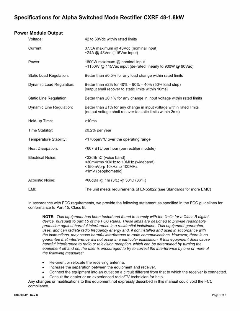
Specifications for Alpha Switched Mode Rectifier CXRF 48-1.8kW
010-602-B1 Rev C Page 1 of 3
Power Module Output Voltage: 42 to 60Vdc within rated limits Current: 37.5A maximum @ 48Vdc (nominal input)
~24A @ 48Vdc (115Vac input) Power: 1800W maximum @ nominal input
~1150W @ 115Vac input (de-rated linearly to 900W @ 90Vac) Static Load Regulation: Better than ±0.5% for any load change within rated limits Dynamic Load Regulation: Better than ±2% for 40% – 90% – 40% (50% load step)
[output shall recover to static limits within 10ms] Static Line Regulation: Better than ±0.1% for any change in input voltage within rated limits Dynamic Line Regulation: Better than ±1% for any change in input voltage within rated limits
(output voltage shall recover to static limits within 2ms) Hold-up Time: >10ms Time Stability: ≤0.2% per year Temperature Stability: <170ppm/°C over the operating range Heat Dissipation: <607 BTU per hour (per rectifier module) Electrical Noise: <32dBrnC (voice band)
<30mVrms 10kHz to 10MHz (wideband) <150mVp-p 10kHz to 100MHz <1mV (psophometric)
Acoustic Noise: <60dBa @ 1m (3ft.) @ 30°C (86°F) EMI: The unit meets requirements of EN55022 (see Standards for more EMC) In accordance with FCC requirements, we provide the following statement as specified in the FCC guidelines for conformance to Part 15, Class B:
NOTE: This equipment has been tested and found to comply with the limits for a Class B digital device, pursuant to part 15 of the FCC Rules. These limits are designed to provide reasonable protection against harmful interference in a residential installation. This equipment generates, uses, and can radiate radio frequency energy and, if not installed and used in accordance with the instructions, may cause harmful interference to radio communications. However, there is no guarantee that interference will not occur in a particular installation. If this equipment does cause harmful interference to radio or television reception, which can be determined by turning the equipment off and on, the user is encouraged to try to correct the interference by one or more of the following measures: • Re-orient or relocate the receiving antenna. • Increase the separation between the equipment and receiver. • Connect the equipment into an outlet on a circuit different from that to which the receiver is connected. • Consult the dealer or an experienced radio/TV technician for help.
Any changes or modifications to this equipment not expressly described in this manual could void the FCC compliance.
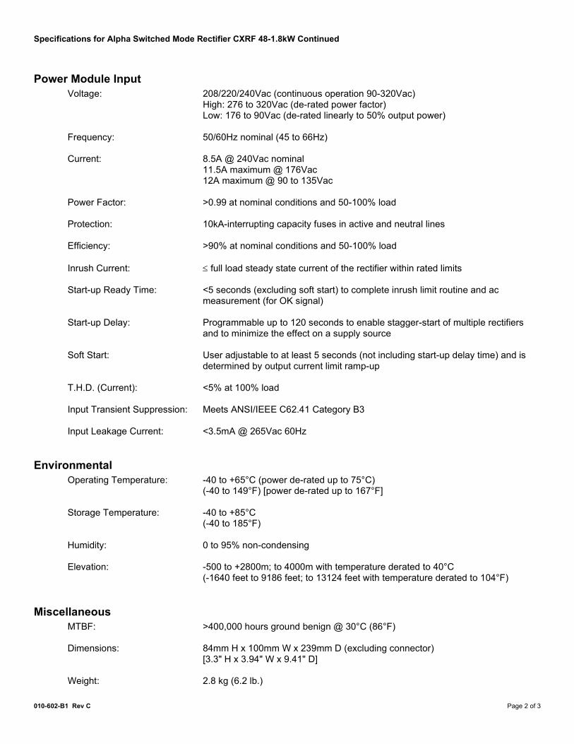
Specifications for Alpha Switched Mode Rectifier CXRF 48-1.8kW Continued
010-602-B1 Rev C Page 2 of 3
Power Module Input Voltage: 208/220/240Vac (continuous operation 90-320Vac)
High: 276 to 320Vac (de-rated power factor) Low: 176 to 90Vac (de-rated linearly to 50% output power)
Frequency: 50/60Hz nominal (45 to 66Hz) Current: 8.5A @ 240Vac nominal
11.5A maximum @ 176Vac 12A maximum @ 90 to 135Vac
Power Factor: >0.99 at nominal conditions and 50-100% load Protection: 10kA-interrupting capacity fuses in active and neutral lines Efficiency: >90% at nominal conditions and 50-100% load Inrush Current: ≤ full load steady state current of the rectifier within rated limits Start-up Ready Time: <5 seconds (excluding soft start) to complete inrush limit routine and ac
measurement (for OK signal) Start-up Delay: Programmable up to 120 seconds to enable stagger-start of multiple rectifiers
and to minimize the effect on a supply source Soft Start: User adjustable to at least 5 seconds (not including start-up delay time) and is
determined by output current limit ramp-up T.H.D. (Current): <5% at 100% load Input Transient Suppression: Meets ANSI/IEEE C62.41 Category B3 Input Leakage Current: <3.5mA @ 265Vac 60Hz
Environmental Operating Temperature: -40 to +65°C (power de-rated up to 75°C)
(-40 to 149°F) [power de-rated up to 167°F] Storage Temperature: -40 to +85°C
(-40 to 185°F) Humidity: 0 to 95% non-condensing Elevation: -500 to +2800m; to 4000m with temperature derated to 40°C
(-1640 feet to 9186 feet; to 13124 feet with temperature derated to 104°F)
Miscellaneous MTBF: >400,000 hours ground benign @ 30°C (86°F) Dimensions: 84mm H x 100mm W x 239mm D (excluding connector)
[3.3" H x 3.94" W x 9.41" D] Weight: 2.8 kg (6.2 lb.)
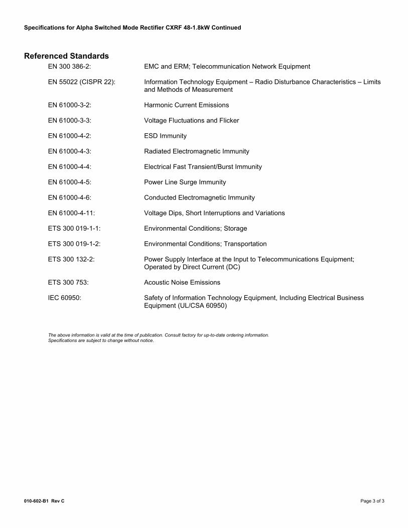
Specifications for Alpha Switched Mode Rectifier CXRF 48-1.8kW Continued
010-602-B1 Rev C Page 3 of 3
Referenced Standards EN 300 386-2: EMC and ERM; Telecommunication Network Equipment EN 55022 (CISPR 22): Information Technology Equipment – Radio Disturbance Characteristics – Limits
and Methods of Measurement EN 61000-3-2: Harmonic Current Emissions EN 61000-3-3: Voltage Fluctuations and Flicker EN 61000-4-2: ESD Immunity EN 61000-4-3: Radiated Electromagnetic Immunity EN 61000-4-4: Electrical Fast Transient/Burst Immunity EN 61000-4-5: Power Line Surge Immunity EN 61000-4-6: Conducted Electromagnetic Immunity EN 61000-4-11: Voltage Dips, Short Interruptions and Variations ETS 300 019-1-1: Environmental Conditions; Storage ETS 300 019-1-2: Environmental Conditions; Transportation ETS 300 132-2: Power Supply Interface at the Input to Telecommunications Equipment;
Operated by Direct Current (DC) ETS 300 753: Acoustic Noise Emissions IEC 60950: Safety of Information Technology Equipment, Including Electrical Business
Equipment (UL/CSA 60950) The above information is valid at the time of publication. Consult factory for up-to-date ordering information. Specifications are subject to change without notice.

Specifications for Alpha’s Switched Mode Rectifier Cordex CXRF HP 48-2kW
010-622-B2 Rev A Page 1 of 3
Power Module Output Voltage: 44 to 58Vdc within rated limits Current: 37A @ 54Vdc nominal (41.7A maximum) (~26A @ 48Vdc at 120Vac Input) Maximum Power: 2kW continuous/module @ 208/220/230/240Vac nominal (~1250W Output at 120Vac Input) Static Load Regulation: Better than ±0.5% for any load change within rated limits Dynamic Load Regulation: Better than ±2% for 40% to 90% - 40% load step change Static Line Regulation: Better than ±0.5% for any change in input voltage within rated limits Hold-up Time: >5ms Time Stability: ≤0.5% per year, under the control of the controller Temperature Stability: ≤300ppm/°C over the operating range, under the control of controller Heat Dissipation: <549BTU per hour (per rectifier module) Electrical Noise: <38dBrnC (voice band)
<30mVrms to 10MHz <150mVp-p to 100MHz <2mVrms (psophometric)
Acoustic Noise: <60dBa @ 1m (3ft.) @ 30°C (86°F), 4 fully equipped shelves EMI: The unit meets requirements of EN55022 and NEBS (designed to meet) (see
Standards for more EMC) In accordance with FCC requirements, we provide the following statement as specified in the FCC guidelines for conformance to Part 15, Class B:
NOTE: This equipment has been tested and found to comply with the limits for a Class B digital device, pursuant to part 15 of the FCC Rules. These limits are designed to provide reasonable protection against harmful interference in a residential installation. This equipment generates, uses, and can radiate radio frequency energy and, if not installed and used in accordance with the instructions, may cause harmful interference to radio communications. However, there is no guarantee that interference will not occur in a particular installation. If this equipment does cause harmful interference to radio or television reception, which can be determined by turning the equipment off and on, the user is encouraged to try to correct the interference by one or more of the following measures: • Reorient or relocate the receiving antenna. • Increase the separation between the equipment and receiver. • Connect the equipment into an outlet on a circuit different from that to which the receiver is connected. • Consult the dealer or an experienced radio/TV technician for help.
Any changes or modifications to this equipment not expressly described in this manual could void the FCC compliance.
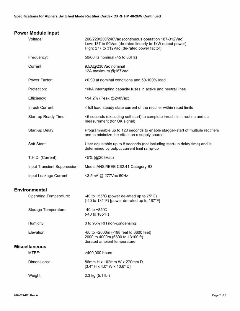
Specifications for Alpha’s Switched Mode Rectifier Cordex CXRF HP 48-2kW Continued
010-622-B2 Rev A Page 2 of 3
Power Module Input Voltage: 208/220/230/240Vac (continuous operation 187-312Vac)
Low: 187 to 90Vac (de-rated linearly to 1kW output power) High: 277 to 312Vac (de-rated power factor)
Frequency: 50/60Hz nominal (45 to 66Hz) Current: 9.5A@230Vac nominal
12A maximum @187Vac Power Factor: >0.99 at nominal conditions and 50-100% load Protection: 10kA interrupting capacity fuses in active and neutral lines Efficiency: >94.2% (Peak @240Vac) Inrush Current: ≤ full load steady state current of the rectifier within rated limits Start-up Ready Time: <5 seconds (excluding soft start) to complete inrush limit routine and ac
measurement (for OK signal) Start-up Delay: Programmable up to 120 seconds to enable stagger-start of multiple rectifiers
and to minimize the effect on a supply source Soft Start: User adjustable up to 8 seconds (not including start-up delay time) and is
determined by output current limit ramp-up T.H.D. (Current): <5% (@208Vac) Input Transient Suppression: Meets ANSI/IEEE C62.41 Category B3 Input Leakage Current: <3.5mA @ 277Vac 60Hz
Environmental Operating Temperature: -40 to +55°C (power de-rated up to 75°C)
(-40 to 131°F) [power de-rated up to 167°F] Storage Temperature: -40 to +85°C
(-40 to 185°F) Humidity: 0 to 95% RH non-condensing Elevation: -60 to +2000m (-198 feet to 6600 feet) 2000 to 4000m (6600 to 13100 ft) derated ambient temperature
Miscellaneous MTBF: >400,000 hours Dimensions: 86mm H x 102mm W x 270mm D
[3.4" H x 4.0" W x 10.6" D] Weight: 2.3 kg (5.1 lb.)
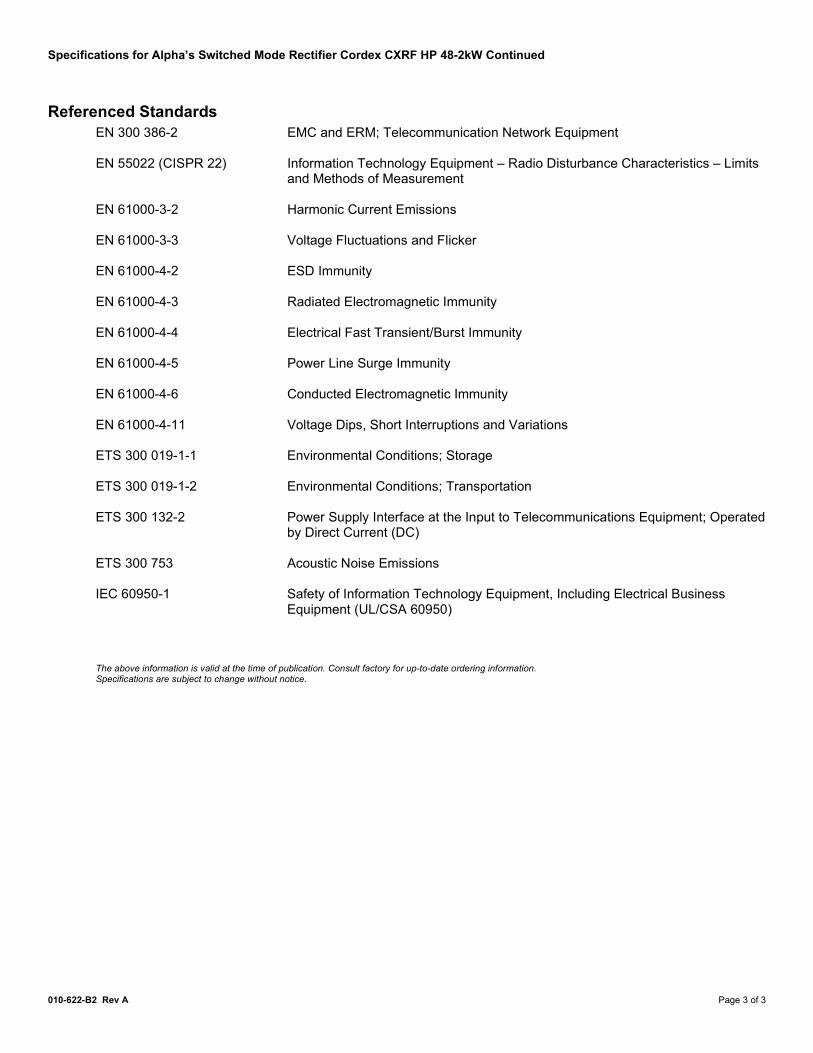
Specifications for Alpha’s Switched Mode Rectifier Cordex CXRF HP 48-2kW Continued
010-622-B2 Rev A Page 3 of 3
Referenced Standards EN 300 386-2 EMC and ERM; Telecommunication Network Equipment EN 55022 (CISPR 22) Information Technology Equipment – Radio Disturbance Characteristics – Limits
and Methods of Measurement EN 61000-3-2 Harmonic Current Emissions EN 61000-3-3 Voltage Fluctuations and Flicker EN 61000-4-2 ESD Immunity EN 61000-4-3 Radiated Electromagnetic Immunity EN 61000-4-4 Electrical Fast Transient/Burst Immunity EN 61000-4-5 Power Line Surge Immunity EN 61000-4-6 Conducted Electromagnetic Immunity EN 61000-4-11 Voltage Dips, Short Interruptions and Variations ETS 300 019-1-1 Environmental Conditions; Storage ETS 300 019-1-2 Environmental Conditions; Transportation ETS 300 132-2 Power Supply Interface at the Input to Telecommunications Equipment; Operated
by Direct Current (DC) ETS 300 753 Acoustic Noise Emissions IEC 60950-1 Safety of Information Technology Equipment, Including Electrical Business
Equipment (UL/CSA 60950) The above information is valid at the time of publication. Consult factory for up-to-date ordering information. Specifications are subject to change without notice.
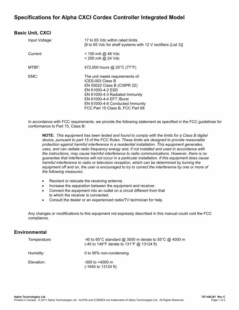
Specifications for Alpha CXCI Cordex Controller Integrated Model
Alpha Technologies Ltd. 707-492-B1 Rev C Printed in Canada. © 2011 Alpha Technologies Ltd. ALPHA and CORDEX are trademarks of Alpha Technologies Ltd. All Rights Reserved. Page 1 of 2
Basic Unit, CXCI Input Voltage: 17 to 65 Vdc within rated limits
[9 to 65 Vdc for shelf systems with 12 V rectifiers (List 3)] Current: < 100 mA @ 48 Vdc
< 200 mA @ 24 Vdc MTBF: 472,000 hours @ 25°C (77°F) EMC: The unit meets requirements of:
ICES-003 Class B EN 55022 Class B (CISPR 22) EN 61000-4-2 ESD EN 61000-4-3 Radiated Immunity EN 61000-4-4 EFT /Burst EN 61000-4-6 Conducted Immunity FCC Part 15 Class B, FCC Part 68
In accordance with FCC requirements, we provide the following statement as specified in the FCC guidelines for conformance to Part 15, Class B:
NOTE: This equipment has been tested and found to comply with the limits for a Class B digital device, pursuant to part 15 of the FCC Rules. These limits are designed to provide reasonable protection against harmful interference in a residential installation. This equipment generates, uses, and can radiate radio frequency energy and, if not installed and used in accordance with the instructions, may cause harmful interference to radio communications. However, there is no guarantee that interference will not occur in a particular installation. If this equipment does cause harmful interference to radio or television reception, which can be determined by turning the equipment off and on, the user is encouraged to try to correct the interference by one or more of the following measures: • Reorient or relocate the receiving antenna. • Increase the separation between the equipment and receiver. • Connect the equipment into an outlet on a circuit different from that
to which the receiver is connected. • Consult the dealer or an experienced radio/TV technician for help.
Any changes or modifications to this equipment not expressly described in this manual could void the FCC compliance.
Environmental Temperature: -40 to 65°C standard @ 3000 m derate to 55°C @ 4000 m
(-40 to 149°F derate to 131°F @ 13124 ft) Humidity: 0 to 95% non-condensing Elevation: -500 to +4000 m
(-1640 to 13124 ft)

Specifications for Alpha CXCI Cordex Controller Integrated Model Continued
Alpha Technologies Ltd. 707-492-B1 Rev C Printed in Canada. © 2011 Alpha Technologies Ltd. ALPHA and CORDEX are trademarks of Alpha Technologies Ltd. All Rights Reserved. Page 2 of 2
Hardware Specifications, CXCI CPU: Coldfire RAM: 8 MB Flash: 4 MB standard Display: 4 digit LCD Front Panel Controls: Display pushbutton toggle switch for voltage (V) or current (A)
CXCI reset switch (soft reset button; hold for 3 seconds to reset IP) LED’s: System OK (Green)
Power System Minor Alarm (Yellow) Power System Major Alarm / Controller Fail (Red)
Audio: Built-in speaker for alarm and popup message tones Dimensions: 88 mm H x 26 mm W x 280 mm D
(3.5" H x 1" W x 11" D) Weight: 0.34 kg (0.75 lb.) Mounting: Integrated on Cordex 2RU series 19" and 23" shelves Relay Outputs: Four (4) Form C, 60 Vdc 1A maximum Digital Inputs: Two (2), 0 to 60 Vdc Analog Inputs: One (1) DC voltage, 0 to 60 Vdc
One (1) DC current, ±50 mV Two (2) temperature, 0 to 20 Vdc with power source
Communication Ports: Ethernet RJ-45, Alpha Modem DB-9, CAN [see shelf specifications]
Recommended Signal Wire Sizes (as per UL/CSA) Wire Size Range: 0.14 to 1.50 mm2
(#26 to #16 AWG) Temperature Range: 0 to 50°C
(32 to 122°F) CAUTION – TO REDUCE RISK OF FIRE, USE ONLY 0.14 mm2 (#26 AWG) OR LARGER WIRE. The above information is valid at the time of publication. Consult factory for up-to-date ordering information. Specifications are subject to change without notice.

Specifications for Alpha CXCM2 Cordex Controller Modular 2RU Model
Alpha Technologies Ltd. 018-588-B1 Rev C Printed in Canada. © 2011 Alpha Technologies Ltd. ALPHA and CORDEX are trademarks of Alpha Technologies Ltd. All Rights Reserved. Page 1 of 2
Basic Unit, CXCM2 Input Voltage: 17 to 65 Vdc within rated limits Current: < 100mA @ 48 Vdc
< 200mA @ 24 Vdc MTBF: > 430,000 hours @ 30°C (86°F) EMC: The unit meets requirements of:
ICES-003 Class B EN 55022 Class B (CISPR 22) EN 61000-4-2 ESD EN 61000-4-3 Radiated Immunity EN 61000-4-4 EFT /Burst EN 61000-4-6 Conducted Immunity FCC Part 15 Class B, FCC Part 68
In accordance with FCC requirements, we provide the following statement as specified in the FCC guidelines for conformance to Part 15, Class B:
NOTE: This equipment has been tested and found to comply with the limits for a Class B digital device, pursuant to part 15 of the FCC Rules. These limits are designed to provide reasonable protection against harmful interference in a residential installation. This equipment generates, uses, and can radiate radio frequency energy and, if not installed and used in accordance with the instructions, may cause harmful interference to radio communications. However, there is no guarantee that interference will not occur in a particular installation. If this equipment does cause harmful interference to radio or television reception, which can be determined by turning the equipment off and on, the user is encouraged to try to correct the interference by one or more of the following measures: • Reorient or relocate the receiving antenna. • Increase the separation between the equipment and receiver. • Connect the equipment into an outlet on a circuit different from that
to which the receiver is connected. • Consult the dealer or an experienced radio/TV technician for help.
Any changes or modifications to this equipment not expressly described in this manual could void the FCC compliance.
Environmental Temperature: -40 to 65°C standard @ 3000 m, derate to 55°C @ 4000 m
(-40 to 149°F, derate to 131°F @ 13124 ft) Humidity: 0 to 95% non-condensing Elevation: -500 to +4000 m
(-1640 to 13124 ft)
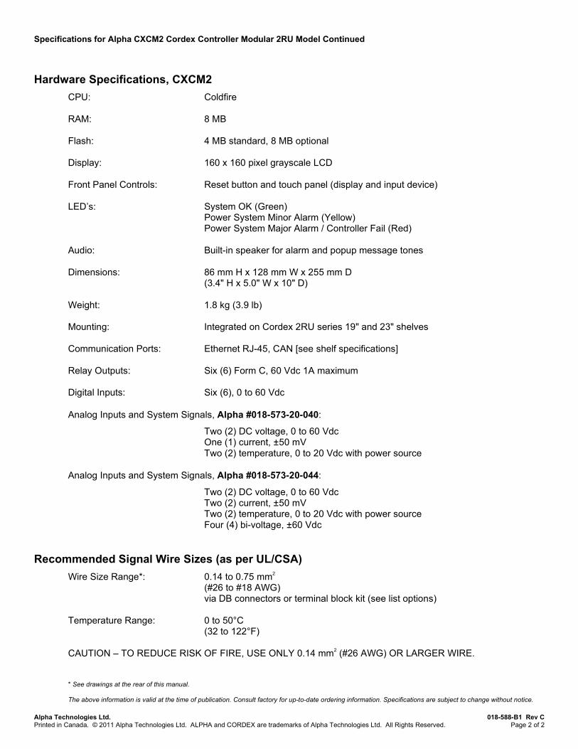
Specifications for Alpha CXCM2 Cordex Controller Modular 2RU Model Continued
Alpha Technologies Ltd. 018-588-B1 Rev C Printed in Canada. © 2011 Alpha Technologies Ltd. ALPHA and CORDEX are trademarks of Alpha Technologies Ltd. All Rights Reserved. Page 2 of 2
Hardware Specifications, CXCM2 CPU: Coldfire RAM: 8 MB Flash: 4 MB standard, 8 MB optional Display: 160 x 160 pixel grayscale LCD Front Panel Controls: Reset button and touch panel (display and input device) LED’s: System OK (Green)
Power System Minor Alarm (Yellow) Power System Major Alarm / Controller Fail (Red)
Audio: Built-in speaker for alarm and popup message tones Dimensions: 86 mm H x 128 mm W x 255 mm D
(3.4" H x 5.0" W x 10" D) Weight: 1.8 kg (3.9 lb) Mounting: Integrated on Cordex 2RU series 19" and 23" shelves Communication Ports: Ethernet RJ-45, CAN [see shelf specifications] Relay Outputs: Six (6) Form C, 60 Vdc 1A maximum Digital Inputs: Six (6), 0 to 60 Vdc Analog Inputs and System Signals, Alpha #018-573-20-040:
Two (2) DC voltage, 0 to 60 Vdc One (1) current, ±50 mV Two (2) temperature, 0 to 20 Vdc with power source
Analog Inputs and System Signals, Alpha #018-573-20-044:
Two (2) DC voltage, 0 to 60 Vdc Two (2) current, ±50 mV Two (2) temperature, 0 to 20 Vdc with power source Four (4) bi-voltage, ±60 Vdc
Recommended Signal Wire Sizes (as per UL/CSA) Wire Size Range*: 0.14 to 0.75 mm2
(#26 to #18 AWG) via DB connectors or terminal block kit (see list options)
Temperature Range: 0 to 50°C
(32 to 122°F) CAUTION – TO REDUCE RISK OF FIRE, USE ONLY 0.14 mm2 (#26 AWG) OR LARGER WIRE. * See drawings at the rear of this manual. The above information is valid at the time of publication. Consult factory for up-to-date ordering information. Specifications are subject to change without notice.

Specifications for Alpha CXRF 48-1.8/2.0kW 23" Shelf
Alpha Technologies Ltd. 030-807-B1 Rev C WC Printed in Canada. © 2008 Alpha Technologies Ltd. ALPHA and CORDEX are trademarks of Alpha Technologies Ltd. All Rights Reserved.
Basic Unit, Shelf Maximum Output: 187.5 A (five modules) @ 48 Vdc (nominal AC input) Recommended Feeder Breaker Single Phase: 120V or 240 V, 50 A, #6AWG (three module feed) 120V or 240 V, 30 A, #10AWG (two module feed)
Mechanical Dimensions: 88.4 mm H x 584 mm W x 304 mm D (rectifier front panel 20 mm D)
[3.48" H x 23.0" W x 12.0" D (rectifier front panel 0.8" D)] Mounting*: 23" rack (flush or 6" offset) Weight: 10 kg (22.1 lb)
Connections AC input: Dual feed (mini-fit connectors or terminal blocks, see list options) Chassis Ground: 1/4-20 x 5/8" lugs Communications: CAN (bus) RJ-12 offset DC Output: 3/8-16 x 1" lugs Signal Wiring*: 0.14 to 0.75 mm2 (#26 to #18 AWG)
via DB connectors or terminal block kit (see list options)
Safety EN 60950: Rectifier output shall be rated SELV suitable for connection to TNV-1 circuits UL: 60950-1-2002 CSA: C22.2 No. 60950 CE: EN 60950, CB Scheme
73/23/EEC Low Voltage Directive with amendment 93/68/EEC Telcordia (Bellcore): GR-1089-CORE (requirements applicable to rectifier) * See drawings at the rear of this manual. The above information is valid at the time of publication. Consult factory for up-to-date ordering information. Specifications are subject to change without notice.

Specifications for Alpha Cordex 48-1.8/2.0kW 19" Shelf
Alpha Technologies Ltd. 030-809-B1 Rev C Printed in Canada. © 2011 Alpha Technologies Ltd. ALPHA and CORDEX are trademarks of Alpha Technologies Ltd. All Rights Reserved. Page 1 of 1
Basic Unit, Shelf Maximum Output: 150A (four modules) @ 48Vdc (nominal AC input) Recommended Feeder Breaker (Single Phase) Individual Feeds: 120V or 240V, 15A, #14AWG (per individual rectifier) Dual Feeds: 30A, 120V or 240V, #10AWG (per rectifier pair)
Mechanical Dimensions: 88.4mm H x 481mm W x 304mm D (rectifier front panel 20mm D)
[3.48" H x 18.9" W x 12.0" D (rectifier front panel 0.8” D)] Mounting*: 19" rack (flush or 6" offset) Weight: 8.5 kg (18.7 lb.)
Connections AC input: Individual feed terminal blocks. Optional AC input terminal block configuration to feed two modules each side of
the shelf. Chassis Ground: 1/4-20 x 5/8" lugs Communications: CAN (bus) RJ-12 offset DC Output: 3/8-16 x 1" lugs Signal Wiring*: 0.14 to 0.75mm2 (#26 to #18 AWG)
via DB connectors or terminal block kit (see list options)
Safety EN 60950: Rectifier output shall be rated SELV suitable for connection to TNV-1 circuits UL: 60950-1-2002 CSA: C22.2 No. 60950 CE: EN 60950, CB Scheme
73/23/EEC Low Voltage Directive with amendment 93/68/EEC Telcordia (Bellcore): GR-1089-CORE (requirements applicable to rectifier) * See drawings at the rear of this manual. The above information is valid at the time of publication. Consult factory for up-to-date ordering information. Specifications are subject to change without notice.

c 2009 ARGUS TECHNOLOGIES
LIST 84
LIST 91 -CONTROLLER BLANKCORDEX 48-1.8kW
RECTIFIERS ONLY OPTION
010-602-20 POWER MODULE,
LIST 24 - 6"OFFSET
2009/02
NTS
SIZE DWG NO.TYPE
B
SHEET
TITLE
ISSUE
DATEOF
TOLERANCES
SCALE
APPROVED
CHECKED
DRAWN
DESIGN MATERIAL
FINISH
FOR MANUFACTURING WITHOUT ITS WRITTEN CONSENT.ARGUS TECHNOLOGIES AND SHALL NOT BE COPIED OR USEDTHESE DESIGNS AND SPECIFICATIONS ARE THE PROPERTY OF
REVISIONS
LTR DESCRIPTION APPDDATE
2005/05
2009/06
2005/05
A
RP
D2
X.XXX
5 MODULE, 48-1.8kW CXRF
0.01"0.02"0.04"
REV
X.XX0.25mm
X.X
030-807-06
OUTLINE, SHELF, 23",
1 3
RP
[X] 1mm[X.X] 0.5mm[X.XX]
REV BY
CXCI CONTROLLER OPTIONLIST 99 - CXCI CONTROLLER
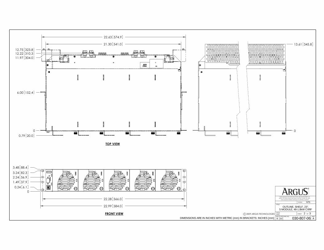
c 2009 ARGUS TECHNOLOGIES
22.28 566.0
00.24 6.1
1.49 37.92.24 56.93.24 82.33.48 88.4
0
6.00 152.4
11.97 304.012.22 310.312.75 323.8
22.63 574.9
0.79 20.0
FRONT VIEW
22.99 584.0
SIZE DWG NO.TYPE
B
SHEET
TITLE
ISSUE
DATEOF
SCALE
FOR MANUFACTURING WITHOUT ITS WRITTEN CONSENT.ARGUS TECHNOLOGIES AND SHALL NOT BE COPIED OR USEDTHESE DESIGNS AND SPECIFICATIONS ARE THE PROPERTY OF
REV
030-807-06
OUTLINE, SHELF, 23",5 MODULE, 48-1.8kW CXRF
2 3
D2 ADIMENSIONS ARE IN INCHES WITH METRIC (mm) IN BRACKETS: INCHES [mm]
NTS
TOP VIEW
21.30 541.0
0
13.61 345.8

c 2009 ARGUS TECHNOLOGIES
05.71
145.
06.
1515
6.2
7.15
181.
67.
5919
2.8
13.7
134
8.2
14.1
535
9.4
15.1
538
4.8
15.5
939
6.0
0
0.26 6.60.70 17.8
1.78 45.2
3.01 76.5
SIZE DWG NO.TYPE
B
SHEET
TITLE
ISSUE
DATEOF
SCALE
FOR MANUFACTURING WITHOUT ITS WRITTEN CONSENT.ARGUS TECHNOLOGIES AND SHALL NOT BE COPIED OR USEDTHESE DESIGNS AND SPECIFICATIONS ARE THE PROPERTY OF
REV
030-807-06
OUTLINE, SHELF, 23",5 MODULE, 48-1.8kW CXRF
3 3
D2 ADIMENSIONS ARE IN INCHES WITH METRIC (mm) IN BRACKETS: INCHES [mm]
NTS
REAR VIEW
0.63 15.9 0.63 15.9
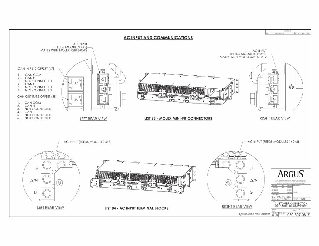
������������� ������� � ���� ����� ���
�
����
� ��
������� � ��
��������
�����
��������
�������
����
����� �� �����
�����
������������������������������� ������ �������� ������� ����������������� ����� ������ ��� � �� ����������� �������������� ��� ����� ������
� �������
��� � ��������� �������
���
��� ��������� ���������� ��� �
!�" ##!���" ��$##!����" ���$##
�%�&'�(&�'
��� �������� ���%�)$���)�'& �'*�����
%
��
��
���$+�$
���$+�$
�� �
���,+�-
���,+�-
�
� ����
������������������������
���������� �!������������������
�����#������������������� �� �$�
��%�
�&'�&
'(
� ���� ����� �
��� ���������� �����&)���&�*� ������� ���+/:
�������
&
��������'&������ ��*'(:
�������&���������������� �� �
)� �������� �� �/� �������� �� ��� �������
��������'&������ ��*'�:
�������&���������������� �� ������������������ �� �/��������� �� �)�
��%�
�&
������ ����� �
�������*� ������� ��&+�+�:
��� ���������� �����&)���&�
�&
��%�
������ ����� �
��������*� ������� ��&+�+�:
��%�
�&
� ���� ����� �
��������*� ������� ���+/:

������������� ������� �
� ������ �
�� �
��
�������������
��� ��� ��������&�����������������/����)����(������
��
���� ����� ���
�
����
� ��
������� � ��
�����
������������������������������� ������ �������� ������� ����������������� ����� ������ ��� � �� ����������� �������������� ��� ����� ������
����%�&'�(&�'
��� �������� ���%�)$���)�'& �'*�����
�%
�� �
�
�������� �
����� ���������'�� �
�%�;�&)<�%�;��=<��>?@JQZ[�\QJ]=^J�*J_``?a=[:
&%�;���<&%�;��=<��>?@JQZ[�\QJ]=^J�*J_``?a=[:
� ���� �*�:��������� ������� �*+:���������
������������������ ������!������� ��
� ����� �
���������/
�&����&��&�������������������������/�������)��&�&(����&���&+���&+&����+&&��&+&����������&���&���&�������&/������&)�������&(������&�������&���&����������&��&�����&�����������&��/�
&
�/
�� �� ���'�/
��+&��������+���������� �� ����������� �� �/����)��������� �� �(��������� �� ���
�
&
�������� �
&�
������������� ������� ����� ����� ���
�
����
� ��
������� � ��
�����
������������������������������� ������ �������� ������� ����������������� ����� ������ ��� � �� ����������� �������������� ��� ����� ������
����%�&'�(&�'
��� �������� ���%�)$���)�'& �'*�����
%%
�� �
�
&
&
'/'�'�
� &/
�/
�/����������/�&/��&+)��&����(��)�����/����
������)������(��������
�������������� ��������
&�� �������� �� �&�� ���&&&� ���&&�� ���&�� �&�&�� �&�(� ���)� ���/� ����� ����� �&��� �&�&� ���
��������������������������/�*'�:
�)�������/���&��
&/� ������&�� �����&�� �����&�� ������&&� �/���
� ������������&/�*'/:
�)���&��)������/������������������/�
���� ����� ���� ����*'�:
�&�&��&������&������)�&��
&��������+&/������&+&)������&+&(�������+&��������+&��������+���������+�&������&+��������&������������������������
&
�%�;�&)<�%�;��=<��>?@JQZ[�\QJ]=^J�*J_``?a=[:
&%�;���<&%�;��=<��>?@JQZ[\QJ]=^J�*J_``?a=[:
� ���� �*�:���������������� �*+:���������
#�������� ������!�������b��� ����� ��
� ����� �
�������� �� ���
�������� �
�� �� ���'�/
��+&��������+���������� �� ����������� �� �/����)��������� �� �(�
&
�
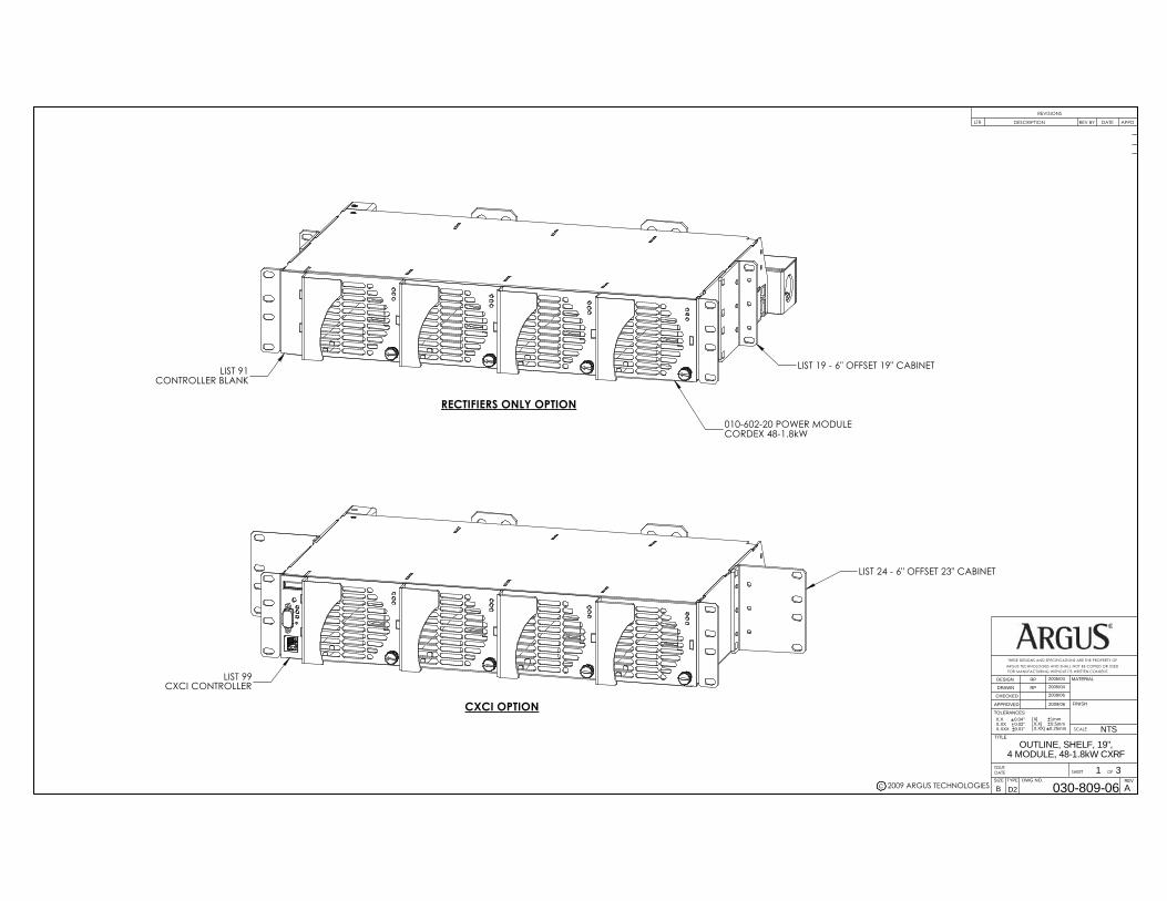
c 2009 ARGUS TECHNOLOGIES
CXCI OPTION
LIST 99CXCI CONTROLLER
LIST 24 - 6" OFFSET 23" CABINET
SIZE DWG NO.TYPE
B
SHEET
TITLE
ISSUEDATE OF
TOLERANCES
SCALE
APPROVED
CHECKED
DRAWN
DESIGN MATERIAL
FINISH
FOR MANUFACTURING WITHOUT ITS WRITTEN CONSENT.ARGUS TECHNOLOGIES AND SHALL NOT BE COPIED OR USEDTHESE DESIGNS AND SPECIFICATIONS ARE THE PROPERTY OF
REVISIONS
LTR DESCRIPTION APPDDATE
REV
X.X 0.04"X.XX 0.02"X.XXX 0.01"
[X] 1mm[X.X] 0.5mm[X.XX] 0.25mm
030-809-06
OUTLINE, SHELF, 19",4 MODULE, 48-1.8kW CXRF
1 3
RP
RP
2005/04
2005/04
D2 A
2009/06
2009/06
NTS
REV BY
LIST 91CONTROLLER BLANK
010-602-20 POWER MODULECORDEX 48-1.8kW
RECTIFIERS ONLY OPTION
LIST 19 - 6" OFFSET 19" CABINET

c 2009 ARGUS TECHNOLOGIES
0
11.97 304.012.22 310.3
0.79 20.0
6.00 152.4
12.75 323.8
18.31 - 19" CABINET465.0
00.24 6.1
1.24 31.5
1.99 50.6
3.24 82.3
2.24 56.9
1.49 37.9
3.48 88.4
22.31 - 23" CABINET566.7
SIZE DWG NO.TYPE
B
SHEET
TITLE
ISSUE
DATEOF
SCALE
FOR MANUFACTURING WITHOUT ITS WRITTEN CONSENT.ARGUS TECHNOLOGIES AND SHALL NOT BE COPIED OR USEDTHESE DESIGNS AND SPECIFICATIONS ARE THE PROPERTY OF
REV
030-809-06
OUTLINE, SHELF, 19",4 MODULE, 48-1.8kW CXRF
2 3
D2 ADIMENSIONS ARE IN INCHES WITH METRIC (mm) IN BRACKETS: INCHES [mm]
NTS
TOP VIEW
17.24 438.0
18.61 472.7
FRONT VIEW
18.9 - 19" CABINET481
23.0 - 23" CABINET584
0
13.27 337.0
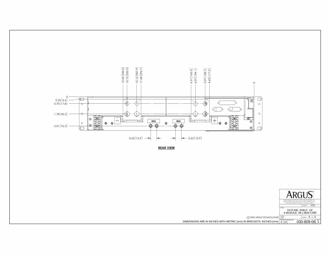
c 2009 ARGUS TECHNOLOGIES
00.26 6.6
0.70 17.8
1.78 45.2
04.63
117.
55.
0712
8.7
6.07
154.
16.
5116
5.3
11.6
829
6.7
12.1
230
7.9
13.1
233
3.3
13.5
634
4.5
3.01 76.5
SIZE DWG NO.TYPE
B
SHEET
TITLE
ISSUE
DATEOF
SCALE
FOR MANUFACTURING WITHOUT ITS WRITTEN CONSENT.ARGUS TECHNOLOGIES AND SHALL NOT BE COPIED OR USEDTHESE DESIGNS AND SPECIFICATIONS ARE THE PROPERTY OF
REV
030-809-06
OUTLINE, SHELF, 19",4 MODULE, 48-1.8kW CXRF
3 3
D2 ADIMENSIONS ARE IN INCHES WITH METRIC (mm) IN BRACKETS: INCHES [mm]
NTS
REAR VIEW
0.63 15.90.63 15.9

©
NAME DATE
APPROVED
CHECKED
DRAWN
DESIGN 2005/11
2005/11
2009/06
2009/06
RP
RP
JK
GIA
SCALE:
THESE DESIGNS AND SPECIFICATIONS ARE CONFIDENTIAL, REMAINTHE PROPERTY OF ALPHA TECHNOLOGIES LTD., AND SHALL NOT
BE COPIED OR USED WITHOUT ITS WRITTEN CONSENT.
TYPE
0.5
D2
10.50.05 0.002]
[ 0.040] [ 0.020] [
UNITS: mm [in] X [X.X] X.X [X.XX] X.XX [X.XXX] ANGULAR:
OF
2010 ALPHA TECHNOLOGIES
TITLE:
ISSUEDATESIZEB
DWG NO.
CUSTOMER CONNECTION, 19", 4 MDL, 48-1.8kW CXRF
030-809-08SHEET
NTS
REVB
1 3
MP2011/05WH JKEO 030-809-K0-C1, EO 10790BLTR APPDATEDRW
REVISIONSDESCRIPTION CHK
1
CAN OUT RJ12 OFFSET (J8)
CAN COM1.CAN H2.NOT CONNECTED3.CAN L4.NOT CONNECTED
J8
J7
6. NOT CONNECTED5.
CAN IN RJ12 OFFSET (J7)
CAN COM1.CAN H2.NOT CONNECTED3.CAN L4.NOT CONNECTED5.NOT CONNECTED6.
1
L2/N
L1
L2/N
L1
(FEEDS MODULE 2)AC INPUT
AC INPUT LIST 84
AC INPUT(FEEDS MODULE 1)
AC INPUT(FEEDS MODULE 3)
L1L2/N
REAR VIEW
L1L2/N
AC INPUT(FEEDS MODULE 4)
RIGHT SIDE VIEW
COMMUNICATIONS
L2/N
L1
AC INPUT(FEEDS MODULES 3 & 4)
L2/N
L1
AC INPUT LIST 85
AC INPUT(FEEDS MODULES 1 & 2)
©

©
SCALE:
THESE DESIGNS AND SPECIFICATIONS ARE CONFIDENTIAL, REMAINTHE PROPERTY OF ALPHA TECHNOLOGIES LTD., AND SHALL NOT
BE COPIED OR USED WITHOUT ITS WRITTEN CONSENT.
TYPE
0.5
D2
10.50.05 0.002]
[ 0.040] [ 0.020] [
UNITS: mm [in] X [X.X] X.X [X.XX] X.XX [X.XXX] ANGULAR:
OF
2010 ALPHA TECHNOLOGIES
TITLE:
ISSUEDATESIZEB
DWG NO.
CUSTOMER CONNECTION, 19", 4 MDL, 48-1.8kW CXRF
030-809-08SHEET
NTS
REVB
2 3
OPEN
TERMINATED
3.DTR4.COM5.DSR6.RTS7.CTS8.RI
DB9FOR ARGUS DC
MODEM USE ONLY
DCD1.RX2.TX
9.
L1
REAR VIEW
L2/N
L2/N
L1
LIST 99 - 4 POWER MODULES + CXCI CONTROLLER
and washers (supplied)1/4"-20x1/2" Hex Bolts
NEGATIVE (-) OUTPUT BAR
L2/N
POSITIVE (+) OUTPUT BAR
and washers (supplied)3/8"-16x3/4" Hex Bolts
L1
L2/N
L1
25.
1
CXCI DB-25
K1-COM1.K1-NC2.K2-COM3.K3-NC4.K3-NO5.K4-COM6.D1-17.D2-18.V1+9.T1+10.T2+11.I1+12.BATT HOT13.K1-NO14.K2-NC15.K2-NO16.K3-COM17.K4-NO18.K4-NC19.D1-220.D2-221.V1-22.T1-23.T2-24.I1-
25
CAN TERMINATIONJUMPER
9
FRONT VIEW8. NOT CONNECTED
1
ETHERNET RJ45
TX+1.TX-2.RX+3.NOT CONNECTED4.NOT CONNECTED5.RX-6.NOT CONNECTED7.
8
1
FRONT VIEW
©
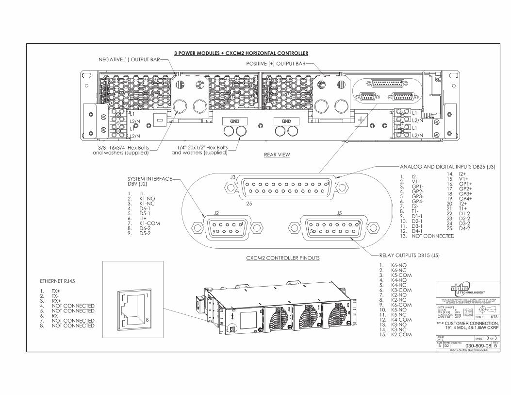
©
SCALE:
THESE DESIGNS AND SPECIFICATIONS ARE CONFIDENTIAL, REMAINTHE PROPERTY OF ALPHA TECHNOLOGIES LTD., AND SHALL NOT
BE COPIED OR USED WITHOUT ITS WRITTEN CONSENT.
TYPE
0.5
D2
10.50.05 0.002]
[ 0.040] [ 0.020] [
UNITS: mm [in] X [X.X] X.X [X.XX] X.XX [X.XXX] ANGULAR:
OF
2010 ALPHA TECHNOLOGIES
TITLE:
ISSUEDATESIZEB
DWG NO.
CUSTOMER CONNECTION, 19", 4 MDL, 48-1.8kW CXRF
030-809-08SHEET
NTS
REVB
3 3
REAR VIEW
NOT CONNECTED8.
ETHERNET RJ45
TX+1.TX-2.RX+3.NOT CONNECTED4.NOT CONNECTED5.RX-6.NOT CONNECTED7.
1
8
1
25. D4-2
J2 J5
GP1-
14. K3-NC13. K3-NO12. K4-COM
5. GP3-4. GP2-
11.
9
6.K1-COM7.
D5-2
V1-1. I2-
ANALOG AND DIGITAL INPUTS DB25 (J3)
D6-28.
J3
K5-NC
GP4-6.T2-7.T1-8.D1-19.D2-110.D3-111.D4-112.NOT CONNECTED13.
K2-COM
9.
2.
25
15.
CXCM2 CONTROLLER PINOUTS
3.SYSTEM INTERFACEDB9 (J2)
I1-1.K1-NO2.K1-NC3.D6-14.D5-15.I1+
RELAY OUTPUTS DB15 (J5)
K6-NO1.K6-NC2.K5-COM3.K4-NO4.K4-NC5.K3-COM6.K2-NO7.K2-NC8.K6-COM9.K5-NO10.
14. I2+15. V1+16. GP1+17. GP2+18. GP3+19. GP4+20. T2+21. T1+22. D1-223. D2-224. D3-2
15
POSITIVE (+) OUTPUT BAR
3/8"-16x3/4" Hex Bolts 1/4"-20x1/2" Hex Bolts
L2/N
and washers (supplied)
3 POWER MODULES + CXCM2 HORIZONTAL CONTROLLERNEGATIVE (-) OUTPUT BAR
L2/NL1
and washers (supplied)
L1
L2/N
L1L2/NL1
©

048-554-00 Rev D
CertificationWhat are the CSA and NRTL?
CSA (Canadian Standards Association also known as CSA International) was established in 1919 as an independent testing laboratory in Canada. CSA received its recognition as an NRTL (Nationally Recognized Testing Laboratory) in 1992 from OSHA (Occupational Safety and Health Administration) in the United States of America (Docket No. NRTL-2-92). This was expanded and renewed in 1997, 1999, and 2001. The specifi c notifi cations were posted on OSHA’s offi cial website as follows:
■ Federal Register #: 59:40602 - 40609 [08/09/1994]
■ Federal Register #: 64:60240 - 60241 [11/04/1999]
■ Federal Register #: 66:35271 - 35278 [07/03/2001]
When these marks appear with the indicator “C and US” or “NRTL/C” it means that the product is certifi ed for both the US and Canadian markets, to the applicable US and Cana-dian standards. (1)
Alpha rectifi er and power system products, bearing the aforementioned CSA marks, are certifi ed to CSA C22.2 No. 950 and UL 1950, or CSA/UL 60950.
As part of the reciprocal, US/Canada agreement regarding testing laboratories, the Stan-dards Council of Canada (Canada’s national accreditation body) granted Underwriters Laboratories (UL) authority to certify products for sale in Canada. (2)
Only Underwriters Laboratories may grant a licence for the use of this mark, which indicates compliance with both Canadian and US requirements. (3)
What are NRTLs and what do they do?
NRTLs are third party organizations recognized by OSHA, US Department of Labor, under the NRTL pro-gram.
The testing and certifi cations are based on product safety standards developed by US based standards developing organizations and are often issued by the American National Standards Institute (ANSI). (4)
The NRTL determines that a product meets the requirements of an appropriate consensus-based product safety standard either by successfully testing the product itself, or by verifying that a contract laboratory has done so, and the NRTL certifi es that the product meets the requirements of the product safety standard. (4)
When was the NRTL started and who governs it?
In 1983, in a suit brought on by an independent testing laboratory, OSHA was court ordered to remove specifi c references to UL (Underwriters Labo-ratories) and FMRC (Factory Mutual Research Corporation) from its regula-tions.
In 1988, OSHA revised its regulations to remove those references and the NRTL program was established.
The NRTL Program is both national and international in scope with foreign labs permitted.


Visit us at www.alpha.ca
Due to continuing product development, Alpha Technologies reserves the right to change specifications without notice. Copyright © 2011 Alpha Technologies. All Rights Reserved. Alpha® is a registered trademark of Alpha Technologies.
Alpha Technologies Ltd.7700 Riverfront GateBurnaby, BC V5J 5M4 CanadaTel: +1 604 436 5900Fax: +1 604 436 1233Toll Free: +1 800 667 8743
Alpha Technologies Inc.3767 Alpha WayBellingham, WA 98226 United StatesTel: +1 360 647 2360Fax: +1 360 671 4936
Alpha Industrial Power Inc.1075 Satellite Blvd NW, Suite 400Suwanee, GA 30024 United StatesTel: +1 678 475 3995Fax: +1 678 584 9259
Alpha Energy1628 W Williams DrivePhoenix, AZ 85027 United StatesTel: +1 602 997 1007Fax: +1 623 249 7833
Alpha Technologies GmbHHansastrasse 8D-91126Schwabach, GermanyTel: +49 9122 79889 0Fax: +49 9122 79889 21
Technologies Argus First de MexicoAnatole France Num. 17 Colonia Polanco11560, México D.F. Tel: +52 55 5280 6990
Alpha Technologies Europe Ltd.Twyford House ThorleyBishop’s StortfordHertfordshire, CM22 7PA United KingdomTel: +44 1279 501110Fax: +44 1279 659870
Alphatec Ltd.339 St. Andrews St. Suite 101 Andrea ChambersP.O. Box 564683307 Limassol, CyprusTel: +357 25 375 675Fax: +357 25 359 595
Alpha TEK oooKhokhlovskiy Pereulok 16Stroenie 1, Office 403Moscow, 109028 RussiaTel: +7 495 916 1854Fax: +7 495 916 1349
Alpha TechnologiesUnit 504, 5/F, Fourseas BuildingNo 208-212 Nathan RoadKowloon, Hong KongTel: +852 2736 8663Fax: +852 2199 7988
Alpha Innovations BrasilRua Manuel Augusto de Alvarenga, 155São Paulo, SP - BrasilTel: +55 11 2476 0150Fax: +55 11 2476 0150
Alphatec BalticS. Konarskio Street 49-201Vilnius, LT-03123 LithuaniaTel: +370 5 210 5291Fax: +370 5 210 5292