alpha technologies - guiding principles - alpha xm 360 · designed for xm2-300hp power supply ......
TRANSCRIPT

Transponder Review July 12, 2013

Agenda
➤Transponder Overview
– Hardware
– Local Access
– Data Flow
• Diagnostic Scenarios – Common Problems
• Questions and Answers

DSM3 Transponders Summary
FEATURES DPM DSM3 DSM3X
DOCSIS 2.0, ANSI/SCTE HMS compatible
Local /Remote Diagnostics via Web Interface
Broadcom CM chipset
Supports XM2 and XM3
Single IP and Dual-IP Operation
Harness Installation and RF Level Indicators
Maximum number of batteries monitored 1 2 x 3,4 4 x 3,4
External Equipment Monitoring
AlphaGen Monitoring Support
Designed for XM2-300HP Power Supply
XM3 Smart Harness Voltage Sensing DPM DSM3 DSM3X
MODEL

DSM3 Series Features
Angled F-connector
Local & Remote
Web Access
“Battery Harness Installed” LED,
Up to 4 battery strings
Also supports 6 Volt x 6 Battery Configuration
RF Level
External Monitor
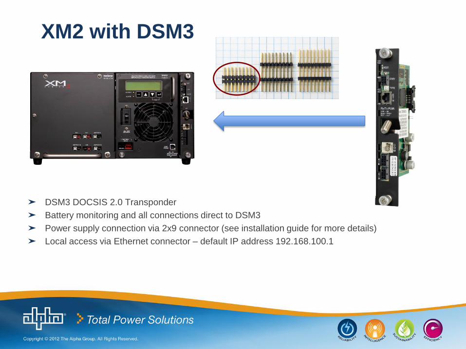
XM2 with DSM3
➤ DSM3 DOCSIS 2.0 Transponder
➤ Battery monitoring and all connections direct to DSM3
➤ Power supply connection via 2x9 connector (see installation guide for more details)
➤ Local access via Ethernet connector – default IP address 192.168.100.1

XM3 with DSM3
➤ DSM3 for XM3 DOCSIS 2.0 Transponder
➤ Same transponder as DSM3 for XM2 except for front panel
➤ Connects to XM3 via 2x9 interface (See Quick Start Guide for details)
➤ Details next slides…
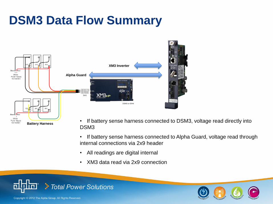
• If battery sense harness connected to DSM3, voltage read directly into
DSM3
• If battery sense harness connected to Alpha Guard, voltage read through
internal connections via 2x9 header
• All readings are digital internal
• XM3 data read via 2x9 connection
DSM3 or IDH4
SAG
Battery Harness
DSM3 Data Flow Summary
XM3 Inverter
Alpha Guard

IDH4 Series Overview
FEATURES IDH4L IDH4 IDH4X
DOCSIS 2.0, ANSI/SCTE HMS compatible
SNMP, Web and Ethernet Craft Access
Single image firmware
Supports XM2 and XM3 smart display
Single module supports one-IP and dual-IP
Harness Installation and RF Level Indicators
Maximum number of batteries monitored 1 2 x 3,4 4 x 3,4
External equipment monitoring and control
Multiple XM2 or XM3 and AlphaGen Support
Designed for XM2-300HP Power Supply
XM3 Smart Harness Voltage Sensing IDH4L IDH4 IDH4X
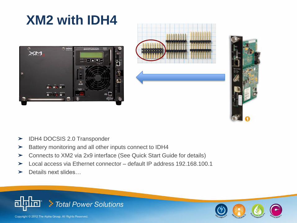
XM2 with IDH4
➤ IDH4 DOCSIS 2.0 Transponder
➤ Battery monitoring and all other inputs connect to IDH4
➤ Connects to XM2 via 2x9 interface (See Quick Start Guide for details)
➤ Local access via Ethernet connector – default IP address 192.168.100.1
➤ Details next slides…

XM2 with IDH3
➤ IDH3 DOCSIS 2.0 Transponder
➤ Data flow: Power supply (2x9) to EDSM (ribbon cable) to IDH3
➤ EDSM Function: – Converts proprietary data format to SCTE standard format
– Inputs for battery voltage, tamper and AlphaBus
• Local access via Ethernet connector – default IP address 192.168.100.1
EDSM Card
IDH3 Transponder
Either
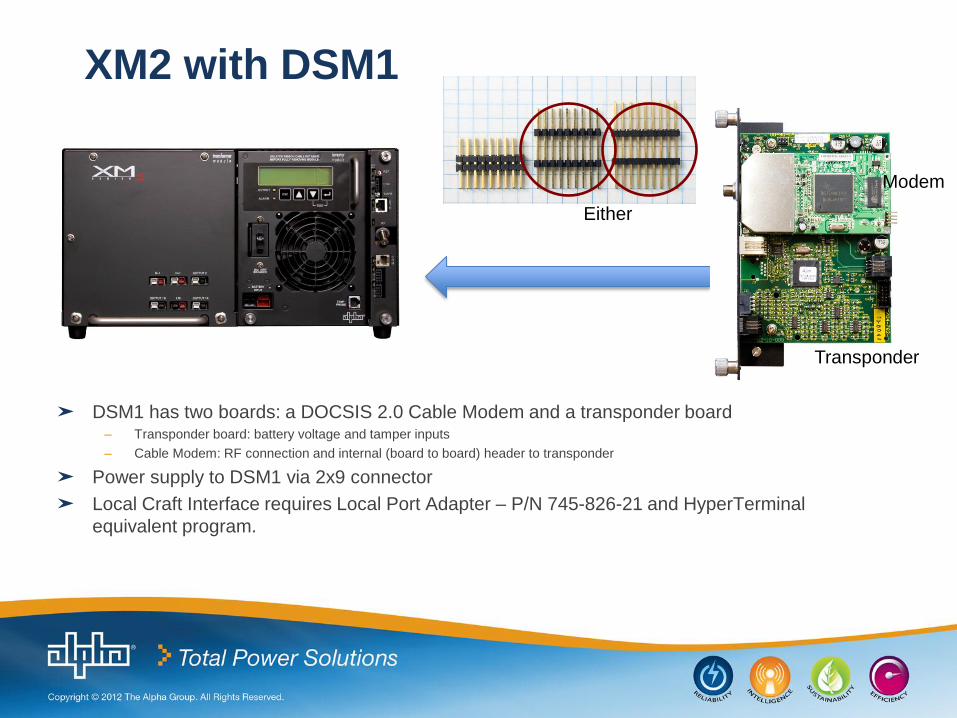
XM2 with DSM1
➤ DSM1 has two boards: a DOCSIS 2.0 Cable Modem and a transponder board – Transponder board: battery voltage and tamper inputs
– Cable Modem: RF connection and internal (board to board) header to transponder
➤ Power supply to DSM1 via 2x9 connector
➤ Local Craft Interface requires Local Port Adapter – P/N 745-826-21 and HyperTerminal
equivalent program.
Either
Modem
Transponder
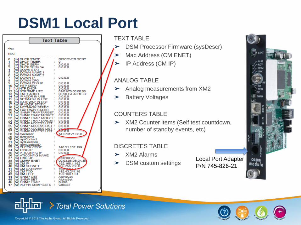
DSM1 Local Port TEXT TABLE
➤ DSM Processor Firmware (sysDescr)
➤ Mac Address (CM ENET)
➤ IP Address (CM IP)
ANALOG TABLE
➤ Analog measurements from XM2
➤ Battery Voltages
COUNTERS TABLE
➤ XM2 Counter items (Self test countdown,
number of standby events, etc)
DISCRETES TABLE
➤ XM2 Alarms
➤ DSM custom settings
Local Port Adapter
P/N 745-826-21

XM1 with EDH4
➤ XM requires USM Card. USM to EDH4 connection via wire harness
➤ Battery monitoring connects directly to EDH4
➤ Tamper connects to USM
➤ Local access via Ethernet connector – default IP address 192.168.100.1
➤ XM Series MicroController Comm Kit - Part Number 745-698-20 includes XM MCU, USM MCU, USM Bracket, and
Instructions.
– The XM MCU (Inverter Board) – minimum version required for status monitoring • Part Number 367-204-10-001 Rev. P11 or Part Number 367-204-10-002 Version 1.11
• Refer to Alpha Tech Note 017-039-C1-001 Rev. A for removal and installation
– The USM card – minimum version required for status monitoring • Part Number 367-205-10-104 Version 1.04
• Refer to Alpha Tech Note 017-039-C1-001 Rev. A for removal and installation
• Important: Select the power supply model via the Config menu on the transponder Web Page
Batteries
USM
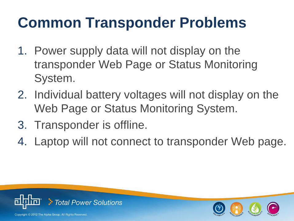
Common Transponder Problems
1. Power supply data will not display on the
transponder Web Page or Status Monitoring
System.
2. Individual battery voltages will not display on the
Web Page or Status Monitoring System.
3. Transponder is offline.
4. Laptop will not connect to transponder Web page.

1. Power Supply Data Will Not Display Possible Troubleshooting Steps:
➤Verify Device Address is set on the Inverter Module LCD
display. (Recommend Device Address "1" for single PS installations.)
➤Verify 2x9 Connector (18 pin jumper) installed correctly. Power down inverter module and shut off battery breaker before installing the
transponder. The 18 pin jumper is not required for XM3s.
➤Try the Reset or Stat button on transponder front panel.
➤Replace the Inverter Module with known good unit.
➤Replace the transponder with a known good unit. For XM3
installations, the transponder firmware version must be V4.4.9.0_3.02 or higher.

2. Battery Voltages Will Not Display
Possible Troubleshooting Steps:
➤Verify battery sense harness is connected to A/B connector
for strings 1 & 2 and Bat C/D for strings 3 & 4.
➤For DSM3, verify A/B LED indicator is solid Green.
➤Verify the battery sense harness is wired per instructions
provided with kit or in transponder manual.
➤Using a digital voltmeter, measure the voltages at the
connector pins that plugs into the A/B connector on
transponder.

3. Transponder Is Offline
Possible Troubleshooting Steps:
➤Verify the status for the DS (Downstream) and REG
(Registration) LED indicators.
➤Verify coax cable is connected to the RF input
connection on transponder.
➤Verify RF levels using a DSAM meter and/or RF LED
indicators – DSM3/IDH4 Series only.
➤Try the Reset or Stat button on transponder front panel.
➤Replace the transponder with a known good unit.
➤Contact the network/modem administrator – DOCSIS
Config file, MAC Filtering, etc.

4. Laptop Not Connecting To Web Page
Possible Troubleshooting Steps:
➤Verify a standard straight through Ethernet cable is
connected from the Laptop NIC to the Ethernet port on
transponder.
➤Disable wireless connection on laptop.
➤Configure a static IP Address on the laptop Local Area
Connection – refer to transponder manual.
➤Try a different Web Browser such as Firefox, Chrome,
etc.
➤Re-boot the laptop Operating System

2x9 Connector (18 pin jumper)
P/N 540-581-19 P/N 540-286-19
DSM3 in XM2
P/N 540-492-19
Older - Phased out.

Links to Documents
➤DSM3 http://www.alpha.com/index.php/products-mobile/cable-tv-broadband-products/item/alphanet-dsm3-family?category_id=453
➤ IDH4 TBA
➤EDH4 http://www.alpha.com/index.php/products-mobile/cable-tv-broadband-products/item/alphanet-edh4?category_id=453
➤DSM1 http://www.alpha.com/index.php/products-mobile/cable-tv-broadband-products/item/alphanet-dsm?category_id=452
➤ IDH3 http://www.alpha.com/index.php/products-mobile/cable-tv-broadband-products/item/alphanet-idh3?category_id=453
➤Transponder Firmware http://www.alpha.com/media/documents/StatusMonitoringFirmware0.htm