alternative applications of in sensors and systemsread.pudn.com/downloads165/ebook/756655/strapdown...
TRANSCRIPT
15.1 Introduction
Much of this text book has concentrated on the design and operation of inertialsensors and systems for inertial navigation. However, inertial sensors have beenused in many applications that do not require navigation, as well as those requiringfundamental data for inertial navigation or guidance. A relatively common applica-tion is rotation of components or projectiles to give stability and to reduce flightpath dispersion, but there are many others. An objective of this chapter is to con-sider some of the applications that have benefited from the use of inertial sensorsor techniques.
The range of applications in which inertial sensors and systems are used, wherenavigation is not the primary function, is quite diverse. In many cases, the primarypurpose of the inertial system is vehicle or equipment stabilisation and control.Examples of such applications include:
• active suspension systems in high-performance vehicles;• autopilots in aircraft and ships;• geodesy;• laser radar functions and terrain following;• passive missile roll control (rollerons);• personal transport (Segway and Ibot);• seeker head stabilisation;• sightline stabilisation;• fundamental physical studies.
Other applications use non-inertial methods for navigation aids, or for informa-tion and entertainment; in moving map displays, for example, in which additionalinformation may be superimposed to aid recognition of particular features.
Chapter 15
Alternative applications of IN sensorsand systems
This chapter seeks to provide the engineer with an outline of the way in whichthe inertial sensor or system may be applied to the task. The description includesthe role of the inertial sensor, or sensor system in each application, togetherwith a discussion of critical issues. Where appropriate, the use of alternativeapproaches is discussed, emphasising the relative benefits and drawbacks in eachcase. Where applicable, an indication is provided of the performance of the systemor device.
We begin by examining the role of inertial navigation systems for well-boresurveying, where particular problems may be encountered, chiefly in relation tothe environment in which such systems must operate. In the design description givenhere, the issues that must be investigated and evaluated when attempting to designsystems to operate at the extremes of temperature, pressure, shock and vibration thatcan be encountered by well-bore survey systems are discussed. Somewhat brieferdescriptions are provided for a selection of other examples.
15.2 Borehole surveying
15.2.1 Introduction
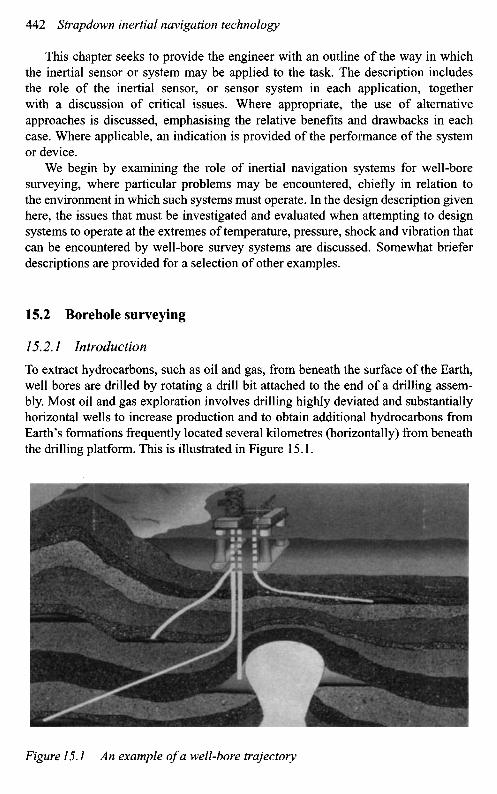
To extract hydrocarbons, such as oil and gas, from beneath the surface of the Earth,well bores are drilled by rotating a drill bit attached to the end of a drilling assem-bly. Most oil and gas exploration involves drilling highly deviated and substantiallyhorizontal wells to increase production and to obtain additional hydrocarbons fromEarth's formations frequently located several kilometres (horizontally) from beneaththe drilling platform. This is illustrated in Figure 15.1.
Figure 15.1 An example of a well-bore trajectory
There is a critical requirement for geological survey, mining and, in the drillingof oil and gas wells, to derive accurate representations of the well-bore trajectory.Such information is vital for:
• cost-effective drilling;• the avoidance of well-bore collisions;• to allow precise relief wells to be drilled should the need arise.
Directional surveys provide definitive data that depicts the position of a boreholeor well path in three-dimensional space. The only point in the path that is trulyknown and in most cases ever likely to be visible (some civil engineering and miningboreholes excluded) is the start point, generally referred to within the oil industry asthe surface position, or the co-ordinates of the well head. The trajectory and positionof the well as it progresses under ground is calculated by taking a series of directionalsurveys, which define the attitude of the well in space at a known measured depthdown the well or along the well path. In its simplest form, the well path is representedby a series of vectors calculated using the survey station point angular data obtainedfrom the survey tool and the incremental depth to each successive survey point. Thefrequency at which surveys are taken and recorded has an impact on the overallaccuracy of the calculated well path from its initial starting point. In general, wellbores with a continuous and/or variable change in attitude (dogleg) require to besurveyed at a higher frequency than a lined out (tangential or straight) hole.
The development and manufacture of measurement systems capable of operatingunderground to the levels of accuracy required presents some major engineeringdesign challenges, not least in terms of the extreme environmental conditions underwhich such systems are required to operate. Well-bore measurement systems may berequired to operate at temperatures in excess of 2000C and at pressures up to 25 000 psi(172 MPa). Whilst well-bore surveys may be carried out following the completion ofthe drilling process, it is economically desirable to generate survey data during thedrilling process, in which case the measurement system must survive and operate ina severe shock and vibrational environment.
Additional factors which impact the design are physical size constraints andlimitations on the levels of electrical power available under the ground. To allowsuch systems to penetrate narrow gauge well bores many thousand of metres beneaththe surface of the Earth, they are required typically to be contained within a diam-eter of a few centimetres, although the length of the equipment is less constrained.Well-bore survey tools are therefore installed in long narrow gauge pressure housings.
15.2.2 Historical background
This section provides a brief history of the various techniques used over the years toprovide well bore trajectory data, culminating in modern magnetic and gyroscopicsystems. There follows a description of a full inertial well-bore survey system inwhich many of the critical design factors are highlighted.
The original instrumentation used within the industry measured hole inclinationonly; this technique indicated the degree to which a drilled well path deviated from

the vertical. Subsequently, a magnet was incorporated into the mechanical plumb bobderivative of this instrument with the assembly allowed to float on jewelled bearingsto provide both attitude with respect to the vertical and the direction of that attitude;to form a compass inclinometer unit. Many units of this type are still in use todayaround the world.
Dual-axis semi-solid-state magnetic sensing tools were first introduced in the late1960s as steering tools, operated on a cable or wire line, primarily to improve theefficient kick-off drilling of deviated directional wells. These wire-line tools pro-vided near continuous data at the surface. Tri-axial/orthogonal magnetic tools weresubsequently introduced and developed to provide survey data during the drilling pro-cess, or measurement whilst drilling (MWD) systems. Such tools have been refinedover the years and, when combined with precise knowledge of the local magneticfield, provide accurate well-bore survey data. The data provided by magnetic surveytools are processed using sophisticated analysis software, which allows down-holesensor problems to be readily identified, so facilitating the potential for real-time datacorrection and uninterrupted operations. Magnetic sensor MWD data have becomeaccepted as definitive quality for several years by the oil industry. However, certainwell geometries preclude the generation of an accurate magnetic survey, when themeasurement system is attempting to operate in the presence of magnetic interference.Under such conditions, gyroscopic survey systems offer an attractive alternative.
It is noted that the use of magnetic sensing tools provides data referenced to mag-netic north. Knowledge of magnetic declination at the well site is therefore requiredand is crucial to allow surveys to be referenced to a geographic/true north referenceframe, as is frequently required. Therefore, precise knowledge of the angle of decli-nation at the survey location is vital to allow a survey to be generated with respect tothe designated reference frame.
Gyroscope sensor survey tools were developed to maintain an establishedgeographic north reference, set at the surface, when the survey tool is underground.In early gyroscopic survey tools, the instrument attitude data generated were timerecorded on photographic film whilst down the hole. The film was read at the surfaceand each survey data set was matched to the appropriate survey depth with the aid of asynchronised surface time log. The three-dimensional co-ordinate position of the wellpath was then calculated, as now, by simple trigonometry. This type of gyroscopictool was used by the oil industry to provide the definitive survey data for most of thedirectional well survey projects in earlier years.
Significant gyroscope developments resulted in the improvement of gyroscopicdata quality. Notably these were the introduction of the first surface record-ing wire-line gyroscopes1 followed by the application of rate-sensing gyroscopes,commonly known as north-seeking gyroscopes, so-called as it describes the systemreferencing technique employed.
1 Surface recording gyroscopic tools, run on wire line in a cased hole, are capable of producing qualitydata in well bores inclined at up to 65° to the vertical. Data quality can become erratic at higher anglesof inclination, where gravitational forces are no longer sufficient to maintain tool transport along the wellpath, and it becomes necessary to pump the survey tool down the well.
Whilst magnetic-survey tools are widely used, systems incorporating high-accuracy gyroscopes with a north-seeking capability are used in regions of highmagnetic interference. This technique is used to derive directional data (azimuth andinclination) as the survey system is lowered or raised in a well-bore. These data,together with hole-depth measurements, are combined using a survey calculationmethod, such as minimum curvature, to yield accurate trajectory information in alocal geographic reference frame.
Modern developments have led to systems built around a full inertial naviga-tion system capability, which make no assumptions about the shape of the well andfacilitate uninterrupted surveys.
The gyroscopic systems currently used to survey underground bore holes aremany and varied. In the following, a system incorporating a full inertial navigationsystem is described, and some of the major factors that influence its design arediscussed.
15.2.3 Inertial survey system
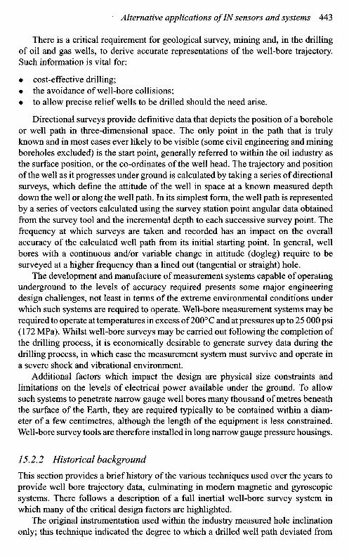
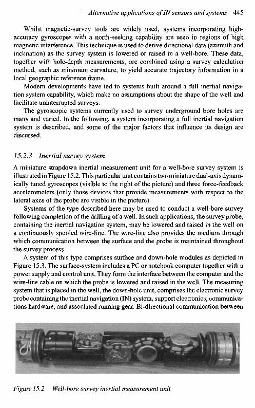
A miniature strapdown inertial measurement unit for a well-bore survey system isillustrated in Figure 15.2. This particular unit contains two miniature dual-axis dynam-ically tuned gyroscopes (visible to the right of the picture) and three force-feedbackaccelerometers (only those devices that provide measurements with respect to thelateral axes of the probe are visible in the picture).
Systems of the type described here may be used to conduct a well-bore surveyfollowing completion of the drilling of a well. In such applications, the survey probe,containing the inertial navigation system, may be lowered and raised in the well ona continuously spooled wire-line. The wire-line also provides the medium throughwhich communication between the surface and the probe is maintained throughoutthe survey process.
A system of this type comprises surface and down-hole modules as depicted inFigure 15.3. The surface-system includes a PC or notebook computer together with apower supply and control unit. They form the interface between the computer and thewire-line cable on which the probe is lowered and raised in the well. The measuringsystem that is placed in the well, the down-hole unit, comprises the electronic surveyprobe containing the inertial navigation (IN) system, support electronics, communica-tions hardware, and associated running gear. Bi-directional communication between
Figure 15.2 Well-bore survey inertial measurement unit
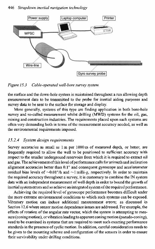
Figure 15.3 Cable-operated well-bore survey system
the surface and the down-hole system is maintained throughout a run allowing depthmeasurement data to be transmitted to the probe for inertial aiding purposes andsurvey data to be sent to the surface for storage and display.
More generally, systems of this type are finding application in both bore-holesurvey and so-called measurement whilst drilling (MWD) systems for the oil, gas,mining and construction industries. The requirements placed upon such systems areoften very demanding both in terms of the measurement accuracy needed, as well asthe environmental requirements imposed.
15.2.4 System design requirements
Survey accuracies as small as 1 m per 1000 m of measured depth, or better, arefrequently required to allow the well to be positioned to sufficient accuracy withrespect to the smaller underground reservoirs from which it is required to extract oiland gas. The achievement of this level of performance calls for azimuth and inclinationalignment accuracies better than 0.1° and consequent gyroscope and accelerometerresidual bias levels of M).01°/h and ~1 milli-g, respectively. In order to maintainthe required accuracy throughout a survey, it is customary to combine the IN systemdata with an independent measurement of well depth in order to bound the growth ofinertial system errors and so achieve an integrated system of the required performance.
Achieving the required level of gyroscope performance becomes difficult underthe more extreme environmental conditions to which such systems can be exposed.Vibratory motion can induce additional measurement errors; as discussed inSection 12.6 where sensor motion dependence issues are addressed. For example, theeffects of rotation of the angular rate vector, which the system is attempting to mea-sure (coning motion), or vibration leading to apparent coning motion (pseudo-coning),need to be examined in systems that are required to meet such exacting performancestandards in the presence of cyclic motion. In addition, careful consideration needs tobe given to the mounting scheme and configuration of the sensors in order to ensuretheir survivability under drilling conditions.
Power supply Laptop computer Printer
WPSC
Wire-line
Gyro survey probe
Such systems may be required to operate at temperatures of 2000C or greater andat pressures up to 25 000 psi (172MPa). In addition, the vibration and shock levelsthat an MWD system must be able to withstand are frequently extreme, whilst theturn rates to which a system may be exposed may be as high as 300 rpm (or 1800°/s).Further design constraints are imposed by the fact that the available power is severelyrestricted in down-hole systems. Last, but not least, the system must fit into a verysmall diameter pressure housing, typically less than 3 or 4 cm internal diameter, tofacilitate its passage through narrow boreholes and/or tubes.
15.2.5 System design issues
Critical factors that have a major influence on the design of such systems aresummarised below:
• survey performance
- typically 1 m per 1000 m of measured hole depth;
• physical size constraints
- diameter ~ few centimetres,
- length constraints - less critical;
• dynamic range of tool motion
- rotation rate up to 300°/s,
- dynamic range up to 108;
• vibration-induced motion whilst running in a bore hole
- qualification level for MWD tools: 2Og RMS (5-500 Hz),
- substantially less for systems operating on wire-line;
• operating temperature range
- zero to 2000C;
• limited power available down hole;• communications limitations between surface and down-hole equipment.
Aspects of the design influenced by these factors are discussed in the followingsections.15.2.5.1 Selection of inertial sensors
The major factors influencing the choice of gyroscopes and accelerometers are theperformance characteristics imposed by the system requirement and physical sizeconstraints. Typically, the diameter into which the inertial sensor block is required tofit within the pressure case is less than 4 cm.
In general, a system that is required to measure position to an accuracy of 1 mper 1000 m of along hole depth, must be capable of aligning in azimuth to anaccuracy of 1 mrad. A gyroscope having a residual bias of 0.01°/h is capable of
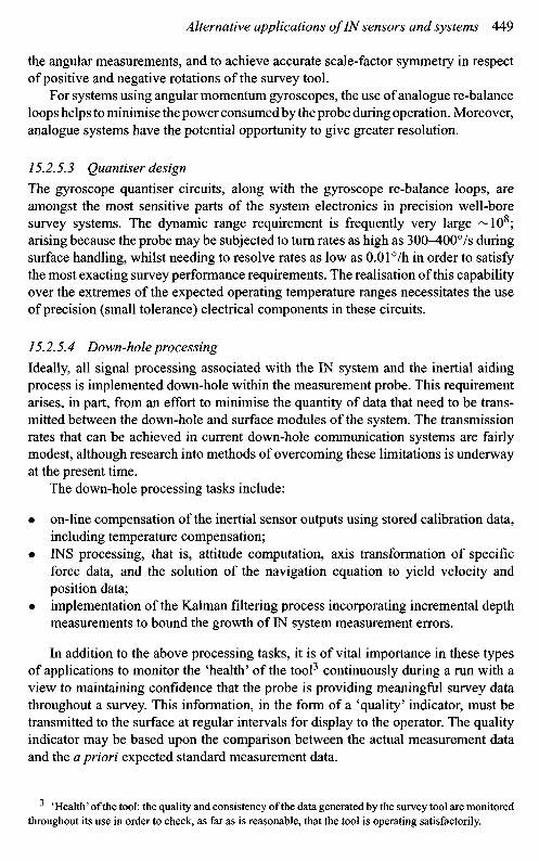
Table 15.1 Gyroscope performance require-ment (post-calibration)
Bias repeatability 0.01 °/hg-Dependent bias 0.010IhJgScale-factor error 100 ppmRandom walk 0.006°/v1iAngular rate limit >200°/s
gyroscope-compassing to this accuracy at Earth latitudes up to 48°. For oil explo-ration and production at higher latitudes, in the north Sea and in Alaska for example,this would suggest the need to use even higher-grade gyroscopes. However, somerelaxation of this performance figure can be accepted in practice, since well paths arenot horizontal over their full length.
Typical gyroscopic sensor performance requirements, which are consideredadequate for the application described here, are given in Table 15.1. The figuresgiven represent the residual errors that can be accepted following system calibration.
There is a range of modern gyroscopic sensors capable of meeting the levels ofperformance defined here; ring laser gyroscopes, fibre optic gyroscopes and conven-tional spinning rotor sensors such as the dynamically tuned gyroscope. However,it is only the latter type which can be accommodated within the limited spaceenvelope. This situation could well change in the not too distant future as a resultof developments in newer technologies; advances in MEMS gyroscope performance,for example, considered in Chapter 7.
Accelerometers with bias repeatability in the region of lOOmicro-g are neededto meet the system performance objectives defined here. Quartz flexure sensors ofthe required size and performance are available, and which are sufficiently ruggedto survive and operate under the environmental conditions to which they will besubjected in this role.
For well-bore survey applications, account must also be taken of the reliabilityand cost of the chosen sensor, as well as the complexity of the sensor or sensor system.For example, in some applications of this type, the inertial sensors may be platformmounted2 to facilitate rotational motion of the sensors [I]. As a consequence of thismotion, a measure of on-line calibration of the inertial sensors can be accomplishedas part of the operational procedure.
15.2.5.2 Sensor re-balance loops
For precision survey systems, the sensor re-balance loops are a critical part of theinertial system electronic support unit. Careful design is necessary to meet systemperformance objectives, particularly to satisfy the requirements for high resolution of
2 A single axis platform is frequently used to give rotational freedom in a direction coincident with thelongitudinal axis of the survey tool.
the angular measurements, and to achieve accurate scale-factor symmetry in respectof positive and negative rotations of the survey tool.
For systems using angular momentum gyroscopes, the use of analogue re-balanceloops helps to minimise the power consumed by the probe during operation. Moreover,analogue systems have the potential opportunity to give greater resolution.
15.2.5.3 Quantiser design
The gyroscope quantiser circuits, along with the gyroscope re-balance loops, areamongst the most sensitive parts of the system electronics in precision well-boresurvey systems. The dynamic range requirement is frequently very large ~108;arising because the probe may be subjected to turn rates as high as 300^-00°/s duringsurface handling, whilst needing to resolve rates as low as 0.01°/h in order to satisfythe most exacting survey performance requirements. The realisation of this capabilityover the extremes of the expected operating temperature ranges necessitates the useof precision (small tolerance) electrical components in these circuits.
15.2.5.4 Down-hole processing
Ideally, all signal processing associated with the IN system and the inertial aidingprocess is implemented down-hole within the measurement probe. This requirementarises, in part, from an effort to minimise the quantity of data that need to be trans-mitted between the down-hole and surface modules of the system. The transmissionrates that can be achieved in current down-hole communication systems are fairlymodest, although research into methods of overcoming these limitations is underwayat the present time.
The down-hole processing tasks include:
• on-line compensation of the inertial sensor outputs using stored calibration data,including temperature compensation;
• INS processing, that is, attitude computation, axis transformation of specificforce data, and the solution of the navigation equation to yield velocity andposition data;
• implementation of the Kalman filtering process incorporating incremental depthmeasurements to bound the growth of IN system measurement errors.
In addition to the above processing tasks, it is of vital importance in these typesof applications to monitor the 'health' of the tool3 continuously during a run with aview to maintaining confidence that the probe is providing meaningful survey datathroughout a survey. This information, in the form of a 'quality' indicator, must betransmitted to the surface at regular intervals for display to the operator. The qualityindicator may be based upon the comparison between the actual measurement dataand the a priori expected standard measurement data.
3 'Health' of the tool: the quality and consistency of the data generated by the survey tool are monitoredthroughout its use in order to check, as far as is reasonable, that the tool is operating satisfactorily.
15.2.5.5 Compensation for vibration-induced errors
The inertial sensors will be subject to significant levels of shock and vibration whilstoperating in the down-hole environment. In order that the system can be capable ofsurviving and operating under such conditions, careful attention must be given tothe mounting of the sensors and electronics in the down-hole assembly. The design ofsuitable shock/anti-vibration mounts is a critical part of the design of such systems,and one, which occupies much of the designer's attention when developing systemsfor this role.
Whilst the vibration environment is clearly most severe when attempting to surveyduring the drilling process (MWD operations), significant levels of oscillatory motioncan also arise in cable operated systems depending on how the sensors are supportedin the well. For example, pseudo-coning motion may be present as a result of thegyroscope's sensitivity to cyclic angular motion; see Section 12.6.2.
For a dual-axis gyroscope subject to cyclic motion about a single input axis,a pseudo-coning rectification error is induced having a time-invariant component(Aco) given by the following equation:
-AQ1
where Q is the amplitude of applied cyclic angular rate, H is the angular momentumof gyroscope rotor and A is the moment of inertia of gyroscope rotor about input axis.
An angular acceleration correction term may be calculated as a function of thesegyroscopic parameters enabling a software correction to be applied.
15.2.5.6 Thermal design issues
Critical to the achievement of the required inertial sensor measurement accuracyis the temperature compensation of the output signals from each gyroscope andaccelerometer. To this end, it is often necessary to install temperature sensors on,or as close as possible to, each inertial sensor. The resulting measurements, com-bined with temperature coefficient data stored in the probe, facilitate the on-linetemperature compensation of the inertial measurements throughout a survey. Thecalibration process by which the temperature coefficient data are obtained is outlinedlater.
In order to achieve the required temperature operating range using inertial sen-sors with limited temperature capability, it is common practice in such applicationsto run the survey probe within a heat shield coupled to a heat sink. Depending on thecapacity of the heat sink, this approach can allow extended operating times at hightemperature.
15.2.5.7 Power requirements and management
In the development of systems for a well-bore surveying application, it is vital to min-imise the power consumed by the down-hole system and to avoid excessive transientpower demands. This is necessary because of down-hole power limitations, as wellas a desire to avoid excessive heat generation in the down-hole equipment. Hence,highly efficient systems and techniques are vital, moreover, to cope with the power
surge needed to run up the gyroscopes; the gyroscopes may be run up sequentiallyfollowing tool switch-on. As mentioned earlier, analogue re-balance loops may beused to minimise the power needed to operate the gyroscopes in the high-accuracyclosed-loop mode.
15.2.5.8 IN system aiding techniques
An IN system provides very good short-term accuracy, but its uncompensated long-term performance does not fulfil the survey precision needs of the oil, gas, andconstruction industries, where run times varying from many hours to weeks may berequired. Therefore, for each application, aiding techniques combined with statisticalfiltering methods are required to bound, or restrict the growth of, the time-dependentinertial sensor errors.
For systems operating underground, the options for IN system aiding are some-what limited. One possible method for aiding a probe-mounted IN system involvesstopping the probe periodically during its descent/ascent in the borehole. Whilst theprobe is stationary, any components of velocity indicated by the IN system are clearlyattributable to IN system errors and can be used to update that system. The Kalmanfiltering process implemented in such applications is often referred to as 'zero veloc-ity updating'. As described in Chapter 13, this technique may be used for correctingthe IN system velocity estimates; additionally estimates of attitude errors and instru-ment biases, which propagate as velocity errors within the IN system, may also begenerated. The technique allows the appropriate corrections to be applied as part ofthe filtering process.
This method of aiding is a natural choice for systems designed to generate surveydata as part of the bore-hole drilling process; the MWD systems referred to earlier.During the construction of a well, drilling ceases from time to time to allow additionaldrill pipe(s) to be added before a further section of well can be constructed. At thistime, it can usually be assumed that the survey probe is stationary. Through the sameprocess, it is possible to obtain improved estimates of gyroscopic errors and so updatethe gyroscope calibration process during system operation.
Under dynamic conditions, a measurement of tool motion along the well boreis required; that is, a measurement of position or velocity along the path of thewell bore. Whilst there are various methods of generating this information [2],a commonly used technique is to measure the incremental changes in distance movedalong the well. For wire-line or cable operated survey systems, proprietary depthmeasurement systems are available to provide this information. Precision systems ofthis type allow corrections for cable temperature and tension to be applied as partof the depth measurement process. Knowledge that the IN system cannot move out-side the confines of the well bore is implicit within the Kalman filter measurementprocesses adopted in such applications.
15.2.6 System calibration and test
Vital to the successful operation of any IN system are the calibration processesundertaken during manufacture, and, subsequently, carried out on-site prior to runningthe survey tool. An on-site calibration is required in order to check for any unexpected
changes in inertial sensor performance prior to the start of the survey process, andto remove any switch-on to switch-on bias variation. This procedure helps to ensurethat the best possible performance is extracted from the inertial sensors during thesubsequent survey operation.
Detailed calibration and characterisation is carried out following manufacture,using a calibration and test procedure. This process involves a series of multi-positional and rate-transfer tests in order to characterise the system in terms of fixedbiases, ^-dependent biases, scale-factor linearity, mounting misalignment, and cross-coupling errors. The probe is installed in a temperature chamber whilst on the teststand. This arrangement allows data to be collected as the probe is cycled over thespecified operational temperature range. As part of this process, it is often neces-sary to consider the direction of any temperature change in order to take account oftemperature hysteresis effects.
In order to extract the best possible performance from the gyroscopes, a furtherprocess of calibration may be implemented on-site prior to each run. The objective ofthe on-site calibration is to estimate and compensate for switch-on to switch-on biasvariations. This procedure takes the form of a multi-positional test with the probenominally horizontal. Similar techniques are described in Chapter 8, in relation tothe laboratory testing of inertial sensors and systems. These tests are a vital step inthe process for qualifying the performance of the system to ensure that the sensorsand the system are suitable as well as being optimised for this survey role.
All survey tools undergo extensive calibration, laboratory testing and environ-mental qualification prior to operation in the field. Further testing of developmenttools may be carried out using van trials and other surface testing (funicular railwaytests for example) to emulate, as accurately as possible, the movement of a tool in anunderground well.
In-hole testing is carried out in known test wells, which have been surveyedmany times in the past, for which the well path is believed to be reasonably welldefined. However, as mentioned at the start of this section, the only point in the wellpath that is truly known is the surface position, or the co-ordinates of the well head.This being the case, well tests involving surveys conducted whilst both descendingand ascending in the well (usually referred to as in-run and out-run surveys) areundertaken, any shift in the measured position on returning to the surface, withrespect to the true surface location, providing a good indicator of survey systemperformance. Additional tests are carried out to check for survey repeatability overa number of repeat runs, consistent results giving further confidence that the surveytool is operating satisfactorily.
15.2.7 Concluding remarks
Robust and reliable survey systems based on inertial sensor technology can beproduced, and a number of sophisticated techniques have been developed to ensurethat accurate and reliable operation can be achieved in a hostile environment.
It is the combination of careful calibration and characterisation of the INsystem during manufacture, on-site calibration, and the on-going aiding process
implemented during operations that are key features for the successful operationof a precision down-hole system. This process is designed to yield the best pos-sible system performance, whilst constantly checking for errors throughout surveyoperations; errors which may render the survey of insufficient quality, or invalid.
Continuing research developments in this field are directed towards the designof gyroscope based survey tools capable of delivering precision survey data whilstdrilling (measurement whilst drilling systems). The ultimate aim is to produce direc-tional steering tools, which control the path of a well-bore directly throughout thedrilling process.
15.3 Ship's inertial navigation systems (SINS)
One of the most demanding applications of inertial systems for achieving very highaccuracy is the navigation of naval ships and submarines, which may be required tooperate covertly for long periods of time in any part of the ocean, including the polarregions. Early work in the United Kingdom at the Admiralty Compass Observatory(ACO), Slough (formerly part of the Defence Evaluation and Research Agency),led to the development of very stable platform systems: these devices provided anautonomous navigation capability in the 1 nautical mile per day class, incorporatinggyroscopes with residual biases of less than 0.001 °/h. The single-axis rate-integratinggyros used for these applications were highly sophisticated instruments with gasbearings, which needed to operate in a closely controlled temperature environmentto achieve the level of performance required for highly accurate navigation.
A British programme to develop a ship's inertial navigation system at the ACOdates from the mid-1950s. The initial system design incorporated rate-integratinggyroscopes developed by the Charles Stark Draper Laboratory in the United States,where the rotor was supported by high-precision ball bearings. This project ledto laboratory tests and initial sea trials in 1961. The system became fully opera-tional in 1968. During this time, ACO played a major part in the development ofa new rate-integrating gyroscope for SINS in which the rotor was supported bya gas bearing, which resulted in an order of magnitude improvement in perfor-mance. SINS Mk. 1 was a completely analogue design, sensitive to temperatureand power supply variations and had significant limitations when operating at highlatitudes. Its successor, SINS Mk. 2 featured gyroscope pulse torquing, integratedcircuits and digital computation and resulted in production equipment with full polarcapability in 1976.
The early systems provided very accurate IN performance, but were both largeand expensive to manufacture and maintain, in fact the system was so massive that itrequired a special access hatch to get it into and out of a ship; clearly this limited thenumber of ship classes that could accommodate this class of technology. A number ofefforts were undertaken to devise a smaller but equally accurate device, but this did notprogress significantly until the 1980s. The process of developing a smaller, lighterand less costly replacement system, with potential application in a broader rangeof ships, began in 1983, initially as the ship's low cost inertial navigation system
(SLINS) development, and subsequently as an international collaborative ventureculminating in NATO SINS [3]. This is a strapdown system based upon ring lasergyroscope technology.
15.3.1 NATOSINS
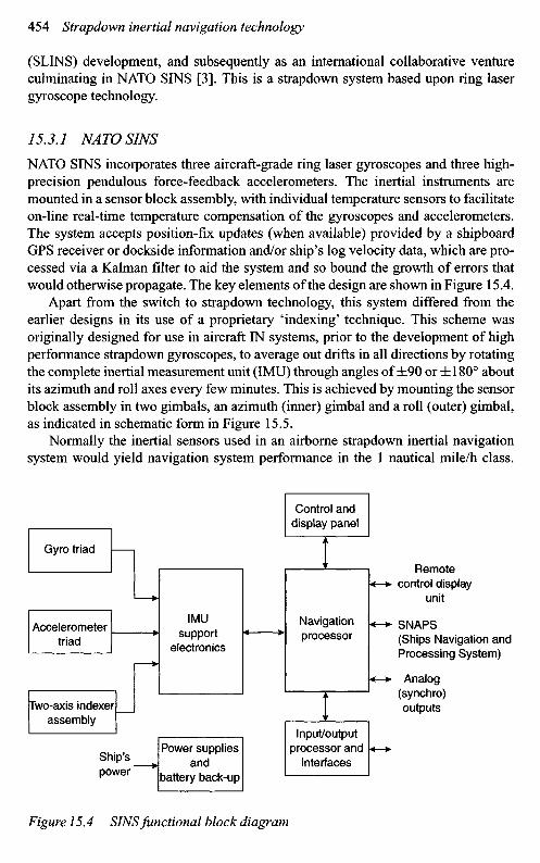
NATO SINS incorporates three aircraft-grade ring laser gyroscopes and three high-precision pendulous force-feedback accelerometers. The inertial instruments aremounted in a sensor block assembly, with individual temperature sensors to facilitateon-line real-time temperature compensation of the gyroscopes and accelerometers.The system accepts position-fix updates (when available) provided by a shipboardGPS receiver or dockside information and/or ship's log velocity data, which are pro-cessed via a Kalman filter to aid the system and so bound the growth of errors thatwould otherwise propagate. The key elements of the design are shown in Figure 15.4.
Apart from the switch to strapdown technology, this system differed from theearlier designs in its use of a proprietary 'indexing' technique. This scheme wasoriginally designed for use in aircraft IN systems, prior to the development of highperformance strapdown gyroscopes, to average out drifts in all directions by rotatingthe complete inertial measurement unit (IMU) through angles of ±90 or ±180° aboutits azimuth and roll axes every few minutes. This is achieved by mounting the sensorblock assembly in two gimbals, an azimuth (inner) gimbal and a roll (outer) gimbal,as indicated in schematic form in Figure 15.5.
Normally the inertial sensors used in an airborne strapdown inertial navigationsystem would yield navigation system performance in the 1 nautical mile/h class.
Figure 15.4 SINS functional block diagram
Gyro triad
Control anddisplay panel
Accelerometertriad
IMUsupport
electronics
Navigationprocessor
Remotecontrol display
unit
SNAPS(Ships Navigation andProcessing System)
Analog(synchro)outputsTwo-axis indexer
assembly
Ship'spower
Power suppliesand
battery back-up
Input/outputprocessor and
interfaces
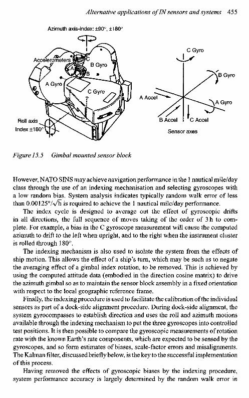
Figure 15.5 Gimbal mounted sensor block
However, NATO SINS may achieve navigation performance in the 1 nautical mile/dayclass through the use of an indexing mechanisation and selecting gyroscopes witha low random bias. System analysis indicates typically random walk error of lessthan 0.00125%/h is required to achieve the 1 nautical mile/day performance.
The index cycle is designed to average out the effect of gyroscopic driftsin all directions, the full sequence of moves taking of the order of 3 h to com-plete. For example, a bias in the C gyroscope measurement will cause the computedazimuth to drift to the left when upright, and to the right when the instrument clusteris rolled through 180°.
The indexing mechanism is also used to isolate the system from the effects ofship motion. This allows the effect of a ship's turn, which may be such as to negatethe averaging effect of a gimbal index rotation, to be removed. This is achieved byusing the computed attitude data (embodied in the direction cosine matrix) to drivethe azimuth gimbal so as to maintain the sensor block assembly in a fixed orientationwith respect to the local geographic reference frame.
Finally, the indexing procedure is used to facilitate the calibration of the individualsensors as part of a dock-side alignment procedure. During dock-side alignment, thesystem gyrocompasses to establish direction and uses the roll and azimuth motionsavailable through the indexing mechanism to put the three gyroscopes into controlledtest positions. It is then possible to compare the gyroscopic measurements of rotationrate with the known Earth's rate components, which are expected to be sensed by thegyroscopes, and so form estimates of biases, scale-factor errors and misalignments.The Kalman filter, discussed briefly below, is the key to the successful implementationof this process.
Having removed the effects of gyroscopic biases by the indexing procedure,system performance accuracy is largely determined by the random walk error in
Azimuth axis-index: ±90°, ±180°
AccelerometersB Gyro
A GyroC Gyro
Roll axis
Index ±180°
A Accel
C Gyro
B Gyro
A Gyro
B Accel C Accel
Sensor axes
the gyroscopes; this is the principal error that remains, and unfortunately cannotbe removed through indexing as it is not a systematic error process.
The major functions of the Kalman filter in NATO SINS are as follows:
• to monitor system parameters, gyroscope and accelerometer biases, scale-factorerrors and misalignments, measured during dock-side calibration;
• to carry out system resets at sea, based upon navigational updates, the amount bywhich the system is reset being controlled by the accuracy of the fix;
• to control ship's log damping, by removing the log input when the discrepancybetween log and system exceeds a pre-set value in either north or east directions.
The Kalman filter forms estimates of the errors in position, velocity and attitude,as well as inertial sensor biases, scale-factor errors and misalignments. On receipt ofa position (latitude/longitude) fix, this information is compared with the latitude andlongitude estimates generated by the inertial system, the differences forming inputs tothe Kalman filtering process. Tests are applied to assess the 'credibility' of the externalfix data, and manual intervention by the operator is allowed to review and assess thedata prior to validating the fix before it is applied to the filter. Following acceptanceof the fix, the Kalman estimates of system error states are used to 'reset' the system.
Successful implementation of an inertial navigation system that compensates forthe inherent errors in inertial sensors has provided ships with precision navigationdata anywhere in the world; with positional accuracy ~ 1 nm/day error. The systemdemonstrated that systematic errors could be compensated leading to greater per-formance, whilst offering major reductions in size, weight and both acquisition andlife cycle costs.
15.4 Vehicle stabilisation and control
This section examines some current applications in which inertial sensors andsystems are used to maintain control of land, sea and airborne vehicles duringnormal operations and throughout manoeuvres. These range from autopilots to safetysystem, as well as fault diagnostic approaches.
15.4.1 Autopilots
Autopilots have a number of functions, as discussed below, but the fundamentalobjective of an autopilot is to modify the intrinsic natural behaviour of a vehicle toproduce the desired response characteristic. This involves making the behaviour of thevehicle more predictable and less influenced by external disturbances and variationsin component characteristics. Moreover, the ideal design aim is to make the responseof the vehicle constant over its entire operating envelope. This section will considertwo common applications; autopilots in guided weapons and in aircraft.
An autopilot is a closed loop system used to stabilise the chosen or demandedflight path of a vehicle. In the case of an aircraft or missile it maintains a responseand track that is reasonably resistant to external disturbances, but is still responsiveto control demands.
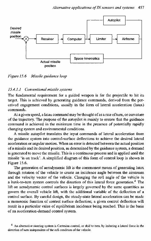
Figure 15.6 Missile guidance loop
15.4.1.1 Conventional missile systems
The fundamental requirement for a guided weapon is for the projectile to hit itstarget. This is achieved by generating guidance commands, derived from the per-ceived engagement conditions, usually in the form of lateral acceleration (latax)commands.
At a given speed, a latax command may be thought of as a rate of turn, or curvatureof the trajectory. The purpose of the autopilot is mainly to ensure that the guidancecommand is achieved in the minimum time in the presence of potentially rapidlychanging system and environmental conditions.
A missile autopilot translates the input commands of lateral acceleration fromthe guidance system into control-surface deflections to achieve the desired lateralacceleration or angular motion. When an error is detected between the actual positionof a missile and its desired position, as determined by the guidance system, a demandis generated to move the missile. This is a continuous process and is applied until themissile 'is on track'. A simplified diagram of this form of control loop is shown inFigure 15.6.
The generation of aerodynamic lift is the commonest means of generating lataxthrough rotation of the vehicle to create an incidence angle between the airstreamand the velocity vector of the vehicle. Changing the roll angle of the vehicle ina bank-to-turn system controls the direction of this lateral force generation.4 Thelift on aerodynamic control surfaces is largely governed by the same quantities asgovern the overall vehicle lift, with the additional variable of the deflection of acontrol surface. By careful design, the steady-state lateral acceleration can be madea monotonic function of control surface deflection; a given control deflection willresult in a particular value of equilibrium incidence being reached. This is the basisof an acceleration-demand control system.
4 An alternative steering system is Cartesian control, or skid to turn, by inducing a lateral force in thedirection of turn independent of the roll condition of the vehicle.
Desiredmissileposition
Receiver Computer Limiter Airframe
Autopilot
Space kinematicsActual missile
position
The aerodynamic design of a missile is a compromise between stability, whichdetermines the response time to an input demand, and the available control power.Control power dictates the maximum steady state latax that may be achieved.However, if both rapid response and high latax are required, they will not beachievable through aerodynamic design alone.
Even when a reasonable aerodynamic compromise between the equilibriumcharacteristics of static stability and maximum trim incidence is achieved, the result-ing dynamic response may not necessarily be satisfactory. Missile configurationstypically have poor aerodynamic damping, which unless augmented with rollerons(see Section 15.4.2), results in an undesirable oscillation about the trim condition.Motion about the trim condition is known as the weathercock mode, after the ten-dency of a weathercock (or weather vane) to align itself with the wind direction.In some missile designs, the guidance command is passed through a notch filter toavoid excitation of this mode, but internal filters do not prevent its excitation byexternal disturbances, such as wind gusts.
A missile may gain details of a target's motion, with respect to a given referenceframe, from the output generated by a seeker, or from a command receiver collectinginformation from external systems. This information is processed by a computer togenerate the lateral force commands required to manoeuvre the missile, and thenapplied by the autopilot. The use of a limiter is important to ensure that the appliedmanoeuvre demands do not destroy the missile, either by generating forces beyondits structural capability or by causing it to reach an angle-of-attack (incidence angle)that causes the missile to become unstable. A range of instruments may be used tomonitor these effects and, in combination with the autopilot, ensure that missile hasa wide operational envelope; this is the form of the system required to achieve thefundamental goal of an autopilot.
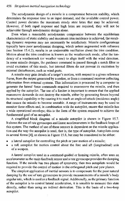
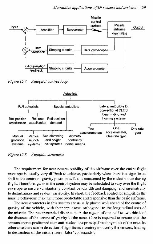
A simplified block diagram of a missile autopilot is shown in Figure 15.7.It shows the use of rate gyroscopes and linear accelerometers in the feedback loops ofthis system. The method of use of these sensors is dependent on the missile applica-tion and the way the autopilot is used, that is, the type of autopilot. Autopilots comein several forms [4], as shown in Figure 15.8, but may be considered to be either:
• a lateral autopilot for controlling the pitch or yaw motion of a missile;• a roll autopilot for motion control about the fore and aft (longitudinal) axis
of a weapon.
A lateral autopilot used in a command-guided or homing missile, often uses anaccelerometer as the main feedback sensor and a rate gyroscope provides the dampingfunction. If the missile has two planes of symmetry, then two autopilots would berequired to provide the control of motion in the orthogonal pitch and yaw planes.
The simplest application of inertial sensors is to compensate for the poor naturaldamping by the use of rate gyroscopes to provide measurements of a missile's bodyangular rate, which is used as a feedback signal. Additionally, as the primary functionof the autopilot is to control lateral acceleration, it is sensible to measure this statedirectly, rather than using an indirect derivation. This is the basis of a two-loopautopilot.
Amplifier
Ratefeedback
Accelerationfeedback
Servomotor
Missilecontrolsurface Missile
airframekinematics
Shaping circuits Rate gyroscope
Shaping circuits Accelerometer
Output
Figure 15.7 A utopilot control loop
The requirement for near neutral stability of the airframe over the entire flightenvelope is usually very difficult to achieve, particularly when there is a significantshift in the centre of gravity position as fuel is consumed by the rocket motor duringflight. Therefore, gains in the control system may be scheduled to vary over the flightenvelope to ensure substantially constant bandwidth and damping, and insensitivityto disturbances and system variability. In short, the feedback controller simplifies themissile behaviour, making it more predictable and responsive than the basic airframe.
The accelerometers in this system are usually placed well ahead of the centre ofgravity of the vehicle, with their input axes orthogonal to the longitudinal axis ofthe missile. The recommended distance is in the region of one half to two thirds ofthe distance of the centre of gravity to the nose. Care is required to ensure that thesensors are not positioned at an anti-node of the principal bending mode of the missile;otherwise there can be detection of significant vibratory motion by the sensors, leadingto destruction of the missile from 'false' commands'.
Input
Autopilots
Roll autopilots Special autopilots Lateral autopilots forconventional CLOS,
beam riding andhoming systemsRoll position
stabilisationRoll rate
stabilisationRoll position
demand
Twoaccelerometers
Oneaccelerometer,One rate gyro
One rategyro
Manualguidancesystems
Verticallaunch
systems
Sea-skimmingand height
lock systems
Azimuthcontrol by
inertial means
The favoured position for the rate gyroscopes is at an anti-node5 where the angularmotion, owing to vibratory motion is a minimum, although this is not the optimumposition from the overall design point of view. The input axes of the rate sensorsare arranged to sense pitch and yaw motion, so they are orthogonal to the missile'slongitudinal axis. Consequently, the sensors' output signals are proportional to thepitch and yaw rates. The accuracy of the sensor, such as its drift rate, is not animportant requirement for the performance of the gyroscopes, as they are only requiredto provide a measurement of angular rate, particularly with low-noise characteristics.Similarly, the accelerometers are not required to give measurements to high accuracywith great stability over long periods for this function.
The closed loop, self-correcting behaviour characteristic of the guidance loopreduces the inertial instrument performance requirements compared with those oftypical inertial navigation applications. Hence, the inertial sensors in an IMU usedin a navigation system may be used to provide the 'feedback' data for the autopilot,provided the inertial sensors are appropriately positioned and have suitable bandwidthresponses. This is developed further in the following section.
15.4.1.2 Vertical launch missile systems
During the launch phase, of this class of weapon, guidance information may not beavailable and inertial measurements must be used to define the missile state vector.In such circumstances, the guidance commands are generated from inertial measure-ments. For example, during the initial launch manoeuvre from a vertical canister, orsilo, the missile state has to be determined from inertial measurements, with a desiredend state programmed into the missile's control system during the launch sequence.Initially, the speed is low and less impulse is required to achieve a given headingchange than later in flight. Unfortunately, the available aerodynamic lift is also low,so the lateral acceleration autopilot designs described earlier are unlikely to provecapable of exploiting this phenomenon.
During the launch phase, the greatest force acting on a vertically launched missileis typically the boost-motor thrust, and this must be rotated with respect to the velocityvector to generate the required lateral acceleration. Rotating the missile body requiresa means of applying moments. As the available aerodynamic moments are also small,provision is typically made to deflect the motor efflux laterally in order to applycontrolling moments to the body of the missile and consequently steer the missile.In this phase of flight, maximum lateral acceleration is achieved when the thrust actsperpendicular to the trajectory, that is, with the missile apparently flying sideways!
It is usual to use an attitude-control autopilot during this phase of flight by using avelocity-vector steering technique. The autopilot loop is closed by setting the deflec-tion of the motor's jet to be proportional to the difference between the actual angularbody rate, again measured by the angular rate sensors in the IMU, and the demandedbody-rate command.
^ In a rigid missile, gyroscope and accelerometers are placed at a node and this has very little adverseimpact on the performance of the gyroscopes.
If there are no constraints on the apogee height, then a simple attitude autopi-lot may be adequate. However, in some circumstances the open-loop control ofthe trajectory inherent in attitude control is unlikely to be effective, so someform of closed-loop control of the trajectory is required, such as velocity-vectorcontrol.
As part of its normal operation, the IMU will produce an estimate of the missilevelocity vector with respect to the chosen inertial reference frame. The control systemwill generate a velocity direction demand. The objective of the steering loop is togenerate a command signal to be fed into an attitude loop of the form describedearlier. In this case the proper function of the attitude loop is to produce a lateralacceleration demand, which is proportional to the velocity error, in order to reducethat error to zero
15.4.1.3 Aircraft
Commercial and military aircraft have made significant advances in their operationalcharacteristics over the last few decades, particularly with respect to operationalrange and control complexity. Furthermore, the development of IN technology hashad a number of significant impacts on aircraft operations, for example the successfuldevelopment of the IN system has made the traditional role of the navigator redundant.Development of fly-by-wire techniques and advanced avionics systems has madeaircraft far more agile. As a consequence there has been an increase in the difficultyin manual control of some combat aircraft, particularly those with so-called negativestability, where the centre-of-gravity is ahead of the centre-of-lift, giving a negativestatic margin.
Automatic control equipment has been developed to minimise pilot fatigue andreduce the more tedious aspects of flying, so that the pilot can concentrate on themajor operational decisions. The so-called automatic pilot's function is to stabilisethe flight path by maintaining the aircraft at a constant height and in the commandeddirection during cruise phases of flight. During manoeuvres to a new altitude orbearing, the autopilot generates the commands to ensure the transition is smooth andleads to a stable flight path. There are some differences between the missile andaircraft autopilots as aircraft use a combination of roll motion and yaw deflections toturn, in a so-called 'bank-to-turn' manoeuvre. In contrast, most tactical missiles useCartesian control in a 'skid-to-turn' type of manoeuvre.
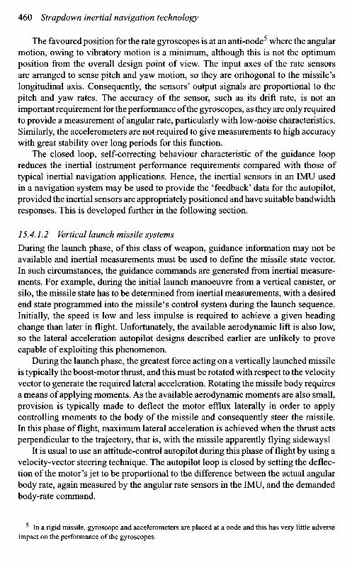
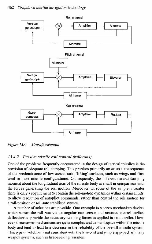
Gyroscopes are at the heart of this type of autopilot used in 'cruise control',as shown in Figure 15.9. In this case the various channels of the autopilot are shown.The pitch channel gyroscopic sensors detect motion of the aircraft about its horizontalor pitch axis and provide command signals to the elevator control surfaces in the tailplane to counter the sensed motion. This channel can also respond to signals generatedby a pre-set altimeter, such as a barometric device or a radar-based sensor, to ensurethe designated altitude is maintained.
The yaw and roll channels respond to motion sensed by the appropriate gyro-scopic sensors, in a simplified system the yaw channel motion may be sensed bya gyro-stabilised magnetic compass.
Roll channel
Pitch channel
Altimeter
Yaw channel
Figure 15.9 A ircraft autopilot
15.4.2 Passive missile roll control (rollerons)
One of the problems frequently encountered in the design of tactical missiles is theprovision of adequate roll damping. This problem primarily arises as a consequenceof the predominance of low-aspect-ratio 'lifting' surfaces, such as wings and fins,used in most missile configurations. Consequently, the inherent natural dampingmoment about the longitudinal axis of the missile body is small in comparison withthe forces generating the roll motion. Moreover, in some of the simpler missilesthere is only a requirement to contain the roll-motion dynamics within certain limits,to allow resolution of autopilot commands, rather than control the roll motion fora roll-position or roll-rate stabilised system.
A number of solutions are possible. One example is a servo-mechanism device,which senses the roll rate via an angular rate sensor and actuates control-surfacedeflections to provide the necessary damping forces as applied in an autopilot. How-ever, these servo-mechanisms are quite complex and demand space within the missilebody and tend to lead to a decrease in the reliability of the overall missile system.This type of solution is not consistent with the low-cost and simple approach of manyweapon systems, such as heat-seeking missiles.
Verticalgyroscope
Amplifier Ailerons
Airframe
Verticalgyroscope
Amplifier Elevator
Airframe
Gyro-compass
Amplifier Rudder
Airframe
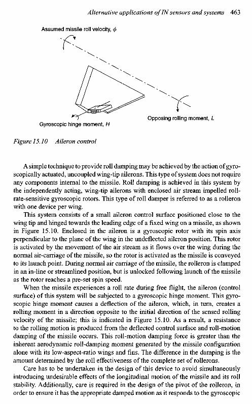
Figure 15.10 Aileron control
A simple technique to provide roll damping may be achieved by the action of gyro-scopically actuated, uncoupled wing-tip ailerons. This type of system does not requireany components internal to the missile. Roll damping is achieved in this system bythe independently acting, wing-tip ailerons with enclosed air stream impelled roll-rate-sensitive gyroscopic rotors. This type of roll damper is referred to as a rolleronwith one device per wing.
This system consists of a small aileron control surface positioned close to thewing tip and hinged towards the leading edge of a fixed wing on a missile, as shownin Figure 15.10. Enclosed in the aileron is a gyroscopic rotor with its spin axisperpendicular to the plane of the wing in the undefleeted aileron position. This rotoris activated by the movement of the air stream as it flows over the wing during thenormal air-carriage of the missile, so the rotor is activated as the missile is conveyedto its launch point. During normal air carriage of the missile, the rolleron is clampedin an in-line or streamlined position, but is unlocked following launch of the missileas the rotor reaches a pre-set spin speed.
When the missile experiences a roll rate during free flight, the aileron (controlsurface) of this system will be subjected to a gyroscopic hinge moment. This gyro-scopic hinge moment causes a deflection of the aileron, which, in turn, creates arolling moment in a direction opposite to the initial direction of the sensed rollingvelocity of the missile; this is indicated in Figure 15.10. As a result, a resistanceto the rolling motion is produced from the deflected control surface and roll-motiondamping of the missile occurs. This roll-motion damping force is greater than theinherent aerodynamic roll-damping moment generated by the missile configurationalone with its low-aspect-ratio wings and fins. The difference in the damping is theamount determined by the roll effectiveness of the complete set of rollerons.
Care has to be undertaken in the design of this device to avoid simultaneouslyintroducing undesirable effects of the longitudinal motion of the missile and its rollstability. Additionally, care is required in the design of the pivot of the rolleron, inorder to ensure it has the appropriate damped motion as it responds to the gyroscopic
Assumed missile roll velocity,
Gyroscopic hinge moment, HOpposing rolling moment, L
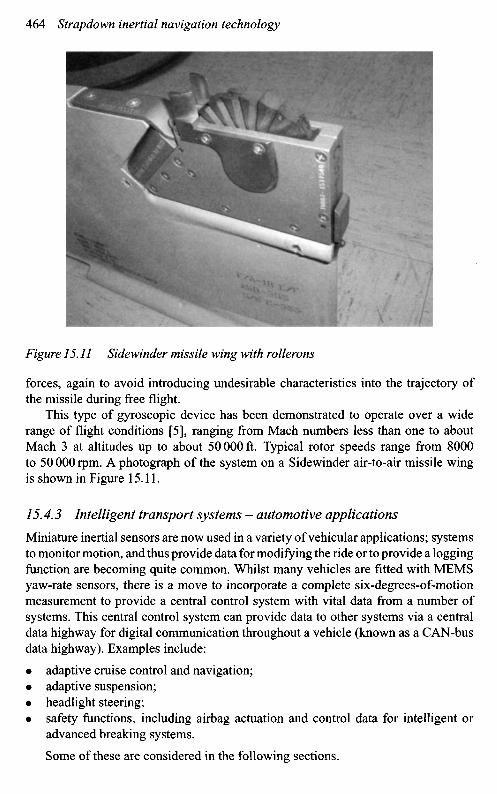
Figure 15.11 Sidewinder missile wing with rollerons
forces, again to avoid introducing undesirable characteristics into the trajectory ofthe missile during free flight.
This type of gyroscopic device has been demonstrated to operate over a widerange of flight conditions [5], ranging from Mach numbers less than one to aboutMach 3 at altitudes up to about 50000 ft. Typical rotor speeds range from 8000to 50000rpm. A photograph of the system on a Sidewinder air-to-air missile wingis shown in Figure 15.11.
15.4.3 Intelligent transport systems - automotive applications
Miniature inertial sensors are now used in a variety of vehicular applications; systemsto monitor motion, and thus provide data for modifying the ride or to provide a loggingfunction are becoming quite common. Whilst many vehicles are fitted with MEMSyaw-rate sensors, there is a move to incorporate a complete six-degrees-of-motionmeasurement to provide a central control system with vital data from a number ofsystems. This central control system can provide data to other systems via a centraldata highway for digital communication throughout a vehicle (known as a CAN-busdata highway). Examples include:
• adaptive cruise control and navigation;• adaptive suspension;• headlight steering;• safety functions, including airbag actuation and control data for intelligent or
advanced breaking systems.
Some of these are considered in the following sections.
This class of application demands low-cost sensors, such as MEMS devices.In general, the cost and the reliability are the key aspects of the demanding specifi-cation, as relatively low-performance rate sensors are adequate for the vast majorityof these applications.
15.4.3.1 Navigation
The navigation systems used in vehicles are based broadly on satellite navigationtechniques, such as GPS [6], but use of information from inertial navigation sensorsmay augment the accuracy of this basic system. The major limitation of the externalreference system is the possible loss of signal from one, or more, of the satellites,which can occur for a number of reasons; common examples include:
• obscuration by terrain or foliage;• obscuration by cultural objects in the landscape, such as tunnels, mountains or
buildings.
During these periods of loss of satellite navigation signals, the inertial navigationsystem fills in the gaps, particularly if the loss of satellite data is intermittent; hencethe inertial system acts in a similar fashion to a flywheel in an engine. Provided thedatabase of the area being travelled is accurate, then the road system may be consid-ered as a set of urban canyons (defined by the stored database), so the errors may bebounded and used in Kalman filters to compensate for many of the systematic errors.
In simpler car navigation systems, linking of the output from the odometer(or a speedometer and a clock) to an electronic map is an adequate reversionarymode for intermittent loss of the 'GPS' signal. The true value of a more sophisticatedsystem is to limit the growth of navigation errors during the loss of the 'GPS' naviga-tion data and thus help the receiver re-acquire the 'GPS' signal following a prolongedloss of signal.
It is important to distinguish between position and location: a positioning ornavigation system will supply co-ordinates, but a location system requires a map.Car navigation systems usually have the ability to take an address and transform thisinto a co-ordinate set from a stored map and provide the driver with instructions onhow to reach the destination. Map-matching techniques may be used in the simplersystems; in this case it is assumed that the car will be on a road, usually close to theGPS co-ordinates transposed on to a digital map. A good map-matching algorithmrelies on maps with a high positional accuracy, usually of the order of 30 m, to avoidincorrect road selection. Dead reckoning techniques, described in Section 2.1, arealso used to determine absolute position of the vehicle.
Owing to the short duration navigation requirements and the aiding techniquesthat are available, the requirements on the inertial sensor are modest. This is an idealapplication for a low-cost MEMS device.
15.4.3.2 Suspension and braking systems
Active suspension or adaptive chassis systems [7] use either electrical or hydraulicactuation to stiffen the suspension of the vehicle and thereby control the dynamical
motion of a vehicle. This means better stability as a vehicle turns a corner by con-trolling the roll motion of a vehicle. The other feature of this type of system concernsthe pitching motion of the vehicle, either smoothing out the oscillations as it travelsalong a bumpy road, or preventing the front of a vehicle from dipping under heavybraking action, thus ensuring the rear tyres maintain maximum adhesion to the road.
An intelligent braking system aims to provide an enhancement to the alreadywidely used anti-skid braking system (ABS). In the case of an intelligent brakingsystem, a single-axis accelerometer and gyroscope are mounted on the vehicle andare required to measure the yaw rate and lateral acceleration of the vehicle. Thecontrol system aims to keep an even distribution of the vehicle's mass by adjustingthe damping of the shock absorbers in the suspension system.
A more sophisticated system may embody an electronic throttle control, a steeringwheel position indicator, wheel speed sensors and a modified braking system. Thevehicle's system 'knows' the safe turning radius or speed for a given wheel speedand steering wheel movement from stored data. If the inertial sensors detect motionbeyond the designated safe parameters for a given speed, then the control systemremoves power and applies a suitable braking force independently to each wheel.
These techniques may be combined with an autopilot for navigation and guidanceof robotic vehicles. These vehicles may then undertake hazardous activities such asmine clearance, cleaning up contaminated waste products or spraying pesticides.
15.4.3.3 Car monitoring
One research effort with cars involves precision location systems that act in a similarrole to an aircraft's 'black box' accident recording system. This system would deter-mine the attitude and position of a vehicle, that is, its trajectory on a road or withrespect to any other suitable reference.
In this case, an integrated navigation system with a tuned Kalman filter is used.The inertial navigation system provides the attitude, position and turn rates of thevehicle at a high data rate. A 'GPS' receiver will provide position fixes every second.The data may be combined in a Kalman filter to provide highly accurate informationabout the speed, position and attitude of a vehicle over a given period immediatelybefore an accident. The current projection is that such an integrated navigation systemcould provide position to an accuracy of about 5 cm!
Clearly, this is a direct application of a low-cost integrated inertial navigationsystem.
15.4.3.4 Safety
Other automotive safety projects are concerned with collision avoidance and preven-tion of vehicles wandering off roads unintentionally. Such object-sensing functionsmay be implemented using radar or electro-optical systems. Again, the completesafety system would involve an integrated inertial navigation system and a suitablestored-map database.
MEMS accelerometer sensors are used for activation of the explosive train in anairbag passenger protection system.
15.4.4 Intelligent transport systems - trains
Gyroscopes are used on modern high-speed locomotives and carriages to control thetilting as they travel at high speed around tight bends. This enables existing railwaylines to be used safely by trains travelling at a higher speed than the designed safeoperating speed for a conventional train.
Another use of inertial sensors that is the subject of on-going research involvesthe use of an inertial measurement unit on a locomotive or carriage to record themotion characteristics of 'the ride' throughout its travels. Periodic detailed analysisof the recorded data could be used for a range of analysis such as:
• condition of locomotive and carriage wheels, particularly the occurrence of 'flatspots';
• performance of the suspension;• riding quality of the track.
15.4.5 Personal transport
One of the most common applications of inertial principles in transport is the use of thegyroscopic effect to keep a balance and control of any two-wheeled machine, such asa bicycle or a motor cycle. The angular momentum of the wheels provides the forcerequired to keep the rider vertical when travelling in a straight line. Steering maybe accomplished by moving the handlebars so that an orthogonal torque is createdto move the rider in the desired direction. Alternatively, the rider may lean to one sideto create a force out of the vertical plane, creating a turning moment and consequentlydisturbing the equilibrium for travel in a straight line.
However, more recently there have been significant developments in 'two-wheel'transportation, as described in the following section.
15.4.5.1 Segway and Ibot (human transporter)
A recent development in this aspect of transport is the Segway machine, invented byDean Kamen, which has a stabilised platform where the rider stands. The applicationof gyroscopic techniques enables the rider to balance safely on two wheels positionedon either side of the machine, which may be driven backwards or forwards by an elec-trical motor. A smart wheel chair, known as the Ibot, has also been invented using thesame principles of a stabilised platform to allow it to operate or balance on two wheels.
The application of this technology to a wheel chair makes it far more versatilethan the conventional device. The self-balancing feature means that the wheel chairmay be used safely on two wheels, (wheelie mode), which may be exploited to:
• make the wheel chair stand up on its rear wheels to lift the occupant to the samelevel as other people in a standing group;
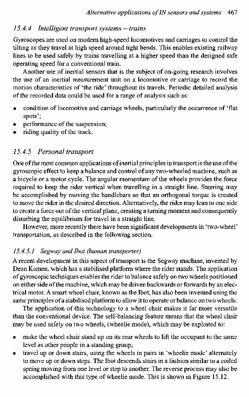
• travel up or down stairs, using the wheels in pairs in 'wheelie mode' alternatelyto move up or down steps. The Ibot descends stairs in a fashion similar to a coiledspring moving from one level or step to another. The reverse process may also beaccomplished with this type of wheelie mode. This is shown in Figure 15.12.
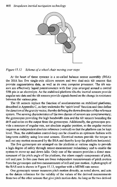
Figure 15.12 Scheme of a wheel chair moving over steps
At the heart of these systems is a so-called balance sensor assembly (BSA):the BSA has five single-axis silicon sensors and two dual-axis tilt sensors thatprovide augmentation data, as well as its own computer processor. The tilt sen-sors are effectively liquid potentiometers with four pins arranged around a centralfifth pin in an electrolyte. As the stabilised platform tilts the inertial sensors provideangular rate data and the tilt sensors provide signals based on the change in resistancebetween the various pins.
The tilt sensors replace the function of accelerometers on stabilised platforms,described in Appendix C, as they undertake the 'spirit level' function and thus definethe direction of the gravity vector, thereby defining the down direction of the referencesystem. The sensing characteristics of the two classes of sensors are complementary;the gyroscopes providing the high bandwidth data and the tilt sensors bounding thedrift and noise on the output from the gyroscopes. Additionally, the gyroscopes pro-vide a measure of angular rate, not absolute angular position, so the angular motionrequires an independent absolute reference (vertical) so that the platform can be keptlevel. Thus, the stabilisation control-loop can be closed in an optimum fashion withlong-term stability using low-cost sensors. Electrical motors provide the torque tonull out any motion measured by the BSA and thereby keep the platform horizontal.
The five gyroscopes are arranged on the platform at various angles to providea high degree of safety through sensor-measurement redundancy and to enable thesystem to move up and down hills. Only one of the sensors provides a direct mea-surement of the pitch angle of the platform, the others supply components of pitch,roll and yaw. In this case there are three independent measurements of pitch motionfrom the gyroscopes and two measurements of roll and yaw motion. A photograph ofthe BAS unit is shown in Figure 15.13, together with a MEMS rate sensor.
One gyroscopic sensor measures pitch motion directly, as noted above, and actsas the datum reference for the validity of the values of the derived measurementsfrom two of the other sensors that give pitch motion data. As long as the two derived
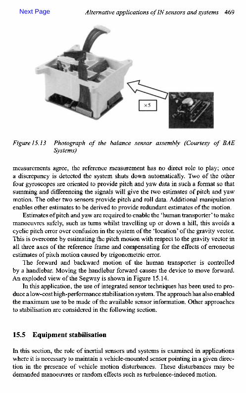
Figure 15.13 Photograph of the balance sensor assembly (Courtesy of BAESystems)
measurements agree, the reference measurement has no direct role to play; oncea discrepancy is detected the system shuts down automatically. Two of the otherfour gyroscopes are oriented to provide pitch and yaw data in such a format so thatsumming and differencing the signals will give the two estimates of pitch and yawmotion. The other two sensors provide pitch and roll data. Additional manipulationenables other estimates to be derived to provide redundant estimates of the motion.
Estimates of pitch and yaw are required to enable the 'human transporter' to makemanoeuvres safely, such as turns whilst travelling up or down a hill, this avoids acyclic pitch error over confusion in the system of the 'location' of the gravity vector.This is overcome by estimating the pitch motion with respect to the gravity vector inall three axes of the reference frame and compensating for the effects of erroneousestimates of pitch motion caused by trigonometric error.
The forward and backward motion of the human transporter is controlledby a handlebar. Moving the handlebar forward causes the device to move forward.An exploded view of the Segway is shown in Figure 15.14.
In this application, the use of integrated sensor techniques has been used to pro-duce a low-cost high-performance stabilisation system. The approach has also enabledthe maximum use to be made of the available sensor information. Other approachesto stabilisation are considered in the following section.
15.5 Equipment stabilisation
In this section, the role of inertial sensors and systems is examined in applicationswhere it is necessary to maintain a vehicle-mounted sensor pointing in a given direc-tion in the presence of vehicle motion disturbances. These disturbances may bedemanded manoeuvres or random effects such as turbulence-induced motion.
Next Page