alternative designs of a superconducting synchronous...
TRANSCRIPT

Proceedings of the 2008 International Conference on Electrical Machines Paper ID 1485
1
Alternative designs of a superconducting synchronous generator: the Southampton approach
Kevin F. Goddard, Bartosz Lukasik and Jan K. Sykulski, Senior Member IEEE
School of Electronics and Computer Science, University of Southampton, Southampton SO17 1BJ, United Kingdom Tel: +44 (0)23 8059 5352 / 2496 / 3448, Fax: +44 (0)23 8059 3709
[email protected], [email protected], [email protected]
Abstract-The paper describes various designs undertaken at the University of Southampton for building both cored and coreless superconducting synchronous generators using high temperature superconducting (HTS) tapes. An overview of electromagnetic and mechanical design issues is presented and scalability is considered. Results are included for the full (original) size machine and extended to a double size unit.
I. INTRODUCTION
The constant improvements in performance of high-temperature superconducting (HTS) materials open new application possibilities. HTS conductors with critical current densities as high as 200A/mm2 at zero magnetic field are now available. A practical superconducting winding can easily cross the barrier of 60A/mm2 – and for some of the designs presented in this paper reached 66A/mm2 – whereas in conventional water cooled windings it is not realistic to use current densities in excess of 10A/mm2. The prospect of using such high current densities to greatly increase the output power of the machine, and simultaneously reduce the losses, is very appealing [1][2]. However, as explained in Section IV, the mechanical properties of the HTS material make it too difficult to build a HTS stator winding. In the machines considered here, superconducting coils are used only in the rotor winding.
The characteristics of HTS materials also impose additional requirements that complicate the rotor design. The structural materials must be suitable for use at the low temperatures required by the superconductor. One of the most difficult issues that needs to be addressed for cryogenic designs is the difference in thermal contraction coefficients between various components. The danger is that different contraction coefficients may cause high thermal stresses. To overcome these problems it may be necessary to design the structure to be more flexible, but this makes it more difficult to ensure that it is strong enough to carry the loads imposed by centrifugal forces. The other important issue that has to be resolved is the method of limiting the heat leak into the cryostat. The structure that supports the cold rotor needs to be constructed in a way that minimizes the heat leak while at the same time providing enough stiffness to keep the critical speeds out of the operating range and being able to transfer torque to the drive shaft. Extra space is also required for thermal insulation in the air gap.
The real advantages of a superconducting rotor are achieved only with a large enough machine to benefit from the reduction in losses and gain in current density despite the cost of cooling and the space occupied by thermal insulation.
II. PROPERTIES OF HIGH-TEMPERATURE SUPERCONDUCTING MATERIALS
Since HTS materials are ceramic, they are much less tolerant to bending than conventional metallic conductors. HTS conductors usually take the form of a thin tape that includes a metallic matrix or substrate. This provides mechanical support to the superconducting material, bridges any micro-cracks, and provides an alternative current path in the event that superconductivity is lost. Such designs place restrictions on the shape of the coils that can be produced: flat coils are not too difficult to wind but almost any other shape would be impractical.
HTS coils can work at current densities that would make cooling virtually impossible should a conventional metal conductor be used. However, it is important to recognize that an HTS coil is not equivalent to a conventional coil with a very low resistance. The E–J characteristics are highly non-linear and depend greatly on the temperature and on the strength and orientation of the magnetic field. The resistance rises rapidly with increases in temperature, current, and magnetic field with the component normal to the face of the tape having a much greater effect than the other components.
While reducing the temperature of the superconductor enables it to tolerate higher current densities and higher flux densities, it also increases the cost of cooling. Moreover, since liquid nitrogen and liquid air have good heat-transfer characteristics, their use enables the cooling system to be more efficient, but requires the working temperature to be restricted so that the cooling fluid does not freeze.
Although it is expected that it should soon be possible to obtain YBCO coated conductors in lengths and ratings suitable for the manufacture of electrical machines [3], this is still not the case and for our current designs BiSCCO conductors were selected. Although BiSCCO superconductors can achieve high current densities, their tolerance to magnetic fields is poor. Consequently, to obtain the high current densities that are required to justify the use of a superconducting winding, the magnetic field component normal to the face of the tape must
978-1-4244-1736-0/08/$25.00 ©2008 IEEE

Proceedings of the 2008 International Conference on Electrical Machines
2
be restricted to a relatively low value (≈0.25 T). Since the high current density in the coil can easily generate such a field, this is not easy. As noted above, it is not practical to twist the tape to align with the field; hence we must align the field with the tape, which requires the use of iron.
III. CHOICE OF OTHER MATERIALS
While in principle there are a very large number of materials that could be used to construct the rotor, in reality the choice is quite restricted; most materials were rejected either because they are expensive, or difficult to obtain, or because of lack of relevant data to have confidence that they have suitable low-temperature properties.
The only magnetic materials seriously considered for use at cryogenic temperatures were Invar and 9% Ni steel. The 9% Ni steel offers a higher saturation flux density and a higher thermal expansion coefficient that is a better match to the other materials considered. However, since it is not certified for use at temperatures below 73 K, it can not be considered for use at such lower temperatures where its structural performance is critical. In addition, although it would be cheaper in large quantities, it is much more difficult to obtain when only a small amount is needed.
The choice of non-magnetic structural materials is, in principle, quite wide. However, we have chosen to rely on two main materials: stainless steel and G10 fibreglass. These materials are widely used in cryogenic applications, and there exists considerable experience in using them; alternative materials were considered only if they offered some clear advantage over each of the above. One of such materials was Aluminium, which was used for the outer vacuum wall of the coreless rotor, where it also serves as an eddy-current screen to protect the rest of the rotor from the high-frequency fields that are driven by space harmonics of the stator MMF.
IV. STATOR
The ceramic nature of all currently available high temperature superconductors restricts the shape of a coil that can be wound from HTS conductors, making the prospect of building a HTS stator winding impractical. Most common configurations require the conductors to be bent and twisted with very small radii, which would greatly reduce the critical current of the conductor. It would be difficult but possible to build the stator winding out of flat coils, but such a winding would be unlikely to make good use of space. Thus much of the benefit of high current densities would be lost.
Other issues that would have to be addressed if the construction of a superconducting stator were to be attempted include appropriate field shaping around the coils as well as the AC losses in the superconductor.
The DI-BiSCCO tape is very sensitive to the magnetic field component perpendicular to the broad face of the tape and this unwelcome property requires the field to be controlled. In all the rotor designs considered here, as well as in an earlier transformer project [4], the field is guided by the use of iron to redirect much of the flux around the coils. It should be noted,
however, that it would not be practical to apply such flux diverters to the stator winding. It would be difficult to find a shape that would make them effective and probably even harder to produce such a shape. The choice of the material is also a challenge. For example the powdered iron composite used in [4] would not be effective at high flux densities, while solid iron rings would have high eddy-current losses that would not be acceptable in the cryostat. Even solid iron flux diverters would probably saturate if the air-gap flux density were increased above 1T.
It is also worth observing that an YBCO superconductor has much lower dependence of the critical current on the magnetic field, hence flux diverters might not be required.
In addition to the effect on the critical current, the normal component of magnetic flux density can drive large eddy currents and thus may produce high AC losses. To avoid excessive losses, the superconductor must have sufficient spare current carrying capacity to screen itself from the normal field component. But it must be remembered that even then eddy current losses would still be induced in the metallic matrix of the HTS tape.
In order to reduce the cost and avoid the need to design a new stator, an existing stator is used. This was taken from a 100kVA, 2-pole induction machine, of bore diameter 330mm and iron length 325mm. A short-pitched (14/24) conventional 2-layer winding with 3-turn coils is distributed in 48 slots and connected in a parallel star arrangement.
V. CORED ROTOR DESIGN
The use of a magnetic rotor core greatly reduces the required rotor MMF and makes it easier to control the magnetic field in the rotor winding. This allows the rotor winding to be constructed with much less superconducting tape and to operate at a higher temperature.
The rotor core (Fig. 1) is formed from a stack of 9%Ni steel plates that are held together by 9%Ni steel bolts and dowels [5]. While this material could become brittle at very low temperatures (below the operating range), it was nevertheless considered the best choice as the thermal contraction is a reasonably good match to the coils and their stainless steel formers, thus ensuring that they do not shrink onto the pole necks. Moreover, the good magnetic characteristics allow more
Fig.1. A cross-section of the superconducting machine with a cored rotor (left) and the 3D view (right)
Proceedings of the 2008 International Conference on Electrical Machines
3
space to be allocated to superconducting coils and help reduce the flux density in these coils; as a result the coils can give satisfactory performance at slightly higher temperatures.
A. Problems with Flood Cooling It was originally intended that the cored design would be
flood cooled. However, at the time, we could not find a satisfactory design for the mechanical connections between the rotor core and the rotating liquid vessel. The 9% Ni steel used for the rotor core has a lower thermal expansion coefficient than the stainless steel proposed for the liquid vessel. To accommodate the resulting differential thermal contraction would require the structure to be flexible. Unfortunately this structure must also withstand the high liquid pressure generated by centrifugal forces. While it cannot be proven conclusively that no satisfactory shape exists, it is clear that any solution that used these materials would be bulky. If the cylindrical wall of the liquid vessel were made from a G10 fiberglass tube, the thermal stress would be low. However, there is a risk that the connections to the ends of this tube would leak. In view of all these difficulties, it was decided that flood cooling would not be used. Instead the liquid cryogen was restricted to a few pipes with copper links employed to conduct heat into these pipes (Fig. 2).
In the course of the current project, an alternative method of connecting the inner rotor assembly to the liquid vessel was identified, which might overcome this problem; this is elaborated on in Section VI.B.
B. Supporting the Cold Rotor The two ends of the cold rotor assembly are each supported
by a conical array of G10 fibreglass beams that provide the required stiffness without conducting too much heat into the cold part of the machine (Fig. 3). The material was chosen because it has a high ratio of stiffness to thermal conductivity. One such assembly connects the cold rotor to the enclosing vacuum vessel, while the other is connected to a separate inner shaft that can slide axially to accommodate contraction of the cold rotor relative to the warm vacuum vessel.
VI. CORELESS ROTOR DESIGN
The main advantage of the coreless rotor design is a significant reduction in mass of the rotor. The second project, currently undertaken at Southampton University, aims to build such a generator [6]. Although the superconducting material is superior to the one used previously (as it was purchased more recently and benefits from the continuing advances in material processing), it still imposes similar limitations on the values of perpendicular and parallel magnetic fields at which the HTS tape can deliver its best performance. One solution is that flux diverters continue to be used as in the cored design.
Removing the core introduces a set of new challenges in relation to supporting and assembling the machine, since there is no longer a rigid structure in the centre. To address these problems, a number of configurations were considered as described below. Regrettably though, none of the coreless designs considered could achieve high air-gap flux densities; although this would be possible, even with the superconducting tape used, if a larger machine were built.
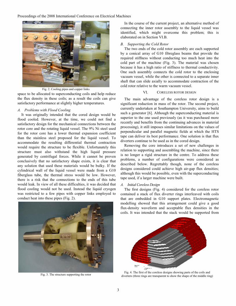
A. Initial Coreless Design The first designs (Fig. 4) considered for the coreless rotor
contained a stack of flux diverter rings interleaved with coils that are embedded in G10 support plates. Electromagnetic modelling showed that this arrangement could give a good flux-density waveform and acceptable flux densities in the coils. It was intended that the stack would be supported from
Fig. 4. The first of the coreless designs showing parts of the coils and
diverters (three rings are transparent to show the shape of the middle ring)
Fig. 3. The structure supporting the rotor
Fig. 2. Cooling pipes and copper links

Proceedings of the 2008 International Conference on Electrical Machines
4
the outside by hoop stress in the wall of the liquid vessel, using two packing pieces to transfer the load. These would be made from the two halves of a G10 tube, with groves machined into the inner cylindrical face to locate the rings and coils. However, although the design looked attractive, significant problems were soon encountered as explained below.
Since the coefficient of thermal expansion normal to the layers of the G10 composite is much higher than that of the metal retaining tube, it would be difficult to prevent the coil formers becoming loose as the rotor is cooled down to its working temperature. Even without the thermal contraction problems, manufacturing tolerances would make it virtually impossible to prevent the coils from being loose without making them tight. If they were tight they would tend to push the rings away from their outer supports, making it hard to transmit the acceleration torque to the outer support structure. To overcome these problems, it would be necessary to place some type of springs between each coil former and one of the adjacent rings, but there is not enough space to put springs in these locations. It might be possible to make the rings and the coils themselves to act as springs, but this would considerably increase the risk of coils getting damaged – thus lowering the reliability of the whole construction – which might have prevented the completion of the project.
Since the flux diverters and coil subassemblies are thin (about 6 mm), centrifugal forces would impose large deflections on these components if they were to be supported from their outer edges alone. Consequently, their deflections would be limited by additional contact forces near the inner edges of the rings. This might appear to solve the problem by preventing large deflections and the associated stresses, but – when manufacturing tolerances are considered – it becomes clear that the balance of the rotor could change in an unpredictable manner as the speed and temperature of the cold rotor assembly are varied. Due to the large number of contact surfaces involved in supporting some of the rings, a large number of manufacturing tolerances contribute to this uncertainty.
Although there is plenty of space for cooling fluid in the centre of the rotor, it is not easy to guide this fluid in and out of this space. Slots or holes would have to be machined into some
of the rings at their ends. Before the liquid is allowed to flow back through the central space, the cold fluid would have to be piped around the sides of the rotor to the far end. The pipes would have to be placed between the two packing pieces, which would make it more difficult to centre the middle coil or ring.
Having considered all these difficulties we could not assure the reliability of the final assembly. This, combined with the difficulty of machining the two packing pieces, lead us to abandon this particular design.
B. Alternative Coreless Design To overcome the problems described above, we next
considered using through bolts to hold the stack together (Fig. 5). As before, the external shape of the stack is approximately cylindrical. This maximizes the area of the coils and the air-gap flux density, which also has a reasonably good waveform, thus magnetically this would be a good solution. However, it proved exceedingly difficult to produce a satisfactory mechanical design.
As in the previous design, each coil would be placed on a fibreglass former extending across the central part of the machine, which allows the coils and rings to be centred by the through bolts. The use of through bolts makes the pole pieces critical structural components. It was therefore decided that they must be made from Invar. Unfortunately, this greatly increases the difficulty of adsorbing the differential thermal contraction. While finite-element modelling suggested that excessive stresses in the through bolts could be avoided by careful adjustment of clearances, this was not considered a satisfactory solution, since it would impose very tight manufacturing tolerances.
Another problem arises from differential contraction between the pole pieces and the enclosing liquid vessel. This is the same problem that led to the rejection of flood cooling in the cored rotor. As previously explained, it would not be practical to make the ends of the liquid vessel sufficiently flexible to adsorb the thermal contraction while retaining sufficient strength to contain the liquid at the high pressures generated by centrifugal forces.
In the course of the current project, a possible solution to this problem was identified. In this arrangement, the ends of the liquid vessel are closed by relatively thick metal plates that can easily withstand the liquid pressure. The required flexibility is provided by a separate G10 plate that is attached to the liquid vessel near to the axis of rotation, and to the inner rotor assembly at substantially greater radii. While this design would overcome the conflict between strength and flexibility, there are other requirements that need to be satisfied. In particular, the connection must reliably centre the inner rotor so that the balance of the rotor does not alter too much with repeated cooling cycles, and must do so with a high stiffness so that it does not reduce the critical speeds significantly. Calculations have shown that sufficient stiffness can be obtained, but full analysis to determine the reliability of the centering has not been undertaken.
Fig. 5. Coreless design with the through bolts

Proceedings of the 2008 International Conference on Electrical Machines
5
The entire cold part would be supported within the vacuum vessel by a similar structure to that described in Section V B.
While it might be possible to produce a satisfactory mechanical design, there was insufficient confidence to justify further work.
C. Final Coreless Design In this design all the coils are of the same size and are
mounted on a thin walled tube in the middle of the rotor (Fig. 6). With this arrangement the perpendicular component of the magnetic field of a coil is largely counteracted by the magnetic field produced by nearby coils. It is therefore possible to remove the 9% Nickel plates from between the coils. Unfortunately, by removing the flux diverters, the coils are no longer shielded from the stator winding field and therefore the current in each coil has to be reduced to ensure low E fields in the superconductor. However, retaining the pole pieces decreases the undesirable effect of increased perpendicular field in the last few coils and allows for some shaping of the air gap flux density waveform, which still is worse than that in the previous coreless designs. Due to a lower current and smaller coil area the air gap flux density is also decreased.
In order to minimise the cold mass that must be supported with minimum heat leak, the pole pieces are warm and placed outside the cryostat (Fig. 6b). Unfortunately, displacing the pole pieces away from the rotor winding causes the perpendicular magnetic field in the last few coils to increase; it was therefore necessary to replace the flux diverters at the top and bottom of the winding. In this design only the coils and the two flux diverters are enclosed in the stainless steal vessel flooded with liquid nitrogen for cooling. It is believed that this arrangement poses the least amount of assembly problems.
Despite somewhat inferior electromagnetic performance, the significant advantages in lower mass, simpler assembly, higher reliability, easier and cheaper manufacturing of the coils (as they are all identical) and overall simplicity have proven deciding factors in selecting this design over the ones discussed earlier. It should not be taken for granted, however, that one of the suggested alternatives would not offer a competitive solution – should an answer to the mechanical and thermal problems highlighted be found.
VII. SCALABILITY OF THE PROPOSED DESIGN
Both the cored machine already built and the coreless version which has been designed and will soon be constructed
at the University of Southampton are too small for the use of superconductors to be directly beneficial. Thus the possibility of scaling the designs was addressed and a set of models with the machine size doubled was built and analysed. Fig. 7 shows the designs which were chosen for this investigation. The first design has a salient core and each of the coils has its own flux diverter. The final double size configuration has 20 coils. The second model has been built with 32 coils arranged to follow the curvature of the stainless steel vessel in which the rotor is enclosed. In the last design the coils are no longer shielded from the armature fields and must therefore work at a lower current; hence a larger number of coils is required. The double size arrangement required 70 coils in the rotor.
The analysis was conducted with the assumption that the interest lies in building the machine cooled by liquid nitrogen or liquid air, therefore the temperatures at which the scalability of the designs is estimated are 70K and 66K using sub-cooled liquid nitrogen and 60K with sub-cooled liquid air.
In order to better predict the critical current, the parallel (B||) and perpendicular (B┴) components of the magnetic flux density within each coil are combined into one in the form of an equivalent magnetic flux density parameter. By scaling down the value of the parallel component of the field by a certain factor (depending on the superconducting tape used) it is possible to approximate the critical current density by a function of the magnitude of the resulting vector. The simple interpolation function enables the critical current to be estimated for any values of B|| and B┴. The equivalent flux density is assumed to be
2||2'⎟⎟
⎠
⎞
⎜⎜
⎝
⎛+= ⊥
fsB
BB (1)
where B||, B┴ are the relevant components of the magnetic flux density and sf is a scaling factor.
Manufacturer’s characteristics of the HTS tape allow establishing the scale factor and the equivalent flux density dependence on the critical current for a given temperature. By using 2D FE models it is possible to find the dependence of the equivalent flux density on the current and number of turns in the coils. By equating the critical current of the tape to the current in the coils the maximum current can be estimated.
The combined graphs showing the maximum current as a function of the number of turns, as well as the resulting air-gap flux density, at the temperature of 66K, are shown in Fig. 8.
Fig. 6. The two most recent designs of the coreless rotor
Fig. 7. Three scaled up designs analysed

Proceedings of the 2008 International Conference on Electrical Machines
6
The graphs show that the best electromagnetic performance is obtained by the cored design with 80 turn coils carrying 140A and producing an air-gap flux density exceeding 1T. This may be a slightly overestimated value since the results come from a no-load 2D model and do not account for the end effects and the effects of applying load. Nevertheless, they show a high possible gain if the machine of this design is scaled. Unfortunately it can also be seen that the curve tends to flatten. The achievable air-gap flux density rises from 0.975T at 70K to 1.01T at 60K, which confirms that saturation is the limiting factor.
Saturation is less important in the case of the second analysed design and from the graph it can be seen that the performance of the machine can be improved further by increasing the number of turns in the coils. In this case, the difficulty lies in controlling the magnetic field in the top-most coils. The diverters and the tips of the pole piece tend to saturate because they are in the region where the perpendicular component of the magnetic field driven by the coils is highest. The flux is attracted to the stator core and that contributes to the perpendicular component of the field in the top-most coils. This design allows achieving air-gap flux densities of nearly 0.55T at 66K and gains a lot by cooling it further down to achieve the flux densities above 0.67T at 60K.
The other coreless design shows remarkable scalability possibilities, provided of course that the high cost of the superconducting material is acceptable. The penalty for adopting this design is a non optimal use of the superconducting tape. The good news is that at 66K and with 80 turn coils it is possible to achieve flux density of 0.75T in the air-gap and by cooling the superconductor further to 60K it is possible to achieve nearly 1T. But the cost of using a 200A rated HTS tape at 83A current might not be economically viable.
Electric loading of the machine depends on the stator design and so does not depend on the rotor design. The graph presented in Fig. 7 allows estimating the possible magnetic
loading for any of the configurations within the range considered. When the values predicted by the simulations of a double size machine are compared with the performance of the smaller size machine models they show that for the cored design the magnetic loading can be improved while for the coreless designs saturation of the flux diverters becomes more of a problem; only the one without flux diverters shows substantial benefit from scaling.
VIII. CONCLUSIONS
Using high temperature superconducting (HTS) tapes for the rotor winding of a synchronous generator offers significant advantages in terms of improved efficiency and/or reduced size but presents unique challenges. The design is a compromise between electromagnetic performance, mechanical and thermal considerations and reliability requirements. Controlling magnetic flux distribution in the region of the winding is of crucial importance to achieve high current densities in BiSCCO tapes, while the choice of construction and support materials (magnetic and non-magnetic) to operate at low temperatures remains difficult. Both cored and coreless designs have been explored and found to be possible. A cored rotor was built and tested, while several scenarios have been considered for the coreless version and one is being pursued. The demonstrator is expected to be completed early 2009.
ACKNOWLEDGMENT
This work is sponsored by the EPSRC (UK), grant number EP/D000688/1.
REFERENCES [1] P.N. Barnes, M.D. Sumption, and G.L. Rhoads, “Review of high power
density superconducting generators: Present state and prospects for incorporating YBCO windings,” Cryogenics, 45, (10-11), pp. 670-686, 2005.
[2] S.S. Kalsi, K. Weeber, H. Takesue, C. Lewis, H.W. Neumueller, and R.D. Blaugher, “Development status of rotating machines employing superconducting field windings,” Proceedings of the IEEE, 92(10), pp. 1688-704, 2004.
[3] A.P. Malozemoff, S. Fleshler, M. Rupich, C. Thieme, X. Li, W. Zhang, A. Otto, J. Maguire, D. Folts, J. Yuan, H-P. Kraemer, W. Schmidt, M. Wohlfart and H-W. Neumueller, “Progress in high temperature superconductor coated conductors and their applications,” Supercond. Sci. Technol., 21, No 3, 2008.
[4] J.K. Sykulski, K.F. Goddard, and R.L. Stoll, “High temperature superconducting demonstrator transformer: design considerations and first test results,” IEEE Transactions on Magnetics, 35, (5). pp. 3559-61, 1999.
[5] M.K. Al-Mosawi, C. Beduz, and Y. Yang, “Construction of a 100kVA High Temperature Super-conducting synchronous generator,” IEEE Transactions on Applied Superconductivity, vol. 15, pp. 2182-2185, 2005.
[6] M.K. Al-Mosawi, K. Goddard, C. Beduz, and Y. Yang, “Coreless HTS synchronous generator operating at liquid nitrogen temperatures,” IEEE Transactions on Applied Superconductivity, vol. 17, pp. 1599-1602, 2007.
Fig. 8. Current and air-gap flux density as functions of the number of turns for various designs at 66K