alternative transmission media for third ... transmission media for third-generationinterface...
TRANSCRIPT

NTIA Report 83-121
Alternative Transmission Media forThird-Generation Interface Standards
J.A. HullA.G. Hanson
L.R. Bloom
u.s. DEPARTMENT OF C:OMMERCEMalcom Baldrige, Secretary
Susan G. Stuebing, Acting Assistant Secretaryfor Communications an(j Information
May 1983


PREFACE
This report is submitted as partial completion of a study
being conducted for the National Communications System, Washington,
DC, under Reimbursable Order Number RD 2-40167. The monitoring of
this project is performed by the National Communications Sy'stem
Office of Technology and Standards, headed by Mr. Marshall L. Cain,
with administrative monitoring by Mr. Dennis Bodson, of that
office.
; ; ;

TABLE OF CONTENTS
Page
LIST OF FIGURES. • • • • • • • • • • • • • • • • • • • • • • • • • 'I vii
LIST OF TABLES . • • • • • • • • • • • • • • • • • • • • • • • II vii
LIST OF ACRONYMS AND ABBREVIATIONS • • • • • • • • • • • • • • • • II viii
LIST OF SYMBOLS. • • • • • • • • • • • • • • • • • • • • • • • • • II ix
1
1
3
3
5
5
11
12
12
13
13
13
14
15
16
17
19
22
23
25
26
29
29
31
Analytical Description. • • • • .
Fm Based on Impulse Response ••••••
Fm Based on Response to a Step Function •
Fm Based on Measured Attenuation.
3.1.1
3.1.2
3.1.3
3.1.4
PROPERTIES AND LIMITATIONS OF OPTICAL FIBER WAVEGUIDES.
3.2 Cable Evaluation ••
3.3 Twisted Wire Pairs ••
4.1 Optical Fiber Waveguide Parameters
4.2 Analytical Description •.•••••
4.
3 •
2.
ABSTRACT • • • •
1 . INTRODUCTION.
1.1 Purpose•••••••
1.2 Scope. • • ••••
1.3 Organization of Report. • •••••••
1.4 Background. • ••••••••
NEW DTE/DCE STANDARDS AND THE TRANSMISSION MEDIUM •
2.1 Low Signaling Power•••••••••.
2.2 High Common Mode Rejection Capability•••••••
2.3 Power Feeding Arrangements
2.4 Galvanic Isolation •.••.•••••
2.5 Maximum Distance.
2.6 DTE/DCE Transmission Media ••••
PROPERTIES AND LIMITATIONS OF METALLIC CABLES •
3.1 Coaxial Cables •.••••.•••
v

TABLE OF CONTENTS (cont'd)
4.3 Attenuation Characteristic
4.4 Bandwidth Characteristic.
31
33
35
37
40
41
42
57
59
60
63
64
44
45
4S
51
Multimode Distortion•..
Material Dispersion .
Relation of Bandwidth and Impulse Response.
Rise Time (RT) Approximation •....
4.4.1
4.4.2
4.4.3
4.4.4
5 •
4.5 Summary and Conclusions •..•.•.•••..••.
TECHNOLOGY READINESS OF SUBSYSTEM COMPONENTS FOR OPTICAL
FIBER INTERCHANGE CIRCUITS...••..•...•.•..
5.1 Optical Interchange Circuit Design Considerations •.
5.2 Commercial Optical Fiber Cables. . . . . . . . . •
5.3 Commercial Optical Transmitter/Receiver Modules .•
5.4 Power Budget Examples for Commercial Fiber Optics
Subsystem Components. • . . . ...
5 .5 Summary. • . . • • . . • •
6 . SUMMARY AND CONCLUSIONS •
7. ACKNOWLEDGMENTS. . • . •
8 . REFERENCES........ . . • . .
APPENDIX: FIRST- AND SECOND-GENERATION DTE/DCE INTERFACE
STANDARDS. . . 68
vi

Figure 1.
Figure 2.
Figure 3.
Figure 4.
Table 1.
Table 2.
Table 3.
Table 4.
Table 5.
Table 6.
Table 7.
Table 8.
Table 9.
Table A-I.
Table A-2.
LIft 'OF FIGURES
Optical transmission media application to DIE/DCEinterchange circuits • • • • • •
Reference configurations for the ISDN User/NetworkInterfaces (After CCITT Draft Recommendation I.xxx~
Revised~ Oct. 1982) •••••••••••••••
Normalized impulse response for coaxial cable ••
Attenuation vs wavelength for typical~ low-Ioss~
silica-core optical fiber••••••••••••
LIft OF TABLES
Alternative DTE/DCE Interchange Circuits for the ISDN~
Under Consideration by Standards Organizations•••••
Alternative DTE/DCE Bit Rates and Path Lengths for th.eISDN~ Under Consideration by Standards Organizations ••
Representative MIL-Spec Coaxial~ Twinaxial~ andTriaxial Cables • • • • • • • • • • • • • • • • • •
Representative Commercial Coaxial Cables.
Normalized Root-Mean-Square Width of Impulse Responsefor Several Index Distributions • • • • • • • • • • • •
Representative~ Commercial Optical CableCharacteristics • • • •• ••••••
Relative Power Throughput for Representative~
Commercial Optical Cables ••••••••
Digital XMTR!RCVR Modules for Optical Transmission(de to Min. 10 Mbls) Over One Kilometer atBERi10-9 • •
Optical Power Budgets for Commercial Digital XMTR!RCVRPairs as Function'of Commercial Optical Cable Paramet,ers(Transmission Co.nditions: de_jO Min. 10 Jlb/s (NRZ)Over One Kilometer at BER i10 ) ••••••••••••
Comparison of International and U.S. DTE!DCE InterfaceStandards (OSI Physical Layer) •••••••••••••
Basic Characteristics of U.S. and InternationalDTE/DCE Interface Standards • •• • • • • •
vii
Page
4
8
20
32
9
10
27
27
38
46
49
53
58
70
73

LIST OF ACRONIIIS AND ABBREVIATIONS
aluminum gallium arsenide
American National Standards Institute
avalanche photodiode
bit error rate
Latin for '~dditional' or 'second'
International Telegraph and Telephone Consultative Committee
Common Physical Interface
data circuit-terminating equipment
data terminal equipment
Electronic Industries Association
electromagnetic interference
injection laser diode
Inte'grated Services Digital Network
International Organization for Standardization
International Telecommunication Union
light emitting diode
numerical aperture (for an optical fiber waveguide)
network termination equipment (for the ISDN)
Open Systems Interconnection (Reference Model)
and T reference points - optional points for physical interfaces (for the
ISDN)
AlGaAs
ANSI
APD
BER
bis
CCITI
CPI
DeE
DTE
EIA
EMI
ILD
ISDN
ISO
lTU
LED
NA
NT
OSI
RT
8i02
SG
ST
TE
UPI
WDM
pulse rise time for an optical fiber
silicon dioxide (fused silica)
study group (of the CCITI)
subscriber te,rminal (for the ISDN)
terminal equipment (for the ISDN)
Universal Phy'sicai Interface (obsolete)
wavelength division (optical) multiplexing
viii

a
a
LIsr OF' SDBOLS
attenuation coefficient fora transmission line
rms duration of an optical fiber's impulse response
for a coaxial cable~ inner conductor radius- for an optical fiber,
core radius
B optical bandwidth (in units of energy - eV)
BW base bandwidth (information bandwidth)
c velocity of light in vacuum (2.99"9·x 108m/s)
C parall~l capacitance per unit length of a metallic transmission line
A optical fiber refractive index contrast (between core and cladding)
f circular frequency
Fm figure of merit for a transmissionl.ine
F(ca» output frequency spectrum for an optical fiber
g a parameter that defines optical fiber profile shape
g(t) impulse response of a metallic transmission line
G parallel conductance p..er unit length of a metallic transmission line
h Planck's constant (4.14 x 10⁻¹⁵ eV-s)
A optical wavelength
i cable length
L series inductance per unit length of a metallic transmission line
Jl permeability of a metallic conductor
pm micrometer
n refractive index
nl
n2
n(r)
p
PO
R
RT
a
tc
T
u
refractive index of optical fiber core
refractive index of optical fibe.r cladding
refractive index as a function of optical fiber radius
pulse rate
optical power level at.,optical fiber's exit end
series resistance per ,unit length of a metallic transmission line
pulse rise time for an optical fiber
for a metallic condu~~.~r, the conductivity - for an optical fibe,r,
rms impulse.response per unit length
a time interval
a time constant characteristic of an optical receiver
duration of a square wave pulse
transmission line constant
ix

LIft OIl SDBOLS(coat'.)
propagation constant for a metallic or dielectric transmission line
(metallic)' transaissi'on line characteristic impedance
x

AL1DNAnu'DARSJlIssIoN IIBDIA ,IlOR DIItD-GBNBRATION' IN'J.'BIIlACB ftANDAllDS·
1. A. Bull, A. G. Banson, and'L.~. Bloom-
A review of EIA and CCITT data interface standards identifiesthree seneratioas,namely: first (1960's),s,8cond (1970's)" andthird (1980',s and beyond). The Use'r/Networ'k physical inte'rfaC?~,forthe pendin'gIntegrated Services Diaital Network 'is an example ofthird-generation standard~ Wideband channel requirements uDderdiscussion by the CCITT will be limited by transmission media inthe implementation of future interchange circuits. Conventionalwire pairs and coaxial cables used in such interchanae circuits arelimited in the transmission rate and distance combinations by pulsedistortion.
A figure of merit applicable to coaxial cable, wire pairs, andoptical fiber waveg_ides is derived, based on physical andgeometric properties. Thedistortion-limitins perforaancecharacterization of representative examples of the different mediais presented. A recent survey of U.S. manufacturers' off-the-shelfoptic:al fiber digital links is summarized to show evidence ofviabiliy for high....bit-rate, medium-distance interchange circuits.
lCey words: ANSI, CCITT, coaxial cable, Common Physical Interface,dig i tal trans. i ss ion 1 ines, DTE/DCE interface,' EIA,fiber optics, impulse response, Intelrated ServicesDisita! Network', ISDN UserlNetwork Interface, opticalfiber waveguide, telecommunication standards, twi:stedwire pair
1. INDODUcrION
The National COlDmunications System Office of Technololyand StaDdards
(NCS/TS) leads the Federal Telecommunications Standards Prolram, which is
intended to remove technical impediments to iDteroperability amonl 'the Federal
interasency-developed networks. The rapid evolution and e:a:plosive growth of
distributed (custolDer-premise) digital cOllm.nicatioD equipmont has kept pace
with the implementation of hish-performance diaital networks, both p1lblic and
private. The'large data-processing andnetwork-suppliercoDllluaity is workia.
very actively in the developmen't of a now leneratioD of standards in which
improve41 da ta in terchange circui t s are De eded, i.e., f ewe r interchaase
circuits with higher capacity and higher quality. These interchansecircuits,
-The authors are with the Instituto for Telecommunication Sclenees, NationalTelecommunications' and Information Adminis,tratio·., U.S. Department ofCommerce, Boulder, CO 80303.

between Data Terminal Equipment (DTE) and Data Circuit-Terminating Equipment
(DCE), have been subject to standardization since the early 1960's. The
first-generation DTE/DCE standards were predicated on a central compu~er
remotely accessed by peripheral equipment (terminals) that were typically
simple, low-data-rate devices. The network for such remote access was the
analog (voice) public switched network. The DeE was a modem used to translate
the digital bit stream into a quasi-analog message compatible with the voice
network. These standards are widely used and will continue to b,e, used as long
as human-operated terminals ar~ needed with transmission requir~ments of only
a few hundred to a few thousand bits per second.
In response to new interconnect requirements of the 1970's, a second
generation s,eries of national and international standards was developed,
notably EIA Recommended Standard RS-449 and CCITTRecommendation X.~1. For
readers interested in further detail on these existingspeci~icationsand
their interrelationships, an Appendix has been prepared as a tutorial on
their evolution and technological limitations.
A third generation of interface specifications is now under development
to meet needs of the 1980's and beyond. It is of interest that a recent U.S.
proposal (EIA, 1982) recommends that the DTE/DCE designations be changed to
Digital Terminal Equipment and Digital Circuit-Terminating Equipment to
reflect additional digital services to be considered in the ne~ g.eneration of
interface specifications. (Because this proposal has notbeenad()pt ed, the
'D' in this report refers to 'data'.) This report describes an analysis of
the limitations imposed by transmission media on these standards.
Current distributed data systems are made up of a mix of complex, hiah
data-rate devices as well as a growing proliferation of customer-premise
c(>Dcentrators and multiplexers that generate ...agregate bit streams from many
low-speed devices. Such bit streams are· formed not only fromhigh-spe~d
computer-to-computer data transfer between widely separated geographical
locations (and the aggregate of low-speed devices), but also include the
tr.nsport of digitized voice for access to Pf9posed all-digital transmis$ion
networks. Projected tentative require~ents for the terminal-to-network
interface for future all-digital applications call for multimegabit-per-second
information transfer rates (ANSI, 1981 CCITT, 1982a) and for path lengths to
1 km (CCITT,1982b). These projected requirements exceed the terminal-to
network maximum-bit-ratex path-length product capabilities of existin.
interface standards and Recommendations.
2

As reflected in the sources cited in the references of this report
(including proposals of several U.S. and international study groups). these
projected aggreiated requirements have not been considered. The DTE/DCE
transmission medium historically has been wire pairs (twisted or flat pack)
which im'pose fundamental limitations on bit-rate x path-length product far
below the mul timegabitl seeondx I-kilometer path I engthrequlremen t s cited
above.
This report c~nsiders viable alternative transmission media that will
perm it fhe impl emen t8 t ion of future phys ical in terfae e requir emen t s. An
analysis of limitations of the transmission media caused by pulse overlap is
used to develop a means for selecting appropriate technology. The study is
applicable to interchange circuits either between 'data terminal equ.ipment and
data circuit-terminating equipment (modems) in existing analog networks or
between terminals (TE's) and network terminations (NT's) in forthcoming
integrated service,s digital networks.
1.1 Purpose
The purpose of this report is 'to demonstrate a potential need for
multimegabit digital transmission rates on terminal-to-network interchange
circufts over distances of 1 kitometer or more through a r~view of relevant
national and international standards documents. and to consider the technical
limitations of alternative transmission media available for implementation of
such interchange circuits.
1.2 Scope
The scope of this study is limited to the review of existing and planned
physical interface standards for digital communications and analysis of the
transmission media required for implementation. The 'cut-off points' for the
transmission media are illustrated in the block diagram of a DTE/DCE
interchange circuit shown in Figure 1. These points are external to all
electrical circuitry that maybe required for multiplexing data. control, and
'timing information. Engineering approximations obtained from the
referenceable literature are used to compare the pulse distortion limited
performance of the alternative transmission media. Since optical fib~r
waveguides have not been widely, used in the implementation of such interchange
circuits. a survey of representative U.S. manufacturers' off-the-shelf digital
links is presented to demonstrate technology readiness.
3

.. ELECTRICAL -----14 OPTICAL REGIME + ELECTRICALREGIME • REGIME •
'OPTICALCONNECTOR
OPTICALCONNECTOR
~
OTE/DCE OPTICALXMTR
OPTICAL FIBER CABLE
OPTICAL INTERFACES FOR•• OPTICAL FIBER INTERCHANGE---..
CIRCUIT CONSIDERATIONS
OPTICALRCVR DCE/DTE
Figure 1. Optical transmission media application to DIE/DeE interchange circuits.

1.3 Ora_Bization of Report
The remainder of Section 1 presents background on recent and current
standards work on development of next-generation interface specifications for
the ISDN. Section 2 summarizes parameters of primary concern in ,development
of these standards~ and the parameter~' influence upon type of transmission
medium. In Section 3~ the authors analyze digital transmission
characteristics of metallic cables~ and derive figures of merit to permit
compar ison of var ious conf ignra t ions for des ired maximum b i t-r~l t e x pa th
length product. Similar analysis of optical fib~r waveguide cables is given
in Section 4, and comparable figures of merit are derived. Section S presents
results of a survey of U.S. commercially available optical fiber cables,
optical transmitters~ and optical receivers to indicate technology readiness
for proposed applications of this study. Section 6 consists of repc)rt summary
and conclusions. The Appendix gives historical background on development and
evolution of DTE/DCE standards in the 1960's and 1970's.
1.4 Background: Third-GeneratioD DIE/DCEInterface Standards and the ISDN
The development and adoption of next-generation interface spe1cifica tions
are closely associated with the international development of the proposed
Integrated Services Digital Network (ISDN). A comprehensive description of
ISDN is beyond the scope of this report. For detailed information on the
ISDN and associated user access~ the reader is directed to recent summary
overviews (de Haas~ 1982; Kennidi, 1981), in-depth reports (Cerni, 1982;
Glen~ 1982), and submissions of standards working groups (ANSI" 1982a; CCITf
1981a~ 1982c, 1982d~ 1982e;l 1982£; and EIA~ 1982).
Some background on the development of ISDN requirements and their
potential impact on new DTE/DCE interface standards is presented as rationale
for this report. A concern is expressed in a recent report on standards and
the ISDN (Glen, 1982) that ' ••• as the ISDN evolves~ there is neled to have
standard, si!!!ll£. customer interfaces within the network. A loss of
flexibility would occur and higher costs would result~ if a proliferation of
interfaces occurs in the market place.... An example of existing conflict
(proliferation) is the number of interface standards between Data Terminal
Equipment (DTE) and Data Circuit-Terminating Equipment (DCE). These are the
s

EIA RS-232-C, EIA RS-449 ,CCITT Recommendation X.21, and more recently, the
new EIA 'Mini-Interface,' and a Universal Physical Interface for ISDN•••• '
Issues involved in development of interface specifications are complex.
Since this study is c6ncerned with interchange circuit transmission media,
discussion will be limited to transmission parameters defined in recent and
Qurrentinterface specification proposals. The 'Mini Interface' is described
in the introduction to a June 1981 U.S. Contribution to CCITT Working Group
XVII (1981b):
A new standard for a DTE/DCE interface - referred to as the'Mini Interface' - has been identified in the data communicationsindustry .and in international standards groups as being essentialfor maintaining long-term stable growth in the DTE/DCE productareas. The 'Mini Interface' must provide, in a connector offifteen pins or less, the functional equivalents of existinginterfaces such as RS-232/V.24, RS-449, and X.21,and must alsoanticipate the future requirements 6£ a high-speed universalinterface for applications such as the ISDN••••
The Mini Interface proposal recommettd~d a nine~pin connector for a
symmetrical interface. This interface was to be implemented wi th two balanced
metallic pairs in each direction for both data and control signals, plus one
Common return signal lead. Both data and control circaits were to be
independently self-clocked, with the mul tiplexed control circuits supporting
all interchange functions offered by existing DTE/DCE interfaces (e.g., RS
232-C/V.24, RS-449, and X.21). Interconnection with devices supporting
existing standards was to be 'through active interface conversion units.'
This preliminary document does not address bit rate or DTE/DCE cable path
length except by inference in use of the term 'high-speed/long-distanee
in.terface' when discussing propagation del"ayo(op. cit., Section 7.2).
This Mini Interface document conceptually forms much of the basis of
subsequent work, also by CCITT Study Group XVII, on the Universal Physical
In terface (UPI) and its succ e ssor, the Common Phys ieal In terface (CPI),
dIrected toward interfacing customer-premise digital equipment with public
da'ta networks,publicswit,ched telephone net'works, and the ISDN. This work
lias constituted primary inputs to CCITT Study Group XVIII in development of
the ISDN User/Network Interface.
Primary efforts of national and international standards working groups on
the ISDN User/Network I'nterface in mid- and late-1982 have been directed
toward refinement of three May 1982 CCIIT Draft Recommendations. These are:
6

o Draft Recommendation I.xxx': ISDN User/Network Interfaces - ReferenceConfigurations (CCITT,1982a), which gives conceptual configurationsfor physical user access to the ISDN,
o Draft Recommendation I.xxy: ISDN User/Network Interfaces - ChannelStructures .nd Access Capabilities (CCITT, 1982e), which defineschannel types, channel structures, and channel bit rates, and
o Draft Recommendation I.xxw: General Aspects and Principles Relatingto Recommenda t ions on ISDN User/Network Interface s (CCITT, 1982 f),which gives conceptual principles for defining the ISDN.
The equivalent of the historical DTE/DCE interfac~ is defined in the
first of these Recommendations, as illustrated in Figure 2. Square blocks of
Figure 2 portray ISDN 'functional groupings' of equipmen t. TEl (prev ious ly
designated TI) represents 'new' Terminal Equipment designed for ISDN
interconnection through NT2, Network Termination equipment (such a,s terminal
controllers, PABX's, or local area networks), and finally through N1i, Network
Termination equipment 'intended to be associated with the proper physical and
el ec tr ical term ina t ion of the ne twork' (Draft Recommenda tion I.xxx). An
option is direct interconnection of TEl terminals to NTlequipment. The ISDN
equivalents of the DTE/DCE interfac~ ar~ at reference points Sand T of
Figure 2. The .CCITT'reference points' indicate optional points for physical
interfaces, depending upon permissible, optional equipment configurations.
For compatibility with 'older', existing terminal equipment (TE2 in Figure 2),
a Terminal Adaptor (TA) is required to interface at the S reference point.
For this configuration, TE2 and TA essentially replace the TEl terminal,
creating a new reference point, R, not a designated ISDN reference point, but
which also constitutes a physical interface for 'non-ISDN' terminals. Thus,
for proposed ISDN configurations, the DTE/DCE physical interface may be
considered to be applicable to t~e R, S, andT reference points.
For purposes of this study, a parameter of primary concern is the
reduction in number of physical,:"interchange circuits (from the nine wires -~
or 'connector of 15 pins or .less' -- of the Mini Interface) proposed by the
CCITT Dr aft Recommendll. t ions. and sub sequent working group subm is s.ions. Q,f
similar concern ,is the emphasis upon both increased DTE/DCE transm:ission bit
rate' and path ·length. These questions are under continuing intensive study
because of numerous tradeoffs in~olved. ,In the interest of brevity, the
several propo sal s for number of interchang'e'~'circuit s are summar i zed in
Table 1. A similar tabulation for proposed bit rates and path length is given
in Table 2. As the result of the continuing interaction between St.udy Groups
7

co
j:'TE1·1 -+- I·NT2 .1 -+- I NT1·1 TRANSMISSION LINE
I TE21 -+- I' TA·I -+- INT2 I -+- I· NT1 I TRANSMISSION LINE
\ USER PREMISES I
LEGEND
TE1. Terminal~ 1: includes functions associated with ISDN Terminal Equipment complying with ISDNInterface Recommendations. Examples: DTE's, digital telephones, integrated services digital equipment.May also provide connection to other digital equipment.
TE2. Terminal ~Z: does not include all ISDN-required functions, but includes functions associated withterminal equipment complying with other interface Recommendations (e.g., X series).
NT1 • Network Termination 1: includes functions belonging to OS1 Reference Model Layer 1 (Physical).
NT2. Network Termination Z: may include functions belonging to OS1 Layer 1 and higher layers such as Layer 2(Data Link) and Layer 3 (Network). Equipment examples which provideNT2 functions: PABX's, LAN's, andterminal controllers.
TA. Terminal Adapter: includes interface and protocol adapting functions to allow connection of a TE2terminal at the ISDN user/network interfaces (Converts TE2 to a TE1).
--+-- Reference Points: conceptual points, useful in separating functional groupings, which may, in certainphysical configurations, correspond to physical interfaces.
-s and T: ISDN reference poi.nts.
-R: not an ISDN reference point; maybe sUbject to other Interface Recommendations (e.g., Xseries).
Figure 2. Reference Configurations for the ISDN User/Network Interfaces(After CCITT Draft Recommendation I.xxx, Revised, Oct. 1982).

~
Table 1. Alternative DIE/DeE Interchange Circuits for the ISDN,Under Consideration by Standards Organizations
Total No. ofDTE/DCE Documentation
Interchange Ckts. Techni ca1 Approach Ra tiona1e/Tradeoffs Proposa1 Source (See Reference List)
"Minimum, prefer- No spec ifi c di scuss ion. "For ISDN, it is not envisioned that separate control cir- ANSI X3S3.7, contribution to ANSI (1982c)ably 2" cuits will be required. II CCITT S.6. XVIII
2 (4 wi res, 1 pa i r Multiplexed "information and timing signals (i .e., with the possible Emphas is on mi nimum number of circuits for cost effi ci ency . CCITT meeting of experts on CCITT (1982b)in each di rection) excepti on of power) over the interface .... " (Stronq preference of Question lC/XVIII (Levell
most delegates.) characteristics of the basicISDN user/network interface).
3 (6-wire) In addition to 2 basic circuits above,3rd circuit for timing transfer Consistent with digital network arrangements where clock is AT&T submission to EIA EIA (1982)to DTEin modem app1 ications where modem provides clock, lias in provided by network. TR-30.2present arrangements."
4 (8-wire) Use of phantom mode transformer-coupled control circuits for galvanic Most economi ca1 approach where 2. DTE I S or. DCE I S capable EIA TR-30. 2ad hoc group EIA (1982)isolation with power-transmiss ion capabi 1ity. of providing power are interconnected.
2 or 4 (4-wire or Several 2-circuit approaches for symmetric/unidirectional, phantom/non- Various tradeoffs among several approaches to combining CC ITT ad hoc group on CC ITT (l982d)8-wire) phantom powering, and one 4-circuit option. Agreement for primary focus power transfer and galvanic isolation. Question lC/XVIII
on 2 circuits for information transfer.
3 (6-wire) (2-ckt. Symmetrical 3-circuit approach offers unrestricted interconnection, Three circuits most cost-effective approach where remote CCITT S.G. XVII I CCITT (1982c)option for uni- assures galvanic isolation;2-circuit option proposed but not power-feeding capability required in both directions; 2-directional power recommended ~ circuit alternative not considered flexible or cost-feed) effective.
4 (8-wfre)~' In conjunction with 4-circuit approach -(where 2 circuits transfer power), Four-circuit approach for power + timing most flexible. ANSI· X3S3.7 contribution to ANSI (1982d)use 1 power circuit for DCE-DTE timing transfer. CCITIS.G. XVII
2 (4-wi rer~': Phantom-circuit power transfer in only 1 direction. Only 1 equipment type may supply power, and 2 such equip- ANSI X3S3.7 contribution to ANSI (l982a)ments must not be interconnected or damage will occur. CCITT S.G. XVII
--- ---- -- ------ ----opt. (a) Two 2-wire transformer-coupled circuits + 2 wires for power trans- To preclude power source collision, different wires must befer in both directions. specified for DTE and DCE as power sources. For a given
or example, only DTE/DeE interconnection is possible.
3 (6-wire) opt. (b) Synmetric; 1/2 of each power circuit on 2 wires in phantom mode; Achieves benefits of 8-wire symmetrical approach (below), butother 1/2 on dedicated power circuit. with no circuit for DCE-DTE timing transfer.
----------------- ---opt. (a) Asymmetri c for DTE I sand DCE IS: 8-pin connector; uses 4 wires DTE-DCE power source collision not possible, but precludesfor ISDN applications, 8 wires for non-ISDN. DCE-DTE power transfer. Requires DTE modification.
or Limited interconnection of NT equipment.4 (8-wire) opt.(b) Totally symmetric: . phantom circuits for all power transfer; Max. interconnect flexibility, with galvanic isolation~
circuit available for DCE-DTE power transfer (lithe historical -approach"). bid.irectional. power transfer, and h"istorical -approachto DCE-DTE power transfer. No equi pment cost add-ons.

Table 2. AlternativeDTE/DCE Bit Rates and Path Lengths for the ISDN,Under Consideration by Standards Organizations
o
Max. DTE/DCEBit Rate
2.048 Mb/s(or higher)
" ... at least200 Kb/s max.desirable atextended accessrates of ISDN"
6.416 Mb/s(or higher)
Max. DTE/DCEPath Length
"At least"300 m
1 km
250 m or 1 km
250m as"reasonablecompromise"
Rationale
For multiplexed channel structure, at ISDNreference point T, of 30 B + D (64 Kb/s forboth Band D channels). Other, includinghigher-rate, channel structures designatedfor further study.
For ISDN: "... where NT2 is a null and for someS interface applications."
Proposed in late contributions by both ITT andSweden (" based on the needs of thePABX lineextension considered to be essential for anearly and wide penetration of the interface.")
"A strong preference was .expressed for support ofdistances for Ls (star configurations) up to 1 km,especially for PBX terminal applications."
For interconnection of terminals with commonequipment of a digital PABX, cable lengths"may even be much greater than 1600m," but10,000-interconnection survey suggests 98%are less than 60 m in length.
Where several S interfaces are supported by NT2,the T interface may be required to support "nB64 + D16, where n is large (much larger than24 or 30, probably in the 100·s)."
ProposalSource
CCITT S.G. XVIII
ANSI X3S3.7, contribution to CCITTS.G. XVIII
CCITT meeting ofexperts on" QuestionlC/XVIII (Levellcharacteristics ofbasic ISDN user/network interface)
CCITT ad hoc groupon Question lC/XVIII
AT&T response toCCITT S.G. XVIIQuestionnaire onIsolating Interface
ANSI X3S3.7
Documentation(See Reference List)
CCITT (1982a)Draft Recommendation I.XXX
ANSI (1982c)
CCITT (1982b)
CCITT (1982d)
CCITT (1982d,Annex 5)
ANSI' (1981 )

XVII and XVIII, the tables reflect a .mixture of contributions on the CPI and
the ISDN User/Network Interface.
An interesting observation may be made relative to Table 2: although
maximum values are proposed separatelx for bit rate and path length, none of
the cited documents gives a proposed product for the two parameters. If they
are indeed treated independently in final specifications, the user will be
faced with limiting options and constraints similar to those of RS--232-C/V.24,
as well as the second-generation RS-449/X.2l family of specifications. These
later standards permit transmission either at a reasonably high bit rate .2.!.
over a reasonably long path length, but not both simul taneously (see
Appendix). For all present DTE/DCE interface standards, .the transmission
medium represents the ultimate limit to bit rate x path length product. The
same comment will apply to third-generation physical interfaces, in.cluding the
ISDN User/Network Interface unless user options are made available, within the
specifications, to permit use of transmission media such as fiber optics or
coaxial cable.
2. NEW D'l'B/DCE STANDARDS AND.1D DANSUSSION DDIlJII
As of December 1982, the status of third-generation DTE/DCE specification
development may be described by the phrase 'requires further study.'
Nevertheless, there appear to be some general agreements on the ISDN
User/Network Interface characteristics: in particular, a strong preference
exists for an interface with only two physical interchange circuits for
information transfer. To achieve this, it is necessary to time-multiplex
data, timing, and control information on a single interchange circuit. (Two
circuits allow separate transmit and receive paths.) Study Group :XVII of the
CCITT, Data Communications over the Telephone Network, has submitted a
contribution (CCITT, 1982c) to Study Groups VII, XI, and XVIII, which
addresses the following interface characteristics for modem applications:
o low signaling power,o high common mode rejection capability,a possible power-feeding arrangements,o possible galvanic isolation of interconnected equipment, an,do maximum distance of 300 meters.
The theme of this characterization is a~>emphasis on simplicity and
improved performance. Improved performance must also be accompanied by
reliability. The ISDN standardization work provides a major emphasis on the
customer/network interface. As indicated in Figure 2, the TEl and TE2
11

subscriber terminals are DTE equivalents. This designation should exist for a
long time and should accommodate evolving technology. Long-term flexibility
is equivalent to the accommoda tion of options and thus an implied 'technology
independence.' If new technology options are not considered, then inherent
limitations (e.g., those of transmission media) will remain and flexibility
will not necessarily be assured. This. thought is contained in a Study Group
XVIII contribution (CCITf, 1982d) regarding a proposed six-wire S Interface:
' •••The door must be kept open in order to allow the future use of other
couplers (e.g., opto couplers).' The desired interface characteristics are
discussed further in the following subsections.
2.1 Low Si,naliDI Power
One reason for the lack of acceptance of the RS-449 interface standard is
the relatively high level of signaling power required at high bit rates.
Terminals of the future will generally be designed to consume less and less
power. This trend is exemplified by the availability of small devices like
hand calculators which operate from photovoltaic sources. If there is
sufficient light to use the device, there is adequate power to operate it.
Low signaling power implies the need for immunity to electromagnetic
interference (EMI)as well as decreased electromagnetic radiation to external
equipment.
2.2 High Co.-on Mode Rejection Capability
A balanced interchange circuit consists of a balanced generator connected
by a balanced interconnecting wire pair to a balanced receiver. The
impedances of the generator and receiver outlets with respect to ground are
equal and the algebraic sum of the outlet voltages is constant. Such an
interchange circuit is designed to cause minimum mutual interference with
adjacent circuits and minimum susceptibility to EMI.
A balanced mode of operation reduces EllI vulnerability through. common
mode rejection of the unwanted signal. Twisted wire pairs are frequently used
to reduce the pick-up of low frequency (power line) radiation. As
requirements develop for lower BER, greater immunity to EMI and/or lower
radiated EMI, shielding must be provided, or a different transmission medium
not subject to EM! (e.g., fiber optics) must be adopted.
12

2.3 Power Feeding Arrange.ents
Power feeding across the ISDN User/Network Interface is the subj ect of
much discussion in both national and international study groups. Two types of
power feeding are under discussion: 1) emergency or wake-up power and 2)
operating power for a wide variety of subscriber terminals. Emergency power
would provide a nominal power level (approximately 400 mW) for assuring that
at least one telephone terminal, for example, would be alive and active in the
event of a customer-premise power failure. Other power feeding requirements
include DTH to DTEas well as DCE/DTE and DCE/DCE full-power requirements. In
this case a DTE might include a passive bus with up to 16 terminals. As in
Section 2.1 above, the technology trend is toward low-power terminals and,
ultimately, many terminals may be battery operated where the battery is kept
charged locally or is designed to last for a year or more between
replacements. The use of a 4-, 6- or 8-wire interface for the ISDN depends on
the resolution of this powering problem. Emergency power as described above
may well be supplied using a phantom mode over the proposed 4-wire circuit
while maintaining the necessary galvanic isolation described below. If much
higher power levels are required, then additional wires may be required to
carry the necessary load(s).
2.4 Galvanic Isolation
The probable use of separate electrical power sources for DCE and DTE
equipment creates an environment in which excessive ground loop ,currents can
be generated if separately powered equipment items are not isolated from each
other. Thus, there must not be a direct connection via shield braids or other
common paths. Isolation transformers have been proposed to isolate the signal
circuits and thus provide the galvanic isolation. Power can be transferred
over the interconnected windings of these transformers provided the resultant
currents do not saturate the cores of the transformers. Where additional
power is required via separate leads, it is necessary to isolate the powered
unit from local ground. Under normal operating conditions, voltage difference
levels are of the order of 2 to 3 volts (can be ver;y high curren.ts). Fault
conditions require designs to withstand levels of the order of 1200 volts.
2.5 ••x~.. DistaDce
The maximum distance to be supported by the ISDN User/Network In.terface
has not been defined at this writing. Surveys' of current experience appear
13

to develop numbers in the 250~ to300-meter range for some 90% to 95% of
existing installations (CCITT, 19824, Annex 5). Current practice of
installing services for a campus of buildings connected to a'PABXterminal
requires distances more like 1 to 2 kilometers. Using twisted-wlrepairs#
this extended path length requires use of more expensive receivers with AGe
c~apability. A submission to CCITT SG XVIII froID the United States indicated
th:at distances up to 300 meters were requlir'ed and dista'nces up to 1 to 2
kilometers were desired (CCITT, 19824).
Equally important to the maximum distance is the bit-rate x d1stainee
product for future high-speed applications. The upper limit for twisted wire
pair currently used in intrabuilding applications with good signal design and
coding appears to be about 1.544 Mbls for a l-kil'om>eter di'stance. No 'upper
bit-rate levels are contained in current documentation# but it seems
reasonable to assume for future 'large business installations that thelSD~1
user interface might have to support at least the T-2 level hierarchy (6.312
)IbIs in the United States and 8.448 Mbls in Europe). Cha'nnelstructure for
the T interface of'the ISDN is under continuing study.l For the case where
NT2supports multiple S interfaces, the T interface capacity requirements may
be very high# e.g., ' •••n B64 + D16, where n is larg'e (much larger than 24 or
30# probably in thehundre"ds) ••• ' (ANSI, 1981). For n = 100 for the 64 kb/s B
channels# therequireDlent would be 100 (64 kbl s) + 16 kb/ s ":: 6J.416 Mb/s.
2.6 D1B/DCE Trans.i.sioll K.dia
The preponderance of 'network traffic'for the' foreseeable future will
remain voice communications. The evolution of the ISDN will either require a
TA or NT2 function which will perform the ai
nalog-to-digltal and digital-to
analog transformations for the telephone terminal or , hybrid digital and
analog interface will be sl1pported# as indicated in CCITT Draft Recommenda tion
I.xxy (CCITT, 1982e) cited in Section 1.4 of this report. Local telephone
4i s tr ibu tion pI ant in the Uni t ed Sta tes has used tw is ted~wire pairs
exclusively. Recent advances have included introduction of T-carriersys'tems
I Note : A contribution to to the SG XVIII meeting of experts (Kyoto,) # February1983# proposes a high-speed (H) channel. based on multiples of 384 kb/s. Thisis discussed in Temporary Docu~ent 49 - User Acc~ss, from this meeting.
14

at remote-support or pair-sain facilities, and the use of fiber optics is
under evaluation.
Twisted-wire pairs or parallel rib.bon wire assemblies are widely usedi.n
DTE/DCE interchange circui.ts.,,~ CUJ;"rent stan~ards limit the length of such
iDtercoDnecti~ns by allowing not more than 6-dB loss in vol tage across the
circuit. This is a loss in vO.ltage amplitude. This wire pair, low-bit-r~,te
interchange circuit is receivilll current attention based on the above ISDN
characteristics. The wire pair is clearly li~ited for future applications to
either a modest bit rate or a short distance, as discussed in Section 3 of
this report.
Coaxial cable is well established as a br.oadband analog transmission
medium for use in cabl,e television and in local .rea networks. It is a
relatively well understood transmission medium which works very well under
conditions where appropriate phase compens~tion.canbe introduced. Its use
for multimegabit pulse tran.,~ission is less. well-known. A method of
characterizing coaxial cables from published manufacturers' data is needed to
determine their usefulnes,s in futur~D~E/DCE applications. One such
characterization is developed in Sec~iQ~ 3 of this report.
Optical fiber transmission media are cle~rly contenders for future
DTE/DCE application. In addition to the pul.e transmission properties
discussed in Section 4 belo'w, o:pticalfiber provides total immuni tyto EMI,
nearly total immunity to radiated EMI and crosstalk, and provides inherent
galvanic isolation. Further studY' .is,require4 to ev~Juate potential methods of
supplying power across an>optical .fiber intexchange circuit.
3 • PROPBRTIBS AND LIMITATIONS. OF RrALLIC CABLBS, ., ,'-.~ ..
The use of metallic cables in.DTE/DCE applicatiolls is almost universal.
Such metallic cables are used to implement Interfa~e Standards such as EIA
RS-449. As the pulse repetition rate and the length of the interchange
circuit increase, the perfor~ange ;of the resultant transmission system
decreases and ultimately becomes unacceptable. The· following materi.!
provides a review of the properties of metallic cables which a,ffeet their
performance in a digital environment and develops a figure of merit which may
be used in assessing the adequacy of c.omll~~cially available cables. Since":-':", :".>:/".-,,:;
most manufactuzers provide data on attenuation measured at a specific
15

frequency, a means of converting this measured result to the figure of merit
derived for digital performance is developed.
3.1 Coaxial Cables
Signal distortion in coaxial cable is analytically well-de£ined for
digital signals that have spectral components up to several gigahertz (GHz).
Primary references are: Wigington and Nahman (1957), Nahman (1962), Nahman
and Holt (1972), Howard (1976), and Gallawa (1977). The principal source of
signal distortion in coaxial cables results from the finite conductivity of
the conductors. The dielectric losses in cables carrying signals with
spectral components up to several gigahertz can be ignored.
Gallawa(1977) has treated the pulse dispersion produced by coaxial
cables. Dispersion causes the characteristic broadening of pulses with
consequent overlap for pulses with high repetition rates. This overlap of
pulses causes an increase in the probability of error in detection circuits of
a receiv.ingsystem and this degrades the performance through an increased bit
error rate (BER). At high frequencies, the series resis,tance of a wire is
determined by the skin effect impedance. This impedance increases as the
square root of frequency and algebraically with the length of the line. The
key parameters of the line that characterize its response to digital signals
are length and pulse rate. A figure of merit (Fm) that will characterize the
performance (BER) of a given line should contain these two parameters. Both
line length and pulse rate are usually specified in the definition of a
transmission system and their values are normally not subject to change.
Pulse dispersion, which results from the frequency-dependent skin effect
impedance, should not be confused with signal diminution (attenuation), which
increases exponentially with length.
Under pulse-dispersion limiting conditions defined by an acceptable BER,
a maximum pulse rate, P, and a required cable length, Q" the relation between
P and ~ is:
p = Fm~ -u
where Fm = a figure of merit for the line, and
u = a constant dependent upon thegeneric line parameters (metallicor dielectric, etc.)
16
(1)

This relationship holds not only for metallic transmission lines but also
for glass fibers. For metallic lines, u = 2 is a good approximation. The
figure of merit can be increased by increasing the diameter of the conductors
or by increasing. the conductivity of the conductors (reducing the skin-effect
impedance). A minimum figure of merit, for given line length and specified
pulse rate for a desired BER, should be derivable both from the fundamental
distributed parameters of the line and from measured data (attenuation at~a
specified frequency) in accordance with the expression:
Fm = p9.,2. (2)
The following section will derive figure of merit relationships based on
1) a limiting pulse rate equal to the reciprocal of the time required for the
impulse response of tIle line to decay to 10 percent of its peak value, 2) a
limiting pulse rate equal to the reciprocal of twice the 0 to SO percent
response time of the line when a step input voltage is applied, and 3) the
measured attenuation at a specified frequency (near that characterizing the
required pulse rate).
3.1.1 Analytical Description
An analysis of metallic cables is based on the lumped constants of
resistance" inductance" conductance" and capacitance per unit length. The
cable can then be considered a~a four-terminal network where the desired
characterization is the relation ~f output voltage to input volta~e.
From the reference paper by Wigington and Nahman (1957)" the transfer
function of a line of lengtb." 9.,,, terminated in its characteristi.~ impedance"
Zo" and with propagation constant, y" is:
E2
E = exp -y 9.,
1
where: E2 = output voltage,
E1 = input vol tage"
y = "<R + pL) (G + pC). and
17
(3)

where R, L, G, and Care the series resistance, seriesinductance, parallel conductanc~, and parallelcapacitance per unit length of the transmission line,respectively.
p = jw = j2nf (f = circular frequency).
For high frequenc ies' (skin depth small with respect to conductor radius),
the series resistance is equivalent to the skin-effect impedance. For a round
wire, this is:
where
K
a
a
= conductor radius,
= permeability of wire (4nxlO-7henry/m),and
= conductivity of wire '(copper = 0.58%108 mho/m).
Dielectric leakage can be neglected: G = ~. Therefore equation (3)
becomes:
(4)
Expanding the expression for y by using a binomial expansion and keeping
on1Y the first two terms yields:
E2 ~ _r= (K ) 1/2]E
1= exp - R, ("VLC
+ .. ~.{f, P .... •(5)
The exp (~~p~) is a delay term so that the inverse transform of (5) is
_n Kpl/2 _r:-=the inverse transform of exp ]V delayed an amount R, ~LC. This
2~inverse transform is the impulse response of the line:
18

g(t) = -312exp -PIx x ~ 0ax
= 0 x < 0
where:R,){
a = 4#fl = (4~;)2
x. = t -~..JLC ·The impulse response is:
g(t) g(x + ~vrc> =~x -3/2 -PI x.exp
(6)
(7)
This can be generalized so that p_ the constant that determines a
specific line_ does not appear in the function but only in the scales to which
the response is plotted_ by choosing a cha~le of variable p = x/P. This
yields:
-3/2 exp -lIp,= p (8)
This normalized impulse response is plotted ,in Figure 3 (after Gallawa_
1977). To apply this normalized impulse response to a particular case_ the p
is calculated using the physical data defined in (6) and the horizontal scale
is ~ultiplied by P andth~ vertical scale is divided by p to obtain the
impulse response get) = g(x + ~VLC).
3.1.2 Fm Based on Impulse Response
If one assumes that a pulse overlap of 10 percent of the peak amplitude
will allow an acceptable BER_ the maximum rate will be determined by the p
corresponding to this amplitude. This occurs at p = 7.71S on the normalized
plot. Converting this p to a particular case_ one multiplies by p. Thus
19

7654p
32
0.1
O. 5 r-----~---__,__---..___--__,_---.....__--__.,...__--_
0.4
0.3~
~'-'0'
C!t
L;0.2
Figure 3. Normalized impulse response for coaxial cable.(After Gal1awa, 1977.) .
20

1P = pp =
1
7.715(9)
where~ = Zo = characteristic impedance.
From which:
p = (10)
Inserting the definitio:n of I{ from (3)
p =6.50 x 10⁷Zo
2a a2
R, 2(11)
If the conductor is copper#
3.8 x 10¹⁵Z 2.2. 0
p =R,2
The figure of merit becomes:
Let P be in megapulses/second# R, in km# and a in mm; this becomes
I· (12)
Choosing a line with characteristic impedance of 50 ohms# for a desired
pulse rate of 10 Mb/s and length 1 km# requires a radius of the inner
conductor, a#
a = 1.03 Mm.
The characteristic impedance of coaxial cables is given by (Ramo and
Whinnery # 1948):
21

60=va 1108e (hI.)
For many dielectrics used in coaxial cables,. =2.37. Thus
b = 3.64a, and
2b = 7.74 mm (outer diameter of dielectric, exclusive of outer conductorand jacketiDI).
This derivation is based Oil an ieteal i.pulse response of the line aDd requires
pulses that are very short coap:ar,ed with the response time, p, of, the line.
3.,1.3 FmDased on ltesponse to ,.a 'Step PUDctiQIl
The WilinltOD and Nahman (1957) paper derives the respODse to a step
function input. The result is:
f(t) = f(x +1..JLC) - Cerf .{'f, (13)
~~~re Cerf(z) is the complellentaryerror fUIl~~,~OD' of araument z,. Cerf(z), = 1
erf(z), and erf(z) is t~eerror: fUDCtio••
Gallawe (1977) shows that ODe caD u•• t""ulated ratioDal approximati.ons
to calculate erf(z). See Abra.owit~.D4 SteaaD (1968), SectioD 7.1.25, to
determine a useful fiaure of merit from (13). ~et
f(t) = l-erf .,nrand find PIx such that f(t) = 0.5. This corresponds to the 50 perce,nt rise
time for a step fUDction input. ThuI:
erf .~ = 0.5.
This results in PIx = 0.23,
or
22

!Ix 50~ point
3.7Z02
= ------R,2JC2
SubstitutinlfroDl (3) for K yields
11.6 x 10⁷Zo2a2a
= ",~"",,~,
:2,2
L-et
1 11p = 2 i sa. point.
This correspond-s to ap.lse duration- which-is two times the ris'e time (0
to 50..) for a step function input.
Let P be in _elapulses/second, R, in kll, al•••,:aDd 0'-= cop'per. the
r,sult is
(14)
(Note: The choice of pulse du;;tioD OD thisdeti.at10D "as quite -arbitraty.
It producos a constant of 3.4 x 10⁻³ ",s 3.8x IO~3 obtained by the derivation
11sin8 the impulse r-esponse assumption.)
3.1.4 FIl Based on Measured Attenuation
From equation (5), the atteDuatioD is caused by the real part of the
exponent. Since p = jw,
~ = K(1+ j){f.2 f6 2~ 2
froll which, the real part,
IC .. ri"c(ea.) =~ 12"
2 ~C
23

and
K = 2~ a«(a)
~.
From equation (6)
For the case of P = reciprocal of p = 0.1 Pmax ' P = 7.71S, and
-CJ)
-2-· ·a, «(I)
From which
Fm = P ~ 2 = 0.26(.. ;;; \= 1.63 ( ---1-) .a2J(a)~ \a2 «(a)
A
where 0,«(1) is in nep~rs/km. A more often used unit is o,(w) in dB/km,A
where o,(w) = 8.686 0,«(1).
Then:
Fm = 123(··.. ,,2f) .a, (w)
(IS)
The (-) is used to emphasize that the attenuation must be measured at the
corresponding frequency. This expression can be used to evaluate the
potential digital -performance of coaxial cables from published attenuati~n
maasurements. Coaxial cables, for which the. attenuation constant u(w) is
proportional to the square root of frequency, will have a straight line
relation of slope 1/2 between the logarithm of the attenuation coefficient
(dB/length) and the logarithm of frequency.
24

A similar figure of merit# based on the assumption that P is the
reciprocal of 2 times t.he 0 to 50% response time with a step fUDlction input#
can be derived. The result is:
(16)
In summary# the derivations outlined above are based on the transfer
function of a line under the assumptions that the series resistance per unit
length is determined by the skin-effect impedance and that dielectric loss per
unit length can be neglected. Approximations are made by truncating the
binomial expansion of r in the transfer function. The reference paper
(Wigington and Nahman# 1957) describes the error introduced by this truncation
and for the purposes of this development# the error is negligible. The
expressions for figure of merit# Fm# are arbitrarily based on pulse rate
assumptions that appear to be reasonable and that provide results that are
useful in assessing metallic cable transmission media.
To translate the manufacturer's coaxial cable measured attenuation
coefficient (dB/km) at a specific frequency# equation (16) may be used to
calculate Fm. If this Fm is greater than the required Fm = P ~ 2 needed for
the instal1ation# the cable should be satisfactory.
Howard (1976) treated the problem of pulse dispersion in a more general
way and developed sets of unive~sal curves for pulse rise time and pulse rate.
His results are derived by computer analyses. He studied several
representative waveshapes# including rectangular# raised cosine, and
gaussian.
Howard concluded that the transfer function acts as a high frequency
filter# so that pulse shapes with little high frequency content are less
likely to cause decision errors in a receiver than pulses with higher
frequency content.
3.2 Cable By.I••tion
Performance parameters important to digital transmission were tabulated
on both military-specified and commercial cables by Bloom#et al.(1977). The
selection was based on the followlng:
(1) Pertinent MIL-specs and Handbooks were reviewed and cross-referencedto determine the most up-to-date list of RG/U cable typesrecommended for military applications.
25
(2) NUDlerous:;c.abl e'·manufactur.ers 1fe~,econ·.tac·,t.ed for da tal o. sandad.ditionalava-i-lable test· data.
Some representative ~ab:~e~:' 'froll the MIL-spec and commercial tabulations
are shown in Tables 3 aad-ai.respectively. Thellanufact'l1rer's,attenu.atioD at
the specified f.requency has be-en used to. cal'cula te anFmin.accordancew ith
equation (16). "If a cable is required to transl1lt 1.6 )fbls over a distance of
1 km, the required miai.ull fi.tare of merit is'li =p;!l.2= 10. Aa inspection
of Table 3 shows that three~f the KG cables exceed the required Fm. These
cables exceed 2 Cll in diameter. In Table 4 only t'wo of the representative
cables' exceed theFm. The dia.~tersare 1.1 and 1.6 ell. respectively.
From the analysis of a limited survey of -available coaxial cable. one can
conclude that the desirecl,perforaance at 10 IIbls and'1 ka distance requires a
coaxial cable of ,the order of 1.0 cm in diam.eter. This means t·hat
considerable duct space per interchanle circuit would be required. Such lar.e
coaxial cables are mechanicallyinflesible compared to twisted wire pair's and.
if multiple interchaDle circuits are required. would require either multiple
connectors or an especially desilned. larae. multiple connector.. From these
considerations. the use ofcoazial cable to achieve the desired interchan.e
circuit specification does not appear to be attractive.
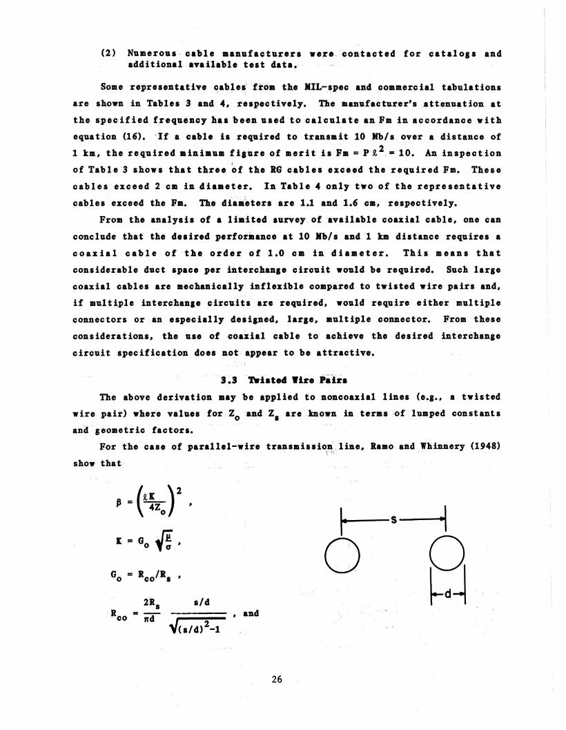
"3~3 "TWist•• Wire PairsThe above derivation may be ap~lied to noncoaxial lines (e•••• a twisted
wire pair) whereval·ues for"Zo'aJl.'d Zs are ,known in ·teras.-of lumped constants
and geometric factors.
Fbr the case of parallel-wire tra:nsllission',line. Ramo and Whinnery (1948)"\' '''i~, '- , "
show that
(R,K )2Ii = 4Z
o'
2Rs sIdR = ---d· - • and
co " ..... 2' V(s/d)-1
26

Table 3. Rep'reseDtativeMIL-Spec Coaslal:, Twillaxial, 'and Triaxial Cables
Cable
CX-112301G
RG8A!U
RG200lU
RGI1A/U
RG318/U
RG59/UTriaxial
Twinaxial
LarS8at ,(4B/tm),· ......Bi.8nsioB (ca) '(at f 0.)
0.43 ;14.81(2)
O~7 66(100)
2.3 23(~O(»
10.7 .751(100)
2.2 13(100)
4.1 7.2(100)
0.8 .85.(100)
0 •.8 134"(100)
'( ~~~l~:~'
Fm(Mpls-km2 )
1.0
2.5
20.6:
1.9
64.5
210.0
1.5
0.6
,;Table 4. Repr••eatative£o•••rc,ial Coa:xial, Cables
0.45
3.6
2.1
6.4
2.1
5.7
11.4
21.0
21

Thus #
R, 2 f.l (s/d)2P = -----.-----
4Z 2n2d2a[(s/d)2_1lo
substituting values for f.l and a for copper#
Let the maximum pulse rate be determined when p 0.1 Pmax = 7.71S:
1p =-pp
If P is in megapulses# d in mm# R, in km# then
and
P = 0.236x10⁻³Z 2d2[(s/d)2_1 ]
o
R,2 (s/d)2
Fm = PR, 2Z 2d2[(s/d)2_1 ]
0.236xl0-3 _0 . _
(s/d)2
(17)
If one chooses d = 0.5 mm and s = 1 mm, this yields
and Fm = 1.10.
This indicates that a twisted-wire pair of about 24 gauge copper wire
will transmit about 1 Mb/s over a distance of 1 km under the condition that
pulse dispersion is the limiting factor. Transmission rates up to 1~44 Mb/s
are achievable with appropriate compensation. (Note: The twisted-wire pair
is equivalent to the parallel-wire transmission line where the period of twist
28

is much greater than the wavelength. The twists reduce 60-Hz pickup and tend
to reduce crosstalk between pairs.)
4. PROPERTIES AND LIMITATIONS OF OPTICAL FIBER WAVEGUIDES
Optical fiber waveguide technology was one of the glamour technologies of
the 1970's, during which time it matured from the experimental laboratory to
commercial implementation in virtually all types of guided-wave transmission
applications. The largest volume applications have been in long-haul and
interexchange trunking by telephone common carriers. Careful attention to
assure cost competitiveness has been exercised in these installations.
Growing use of optical cable for customer local loops and local area networks
(or equivalents) is reported (Schweiger and Middel, 1982), largely' outside the
United States. Numerous manufacturers, in the United States and elsewhere,
offer optical links typically designed for RS-232-C or V.24 transparency.
Similarly, there are commercially available optical links designed to be
compatible with T-carrier hierarchies up to T-3 (44.5 Mb/s). These links do
not offer optical compatibility among various manufacturers since standards
necessary for such compatibility do not as yet exist.
The growing use of optical fibers may be attributed to advantages
tesulting from one or more of several inherent characteristics, such as:
o low attenuation,o high bandwidth,o low distortion,o small size,o immunity to electromagnetic interference,
(and elimination of radiated spurious emissions),o commercial availability of many alternative
fiber and cable configurations,o decreasing cost,o savings in cost of installation, shipping, and storage,o compatibility with digital signals.
This section provides a discussion of these inherent characteristics, and
an analysis of optical cable application for ISDN User/Network Interface
interchange circuits.
4.1 Optical Fiber Waveluide Par~eters
Optical fibers are dielectric waveguide structures that are used to
confine and guide light. Optical fib.rs essentially consist of an inner
29

dielectric material called core, surrounded by another dielectric with lower
refractive index, referred to as cladding. The geometry is circular in cross
section. Other geometries are possible, but the circular symmetry results in
ease of fabrication and handling and allows simpler theoretical treatment.
The most important parameters for specifying multimode optical fiber
properties are: attenuation coefficient; core radius, a; the numerical
aperture, NA = " n12 - n22 (where nl'= core refractive index, n2 = cladding
refractive index); and a characteristic parameter called V = (21Ta/).,)..Jn12 -n22
(where A is the light wavelength in vacuum). The NA parameter is related to
the maximum acceptance angle for rays entering the fiber.
Two important structural and operational characteristics of optical fiber
waveguides need to be considered, namely: step index vs graded index and
multimode vs single mode. The step index fiber consists of a uniform core of
refractive index nl surrounded by a cladding of index n2, with n2 < nl • Such
a step index structure will support, generally, many propagating modes, their
number being approximately equal to V2/2 and therefore proportional to a2 and
to (NA)2. Each mode traverses a different path in the guide and consequently
arrives at the end of the guide at a slightly different time. This results in
signal distortion and therefore limits the bandwidth of the waveguide. This
is a drawback of the step index fiber in the context of long-haul, wideband
telecommunication systems. Practical fibers for such systems exhibit limited
NA (typically NA :: 0.2).
The fiber core radius, a, may be reduced for a given A so that a single
mo.de is propaga ted. The cond i t ion for sing 1e mode prop ag a t ion oc cur s when
v < 2.4. Single mode fibers achieve the ultimate limit of bandwidth
achievable in dielectric waveguides, since only material dispersion (discussed
below) contributes to distortion. The impairing effect of differential mode
delay on bandwidth described above for multimode step index waveguides can be
greatly reduced by suitably varying the refractive index in the fiber cross
section so as to develop a nearly parabolic index profile as a function of
radius, with a maximum on the fiber axis. This provides a variable velocity
for off-axis modes such that all modes have the same group velocity and arrive
at the end of the waveguide at the same time. This graded index minimizes the
time dispersion caused by the multiple modes and improves the resultant
bandwidth over the step index waveguide.
30

4.2 Analytical Description
The theoretical analysis of dielectric wav'eguides may be carried out
using either of two approaches~ namely geometric or modal (electromagnetic).
Geometric analysis produces well-approximated results particularly useful for
providing physical interpretation of results in multimode fib'ers. The
electromagnetic approach is necessary for single- or few-mode fibers and is
necessary for certain phenomena such as coherence or interference. In either
case~ the theory is complex and beyond the scope of this study. Only
qualitative discussions wil'l be presented here. For a summary of the
theoretical approaches based on a recent survey of the literature~ the reader
is referred to a recent book (T~chnical Staff of CSELT~ 1980) where the
theoretical~ measurement~ and system characteristics are described in detail.
4.3 Attenuation Characteristic
Attenuation in an optical waveguide is caused by absorption~ scattering~
and leaky modes. Absorption and scattering are primarily functions of the
purity of the core and cladding material. The ultimate lower limit of these
losses is determined by Rayleigh scattering which is proportional to A-4~~
where A is~ again~ the optical wavelength. In multimode guides~ attenuatiori
may be different for differentmcides (differential mode attenuation). In thi.
case the attenuation coefficient (generally expressed in dB/km) is nota
constant function of distance. Recent advances in materials and manufacturing
techniques have greatl)r reduced the absorption losses in high-quality optical
fiber waveguides. Figure 4 shows a plot of attenuation vs wavelengtho"f- a
typical communications-type fiber with low absorption loss. The attenuation
at A, :: 1400 nm results from hydroxyl ion (On) absorption~ which clan be almost
totally removed~ but at increased production costs.
Extensive work is underway to compare the accuracy and reproducibility of
measurements of attenuation and other characteris'tics (Danielson~ et al.~
1982) and to develop standards for the measurement techniques (e.g.~ EIA
P. 6.6 committee). From the perspective of systems design~ the attenuation
coefficient as measured by the manufacturer is sufficient for calculating
system power margin~ if the measurements are made under carefully standardized
and recognized procedures.
For moderate-bit-rate systems~ the attenuation ultimately reduces the
energy transmitted in a pulse to a level that is not distinguishable from the
noise of the receiver. This condition may determine the maximum length of
31

Figure 4. Attenuation vs wavelength for typical, low loss, silica-core optical fiber.

waveguide that can be used wit.hout repeaters or other amplification.
Attenua tioD of optical fiber must be carefully considered, along with other
losses such as splices", connect.ors, and coupling in system design" in order to
assure adequate system margin.
4.4 BaadwidthCharacteristic
When distortion of the re'ceived' signal, rather than its ampl itude
(power), limits performance of a digital transmission, the system is said to
be operating in the distortion-limited regime. This applies equally to the
optical fiber waveguide and to the metallic transmission lines discussed in
Section 3 above.
For the purpose of this report, it is desirable to look at those
parameters of the optical fiber .aveguide that cause the pulse distortion, and
to develop appropriate rationale for a figure of merit suitable for comparing
various optical fiber cables.
Optical pulses traveling in a multimode optical waveguide are subject to
four primary mechanisms that cause pulse distortion, namely: (1) mul timode
distortion (often erroneously referred to as multimode 'dispersion'), (2)
material dispersion, (3) waveguide disp~rsion, and (4) profile dispersion.
These primary mechanisms and other terms have been defined (Hanson et al.,
1982) by a North American committee.2
The definitions of the mechanisms are:
Multi~ode distortion: in a multimode optical waveguide, thatdistortion resulting from differential mode delay. Differentialmode delay is defined as the variation in propagation delay thatoccurs b ec au seof the d iife ren t group vel oc it i e s of the variousmodes. (Note that mult:'~mode distortion is a time-dependentparameter as oppo,sed to the wavelength-dependence of the followingthree dispersion parameters.)
M~!££i~! 4i~~~£~i~A: that dispersion attributable to thewavelength dependence of the refractive index of material used toform the waveguide. (Note that. this mechanism is independent ofwaveguide geometry and is therefore common to both multimode andsingle mode fiber waveguides.)
2The resultant handbook has been adopted by H~lldards committees of EIA, IEEE,and several international working groups.
33

Waveguide dispersion: for each mode in an optical waveguide. theprocess by which an electromagnetic signal 'is distorted by virtueof the dependence of the phase and group ,velocities on wavelength.as a consequence of geometric properties of the waveguide. Inparticular. for circular waveguides. the dependence is the ratio(a/).,).
Profile dispersion: in an optical waveguide. that dispersionattributable to the variation of refractive index contrast withwavelength. where contrast refers to the difference between themaximum refractive index in the core and the refractive index ofthe homogeneous cladding. Profile dispersion is usually defined bythe profile dispersion parameter. which is that dispersionattributable to the variation of refractive index profile withwavelength. The profile variation has two contributors: (a)variation in refractive index contrast. and (b) variation inprofile parameters.
The profile parameter. g. applies to a class of graded index profiles
characterized by the following equations:
ria
r L a
(18)
where A
n 2_n 21 2
2n 21
and nCr) is the refractive index as a function of radius. nl is the refractive
index on axis. D2 is the refractive index of the homogeneous cladding. a is
the core radius. and g is a parameter that defines the shape of the profile.
Measuring the impulse response of the dielectric waveguide will account
for all of the above delays. This can be accomplished by sending a very short
optical pulse (short in comparison to the total pulse broadening) into the
fiber and observing the output pulse after it has traversed the fiber length.
~. Such a measurement. generally. requires a sophisticated and expensive
light source and 11igh-resolution receiving equipment. If the input pulse is
not short compared with the total pulse broadening, the output pulse is the
convolution of the input pulse and the impulse response of the line. If the
input pulse shape is accurately known, it is possible to deconvolve the input
from the output response and thus obtain the impulse response.
34

4.4.1 Multimode Distortion
Multimode distortion occurs in both step index and graded index
waveguides. Higher-order modes have longer paths in traversing the waveguide
than do lower-order modes, therefore requiring longer transit times. This
results in broadening of the received pulse duration. For engineering
approximations, the maximum value for this differential mode delay and
consequent pulse broadening .in step index waveguides is the difference between
transit time for the highest-order mode, limited by the waveguide's critical
angle, and the lowest-·order mode, corresponding to an axial ray. Measured
values tend to be lowet than calculated values because of the relatively
higher attenuation of high-order modes. Multimode distortion is generally the
dominant cause of pulse distortion for the step index fiber.
4.4.1.1 Step index waveguides
There are a number of measures of performance that describe the
degradation caused by the distortion effects produced by the fiber on the
transmitted signal. The engineering parameter most often measured is the 3-dB
bandwidth. The 3-dB bandwidth is the frequency of modulation at which the
optical power at the output of the waveguide falls to one-half of the output
power measured at zero frequency. Note that this loss in power is independent
of and in addition to the attenuation due to scattering and absorption
mechanisms discussed above. Another measure is the rms impulse response time
of the fiber. This requires a very short duration input pulse. The rms
impulse response is a characteristic that can be calculated. Some engineering
approaches to system design require the distortion characteristic of the fiber
to be expressed in terms of' a rise time response of the fiber. Finally, the
differential delay bet'ween the transit_ time of high-order modes and loy-order
(axial) modes transmitted by the fiber may also be used as a measure of the
multimode distortion. The relationship of these several measures for the
determination of a maximum bit rate x length product is desired here to
develop a figure of merit useful in comparing the performance of different
fiber waveguides.
A general description of the radial variation of refractive index that
characterizes optical fiber waveguides is given by equation (18). Step index
fibers are defined by equation (18) wheng::;~. :.Quantitative expressions for
the impulse response of waveguides that conform to the index variations
35

described by equation (18) have been derived (Olshansky and Keck. 1976).
Neglecting some higher order terms, the result of this derivation is given by
-gg+l (
g+.2 )1/23g+2
g-2g+2 •
(19)
For a step index fiber (g=m), the rms impulse response per unit length is
nlA O.289n1Aa ~ ----- = s/m.
-2c{3 c(20)
To obtain the rms impulse width for a length i, the expression (20) must be
multipliedbYi. Ifiis inkm, the result is
6-r = (J i km = 960 n1 A R,km ns/b. (21)
Thus for step index fiber with nl = 1.4586 (8i02 ), A = 0.01, 61:' = 14 ns/b.
The shape of the received pulse influences the intersymbol interference
effect at large pulse overlap and requires a hisher input power to the
receiver to achieve a given bit error rate (BER) performance. Personick
(1973) has investigated this power penalty for various signal waveform shapes.
His results demonstrate that for about 1 dB penalty in the received power
requirements, one can specify an allowable bit rate x length (regardless of
pulse shape) of
1 1P = - = -- megabits - k.m/s.max T 4&1:'
Thus, for the step index fiber described above.
Pmax = 4x~4 = 18 megabits - b/s.
(22)
4.4.1.2 Graded index waveguides
The general expression describing the radial variation of refractive
index given in equa tion (18) describes the graded index fiber where g is the
parameter that defines the shape of the profile. Note that the impulse
response defined by equation (19) indicates no modal dispersion where g = 2,
the parabolic profile. This is not quite true, and the more precise analysis
contained in the reference (Olshansky and Keck, 1976) leads to an expression
for an 'ideal' round-fiber impulse response:
36

nl 2a· = 0.037 - A-
1 C
n A21z-----
C 20{3·(23)
If A is of order 0~1, this indicates a decrease in multimode impulse response
width of about 1000. A set of normalized rms width of impulse :response for
several index distributions (Miller et al., 1973) is given in Table S. This
table indicates that in practice, improvements of the order of SO:! may be
achievable. Using the value corresponding to the practical parabolic fiber,
and assuming nl = 1.4586, A = 0.01. The resultant 6~ for graded index is
&~gi = 0.3 ns/km.
This corresponds to a maximum bit rate x length product,
Pmax = 833 Mb-km/:5.
(24)
(25)
This number serves mainly to indicate that material dispersion discussed
below will likely dominate in well-designed graded index fibers.
In practice, the contributions of both multimode distortion and material
dipersion must be considered.
4.4.2 Material Dispersion
Material dispersion occurs in all fibers because the index of refraction
varies with wavelength. It becomes more important when a source of wide
spectral bandwidth such as a light emitting diode (LED) is used as a source.
A reference paper (DiDomenico, 1972) treats the effect of material dispersion
and its relationship to information bandwidth of the f'iber. An expression is
derived for group delay in terms of known parameters of the glass used for the
waveguide. This derivation appears to provide approximations which are useful
for engineering practice and are complementary to the above intermodal
approximations derived by Gioge (1971).
37
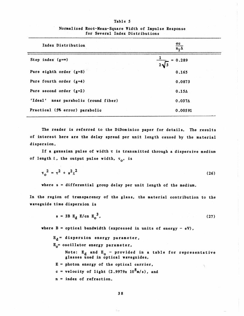
Table S
Normalized Roc,t-Mean-Square Width of Impulse Responsefor Several Index Distributions
= 0.289
Index Distribution
Step index- (g=(X»
Pure eighth order (g=8)
Pure fourth order (g=4)
Pure second order -(g=2)
'Ideal' near parabolic (round fiber)
Practical (5~ error) parabolic
1
2{3
acn1A
0.165
0.0873
0.15A
0.037A
0.00591
The reader is referred to the DiDominico paper for details. The results
of interest here are the delay spread per unit length caused by the material
dispersion.
If a gaussian pulse of width ~ is transmitted through a dispersive medium
of length~, the output pulse width, ~o' is
where s = differential group delay per unit length of the medium.
In the region of transparency of the glass, the material contribution to the
waveguide time dispersion is
3s = 3B Ed Elcn Eo '
where B = optical bandwidth (expressed in units of energy - eV),
(27)
Ed = dispersion energy parameter,
Eo= oscillator energy parameter,
Note: Ed and Eo - provided in a table for representativeglasses used in optical waveguides,
E = photon energy of the optical carrier,
c = velocity of light (2.9979x 10⁸m/ s ), and
n = index of refraction.
38

Equation (27) applies for a pulse whose spectral width is slDall compared to
the emission spectrum of the source (i.e., &1 « .lo) or for a bandwidth
limited gaussian pulse. In the first case, B .is the spectr.al width of the
source (expressed in units of energy) while in the second case (below), B is
the reciprocal of the pulse width, i.e., B=h/-.:, where h is Planck's constant
(h = 4.14- x 10-lS eV-s) and 't is the pulse width of the source in seconds.
For a broadband source (e.g_, an LED), case 1 above, which transmits a
wide pulse,
s~3 (28)
and for Si02 , this bec~omes
s ~ 170&A
(ns/km)."'0
The desired delay spre:ad is
&'"S R,km = 1 70 A ~ km ns '.
o
(29)
(30)
For a bandwidth-limited .pulse (i.e., 't ~ sL) and 6A very small compared
to "'0 such as a mode-locked laser, case 2 above,
and for 8i02
s~ 0.35 x 10⁻¹² ns/km,"C
where "C is expressed in seconds.
Substituting "C = sf'km'
s = (0.35 x 10⁻¹²
)1/2 •R. km x 109
39
(31)
(32)
(33)

The desired delay spread is
s ~ km = 18"'~b1 ps.
Note that for a bandwidth-limited pulse, the material dispersion increases as
the square root of len.gth.
An LED source might have a (B/E) ratio (source spectral width! source
center wavelength) ofl percent. The material dispersion would then be about
1.7 ns/km from equation (30). For very short laser pulses, pulse spread of a
fiber is about 18 ps for a l-km length for material dispersion.
In the discussion of multimode distortion, it was stated that the rms
width of the impulse response is ne~ded to calculate the informBtion bandwidth
of the fiber. Note that in the discussion above, the information bandwidth
was taken to be the reciprocal of the pulse spread caused by material
dispersion. An analysis (Miller et al., 1973) based on the impulse response
of the fiber and assuming a gaussian spectral shape of the input pulse yields
a value for the rms width of the impulse response for an AIGaAs LED and fused
silica fiber of 1.75 ns/km, compared with the predicted value above of 1.7
ns/km. tTsing the relationship (Personick, 1973) between rms width and maximum
bit rate, gives a pulse rate x length product of 142 Mb-km/s.
In multimode fibers. each mode experiences a different group delay but,
to a good approximation, the same differential group delays. This group delay
must be added to the multimode distortion to determine the envelope delay.
4.4.3 Relation of Bandwidth and Impulse Response
For any given impulse response shape, there is a constant such that:
f(3-dB) arms = constant.
If the impulse response shape of the fiber is gaussian, this relationship
has been shown (Danielson, 1982) to be:
fa = 190,(3-dB) rms
where f(3-dB) = lowest frequency at which the optical power is onehalf the power at zero frequency (MHz/km),
and arms = impulse response width of the fiber (ns).
40
(34)

Exper imental measurem en ts (Buckl er, 1982) have shown tha t for several
graded index optical fibers, the above constant is 169 ± 11. This would
indicate that the shape of the impulse response is relatively uniform among
the several fibers tested.
The maximum pulse rate x distance relation from equation (22) may be
expressed in terms of the f(3-dB) response, assuming a gaussian impulse
response shape, by combining equation (34) and (22):
Pmax = 1.3 £(3-dB) )~-km/s. (35)
4.4.4 Rise Time (RT) Approximation
The detection circuitry of an optical receiver is often modeled as a
resistance-capacitance (Re) single-pole filter having a time constant te. The
output waveform, for a square wave of amplitude Am and duration T, is given
by:
ret) = Am [l-exp(-t/tc)], °itiT
= A' exp (-t-T)/tc, Tit,m
where A' = [l-exp (-T/tc)], andm
(36)
tc = a time con,stant characteristic of the receiver.
From this expression, a rise time, RT, defined as the time for the f(t)
to change from 10 percent to 90 percent of Am can be determined, namely
RT = 2.2 tc. (37)
The frequency spectrum of the output pulse can be obtained via the~
transformation
F(w) = j f(t) up (-jwt) dt.-CD
The result is
F(w)
• edTT S1n -2 1
= A T (. ~)6~ exp -J 2 edT l+jedtc·
"2
41
(38)

The last term of this equation determines the amplitude effect of the
resultant low-pass filter. The frequency at which the power response is down
by 3 dB can be determined as:
1 -"1 + (2n f(3_dB)tc)2
1-{2
Combining equations (37) and (39). one obtains:
RT = 0.35 •f(3-dB)
(39)
(40)
Equation (40) is sometimes used to relate the rise time of a fiber to its
f(3-dB) bandwidth:
350RT (ns-km) = ~--.f (3-dB) (MHz-km)
(41)
This is properly the characterization of a single pole RC filter and may not
characterize the optical fiber response.
4.5 ....~ ..4 Coaol••ioDS
A complete analysis of the optical fiber waveguide using either the
Maxwell field-equation approach or the somewhat more approximate geometric
optic approach is quite coaple~. A search has been made of referenceable
literature for appro~i.ate equations that provide a basis for relating the key
parameters published by manufacturers to the fundamental performance
characteristics of step index and araded index optical fibers. Single mode
fibers have been mentioned in the context of material dispersion limita~ions,
but no attempt has been made to characterize the limiting performance of this
promisinl waveguide. This is because the extremely high bandwidth obtainable
with sinlle aode waveauides is not required for applications considered here,
and economical sources such as LED's are Dot practical for use with these
fibers. because of the LED's inherent near-Lambertian emission.
The properties of the multimode optical fiber waveguide that affect its
limiti~s perforaance as a transmission medium are attenuation and bandwidth.
The attenuation is ultimately limited by Rayleigh scattering from very small
42

discontinuiti,es in the core, mater'ial'and a~bsorp,tion losses caused by trace
impurities in the material. The Rayleigh scattering is proportional to A,-4
and is therefore less at longer wavelength.s ,(i.e.1 1300 and 1500 nm).
Bandwidth is dominated generally by intermodal distortion in step index fibers
and by ma ter i a I d i spe r s ion in sing 1 e mode f i be r s. Gx aded index f i be r scan
provide a bandwidth increase of about SO times that of step index fibers under
practical conditions.
Measurement procedures are receiving much attention by standards
committees, and methods should be accepted in, ,the near f'llture to provide both
precise and well-defined parameters for use in engineering design. Procedures
for measuring attenuation are now being compared by leading laboratories
(Danielson et al. 1 1982) with good results. The greatest uncertainty in
making bandwidth measurements on mtil timode fibers is the lack of '$tandardized
launching conditions.
In section 3 1 a figure of merit was defined [e,quation (1)] as Fm = P ~u.
The P in this equation is the maximum pulse ratefor~acceptableoverlapof
successive pulses. The exponent l U I identifies the relation of pulse
distortion to length. In multimode fibers l ' th"e impulse response is
proportional to length [equation (21)],' therefore
Fm = Pmax ~ km (42)
(43)
For a typical step index fiber l Fm = 18 [e,quat:'i~oin{22)]. For a practical
optimum graded index fiber. Fm = 833 [equation(25)]. For a transmission
requirement of 10 Mbl sand 1-km length,' the requiredFm = P ~ = 1.0. Thus I the
step index exceeds the requiremen~. The graded index fiber exceeds the
requirement by nearly a factor of 100--a major overkilll
For the special case of 8' bandwidth-limite:d pulse, the material
dispersion is proportional to.y;:. In this case (e.g •., mode-locked laser
source)1
Fm = Pmax {7:Thus~ the figure of merit [equation (1)] applies to optical fiber
waveguides as well as to metallic cables. Formultimode fiber'sl u = 1~ and
for single mode fibers with an optimum inp_ut~.'uise, u = 1/2.
43

The approximations presented here are useful in comparing the performance
of different optical waveguides and in computing a figure of merit for a
particular application. A corresponding figure of merit for available
waveguides can be computed from manufacturers' specifications to determine the
acceptability as a transmission medium for the particular application. These
aproximations indicate that, formultimode distortion, the critical parameter
values needed for comparing performance are the core index and a steady state
NA. For strongly overmoded guides, the distortion is dominated by the NA of
the guide. It is therefore important to know what effective NA was used in
any measured bandwidth specified by the manufacturer.
5 • DCBNOLOGY READINESS OF SOBSYSTBJI COJIPONENrSFOR OPTICAL FIBER INTERCHANGE CIRCUITS
Preceding sections of this report have dealt with analysis of optical
fiber waveguide capabilities for meeting technical requirements for next
generation DTE/DCE interchange circuits. This section presents examples of
commercial subsystem components. that, based on manufacturer's specifications,
fulfill these technical requirements.
Specific subsystem components addressed are optical fiber cables, optical
transmitter modules, and optical receiver modules. Technical analyses of this
report are specifically limited to the transmission medium which" for the
optical regime, consists of the cabled optical fiber(s) and associated
connectors. However, to characterize the optical fiber real istically, it is
necessary to consider characteristics of commercial electro-optic transducers
that constitute system interfaces to the optical cable. The transmitter and
receiver modules consist of these transducers and the minimal electrical
circuitry required for electrical interfacing to the DTE and DCE.
Performance data tabulated below for commercial hardware are taken
directly from manufacturers' product data sheets. To ensure broad coverage of
suppliers, a commercial survey of fiber optics manufacturers and vendors
(Laser Focus, 1982) was used. A total of 72 suppliers was identified as
marketing potentially applicable hardware; all were contacted for technical
data. Many products represented by the above survey were not pertinent to
interchange ci~cuit application. The majority of those found pertinent did
meet (and usually exceeded) the maximum requirements identified by this study.
44

These data were supplemented by contacting other vendors through trade
journal advertisements and by contacts at major trade shows through spring
1982. Because the tec:b.nical information obtained from foreign suppliers was
inadequate for representing a broad cross section of foreign products, the
tabulations contain performance data on only U.S.-manufactured cables and
devices.
5.1 Optical IDterchaDle Circuit Desiln Considerations
The transmission performance requirements of 10 Mb/s x 1 km for BER
i 10-9 , chosen earlier in this report for analytic characterization of
metallic and optical fiber interchange circuits, were used for evaluation of
commercial optical hardware. These minimum performance limits have been based
on current CCITT deliberations for ISDN User/Network Interface requirements
(see Section 1.4). Both the preceding technical feasibilty analysis and the
following survey of technology readiness indicate that communica,tions-grade
optical fibers can and do measurably exceed these selected values for the
performance parameters. This frees the designer and user to select from
various manufacturers and among numerous fiber configuration options, all of
which offer the optical fiber's fundamental advantages of galvanic isolation
and EMI isolation.
5.2 Co..ereial Optical Fiber Cables
The commercial optical fiber cables whose characteristics ;lre shown in
Table 6 were selected based on the following minimum requiremeJlts: 10 )Ib! s
transmission over 1 km with attenuation coefficient not to exceed 10 dB!km for
the 800-900 nm spectral window. The minimum bit error rate specified for this
study was omitted, because BER -- a specification for the electrical signal -
is not applicable to the optical transmission medium per see (Bit error rate
is addressed as a parameter for the optical subsystem, including transmitter
and receiver, in the following section.)
All values shown in Table 6 are from (U.S.) manufacturers' ptLblished data
sheets. Values are shown for bandwidth (MHz-km) rather than for bit rate
(Mb/s), since ~he BW designation is employed by fiber and cable manufacturers,
who typically use a sinusoidal waveform for measurement of optical pulse
spreading to spec ify throughput bandwidth.. Using the de:rivation of
Section 4.4 of this report, maximum bit rate = 1.3 (3-dB BW).
4S

Table 6. Representative, Commercial Optical Cable Characteristics
Mfgr./ Maximum Core )Iinimum Minimum Fiber IndexSupplier Attenuation Diameter NA BW Material Profile
Coefficient 2aa
(a) (b) (b) (c) (d)
(dB/km) (Jim) (MHz-kin)
1 6 200 0.17 45 S
2 4 SO 0.20 100 S G
11 4/8S0 nm SO 0.2 225 S G3/1300 nm
3 8 SO 0.20 200 S G
3 10 100 0.30 20 S SG
11 S SO 0.2 400 S G
4 4 SO 0.2 200 S G
4 7 100 0.3 20 S SG
11 5/850 nm4/1300 nm SO 0.20 SOO S G
8 10 200 0.3 20 PCS SG
11 6/8S0 nmS/1300 nm 100 0.28 100 S G
8 6 200 0.4 20 PCS SG
8 7 SO 0.2 200 S G
3 8 200 0.27 2S PCS SP
9 6 80 0.30 200 SG
S 7 100 0.22 200 S SG7 8 200 0.33 103 8 300 0.27 20 PCS SP
8 10 100 0.3 20 S PG
6 6 200 0.21 200 PCS SP
10 6 100 0.20 100
Notes:a Codes for manufacturers/supplies are assigned randomly.
b Attenuation and BW for 8S0 nm unless otherwise specified in table.
c Fiber-material designation: S = all silica, PCS = plastic-clad s il iea.
d Index profile designators: G = graded index, SG = semigraded (partiallygraded) index, SP= step index.
46

The selection of a maximum value of ~OdB/ltm.for attenuation coefficient
is arbitrary. There is no standardization of values for 'high' or 'low'
attenuation for cabled fibers.: but;·there -is a growing tendency in the
literature to classify those with attenuation coefficients above 6 dB/km (for
the 800-900 nm spectral range) as high-loss fibers (Hume. 1982). Most such
categorization is in terms of long-haul trunking requirements. where maximum
attenuation of approximately 3.5 dB/km (at 800 nm) for concatenated paths is
highly desirable (op. cit.) to reduce repeater spacing. As indicated in the
following section. simple. commercial transmitters and receivers are capable
of operation with 10 dB/km (and even higher) fiber attenuation for 1-km paths.
Thus, consideration of fibers with the higher attenuation permits broader user
options for cost tradeoffs.
Among the product offerings of U.S. manufacturers. many optical fiber
cables were identified that met the above broad requirements. In fact. only a
few did not fulfill these requirements. The representative cables shown in
Table 6 were selected, to minimize the size of the tabulation, using the
following criteria:
(1) conformity with the minimum 10 Mb/s x 1 km. maximum 10 dB/kmrequirements,
(2) for each manufacturer, elimination of special~purpose cable options(e.g., armoring) for identical fiber configurations (a.11 cables inthe table are all-dielectric construction). and
(3) for each fiber configuration produced by a given manufacturer,selection of the lowest cost option. This often. but not always,resulted in fibers of higher attenuation.
Since all of the fiber cables in Table 6 -- and most of those surveyed -
meet or exceed requirements of this study. the user has many acceptable
options among fibers with widely varying physical dimensions. numerical
aperture, and attenuation coefficients. Most manufacturers represented in the
table offer off-the-shelf cables with numbers of individual fibers compatible
with various proposals for numbers of interchange circuits for the ISDN
User/Network Interface.
The primary requirements for long~haul trunking --appreciably higher bit
rate x path length products and lower attenuations than required for this
application -- have res,ulted in de factoprel~ID:.~nary standardization of graded
index, SO flm-core, low-attenuation fibers with anNA of approximately 0.2.
These parameter values are useful also for the DTE/DCE interface. but are far
47

from optim'um for this short-haul application in terms of optical power
acceptance (light-gathering) efficiency. Little attention has been given in
the literature to characterizing fiber efficiency for short-haul links. An
approach is presented here for comparison of f ibe rsw ith various physical
configurations. To make such comparisons, it is essential to have previously
ascertained that all fibers under consideration are not bandwidth limited for
the proposed application. The primary parameters of concern are:
o core radius, a relative measure of power acceptance efficiency thatis proportional to fiber cross section, or radius squared,
o NA, the angular measure of acceptance efficiency, also a squareddependency, and
o attenuation coefficient .. the measure of throughput efficiency.
To compare two different fibers characterized in terms of these three
parameters, the term relative power throughput, po, is used for the optical
power level at the fiberts exit end:
where POr = the optical power available at output end of the fiber of thelast row in Table 7, normalized to 0 dB t~ permit presentation ofvalues in dimensionless units,
POn power at output end of any other fiber,
NA = fiber numerical aperture,
a = fiber core radius in Jlm,
a = fiber attenuation coefficient in dB/km,
5l, path length in km,
subscript r = arbitrary reference fiber, and
subscriptn any other fiber, for comparison purposes.
The above expression is empirical, but it does serve to form a basis for
comparison among dissimilar fibers. The power throughput value for cable
No. 19 of Table 7 was arbitrarily normalized to 0 dB to permit presentation in
that table of relative values in dimensionless units.
48

Table 7. Relative P·ower Throughput for Representative,Commercial Optical Cables
Mfgr./ NA RelativeSupplier ·(L,ow Core Attenuation Power
Wavelength Diameter Coefficient ThroughputWindow) 2a a (See Text)
(flm) (dB/km) (dB)
1 8 0.4 200 6 20
2 3 0.27 300 8 18.2
3 6 0.3 200 6 17.6
4 7 0.33 200 8 16.4
5 3 0.27 200 8 14.6
6 8 0.3 200 10 13.6
7 1 0.17 200 6 12.6
8 11 0.28 100 6 10.9
9 4 0.3 100 7 10.5
10 9 0.3 80 6 9.6
11 10 0.2 100 6 8.0
12 S 0.22 100 7 7.8
13 3 0.3 100 10 7.5
14 8 0.3 100 10 7.5
IS 2 0.2 SO 4 4.0
16 4 0.2 50 4 4.0
17 11 0.2 SO 5 3.0
18 8 0.2 50 7 1.0
19 3 0.2 SO 8 0
(ArbitraryReference)
Note:Above cables are from Table 6. In all cases, manufacturers' publishedbandwidth exceeds requirements for this study.
49

This reference fiber. with 50-J.lm core and NAofO.2, represents a typical
design for high-bit-rate. long-haul trunking applications, even though the
attenuation of 8 dB/km is relatively high. It is seen from row 2 of Table 7
that a fiber of 300-Jlm core. the same attenuation coefficient~ and similar NA
yields an 18.2 dB increase in power throughput efficiency -- almost
exclusively due to the increase in core size. The 200-~m-core fiber of row 1
offers 20 dB relative efficiency improvement with its very large NA of 0.4 and
attenuation of 6 dB/km.
Numerous similar tradeoffs are possible for the various fiber design
configurations of Table 1. Transmission at 10 Mb/s for a l-km path is a
modest requirement for optical fibers. permitting use of large cores and NA's,
thus relaxing attenua tionrequiremen t s. Costly, prem ium-grade fibers c with
ultra-low losses are not required for interchange circuit applications. The
high relative throughput efficiency of large-core, large~NA fibers of moderate
loss is of paramount importance in establishing optical power values fQr the
interfaces between the transmission line and optical source and detecto~ Use
of high-efficiency fibers will permit cost tradeoffs involving optical
transmitters of reduced power output and receivers of modest sensitivity as
compared to that zequiredfor coupling to fibers designed for long-haul
trunking.
Caution must be exercised. however~ in making such comparisons, to ensure
that the manufacturer's stated value for NA is for measured~ steady-state NA
-- not a value calculated from core and cladding indices. This is especially
important for large NA's, where radiation losses and mode mixing of higher
order modes typically result in considerable -- often drastic -- decrease in
steady-state values. as compared to calculated (acceptance) values. For
example, manufacturers' data for some fibers with a calculated NA of 0.4
indicate a steady-state value of 0.27. measured at 0.5 km.
For Table 7, manufacturers' values for NA have been used~ a,ssuming
measured data. Analysis of bandwidth capabilities of those fibers indicates
that. in some cases. the assumption may have been incorrect. This emphasizes
the need for standardized measurement conditions to provide the user with
adequate information for comparability among various fiber designs as well as
among various manufacturers' products.
50

One factor that hasbe~nign~red in the approximations of the above
comparisons is the difference in collection efficiency between otherwise
similar step index and graded in,dex, fibers. For the same NA and core
diameter~ the step index design accepts approximately 3 dB more optical power
than does the graded index fiber (which offers approximately an order of
magnitude higher bandwidth). (Collection efficiency of the semigraded fiber
lies between that of the graded and step index designs.) Thus step index
fibers~ which tend to be less expensive~ are viable alternatives for the
proposed 10 Mb/s x I km application.
This study has not addressed fiber~to-fiber coupling (connectors~
bidirectional couple%'s~ or splices). primarily because ithasi assumed an
uninterrupted. point-to-point transmission link. Such. a lin,e. however, will
be end-connected, quite probably to optical source and detector fiber
pigtails. And~ realistically~ the user must not be prohibited from using
intermediate connections with other fiber cables. In addition to mechanical
considerations (e.g., fiber-to-fiber alignment~ core and cladding dimensions),
index profile is an important intrinsic coupling-loss' parameter for all such
connections.
To minimize coupling losses resulting from mating fibers having non
identical index profiles. one must assure. in some way~ that profiles of the
mating fibers are similar. For the step index design-~ ,this should prove to be
relatively straightfOirward~ such as specification of ± deviations in index
over a stated percentage of fiber core diameter. For the graded index design.
index specifica tion is more complex. lAs an al terna tive approach~ one might
consider specificati40n of fiber bandwidth toa (high) level such that a
nominally parabolic profile would be required'. This will result i.n minimizing
coupling losses (private communication~G.Day).
For the proposed requirements of this study~ the step index profile
offers adequate bit rate x path length product, provides improved collection
efficiency over the graded index d.sign, and i~ more amenable to coupling
standardization which should yield minimal and predict'able throughput coupling
losses.
5.3 Co..ereia! Optical Traasaitter/Reeeiver K04ale.
To ascertain technology readiness of optibal fiber hardware for DTE/DCE
interchange circuits, it was necessary to investigate commercial availability
51

of transmitters and receivers for interfacing to the optical cable.
Commercial U.S. products were identified by the process described above for
optical cables.
Two broad types of hardware were identified on the U.S. market as of
spring 1982:
(1) Optical links, consisting of relatively sophisticated transmitterand receiver packages including multiplexers/demultiplexers designedto time-multiplex various numbers of electrical channels over asingle optical fiber in each direction, usually for a l-km path.Electrical compatibility is typically for RS-232-C, with V.24 as anoption. Specified optical cables and connectors constitute a partof the system's packaging.
(2) Relatively simple transmitter and receiver modules, consisting ofelecto-optical transducers and the minimal electrical circuitryrequired for TTI.,electrical interfacing compatibility. Package sizeis as small as 43.4 mm x 16.5 mm x 7.9 Mm. Ma tched transmitter andreceiver (and one transceiver model) modules are specified formating to fibers of one or more geometries, and are available withor without the optical cable.
Commercial availability of the former, more sophisticated RS-232-C/V.24
links for DTE/DCE interconnection shows technology readiness of ,optical fiber
subsystems. Specifications of the latter more simple transmit/receive
modules, however, are more amenable to a subsystem analysis to indicate how
fiber geometry variables affect power throughput.
Values for performance parameters of concern to this study are given for
commercial transmit/receive modules (type 2 above) in Table 8. All data are
from published manufacturers' data sheets. Those few models which did not
meet minimum requirements of 10 Mb/s transmission over a 1-km path at BER .5.10-9 have been deleted from the tabulation. All transmitters employ LED
optical sources and all receivers use PIN photodiodes, operating in the 600
900 nm spectral range. These transducers are far less expensive than the
higher power injection laser diode (ILD) sources and higher sensitivity
avalanche photodiode (APD) detectors. Since manufacturers' specifications for
the LED/PIN modules prove adequate for l-km interchange circuits, for a broad
spectrum of commercial optical cables, modules usingILD/APD combinations have
not been considered for this application. The best-case receiver sensitivity
(Table 7) of -40 dBm maybe compared to the ideal theoretical sensitivity of
-51 dBm for a PINphotodiode operating at 10 Mb/s for BER = 10-9 (Personick,
1973) •
52

U1W
Table 8 (Sheet 1 of 4). Digital XMTR/RCVR Modules for Optical Transmission(de to Min 10 Mb/s) Over One Kilometer at BER < 10-9
-
Optical Power
XfllTR RCVR
Module Bit Rate Max. Output At Specified Fiber-Coupling Threshold_gar Reference Code:Type or Parameters BER < 10 Mfgr./ModelBW
dBm (lJW) dBm (lJW)
XMTR 0-25 MHz -7 (200) Typ. 200 lJm-core fiber IManchester Output NA 0.48
RCVR 0-25 MHz -31 (0.9) I
XMTR dc-20 Mb/s -11 (79) Into 200 ~m-core fiber JNRZ
RCVR dc-20 Mb/s -27 (2) JNRZ
XMTR dc-55 Mb/s -4.9 (320) Into 300 ~m-core, NA = 0.22 (SI) ANRZ -6.5 (220) Into 200 11m-core, NA = 0.36 (SI)
-14 (40) Into 100 lJm-core, NA = 0.22 (GR)
RCVR dc-42 Mb/s -28.2 (1.5) ANRZ at 0-20 Mb/s,
NRZ
Transceiver dc-20 Mb/s -17 (20) Into 50 11m-core, NA = 0.20 LNRZ
dc-50 Mb/s -35 (0.32) LNRZ

()1~
Table 8 (Sheet 2) continued
Optical Power
X~1TR RCVR
Module Bit Rate Max. Output At Specified Fiber-Coupling Threshold_gor Reference Code:Type orBW Parameters BER < 10 Mfgr./Model
dBm (llW) dBm (llW)
XMTR dc-50 Mb/s -7 (200) Into 200 llm-core, NA = 0.36 HNRZ
RCVR dc-50 Mb/s -23 (5) HNRZ
XMTR dc-20 Mb/s -4 (400) Into 200 llm-core, NA = 0.3 PNRZ
RCVR dc-20 Mb/s -27 (2) PNRZ
XMTR 0-32 r~b/s 0.75 W/ 19 dB link budget for 200 llm- BNRZ steradian/ core, NA = 0.3, including
cm 2 for input coupling losses300 llm source(microlensed)
RCVR 0-32 Mb/s -31 (0.75) BNRZ
XMTR dc-25 ~~b/s -8 (160) Into 100 llm-core, NA = 0.3 CNRZ
~ ,';hU
RCVR dc-25 Mb/s -24(4) CNRZ

o-Jo-J
Table 8 (Sheet 3) continued
Optical Power
XMTR RCVR
~1odul e Bit Rater~ax. Output At Specified Fiber-Coupling Threshold_gor Reference Code:Type or
BW Parameters BER < 10 Mfgr./Model
dBm (ll~l) dBm (llW)
XMTR dc-20 Mb/s -13 (50) FNRZ pigtail output
RCVR dc-20 Mb/s -33 (0.5) FNRZ
XMTR dc-20 Mb/s -16 (25) GNRZ pigtail output
RCVR dc-20 Mb/s -33 (0.5) GNRZ
XMTR dc-50 Mb/s -3.5 (450) Into 200 11m-core, NA = 0.22 DNRZ
RCVR dc-50 Mb/s -20 (10) 0NRZ
XMTR dc-10 Mbd -10.7 (105) Into 100 11m-core, NA = 0.3 MNRZ pigtail output
100 11m, NA =0.3
RCVR dc-10 Mbd -40 (0.1) MNRZ

U10)
Table 8 (Sheet 4) continued
Optical Power
XMTR RCVR
Module Bit Rate Max. Output At Specified Fiber-Coupling Threshold_~or Reference Code:Type or Parameters BER < 10 Mfgr./ModelBWdBm (l1W) dBm (llW)
XMTR dc-20 Mb/s -8 (160) pi gta i 1 Into 100 11m-core, NA = 0.3 0NRZ -14 (40) pigtail Into 50 11m-core, NA = 0.21
RCVR dc-20 Mb/s -27 (2) 0NRZ
XMTR dc-20 Mb/s - 13 (50 ) pig ta i 1 Into 100 11m-core, NA = 0.3 NNRZ -17 (20) pigta i 1 Into 50 11m-core, NA= 0.21
RCVR dc 20 Mb/s -27 (2) NNRZ

Optical fiber specifications of Table 8 are quoted f:rom module
manufacturers' data. Availability of this type of data, giving oJ.tical power
coupled into a specified fiber geometry, reflects the growing maturity of
fiber optics hardware and consequent providing of information in a form that
is readily meaningful to the user. The LED, in its simplest physical form,
approximates Lambertian emission as an optical source, and its output is
typically expressed in watts per steradian per square meter, the units for the
radiometric term 'radiance'. Using such values to compute the amOllnt of power
that can be coupled into a fiber of specified core diameter and NA can be an
interesting exercise. Recently, manufacturers have made available transmitter
assemblies that employ various techniques for optimizing LED-sou:rce-to-fiber
coupling, and now typically quote values for power coupled into a specified
fiber, rather than leaving that problem to the systems designer/user.
The modules listed in Table 8 use various such coupling techniques,
which include integral fiber pigtails (short fibers, usually proximity-butted
to the LED), micro lenses, and custom-shaped emitting areas of tIle LED -- or
combinations of these. This permits the specification of optical output in
engineering terms of power coupled into a specific fiber geometry.
5.4 Power Budget Exa.ples for Co..ercial Fiber OpticsSubsystea Co.poDeDts
The preceding sections have given characteristics of commercial optical
fiber cables and transmit/receive modules whose specifications meet
requirements of this study. Table 9 presents some examples of power
throughput, using manufacturers' data, for several combinations of these
modules and fibers. The table was compiled in the following manner:
o Each column gives data for a matched transmitter/receiver modulepair by a common manufacturer. Values for transmitter output (rowIII) and relceiver threshold sensitivity (row VIII) are frommanufacturers' data sheets. All transmitters use LED's, and allreceivers employ PIN photodiodes.
o Fiber geometry parameters (rows I and II) are those spec ified bymodule manufacturers for transmitter output coupling.
oAttenu a t ion 'val u e s for row I V are the lowes t val u e s for the abov especified geometries, from Table 6 (not the lowest available).
o For row VI, the 2-dB coupling los/ses (including connectors andfiber-end Fresnel losses) and 3-dB long-term system degradationlosses are arbitrary but reasonable.
57

01co
Table 9. Optical Power Budgets for Commercta1 Digital XMTR/RCVR Pairs as Functionof Commercial Optical Cable Parameters (Transmission Cond~tions:
dc to Min. 10 Mb/s (NRZ) Over 1 Kilometer at BER ~ - )
UnitI Fiber Core Diameter lJm 50 100 200 300
II Fiber NA -- 0.20-0.22 0.30 0.21 0.·30 0.33-0.36 0.40 0.22-0.22
III Max. XMTR Optical Power dBm -14 -17 -10.7 -14 -8 -13 -16 -3.5 -2 -11 -4 -6.5 -7 -5.5 -4.9Coupled into Fiber
IV Cabled-Fiber Attenuation dB 3 7 6 10 6 8(for 1 Km)
V Optical Power Out of dBm -17 -20 -17.7 -21 -15 -20 -23 -9.5 -12 -21 -14 -16.5/-17 -11 .5 -12.91-Ki1ometer Cable
VI Coupling Losses (2 dB) & dB 5 5 5 5Degradation Budget (3 dB)
VI I Max. Optical Power Avai1- dBm -22 -25 -22.7 -26 -20 -25 -28 -14.5 -17 -26 -19 -21.5 -22 -16.5 -17.9able at RCVR
VII I RCVR Threshold dBm -28.2 -35 -40 -27 -24 -33 -33 -20 -31 -27 -27 -28.2 -23 -31 -28.2
Excess Power Margin forAbove Confiquration dB 6.2 10 17.3 1 4 8 5 5.5 14 1 8 6.7 1 14.5 10.3
IXMatched XMTR/RCVR Mfgr. -- A,O L,N M J C,O F,N G D B J P A H I A

o Subtraction of the above losses from transmitter output values ofrow III gives optical power available at output of the 1-kminterchange circuit, in row VII. Comparison of these power levelswith the rece:iver thresholds of row VIII yields the excess powervalues of row IX, which are seen to range from 1 to 17.3 dB abovelevels required for individual receivers.
It may be concluded from the data of Table 9 that there exist numerous
combinations of commercially available optical fiber cables and relatively
simple transmitter and receiver modules that meet proposed requirements for
DTE/DCE interchange circuits. These requirements are modest for the tabulated
subsystems. As seen from Table 9, all fiber/module combinations yield excess
power margin, and use of 10'wer-loss cables would permit increasing all of
these values. With one exception, the transmitter/receiver pairs are rated
for maximum channel capacities ranging between 16 Mb/s and 50 Mb/s, for bit
error rates from 10-9 to 10-15 over 1 kilometer. For operation at 10 Mb/s,
quality of performance of those devices will be proportionately better. Since
interface standards do not yet exist, matched transmitters and receivers must
be purchased from a common manufacturer.
5.5 S.....ary
The preceding discussioIJ. documents commerc ial ava il ab il i ty of numerous
options among optical fiber cables and optical transmitter/receiver modules
whose performance meets or exceeds interchange circuit requirements compatible
with proposals for the ISDN User/Network Interface. The data of Table 8 above
do not constitute results of a system design study, but· rather an indication
of what can be accomplished with user-option combinations of off-the-shelf
hardware. None of these combinations is recommended for the DTE/DCE
application, but all should work, meeting or exceeding proposed minimum
requirements. The optimum subsystem for this application has not been
designed. Until standards are developed to specify both optical and
electrical interfaces, the user must procure transmitters and receivers from
the same manufacturer to en.sure compatibility. The user must also procure
optical cable that meets coupling geometry and attenuation specified by the
transmitter/receiver manufacturer.
Sections 1 and 2 a.bove indicate the strong CCIT!' preference for the two
interchange-circu.it approach for the ISDN U$erlNetwork Interface, with time
multiplexed data, control, and timing signals. A two-fiber optical cable, one
of the most common commercial configurations, meets this requirement,
59

providing a single fiber for all information transfer in each direction. This
approach is typically used in off-the-shelf optical fiber links offering
ser ially mul t ipl exed transm ission of RS-232-C- and V.24-compa tible channel s.
Various other mul tifiber cable configurations ar~, available.
Optimum fiber-per-cable efficiency is achievable by using a single fiber
for bidirectional transmission. This full duplex, one-interchange-circuit
concept can be achieved using optical wavelength division multiplexing (WDM).
In WDM, multiple optical signals 'are transmitted simultaneously and
independently, at different optical wavelengths, over a single fiber. Improved
attenuation of fibers at wavelengths out to A ~ 1.5 ~m permits use of several
low-loss optical 'windows' for WDM. The complexity of WDM results from
requirements for optical multiplexing and demultiplexing, using reflective,
dispersive, or refractive equivalents of optical beam splitters to insert and
extract the distinct optical signals.
Considerable laboratory work has been devoted to advanced WD:&f technology
(Campbell et al., 1980 Fitch et al., 1982; Nicia, 1981; Aoyama and Minowa,
1979; and Watanabe and Nosu, 1980). Som~ commercial WDM couplers, op~rating
at multiple wavelength bands between 0.8 and 1.4 pm, are available. At
present, the iD)f conce'pt is too complex and too costly to be viable in the
tradeoff of one-fiber cable versus two-fiber cable for the DTE/DCE interchange
circuit application. Continuing advances, possibly including highly efficient
optical integrated circuits, may well prove WDM bidirectional interchange
circuits to be feasible in the long term.
6 • SUJlDRY AND CONCLUSIONS
Attention is being focused by CCIT!' working groups on the development of
a User/Network Interface (which specifies equivalents of the DTE/DCE
interface) to be used as part of the international standards for the ISDN.
This interface is to be simple, with a minimum number of circuits, and must be
capable of supporting bit rates of nB+D where n is an integer for which all
values are not yet defined. B is the 64,000 bit per second PCM voice channel
sampling rate and D is a 16,000, 32,000, or 64,000 bit per second signaling
and control channel. For the Basic ISDN User/Network Interface, n is to be 2.
For the Primary Interface (D8-1 multiplexing level), n will be 23 for North
America and 30 for Europe. Some documents indicate that n could be 100 or
more for some applications. Other documents indicate that n may be a
flexible number based on user needs.
60

Distances to be supported by the interface are yet not standardized but
position papers indicate that although 250 to 300 meters may cover most
applications, it is desirable to extend the coverage to 1 to 2 kilometers for
applications in campus-type building complexes. Other important factors under
consideration in this interface development include need for low signaling
power, high common-mode rejection capability, possible power-feeding
arrangements, galvanic isolation of interconnected equipment, and support of
passive bus arrangements.
The high-bit-rate x long-distance requirement supportable by the
interface is ultimately limited by the transmission medium in the absence of
repeaters and/or specialized compensation. High-bit-rate performance of
metallic transmission lines (coaxial cable and wire pairs) is limited by skin
effect impedance. Pulse broadening is caused by the frequency dependence of
this impedance. This pulse broadening causes overlap of successive pulses
with consequent failure of the receiver to distinguish between the presence or
absence of a pulse. This increases the bit error rate (BER) above an
acceptable value. The resultant upper bit rate for a required BER is
proportional to the square of the length of the transmission line~. A useful
performance requirement for a given application is the maximum bit rate x
(length)2 product.
A figure of merit (constant) for metallic transmission lines is derived
based on physical parameters or on measured attenuation coefficient at a known
frequency. This figure of merit must exceed the performance reQ.uirement to
assure satisfactory application of a specific transmission line.
Representative commercial cables and twisted wire pairs are characterized in
accordance with this figure ()f merit. The conclusion reached is that coaxial
cable can support a bit rate of 10 Mb/s over a distance of 1 km Ollly if it is
approximately 1 em or greater in diameter. Such cable is relatively costly,
and its use for multiple interchange-circuit applications presents sometimes
severe mechanical installation problems (e.g., in-duct pulling). Also, a
nominal twisted wire pair will support about 1 Mb/s over 1 km (without special
compensation). These performance limits can be extended by use of' amplifiers
with special frequency compensation.
High-bit-rate-performance in multimode~ptical fiber waveguides is
limited by pulse broadening caused by differential mode delay (difference in
transit time for arrival of different modes). The broadened pulses may
overlap succeeding pulses with consequent degradation of receiver performance
61

as in the case of metallic transmission lines. The upper bit rate limited by
pulse broadening is proportional to the length of the waveguide.
Engineering approximations based on referenced publications are used to
develop characteristic maximum bit rate (bandwidth) performance descriptors of
step index and graded index optical fiber waveguides. The desired parameter
for determining th~ maximum pulse rate for a particular fiber is the rms
impulse response width. This maximum rate is relatively independent of the
shape of the input pulse for properly designed receivers, provided the pulse
rate is limited to the reciprocal of 4 times the impulse response width. An
approximation for calculating the m~ltimode impulse response width based on
the index profile parameter, core refractive index, and the refractive index
contrast is used to show the relative pulse rate limitations of step index and
graded index fibers. Approximations for calculating material dispersion of
representative fiber core material are used to show that, for relatively broad
·spectral sources, material dispersion is proportional to the length of the
waveguide. For spectrally very narrow sources and for input pulse duration
equal to the duration of ~he material dispersion, the resultant limiting pulse
rate is proportional to the square root of the length of the waveguide.
A step index, quartz core fiber with a refractive index contrast ratio of
0.01 will permit a maximum pulse rate of ~ 18 Mb-km/s in accordance with the
calulated impulse response width. This assumes operation in the 840 nm
wavelength (LED) region. Practical increases up to a factor of 50 appear to
be possible through proper control of the index profile (graded index fiber).
In the future, longer wavelength (1300 or 1500 nm) single mode fibers will be
available with suitable driver and receiver ci~cuitry. The bandwidth of such
fibers would be limited by the material dispersion properties. Such single
mode waveguides will permit Gb-km/s capability and would generally not be
needed for interchange circuits.
){anufacturers' specifications sheets. frequently provide the frequency at
which the optical power is reduced by a factor of 2 from zero frequency. This
f(3-dB) bandwidth multiplied by the impulse response width is a constant for a
given impulse response shape. This constant is obtained from the literature
for gaussian shaped impulse response. A relationsllip between maximum puls~
rate and f(3-db) optical bandwidth is derived for guides with gaussian shaped
impulse response characteristics. An approximation is derived which relates
62

f C3- db ) bandwidth to an equiv'alent rise time. This approximation is sometimes
used to characterize fiber bandwidth in calculating overall system rise time.
A survey of commercially available hardware (U.S. manufacturers only) was
made to assure the technology readiness of fiber optic transmission media
including transmit and receive modules. A summary of this~ survey is
presented. Multifiber optical cables with outside diameters as small as O~S
cm# useful for implementing mul tiple interchange circuits_ will facilitate
mechanical installations.
Optical fiber waveguides represent an alternative transmission medium for
multimegabit rates over 1-kilometer distances. This medium provides galvanic
isolation and freedom from electromagnetic interference.
The authors would, like to give special thanks to Dr. R. L. Gallawa for
many helpful discussions and for permission to use some concepts previously
developed by him. Mr. D. Glen_ Miss D. Cerni_ and Mr. T. de Haas have been
especially helpful in preparing the review and status of the CCITT standards.
Mrs. E. Gray was a val'uable resource on editorial matters and grammatical
construction. A word of appreciation is due to Mrs. C. Ax who typed the text
and to Mrs. P. Sanchez who typed many of the tables.
63

8 • REFERENCES
Abramowit.z, M., andI.A. Stegan (1968), Handbook of Mathematical Functions,NBS Applied Mathematics Series, No. 55 (Superintendent of Documents, IT.S.Government Printing Office, Washington, DC 20402).
ANSI (1981), ISDN terminology and overview, document X3S3.7-81-72.
ANSI (1982a), ISDN Physical Layer Interface.. document X3S3.7 - 82-9,contribution to CCITf 8.G. XVIII.
ANSI (1982b), Common Physical Interface-timing, X3S3.7/82-164, U.S. submission'to CCITT Study Group XVII on Questions II, 131XVII, August.
ANSI (1982c), Power transfer considerations for a Common Phys ical Interface,3S3.7/82-162, U.S. submission to CCITT Study Group XVII on Questions II,13/XVII, August.
ANSI (1982d), Meeting of ad hoc group concerning a physical DTE!DCE interfacecommon to modems, ISDN's and PDN's, document TR-30.2/82-21, June.
Aoyama, K., and J. Vinowa (1979)~ Low-loss optical demultiplexer for WDMsystem in the 0.8 ~m wavelength region, Applied Optics, 18, No. 16.
Bloom, L.R., A.G. Hanson, and L.G. Hause (1977), Digital transmission viacoaxial, twinaxial, and fiber optic cables, Technical Report CCC-CED-XET,Hdgo,U.S. Army!CEEIA.. Ft. Huachuca, AZ 85613, October.
Buckler, M.J. (1982) .. !{easurement of bandwidth versus impulse response inmultimode fibers, Technical Digest - Symposium on Optical FiberMeasurements, 1982, pp. 33-35, NBS Special Publication 641, Oct. (U.S.Dept. of Commerce, National Bureau of Standards, Boulder, CO 80303).
Campbell, I.C., A.G. Dentai, T.P. Lee, and C.A. Burrus (1980), Improved twowave length demultiplexing in GaAsP photodetector, IEEE Journal ofQuantum Electronics, QE-16, No.6, June.
Cerni, D.M. (1982), The CCITT: organiza tion, U.S. participa tion, and s tudie stoward the ISDN, NTIA Report 82-101, April (National TechnicalInformation Service, Springfield, VA 22161, Accession No. PB-82-230871).
CCITT (1981a), User access arrangements to the ISDN, CCITT Study Group XVIII,COM XVIII-No. 56-E, September.
CCITT (1981b), Concepts for a DTE/DCE 'Mini Interface', CCITT Question13/XVII, COM XVII-No. XXXIX, Annex 2, June.
CCITT (1982a), Report on the meeting of the group of experts on ISDN mattersof Study Group XVIII (Munich, February 17-25, 1982), COM XVIII - T.D. No.R-SE, Part 11.4, Draft Recommendation I.xxx: ISDN User/NetworkInterfaces - reference configurations, March. [Also available asAppendix C in Glen (1982).]
64

CCITT (1982b), Report 011 the meeting of experts on Level I characteristics ofthe Basic ISDN User/Network Interface, Question I/XVIII, point c,(Florence, Novembe,r 8-12, 1982), T.D. No. 8 Revised, November.
CCITT (1982c), Common Physical Interface, for submiss ion to Study Groups VII,XI, and XVIII, (Geneva, October 18-22,1982), T.D. No. 47-E, Study GroupXVII, Questions 11 and 13/XVII, October.
CCITT (1982d), Report of ad-hoc group on physical media aspects of Basic ISDNInterface (Florence, November 8-12, 1982), T.D. No. 15, 'Ad-hoc' GroupQuestion 1e/XVIII, November.
CCI'TI' (1982e), Report on the meeting of the group of experts on ISDN mattersof Study Group XVIII (Munich, February 17-25, 1982), COM XVIII - T.D. No.R-8E, Part 11.5, Draft Recommenda tion I.xxy: ISDN User/Network Interfaces- channel structures and access capabilities, March. [Also available asAppendix C in Glen (1982).]
CelTI (1982f), R.eport on the meeting of the group of experts on ISDN mattersof Study Group XVIII (Munich, February 17-25, 1982), COM XVIII - T.D. No.R-8E, Annex 3 to Part II, Draft Recommendation I.xxw: General aspectsand principles relating to Recommendations on ISDN Ulser/NetworkInterfaces. [Also available as Appendix C in Glen (1982).]
CCITT (1982g), Extracts from report of Ad Hoc Group No.2 on physical mediaaspects on Basic ISDN Interface (Florence, November 8-12, 1982) DocumentNo. 16, November.
CCITT (1982h), Proposed Revisions to Draft Recommendations I.xxx, I.xxy byDrafting Group on ISDN Recommendations, presented to Meeting of Expertson Question 2C/XVIII (Florence, November 8-12), November.
Cowder, N., and J. Merkel (1982), A tale of two interfaces, Telecommunications, pp. 57-60, April.
Danielson, B.L., D.L. Franzen, G.W. Day, M. Young, and R.M. Kim (1982),Optical fiber cha,racterization, NBS Special Publication 637, Volume 1(U.S. Dept. of Commerce, National Bureau of Standards, Boulder, CO80303) •
de Haas, T. (1982), International standardization and the ISDN", Journal ofTelecommunication Networks, 1, No.4, Winter.
DiDomenico, M., Jr. (1972), Material dispersion in optical fiber waveguides,Applied Optics, 11., p. 652-654, March.
Dorros, I. (1981), Keyn.ote address: The ISDN - a challenge and opportunityfor the '80's, IEEE International Conference on Communications, Denver,CO, Vol. 1 of 4, pp. 17.0.1 to 17.0.5, June, (IEEE Cat. No. 81CH1648-5:IEEE Service Ctr., 45 Hoes Lane, Piscataway, NJ).
EIA (1982), Meeting of ad hoc group concerning:'a physical DTE/DCE interfacecommon to modems, to ISDN's, and PDN's, document TR.30.2-82-21.
6S

Fi tch. A.H•• B.E. Kincaid. K.K. Chow. C.R. Gifford, and L. Slobodin (1982),Four-channel fiber-optic link employing wavelength division multiplexingand full dup 1 e % t r an s miss i on • To pic a 1 Me e ting on Op tic a 1 Fib erCommunication. Technical Digest. pp. 24-26, April (IEEE Cat. No.82CH17228: IEEE Service Ctr•• 45 Hoes Lane. Piscataway, NJ).
Gallawa. R.L. (1977). Conventional and optical transmission lines for digitalsystems in a noisy environment. OT Report 77-114 (National TechnicalInformation Service. Springfield. VA 22161. Accession No. PB 265799).
Gloge. D. (1971). Weakly guiding fibers. Applied Optics. 10, pp. 22522258. October.
61 en. D.V. (1982) , Integra ted serv ice s dig it al ne tworks, standards. andrelated technology. NTIA Report 82-103. June (National TechnicalInformation Service. Springfield. VA 22161. Accession No. PB83-107S73).
HansoD. A.G., L.R. Bloom. A.H. Cherin. G.W. Day. R.L. Gallawa, E.M. Gray, C.Kao. F.B. Kapron. B.S. Kawasaki. P. Reitz. and M. Young (1982), Opticalwaveguide communications glossary, NBS Handbook 140, January (U.S. Dept.of Commerce. National Bureau of Standards. 325 Broadway, Boulder, CO80303) •
Hume. D.P. (1982), Cost comparisons for central office trunks: when matchedagainst wire pairs. fiber proves cost-effective, International FiberOptics and Communication. MarchIApril.
Howard. A.Q•• Jr. (1976), Pulse distortion in coaxial cable, OT Report 77-111(National Technical Information Service, Springfield, VA 22161,Accession No. PB2666S9).
Kennidi. R. (1981). Plotting a strategy for the emerging ISDN, Telephony,200, No. 25, pp. 22-24, June 22.
Laser Focus (1982), Laser'Focus, with Fiberoptics Technology Buyers Guide,(Advanced Technology Publications, Inc., Watertown St., Newton, MA02165), January.
Miller, S.E., T. Li, and E.A.J. Marcatili (1973), Research toward opticalfiber transmission systems. Part 1 - The transmission medium, Proc. IEEE,61, December.
NBS (1982), Technical Digest-Symposium on Optical Fiber Measurments, 1982,edited by D.L. Franzen, G.W. Day, and R.L. Gallawa, NBS SpecialPublication 641 October (U.S. Dept. of Commerce, National Bureau ofStandards, Boulder, CO 80303).
Nicia, A. (1981), Wavelength multiplexing and demultiplexing systems forsingle mode and multimode fibers, 7th European Conference on OpticalCommunications.
Nahman, N.S. (1962), A discussion on the transient analysis of coaxial cablescons ider ing hish-frequency los se 5, IRE Trans. on Circuit Theory, CT-9,pp. 144-152.
66

Nahman, N.S., and D.R. Holt (1972), Transient analysis of cQaxial cables usingthe skin effect approximation A+B, IEEE Trans. on Circuit ThE~ory, CT-19,pp. 443-451.
Olshansky, R. , and D.B. Keck (1976), Pulse broadening in graded-in,dex opticalfibers, Applied Optics, 15, No.2, February.
Personick, S.D. (1973), Receiver design for digital fiber optic communicationsystems, I, Bell S)rstem Tech. J., 52, pp. 843-874, July-August.
Ramo, S., and J .R. Whinnery (1948), Fields and Wave.s in Modern liadio, JohnWiley and Sons, Inc. (Table 9.01).
Schumacher, W.L. (1982), Fiber optic test methods and measurements - an EIAview of test procedures, International Fiber Optics and Communicatons,pp. 53-57, September.
Schweiger, G., and H. Middel (1982), The application of optical fibers in thelocal and rural networks, Telecommunication Journal, 4-9, No. II, pp. 93101, February.
Technical Staff of CSELT (1980), Optical Fib.~r Communications, Centro Studi eLaboratori Telecommunicazioni, Torino, Italy.
Watanabe, R., and K. Nosu (1980), Slab waveguide demultiplexer for multimodeoptical transmission in the 1.0 - 1.4 p.m wavelength region, AppliedOptics, 19, No. 21, November.
Wigington, R.L., and N.S. Nahman (1957), Transient analysis of coaxial cablesconsidering skin effect, Proceedings of the IRE, February, pp. 166-174.
67

APPENDIX: FIRST- AND SECOND-GRNERATION D1'E/DCE IN'J.'ERIlACE STANDARDS
A.l. Te~inololY and Definitions
This report is concerned with transmission media for physical
interconnection of digital equipment at the interface between Data Terminal
Equipment (DTE) and Data Circuit-Terminating Equipment (DCE) - the DTE/DCE
interface. The term 'DTE', as historically used, includes dig i tal computers
and peripheral digital data processing equipment such as terminals and
printers. In the evolution toward definition of requirements for all-digital
transmission, within international standards organizations, 'DTE' essentially
encompasses all user (customer-premise) equipment for services such as digital
data, telephone, video, and facsimile, and information-providing services
(e.g., Videotex and Teletext). As a result of this ev~lutionary process,
'DTE' is no longer limited to a description of a single module of user
equipment (e.g., computer or terminal device), but may be an enhanced PABX or
local area network.
Historically, 'DCE' meant the modulation/demodulation device (modem)
employed to interface digital devices to analog transmission networks,
modulating the digital bit stream into a quasi-analog signal format compatible
with analog tranmission, and the inverse at the receiver end. This definition
has also become more inclusive, now encompassing all devices designed for
DTE/network access, e.g., multiplexers, concentrators, and front-end
processors. Equipment providing digital-to-digital interconnection, as well
as conventional digital-to-analog/analog-to-digital signal conversion, ar~
included.
In early DTE/DCE standards, 'DCE' was used to mean Data Communication
Equipment. This sometimes-ambiguous usage is now obsolete. A U.S. standards
organization has recently proposed (EIA, 1982) that the present designation
for DeE, Data Circuit-Terminating Equipment, be further modified to Digital
Circuit-Terminating Equipment, and the DTE be designated Digital Terminal
Equipment to reflect the evolution toward a future all-digital environment.
This proposal has not as yet been approved.
The DTE/DCE in terface appl i es to the phys ical in te rconnec t ion of
equipment in terms of requirements of the Physical Layer (Layer 1) of the Open
Systems Interconnection (OSI) reference model (ISO, 1980) of the International
Organization for Standardization (ISO). The term 'interchange circuit' refers
68

to a physical transmission element between DTE and DeE. This physical element
may'be a single metallic conductor (for electrically unbalanced circuits,
where the" common return lead is cons idered a distinct interchange c ircui t).. a
metallic twisted-wire pair, coaxial cable, or an optical fiber waveguide.
Since no ground is required in the optical regime, balanced/unbalanced
transmission is not mea.ningful and, for example, a single optical fiber may
replace a pair of metallic conductors.
For interfaces employing multiple, parallel interchange circuits (one
transmission element -- e.g., one metallic conductor -- for each function),
there exists a one-to-Otlle relationship between the number of DTE/DCE functions
and the total number of physi.cal interchange circuits (for existing standards,
as many as 37 plus an optional 9). This is no longer so for the evolving
serial interfaces which will employ time division multiplexing to transmit
many functions on a fe", phy!.ical interchange circuits. The actual number of
interchange circuits to be employed for third-generation DTE/DCE interfaces is
a current topic of intensive study by standards working groups (see discussion
of Section 1.4). The minimum (and desired) number under consideration is a
total of two interchange circuits -- one in each direction (CCIlT 1982).
A.2. First-Generation DTE/DCH Interface Standards: 1960·'s
In the early 1960's, growth of distributed peripheral equipment (e.g. 1
digital terminals) interconnected to centralized computer centers# over analog
telephone networks, resulted in an environment that forced development of the
first, DTE/DCE interface standards. Technical Committee TR-30~ Data
Transmission (established in 1962), of the U.S. Electronic Industries
Association (EIA), developed the first U.S. interface standard, :EIA RS-232:
'Interface Between Data Terminal Equipment and Data Communication Equipment
Employing Serial Binary Data Interchange.' The revision of this standard, RS
232-C, officially adopted in August 1969, has since been the domin~lnt physical
interface standard in. the U.S. data communications industry. Despite
limitations for today's requirements (see following discussion and Section
1.4) its use is expected to continue, where applicable, for a number of years
because of its ubiquitOl1S implementation in operational equipment.
The international equivalent of EIA RS-232-C was adopted in 1964 by the
International TelegraJPh and Telephone Consultative Committee (CCITT) as
Recommendation V.24 (amended in subsequent study periods). 'Equivalent'
standards as shown in TableA-1 may vary in relatively minor detail. United
69

........a
Table A-l. Comparison of International and U.S. OTE/DCE Interface Standards (OSI Physical Layer)
A. INTERNATIONAL STANDARDS
PhysicalX.21 1Interfaces X.21 bis
en (V.36)c Signaling Rate max. 20 kb/s to 100 kb/s (V.35) 48, 56, 64 to 100 kb/s to 10 Mb/s0
:r:; 48 kb/s 72 kb/s"'-1'0...- -0...... CUQ) 3u~
V.282 V.11 (X.27) X.260 Electri ca1 V.28 V .10 (X.26) Option: V.10 X.27uQ) Characteristics (X.26) X.270:::
Functional V.24 V.24 revised V.242 V.25 revised X.24 X.24Characteristics
ISO Standards:22104 49025 25936 49037Mechanical 4902 4903
Characteristics
B• EQUIVALENT U.S. STANDARDS
RS-449 No Equivalent RS-449 RS-449 8,9EIA Standards RS-232-C U.S. Standards. RS-4498,9
RS-"423-A V.35 Used for RS-422-A RS-422-A56 kb/s
1031 Wideband 1031Federal Standards None Modems None
1030-A 1020-A
Notes:1. No equuiva1ent U.S. standard.2. A hybrid configuration: control circuits use V.28 (RS-232-C) electrical characteristics (unbalanced); functional characteristics of
data interchange circuits are defined by V.24 (RS-232-C) but are balanced electrically.3. To 9.6 kb/s: OTE uses X.26 or X.27 (with or without cable termination in the load); DCE must use X.27 (See ISO 4903 for mandatory
pin wiring). >9.6 kb/s: Both OTE and OCE must use X.27 (with cable termination in the load).4. 25-pin Type "0" connector (RS-232-C).5. 37-pin Type "0" connector (RS-449) plus optional 9-pin "0" connector for secondary channel.6. 34-pi n Type II 0" connector.7. 15-pin Type nOli connector (no operational U.S. equivalent).8. To 9.6 kb/s: OTE uses RS-423-A or RS-422-A; DCE must use RS-422-A. >9.6 kbls: Both OTE and DCE must use RS-422-A.9. Equivalency for electrical characteristics ~; no U.S. equivalent for X.24 or 4903, above in table.
On terminology: The CCITT "V" series of Recommendations applies to "data transmission over telephone networks;" the "X"series applies to "data transmission over public data networks."

States DTE/DCE standards are, with some recent exceptions, stand-alone
documents, as is EIA RS-232-C. By comparison, international specifications
are typically composed of multiple documents. As shown in Table A-I,
Recommendation V.24 specifies DTE/DCE functional characteristics, while
Recommendation V.28 (adopted in 1972) specifies electrical. characteristics,
and ISO International Standard 2110 gives mechanical characteristics. This
separation of reponsibilities between CCITT and ISO is by charter. The
aggregate of these thrE~e documents constitutes the equivalent of RS-232-C.
The CCIT1' 'V' series of Recommendations applies to data transmission over
telephone networks and the 'X' series applies to data transmission over public
data networks (CCITT, 1976). Beginning in the mid-1970's, CCITT working
groups developed interface Recommendations with the intent of both 'V' and 'X'
applications. These are referenced in Table A-1, as, for example, 'V.l1
(X.27),' indicating that the two documents are identical. A new '1' series of
Recommendations has been initiated for the ISDN.
Separate interchange circuits, i.e., physical wires, are used in the RS
232-C interface (and the equivalent CCITT V.24) ~o enable performance of
individual functions. All circuits are unbalanced, and a 2S-pin connector is
required. Basic operating limitations of RS-232-C include:
o restricted bit rate x path length product: maximum signaling rateof 20 kb/s over DTE/DCE cable length of 15 meters, using metallictwisted-wire :pairs,
o both noise generation and noise susceptibility as the result of theunbalanced sig~aling technique (a single wire per interchangecircuit and a common return),
o insufficient circuit capacity to control additional functions suchas loopback testing for system fault isolation, and
o lack of user assurance that devices from various manufacturers arecompatible, even though the RS-23"2-C interface is specified. Thisresults from the proliferation of incompatible mechanical interfacedesigns, hardware inclusion of nonstandard interface circuits witharbitrary pin assignments, and inconsistent uses of functionalcontrol circuits. Systems interoperability thus suffers. In aliteral sense, these latter limitations may be termed misuse ofRS-232-C, but they typically reflect designers' efforts to adapt theinterface to new and more demandi~g applications for which it is nolonger adequate.
The only other basic DTE/DCE interface standard developed during the
1960's was CCITT Recommendation V.3S, for 48 kb/s service. (An exception is
71

CCI1.'T V.2S on automatic calling.) As indicated in Table A-1, V.3S isa hybrid
configuration employing a mix of existing CCITT and ISO specifications. There
is no equivalent U.S. standard, but V.35 has been adopted domestically as a de
facto standard for wideband modems at the slightly higher signaling rates of
50 and 56 kb/ s.
A.3. Second-GeneratioD DTE/DCE Standards:
In the early 1970's, U.S. and international standards organizations began
intensive efforts toward development of new DTE/DCE interface standards, in
response to the recognized limitations of EIA RS-232-C and CCITT V.24. New
telecommunications requirements had developed for relatively error-free data
transmission at higher bit rates, over longer interchange cable lengths, and
for more efficient compatibility with integrated circuit technology.
The first of several second-generation standardized DTE/DCE interfaces
developed with these targeted goals was CCITT Recommendation X.21, initially
adopted in 1972. Maximum bit rate x path length product was increased to 10
Mbls x 10 meters (or 200 kb/s x 1000 meters), and integrated circuit
technology was exploited for the first time. The interchange-circuit-per
function approach of RS-232-C and V.24 was replaced wi th a character-oriented
control procedure which yields higher interchange circuit efficiency by means
of coded characters to execute multiple functions over a single physical
circuit. This technique reduces the number of pin connectors to 15 from the
25 required for RS-232-C and V.24.
Recommendation X.21 was developed for improved user access to circuit
switched public data networks -- prior to the widespread implementation of
packet switching technology by data networks in the late 1970's and early
1980's. Synchronization protocol of X.21 is not compatible with X.2S, the
CCITT Recommendation for packet-switched data networks (Folts, 1981), which
was initially adopted in 1976 and is rapidly growing in use worldwide. There
has yet been little implementation of X.21 (Yanoschak, 1981) in spite of its
improvements over first-generation interfaces. No equivalent U.S. standard
has been adopted, although second-generation U.~ standards are electrically
compatible (see Table A-2).
The second-generation U.S. standard for functional specification of the
DTE/DCE interface is EIA RS-449 (development, begun in 1972, culminated in
1977 adoption):
72

Table A-2 (Sheet 1 of 3). Basic Characteristics of U.S. andInternational DTE/DCE Interface Standards
(OSI Physical Layer)
EIA RS-449
Two options for various interface circuitsu.s. Standard EIA RS-232-C and data rates
EIA RS-423-A EIA RS-422-A
Max. Data Rate/Max. 20 kb/s 15 meters 100 kb/s1/13 meters 3 10 Mb/s/13 meters 2
OTE-DCE Cable Length 3 kb/s/1200 meters 100 kb/s/1200 meters3
Circuit Unbalanced Unba -I anced Fully BalancedConfiguration Circuits,
BalancedReceiver
Transmission Degraded by Noise Improved Noise Outstanding NoiseQuality Pickup Due to Performance Due to Performance
Unbalanced Balanced Receiver; ResultingCi rcui ts Approaches from Fully
Balanced Circuit Balanced CircuitsPerformance
Connectors 25-Pi n "0 11 Type 37-Pin 110 11 Type + Optional 9-Pin "D II Type(Option for Secondary Channel Operation)
Comments Most Wi dely Used Backward Rece~i verInterface; Compatibility Identical to
Transmission with EIA RS-232-C RS-423-APerformance Facilitates
Inadequate for many EvolutionaryNew Applications New Technology
Accommodation
EIA Standards RS-423-A5,6 RS-232-C5,6 RS-423-ACompatibility RS-422-A
Federal Standard None lO3l/l030-A lO3l/l020-ACounterparts
Notes:
l.~ Can be increased to several hundred kb/s, using good engineering practices (per the Standard).
2. Can be increased to tens of meters, using good engineering practices.
3. Can be increased to several k"ilometers, using good engineering practices.4. Control circuits are CCITT V.28 (unbalanced); datpin~erchange circuits are functionally
defined by CCITT V.24, but are balanced.5. ~ if correct (optional) RS-449 circuitry is specified by equipment manufacturer.6. See EIA Industrial Electronics Bulletin number 12 for RS-232-C/RS-449 interfacing.
73

Table A-2 (Sheet 2 of 3)
X.21 bisCCITT
Recommendation Four options for various interface circuits and data rates
Max. Data Rate/Max.DCE/Cab1e Length
CircuitConfiguration
TransmissionQuality
Connectors
Comments
EIA StandardsCompatibility
Federal StandardCounterparts
Notes:
CCITT V. 24/V .28
20 kb/s/not Specified,but Equivalent to
EIA RS-232-C
Unbalanced
Same Commentsas EIA RS-232-C
25 -Pin II DII Ty pe
Same Commentsas EIA RS-232-C
RS-232-C
None
CCITT V.10 (X.26)
'1 '100 kb/s /10 meters33 kb/s/1000 meters
UnbalancedCi rcui ts;BalancedReceiver
Same Commentsas EIA RS-449/423-A
37-Pin IID II Type
InternationalEquivalent of EIARS·423-A. SameComments Apply
RS-449/RS-423-A
103l/1030-A
CCITT V.35/V.28
48 kb/s only/notSpecified
Hybrid4
34-Pi n II 011 Type
Used by Several U.S.Manufacturers for56 kb/s Wideband
Modem Interface
None
None
CCITT V. 36/V. 11 (X.27)
48, 56, 64, 72 kb/son1y/10- 7 BER7
given for 2500 kmReference Circuit
Fully Balanced,(Opt; on: V. 10,
Unbalanced Circuits,Balanced Receiver)
For Fully BalancedVersion, EIA RS-449/
RS-422-A CommentsShould Apply
37-Pin 110 11 Type
Essentially UpdatedVersion of CCITT
V.35, with ImprovedPerformance
RS-449/RS-422-A
1031/1020-A
1. Can be increased to several hundred kb/s, using good engineering practices.2. Can be increased to tens of meters, .using good engineering practices.3. Can be increased to several kilometers, using good engineering practices.4. Control circuits are CCITT V.28 (unbalanced); data interchange circuits are functionally defined by CCITT V.24,
but are balanced.5. Only if correct (optional) RS-449 circuitry is specified by equipment manufacturer.6. See ErA Industrial Electronics Bulletin number 12 for RS-232-C/RS-449 interfacing.7. V.11 specifies 10 Mb/s/1G m; 100 kb/s/l000 m for terminated interchange circuit.
V.1l specifies 1 Mb/s/10 m; 10 kb/s/1000 m for unterminated interchange circuit.
74

Table A-2 (Sheet 3 of 3)
X.2lCCITT Two OptionsRecommendation
CCITT X.26/X.27 CCITT X.27
Max. Data Rate/Max. 100 kb/s1/10 meters3 10 Mb/s/10 meters 2DTE-DCE Cable Length 1 kb/s/1000 meters 100 kb/s/1000 meters 3
Circuit >9.6 kb/s, Fully Fully BalancedConfiguration Balanced (X.27). To
9.6 kb/s, BalancedlUnbalanced Options
Transmission Similar to EIA Same ComnlentsQuality RS-449/423-A as EIA RA-449/422-A
Connectors l5-Pi n IID II Type 15-Pi n II 011 Type
Comments Phys;calInterface Specification forCircuit-Switched Public Data Networks
EIA Standards Electrical ElectricalCompatibility Characteristics ~: Characteristics ~:
RS-449 RS-449/RS-422-A
Federal Standard None NoneCounterparts
Notes:
1. Can be increased to several hundred kb/s, using good engineeringpractices.
2. Can be increased to tens of meters t using good engineering practices.3. Can be increased to several kilometers, using good engineering
practices.
75

..•This Standard, together withEIA Standards RS-422 and RS-423, isintended to gradually replace EIA Standard RS-232-C as the specificationfor the interface between ••• DTE and ••• DCE employing serial binarydata interchange. With a few additional provisions for interoperability,equipment conforming to this standard can interoperate with equipmentdesigned to RS-232-C. This standard is intended primarily for dataapplications using analog telecommunications networks 0 •• (excerpted fromForeword of RS-449).
The above-referenced standards RS-422 and RS-423 (recent updating of both
is designated by 'A' suffixes), previously adopted in 1975, give user-optional
electrical specifications for the RS-449 interface.
The above quotation summarizes the primary goal of RS-449: to provide an
improved interface which permits (through the optional RS-423-Aelectrical
specification -- see Table A-2) backward compatibility with the ubiquitous RS
232-C, and there fore an evolut ionary approach to advanc ing technology
accommodation as opposed to the X.21 'all-new' approach. The standard is thus
a compromise. as can be seen from the summary of Table A-2:
o Noise performance for RS-449 is improved over RS-232-C (measurablyfor the partially balanced RS-423-A option, dramatically for thefully balanced RS-422-A option). Since electrical specificationsare compatible with the two options of X.21. performance maybeconsidered comparable.
o Specification of integrated circuit technology applications iscomparable between RS-449 and X.21.
o Bit rate x path length product for RS-449 is measurably increasedover RS-232-C and is comparable to X.21.
o The lack of adequate circuit capacity of RS-232-C has been overcomefor RS-449 by addition of new interchange circuits. This results,however, in requirements for a 37-pin connector plus an optional 9pin connector for secondary-channel operation to permit functionssuch as network control. This compares unfavorably both with the25-pin connector for RS-232-C (and V.24) andthei'!'S-pin connectorfor X.21.
o As reflected by the connector requirements, RS-449 continues theRS232-C phi~osophy of one interchange circuit per function. Thestandard has been considered by the CCITT, but not adopted.Therefore it remains a U.S.-only specification (Cowder and Merkel,1982) •
The RS-449 standard has ~een considered by at least a portion of U.S.
industry as an interim interface (op. cit.), predicated on its emphasis on
interoperability with RS-232-C and (to a limited degree) X~las a transition
to the '}fini Interface' proposed in 1981. (See Section 1.4 for discussion of
76

current evolution of this Recommendation.) There has been limited hardware
implementation of RS-449, U.S. manufacturers apparently adopting a 'wait and
see' attitude (Cowder and Merkel, 1982), which emphasizes the importance of
next-generation interface standards.
In 1976, the CCITT adopted Recommendation V.36, an updating of V.35 (48
kb/s), an interface specification for broadband transmission at the explicit
rat e s 0 f 4 8 kb 1s, 56 k b 1s, 64 kb 1s, and 72 k b 1s • Th e I a s t sec 0 nd- g enera t ion
DTE/DCE interface specifica tion to be adopted was CCITT Recommenda tion X.•21bis
('bis' is Latin for 'additional' or 'second').
Recommendation X.21bis was developed and adopted as an interim
specification for an undefined time period in reality, as long as required
for the anticipated transition to X.21. As seen in Tables A-l and A-2,
X.21bis is a blanket specification including existing functional
Recommendations V.24, V.I0, V.35, and V.36 (along with their acc:ompanying
Recommendations for electrical and mechanical characteristics) and, as well,
maps very closely to EIA RS-232-C and RS-423-A, the partially balanced option
of RS-449. Thus, in a literal sense, X.21bis is not a new specification, but
rather constitutes a formalized acceptance of an aggregate of previously
adopted Recommendations (which, pragmatically, are widely implemented), as a
transition toward an interface more suitable for advancing digital
telecommunications requirements.
In the 10 years since its adoption, X.21 has not been widely accepted as
the solution for these requirements, which in the meanwhile have grown both
more demanding and more complex. Section 1.4 of this report describes current
work on third-generation interface specifications whose goals are to delineate
more successful and longer term solutions for digital requirements.
APPENDIX: REPERENCES
CCITf (1976), CCITT Sixth Plenary Assembly', Geneva, Orange Book, InternationalTelecommunications IJnion, Geneva, Switzerland, October.
CCITT (1982), Report on the meeting of experts on Level I characteristics ofthe basic ISDN user/network interface (Question I/XVIII, point c),Temporary Document No. 8 Revised, November.
Cowder, N., and J. )ferkel (1982), A tale of two interfaces,Telecommunications, pp. 57-60, April.
EIA (1982), Meeting of ad hoc group concerning a physical DTE1DCJi: interfacecommon to modems, ISDN's, and PDN's, EIA TR 30.2/82-21, June 11.
77

Folts# B.C. (1'.1)# The data communications seminar on the internationalstaBdard X~5 interface protocol for packet networks and related networkprotocols# McGraw-Hill World Hdq.# N.Y. City# February.
180# International Organization for Standardization# (1980)# Reference modelfor open systems interconnection# Document No. 180/DP 7498# Geneva#Switzerland. (Available through ANSI# 1430 Broadway# New York# NY10011. )
tallo.ellak, V.(1981), Iapl elllea t ina the X.21 in terfac e# Data Communi ca t ions#,p. 13-.91, F....r.ary.
18
FORM NTIA-29(4-80)
U.S. DEPARTMENT OF COMMERCENAT'L. TELECOMMUNICATIONS AND INFORM,4\TION ADMINISTRATION
BIBLIOGRAPHIC DATA SHEET
1. PUBLICATION NO.
~TIA Report 83-1214. TITLE AND SUBTITLE
Alternative Transmission Media forThird-Generation Interface Standards
2. Gov't Accession No. 3. Recipient's Accession No.
5. Publication Date
fV1 ay 19836. Performing Organization Code
NTIA/ITS.NI7. AUTHOR(S)
J. A. Hull, A. G. Hanson, and L. R. Bloom8. PERFORMING ORGANIZATION NAME AND ADDRESS
U.S. Dept. of Commerce, ,National Telecommunicationsand Information Administration, Institute for Telecommunication Sciences, 325 Broadway, Boulder, CO 80303
11. Sponsoring Organization Name and Address
14. SUPPLEMENTARY NOTES
9. Project/Task/Work Unit No.
10. Contract/Grant No.
12. Type of Report and Period Covered
NTIA Report
13.
15. ABSTRACT (A 200-word or less factual summary of most significant information. If document includes a significant bibliography or literature
survey, mxtio£~t~f~~' of EIA and CCITT data interface standards identifies threegenerations. namely: first (1960's), second (1970's). and third (1980's andbeyond). The User/Network physical interface for the pe.dia, Iate.ratedServices Digital Network is an example of third-ae.eration staadards.Wideband channel requirements under discussion by the CCITT will be limited bytransmission media in the implementation of future interchange circuits.Conventional wire pairs and coaxial cables used in such interchange circuitsare limited in the transmission rate and distance combinations by pulsedistortion.
A figure of merit applicable to coaxial cable. wire pairs. aad opticalfiber waveguides is derived, based on physical and geometric properties. Thedistortion-limiting performance characterization of representative lex.aples ofthe different media is presented. A recent survey of U.S. aanufact:urers' offthe-shelf optical fiber digital links is summarized to show evidence ofviabiliy for high-bit-rate, medium-distance interchange circuits.
ANSI. CCITT. coaxial cable. Common Physical Interface. digital transmissionlines, DTE/DCE interface. EIA. fiber optics, impulse response. Integrated
I Services Digital Network. ISDN User/Network Interface, optical fiberwaveguide. telecommunication standards. twisted-wire pair
17. AVAILABILITY STATEMENT
[]I UNLIMITED.
o FOR OFFICIAL DISTRIBUTION.
18. Security Class. (This report)
Unclassified
19. Security Class. (This page)
Unclassified
20. Number of pages
78
21. Price:
~ u.s. Government Printing Office 1983 - 679~444/285 Reg. 8


