altistart 01 - steven engineeringstevenengineering.com/tech_support/pdfs/45a01ss.pdf · altistart®...
TRANSCRIPT
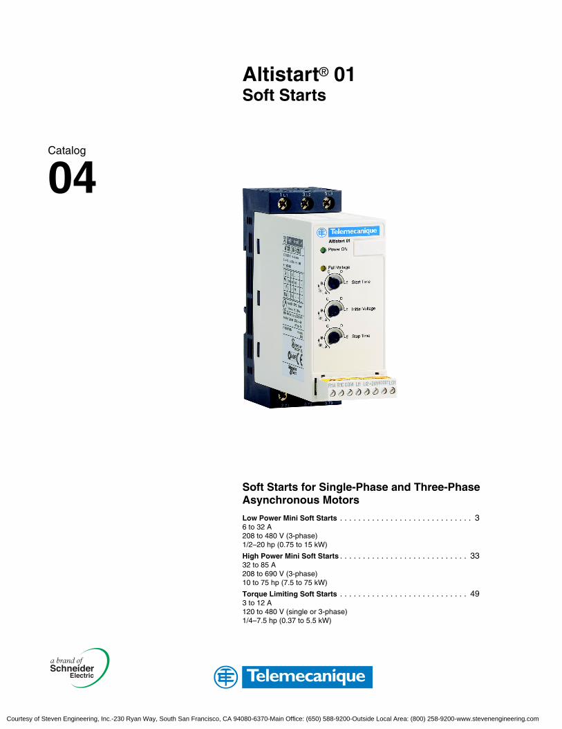
Altistart® 01Soft Starts
Soft Starts for Single-Phase and Three-Phase Asynchronous Motors
Low Power Mini Soft Starts . . . . . . . . . . . . . . . . . . . . . . . . . . . . . 36 to 32 A208 to 480 V (3-phase)1/2–20 hp (0.75 to 15 kW)
High Power Mini Soft Starts . . . . . . . . . . . . . . . . . . . . . . . . . . . . 3332 to 85 A208 to 690 V (3-phase)10 to 75 hp (7.5 to 75 kW)
Torque Limiting Soft Starts . . . . . . . . . . . . . . . . . . . . . . . . . . . . 493 to 12 A120 to 480 V (single or 3-phase)1/4–7.5 hp (0.37 to 5.5 kW)
Catalog
04
Courtesy of Steven Engineering, Inc.-230 Ryan Way, South San Francisco, CA 94080-6370-Main Office: (650) 588-9200-Outside Local Area: (800) 258-9200-www.stevenengineering.com
Product Support and Special Symbols
© 2004 Schneider Electric All Rights Reserved2
8/04
Product Support
For support and assistance, contact the Product Support Group. The Product Support Group is staffed from 8:00 am until 6:00 pm Eastern time to assist with product selection, start-up, and diagnosis of product or application problems. Emergency phone support is available 24 hours a day, 365 days a year.
Special Symbols
Throughout this catalog, the symbol “•” in a catalog number, for example ATSU01N2••LT, designates a character in the number that varies with the product rating.
Telephone 919-266-8600
Toll Free 888-Square D (888-778-2733)
E-mail [email protected]
Fax 919-217-6508
Courtesy of Steven Engineering, Inc.-230 Ryan Way, South San Francisco, CA 94080-6370-Main Office: (650) 588-9200-Outside Local Area: (800) 258-9200-www.stevenengineering.com
Low Power Mini Soft StartsOverview
38/04 © 2004 Schneider Electric All Rights Reserved
Overview
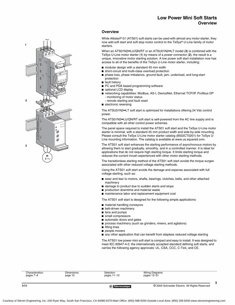
While Altistart® 01 (ATS01) soft starts can be used with almost any motor starter, they now add soft start and soft stop motor control to the TeSys® U-Line family of motor starters.
When an ATS01N2••LU/QN/RT or an ATSU01N2••LT model (3) is combined with the TeSys U-Line motor starter (1) by means of a power connector (2), the result is a unique, innovative motor starting solution. A low power soft start installation now has access to all of the benefits of the TeSys U-Line motor starter, including:
b modular design with a standard 45 mm widthb short-circuit and multi-class overload protectionb phase loss, phase imbalance, ground fault, jam, underload, and long-start
protectionb fault historyb PC and PDA based programming softwareb optional LCD displayb networking capabilities: Modbus, AS-I, DeviceNet, Ethernet TCP/IP, Profibus DP
- monitoring of motor status- remote starting and fault reset
b electronic reversing
The ATSU01N2••LT soft start is optimized for installations offering 24 Vdc control power.
The ATS01N2••LU/QN/RT soft start is self-powered from the AC line supply and is compatible with all other control power schemes.
The panel space required to install the ATS01 soft start and the TeSys U-Line motor starter is minimal, with a standard 45 mm product width and side-by-side mounting. Please consult the TeSys U-Line motor starter catalog (8502CT0201) for TeSys U-Line mounting information. The catalog is available at www.us.squared.com.
The ATS01 soft start enhances the starting performance of asynchronous motors by allowing them to start gradually, smoothly, and in a controlled manner. It is ideal for applications that do not require high starting torque. It limits starting torque and reduces the current inrush experienced with other motor starting methods.
The transitionless starting method of the ATS01 soft start avoids the torque surges associated with other reduced voltage starting methods.
Using the ATS01 soft start avoids the damage and expense associated with full voltage starting, such as:
b wear and tear to motors, shafts, bearings, clutches, belts, and other attached machinery
b damage to product due to sudden starts and stopsb production downtime and material wasteb maintenance labor and replacement equipment cost
The ATS01 soft start is designed for the following simple applications:
b material handling conveyorsb belt-driven machineryb fans and pumpsb small compressorsb automatic doors and gatesb process machinery (such as grinders, mixers, and agitators)b filling linesb people moversb any other application that can benefit from stepless reduced voltage starting
The ATS01 low power mini soft start is compact and easy to install. It was designed to meet IEC 60947-4-2, the internationally accepted standard defining soft starts, and carries the following agency approvals: UL, CSA, CCC, C-Tick, and CE.
1
2
3
Characteristics:pages 7–9
Dimensions:page 10
Selection:pages 11–12
Wiring Diagrams:pages 13–31
Courtesy of Steven Engineering, Inc.-230 Ryan Way, South San Francisco, CA 94080-6370-Main Office: (650) 588-9200-Outside Local Area: (800) 258-9200-www.stevenengineering.com
Low Power Mini Soft StartsDescription
© 2004 Schneider Electric All Rights Reserved4
8/04
Description
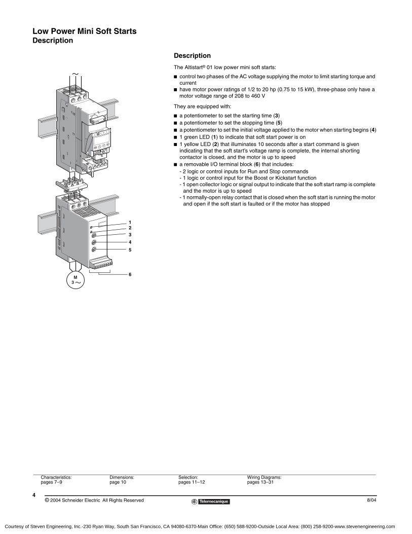
The Altistart® 01 low power mini soft starts:
b control two phases of the AC voltage supplying the motor to limit starting torque and current
b have motor power ratings of 1/2 to 20 hp (0.75 to 15 kW), three-phase only have a motor voltage range of 208 to 460 V
They are equipped with:
b a potentiometer to set the starting time (3)b a potentiometer to set the stopping time (5)b a potentiometer to set the initial voltage applied to the motor when starting begins (4)b 1 green LED (1) to indicate that soft start power is onb 1 yellow LED (2) that illuminates 10 seconds after a start command is given
indicating that the soft start’s voltage ramp is complete, the internal shorting contactor is closed, and the motor is up to speed
b a removable I/O terminal block (6) that includes:- 2 logic or control inputs for Run and Stop commands- 1 logic or control input for the Boost or Kickstart function- 1 open collector logic or signal output to indicate that the soft start ramp is complete
and the motor is up to speed- 1 normally-open relay contact that is closed when the soft start is running the motor
and open if the soft start is faulted or if the motor has stopped
123
4
5
6
Characteristics:pages 7–9
Dimensions:page 10
Selection:pages 11–12
Wiring Diagrams:pages 13–31
Courtesy of Steven Engineering, Inc.-230 Ryan Way, South San Francisco, CA 94080-6370-Main Office: (650) 588-9200-Outside Local Area: (800) 258-9200-www.stevenengineering.com
Low Power Mini Soft StartsFunctions
58/04 © 2004 Schneider Electric All Rights Reserved
Altistart® 01 soft start functions
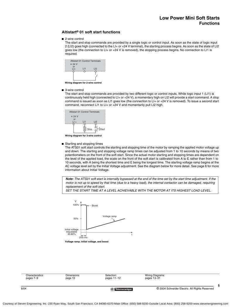
b 2-wire controlThe start and stop commands are provided by a single logic or control input. As soon as the state of logic input 2 (LI2) goes high (connected to the LI+ or +24 V terminal), the starting process begins. As soon as the state of LI2 goes low (the connection to LI+ or +24 V is removed), the stopping process begins. No connection to LI1 is required.
b 3-wire controlThe start and stop commands are provided by two different logic or control inputs. While logic input 1 (LI1) is continuously held high (connected to LI+ or +24 V), a momentary high on LI2 will provide a start command. A stop command is issued as soon as LI1 goes low (the connection to LI+ or +24 V is removed). To issue a second start command, reconnect LI1 to LI+ or +24 V and momentarily pull LI2 high.
b Starting and stopping timesThe ATS01 soft start controls the starting and stopping time of the motor by ramping the applied motor voltage up and down. The starting and stopping voltage ramp times can be adjusted from 1 to 10 seconds by means of two potentiometers on the front of the soft start. Since the actual motor starting and stopping times are dependent on the level of the applied load, the scale on the front of the soft start is calibrated from A to E rather than from 1 to 10 seconds, with A being the shortest time and E being the longest time. The starting voltage ramp begins at the AC voltage level set by the Initial Voltage adjustment. See the diagram below for more detail. See page 6 for more information about Initial Voltage.
+ 24 VorLI+ LI1 LI2
Altistart 01 Control Terminals
Wiring diagram for 2-wire control
LI1 LI2
+ 24 V or
LI +
Altistart 01 Control Terminals
Stop Start
Wiring diagram for 3-wire control
Note: The ATS01 soft start is internally bypassed at the end of the time set by the start time adjustment. If the motor is not up to speed by that time (due to a heavy load), the internal contactor can be damaged, requiring replacement of the soft start. SET THE START TIME AT A LEVEL ACHIEVABLE WITH THE MOTOR AT ITS HIGHEST LOAD LEVEL.
200 mst
100%
50%
Initial voltageAdjustable
30-80%
Voltage ramp
Boost
V
Voltage ramp, initial voltage, and boost
Characteristics:pages 7–9
Dimensions:page 10
Selection:pages 11–12
Wiring Diagrams:pages 13–31
Courtesy of Steven Engineering, Inc.-230 Ryan Way, South San Francisco, CA 94080-6370-Main Office: (650) 588-9200-Outside Local Area: (800) 258-9200-www.stevenengineering.com
Low Power Mini Soft StartsFunctions
© 2004 Schneider Electric All Rights Reserved6
8/04
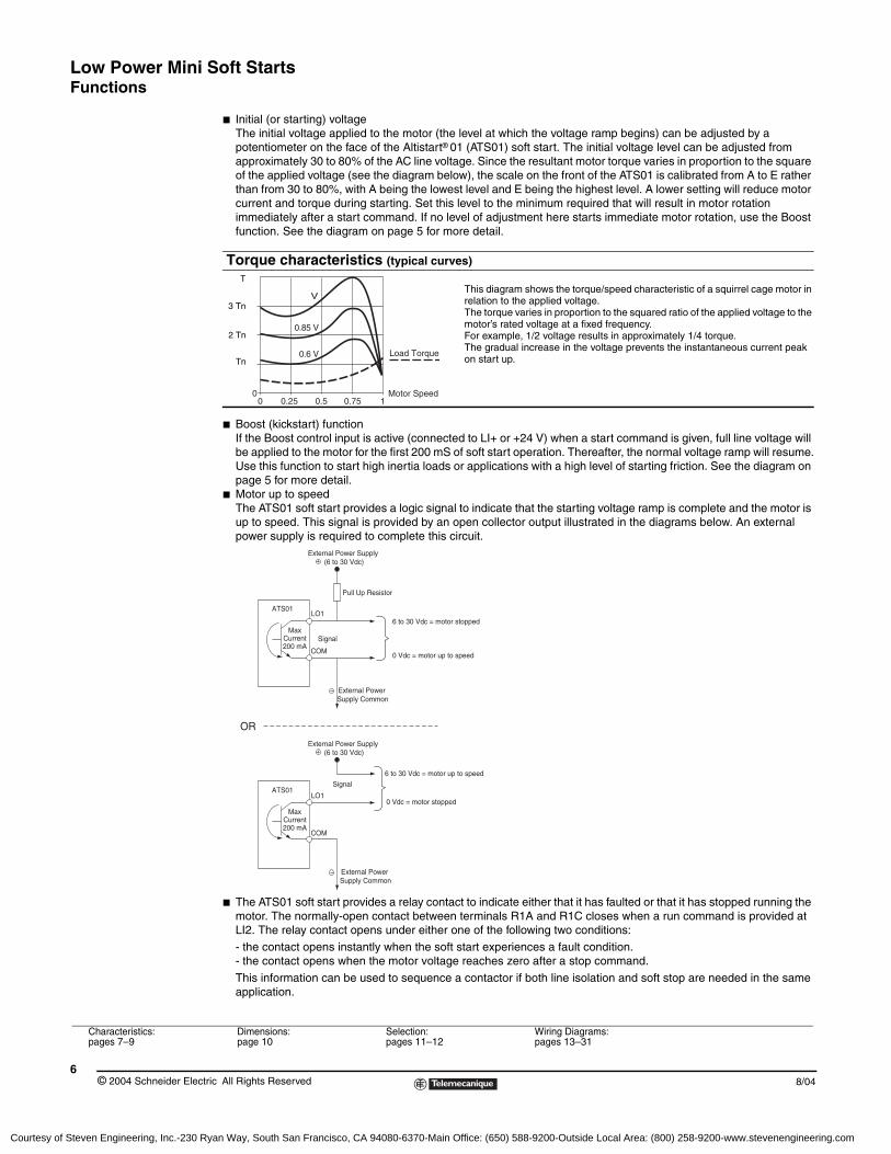
b Initial (or starting) voltageThe initial voltage applied to the motor (the level at which the voltage ramp begins) can be adjusted by a potentiometer on the face of the Altistart® 01 (ATS01) soft start. The initial voltage level can be adjusted from approximately 30 to 80% of the AC line voltage. Since the resultant motor torque varies in proportion to the square of the applied voltage (see the diagram below), the scale on the front of the ATS01 is calibrated from A to E rather than from 30 to 80%, with A being the lowest level and E being the highest level. A lower setting will reduce motor current and torque during starting. Set this level to the minimum required that will result in motor rotation immediately after a start command. If no level of adjustment here starts immediate motor rotation, use the Boost function. See the diagram on page 5 for more detail.
b Boost (kickstart) functionIf the Boost control input is active (connected to LI+ or +24 V) when a start command is given, full line voltage will be applied to the motor for the first 200 mS of soft start operation. Thereafter, the normal voltage ramp will resume.Use this function to start high inertia loads or applications with a high level of starting friction. See the diagram on page 5 for more detail.
b Motor up to speedThe ATS01 soft start provides a logic signal to indicate that the starting voltage ramp is complete and the motor is up to speed. This signal is provided by an open collector output illustrated in the diagrams below. An external power supply is required to complete this circuit.
b The ATS01 soft start provides a relay contact to indicate either that it has faulted or that it has stopped running the motor. The normally-open contact between terminals R1A and R1C closes when a run command is provided at LI2. The relay contact opens under either one of the following two conditions:
- the contact opens instantly when the soft start experiences a fault condition.- the contact opens when the motor voltage reaches zero after a stop command.
This information can be used to sequence a contactor if both line isolation and soft stop are needed in the same application.
Torque characteristics (typical curves)
This diagram shows the torque/speed characteristic of a squirrel cage motor in relation to the applied voltage. The torque varies in proportion to the squared ratio of the applied voltage to the motor’s rated voltage at a fixed frequency. For example, 1/2 voltage results in approximately 1/4 torque.The gradual increase in the voltage prevents the instantaneous current peak on start up.
00 0.25 0.5 0.75 1
Motor Speed
V
0.85 V
0.6 V Load Torque
T
3 Tn
2 Tn
Tn
Pull Up Resistor
External Power Supply (6 to 30 Vdc)
External Power Supply (6 to 30 Vdc)
MaxCurrent200 mA
LO1ATS01
Signal
Signal
6 to 30 Vdc = motor stopped
0 Vdc = motor up to speed
6 to 30 Vdc = motor up to speed
0 Vdc = motor stopped
External Power Supply Common
MaxCurrent200 mA
ATS01
External Power Supply Common
OR
COM
LO1
COM
Characteristics:pages 7–9
Dimensions:page 10
Selection:pages 11–12
Wiring Diagrams:pages 13–31
Courtesy of Steven Engineering, Inc.-230 Ryan Way, South San Francisco, CA 94080-6370-Main Office: (650) 588-9200-Outside Local Area: (800) 258-9200-www.stevenengineering.com

Low Power Mini Soft StartsCharacteristics
78/04 © 2004 Schneider Electric All Rights Reserved
EnvironmentType of starter ATS U01N2ppLT 01N2ppLU 01N2ppQN 01N2ppRTConformity to standards Altistart® 01 soft starts conform to the strictest international standards and recommendations
relating to electrical industrial control devices, in particular the standard IEC 60947-4-2.Electromagnetic compatibility EMC
CISPR 11 level B, IEC 60947-4-2, level BConducted and radiated emissionsHarmonics IEC 61000-3-2, IEC 61000-3-4EMC immunity EN 50082-2, EN 50082-1Electrostatic discharge IEC 61000-4-2 level 3Immunity to radiated radio-frequency electromagnetic field
IEC 61000-4-3 level 3
Immunity to electrical transients IEC 61000-4-4 level 4Surge immunity IEC 61000-4-5 level 3Immunity to conducted interference caused by radio-electrical fields IEC 61000-4-11
Immunity to voltage disturbances IEC 61000-4-6 level 3Damped oscillating waves IEC 61000-4-12 level 3
e marking The soft starts are e marked on the basis of European directives governing low voltage (72/73/EEC) and EMC (89/336/EEC).
Product certification UL, CSA, CCC, and C-TickDegree of protection IP20Degree of pollution 2 (conforming to IEC 60947-4-2)Vibration resistance 1.5 mm peak to peak from 3 to 13 Hz, 1 gn from 13 to 150 Hz conforming to
IEC 60068-2-6Shock resistance 15 gn for 11 ms conforming to IEC 60068-2-27Relative humidity 5–95% without condensation or dripping water, conforming to IEC 60068-2-3Ambient temperature around the unit
Storage - 25 to + 70 °C (-13 to +158 °F) conforming to IEC 60947-4-2Operation - 10 to + 40 °C (+14 to +104 °F) without derating, up to 50 °C (122 °F) with current derating of
2% per °C above 40 °C (1.1% per °F above 104 °F)Maximum operating altitude 1000 m (3300 ft) without derating
Above this, derate the current by 2.2% per additional 100 m (330ft).Side-by-side mounting No gap between soft starts is requiredOperating positionMaximum permanent angle in relation to a vertical mounting position
10˚ 10˚
Overview:pages 3–6
Dimensions:page 10
Selection:pages 11–12
Wiring Diagrams:pages 13–31
Courtesy of Steven Engineering, Inc.-230 Ryan Way, South San Francisco, CA 94080-6370-Main Office: (650) 588-9200-Outside Local Area: (800) 258-9200-www.stevenengineering.com

Low Power Mini Soft StartsCharacteristics
© 2004 Schneider Electric All Rights Reserved8
8/04
Electrical characteristicsType of starter ATS U01N2ppLT 01N2ppLU 01N2ppQN 01N2ppRTCategory of use Conforming to IEC 60947-4-2 AC-53bRated AC supply voltage 3-phase only 200–480 Vac 200–240 Vac 380–415 Vac 440–480 VacAC line voltage tolerance -15% to +10%Frequency 50 or 60 Hz ± 5% Output voltage Maximum 3-phase voltage equal to AC supply voltage.Control supply voltage 24 Vac/dc ± 10% No external control power needed.Rated operating current 6, 9, 12, 22, and 32 AAdjustable starting time 1–10 sAdjustable deceleration time 1–10 s Starting voltage 30–80% of motor’s rated voltageType of starter ATSU01N2 06LT 09LT 12LT 22LT 32LTControl power supply consumption 24 Vac/dc, 65 mA 24 Vac/dc, 100 mAPower dissipated At full load at the end of starting 1.5 W 1.5 W 1.5 W 2.5 W 2.5 W
During starting and stopping at 5 times the rated operating current
61.5 W 91.5 W 121.5 W 222.5 W 322.5 W
Type of starter ATS01N2 06LU/QN/RT 09LU/QN/RT 12LU/QN/RT 22LU/QN/RT 32LU/QN/RTPower dissipated At full load at the end of starting 4 W 4 W 4 W 4.5 W 4.5 W
During starting and stopping at 5 times the rated operating current
64 W 94 W 124 W 224.5 W 324.5 W
Type of starter ATSU01N206LT to ATSU01N222LT ATS01N206pp to ATS01N222pp
ATSU01N232LTATS01N232pp
Starting time at 5 times the rated operating current
1 s 5 s 1 s 5 s
Max. number of cycles per hour 310 20 180 10
Control Terminal Description ATSU01N2ppLT ATS01N2ppLU/QN/RT24 V and COM or LI+ and COMControl power (electrical isolation between line power and control power)
24 V ±10% from external power supplyConnect to terminals +24 V and COMMax. required current 100 mA
24 V from ATS01 internal power supplyLI+ and COMMax. available current 10 mANo short-circuit or overload protection.
LI1, LI2, Boost Logic inputsStop, Run and Boost (Kickstart) functions
27 kohms input impedance40 Vdc maximum input signalMax. current 8 mAState 0 if signal < 5 VState 1 if signal > 13 V
LO1End of starting signal
Open collector logic outputExternal power supply (minimum 6 Vdc, maximum 30 Vdc)Max current 200 mA
R1A R1CRelay outputFault signal and isolation contactor control Relay contact is open when soft start is not running or when it is faulted.
Normally-open (N.O.) contact Minimum switching capacity: 10 mA at 6 VdcMax. switching capacity on inductive load (cos ϕ = 0.5 and L/R = 20 ms):2 A at 250 Vac or 30 Vdc (AC-15)Max. operating voltage 440 Vac
LED signallingGreen LED Soft start power onYellow LED Voltage ramp complete, motor up to speed
Starting time
Full voltage status or soft start at standstill
Operating cycle t
I
ATS01 Control Terminals
ATSU01N2 LT ATS01N2 LU/QN/RT
R1A R1C COM LI1 LI2 24V BOOST LO1 R1A R1C COM LI1 LI2 LI+ BOOST LO1
Overview:pages 3–6
Dimensions:page 10
Selection:pages 11–12
Wiring Diagrams:pages 13–31
Courtesy of Steven Engineering, Inc.-230 Ryan Way, South San Francisco, CA 94080-6370-Main Office: (650) 588-9200-Outside Local Area: (800) 258-9200-www.stevenengineering.com
Low Power Mini Soft StartsCharacteristics
98/04 © 2004 Schneider Electric All Rights Reserved
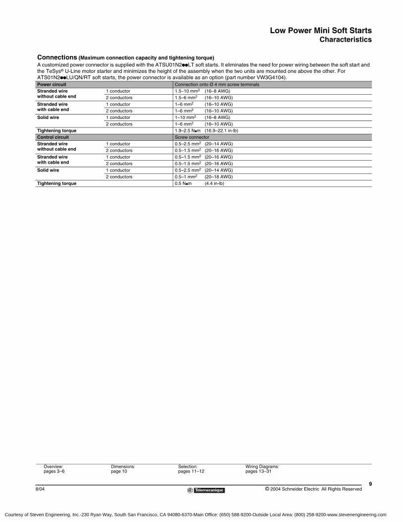
Connections (Maximum connection capacity and tightening torque)A customized power connector is supplied with the ATSU01N2ppLT soft starts. It eliminates the need for power wiring between the soft start and the TeSys® U-Line motor starter and minimizes the height of the assembly when the two units are mounted one above the other. For ATS01N2ppLU/QN/RT soft starts, the power connector is available as an option (part number VW3G4104).Power circuit Connection onto Ø 4 mm screw terminalsStranded wire without cable end
1 conductor 1.5–10 mm2 (16–8 AWG)2 conductors 1.5–6 mm2 (16–10 AWG)
Stranded wire with cable end
1 conductor 1–6 mm2 (16–10 AWG)2 conductors 1–6 mm2 (16–10 AWG)
Solid wire 1 conductor 1–10 mm2 (16–8 AWG)2 conductors 1–6 mm2 (16–10 AWG)
Tightening torque 1.9–2.5 Npm (16.9–22.1 in-lb)Control circuit Screw connectorStranded wire without cable end
1 conductor 0.5–2.5 mm2 (20–14 AWG)2 conductors 0.5–1.5 mm2 (20–16 AWG)
Stranded wire with cable end
1 conductor 0.5–1.5 mm2 (20–16 AWG)2 conductors 0.5–1.5 mm2 (20–16 AWG)
Solid wire 1 conductor 0.5–2.5 mm2 (20–14 AWG)2 conductors 0.5–1 mm2 (20–18 AWG)
Tightening torque 0.5 Npm (4.4 in-lb)
Overview:pages 3–6
Dimensions:page 10
Selection:pages 11–12
Wiring Diagrams:pages 13–31
Courtesy of Steven Engineering, Inc.-230 Ryan Way, South San Francisco, CA 94080-6370-Main Office: (650) 588-9200-Outside Local Area: (800) 258-9200-www.stevenengineering.com
Low Power Mini Soft StartsDimensions
© 2004 Schneider Electric All Rights Reserved10
8/04
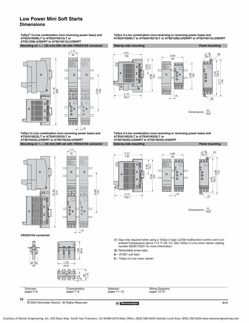
TeSys® U-Line combination (non-reversing power base) and ATSU01N206LT to ATSU01N212LT or ATS01206LU/QN/RT to ATS01N212LU/QN/RT
TeSys U-Line combination (non-reversing or reversing power base) and ATSU01N206LT to ATSU01N212LT or ATS01206LU/QN/RT to ATS01N212LU/QN/RT
Mounting on 5 (35 mm) DIN rail with VW3G4104 connector Side-by-side mounting Panel mounting
TeSys U-Line combination (non-reversing power base) and ATSU01N222LT to ATSU01N232LT orATS01N222LU/QN/RT to ATS01N232LU/QN/RT
TeSys U-Line combination (non-reversing or reversing power base) and ATSU01N222LT to ATSU01N232LT orATS01N222LU/QN/RT to ATS01N232LU/QN/RT
Mounting on 5 (35 mm) DIN rail with VW3G4104 connector Side-by-side mounting Panel mounting
VW3G4104 connector
(1) Gap only required when using a TeSys U type LUCM multifunction control unit in an ambient temperature above 113 °F (45 °C). See TeSys U-Line motor starter catalog number 8502CT0201 for more information.
(2) Retractable screw tabs.A – ATS01 soft start.U – TeSys U-Line motor starter.
5.9
11
50
11
.18
28
4
1.7745
U U
A A
U
A
(1)
3.9099
5.31135
5.15130.7
6.06
154
2.84
72.2
4.88
124A A
U
U
(1)(2)
(2)1.1930.2
5.71
145
5.22
132.
5
in.mm
Dimensions:
12.3
63
14
1.7745
6.6
91
70
U U U
A AA
(1)
3.9099
5.31135
2.84
72.2
6.06
154A U A
1.1930.2
6.40
162.
56.
8917
5
5.15130.7
(1)(1)
(1)
in.mm
Dimensions:
1.7644.8
0.7920
0.24 6
1.83
46.6
28 1.10
Overview:pages 3–6
Characteristics:pages 7–9
Selection:pages 11–12
Wiring Diagrams:pages 13–31
Courtesy of Steven Engineering, Inc.-230 Ryan Way, South San Francisco, CA 94080-6370-Main Office: (650) 588-9200-Outside Local Area: (800) 258-9200-www.stevenengineering.com
Low Power Mini Soft StartsSelection
118/04 © 2004 Schneider Electric All Rights Reserved
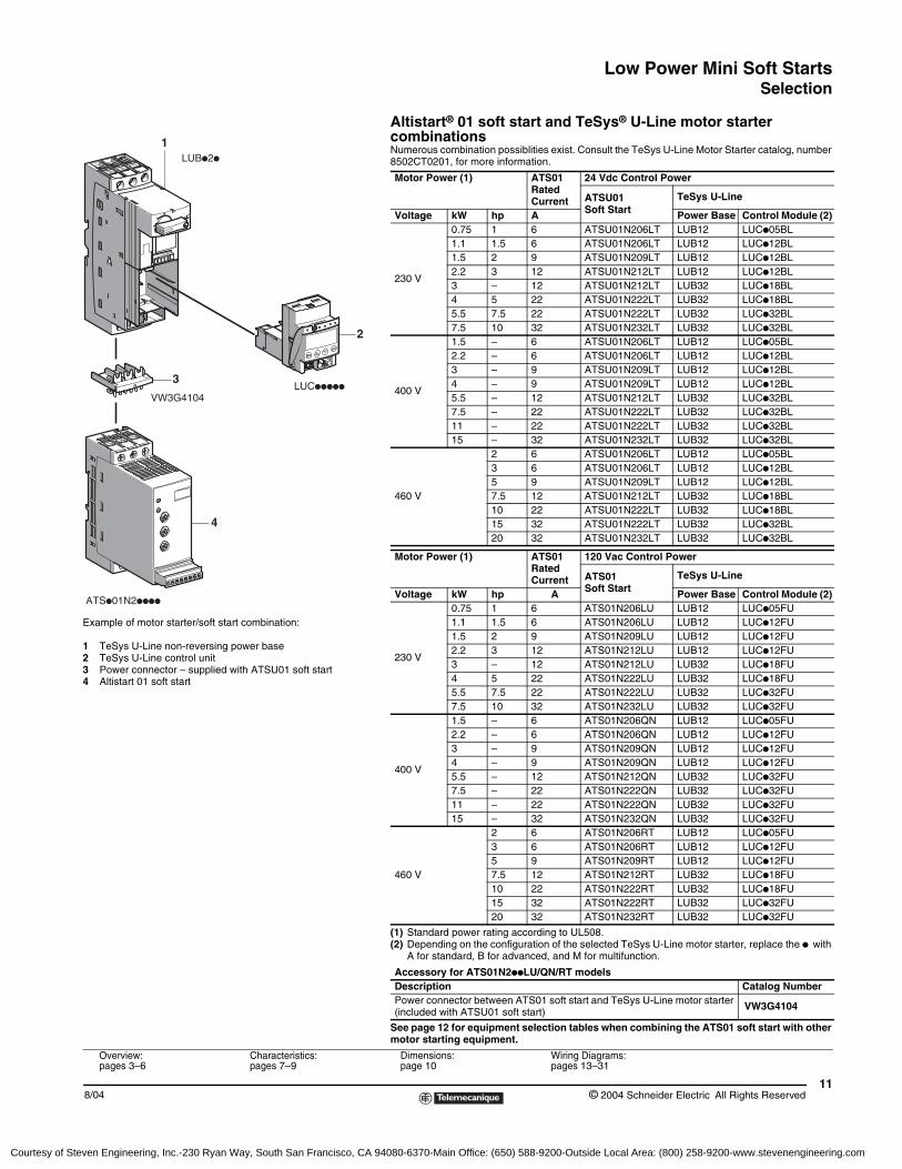
Altistart® 01 soft start and TeSys® U-Line motor starter combinationsNumerous combination possiblities exist. Consult the TeSys U-Line Motor Starter catalog, number 8502CT0201, for more information.
(1) Standard power rating according to UL508.(2) Depending on the configuration of the selected TeSys U-Line motor starter, replace the p with
A for standard, B for advanced, and M for multifunction.
See page 12 for equipment selection tables when combining the ATS01 soft start with other motor starting equipment.
Motor Power (1) ATS01 Rated Current
24 Vdc Control Power
ATSU01Soft Start
TeSys U-Line
Voltage kW hp A Power Base Control Module (2)
230 V
0.75 1 6 ATSU01N206LT LUB12 LUCp05BL1.1 1.5 6 ATSU01N206LT LUB12 LUCp12BL1.5 2 9 ATSU01N209LT LUB12 LUCp12BL2.2 3 12 ATSU01N212LT LUB12 LUCp12BL3 – 12 ATSU01N212LT LUB32 LUCp18BL4 5 22 ATSU01N222LT LUB32 LUCp18BL5.5 7.5 22 ATSU01N222LT LUB32 LUCp32BL7.5 10 32 ATSU01N232LT LUB32 LUCp32BL
400 V
1.5 – 6 ATSU01N206LT LUB12 LUCp05BL2.2 – 6 ATSU01N206LT LUB12 LUCp12BL3 – 9 ATSU01N209LT LUB12 LUCp12BL4 – 9 ATSU01N209LT LUB12 LUCp12BL5.5 – 12 ATSU01N212LT LUB32 LUCp32BL7.5 – 22 ATSU01N222LT LUB32 LUCp32BL11 – 22 ATSU01N222LT LUB32 LUCp32BL15 – 32 ATSU01N232LT LUB32 LUCp32BL
460 V
2 6 ATSU01N206LT LUB12 LUCp05BL3 6 ATSU01N206LT LUB12 LUCp12BL5 9 ATSU01N209LT LUB12 LUCp12BL7.5 12 ATSU01N212LT LUB32 LUCp18BL10 22 ATSU01N222LT LUB32 LUCp18BL15 32 ATSU01N222LT LUB32 LUCp32BL20 32 ATSU01N232LT LUB32 LUCp32BL
Motor Power (1) ATS01 Rated Current
120 Vac Control Power
ATS01 Soft Start
TeSys U-Line
Voltage kW hp A Power Base Control Module (2)
230 V
0.75 1 6 ATS01N206LU LUB12 LUCp05FU1.1 1.5 6 ATS01N206LU LUB12 LUCp12FU1.5 2 9 ATS01N209LU LUB12 LUCp12FU2.2 3 12 ATS01N212LU LUB12 LUCp12FU3 – 12 ATS01N212LU LUB32 LUCp18FU4 5 22 ATS01N222LU LUB32 LUCp18FU5.5 7.5 22 ATS01N222LU LUB32 LUCp32FU7.5 10 32 ATS01N232LU LUB32 LUCp32FU
400 V
1.5 – 6 ATS01N206QN LUB12 LUCp05FU2.2 – 6 ATS01N206QN LUB12 LUCp12FU3 – 9 ATS01N209QN LUB12 LUCp12FU4 – 9 ATS01N209QN LUB12 LUCp12FU5.5 – 12 ATS01N212QN LUB32 LUCp32FU7.5 – 22 ATS01N222QN LUB32 LUCp32FU11 – 22 ATS01N222QN LUB32 LUCp32FU15 – 32 ATS01N232QN LUB32 LUCp32FU
460 V
2 6 ATS01N206RT LUB12 LUCp05FU3 6 ATS01N206RT LUB12 LUCp12FU5 9 ATS01N209RT LUB12 LUCp12FU7.5 12 ATS01N212RT LUB32 LUCp18FU10 22 ATS01N222RT LUB32 LUCp18FU15 32 ATS01N222RT LUB32 LUCp32FU20 32 ATS01N232RT LUB32 LUCp32FU
Accessory for ATS01N2ppLU/QN/RT modelsDescription Catalog NumberPower connector between ATS01 soft start and TeSys U-Line motor starter (included with ATSU01 soft start) VW3G4104
1
2
4
LUBp2p
LUCppppp
ATSp01N2pppp
3
VW3G4104
Example of motor starter/soft start combination:
1 TeSys U-Line non-reversing power base2 TeSys U-Line control unit3 Power connector – supplied with ATSU01 soft start4 Altistart 01 soft start
Overview:pages 3–6
Characteristics:pages 7–9
Dimensions:page 10
Wiring Diagrams:pages 13–31
Courtesy of Steven Engineering, Inc.-230 Ryan Way, South San Francisco, CA 94080-6370-Main Office: (650) 588-9200-Outside Local Area: (800) 258-9200-www.stevenengineering.com

Low Power Mini Soft StartsSelection
© 2004 Schneider Electric All Rights Reserved12
8/04
(1) Fuses are not required when using the GV manual starter with motor branch-circuit protection installed per NEC article 430.(2) The overload relay is not required when using the GV manual starter.
Altistart® 01 soft start combinations with other Telemecanique motor starting equipment
MotorATS01
Soft StartGV Manual
StarterKM1 Isolation
Contactor
Fast-acting Class J
Fuses (1)Overload Relay (2)hp
200/208 V 230/240 V1/2 1/2 ATS01N206LU GV2ME07 LC1D09 or LC1K06 10 A LRD07 or LR2K0308
3/4 ATS01N206LU GV2ME08 LC1D09 or LC1K06 10 A LRD08 or LR2K03103/4 ATS01N206LU GV2ME08 LC1D09 or LC1K06 15 A LRD08 or LR2K03101 1 ATS01N206LU GV2ME10 LC1D09 or LC1K06 15 A LRD10 or LR2K0312
1.5 ATS01N206LU GV2ME10 LC1D09 or LC1K06 20 A LRD12 or LR2K03142 ATS01N209LU GV2ME14 LC1D09 or LC1K09 20 A LRD12 or LR2K0314
1.5–2 ATS01N209LU GV2ME14 LC1D09 or LC1K09 25 A LRD12 or LR2K03143 ATS01N212LU GV2ME16 LC1D12 or LC1K12 30 A LRD16 or LR2K0316
3 ATS01N212LU GV2ME16 LC1D12 or LC1K12 35 A LRD16 or LR2K03165 ATS01N222LU GV2ME20 LC1D18 50 A LRD21
5 ATS01N222LU GV2ME20 LC1D18 60 A LRD227.5 ATS01N222LU GV2ME21 LC1D25 70 A LRD22
7.5 ATS01N232LU GV2ME32 LC1D25 80 A LRD3210 ATS01N232LU GV2ME32 LC1D32 90 A LRD32
10 ATS01N232LU GV2ME32 LC1D32 100 A LRD35
MotorATS01
Soft StartGV Manual
StarterKM1 Isolation
Contactor
Fast-acting Class J
Fuses (1)Overload Relay (2)kW
400 V1.1 ATS01N206QN GV2ME07 LC1D09 or LC1K06 10 A LRD07 or LR2K03081.5 ATS01N206QN GV2ME08 LC1D09 or LC1K06 15 A LRD08 or LR2K03102.2 ATS01N206QN GV2ME10 LC1D09 or LC1K06 15 A LRD10 or LR2K03123 ATS01N209QN GV2ME14 LC1D09 or LC1K09 20 A LRD12 or LR2K03144 ATS01N209QN GV2ME14 LC1D09 or LC1K09 25 A LRD14 or LR2K0316
5.5 ATS01N212QN GV2ME16 LC1D12 or LC1K12 35 A LRD16 or LR2K03167.5 ATS01N222QN GV2ME20 LC1D18 45 A LRD219 ATS01N222QN GV2ME21 LC1D25 60 A LRD2211 ATS01N222QN GV2ME21 LC1D25 70 A LRD2215 ATS01N232QN GV2ME32 LC1D32 90 A LRD32
MotorATS01
Soft StartGV Manual
StarterKM1 Isolation
Contactor
Fast-acting Class J
Fuses (1)Overload Relay (2)hp
460 V1/2 ATS01N206RT GV2ME06 LC1D09 or LC1K06 3 A LRD06 or LR2K03063/4 ATS01N206RT GV2ME06 LC1D09 or LC1K06 6 A LRD06 or LR2K03071 ATS01N206RT GV2ME07 LC1D09 or LC1K06 6 A LRD07 or LR2K0308
1.5–2 ATS01N206RT GV2ME08 LC1D09 or LC1K06 10 A LRD08 or LR2K03103 ATS01N206RT GV2ME10 LC1D09 or LC1K06 15 A LRD10 or LR2K03125 ATS01N209RT GV2ME14 LC1D09 or LC1K09 25 A LRD12 or LR2K0314
7.5 ATS01N212RT GV2ME16 LC1D12 or LC1K12 35 A LRD16 or LR2K031610 ATS01N222RT GV2ME20 LC1D18 45 A LRD2115 ATS01N222RT GV2ME21 LC1D25 70 A LRD2220 ATS01N232RT GV2ME32 LC1D32 90 A LRD32
Overview:pages 3–6
Characteristics:pages 7–9
Dimensions:page 10
Wiring Diagrams:pages 13–31
Courtesy of Steven Engineering, Inc.-230 Ryan Way, South San Francisco, CA 94080-6370-Main Office: (650) 588-9200-Outside Local Area: (800) 258-9200-www.stevenengineering.com
Low Power Mini Soft StartsWiring Diagrams
138/04 © 2004 Schneider Electric All Rights Reserved
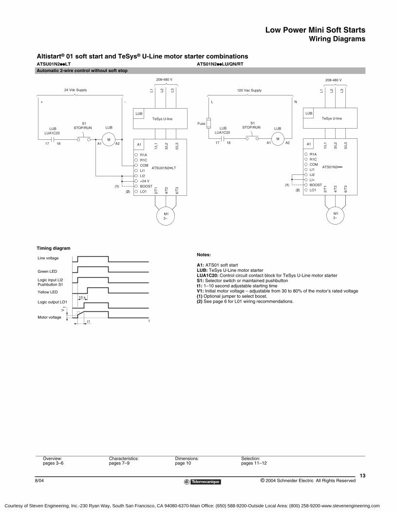
Altistart® 01 soft start and TeSys® U-Line motor starter combinationsATSU01N2ppLT ATS01N2ppLU/QN/RTAutomatic 2-wire control without soft stop
Timing diagramNotes:
A1: ATS01 soft startLUB: TeSys U-Line motor starterLUA1C20: Control circuit contact block for TeSys U-Line motor starterS1: Selector switch or maintained pushbuttont1: 1–10 second adjustable starting timeV1: Initial motor voltage – adjustable from 30 to 80% of the motor’s rated voltage(1) Optional jumper to select boost.(2) See page 6 for L01 wiring recommendations.
STOP/RUN
1817
LUBLUA1C20
+
S1
24 Vdc Supply
3~
ATSU01N2••LT
BOOST
2/T
1(1)
(2) LO1
LI1
+24 V
LI2
COM
A1
R1A
R1C1/
L1
4/T
2
6/T
3
M1
3/L2
5/L3A1 A2
TeSys U-line
L1 L2
LUB
L3
M
LUB
-
208-480 V
ATS01N2••••
3~
BOOST
2/T
1(1)
(2) LO1
LI1
LI2
COM
LI+
A1
R1A
R1C
1/L1
6/T
3
4/T
2
M1
5/L3
3/L2
A2A11817
STOP/RUN
120 Vac Supply
FuseLUB
LUA1C20
L
TeSys U-line
L1 L2
LUB
L3
208-480 V
S1
M
LUB
N
10 s
tt1
V1
Line voltage
Green LED
Logic input LI2Pushbutton S1
Logic output LO1
Yellow LED
Motor voltage
Overview:pages 3–6
Characteristics:pages 7–9
Dimensions:page 10
Selection:pages 11–12
Courtesy of Steven Engineering, Inc.-230 Ryan Way, South San Francisco, CA 94080-6370-Main Office: (650) 588-9200-Outside Local Area: (800) 258-9200-www.stevenengineering.com
Low Power Mini Soft StartsWiring Diagrams
© 2004 Schneider Electric All Rights Reserved14
8/04
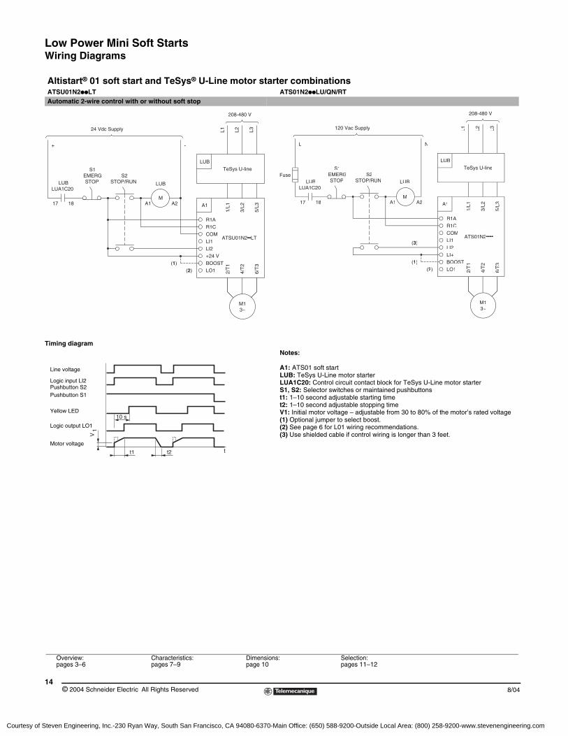
Altistart® 01 soft start and TeSys® U-Line motor starter combinationsATSU01N2ppLT ATS01N2ppLU/QN/RTAutomatic 2-wire control with or without soft stop
Timing diagramNotes:
A1: ATS01 soft startLUB: TeSys U-Line motor starterLUA1C20: Control circuit contact block for TeSys U-Line motor starterS1, S2: Selector switches or maintained pushbuttonst1: 1–10 second adjustable starting timet2: 1–10 second adjustable stopping timeV1: Initial motor voltage – adjustable from 30 to 80% of the motor’s rated voltage(1) Optional jumper to select boost.(2) See page 6 for L01 wiring recommendations.(3) Use shielded cable if control wiring is longer than 3 feet.
TeSys U-line
L1 L2
LUB
LUB
L3
STOP/RUNLUA1C20
LUB
17 18
EMERGSTOP
S1S2
3~
ATSU01N2••LT
BOOST
2/T
1(1)(2) LO1
LI1
+24 VLI2
COM
A1
R1AR1C
1/L1
4/T
2
6/T
3
M1
3/L2
5/L3
A1M
A2
+
24 Vdc Supply
-
208-480 V
TeSys U-line
L1 L2
LUB
LUB
L3
STOP/RUNFuse
LUA1C20
1817
LUB STOP
S1EMERG
ATS01N2••••
3~
BOOST
2/T
1(1)(2) LO1
LI1LI2
COM
LI+
A1
R1AR1C
1/L1
6/T
3
4/T
2
M1
5/L3
3/L2
A1 A2M
S2
120 Vac Supply
L
208-480 V
N
(3)
t2 tt1
10 s
V1
Line voltage
Logic input LI2Pushbutton S2
Logic output LO1
Yellow LED
Motor voltage
Pushbutton S1
Overview:pages 3–6
Characteristics:pages 7–9
Dimensions:page 10
Selection:pages 11–12
Courtesy of Steven Engineering, Inc.-230 Ryan Way, South San Francisco, CA 94080-6370-Main Office: (650) 588-9200-Outside Local Area: (800) 258-9200-www.stevenengineering.com
Low Power Mini Soft StartsWiring Diagrams
158/04 © 2004 Schneider Electric All Rights Reserved
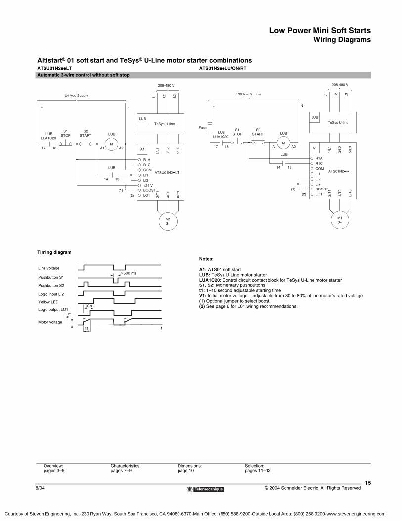
Altistart® 01 soft start and TeSys® U-Line motor starter combinationsATSU01N2ppLT ATS01N2ppLU/QN/RTAutomatic 3-wire control without soft stop
Timing diagramNotes:
A1: ATS01 soft startLUB: TeSys U-Line motor starterLUA1C20: Control circuit contact block for TeSys U-Line motor starterS1, S2: Momentary pushbuttonst1: 1–10 second adjustable starting timeV1: Initial motor voltage – adjustable from 30 to 80% of the motor’s rated voltage(1) Optional jumper to select boost.(2) See page 6 for L01 wiring recommendations.
STARTLUA1C20
LUB
LUB
17
STOPS1
18
S2
+
24 Vdc Supply
3~
ATSU01N2••LT
BOOST
2/T
1(1)(2) LO1
LI1
+24 VLI2
COM
A1
R1AR1C
1/L1
4/T
2
6/T
3
M1
3/L2
5/L3
1314
TeSys U-line
L1 L2
LUB
LUB
L3
A1M
A2
-
208-480 V
120 Vac Supply
Fuse
18
LUBLUA1C20
17
STOPS1
L
ATS01N2••••
3~
BOOST
2/T
1(1)(2) LO1
LI1LI2
COM
LI+
A1
R1AR1C
1/L1
6/T
3
4/T
2
M1
5/L3
3/L2
TeSys U-line
L1 L2
LUB
L3
208-480 V
LUB
14 13
A1
STARTS2
A2
LUB
M
N
500 ms
tt1
10 s
V1
Line voltage
Pushbutton S1
Logic output LO1
Yellow LED
Motor voltage
Logic input LI2
Pushbutton S2
Overview:pages 3–6
Characteristics:pages 7–9
Dimensions:page 10
Selection:pages 11–12
Courtesy of Steven Engineering, Inc.-230 Ryan Way, South San Francisco, CA 94080-6370-Main Office: (650) 588-9200-Outside Local Area: (800) 258-9200-www.stevenengineering.com

Low Power Mini Soft StartsWiring Diagrams
© 2004 Schneider Electric All Rights Reserved16
8/04
Altistart® 01 soft start and TeSys® U-Line motor starter combinationsATSU01N2ppLT ATS01N2ppLU/QN/RTAutomatic 3-wire control with soft stop
Timing diagramNotes:
A1: ATS01 soft startLUB: TeSys U-Line motor starterLUA1C20: Control circuit contact block for TeSys U-Line motor starterS1, S2: Momentary pushbuttonst1: 1–10 second adjustable starting timet2: 1–10 second adjustable stopping timeV1: Initial motor voltage – adjustable from 30 to 80% of the motor’s rated voltage(1) Optional jumper to select boost.(2) See page 6 for L01 wiring recommendations.(3) Use shielded cable if control wiring is longer than 3 feet.
Overview:pages 3–6
Characteristics:pages 7–9
Dimensions:page 10
Selection:pages 11–12
START
1817
S1STOP
24 Vdc Supply
LUA1C20LUB
+
S2
TeSys U-line
L1 L2
LUB
L3
M
LUB
3~
ATSU01N2••LT
BOOST
2/T
1(1)(2) LO1
LI1
+24 VLI2
COM
A1
R1AR1C
1/L1
4/T
2
6/T
3
M1
3/L2
5/L3
1314
A1
LUB
A2
-
208-480 V
120 Vac Supply
S1STOP
1817
FuseLUB
LUA1C20
L
TeSys U-line
L1 L2 L3
M
ATS01N2••••
3~
BOOST
2/T
1
(1)
(3)
(2) LO1
LI1LI2
COM
LI+
A1
R1AR1C
1/L1
6/T
3
4/T
2
M1
5/L3
3/L2
14 13
A1 A2
LUB
LUB
LUB
208-480 V
S2START
N
t
10 s
t1 t2
V1
Line voltage
Logic output LO1
Yellow LED
Motor voltage
Logic input LI2Pushbutton S2Logic input LI1Pushbutton S1
Courtesy of Steven Engineering, Inc.-230 Ryan Way, South San Francisco, CA 94080-6370-Main Office: (650) 588-9200-Outside Local Area: (800) 258-9200-www.stevenengineering.com
Low Power Mini Soft StartsWiring Diagrams
178/04 © 2004 Schneider Electric All Rights Reserved
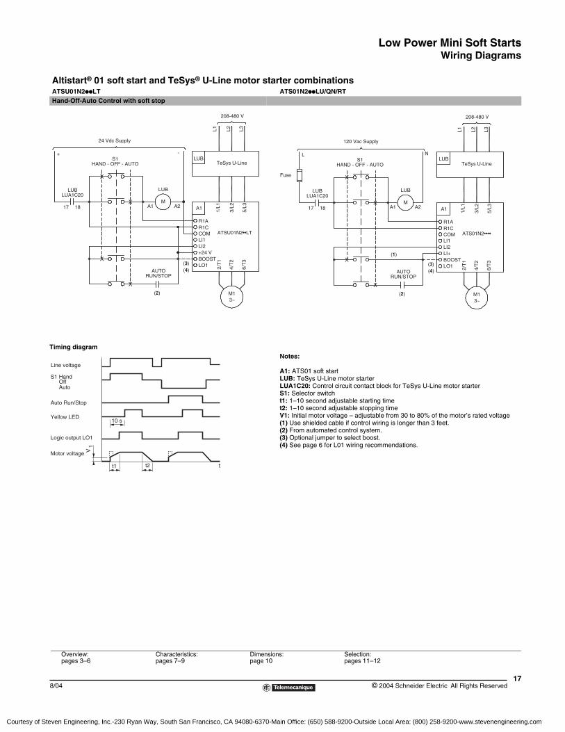
Altistart® 01 soft start and TeSys® U-Line motor starter combinationsATSU01N2ppLT ATS01N2ppLU/QN/RTHand-Off-Auto Control with soft stop
Timing diagramNotes:
A1: ATS01 soft startLUB: TeSys U-Line motor starterLUA1C20: Control circuit contact block for TeSys U-Line motor starterS1: Selector switcht1: 1–10 second adjustable starting timet2: 1–10 second adjustable stopping timeV1: Initial motor voltage – adjustable from 30 to 80% of the motor’s rated voltage(1) Use shielded cable if control wiring is longer than 3 feet.(2) From automated control system.(3) Optional jumper to select boost.(4) See page 6 for L01 wiring recommendations.
Overview:pages 3–6
Characteristics:pages 7–9
Dimensions:page 10
Selection:pages 11–12
24 Vdc Supply
208-480 V
+S1
HAND - OFF - AUTO
LUBLUA1C20
17 18 A1 A2M
LUB
LUBTeSys U-Line
L1 L2 L3
1/L1
3/L2
5/L3A1
R1AR1CCOMLI1LI2+24 V
LO1BOOST
2/T
1
4/T
2
6/T
3
M13~
(3)
AUTORUN/STOP
-
(2)
(4)
ATSU01N2••LT
120 Vac Supply
208-480 V
LS1
HAND - OFF - AUTO
LUBLUA1C20
17 18 A1 A2M
LUB
LUBTeSys U-Line
L1 L2 L3
1/L1
3/L2
5/L3A1
R1AR1CCOMLI1LI2LI+
LO1BOOST
2/T
1
4/T
2
6/T
3
M13~
(3)
AUTORUN/STOP
N
(1)
(2)
(4)
ATS01N2••••
Fuse
tt1 t2
10 s
Motor voltage
Logic output LO1
Yellow LED
Auto Run/Stop
S1 HandOffAuto
Line voltage
V1
Courtesy of Steven Engineering, Inc.-230 Ryan Way, South San Francisco, CA 94080-6370-Main Office: (650) 588-9200-Outside Local Area: (800) 258-9200-www.stevenengineering.com
Low Power Mini Soft StartsWiring Diagrams
© 2004 Schneider Electric All Rights Reserved18
8/04
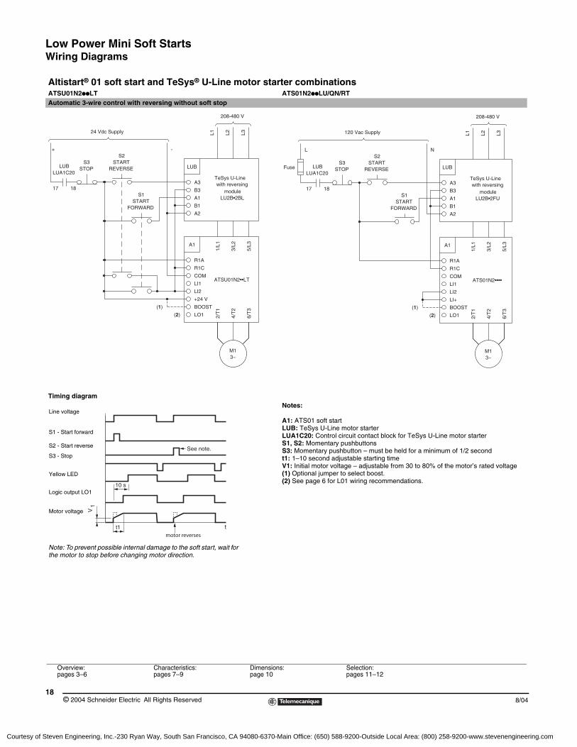
Altistart® 01 soft start and TeSys® U-Line motor starter combinationsATSU01N2ppLT ATS01N2ppLU/QN/RTAutomatic 3-wire control with reversing without soft stop
Timing diagramNotes:
A1: ATS01 soft startLUB: TeSys U-Line motor starterLUA1C20: Control circuit contact block for TeSys U-Line motor starterS1, S2: Momentary pushbuttonsS3: Momentary pushbutton – must be held for a minimum of 1/2 secondt1: 1–10 second adjustable starting timeV1: Initial motor voltage – adjustable from 30 to 80% of the motor’s rated voltage(1) Optional jumper to select boost.(2) See page 6 for L01 wiring recommendations.
Overview:pages 3–6
Characteristics:pages 7–9
Dimensions:page 10
Selection:pages 11–12
STOPS3
24 Vdc Supply
LUA1C20
17 18
LUB
+
LUB
A2
moduleLU2B•2BL
with reversingTeSys U-Line
A3
B1
A1
B3
L1 L2 L3
3~
ATSU01N2••LT
BOOST
2/T
1(1)
(2) LO1
LI1
+24 V
LI2
COM
A1
R1A
R1C
1/L1
4/T
2
6/T
3
M1
3/L2
5/L3
208-480 V
FORWARDSTART
S1
REVERSESTART
S2-
ATS01N2••••
3~
BOOST
2/T
1(1)
(2) LO1
LI1
LI2
COM
LI+
A1
R1A
R1C
1/L1
6/T
3
4/T
2
M1
5/L3
3/L2
A2
LUA1C20
17 18
Fuse LUB
L
B3
A1
B1
A3
STARTFORWARD
STOPS3
S2
REVERSESTART
S1
LUB
N
120 Vac Supply
TeSys U-Linewith reversing
LU2B•2FUmodule
208-480 V
L2L1 L3
tt1
10 s
motor reverses
See note.
V1
Line voltage
Logic output LO1
Yellow LED
Motor voltage
S3 - Stop
S2 - Start reverse
S1 - Start forward
Note: To prevent possible internal damage to the soft start, wait for the motor to stop before changing motor direction.
Courtesy of Steven Engineering, Inc.-230 Ryan Way, South San Francisco, CA 94080-6370-Main Office: (650) 588-9200-Outside Local Area: (800) 258-9200-www.stevenengineering.com
Low Power Mini Soft StartsWiring Diagrams
198/04 © 2004 Schneider Electric All Rights Reserved
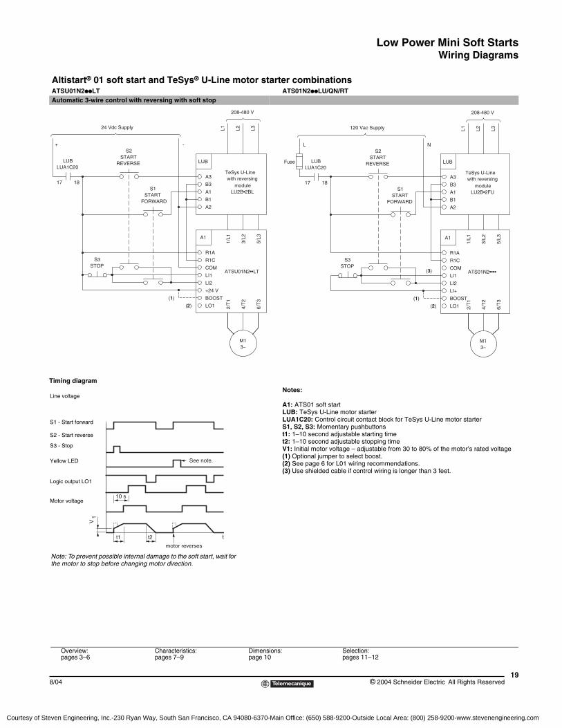
Altistart® 01 soft start and TeSys® U-Line motor starter combinationsATSU01N2ppLT ATS01N2ppLU/QN/RTAutomatic 3-wire control with reversing with soft stop
Timing diagramNotes:
A1: ATS01 soft startLUB: TeSys U-Line motor starterLUA1C20: Control circuit contact block for TeSys U-Line motor starterS1, S2, S3: Momentary pushbuttonst1: 1–10 second adjustable starting timet2: 1–10 second adjustable stopping timeV1: Initial motor voltage – adjustable from 30 to 80% of the motor’s rated voltage(1) Optional jumper to select boost.(2) See page 6 for L01 wiring recommendations.(3) Use shielded cable if control wiring is longer than 3 feet.
Overview:pages 3–6
Characteristics:pages 7–9
Dimensions:page 10
Selection:pages 11–12
LUB
A2
moduleLU2B•2BL
with reversingTeSys U-Line
A3
B1
A1
B3
L1 L2 L3
STOPS3
LUBLUA1C20
17 18
3~
ATSU01N2••LT
BOOST
2/T
1(1)
(2) LO1
LI1
+24 V
LI2
COM
A1
R1A
R1C
1/L1
4/T
2
6/T
3
M1
3/L2
5/L3
FORWARD
S1START
REVERSESTART
24 Vdc Supply
+
208-480 V
S2-
Fuse LUB
18
LUA1C20
17
ATS01N2••••
3~
BOOST
2/T
1(1)
(3)
(2) LO1
LI1
LI2
COM
LI+
A1
R1A
R1C
1/L1
6/T
3
4/T
2
M1
5/L3
3/L2
B3
A1
B1
A3
A2
S3STOP
STARTFORWARD
STARTREVERSE
S1
LUB
LU2B•2FU
TeSys U-Linewith reversing
module
L
120 Vac Supply
S2N
L2L1 L3
208-480 V
tt1 t2
10 s
motor reverses
See note.
V1
Line voltage
Logic output LO1
Yellow LED
Motor voltage
S3 - Stop
S2 - Start reverse
S1 - Start forward
Note: To prevent possible internal damage to the soft start, wait for the motor to stop before changing motor direction.
Courtesy of Steven Engineering, Inc.-230 Ryan Way, South San Francisco, CA 94080-6370-Main Office: (650) 588-9200-Outside Local Area: (800) 258-9200-www.stevenengineering.com
Low Power Mini Soft StartsWiring Diagrams
© 2004 Schneider Electric All Rights Reserved20
8/04
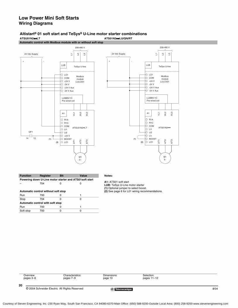
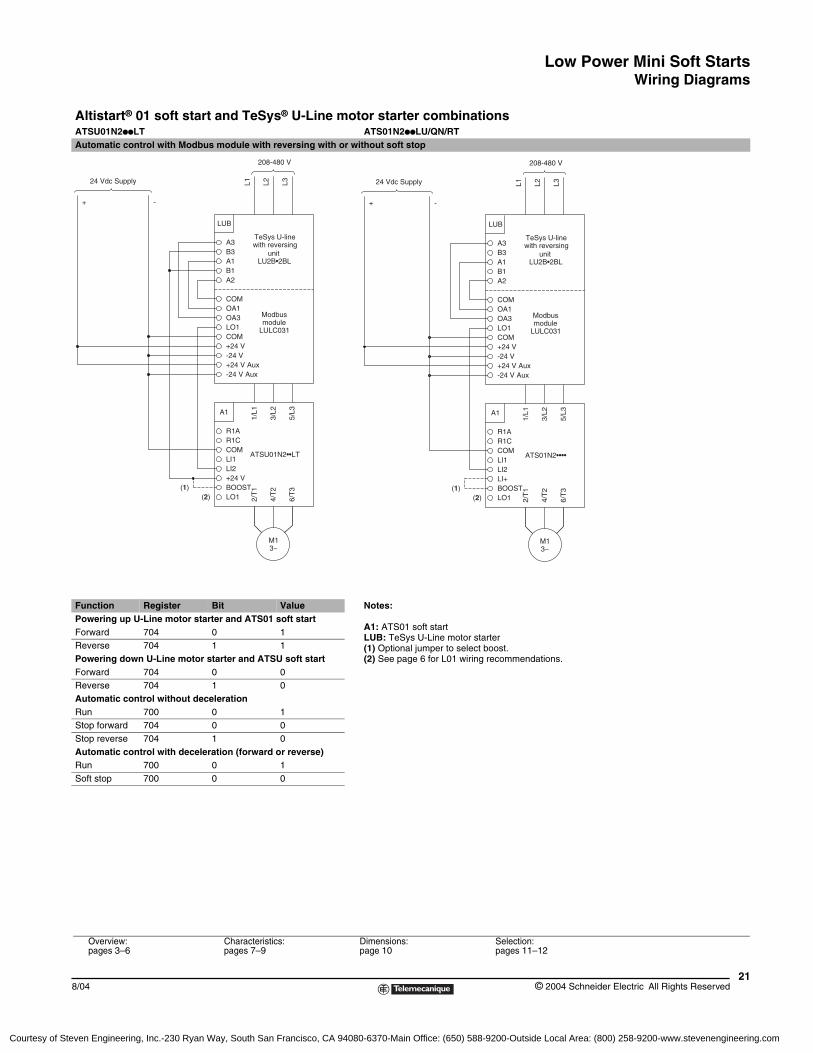
Altistart® 01 soft start and TeSys® U-Line motor starter combinationsATSU01N2ppLT ATS01N2ppLU/QN/RTAutomatic control with Modbus module with or without soft stop
Function Register Bit Value Notes:
A1: ATS01 soft startLUB: TeSys U-Line motor starter(1) Optional jumper to select boost.(2) See page 6 for L01 wiring recommendations.
Powering down U-Line motor starter and ATS01soft start– 704 0 0
Automatic control without soft stopRun 700 0 1Stop 704 0 0Automatic control with soft stopRun 700 0 1Soft stop 700 0 0
Overview:pages 3–6
Characteristics:pages 7–9
Dimensions:page 10
Selection:pages 11–12
24 Vdc Supply
1314
QF1
+
LU9BN11CPre-wired coil
LUB
LO1
-24 V Aux
moduleModbus
+24 V Aux
LULC031
COM
+24 V
-24 V
TeSys U-line
L1 L3L2
3~
ATSU01N2••LT
BOOST
2/T
1(1)
(2) LO1
LI1
+24 V
LI2
COM
A1
R1A
R1C
1/L1
4/T
2
6/T
3
M1
3/L2
5/L3
208-480 V
-
24 Vdc Supply
+
LU9BN11CPre-wired coil
LUB
LO1
-24 V Aux
moduleModbus
+24 V Aux
LULC031
COM
+24 V
-24 V
TeSys U-line
L1 L3L2
ATS01N2••••
3~
BOOST
2/T
1(1)
(2) LO1
LI1
LI2
COM
LI+
A1
R1A
R1C
1/L1
6/T
3
4/T
2
M1
5/L3
3/L2
-
208-480 V
Courtesy of Steven Engineering, Inc.-230 Ryan Way, South San Francisco, CA 94080-6370-Main Office: (650) 588-9200-Outside Local Area: (800) 258-9200-www.stevenengineering.com
Low Power Mini Soft StartsWiring Diagrams
218/04 © 2004 Schneider Electric All Rights Reserved
Altistart® 01 soft start and TeSys® U-Line motor starter combinationsATSU01N2ppLT ATS01N2ppLU/QN/RTAutomatic control with Modbus module with reversing with or without soft stop
Function Register Bit Value Notes:
A1: ATS01 soft startLUB: TeSys U-Line motor starter(1) Optional jumper to select boost.(2) See page 6 for L01 wiring recommendations.
Powering up U-Line motor starter and ATS01 soft startForward 704 0 1Reverse 704 1 1Powering down U-Line motor starter and ATSU soft startForward 704 0 0Reverse 704 1 0Automatic control without decelerationRun 700 0 1Stop forward 704 0 0Stop reverse 704 1 0Automatic control with deceleration (forward or reverse)Run 700 0 1Soft stop 700 0 0
Overview:pages 3–6
Characteristics:pages 7–9
Dimensions:page 10
Selection:pages 11–12
+
-24 V Aux
COM+24 V-24 V
OA1COM
LO1OA3
+24 V Aux
LULC031
Modbusmodule
A3B3
A2B1A1
LUB
TeSys U-line
unitLU2B•2BL
with reversingL1 L2 L3
3~
ATSU01N2••LT
BOOST
2/T
1(1)(2) LO1
LI1
+24 VLI2
COM
A1
R1AR1C
1/L1
4/T
2
6/T
3
M1
3/L2
5/L3
-
24 Vdc Supply
208-480 V
-24 V Aux
COM+24 V-24 V
OA1COM
LO1OA3
+24 V Aux
LULC031
Modbusmodule
A3B3
A2B1A1
LUB
TeSys U-line
unitLU2B•2BL
with reversing
L1 L2 L3
ATS01N2••••
3~
BOOST
2/T
1(1)(2) LO1
LI1LI2
COM
LI+
A1
R1AR1C
1/L1
6/T
3
4/T
2M1
5/L3
3/L2
+ -
24 Vdc Supply
208-480 V
Courtesy of Steven Engineering, Inc.-230 Ryan Way, South San Francisco, CA 94080-6370-Main Office: (650) 588-9200-Outside Local Area: (800) 258-9200-www.stevenengineering.com
Low Power Mini Soft StartsWiring Diagrams
© 2004 Schneider Electric All Rights Reserved22
8/04
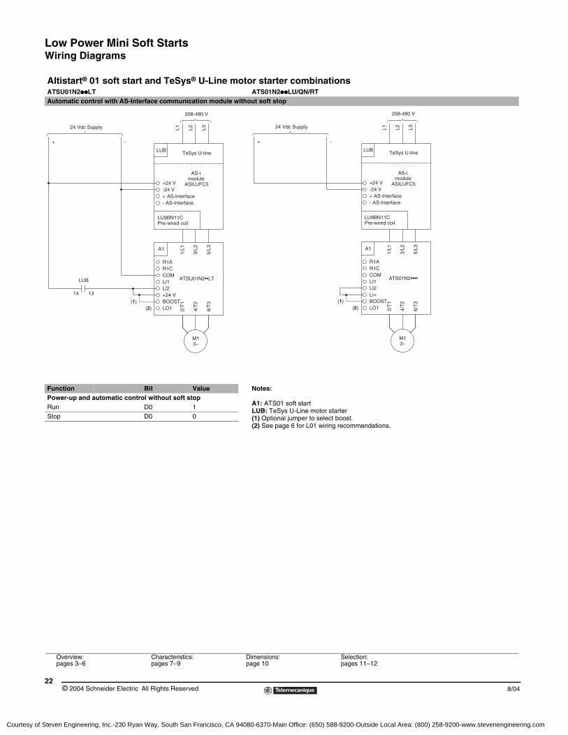
Altistart® 01 soft start and TeSys® U-Line motor starter combinationsATSU01N2ppLT ATS01N2ppLU/QN/RTAutomatic control with AS-Interface communication module without soft stop
Function Bit Value Notes:
A1: ATS01 soft startLUB: TeSys U-Line motor starter(1) Optional jumper to select boost.(2) See page 6 for L01 wiring recommendations.
Power-up and automatic control without soft stopRun D0 1Stop D0 0
Overview:pages 3–6
Characteristics:pages 7–9
Dimensions:page 10
Selection:pages 11–12
+
3~
ATSU01N2••LT
BOOST
2/T
1(1)(2) LO1
LI1
+24 VLI2
COM
A1
R1AR1C
1/L1
4/T
2
6/T
3
M1
3/L2
5/L3
module
Pre-wired coilLU9BN11C
- AS-Interface+ AS-Interface
ASILUFC5-24 V+24 V
LUB TeSys U-line
AS-i
L2L1 L3
1314
LUB
24 Vdc Supply
-
208-480 V
ATS01N2••••
3~
BOOST
2/T
1(1)(2) LO1
LI1LI2
COM
LI+
A1
R1AR1C
1/L1
6/T
3
4/T
2
M1
5/L3
3/L2
module
Pre-wired coilLU9BN11C
- AS-Interface+ AS-Interface
ASILUFC5-24 V+24 V
LUB TeSys U-line
AS-i
L2L1 L324 Vdc Supply
+ -
208-480 V
Courtesy of Steven Engineering, Inc.-230 Ryan Way, South San Francisco, CA 94080-6370-Main Office: (650) 588-9200-Outside Local Area: (800) 258-9200-www.stevenengineering.com
Low Power Mini Soft StartsWiring Diagrams
238/04 © 2004 Schneider Electric All Rights Reserved
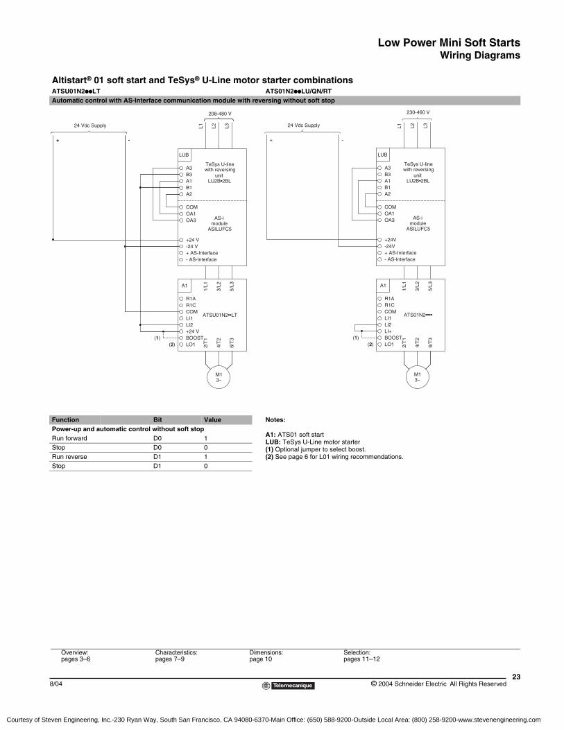
Altistart® 01 soft start and TeSys® U-Line motor starter combinationsATSU01N2ppLT ATS01N2ppLU/QN/RTAutomatic control with AS-Interface communication module with reversing without soft stop
Function Bit Value Notes:
A1: ATS01 soft startLUB: TeSys U-Line motor starter(1) Optional jumper to select boost.(2) See page 6 for L01 wiring recommendations.
Power-up and automatic control without soft stopRun forward D0 1Stop D0 0Run reverse D1 1Stop D1 0
+ AS-Interface- AS-Interface
OA3
ASILUFC5module
-24 V+24 V
A2
COMOA1
AS-i
LUB
with reversing
LU2B•2BL
TeSys U-line
A1B1
B3A3
unit
L2L1 L3
3~
ATSU01N2••LT
BOOST
2/T
1(1)(2) LO1
LI1
+24 VLI2
COM
A1
R1AR1C
1/L1
4/T
2
6/T
3
M1
3/L2
5/L3
+
24 Vdc Supply
-+ -
208-480 V
+ AS-Interface- AS-Interface
OA3
ASILUFC5module
-24V+24V
A2
COMOA1
AS-i
LUB
with reversing
LU2B•2BL
TeSys U-line
A1B1
B3A3
unit
L2L1 L3
ATS01N2••••
3~
BOOST
2/T
1(1)(2) LO1
LI1LI2
COM
LI+
A1
R1AR1C
1/L1
6/T
3
4/T
2
M1
5/L3
3/L2
24 Vdc Supply
+ -
230-460 V
Overview:pages 3–6
Characteristics:pages 7–9
Dimensions:page 10
Selection:pages 11–12
Courtesy of Steven Engineering, Inc.-230 Ryan Way, South San Francisco, CA 94080-6370-Main Office: (650) 588-9200-Outside Local Area: (800) 258-9200-www.stevenengineering.com
Low Power Mini Soft StartsWiring Diagrams
© 2004 Schneider Electric All Rights Reserved24
8/04
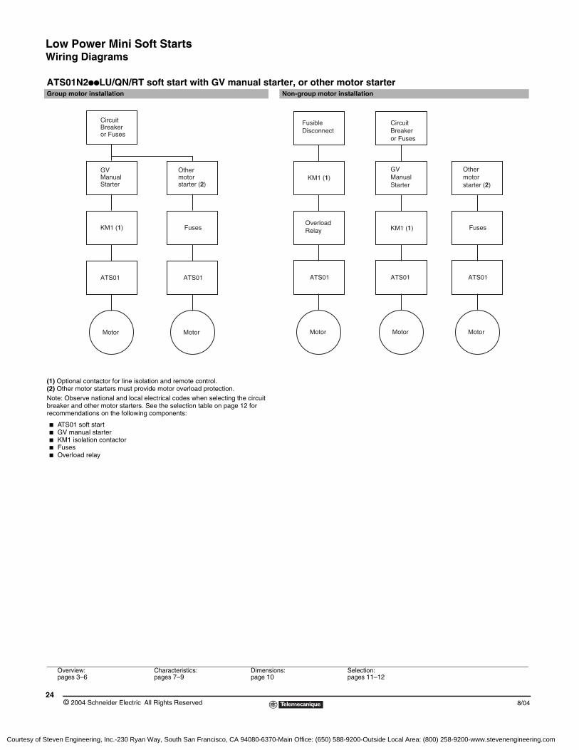
ATS01N2ppLU/QN/RT soft start with GV manual starter, or other motor starterGroup motor installation Non-group motor installation
(1) Optional contactor for line isolation and remote control.(2) Other motor starters must provide motor overload protection.Note: Observe national and local electrical codes when selecting the circuit breaker and other motor starters. See the selection table on page 12 for recommendations on the following components:
b ATS01 soft startb GV manual starterb KM1 isolation contactorb Fusesb Overload relay
CircuitBreakeror Fuses
GV ManualStarter
KM1 (1)
ATS01
Motor
Othermotorstarter (2)
Fuses
ATS01
Motor
Fusible Disconnect
GV2 or GV3
KM1 (1)
ATS01
Motor
CircuitBreakeror Fuses
KM1 (1)
ATS01
Motor
ATS01
Motor
Other motorstarter (2)
FusesOverloadRelay
GVManualStarter
Overview:pages 3–6
Characteristics:pages 7–9
Dimensions:page 10
Selection:pages 11–12
Courtesy of Steven Engineering, Inc.-230 Ryan Way, South San Francisco, CA 94080-6370-Main Office: (650) 588-9200-Outside Local Area: (800) 258-9200-www.stevenengineering.com
Low Power Mini Soft StartsWiring Diagrams
258/04 © 2004 Schneider Electric All Rights Reserved
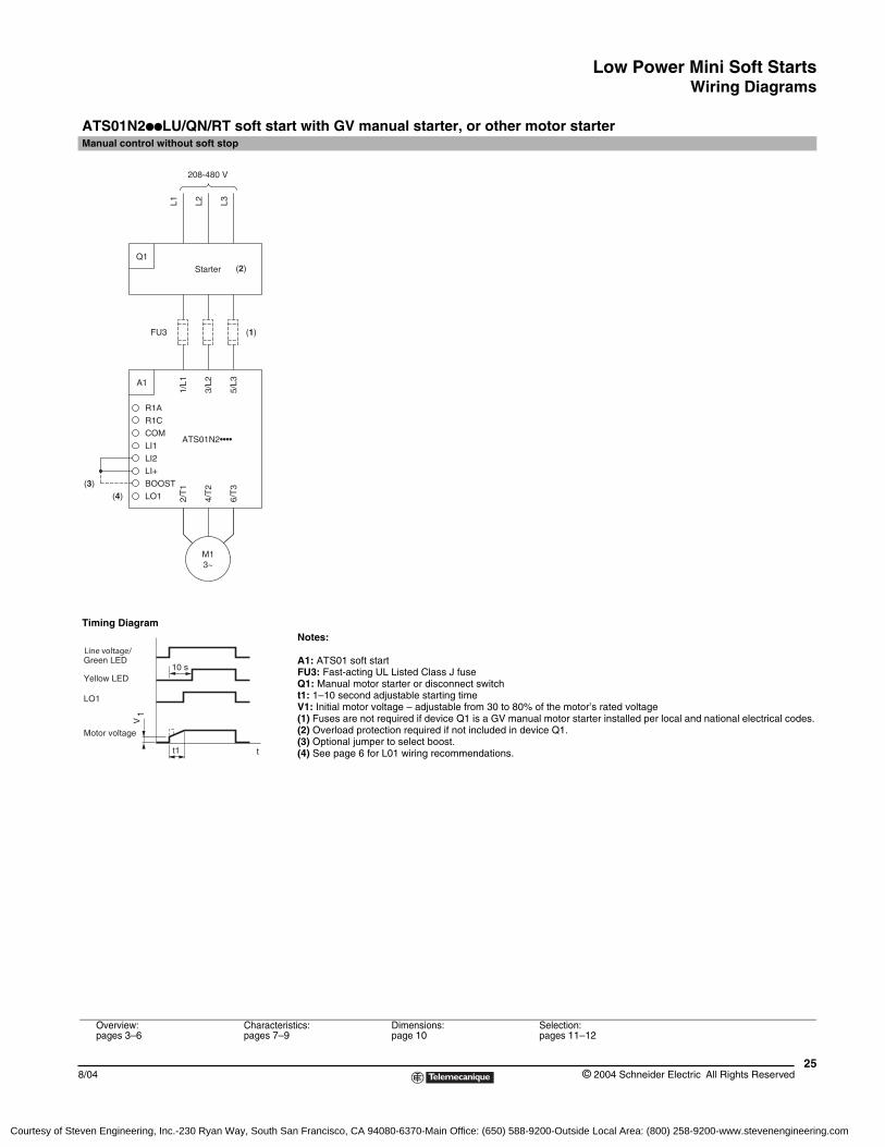
ATS01N2ppLU/QN/RT soft start with GV manual starter, or other motor starterManual control without soft stop
Timing DiagramNotes:
A1: ATS01 soft startFU3: Fast-acting UL Listed Class J fuseQ1: Manual motor starter or disconnect switcht1: 1–10 second adjustable starting timeV1: Initial motor voltage – adjustable from 30 to 80% of the motor’s rated voltage(1) Fuses are not required if device Q1 is a GV manual motor starter installed per local and national electrical codes.(2) Overload protection required if not included in device Q1.(3) Optional jumper to select boost.(4) See page 6 for L01 wiring recommendations.
FU3
3~
LI1
BOOST
(4)
(3)
LO1
LI2
LI+
M1
2/T
1
4/T
2
6/T
3
A1
COM
R1A
R1C
1/L1
5/L3
3/L2
ATS01N2••••
(1)
(2)Q1
Starter
L1208-480 V
L3L2
t1
10 s
Line voltage/Green LED
Yellow LED
Motor voltage
LO1
t
V1
Overview:pages 3–6
Characteristics:pages 7–9
Dimensions:page 10
Selection:pages 11–12
Courtesy of Steven Engineering, Inc.-230 Ryan Way, South San Francisco, CA 94080-6370-Main Office: (650) 588-9200-Outside Local Area: (800) 258-9200-www.stevenengineering.com
Low Power Mini Soft StartsWiring Diagrams
© 2004 Schneider Electric All Rights Reserved26
8/04
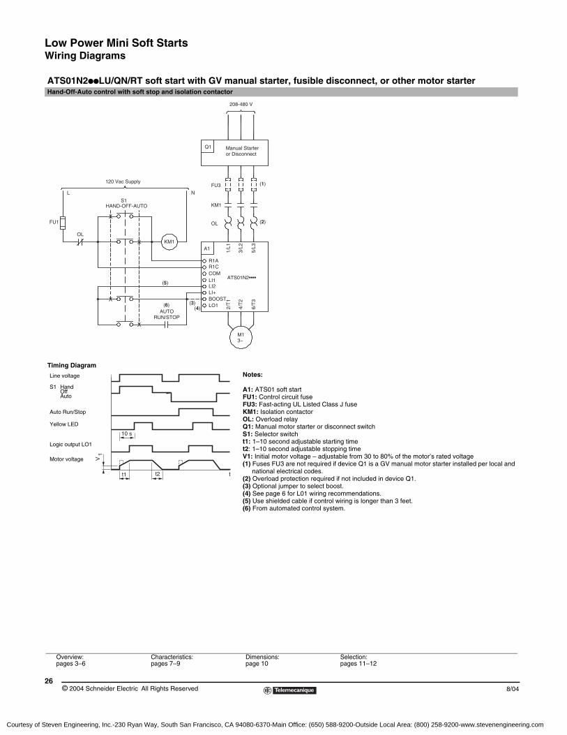
ATS01N2ppLU/QN/RT soft start with GV manual starter, fusible disconnect, or other motor starterHand-Off-Auto control with soft stop and isolation contactor
Timing DiagramNotes:
A1: ATS01 soft startFU1: Control circuit fuseFU3: Fast-acting UL Listed Class J fuseKM1: Isolation contactorOL: Overload relayQ1: Manual motor starter or disconnect switchS1: Selector switcht1: 1–10 second adjustable starting timet2: 1–10 second adjustable stopping timeV1: Initial motor voltage – adjustable from 30 to 80% of the motor’s rated voltage(1) Fuses FU3 are not required if device Q1 is a GV manual motor starter installed per local and
national electrical codes.(2) Overload protection required if not included in device Q1.(3) Optional jumper to select boost.(4) See page 6 for L01 wiring recommendations.(5) Use shielded cable if control wiring is longer than 3 feet.(6) From automated control system.
Overview:pages 3–6
Characteristics:pages 7–9
Dimensions:page 10
Selection:pages 11–12
120 Vac Supply
HAND-OFF-AUTOS1
Q1
FU1
FU3
OL
OL
KM1
KM1
A1
L N
(1)
(2)
(3)(4)
(6)
(5)
Manual Starteror Disconnect
208-480 V
1/L1
3/L2
5/L3
2/T
1
4/T
2
6/T
3R1AR1CCOMLI1
LO1
LI2LI+BOOST
M13~
AUTORUN/STOP
ATS01N2••••
tt1 t2
10 s
V1
Line voltage
Logic output LO1
Yellow LED
Motor voltage
S1 HandOffAuto
Auto Run/Stop
Courtesy of Steven Engineering, Inc.-230 Ryan Way, South San Francisco, CA 94080-6370-Main Office: (650) 588-9200-Outside Local Area: (800) 258-9200-www.stevenengineering.com
Low Power Mini Soft StartsWiring Diagrams
278/04 © 2004 Schneider Electric All Rights Reserved
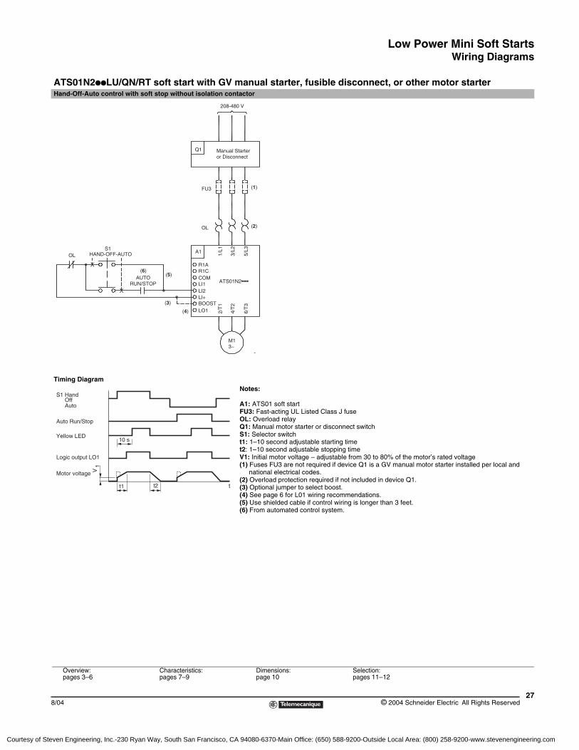
ATS01N2ppLU/QN/RT soft start with GV manual starter, fusible disconnect, or other motor starterHand-Off-Auto control with soft stop without isolation contactor
Timing DiagramNotes:
A1: ATS01 soft startFU3: Fast-acting UL Listed Class J fuseOL: Overload relayQ1: Manual motor starter or disconnect switchS1: Selector switcht1: 1–10 second adjustable starting timet2: 1–10 second adjustable stopping timeV1: Initial motor voltage – adjustable from 30 to 80% of the motor’s rated voltage(1) Fuses FU3 are not required if device Q1 is a GV manual motor starter installed per local and
national electrical codes.(2) Overload protection required if not included in device Q1.(3) Optional jumper to select boost.(4) See page 6 for L01 wiring recommendations.(5) Use shielded cable if control wiring is longer than 3 feet.(6) From automated control system.
Overview:pages 3–6
Characteristics:pages 7–9
Dimensions:page 10
Selection:pages 11–12
HAND-OFF-AUTOS1
Q1
FU3
OL
OL
A1
-
(1)
(2)
(3)
(4)
(5)(6)
Manual Starteror Disconnect
208-480 V
1/L1
3/L2
5/L3
2/T
1
4/T
2
6/T
3
R1AR1CCOMLI1
LO1
LI2LI+BOOST
M13~
AUTORUN/STOP ATS01N2••••
tt1 t2
10 s
Motor voltage
Logic output LO1
Yellow LED
Auto Run/Stop
S1 HandOffAuto
V1
Courtesy of Steven Engineering, Inc.-230 Ryan Way, South San Francisco, CA 94080-6370-Main Office: (650) 588-9200-Outside Local Area: (800) 258-9200-www.stevenengineering.com
Low Power Mini Soft StartsWiring Diagrams
© 2004 Schneider Electric All Rights Reserved28
8/04
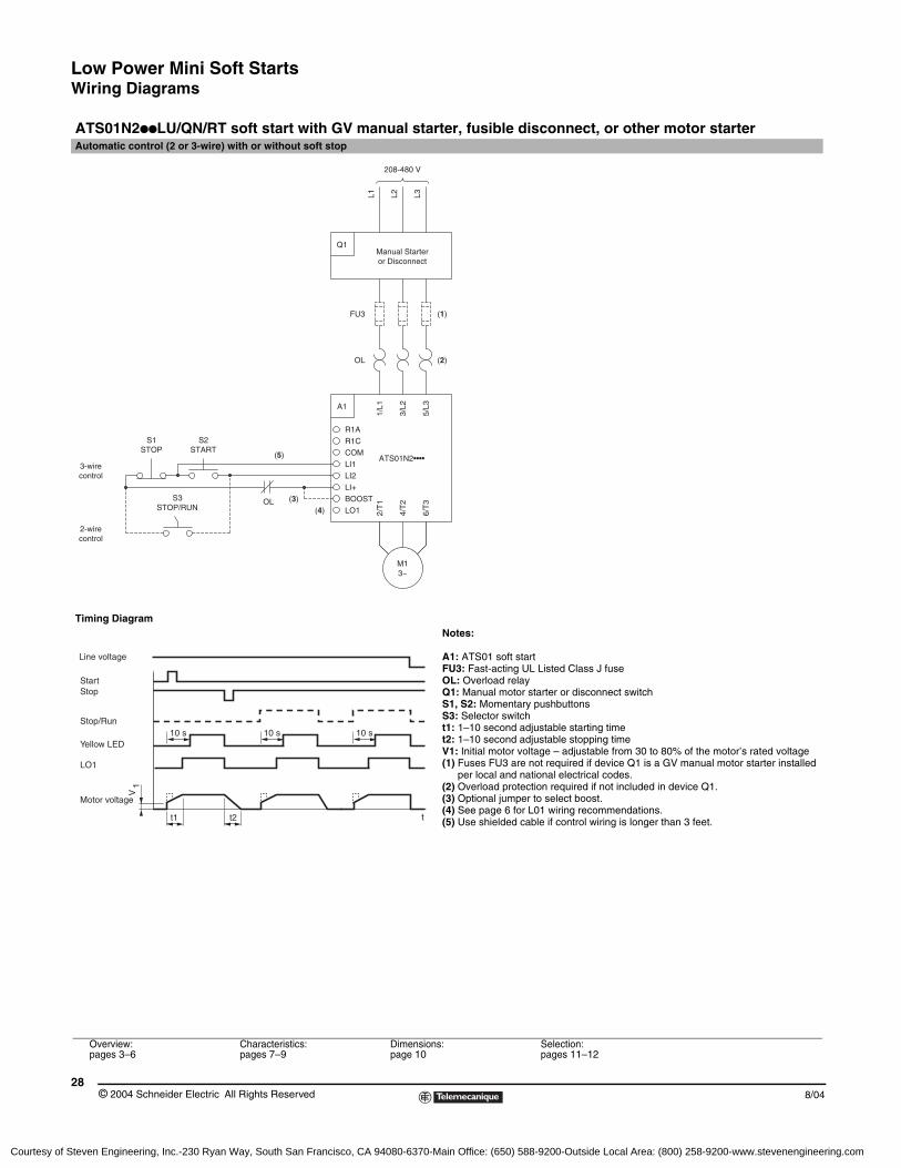
ATS01N2ppLU/QN/RT soft start with GV manual starter, fusible disconnect, or other motor starterAutomatic control (2 or 3-wire) with or without soft stop
Timing DiagramNotes:
A1: ATS01 soft startFU3: Fast-acting UL Listed Class J fuseOL: Overload relayQ1: Manual motor starter or disconnect switchS1, S2: Momentary pushbuttonsS3: Selector switcht1: 1–10 second adjustable starting timet2: 1–10 second adjustable stopping timeV1: Initial motor voltage – adjustable from 30 to 80% of the motor’s rated voltage(1) Fuses FU3 are not required if device Q1 is a GV manual motor starter installed
per local and national electrical codes.(2) Overload protection required if not included in device Q1.(3) Optional jumper to select boost.(4) See page 6 for L01 wiring recommendations.(5) Use shielded cable if control wiring is longer than 3 feet.
Overview:pages 3–6
Characteristics:pages 7–9
Dimensions:page 10
Selection:pages 11–12
3~
OL (2)
3-wire
control2-wire
control
STOP/RUNS3
S1STOP
S2START
LI1
BOOST
(4)
(3)
(5)
OL
LI2
LI+
LO1
M1
4/T
2
2/T
1
6/T
3
R1C
R1A
COM
A13/
L2
5/L3
1/L1
ATS01N2••••
Manual Starteror Disconnect
Q1
L1 L2 L3
FU3 (1)
208-480 V
t1 t2
10 s 10 s 10 s
V1
t
Yellow LED
Motor voltage
LO1
StartStop
Stop/Run
Line voltage
Courtesy of Steven Engineering, Inc.-230 Ryan Way, South San Francisco, CA 94080-6370-Main Office: (650) 588-9200-Outside Local Area: (800) 258-9200-www.stevenengineering.com
Low Power Mini Soft StartsWiring Diagrams
298/04 © 2004 Schneider Electric All Rights Reserved
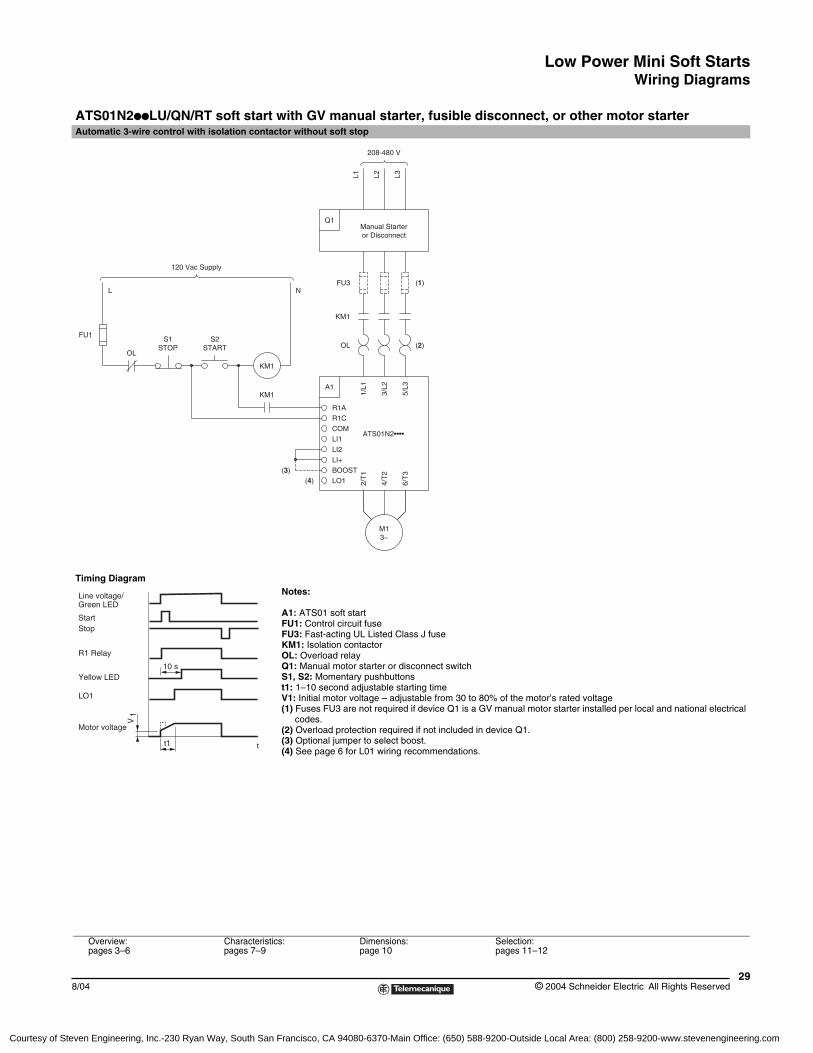
ATS01N2ppLU/QN/RT soft start with GV manual starter, fusible disconnect, or other motor starterAutomatic 3-wire control with isolation contactor without soft stop
Timing DiagramNotes:
A1: ATS01 soft startFU1: Control circuit fuseFU3: Fast-acting UL Listed Class J fuseKM1: Isolation contactorOL: Overload relayQ1: Manual motor starter or disconnect switchS1, S2: Momentary pushbuttonst1: 1–10 second adjustable starting timeV1: Initial motor voltage – adjustable from 30 to 80% of the motor’s rated voltage(1) Fuses FU3 are not required if device Q1 is a GV manual motor starter installed per local and national electrical
codes.(2) Overload protection required if not included in device Q1.(3) Optional jumper to select boost.(4) See page 6 for L01 wiring recommendations.
Overview:pages 3–6
Characteristics:pages 7–9
Dimensions:page 10
Selection:pages 11–12
KM1
BOOST
(4)
(3)
LO1
M13~
4/T
2
2/T
1
6/T
3
COM
R1C
LI+
LI2
LI1
KM1
R1A
A1
ATS01N2••••
3/L2
1/L1
5/L3
Manual Starteror Disconnect
Q1
L1 L2 L3
120 Vac Supply
STOP
FU1
OL
L
STARTS1 S2
FU3
KM1
OL
N
(2)
(1)
208-480 V
t1
10 s
V1
Line voltage/Green LED
Yellow LED
Motor voltage
LO1
StartStop
R1 Relay
t
Courtesy of Steven Engineering, Inc.-230 Ryan Way, South San Francisco, CA 94080-6370-Main Office: (650) 588-9200-Outside Local Area: (800) 258-9200-www.stevenengineering.com
Low Power Mini Soft StartsWiring Diagrams
© 2004 Schneider Electric All Rights Reserved30
8/04
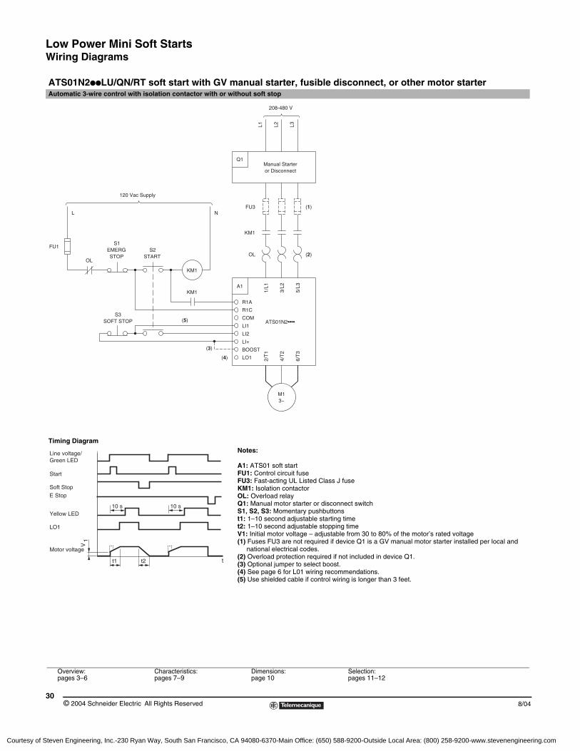
ATS01N2ppLU/QN/RT soft start with GV manual starter, fusible disconnect, or other motor starterAutomatic 3-wire control with isolation contactor with or without soft stop
Timing DiagramNotes:
A1: ATS01 soft startFU1: Control circuit fuseFU3: Fast-acting UL Listed Class J fuseKM1: Isolation contactorOL: Overload relayQ1: Manual motor starter or disconnect switchS1, S2, S3: Momentary pushbuttonst1: 1–10 second adjustable starting timet2: 1–10 second adjustable stopping timeV1: Initial motor voltage – adjustable from 30 to 80% of the motor’s rated voltage(1) Fuses FU3 are not required if device Q1 is a GV manual motor starter installed per local and
national electrical codes.(2) Overload protection required if not included in device Q1.(3) Optional jumper to select boost.(4) See page 6 for L01 wiring recommendations.(5) Use shielded cable if control wiring is longer than 3 feet.
Overview:pages 3–6
Characteristics:pages 7–9
Dimensions:page 10
Selection:pages 11–12
(1)
(2)
Manual Starteror Disconnect
Q1
L1 L2 L3
3~M1
S3SOFT STOP
OL
FU1EMERGSTOP
S1S2
START
R1C
(5)
(4)
(3)
6/T
3
4/T
2BOOST
2/T
1
LO1
ATS01N2••••LI1
LI2
LI+
COM
KM1
KM11/
L1A1
R1A5/
L3
3/L2
OL
120 Vac Supply
L NFU3
KM1
208-480 V
tt1 t2
10 s 10 s
V1
Line voltage/Green LED
Start
Soft StopE Stop
Yellow LED
Motor voltage
LO1
Courtesy of Steven Engineering, Inc.-230 Ryan Way, South San Francisco, CA 94080-6370-Main Office: (650) 588-9200-Outside Local Area: (800) 258-9200-www.stevenengineering.com
Low Power Mini Soft StartsWiring Diagrams
318/04 © 2004 Schneider Electric All Rights Reserved
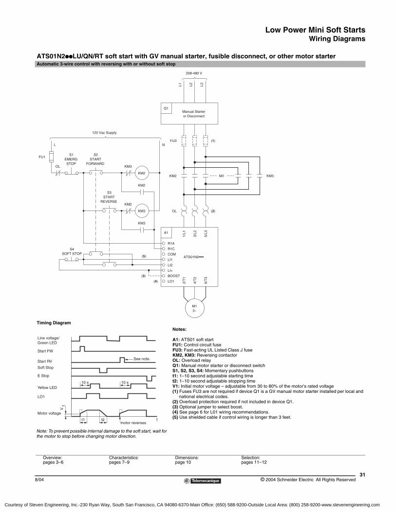
ATS01N2ppLU/QN/RT soft start with GV manual starter, fusible disconnect, or other motor starterAutomatic 3-wire control with reversing with or without soft stop
Timing DiagramNotes:
A1: ATS01 soft startFU1: Control circuit fuseFU3: Fast-acting UL Listed Class J fuseKM2, KM3: Reversing contactorOL: Overload relayQ1: Manual motor starter or disconnect switchS1, S2, S3, S4: Momentary pushbuttonst1: 1–10 second adjustable starting timet2: 1–10 second adjustable stopping timeV1: Initial motor voltage – adjustable from 30 to 80% of the motor’s rated voltage(1) Fuses FU3 are not required if device Q1 is a GV manual motor starter installed per local and
national electrical codes.(2) Overload protection required if not included in device Q1.(3) Optional jumper to select boost.(4) See page 6 for L01 wiring recommendations.(5) Use shielded cable if control wiring is longer than 3 feet.
Overview:pages 3–6
Characteristics:pages 7–9
Dimensions:page 10
Selection:pages 11–12
(2)
M13~
REVERSESTART
(5)SOFT STOP
S4
S3
(3)
(4)
LI2
BOOST
LI+
LO1 2/T
1
4/T
2
6/T
3
ATS01N2••••
R1C
R1A
COM
LI1
KM3
KM3
KM2
A1
1/L1
3/L2
5/L3
OL
Manual Starteror Disconnect
Q1
L1 L2 L3
(1)
120 Vac Supply
OL
L
FU1
STOP FORWARDEMERG
S1 S2START
KM2
KM2
KM3
N
KM2
FU3
208-480 V
M/I KM3
tt1 t2
10 s 10 s
V1
Line voltage/Green LED
Start FW
Soft Stop
E Stop
Yellow LED
Motor voltage
LO1
Start RV
motor reverses
See note.
Note: To prevent possible internal damage to the soft start, wait for the motor to stop before changing motor direction.
Courtesy of Steven Engineering, Inc.-230 Ryan Way, South San Francisco, CA 94080-6370-Main Office: (650) 588-9200-Outside Local Area: (800) 258-9200-www.stevenengineering.com
Low Power Mini Soft Starts
© 2004 Schneider Electric All Rights Reserved32
8/04
Courtesy of Steven Engineering, Inc.-230 Ryan Way, South San Francisco, CA 94080-6370-Main Office: (650) 588-9200-Outside Local Area: (800) 258-9200-www.stevenengineering.com
High Power Mini Soft StartsOverview
338/04 © 2004 Schneider Electric All Rights Reserved
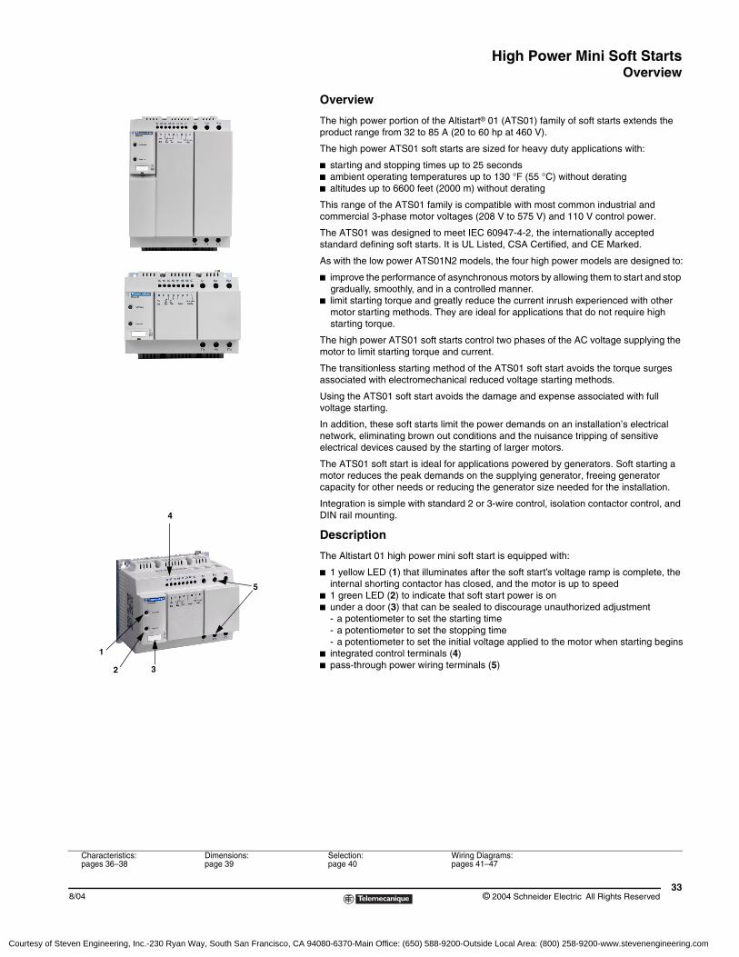
Overview
The high power portion of the Altistart® 01 (ATS01) family of soft starts extends the product range from 32 to 85 A (20 to 60 hp at 460 V).
The high power ATS01 soft starts are sized for heavy duty applications with:
b starting and stopping times up to 25 secondsb ambient operating temperatures up to 130 °F (55 °C) without deratingb altitudes up to 6600 feet (2000 m) without derating
This range of the ATS01 family is compatible with most common industrial and commercial 3-phase motor voltages (208 V to 575 V) and 110 V control power.
The ATS01 was designed to meet IEC 60947-4-2, the internationally accepted standard defining soft starts. It is UL Listed, CSA Certified, and CE Marked.
As with the low power ATS01N2 models, the four high power models are designed to:
b improve the performance of asynchronous motors by allowing them to start and stop gradually, smoothly, and in a controlled manner.
b limit starting torque and greatly reduce the current inrush experienced with other motor starting methods. They are ideal for applications that do not require high starting torque.
The high power ATS01 soft starts control two phases of the AC voltage supplying the motor to limit starting torque and current.
The transitionless starting method of the ATS01 soft start avoids the torque surges associated with electromechanical reduced voltage starting methods.
Using the ATS01 soft start avoids the damage and expense associated with full voltage starting.
In addition, these soft starts limit the power demands on an installation’s electrical network, eliminating brown out conditions and the nuisance tripping of sensitive electrical devices caused by the starting of larger motors.
The ATS01 soft start is ideal for applications powered by generators. Soft starting a motor reduces the peak demands on the supplying generator, freeing generator capacity for other needs or reducing the generator size needed for the installation.
Integration is simple with standard 2 or 3-wire control, isolation contactor control, and DIN rail mounting.
Description
The Altistart 01 high power mini soft start is equipped with:
b 1 yellow LED (1) that illuminates after the soft start’s voltage ramp is complete, the internal shorting contactor has closed, and the motor is up to speed
b 1 green LED (2) to indicate that soft start power is onb under a door (3) that can be sealed to discourage unauthorized adjustment
- a potentiometer to set the starting time - a potentiometer to set the stopping time - a potentiometer to set the initial voltage applied to the motor when starting begins
b integrated control terminals (4)b pass-through power wiring terminals (5)
1
3
5
2
4
Characteristics:pages 36–38
Dimensions:page 39
Selection:page 40
Wiring Diagrams:pages 41–47
Courtesy of Steven Engineering, Inc.-230 Ryan Way, South San Francisco, CA 94080-6370-Main Office: (650) 588-9200-Outside Local Area: (800) 258-9200-www.stevenengineering.com
High Power Mini Soft StartsFunctions
© 2004 Schneider Electric All Rights Reserved34
8/04
Altistart® 01 soft start functions
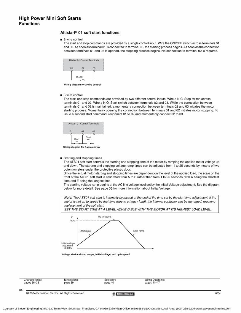
b 2-wire controlThe start and stop commands are provided by a single control input. Wire the ON/OFF switch across terminals 01 and 03. As soon as terminal 01 is connected to terminal 03, the starting process begins. As soon as the connection between terminals 01 and 03 is opened, the stopping process begins. No connection to terminal 02 is required.
b 3-wire controlThe start and stop commands are provided by two different control inputs. Wire a N.C. Stop switch across terminals 01 and 02. Wire a N.O. Start switch between terminals 02 and 03. While the connection between terminals 01 and 02 is maintained, a momentary connection between terminals 02 and 03 initiates the motor starting process. Momentarily opening the connection between terminals 01 and 02 initiates motor stopping. To issue a second start command, reconnect 01 to 02 and momentarily connect 02 to 03.
b Starting and stopping timesThe ATS01 soft start controls the starting and stopping time of the motor by ramping the applied motor voltage up and down. The starting and stopping voltage ramp times can be adjusted from 1 to 25 seconds by means of two potentiometers under the protective plastic door. Since the actual motor starting and stopping times are dependent on the level of the applied load, the scale on the front of the ATS01 soft start is calibrated from A to E rather than from 1 to 25 seconds, with A being the shortest time and E being the longest time. The starting voltage ramp begins at the AC line voltage level set by the Initial Voltage adjustment. See the diagram below for more detail. See page 35 for more information about Initial Voltage.
0201 03
Altistart 01 Control Terminals
On/Off
Wiring diagram for 2-wire control
0201 03
Altistart 01 Control Terminals
StopStart
Wiring diagram for 3-wire control
Note: The ATS01 soft start is internally bypassed at the end of the time set by the start time adjustment. If the motor is not up to speed by that time (due to a heavy load), the internal contactor can be damaged, requiring replacement of the soft start. SET THE START TIME AT A LEVEL ACHIEVABLE WITH THE MOTOR AT ITS HIGHEST LOAD LEVEL.
t
100%
Initial voltageAdjustable
30-80%
Start ramp
Up to speed
Stop ramp
V
Voltage start and stop ramps, initial voltage, and up to speed
Characteristics:pages 36–38
Dimensions:page 39
Selection:page 40
Wiring Diagrams:pages 41–47
Courtesy of Steven Engineering, Inc.-230 Ryan Way, South San Francisco, CA 94080-6370-Main Office: (650) 588-9200-Outside Local Area: (800) 258-9200-www.stevenengineering.com

High Power Mini Soft StartsFunctions
358/04 © 2004 Schneider Electric All Rights Reserved
b Initial (or starting) voltageThe initial voltage applied to the motor (the level at which the voltage ramp begins) can be adjusted by a potentiometer under the protective plastic door. The initial voltage level can be adjusted from approximately 30 to 80% of the AC line voltage. Since the resultant motor torque varies in proportion to the square of the applied voltage (see the diagram on page 6), the scale on the face of the Altistart® 01 is calibrated from A to E rather than from 30 to 80%, with A being the lowest level and E being the highest level. A lower setting will reduce motor current and torque during starting. Set this level to the minimum required that will result in motor rotation immediately after a start command.
b The Altistart 01 soft start provides a N.O. relay contact to indicate either that it has faulted or that it has stopped running the motor. The normally-open contact between terminals 04 and 05 closes upon a run command. The relay contact opens under either one of the following two conditions:
- the contact opens instantly when the soft start experiences a fault condition.- the contact opens when the motor voltage reaches zero after a stop command.
This information can be used to sequence a contactor if both line isolation and soft stop are needed in the same application.
b Motor up to speedThe ATS01 high power soft start models offer an optional snap-on contact block (N.O. and N.C. contacts) to indicate that the starting voltage ramp is complete and the motor is up to speed. To receive this optional relay contact with the ATS01 soft start, order one of part number LAD8N11 for each soft start.
b DIN rail mountingATS01 models ATS01N230LY and ATS01S44LY can be DIN rail mounted by means of an adapter kit. Order one optional DIN rail mounting kit (part number VY1H4101) for each soft start.
Characteristics:pages 36–38
Dimensions:page 39
Selection:page 40
Wiring Diagrams:pages 41–47
Courtesy of Steven Engineering, Inc.-230 Ryan Way, South San Francisco, CA 94080-6370-Main Office: (650) 588-9200-Outside Local Area: (800) 258-9200-www.stevenengineering.com
High Power Mini Soft StartsCharacteristics
© 2004 Schneider Electric All Rights Reserved36
8/04
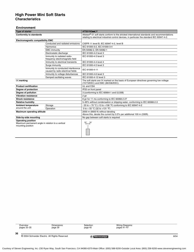
EnvironmentType of starter ATS01N2ppLYConformity to standards Altistart® 01 soft starts conform to the strictest international standards and recommendations
relating to electrical industrial control devices, in particular the standard IEC 60947-4-2.Electromagnetic compatibility EMC
CISPR 11 level B, IEC 60947-4-2, level BConducted and radiated emissionsHarmonics IEC 61000-3-2, IEC 61000-3-4EMC immunity EN 50082-2, EN 50082-1Electrostatic discharge IEC 61000-4-2 level 3Immunity to radiated radio-frequency electromagnetic field
IEC 61000-4-3 level 3
Immunity to electrical transients IEC 61000-4-4 level 4Surge immunity IEC 61000-4-5 level 3Immunity to conducted interference caused by radio-electrical fields IEC 61000-4-11
Immunity to voltage disturbances IEC 61000-4-6 level 3Damped oscillating waves IEC 61000-4-12 level 3
e marking The soft starts are e marked on the basis of European directives governing low voltage (72/73/EEC) and EMC (89/336/EEC).
Product certification UL and CSADegree of protection IP20 on front panelDegree of pollution 3 (conforming to IEC 60664-1 and UL508)Vibration resistance 2 gnShock resistance 8 gn for 11 ms conforming to IEC 60068-2-27Relative humidity 5–95% without condensation or dripping water, conforming to IEC 60068-2-3Ambient temperature around the unit
Storage - 25 to + 70 °C (-13 to +158 °F) conforming to IEC 60947-4-2Operation 0 to + 55 °C (32 to +131 °F)
Maximum operating altitude 2000 m (6600 ft) without derating Above this, derate the current by 0.5% per additional 100 m (330ft).
Side-by-side mounting No gap between soft starts is requiredOperating positionMaximum permanent angle in relation to a vertical mounting position
30˚ 30˚
Overview:pages 33–35
Dimensions:page 39
Selection:page 40
Wiring Diagrams:pages 41–47
Courtesy of Steven Engineering, Inc.-230 Ryan Way, South San Francisco, CA 94080-6370-Main Office: (650) 588-9200-Outside Local Area: (800) 258-9200-www.stevenengineering.com
High Power Mini Soft StartsCharacteristics
378/04 © 2004 Schneider Electric All Rights Reserved
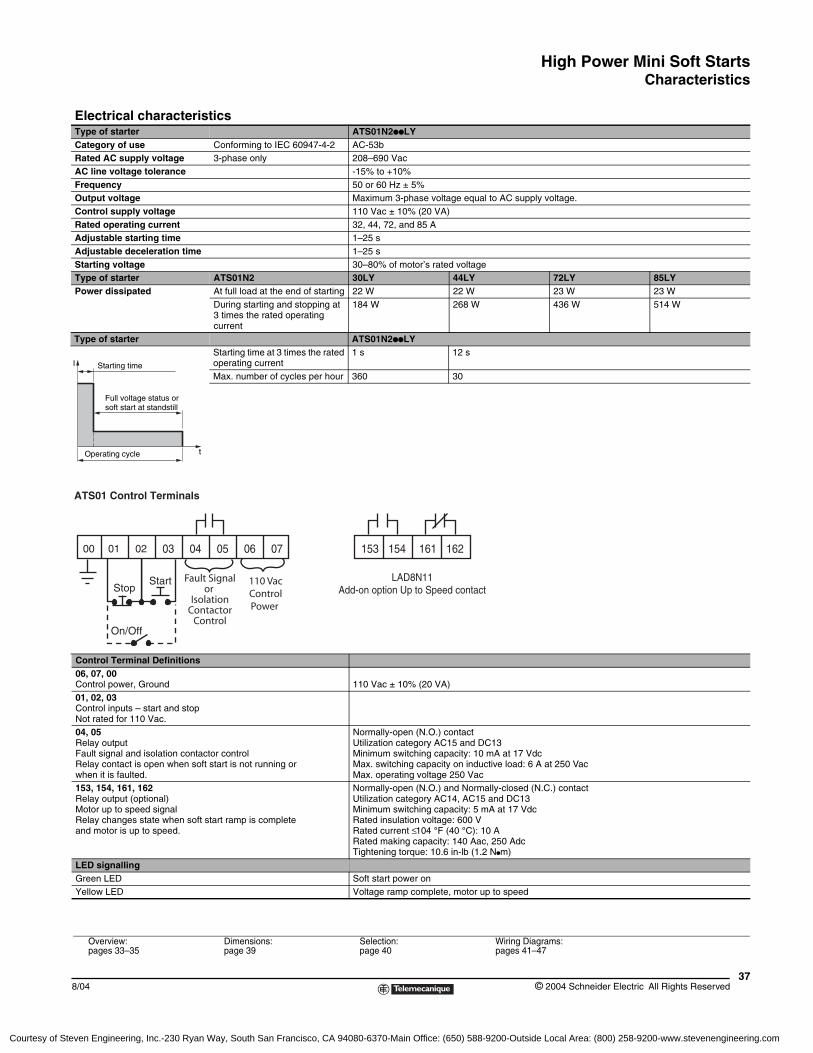
Electrical characteristicsType of starter ATS01N2ppLYCategory of use Conforming to IEC 60947-4-2 AC-53bRated AC supply voltage 3-phase only 208–690 VacAC line voltage tolerance -15% to +10%Frequency 50 or 60 Hz ± 5% Output voltage Maximum 3-phase voltage equal to AC supply voltage.Control supply voltage 110 Vac ± 10% (20 VA)Rated operating current 32, 44, 72, and 85 AAdjustable starting time 1–25 sAdjustable deceleration time 1–25 s Starting voltage 30–80% of motor’s rated voltageType of starter ATS01N2 30LY 44LY 72LY 85LYPower dissipated At full load at the end of starting 22 W 22 W 23 W 23 W
During starting and stopping at 3 times the rated operating current
184 W 268 W 436 W 514 W
Type of starter ATS01N2ppLY Starting time at 3 times the rated operating current
1 s 12 s
Max. number of cycles per hour 360 30
Control Terminal Definitions06, 07, 00Control power, Ground 110 Vac ± 10% (20 VA)01, 02, 03Control inputs – start and stopNot rated for 110 Vac.04, 05Relay outputFault signal and isolation contactor control Relay contact is open when soft start is not running or when it is faulted.
Normally-open (N.O.) contact Utilization category AC15 and DC13Minimum switching capacity: 10 mA at 17 VdcMax. switching capacity on inductive load: 6 A at 250 VacMax. operating voltage 250 Vac
153, 154, 161, 162Relay output (optional)Motor up to speed signal Relay changes state when soft start ramp is complete and motor is up to speed.
Normally-open (N.O.) and Normally-closed (N.C.) contact Utilization category AC14, AC15 and DC13Minimum switching capacity: 5 mA at 17 VdcRated insulation voltage: 600 VRated current ≤ 104 °F (40 °C): 10 ARated making capacity: 140 Aac, 250 AdcTightening torque: 10.6 in-lb (1.2 Npm)
LED signallingGreen LED Soft start power onYellow LED Voltage ramp complete, motor up to speed
Starting time
Full voltage status or soft start at standstill
Operating cycle t
I
ATS01 Control Terminals
00 01 02 03 04 05 06 07
StopStart
On/Off
153 154 161 162
Fault Signalor
IsolationContactor
Control
110 VacControlPower
LAD8N11Add-on option Up to Speed contact
Overview:pages 33–35
Dimensions:page 39
Selection:page 40
Wiring Diagrams:pages 41–47
Courtesy of Steven Engineering, Inc.-230 Ryan Way, South San Francisco, CA 94080-6370-Main Office: (650) 588-9200-Outside Local Area: (800) 258-9200-www.stevenengineering.com
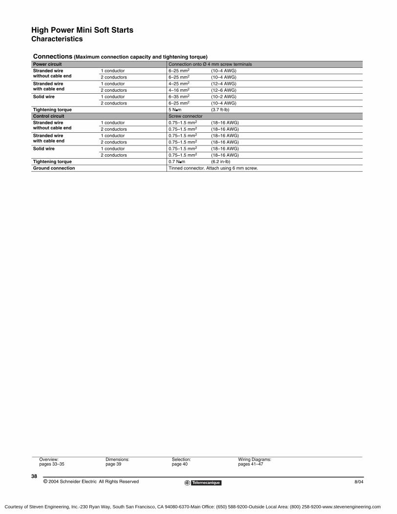
High Power Mini Soft StartsCharacteristics
© 2004 Schneider Electric All Rights Reserved38
8/04
Connections (Maximum connection capacity and tightening torque)Power circuit Connection onto Ø 4 mm screw terminalsStranded wire without cable end
1 conductor 6–25 mm2 (10–4 AWG)2 conductors 6–25 mm2 (10–4 AWG)
Stranded wire with cable end
1 conductor 4–25 mm2 (12–4 AWG)2 conductors 4–16 mm2 (12–6 AWG)
Solid wire 1 conductor 6–35 mm2 (10–2 AWG)2 conductors 6–25 mm2 (10–4 AWG)
Tightening torque 5 Npm (3.7 ft-lb)Control circuit Screw connectorStranded wire without cable end
1 conductor 0.75–1.5 mm2 (18–16 AWG)2 conductors 0.75–1.5 mm2 (18–16 AWG)
Stranded wire with cable end
1 conductor 0.75–1.5 mm2 (18–16 AWG)2 conductors 0.75–1.5 mm2 (18–16 AWG)
Solid wire 1 conductor 0.75–1.5 mm2 (18–16 AWG)2 conductors 0.75–1.5 mm2 (18–16 AWG)
Tightening torque 0.7 Npm (6.2 in-lb)Ground connection Tinned connector. Attach using 6 mm screw.
Overview:pages 33–35
Dimensions:page 39
Selection:page 40
Wiring Diagrams:pages 41–47
Courtesy of Steven Engineering, Inc.-230 Ryan Way, South San Francisco, CA 94080-6370-Main Office: (650) 588-9200-Outside Local Area: (800) 258-9200-www.stevenengineering.com
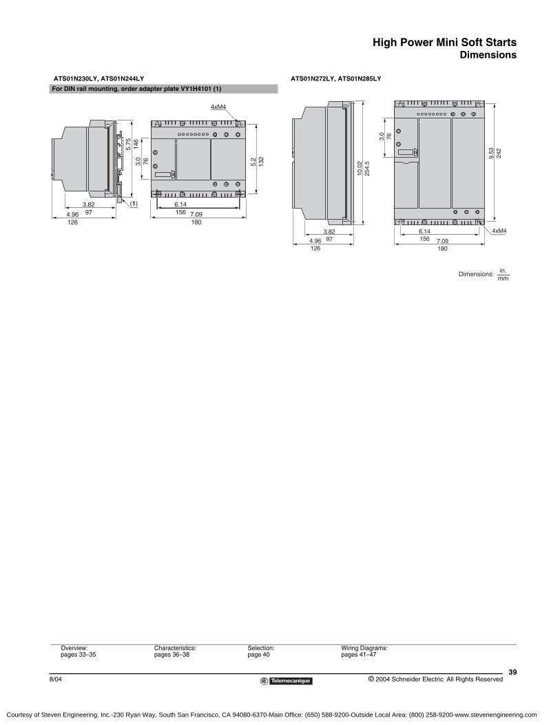
High Power Mini Soft StartsDimensions
398/04 © 2004 Schneider Electric All Rights Reserved
ATS01N230LY, ATS01N244LY ATS01N272LY, ATS01N285LY
For DIN rail mounting, order adapter plate VY1H4101 (1)
5.75
146
4.96126
3.8297
3.0
76
7.09180
5.2
132
4xM4
6.14156
(1)
10.0
225
4.5
4.96126
3.8297
3.0
76
7.09180
9.53
242
6.14156
4xM4
in.mm
Dimensions:
Overview:pages 33–35
Characteristics:pages 36–38
Selection:page 40
Wiring Diagrams:pages 41–47
Courtesy of Steven Engineering, Inc.-230 Ryan Way, South San Francisco, CA 94080-6370-Main Office: (650) 588-9200-Outside Local Area: (800) 258-9200-www.stevenengineering.com
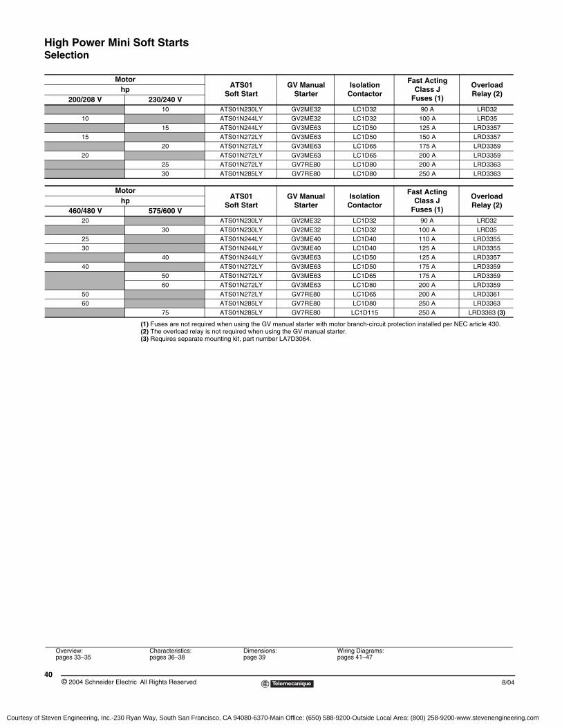
High Power Mini Soft StartsSelection
© 2004 Schneider Electric All Rights Reserved40
8/04
(1) Fuses are not required when using the GV manual starter with motor branch-circuit protection installed per NEC article 430.(2) The overload relay is not required when using the GV manual starter.(3) Requires separate mounting kit, part number LA7D3064.
MotorATS01
Soft StartGV Manual
StarterIsolation
Contactor
Fast Acting Class J
Fuses (1)
Overload Relay (2)
hp200/208 V 230/240 V
10 ATS01N230LY GV2ME32 LC1D32 90 A LRD3210 ATS01N244LY GV2ME32 LC1D32 100 A LRD35
15 ATS01N244LY GV3ME63 LC1D50 125 A LRD335715 ATS01N272LY GV3ME63 LC1D50 150 A LRD3357
20 ATS01N272LY GV3ME63 LC1D65 175 A LRD335920 ATS01N272LY GV3ME63 LC1D65 200 A LRD3359
25 ATS01N272LY GV7RE80 LC1D80 200 A LRD336330 ATS01N285LY GV7RE80 LC1D80 250 A LRD3363
MotorATS01
Soft StartGV Manual
StarterIsolation
Contactor
Fast Acting Class J
Fuses (1)
Overload Relay (2)
hp460/480 V 575/600 V
20 ATS01N230LY GV2ME32 LC1D32 90 A LRD3230 ATS01N230LY GV2ME32 LC1D32 100 A LRD35
25 ATS01N244LY GV3ME40 LC1D40 110 A LRD335530 ATS01N244LY GV3ME40 LC1D40 125 A LRD3355
40 ATS01N244LY GV3ME63 LC1D50 125 A LRD335740 ATS01N272LY GV3ME63 LC1D50 175 A LRD3359
50 ATS01N272LY GV3ME63 LC1D65 175 A LRD335960 ATS01N272LY GV3ME63 LC1D80 200 A LRD3359
50 ATS01N272LY GV7RE80 LC1D65 200 A LRD336160 ATS01N285LY GV7RE80 LC1D80 250 A LRD3363
75 ATS01N285LY GV7RE80 LC1D115 250 A LRD3363 (3)
Overview:pages 33–35
Characteristics:pages 36–38
Dimensions:page 39
Wiring Diagrams:pages 41–47
Courtesy of Steven Engineering, Inc.-230 Ryan Way, South San Francisco, CA 94080-6370-Main Office: (650) 588-9200-Outside Local Area: (800) 258-9200-www.stevenengineering.com
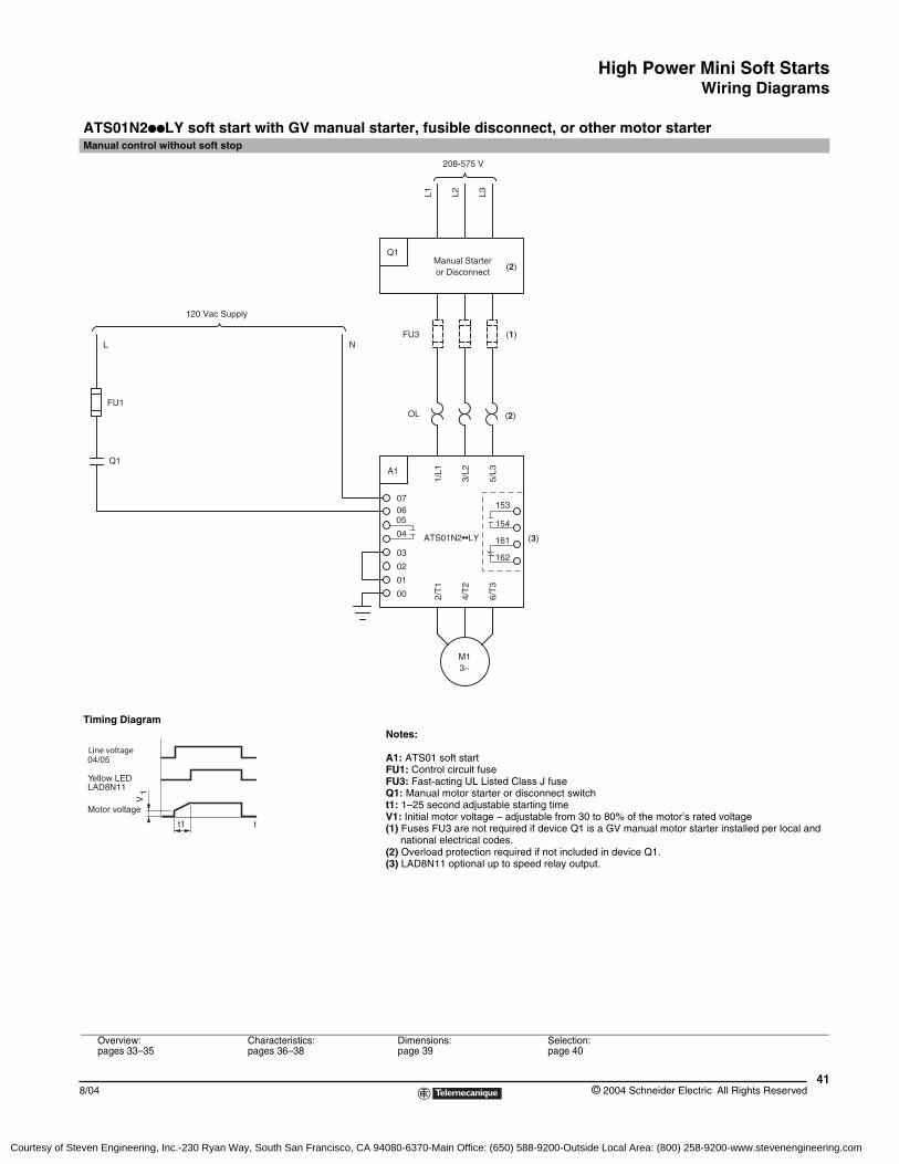
High Power Mini Soft StartsWiring Diagrams
418/04 © 2004 Schneider Electric All Rights Reserved
ATS01N2ppLY soft start with GV manual starter, fusible disconnect, or other motor starterManual control without soft stop
Timing DiagramNotes:
A1: ATS01 soft startFU1: Control circuit fuseFU3: Fast-acting UL Listed Class J fuseQ1: Manual motor starter or disconnect switcht1: 1–25 second adjustable starting timeV1: Initial motor voltage – adjustable from 30 to 80% of the motor’s rated voltage(1) Fuses FU3 are not required if device Q1 is a GV manual motor starter installed per local and
national electrical codes.(2) Overload protection required if not included in device Q1.(3) LAD8N11 optional up to speed relay output.
Overview:pages 33–35
Characteristics:pages 36–38
Dimensions:page 39
Selection:page 40
(1)
(3)
(2)Manual Starteror Disconnect
Q1
L1 L2 L3
3~M1
FU1
Q1
06
6/T
3
4/T
201
2/T
1
00
ATS01N2••LY04
03
02
05
1/L1A1
075/
L3
3/L2
120 Vac Supply
L NFU3
208-575 V
153
154
161
162
OL (2)
t1
V1
Line voltage04/05
Yellow LEDLAD8N11
Motor voltage
t
Courtesy of Steven Engineering, Inc.-230 Ryan Way, South San Francisco, CA 94080-6370-Main Office: (650) 588-9200-Outside Local Area: (800) 258-9200-www.stevenengineering.com
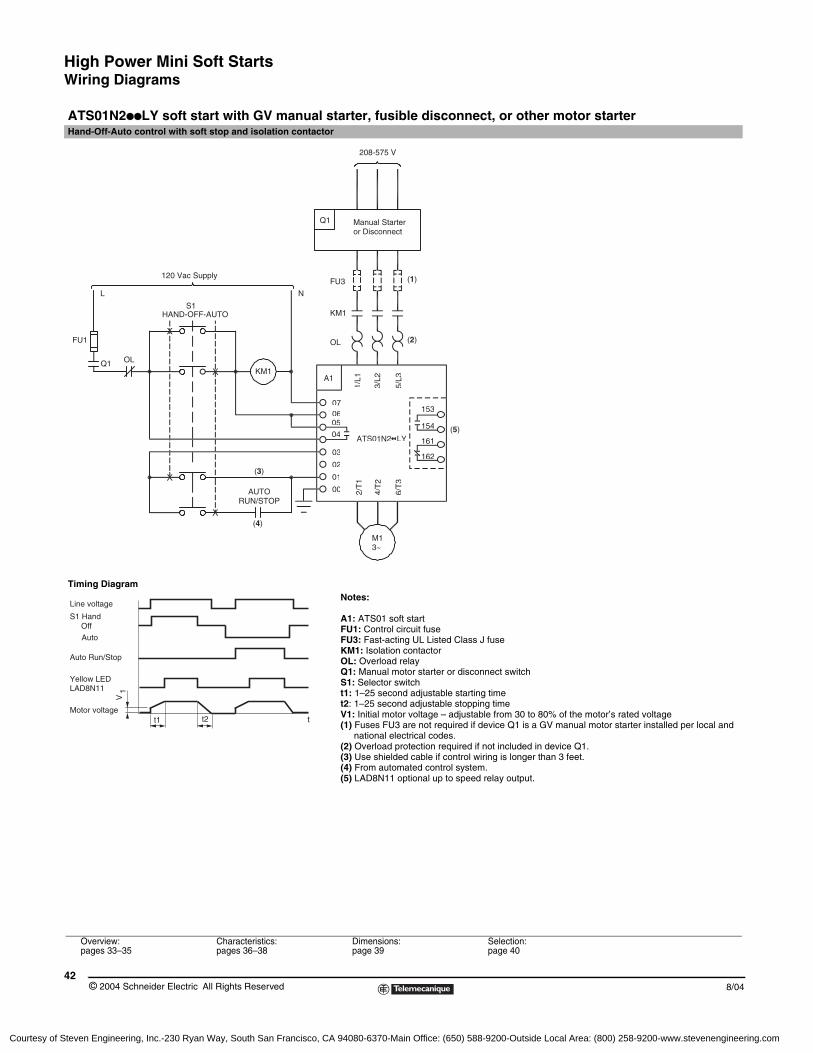
High Power Mini Soft StartsWiring Diagrams
© 2004 Schneider Electric All Rights Reserved42
8/04
ATS01N2ppLY soft start with GV manual starter, fusible disconnect, or other motor starterHand-Off-Auto control with soft stop and isolation contactor
Timing DiagramNotes:
A1: ATS01 soft startFU1: Control circuit fuseFU3: Fast-acting UL Listed Class J fuseKM1: Isolation contactorOL: Overload relayQ1: Manual motor starter or disconnect switchS1: Selector switcht1: 1–25 second adjustable starting timet2: 1–25 second adjustable stopping timeV1: Initial motor voltage – adjustable from 30 to 80% of the motor’s rated voltage(1) Fuses FU3 are not required if device Q1 is a GV manual motor starter installed per local and
national electrical codes.(2) Overload protection required if not included in device Q1.(3) Use shielded cable if control wiring is longer than 3 feet.(4) From automated control system.(5) LAD8N11 optional up to speed relay output.
Overview:pages 33–35
Characteristics:pages 36–38
Dimensions:page 39
Selection:page 40
120 Vac Supply
HAND-OFF-AUTOS1
Q1
FU1
FU3
OLQ1
OL
KM1
KM1
L N
(1)
(2)
(3)
(5)
(4)
Manual Starteror Disconnect
208-575 V
M13~
AUTORUN/STOP
06
6/T
3
4/T
201
2/T
1
00
ATS01N2••LY04
03
02
05
1/L1A1
075/
L3
3/L2
153
154
161
162
tt1 t2
V1
Line voltage
S1 HandOffAuto
Yellow LEDLAD8N11
Motor voltage
Auto Run/Stop
Courtesy of Steven Engineering, Inc.-230 Ryan Way, South San Francisco, CA 94080-6370-Main Office: (650) 588-9200-Outside Local Area: (800) 258-9200-www.stevenengineering.com
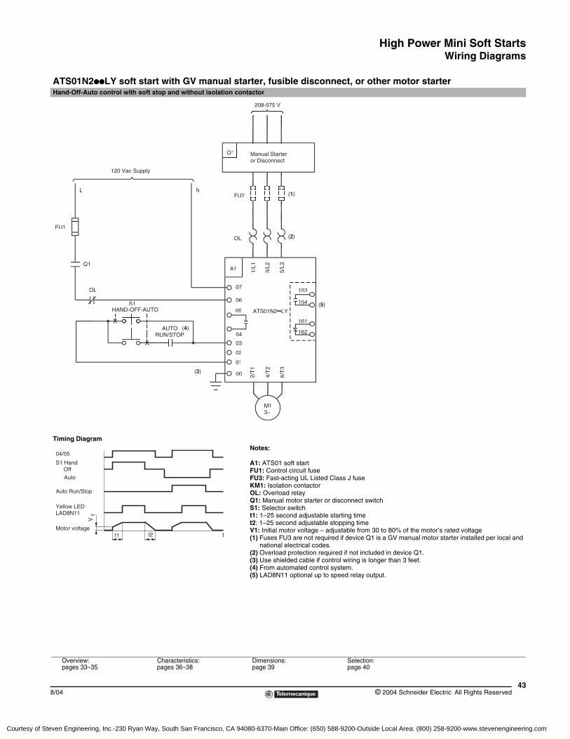
High Power Mini Soft StartsWiring Diagrams
438/04 © 2004 Schneider Electric All Rights Reserved
ATS01N2ppLY soft start with GV manual starter, fusible disconnect, or other motor starterHand-Off-Auto control with soft stop and without isolation contactor
Timing DiagramNotes:
A1: ATS01 soft startFU1: Control circuit fuseFU3: Fast-acting UL Listed Class J fuseKM1: Isolation contactorOL: Overload relayQ1: Manual motor starter or disconnect switchS1: Selector switcht1: 1–25 second adjustable starting timet2: 1–25 second adjustable stopping timeV1: Initial motor voltage – adjustable from 30 to 80% of the motor’s rated voltage(1) Fuses FU3 are not required if device Q1 is a GV manual motor starter installed per local and
national electrical codes.(2) Overload protection required if not included in device Q1.(3) Use shielded cable if control wiring is longer than 3 feet.(4) From automated control system.(5) LAD8N11 optional up to speed relay output.
Overview:pages 33–35
Characteristics:pages 36–38
Dimensions:page 39
Selection:page 40
HAND-OFF-AUTOS1
Q1
FU3
OL
OL
(1)
(2)
(3)
(4)
Manual Starteror Disconnect
208-575 V
M13~
AUTORUN/STOP
(5)06
6/T
3
4/T
2
01
2/T
1
00
ATS01N2••LY
04
03
02
05
1/L1A1
075/
L3
3/L2
153
154
161
162
FU1
Q1
120 Vac Supply
L N
tt1 t2
V1
04/05
S1 HandOffAuto
Yellow LEDLAD8N11
Motor voltage
Auto Run/Stop
Courtesy of Steven Engineering, Inc.-230 Ryan Way, South San Francisco, CA 94080-6370-Main Office: (650) 588-9200-Outside Local Area: (800) 258-9200-www.stevenengineering.com
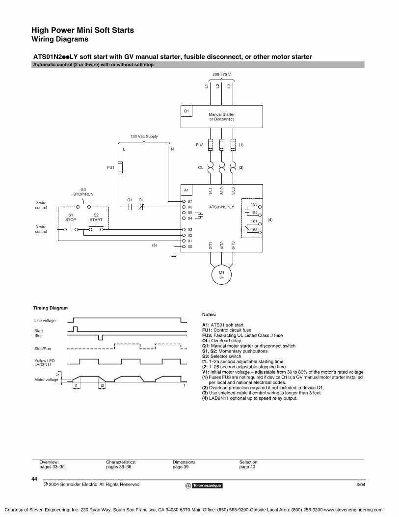
High Power Mini Soft StartsWiring Diagrams
© 2004 Schneider Electric All Rights Reserved44
8/04
ATS01N2ppLY soft start with GV manual starter, fusible disconnect, or other motor starterAutomatic control (2 or 3-wire) with or without soft stop
Timing DiagramNotes:
A1: ATS01 soft startFU1: Control circuit fuseFU3: Fast-acting UL Listed Class J fuseOL: Overload relayQ1: Manual motor starter or disconnect switchS1, S2: Momentary pushbuttonsS3: Selector switcht1: 1–25 second adjustable starting timet2: 1–25 second adjustable stopping timeV1: Initial motor voltage – adjustable from 30 to 80% of the motor’s rated voltage(1) Fuses FU3 are not required if device Q1 is a GV manual motor starter installed
per local and national electrical codes.(2) Overload protection required if not included in device Q1.(3) Use shielded cable if control wiring is longer than 3 feet.(4) LAD8N11 optional up to speed relay output.
Overview:pages 33–35
Characteristics:pages 36–38
Dimensions:page 39
Selection:page 40
S3STOP/RUN
2-wire
control
control
3-wire
S1STOP
M13~
NLFU3
ATS01N2**LY07
(3)
STARTS2
03
0100
02
4/T
2
2/T
1
04
0605
OLQ1
FU1
A1
1/L1
3/L2
OL
1626/
T3
161
154
153
(4)
5/L3
(2)
or DisconnectManual Starter
208-575 V
120 Vac Supply
Q1
L2L1
(1)
L3
t1 t2
V1
t
Yellow LEDLAD8N11
Motor voltage
StartStop
Stop/Run
Line voltage
Courtesy of Steven Engineering, Inc.-230 Ryan Way, South San Francisco, CA 94080-6370-Main Office: (650) 588-9200-Outside Local Area: (800) 258-9200-www.stevenengineering.com
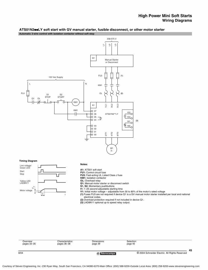
High Power Mini Soft StartsWiring Diagrams
458/04 © 2004 Schneider Electric All Rights Reserved
ATS01N2ppLY soft start with GV manual starter, fusible disconnect, or other motor starterAutomatic 3-wire control with isolation contactor without soft stop
Timing DiagramNotes:
A1: ATS01 soft startFU1: Control circuit fuseFU3: Fast-acting UL Listed Class J fuseKM1: Isolation contactorOL: Overload relayQ1: Manual motor starter or disconnect switchS1, S2: Momentary pushbuttonst1: 1–25 second adjustable starting timeV1: Initial motor voltage – adjustable from 30 to 80% of the motor’s rated voltage(1) Fuses FU3 are not required if device Q1 is a GV manual motor starter installed per local and national
electrical codes.(2) Overload protection required if not included in device Q1.(3) LAD8N11 optional up to speed relay output.
Overview:pages 33–35
Characteristics:pages 36–38
Dimensions:page 39
Selection:page 40
FU1
OLQ1
L
L2 L3L1
ATS01N2**LY
3~M1
000102
2/T
1
4/T
2
KM1
KM1
0605
03
04
07
A1
3/L2
1/L1
6/T
3154
162
161 (3)
153
5/L3
FU3
Manual Starteror Disconnect
STARTSTOPS1 S2
120 Vac Supply
OL
NKM1
Q1
(2)
(1)
208-575 V
t1
V1
Line voltage/Green LED
Yellow LEDLAD8N11
Motor voltage
StartStop
t
Courtesy of Steven Engineering, Inc.-230 Ryan Way, South San Francisco, CA 94080-6370-Main Office: (650) 588-9200-Outside Local Area: (800) 258-9200-www.stevenengineering.com
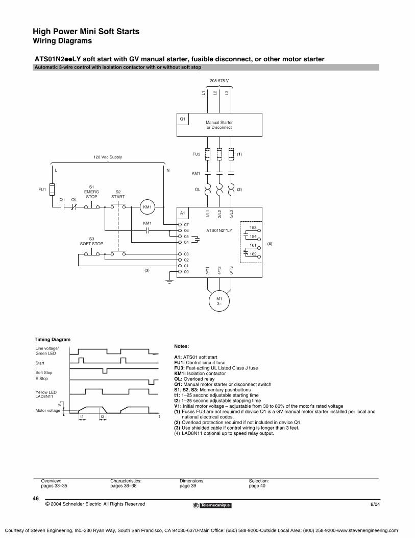
High Power Mini Soft StartsWiring Diagrams
© 2004 Schneider Electric All Rights Reserved46
8/04
ATS01N2ppLY soft start with GV manual starter, fusible disconnect, or other motor starterAutomatic 3-wire control with isolation contactor with or without soft stop
Timing DiagramNotes:
A1: ATS01 soft startFU1: Control circuit fuseFU3: Fast-acting UL Listed Class J fuseKM1: Isolation contactorOL: Overload relayQ1: Manual motor starter or disconnect switchS1, S2, S3: Momentary pushbuttonst1: 1–25 second adjustable starting timet2: 1–25 second adjustable stopping timeV1: Initial motor voltage – adjustable from 30 to 80% of the motor’s rated voltage(1) Fuses FU3 are not required if device Q1 is a GV manual motor starter installed per local and
national electrical codes.(2) Overload protection required if not included in device Q1.(3) Use shielded cable if control wiring is longer than 3 feet.(4) LAD8N11 optional up to speed relay output.
Overview:pages 33–35
Characteristics:pages 36–38
Dimensions:page 39
Selection:page 40
FU1
Q1 OL
L
04
M13~
(3)
SOFT STOP
4/T
2
2/T
1
00
0203
01
6/T
3
161
162
(4)
FU3
ATS01N2**LY
S1
KM1
KM1
S3
STARTEMERGSTOP
S2
1/L1
3/L2A1
070605
OL
120 Vac Supply
NKM1
5/L3
153
154
(2)
(1)
208-575 V
or DisconnectManual Starter
Q1
L2L1 L3
tt1 t2
V1
Line voltage/Green LED
Start
Soft StopE Stop
Yellow LEDLAD8N11
Motor voltage
Courtesy of Steven Engineering, Inc.-230 Ryan Way, South San Francisco, CA 94080-6370-Main Office: (650) 588-9200-Outside Local Area: (800) 258-9200-www.stevenengineering.com
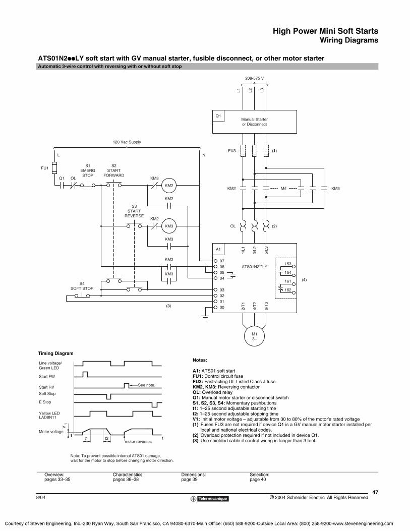
High Power Mini Soft StartsWiring Diagrams
478/04 © 2004 Schneider Electric All Rights Reserved
ATS01N2ppLY soft start with GV manual starter, fusible disconnect, or other motor starterAutomatic 3-wire control with reversing with or without soft stop
Timing DiagramNotes:
A1: ATS01 soft startFU1: Control circuit fuseFU3: Fast-acting UL Listed Class J fuseKM2, KM3: Reversing contactorOL: Overload relayQ1: Manual motor starter or disconnect switchS1, S2, S3, S4: Momentary pushbuttonst1: 1–25 second adjustable starting timet2: 1–25 second adjustable stopping timeV1: Initial motor voltage – adjustable from 30 to 80% of the motor’s rated voltage(1) Fuses FU3 are not required if device Q1 is a GV manual motor starter installed per
local and national electrical codes.(2) Overload protection required if not included in device Q1.(3) Use shielded cable if control wiring is longer than 3 feet.
Overview:pages 33–35
Characteristics:pages 36–38
Dimensions:page 39
Selection:page 40
120 Vac Supply
STARTS2
FORWARD
SOFT STOPS4
OLQ1
L
FU1EMERG
S1
STOP
S3
3~M1
ATS01N2**LY
KM2 07
(3)
KM3
0302
0001
2/T
1
4/T
2
0506
04
KM3
REVERSESTART
KM2
KM3
A13/
L2
1/L1
OL
162
6/T
3
154
153
161 (4)
5/L3
(2)
Manual Starteror Disconnect
FU3
KM3
KM2
KM2
KM2
N
Q1
(1)
KM3M/I
208-575 V
L2L1 L3
tt1 t2
V1
Line voltage/Green LED
Start FW
Soft Stop
E Stop
Yellow LEDLAD8N11
Motor voltage
Start RV
motor reverses
See note.
Note: To prevent possible internal ATS01 damage,wait for the motor to stop before changing motor direction.
Courtesy of Steven Engineering, Inc.-230 Ryan Way, South San Francisco, CA 94080-6370-Main Office: (650) 588-9200-Outside Local Area: (800) 258-9200-www.stevenengineering.com
High Power Mini Soft Starts
© 2004 Schneider Electric All Rights Reserved48
8/04
Courtesy of Steven Engineering, Inc.-230 Ryan Way, South San Francisco, CA 94080-6370-Main Office: (650) 588-9200-Outside Local Area: (800) 258-9200-www.stevenengineering.com
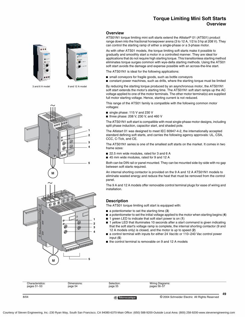
Torque Limiting Mini Soft StartsOverview
498/04 © 2004 Schneider Electric All Rights Reserved
OverviewATS01N1 torque limiting mini soft starts extend the Altistart® 01 (ATS01) product range down into the fractional horsepower arena (3 to 12 A, 1/2 to 3 hp at 208 V). They can control the starting ramp of either a single-phase or a 3-phase motor.
As with other ATS01 models, the torque limiting soft starts make it possible to gradually and smoothly start a motor in a controlled manner. They are ideal for applications that do not require high starting torque. This transitionless starting method eliminates torque surges common with wye-delta starting methods. Using the ATS01 soft start avoids the damage and expense possible with an across-the-line start.
The ATS01N1 is ideal for the following applications:
b small conveyors for fragile goods, such as bottle conveyorsb constant power machines, such as drills, where the starting torque must be limited
By reducing the starting torque produced by an asynchronous motor, the ATS01N1 soft start extends the motor’s starting time. The ATS01N1 soft start ramps up the AC voltage applied to one of the motor terminals. The other motor terminal(s) are supplied full motor starting voltage. Hence, starting current is not reduced.
This range of the ATS01 family is compatible with the following common motor voltages:
b single phase: 115 V and 230 Vb three phase: 208 V, 230 V, and 460 V
The ATS01N1 soft start is compatible with most single-phase motor designs, including split phase induction, capacitor start, and shaded pole.
The Altistart 01 was designed to meet IEC 60947-4-2, the internationally accepted standard defining soft starts, and carries the following agency approvals: UL, CSA, CCC, C-Tick, and CE.
The ATS01N1 series is one of the smallest soft starts on the market. It comes in two frame sizes:
b 22.5 mm wide modules, rated for 3 and 6 Ab 45 mm wide modules, rated for 9 and 12 A
Both can be DIN rail or panel mounted. They can be mounted side-by-side with no gap between soft starts required.
An internal shorting contactor is provided on the 9 A and 12 A ATS01N1 models to eliminate wasted energy and reduce the heat that must be removed from the control panel.
The 9 A and 12 A models offer removable control terminal plugs for ease of wiring and installation.
DescriptionThe ATS01 torque limiting soft start is equipped with:
b a potentiometer to set the starting time (3)b a potentiometer to set the initial voltage applied to the motor when starting begins (4)b 1 green LED to indicate that soft start power is on (1)b 1 yellow LED that illuminates 10 seconds after a start command is given indicating
that the soft start’s voltage ramp is complete, the internal shorting contactor (9 and 12 A models only) is closed, and the motor is up to speed (2)
b a control terminal with inputs for either 24 Vac/dc or 110–240 Vac control power input (5)
b the control terminal is removable on 9 and 12 A models
3
1
5
4
2
3 and 6 A model 9 and 12 A model
3
1
5
4
2
Characteristics:pages 51–53
Dimensions:page 54
Selection:page 55
Wiring Diagrams:pages 56–57
Courtesy of Steven Engineering, Inc.-230 Ryan Way, South San Francisco, CA 94080-6370-Main Office: (650) 588-9200-Outside Local Area: (800) 258-9200-www.stevenengineering.com
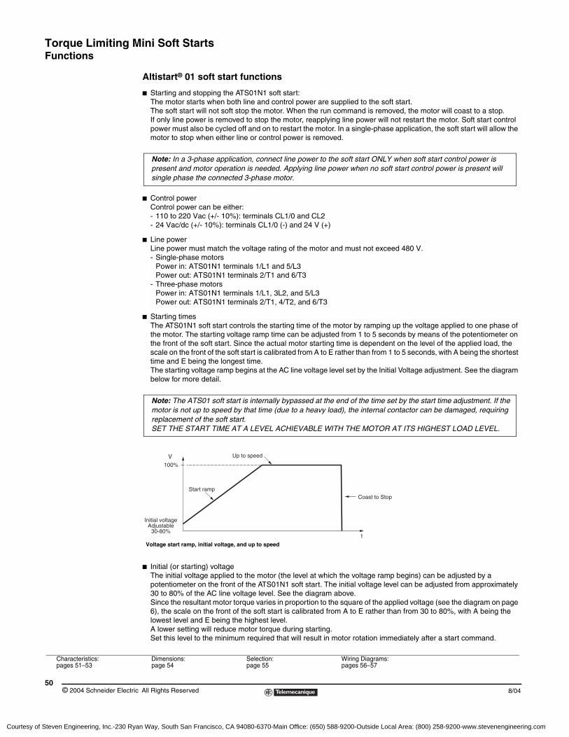
Torque Limiting Mini Soft StartsFunctions
© 2004 Schneider Electric All Rights Reserved50
8/04
Altistart® 01 soft start functions
b Starting and stopping the ATS01N1 soft start:The motor starts when both line and control power are supplied to the soft start. The soft start will not soft stop the motor. When the run command is removed, the motor will coast to a stop. If only line power is removed to stop the motor, reapplying line power will not restart the motor. Soft start control power must also be cycled off and on to restart the motor. In a single-phase application, the soft start will allow the motor to stop when either line or control power is removed.
b Control powerControl power can be either:- 110 to 220 Vac (+/- 10%): terminals CL1/0 and CL2- 24 Vac/dc (+/- 10%): terminals CL1/0 (-) and 24 V (+)
b Line powerLine power must match the voltage rating of the motor and must not exceed 480 V.- Single-phase motors
Power in: ATS01N1 terminals 1/L1 and 5/L3Power out: ATS01N1 terminals 2/T1 and 6/T3
- Three-phase motorsPower in: ATS01N1 terminals 1/L1, 3L2, and 5/L3Power out: ATS01N1 terminals 2/T1, 4/T2, and 6/T3
b Starting timesThe ATS01N1 soft start controls the starting time of the motor by ramping up the voltage applied to one phase of the motor. The starting voltage ramp time can be adjusted from 1 to 5 seconds by means of the potentiometer on the front of the soft start. Since the actual motor starting time is dependent on the level of the applied load, the scale on the front of the soft start is calibrated from A to E rather than from 1 to 5 seconds, with A being the shortest time and E being the longest time. The starting voltage ramp begins at the AC line voltage level set by the Initial Voltage adjustment. See the diagram below for more detail.
b Initial (or starting) voltageThe initial voltage applied to the motor (the level at which the voltage ramp begins) can be adjusted by a potentiometer on the front of the ATS01N1 soft start. The initial voltage level can be adjusted from approximately 30 to 80% of the AC line voltage level. See the diagram above.Since the resultant motor torque varies in proportion to the square of the applied voltage (see the diagram on page 6), the scale on the front of the soft start is calibrated from A to E rather than from 30 to 80%, with A being the lowest level and E being the highest level. A lower setting will reduce motor torque during starting.Set this level to the minimum required that will result in motor rotation immediately after a start command.
Characteristics:pages 51–53
Dimensions:page 54
Selection:page 55
Wiring Diagrams:pages 56–57
Note: In a 3-phase application, connect line power to the soft start ONLY when soft start control power is present and motor operation is needed. Applying line power when no soft start control power is present will single phase the connected 3-phase motor.
Note: The ATS01 soft start is internally bypassed at the end of the time set by the start time adjustment. If the motor is not up to speed by that time (due to a heavy load), the internal contactor can be damaged, requiring replacement of the soft start. SET THE START TIME AT A LEVEL ACHIEVABLE WITH THE MOTOR AT ITS HIGHEST LOAD LEVEL.
t
100%
Initial voltageAdjustable
30-80%
Start ramp
Up to speed
Coast to Stop
V
Voltage start ramp, initial voltage, and up to speed
Courtesy of Steven Engineering, Inc.-230 Ryan Way, South San Francisco, CA 94080-6370-Main Office: (650) 588-9200-Outside Local Area: (800) 258-9200-www.stevenengineering.com
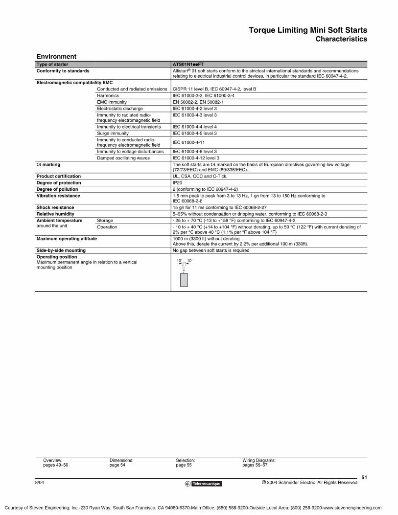
Torque Limiting Mini Soft StartsCharacteristics
518/04 © 2004 Schneider Electric All Rights Reserved
EnvironmentType of starter ATS01N1ppFTConformity to standards Altistart® 01 soft starts conform to the strictest international standards and recommendations
relating to electrical industrial control devices, in particular the standard IEC 60947-4-2.Electromagnetic compatibility EMC
CISPR 11 level B, IEC 60947-4-2, level BConducted and radiated emissionsHarmonics IEC 61000-3-2, IEC 61000-3-4EMC immunity EN 50082-2, EN 50082-1Electrostatic discharge IEC 61000-4-2 level 3Immunity to radiated radio-frequency electromagnetic field
IEC 61000-4-3 level 3
Immunity to electrical transients IEC 61000-4-4 level 4Surge immunity IEC 61000-4-5 level 3Immunity to conducted radio-frequency electromagnetic field IEC 61000-4-11
Immunity to voltage disturbances IEC 61000-4-6 level 3Damped oscillating waves IEC 61000-4-12 level 3
e marking The soft starts are e marked on the basis of European directives governing low voltage (72/73/EEC) and EMC (89/336/EEC).
Product certification UL, CSA, CCC and C-Tick.Degree of protection IP20 Degree of pollution 2 (conforming to IEC 60947-4-2)Vibration resistance 1.5 mm peak to peak from 3 to 13 Hz, 1 gn from 13 to 150 Hz conforming to
IEC 60068-2-6Shock resistance 15 gn for 11 ms conforming to IEC 60068-2-27Relative humidity 5–95% without condensation or dripping water, conforming to IEC 60068-2-3Ambient temperature around the unit
Storage - 25 to + 70 °C (-13 to +158 °F) conforming to IEC 60947-4-2Operation - 10 to + 40 °C (+14 to +104 °F) without derating, up to 50 °C (122 °F) with current derating of
2% per °C above 40 °C (1.1% per °F above 104 °F)Maximum operating altitude 1000 m (3300 ft) without derating
Above this, derate the current by 2.2% per additional 100 m (330ft).Side-by-side mounting No gap between soft starts is requiredOperating positionMaximum permanent angle in relation to a vertical mounting position
10˚ 10˚
Overview:pages 49–50
Dimensions:page 54
Selection:page 55
Wiring Diagrams:pages 56–57
Courtesy of Steven Engineering, Inc.-230 Ryan Way, South San Francisco, CA 94080-6370-Main Office: (650) 588-9200-Outside Local Area: (800) 258-9200-www.stevenengineering.com
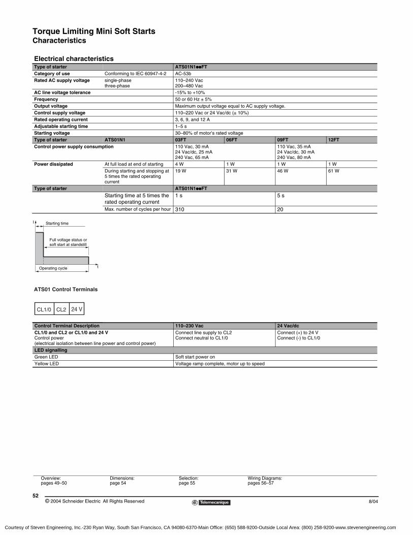
Torque Limiting Mini Soft StartsCharacteristics
© 2004 Schneider Electric All Rights Reserved52
8/04
Electrical characteristicsType of starter ATS01N1ppFTCategory of use Conforming to IEC 60947-4-2 AC-53bRated AC supply voltage single-phase
three-phase110–240 Vac200–480 Vac
AC line voltage tolerance -15% to +10%Frequency 50 or 60 Hz ± 5% Output voltage Maximum output voltage equal to AC supply voltage.Control supply voltage 110–220 Vac or 24 Vac/dc (± 10%)Rated operating current 3, 6, 9, and 12 AAdjustable starting time 1–5 sStarting voltage 30–80% of motor’s rated voltageType of starter ATS01N1 03FT 06FT 09FT 12FTControl power supply consumption 110 Vac, 30 mA
24 Vac/dc, 25 mA 240 Vac, 65 mA
110 Vac, 35 mA 24 Vac/dc, 30 mA 240 Vac, 80 mA
Power dissipated At full load at end of starting 4 W 1 W 1 W 1 WDuring starting and stopping at 5 times the rated operating current
19 W 31 W 46 W 61 W
Type of starter ATS01N1ppFT
Starting time at 5 times the rated operating current
1 s 5 s
Max. number of cycles per hour 310 20
Control Terminal Description 110–230 Vac 24 Vac/dcCL1/0 and CL2 or CL1/0 and 24 VControl power(electrical isolation between line power and control power)
Connect line supply to CL2 Connect neutral to CL1/0
Connect (+) to 24 VConnect (-) to CL1/0
LED signallingGreen LED Soft start power onYellow LED Voltage ramp complete, motor up to speed
Starting time
Full voltage status or soft start at standstill
Operating cycle t
I
ATS01 Control Terminals
CL1/0 CL2 24 V
Overview:pages 49–50
Dimensions:page 54
Selection:page 55
Wiring Diagrams:pages 56–57
Courtesy of Steven Engineering, Inc.-230 Ryan Way, South San Francisco, CA 94080-6370-Main Office: (650) 588-9200-Outside Local Area: (800) 258-9200-www.stevenengineering.com
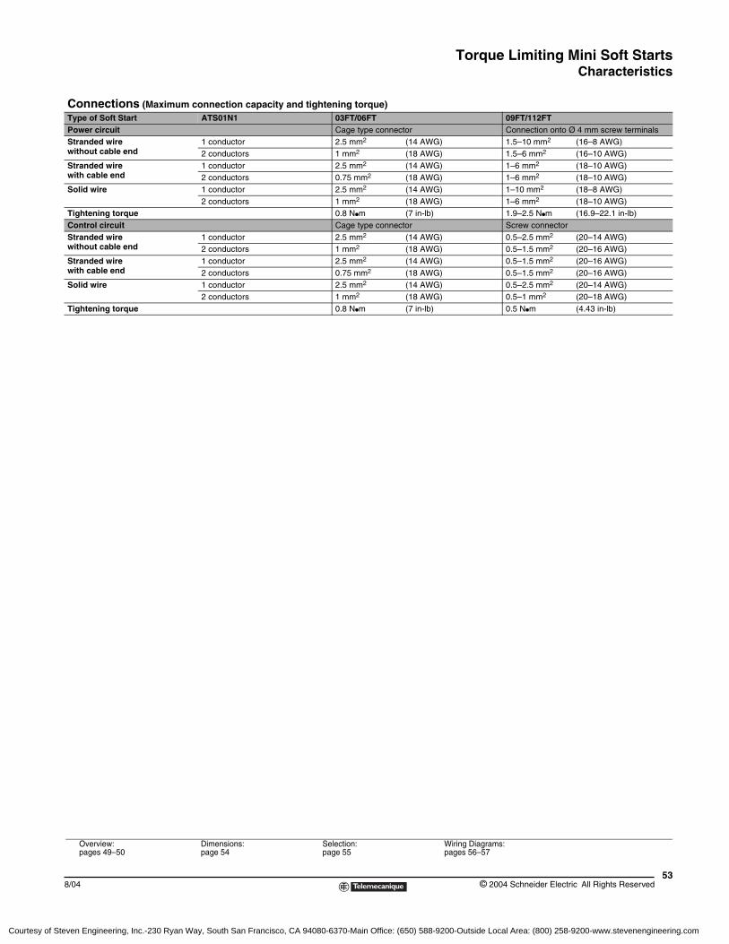
Torque Limiting Mini Soft StartsCharacteristics
538/04 © 2004 Schneider Electric All Rights Reserved
Connections (Maximum connection capacity and tightening torque)Type of Soft Start ATS01N1 03FT/06FT 09FT/112FTPower circuit Cage type connector Connection onto Ø 4 mm screw terminalsStranded wire without cable end
1 conductor 2.5 mm2 (14 AWG) 1.5–10 mm2 (16–8 AWG)2 conductors 1 mm2 (18 AWG) 1.5–6 mm2 (16–10 AWG)
Stranded wire with cable end
1 conductor 2.5 mm2 (14 AWG) 1–6 mm2 (18–10 AWG)2 conductors 0.75 mm2 (18 AWG) 1–6 mm2 (18–10 AWG)
Solid wire 1 conductor 2.5 mm2 (14 AWG) 1–10 mm2 (18–8 AWG)2 conductors 1 mm2 (18 AWG) 1–6 mm2 (18–10 AWG)
Tightening torque 0.8 Npm (7 in-lb) 1.9–2.5 Npm (16.9–22.1 in-lb)Control circuit Cage type connector Screw connectorStranded wire without cable end
1 conductor 2.5 mm2 (14 AWG) 0.5–2.5 mm2 (20–14 AWG)2 conductors 1 mm2 (18 AWG) 0.5–1.5 mm2 (20–16 AWG)
Stranded wire with cable end
1 conductor 2.5 mm2 (14 AWG) 0.5–1.5 mm2 (20–16 AWG)2 conductors 0.75 mm2 (18 AWG) 0.5–1.5 mm2 (20–16 AWG)
Solid wire 1 conductor 2.5 mm2 (14 AWG) 0.5–2.5 mm2 (20–14 AWG)2 conductors 1 mm2 (18 AWG) 0.5–1 mm2 (20–18 AWG)
Tightening torque 0.8 Npm (7 in-lb) 0.5 Npm (4.43 in-lb)
Overview:pages 49–50
Dimensions:page 54
Selection:page 55
Wiring Diagrams:pages 56–57
Courtesy of Steven Engineering, Inc.-230 Ryan Way, South San Francisco, CA 94080-6370-Main Office: (650) 588-9200-Outside Local Area: (800) 258-9200-www.stevenengineering.com
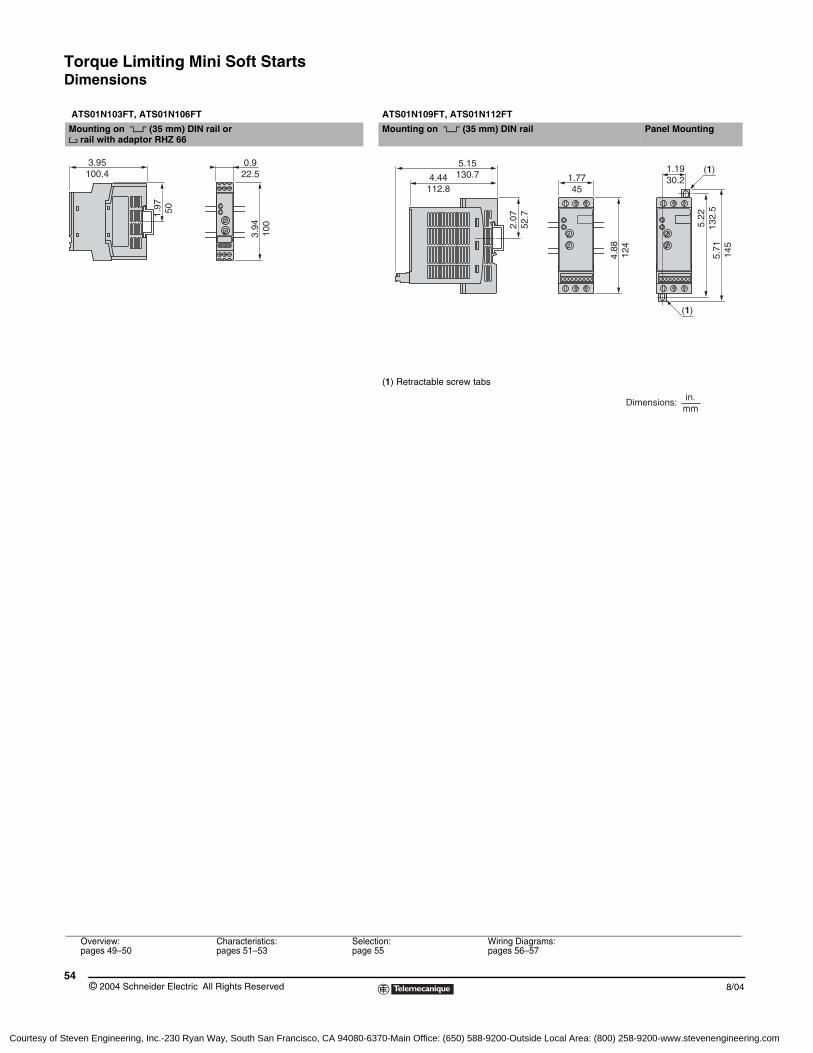
Torque Limiting Mini Soft StartsDimensions
© 2004 Schneider Electric All Rights Reserved54
8/04
ATS01N103FT, ATS01N106FT ATS01N109FT, ATS01N112FT
Mounting on 5 (35 mm) DIN rail or 4 rail with adaptor RHZ 66
Mounting on 5 (35 mm) DIN rail Panel Mounting
(1) Retractable screw tabs
3.95100.4
0.922.5
1.97 50
3.94
100
1.7745
2.07
52.7
4.88
124
5.22
132.
55.
7114
5
4.44112.8
5.15130.7
1.1930.2
(1)
(1)
in.mm
Dimensions:
Overview:pages 49–50
Characteristics:pages 51–53
Selection:page 55
Wiring Diagrams:pages 56–57
Courtesy of Steven Engineering, Inc.-230 Ryan Way, South San Francisco, CA 94080-6370-Main Office: (650) 588-9200-Outside Local Area: (800) 258-9200-www.stevenengineering.com
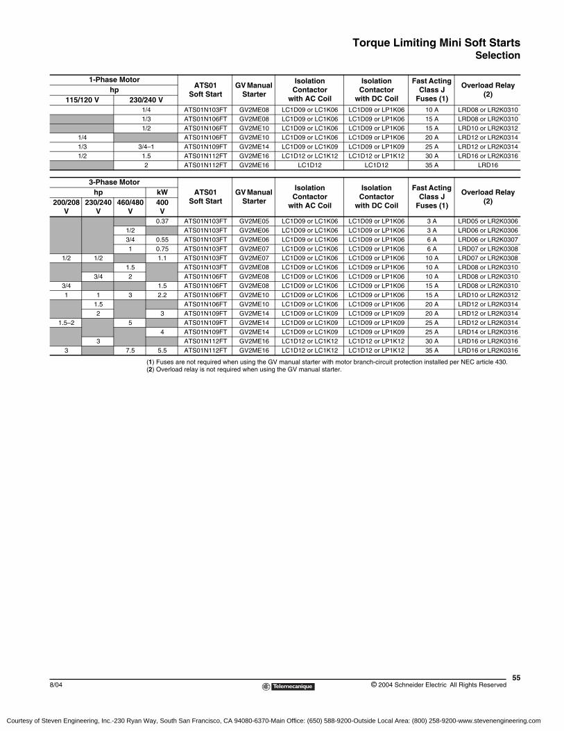
Torque Limiting Mini Soft StartsSelection
558/04 © 2004 Schneider Electric All Rights Reserved
(1) Fuses are not required when using the GV manual starter with motor branch-circuit protection installed per NEC article 430.(2) Overload relay is not required when using the GV manual starter.
1-Phase MotorATS01
Soft StartGV Manual
Starter
Isolation Contactor
with AC Coil
Isolation Contactor
with DC Coil
Fast Acting Class J
Fuses (1)
Overload Relay (2)
hp115/120 V 230/240 V
1/4 ATS01N103FT GV2ME08 LC1D09 or LC1K06 LC1D09 or LP1K06 10 A LRD08 or LR2K03101/3 ATS01N106FT GV2ME08 LC1D09 or LC1K06 LC1D09 or LP1K06 15 A LRD08 or LR2K03101/2 ATS01N106FT GV2ME10 LC1D09 or LC1K06 LC1D09 or LP1K06 15 A LRD10 or LR2K0312
1/4 ATS01N106FT GV2ME10 LC1D09 or LC1K06 LC1D09 or LP1K06 20 A LRD12 or LR2K03141/3 3/4–1 ATS01N109FT GV2ME14 LC1D09 or LC1K09 LC1D09 or LP1K09 25 A LRD12 or LR2K03141/2 1.5 ATS01N112FT GV2ME16 LC1D12 or LC1K12 LC1D12 or LP1K12 30 A LRD16 or LR2K0316
2 ATS01N112FT GV2ME16 LC1D12 LC1D12 35 A LRD16
3-Phase MotorATS01
Soft StartGV Manual
Starter
Isolation Contactor
with AC Coil
Isolation Contactor
with DC Coil
Fast Acting Class J
Fuses (1)
Overload Relay (2)
hp kW200/208
V230/240
V460/480
V400V
0.37 ATS01N103FT GV2ME05 LC1D09 or LC1K06 LC1D09 or LP1K06 3 A LRD05 or LR2K03061/2 ATS01N103FT GV2ME06 LC1D09 or LC1K06 LC1D09 or LP1K06 3 A LRD06 or LR2K03063/4 0.55 ATS01N103FT GV2ME06 LC1D09 or LC1K06 LC1D09 or LP1K06 6 A LRD06 or LR2K03071 0.75 ATS01N103FT GV2ME07 LC1D09 or LC1K06 LC1D09 or LP1K06 6 A LRD07 or LR2K0308
1/2 1/2 1.1 ATS01N103FT GV2ME07 LC1D09 or LC1K06 LC1D09 or LP1K06 10 A LRD07 or LR2K03081.5 ATS01N103FT GV2ME08 LC1D09 or LC1K06 LC1D09 or LP1K06 10 A LRD08 or LR2K0310
3/4 2 ATS01N106FT GV2ME08 LC1D09 or LC1K06 LC1D09 or LP1K06 10 A LRD08 or LR2K03103/4 1.5 ATS01N106FT GV2ME08 LC1D09 or LC1K06 LC1D09 or LP1K06 15 A LRD08 or LR2K03101 1 3 2.2 ATS01N106FT GV2ME10 LC1D09 or LC1K06 LC1D09 or LP1K06 15 A LRD10 or LR2K0312
1.5 ATS01N106FT GV2ME10 LC1D09 or LC1K06 LC1D09 or LP1K06 20 A LRD12 or LR2K03142 3 ATS01N109FT GV2ME14 LC1D09 or LC1K09 LC1D09 or LP1K09 20 A LRD12 or LR2K0314
1.5–2 5 ATS01N109FT GV2ME14 LC1D09 or LC1K09 LC1D09 or LP1K09 25 A LRD12 or LR2K03144 ATS01N109FT GV2ME14 LC1D09 or LC1K09 LC1D09 or LP1K09 25 A LRD14 or LR2K0316
3 ATS01N112FT GV2ME16 LC1D12 or LC1K12 LC1D12 or LP1K12 30 A LRD16 or LR2K03163 7.5 5.5 ATS01N112FT GV2ME16 LC1D12 or LC1K12 LC1D12 or LP1K12 35 A LRD16 or LR2K0316
Courtesy of Steven Engineering, Inc.-230 Ryan Way, South San Francisco, CA 94080-6370-Main Office: (650) 588-9200-Outside Local Area: (800) 258-9200-www.stevenengineering.com
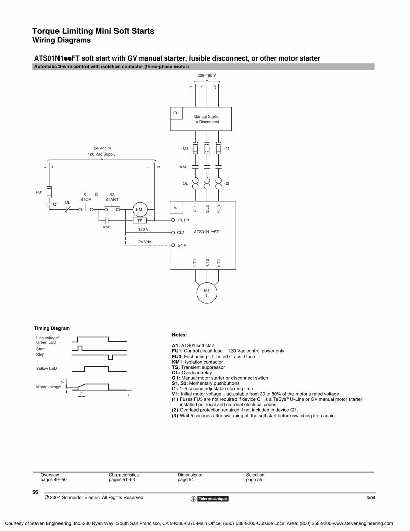
Torque Limiting Mini Soft StartsWiring Diagrams
© 2004 Schneider Electric All Rights Reserved56
8/04
ATS01N1ppFT soft start with GV manual starter, fusible disconnect, or other motor starterAutomatic 3-wire control with isolation contactor (three-phase motor)
Timing DiagramNotes:
A1: ATS01 soft startFU1: Control circuit fuse – 120 Vac control power onlyFU3: Fast-acting UL Listed Class J fuseKM1: Isolation contactorTS: Transient suppressor OL: Overload relayQ1: Manual motor starter or disconnect switchS1, S2: Momentary pushbuttonst1: 1–5 second adjustable starting timeV1: Initial motor voltage – adjustable from 30 to 80% of the motor’s rated voltage(1) Fuses FU3 are not required if device Q1 is a TeSys® U-Line or GV manual motor starter
installed per local and national electrical codes.(2) Overload protection required if not included in device Q1.(3) Wait 5 seconds after switching off the soft start before switching it on again.
Overview:pages 49–50
Characteristics:pages 51–53
Dimensions:page 54
Selection:page 55
KM1
KM1120 V
24 Vdc
M13~
Manual Starteror Disconnect
Q1
L1 L2 L3
120 Vac Supply
STOP
FU1
OL
L+
STARTS1 S2
FU3
KM1
OL
N-
(2)
(1)
208-480 V
6/T
3
4/T
2
2/T
1
ATS01N1••FT
24 V
CL2
1/L1A1
CL1/05/
L3
3/L2
24 Vdc or
(3)
TS
Q1
t1
V1
Line voltage/Green LED
Yellow LED
Motor voltage
StartStop
t
Courtesy of Steven Engineering, Inc.-230 Ryan Way, South San Francisco, CA 94080-6370-Main Office: (650) 588-9200-Outside Local Area: (800) 258-9200-www.stevenengineering.com
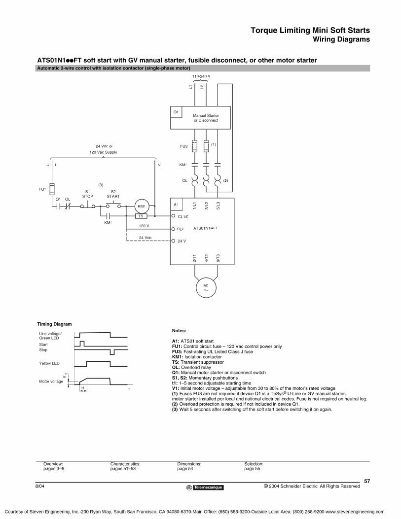
Torque Limiting Mini Soft StartsWiring Diagrams
578/04 © 2004 Schneider Electric All Rights Reserved
ATS01N1ppFT soft start with GV manual starter, fusible disconnect, or other motor starterAutomatic 3-wire control with isolation contactor (single-phase motor)
Timing DiagramNotes:
A1: ATS01 soft startFU1: Control circuit fuse – 120 Vac control power onlyFU3: Fast-acting UL Listed Class J fuseKM1: Isolation contactorTS: Transient suppressorOL: Overload relayQ1: Manual motor starter or disconnect switchS1, S2: Momentary pushbuttonst1: 1–5 second adjustable starting timeV1: Initial motor voltage – adjustable from 30 to 80% of the motor’s rated voltage(1) Fuses FU3 are not required if device Q1 is a TeSys® U-Line or GV manual starter.motor starter installed per local and national electrical codes. Fuse is not required on neutral leg.(2) Overload protection is required if not included in device Q1.(3) Wait 5 seconds after switching off the soft start before switching it on again.
Overview:pages 3–6
Characteristics:pages 51–53
Dimensions:page 54
Selection:page 55
KM1
KM1120 V
24 Vdc
M11~
Manual Starteror Disconnect
Q1
L1 L2
120 Vac Supply
STOP
FU1
OLQ1
L+
STARTS1 S2
FU3
KM1
OL
N-
(2)
(1)
110-240 V
6/T
3
4/T
2
2/T
1
ATS01N1••FT
24 V
CL2
1/L1A1
CL1/05/
L3
3/L2
24 Vdc or
(3)
TS
t1
V1
Line voltage/Green LED
Yellow LED
Motor voltage
StartStop
t
Courtesy of Steven Engineering, Inc.-230 Ryan Way, South San Francisco, CA 94080-6370-Main Office: (650) 588-9200-Outside Local Area: (800) 258-9200-www.stevenengineering.com
Torque Limiting Mini Soft Starts
© 2004 Schneider Electric All Rights Reserved58
8/04
Courtesy of Steven Engineering, Inc.-230 Ryan Way, South San Francisco, CA 94080-6370-Main Office: (650) 588-9200-Outside Local Area: (800) 258-9200-www.stevenengineering.com
Torque Limiting Mini Soft Starts
598/04 © 2004 Schneider Electric All Rights Reserved
Courtesy of Steven Engineering, Inc.-230 Ryan Way, South San Francisco, CA 94080-6370-Main Office: (650) 588-9200-Outside Local Area: (800) 258-9200-www.stevenengineering.com

Catalog No. 8637CT0401 August 2004 © 2004 Schneider Electric All Rights Reserved
Schneider Electric USA8001 Highway 64 EastKnightdale, NC 275451-888-SquareD(1-888-778-2733)www.us.SquareD.com
Schneider Electric Canada19 Waterman Avenue, M4B 1 Y2Toronto, Ontario1-800-565-6699www.schneider-electric.ca
Altistart® 01Soft Starts
Courtesy of Steven Engineering, Inc.-230 Ryan Way, South San Francisco, CA 94080-6370-Main Office: (650) 588-9200-Outside Local Area: (800) 258-9200-www.stevenengineering.com