altivar 28 telemecaniquefile.yizimg.com/325431/2009021302401223.pdf · =altivar atv-28h !"# !...
TRANSCRIPT

Altivar 28Telemecanique
!
!"#$%
Building a New Electric World

! 3 IT !"#$%&'#$()*+EMC !"#
!"#$%&
!"#$%&'() !"#$%&'()*+#,-
!"#$ !"#$%&'()*+,-./01234567.8 !"
!"#$% !
!"#$%&'()*+, !"#$ALTIVAR !"# LED
!" 10 !"#$%& !"#$
!"# !"#$%&'($)*+,- !"#$%&'()*+,-./0
!"#$%&'()*+,-. !"#$%&'()*+, !"#$%
!"#"$%&' !" !"#$%&'()* !"#$ %&'(
!" !"#$%&'()*+ !"#$%&'()*+',-./0
!"#$%&'()*+,- !"#$%&'()*+,-.
!"#$%&'()*+,-./ !"#$%&'()*+#,-
!"#$ %&'(#)*+,-.
!"#$%&'()*+,-'./$012345'678
!"#$%&'IEC !"#$% !"#& !"#$%&'()*+,
EMC !"#$%&'()*+,- !EMC !"#$%
ATV 28 !"#$%& !"#$%&'()*+,-./0 !"#EMC
! !"#$%&'()*+,-./"012

1
Altivar 28 !"#$%
50
2

2
!"#$
!"
!"
!
I/O !"
!"#$
!"#
!"# !
JJ
L
3
4
5
7
10
17
18
25
26
28
29
30
38
44
45
48

3
1 - != !"#$%&'()*+,-./01%23/$"4%)*567
= !"ATV 28 !"#$%&'()*+,-
2 - !"# !( 4 )3 - ! "#$%&' "()*+,( 56 )
4 - !"= = !"#$%&'(= !"#$= ! !"#$
5 - !"# !"#6 - = !"#$% bFr ( 50Hz )= !"#$%&'()*+,-./ ! I/O drC !"
7 - !"!#$% !"#$%&'( (ACC) (dEC) !"# ! (LSP HSP) !"#$ (ltH) !"#$%&' ( !"
8 - !" !"# 44 !"#!$%&
!"#$
! "#$%& "'()* !"#$%&
!= !"#$%&'( !"#$%&'()*+,- ! 44 !"#$%&'(= drC FCS !"#$%&'( ! yes !"# 33
!"#$%&'()*+,-.

4
!
!"
Altivar 28 !"#$%&'()*+ ,(
!"#$ !"# !" !"
!"#$%50Hz !"230V 400V !" 3s 0 Hz 50 Hz !"#
!"#$%&'()*#
!"#$%&'( 0.7 !"#$%&'0.5s !"#$ !"#$%&'
!"#$%&' !"#$%&'(
!" 4 kHz !"=Ll1, Ll2 !"2 =Ll3, Ll44 !"(0 Hz, 10 Hz, 15 Hz, 50 Hz) !"=Al1 (0 + 10 V)W= !=Al2 (0 + 10 V)AIC (0, 20 mA)W=Al1
!R2= !"#$
!" AO (0 - 20 mA)= !"
!"#$%&'()* !"#$%&'()*+,-.
!"#$%&'()*+,-.= = 3 !"#$%&'()*+,-. !"#$%& !"#$%&'()*+

5
!"
!(1) U1...U2: 200...240 V 50/60 Hz
= Altivar 28=
=(2) (3)
U1 U2 Isc (4)
=kW HP A A kA A A W=0.37 0.5 7.3 6.1 1 3.3 3.6 32 ATV-28HU09M2=0.75 1 9.8 8.2 1 4.8 6 45 ATV-28HU18M2=1.5 2 16 13.5 1 7.8 10.9 75 ATV-28HU29M2=2.2 3 22.1 18.6 1 11 15 107 ATV-28HU41M2
!(1) U1...U2 : 200...230 V 50/60 Hz
=3 - 17.6 15.4 5 13.7 18.5 116 ATV-28HU54M2=4 5 21.9 19.1 5 17.5 24.6 160 ATV-28HU72M2=5.5 7.5 38 33.2 22 27.5 38 250 ATV-28HU90M2=7.5 10 43.5 36.6 22 33 49.5 343 ATV-28HD12M2
!(1) U1...U2 : 380...500 V 50/60 Hz
= Altivar 28=
=(2) (3)
U1 U2 Isc 380V 500V (4)
-460V
=kW HP A A kA A A A W=0.75 1 3.9 3.5 5 2.3 2.1 3.5 33 ATV-28HU18N4=1.5 2 6.5 5.7 5 4.1 3.8 6.2 61 ATV-28HU29N4=2.2 3 8.4 7.5 5 5.5 5.1 8.3 81 ATV-28HU41N4=3 - 10.3 9.1 5 7.1 6.5 10.6 100 ATV-28HU54N4=4 5 13 11.8 5 9.5 8.7 14.3 131 ATV-28HU72N4=5.5 7.5 22.1 20.4 22 14.3 13.2 21.5 215 ATV-28HU90N4=7.5 10 25.8 23.7 22 17 15.6 25.5 281 ATV-28HD12N4=11 15 39.3 35.9 22 27.7 25.5 41.6 401 ATV-28HD16N4=15 20 45 40.8 22 33 30.4 49.5 543 ATV-28HD23N4

6
!"
(1)= ! " U1 U2
(2)= !"#$%&'()! 4 kHz !" !"#2-15 kHz 4 kHz !"#$% !"#$%&'()*
=12 kHz ! 10%=12 kHz ! 20%
(3) 4 !" !"# 4 kHz !"# !"#$%&
(4) 60 s
(5) !"#$%&' Isc !"#$%& !"#$% !"#$%&

7
!"
2Ø
G
H
= = ==
4Ø
H=
=
G= =
ATV-28H a b c G H 2Ø 4Ø
U09M2, U18M2 105 130 140 93 118 5 1.8
U29M2, U18N4, U29N4 130 150 150 118 138 5 2.5
U41M2, U54M2, U72M2, U41N4, U54N4, U72N4 140 195 163 126 182 5 3.8
U90M2, D12M2, U90N4, D12N4 200 270 170 180 255 6 6.1
D16N4, D23N4 245 330 195 225 315 6 9.6
mm mm mm mm mm mm mm kg
!
!"#$ 10 !
!"#$%&'
!"#$%&' !"#$%&'(&)*+,-.

8
!"#$
!"#$%&' 10mm
=-10 40=d 50 mm !"=d 0 !"#$%& !"#$ !"# !"# IP20==40 50=d 50 mm !"#$ !"# IP20
!" ! 40 1 !"#$%&" 2.2%=d 0 !"#$ !"# IP20
!" ! 40 1 2.2%==40 60=d 50 mm !"#$ !"# IP20
!" ! 50 1 !"#$%&" 3%
9
!"
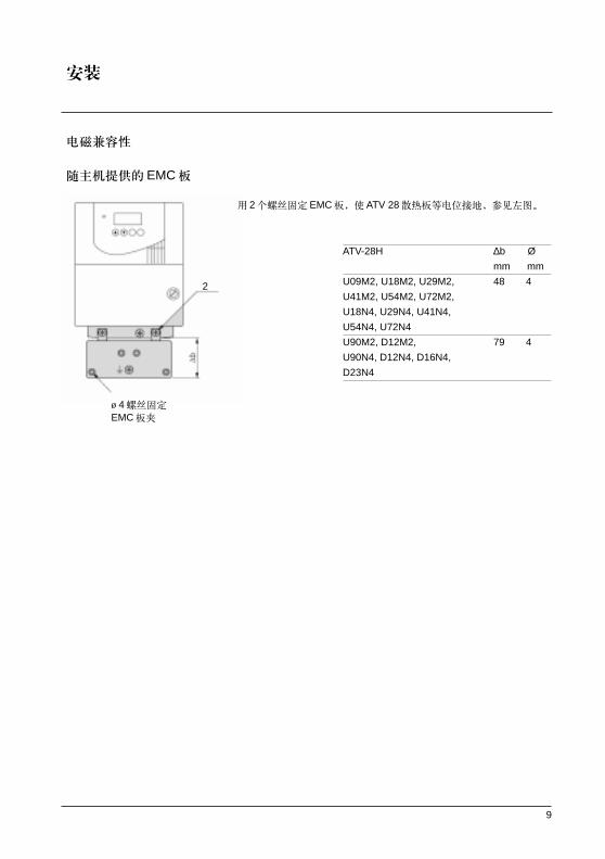
!"#EMC
2 !" EMC ATV 28 !"#$%& !"
ø 4 !EMC
2
ATV-28H ∆b Ø
mm mm
U09M2, U18M2, U29M2, 48 4
U41M2, U54M2, U72M2,
U18N4, U29N4, U41N4,
U54N4, U72N4
U90M2, D12M2, 79 4
U90N4, D12N4, D16N4,
D23N4

10
!
!"#$% !" !"
ATV-28HU09M2
!"#$%&'()*+,
!"#$%
!"#$ !"#$%
1 2 !"1 2 !"#$%&'()3 !"#$%& !"#$
!
!"#
=Altivar ATV-28H !"# !Nm
AWG mm2
U09M2, U18M2 AWG 14 2.5 0.8
U29M2, U18N4, U29N4 AWG 12 3 1.2
U41M2, U54M2, U72M2, AWG 10 5 1.2
U41N4, U54N4, U72N4
U90M2, D12M2, AWG 5 16 2.5
U90N4, D12N4
D16N4, D23N4 AWG 3 25 4.5
11
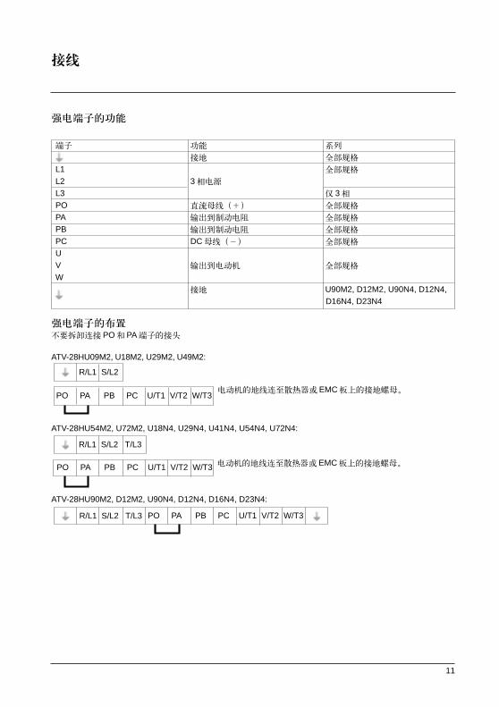
!"#$
= = =
= = !
=L1 = !
=L2 =3 =L3 = 3
=PO = ! = !
=PA = !"#$ = !
=PB = !"#$ = !
=PC =DC = !
=U=V = !"# = !
=W= =U90M2, D12M2, U90N4, D12N4,
D16N4, D23N4
!"#$ !"# PO PA !"
ATV-28HU09M2, U18M2, U29M2, U49M2:
!"#$%&'()EMC !"#$%
ATV-28HU54M2, U72M2, U18N4, U29N4, U41N4, U54N4, U72N4:
!"#$%&'() EMC !"#$%
ATV-28HU90M2, D12M2, U90N4, D12N4, D16N4, D23N4:
R/L1 S/L2
PO PA PB PC U/T1 V/T2 W/T3
R/L1 S/L2 T/L3
PO PA PB PC U/T1 V/T2 W/T3
R/L1 S/L2 T/L3 PO PA PB PC U/T1 V/T2 W/T3

12
!
!"#$% !"
!"#$
====1.5mm2 - AWG 16 !"#$
====0.5 Nm
==== !
R1A R1 !"C/O ==== !"#
R1B RIC ==== =10 mA, 5 V
R1C ==== !"#$%&'(
R2A R2 !"#$ ====(cosφ = 0.4 , L/R = 7 ms):
R2C ! ======= =1.5 A, 250 V 30 V
COM I/O
Al1 !"# ======= ! 0 +10 V ( !"# 30 V/min, ! -0.6 V)= 30 kΩ= 0.01 V= 4.3% ! 0.2%
= !" 5 ms
+10 1 -10 kΩ !"# +10 V (+ 8%-0), 10 mA !"#$%
Al2 !"# ==== ! 0 +10 V 30 kΩ
AlC !"# ==== ! X-Y mA. X v 0-20 mA 250ΩAl2 AIC
!"#$ ! ! Al2 AIC = Al1
AO ! ==== MJOM=ã^ QJOM=ã^
==== = !" 6% !"# 500ΩLl1 ! ==== !"#$
Ll2 ==== =+ 24 V (max. 30 V)
Ll3 ==== = 3.5 kΩLl4 ==== =< 5 V, 0 X=> 11 V, 1
==== = !"# 9 ms
+24 !"# ====+24 V !"#$%& 19 V
==== 30 V !"# 100 mA

13
!"
!
!
!"
(1)= !"=( !)
(2)= !"#$% !"#$%&'
(3)=+24 V !" ! +24 V 0 V !"COM () !"#$%
+24 V
!"#$%&'() * !"#$%&'( ! !"#$%&'()
!
Altivar 28
!
24 V

14
!"#
!
!"#$%&'(
!"#$%&'((> 3.5 mA) !"#$% !" !"#$% !"#$%& B ! !"#$%&'()*+, !"#$%&'()*+,-./ !" !"#$% !" !"#$% !"#$%
!"#$%&'()*#+,#$ !"PLC !" !"#$%
!
!"#$%&'() !"#$%&'() !"#$%&'()25-50mm !
!"#$%

15
!"
= ! !"#$%&'()*+,-.= ! !"#$%&'()*+ ,- !"#$ 360 ! !"#$%&'= !"#$%= ! "# $ "%&'()*+
16
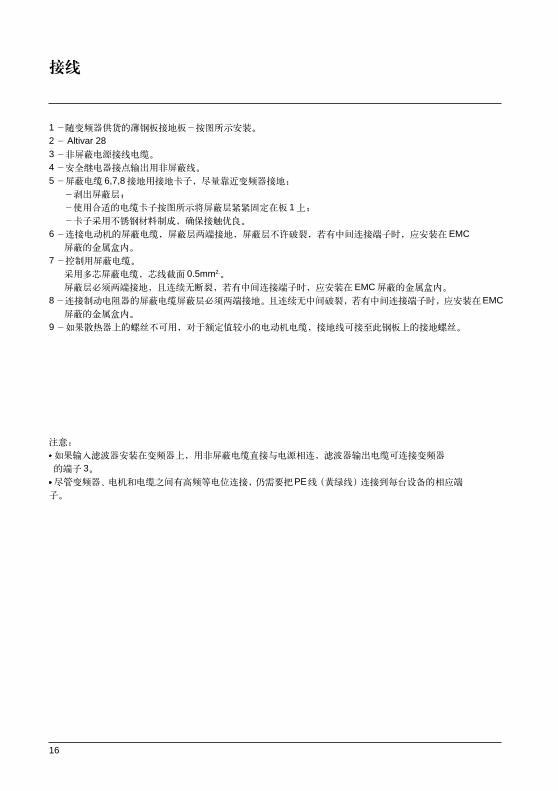
1 !"#$%&'()*(+,-./012 Altivar 283 !"#$%"&'4 !"#$%&'()*+,-5 !" 6,7,8 !"# !"#$%&W
!"#
!"#$%&'()*+,-./001234 1
!"#$%&'()* !"#$
6 !"#$%&!'( !"#$% !"#$% !"#$%&' ! EMC !"#$%
7 !"#$%& !"#$%& ! 0.5mm2.
!"#$%&' !"#$ !"#$%&' ! EMC !"#$%8 !"#$%&'(#)'(*+,-. /0 !"#$%& !"#$%&' !EMC !"#$%
9 !"#$%&'()*+ !"#$%&'(&)* !"#$%&'()*
= !"#$%&'()$*+ !"#$%&"'()* !"#$%&'()
= 3= !"# !"#$%&'()*+ !PE !" !"#$%&'(

17
!
!"#
!"#$%&'( !"#$% ! 1 C/O !"#
!"#$%&' !"#$
!"#$%&'()* LED !"
!" # !"#$ !"#$
! !"# !"#$%&'()*+
!"#$%&
!"#$%&'!()*+,-#./012345
!"#$%&'()*+,- !"#$
!" 185% !"#$%&2 s !"#$%&'()*+,"60 s
!"
!"#$ !"#$%&' !"#$ !"#$%&'( !"< 0.5 Hz ! !
!"#
! I2 t !"#
!"#$ !"#$%&'

18
I/O !"
!"#$%
! L
!"#$%&'( !"#$%&
! 1WACCdEC 2WAC2dE2 !"#$%&'
- !"# L1x- !"#$% Frt
EJOGFW !"# !"#$% !"#$%&'( !0.1 s ( ACCDECAC2DE2 )
!"#$% !"#$ !"#$%&'
2 !"#$%&'($) 0.5 s !"#$ !W
!"
3 !
2 !"#$%&'()*+ !" # !LI1 !"#$% !" 0 !"#$% !"#$%&
!"#$%& '()*+, !"# !" ! !"#$% !"#$
2 ! !"#$%&1 ” =0 !"#$ !" # !
! !"#$%&'()* ! ! !"#$% !"#$%&'#(
!"#$%"&'(drc ! Art ! !"#$%&'()*+

19
I/O !"
!
2,4 8 ! !"#$ 1,2 3 !"#$%
!"#$%&'PS2 (LIx) PS4 (LIy) PS8 (LIz)
2 !" ===4 !" ===8 !"Llx PS2 ===Llx PS2, Lly PS4 ===Llx PS2
===Lly PS4, Llz PS8Llx== ! ===Lly Llx== ! ===Llz Lly Llx == !
0====(min = LSP) 0 0 (min = LSP) 0 0 0 (min = LSP)
1 HSP 0 1 SP2 0 0 1 SP2
1 0 SP3 0 1 0 SP3
1 1 HSP 0 1 1 SP4
1 0 0 SP5
1 0 1 SP6
1 1 0 SP7
1 1 1 HSP
!"#$%& !"#$PS8 (LIz)PS4 (LIy)PS2 (LIx)
!
!"#$%& 2 Al1 Al2 AlC ! !"# AI2 AIC !"# 2
!"Z=Al2AIC
!"Z=Al1Al2/AlC PI = !"2
!" 22 F

20
I/O !"
!
!" !"#$%
!"#$%&'() !" 0 !"#$
!"#
2
1F= !"#$%&'( < 0.5 Hz !
!
!" !"#$% !"#$%& 4
!"#$%&'()*+,-. 0F !"#$ !"# !"#
!
!"#$ !"# !"#$%&'()*
!"#$OCF !SCF !"#$EEF !"# INF !"# !"#$% !"#0 !1 !"#
!"#$%&'(
!"#$ !" !"#$ !"#$%&

21
I/O !"
!"#$%
AI1 !"#
AI2/AIC=(AI2 = 0, +10 VAIC = X-Y mA, XY = 0-20 mA)
!"#AI2/AIC !"# AI1
PI !AI2/AIC !"#$%& PI !
PI !" I/O ! AIC PI !"#$%&'()*
AIC=PIAAIC PI AI1 !"#$AI2AIC !"#$PI !"# !"#$
! !"#$%&'()
AIC=PII !"#$% rPI !"#$%&' !"#AI2 AIC !" !"#$ !
!"#$rPG
!"#$rIG
PI !"#FBS !"#$%&'()*+, PI !"#$%&'()* !"#PIC PIC=no !" #$ !"#$% !"#$
PIC=YES !" #$%&'()*+ !"#$%&'()*
CrL CrH (I/O !)
22
I/O !"
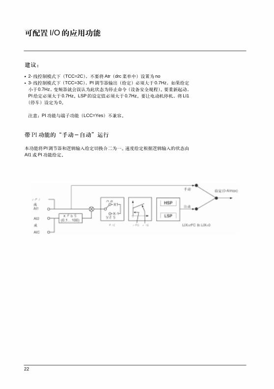
2- !"#TCC=2C Atrdrc ! no3- !"#TCC=3CPI !" ! ! 0.7Hz !0.7Hz !"#$%&'(%)*+, !"#$%& !"#PI !"# 0.7HzLSP !"#$% 0.7Hz !"#"$ LI1 ! 0
PI !"LCC=Yes !
mf !" #
!PI !"#$%&'()*+,-. !"#$%&'()*+AI1 PI !"

23
I/O !"
R2 !"#$
!"#(FtA) !"#$%&'()* Ftd !"#$%&'()*+,-
!"#$(SrA) !"#$%&'()*+,-./0
!"#(CtA) !"#$%&'(Ctd !"#$%& !"#$%
!"(tSA) !"#$%&'()!*+"#,-./012345
!AO !
! AO !"# ! 0-20 mA 4-20 mA
!( OCr) !" #$%&'()*20 mA 2 !"#$%"&' 1th
!" ( rFr) !"#$%&'(!)*+20 mA !"#$ rFr
!" ( OLO) !"#$%&'()*+20 mA 2 !"#$%&'
( OPr) !"#$%&'()*+,20 mA 2 !"#$%&( )

24
I/O !"
!" !"#$% I/O !"#$%&'()*+,- !"#$%&'()*+$,
!"#
!
PI
!
!
!
JOG
!
!"#
!
PI
!
!
!
JOG
!
!"
!
N/A
!" !"#$%& '
!"#$%&'()*+#$
!"#$%&'()*+
!"#$%&'($)*+,-./0$)

25
!"#$
!"#$%&
!"#$%0 !"#$ !"#$%&'()*+,- !"#$%
!"#$
!"#$%&'(
!"#$ KM1 !"#$%&'()*
LI1-LI4 !"
!"#$%& 60 s !"#$%&'
!"#$%&
! !"#$%&'()* !"#$ !"#$%&'()*drc
FCS YES 3
!"#
!"#$
!"#$ !"#$%&'()* !"#$
!"#$%&'()*+,-.
!"#$%&'()*
!"#$#%&'()*+,#%-./0 4 ! "#$%&'()*+
!"
!"#$%&'()*+,-./0*123456 !"# ! !
!"# !"#$%&' !"#$%&'( !"#rdY !"#
!"#$%#&'drc ! Atr ! 35 !"#$%&'
!"#$%!"#&'
!"#$%& !"#$%&'(OPL=YES !"#$%&'()*+,-
!"#$%&'()*+,-. !"#$%&'()*+,-.OPL=no !
!"#$%&'

26
!"#
= LED
DC !"= !"#$%&'(
!
=4 7
= !"#$%
!"#$
= !"#$%&'%()*+, = !"#$%&' !"#$%&'(
!"#$
============ !"#$
!"#$
!"#$% !"
! !" !
Init !"
rdY !"#$
43.0 !"#
dcb !"#
rtrY !"#$
nSt !"#
FSt !"#

27
! !"#$%&'
!"#$
50 Hz !"#$ 60 Hz
!"#$
3 s
ups
!"SEt-drC-I-O-
!"#$%&'( !"#$%&'
PC !"#$%&'()*
SUP 40
!
!"
!
1
!
(1)= !"#$ bFr !"#$%
!"#$ bFr !"
28
!"#
!"#$%&'() !"#$%& 2 !" !"#$%&'(")
RUN !"#$ !"SEt- rOt !"#$%&
STOP/RESET !"#$% !" !!"#$ !"#$% !"#$%&'
!!"# !"#
!"#$%&'() AI1
!"#$%&'()*'+,-./0
===== =I/OW-tCC = OPt !"
-LI1 = no !"
-LI2 = PS2 !
-LI3 = PS4 !
-LI4 = PS8 !
=Atr = no YES !
!"#$% !"#
!"#$%&'()*+, !" InF !"

29
!"#$%
!"#$%&'()&*+,-./ !"#$%&'$!()*+" !"#$%&' !
!"#$ATV 28 !"# !"#$% 3 !"#$ !"#
=FWD/RV !=RUN !"#=STOP/RESET !"#$%&'( !!"#$%&'()*+ !" #$ !!"#$%&'()
4
!
!"#$
!"#
===
bdr 19.2I/O 46

30
I/O ! !"#$%&'()*+,
! I/O !"#$%&!"'
==== !"
!"#$2 ! 3 =====2C2C = 2 3C= 3 OPt = !"#$% 3
2 W !"#$%&'()*+#,-
!
LI1
LIX
3 !"# !"#$% !
LI1
LI2
LIx
tCC ! !"#$% !"
=tCC = 2C : LI1 : !" !" =====LI2 : rrS= !"#== LI3 : PS2 =====LI4 : PS4
=tCC = 3C : LI1 : ! !" LI2 : For !"# !"= LI3 : rrS !"# LI4 : JOG
=tCC = OPt : LI1 : !" ======LI2 : PS2= LI3 : PS4 ======LI4 : PS8
- L C C !"#$%&'()*+no-YES =====no
!"#$% STOP/RESET, RUN FWD/REV !"#$% SEt LFr !"# !"#$ !" !"#$ !"#$ ! L !"#$%& !"#$ SLF

31
I/O !===========
= ===== !"
- L I 2 ! =====rrS- L I 3 no =====PS2- L I 4 rrS ! !"# =====PS4
rP2 !(1)JOG !(1)PS22 !PS44 !(1)PS88 !(1)nSt !" !"#$%&dCI ! !"# !" # !===== 0.5=ItH, 5 s
FSt !" !"#$%FLO !"#
rSt !rFC ! !"#AIC/AI2 P1 !"#$%&= tCC=3C L12= !"= !"#$%&'()* !"#$=ENT != !"#$ 4 8 !"PS2, PS4, PS8 !"#$%&'()== ! !"# I/O !"
- A I C ! AIC/AI2 SAIno SAI A1
PIIPI !"PI !"#$%& rPI (1)PIAPI !"PI !" AI1 (1)=SAI !"#$%&' rFC !"=PII PIA ! !"#$%& LOG PS2= !"#$ LIX rFC !"# AIC ! PII PIA== AI1 !"#(L1x=o) L1x=1 !"# PI
(1) !"#$% SET !"#$%&' !"#$

32
I/O !===========
==== !"
- C r L AIC !"#0-20 mA =====4 mA- c r h AIC !"#4-20 mA =====20 mA
2 !"#$%&' 0-20 mA, 4-20 mA, 20-4mA
A12 ! !"#$%&
4 mA 2 V20 mA 10 V 0-10V CrL 0 CrH 20 !"# PI !"#$%&
- a o ! =====rFr
no !OCr !20 mA 2 !"# $ ItHrFr !"#20 mA !"#$ tFrOLO !"#20 mA 2 !"#$%&OPr !"#$%20 mA 2 !"#$%&
- A o ! =====00 : 0-20 mA4 : 4-20 mA
33
I/O !===========
= ===== !"
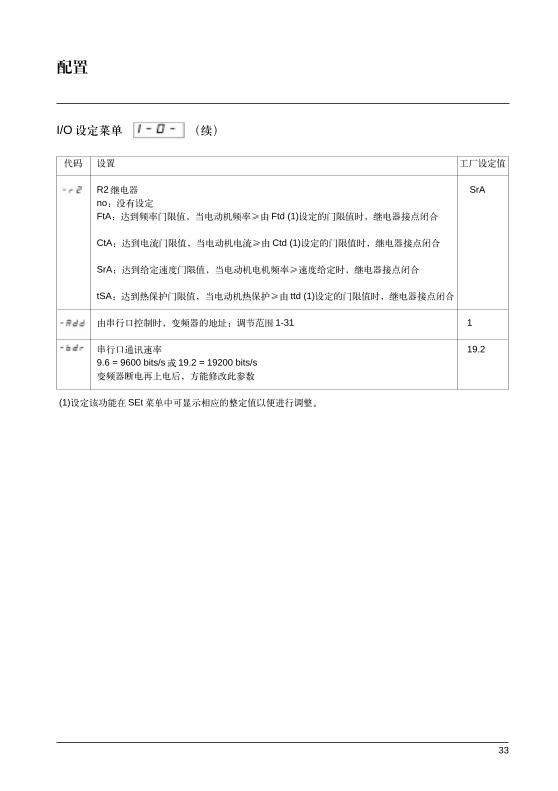
R2 ===== SrAno !FtA !"#$% !"#$% Ftd (1) !"#$% !"#$
CtA !"#$% !"#$Ctd (1) !"#$% !"#$
SrA !"#$%&' !!"#$%&'()* !"#$
tSA !"#$%& !"#$%& ttd (1) !"#$% !"#$
- a d d !"#$% !"# ! 1-31 ===== 1
!"#$ ===== 19.29.6 = 9600 bits/s 19.2 = 19200 bits/s !"#$"%& !"#$
(1) !"# SEt !"#$%&'()*+,-.'/

34
!
!"#$%&' !"#$ Frt, Sfr, nrd SdS !"#$%
!"#$%
J !"#$%
J !"#$E !"#$%F
===== !========
=====
!"#$%&'()
!"#$%
ATV28 = = = =M2 =====200 240 V== 230 VATV28= = = = =N4 ==== 380 500 V== 400 V ;
=====bFr = 50=====460 V ;=====bFr = 60
!" =====40 400 Hz== 50/60 Hz
===== bFr =====no-donE-YES no V/F n nLdUft - noIEC !"#$%&'()- donE !"#$%& !"#$%&'(- YES !" !"# rdY !"# tUn, donE tnF !"#$%&'()* !"# !"#
L P Uft ! !"#$%&'()*+,-. !"#
!"#$%&'()*+, !"#$%1
0 !"#
!"# =====40 400 Hz=====60/72 Hz (1.2 x bFr)

35
!=============
!=====
=====
L L - P - n - nLd n- L !"#$% - P !"#$
- n !"# !"#$%&'- nLd !"#$%&'()!*+ !" !"#$%&'()*+,-./ !"#$%& no=J=YES====YES !"#$%&'( obF no !"#YES !" !"#$%&'()*+,)-./()01234
!"# 0 HSP=====0 Hz !>Frt !"#AC2 dE2 Frt = 0 !"# !"#$%&'()*+, rp2 !"#$%
! 2 15 kHz===4.0 !"#$% !"#$%&'(
4 kHz !"#$%&'(
12 kHz 4kHz !" 1kHz ! 1.25%12kHz ! 10%
12 kHz !" 1kHz ! 10%+3.3%15kHz
! 9.9%
!"#$%&'()* !"#$%no: !" no-YES =====YESYES: !
!"#$%&

36
!=============
!=====
=====
!"# !" !"#$ !"#$% no - YES - no !"# !"#$%&'() !"#$%&'()*+ USF !" 1 s, 5 s, 10 s 1min 6 min !"#$% !"#$ !"# !"#$%!&
!"#$%&'(OHF, OLF, USF, obF, OSF, PHF, OPF, SLF !"#$%& !"#$%!&'()*
!"#$%&'() !"#$ 2 EtCC= 2c) !
!"#$%&'()*+,-./0123456
- no !
-YES !
-USF USF !"
- o p l !"#$ no - YES YES
YES !====== no !
OAC !"#$%&'()*+,-.%,/0
- I p l !"#$% no - YES YES
no !==YES !
ATV28HU09M2, U18M2, U29M2
U41M2 !"# !
!"#$ !"#$ MK7 !"# ! !"#$%
- s p ! no - YES no
!"# !"#$% !"#$% !"#
!
no !==YES !
37
!=============
!=====
=====
!"# !"#$ !"#$% no -YES===== no !"
!"#$%&'%
!"# !"#$%&'#(
no !==YES ! !"#$ 40% ! USF !"# no - YES==== no
no !
YES !
= !"#$%&= !"#$ !"#$%
!"#$%&'SPd !"#$%&' ! 1-200 30 !"#
4 !1500 rpm, 50 HzJSdS = 30JSPd = 1500 (50 Hz)
- f c s !" no - YES==== nono : noYES: !"# InIt bFr !"#
!"#$%&

38
!
!"#$%&'()*+,-./01 !"#$%&'()
!"#$%&'()
!======
======
- l f !"#$%&'() LSP HSP !"#$%&'()*+,- I/O ! LCC !"#$%
- p i PI 0.0 100.0%= 0.0 ! AIC/AI2 !"PI AIC=PII, !"rPI !"#AI !"#$%&' !"AImax
AI2 !"# AIC !"#$ I/O !CrL CrH !"
(AIC x FbS) - CrLrPI=100 CrH - CrL
AIC x FbS 10 !"#$AIC 4-20mA 10mA
10-4rPI=100 =37.5
20-4
- o ! For rrS For !"#$%& !"#
!"#$
forward: For reverse: rrS
(1) In !"#$%&' !"#$%&'()*+
!"#$%&' drC I-O !"#$%&'()*+,-

39
!==============
(1) In !"#$%&' !"#$%&'()*+
!"#$%&' drC I-O !"#$%&'()*+,-
!=====
=====
- A C C !"#$% 0,0 3600 s 3 s- E C ! 0 !" bFr !" dEC !"#$%&' 0.0 3600 s 3 s
- A C 2 2 !"#$ 0,0 3600 s 5 s
- E 2 2 !"#$ 0.0 3600 s 5 s !"#$%&'()drC ! Frt 0Hz
!"#$%&'()*+,-./
- L S P 0 HSP 0 Hz- H S P !"#$%&'!()* LSP tFr bFr- I h !"#$%&'( !"#$%&'() *+ 0,20 1,15 In (1)
!"#$%&'()*+( ntH In (1)- U f !"#$%& 0 100%=====20
U f !" !"#$%&'(
- S L P !"#$%&'()*+ ,-./ 0.0 5.0 Hz ! drC !UFt = n !"#$%&'( =====

40
!==============
!
- f l g !"# brA=YES !"#$ 0 100% 33 !
!"# !"#$%&!OBF !"# !"#$%&'( ! FLG !"#$%&'(
!"#$%&'OBF !"#$%&'()*- i c DC !"# 0.1 ItH 0.7 In (1)
!"#$%&'()5 !"#$% 0.5 Ith In (1)- c DC !"#$ 0 25,4 s 0.5 s
!"#$ 25.5 s !"#Cont !"#$
!"#$
- J P F !"# JPF 2Hz !"#$% !"#$%& 0 HSP 0 Hz !"#$%& 0 !"#$
- j o g !"# 0 10 Hz 10 Hz- p g PI !"#$%PI !"#$%&'()*+ 0,01 100 1- i g PI !"#$%PI !"#$%&'()*+ 0.01 100/s 1/s- f g PI !"# 0.1 100 1- p i c PI !"#$%& no YES no
no YES
(1) In !"#$%& !"#$%&'
!"#$%& drC I-O !"#$%&'()*
41
!==============
(1) In !"#$%& !"#$%&'()
!"#$%& drC I-O !"#$%&'()*
!=====
=====
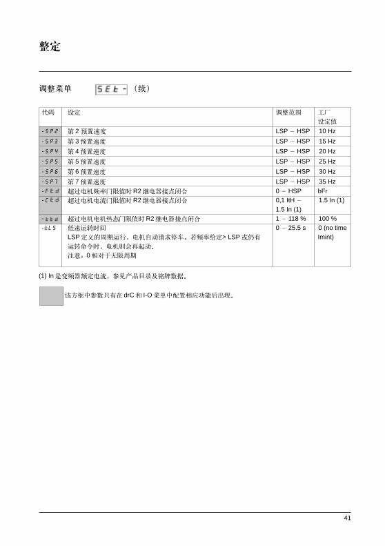
- s p 2 2 ! LSP HSP 10 Hz
- s p 3 3 ! LSP HSP 15 Hz
- s p 4 4 ! LSP HSP 20 Hz
- s p 5 5 ! LSP HSP 25 Hz
- s p 6 6 ! LSP HSP 30 Hz
- s p 7 7 ! LSP HSP 35 Hz
- f !"#$%&'R2 !"#$ 0 HSP bFr- c ! "#$%&R2 !"#$ 0,1 ItH ==== 1.5 In (1)
1.5 In (1) ! !"#$%&'R2 !"#$ 1 118 % 100 %
- l s !"# 0 25.5 s 0 (no timeLSP !"#$% !"#$%& !"> LSP =====Imint) !"# !"#$%
0 !"#$
42
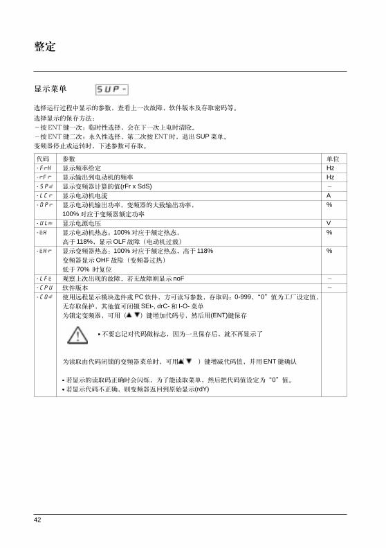
!
!"#$%&'()* !"#$% !"#$%&'(
!"#$%&
bkq !"# !"#$%&'(
bkq !"# ! bkq SUP !"#$%&' !"#$%
=
- F H !"# =Hz- F !"#$%&'( =Hz- s p !"#$%&(rFr x SdS) =
- l c !" # =A- d p !"#$%&' !"#$%&'( =%
100% !"#$%&'- u l ! " =V- h !"#$100% !"#$% =%
118% OLF !"#$
- h !"#$100% !"#$% 118% =% !"OHF !"#$
70%
- l f !"#$%&' !"#$ noF =
- c p u ! =
- c o !"#$%&'( PC !"#$ 0-9990 !"#$ !"# !"# SEt-, drC- I-O-
!"#$==== !"#$ (ENT)
=== = !"#$%&'( !"#$% !"#
!"#$%&'()*+,-==== !"#$ ENT
= !"#$%&'()*+ !"#$% !"#$%&0= !"#$%& !"#$%&'((rdY)

43
!
JJJJ !"#$ !"#$%&
- Init !"- rdY !"#$- 43.0 !"#- dcb !"# !"- rtrY !"#$- nSt !"#- FSt !"#- MEmO !

44
!"#$%& !"#$%&#W
J !"#$%&
J !"#$%&'()* !"#$%&'()* 3-5
J !"#
!"
!"#$%&'() !"#$%&'()*+ !"#$
!"#$%&'()*+,-. !"# !"R1
!
!"#$%&'()*"+,- LED !"#$%&
!"#$ !"
!"# !"# !"#
!"#$%& !"#$%&'()*+,-.,/
!
!"#$%&'()*+, !"#$%&'!"()*
!"
!"#$%&'()*+,-

45
JJ
!"#$% !"
= !"#$%&'()* !"# !"#$% !"#$%&'(ATV-28nStFSt !"#$%&'($%)* !"0 !" !"#$%&'()*+,-.= ! ! !" !"#$ !" !"#$%&'()*+ !"#$
!"#$ !"rdY !" !"#$%&drC ! Art ! !" !"#$
!"#$%&
!"#$%&'()*+ ! !"#
- d c f !"# !"#
!"#$% !"# L L !
!" !"#$
!"#$% !"#$%&'()&*+,
- s c f !"#$%&'() !"#$%&'()*+!"#$,-!.
! !"#$%&'() !"#$
== !"#$%&'() !"#!$%
- i f !" !" !"#$
! !"#$%&' !"#$%&'()
==
!"#$%&'( L
- i f !"#$!"#%&'( L P
!" ==
!"#$%&'( !"#$%&'()*
!"#$%&'() !"#$
- e e f !" !"#$%&'( L
! !"# !"#$%&'()
EEPROM

46
JJ
!"#$%&'%()*+,-.
- d h f I2t >1.85 In 2s !"#$%&
!" ==========>1.50 In 60s !"#$%&'()*+, !"#$
!"#$% == !
- d l f !" I2t ! !"#$%&'()*+,-.
!" == !"#$%&'(
- d s f J !" !"!#
J !"
- u s f !"# !"!#$!#%&
!"#$
!"#$
- o f !" !"#$
!"# !"#$%&'(
!"#$%& brA
brA !"#$%&'J !" J ! "
J !
- p h f J !"#$%&'() J !"#$%&
!"# J !" J
J3 ATV28 !"# J 3 J !"#$ J !"#$%&
J ! J !"#$UFr

47
JJ
- O P F !"#$%& !"#$%&'()*+,
!"# !"#$% !"#$%&'( OPL OAC !"#$%& !'()* !"#$%&'()"#$ !"#
!"#$%&' (OPL=YES)
!"#$%&'()*+,-./012
!"#$%&'()* ( !"#$% !) !"#$%&' (OPL=NO)
!"#$%&' !" Ith UnSUFr !"#$%&'
- S L F !"#$%&'( !"#$%&'()*+,-./
!"# !"#$%&'() !"
!"#$!"%&
!LED ! !"#$
!
- Y LI !" !"# !"# 24V !"# LED !"#$ !"#$
!"#$%&'(- Y or s !"#$%&'( DEC FLG !
!

48
L
= L
=== !
== !" ===== !" == !" ===== !"
- u s ==== V V - f S Hz Hz- u no - f Hz Hz- u f n - a ==YES- f 0 Hz Hz - s f ==4.0 kHz kHz- YES - a ==no- o p l YES - i p l ==YES- s p no - f l ==no- no - s s ==30
== !" ===== !" == !" ===== !"
- c c 2C - l 1 2 ==rrS- l 1 3 PS2 - l 1 4 ==PS4- a i c SAI - c l ==4 mA mA- c h 20 mA mA - a o ==rFr- a o 0 mA mA - 2 ==SrA- a 1 - l 19.2
ATV-28 ..................................................................................................................................................... !" ........................................................................................................................................................... !SUP CPU ................................................................................................................... !" ........................................................................................................................................................ !"# no yes
49
L
== !"
drC I-O !"#$%&'()*+,- ./01
== !" ===== !" == !" ===== !"
- p i 0.0 % - o ==For
- a c c 3.0 s s - e c ==3.0 s s
- a c 2 5.0 s s - e 2 ==5.0 s s
- l s p 0.0 Hz Hz - h s p Hz Hz
- I H A A - u f ==20 % %
- s l p Hz Hz - f l g ==33 % %
- i c A A - C ==0.5 s s
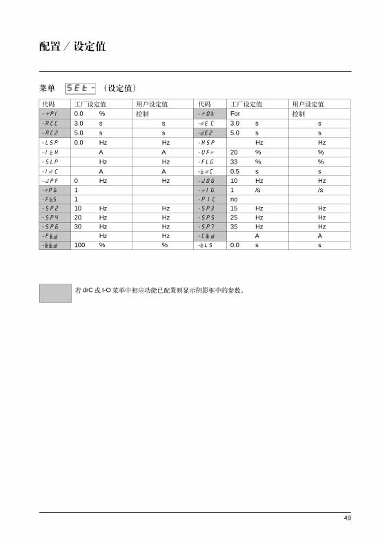
- j p f 0 Hz Hz - j o g ==10 Hz Hz- p g 1 - i G ==1 /s /s- f s 1 - p i c ==no- s p 2 10 Hz Hz - s p 3 ==15 Hz Hz- s p 4 20 Hz Hz - s p s ==25 Hz Hz- s p 6 30 Hz Hz - s p 7 ==35 Hz Hz- f Hz Hz - c A A- 100 % % - l s ==0.0 s s
50
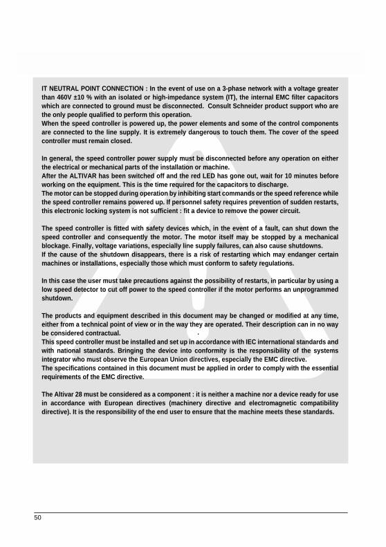
IT NEUTRAL POINT CONNECTION : In the event of use on a 3-phase network with a voltage greaterthan 460V ±10 % with an isolated or high-impedance system (IT), the internal EMC filter capacitorswhich are connected to ground must be disconnected. Consult Schneider product support who arethe only people qualified to perform this operation.When the speed controller is powered up, the power elements and some of the control componentsare connected to the line supply. It is extremely dangerous to touch them. The cover of the speedcontroller must remain closed.
In general, the speed controller power supply must be disconnected before any operation on eitherthe electrical or mechanical parts of the installation or machine.After the ALTIVAR has been switched off and the red LED has gone out, wait for 10 minutes beforeworking on the equipment. This is the time required for the capacitors to discharge.The motor can be stopped during operation by inhibiting start commands or the speed reference whilethe speed controller remains powered up. If personnel safety requires prevention of sudden restarts,this electronic locking system is not sufficient : fit a device to remove the power circuit.
The speed controller is fitted with safety devices which, in the event of a fault, can shut down thespeed controller and consequently the motor. The motor itself may be stopped by a mechanicalblockage. Finally, voltage variations, especially line supply failures, can also cause shutdowns.If the cause of the shutdown disappears, there is a risk of restarting which may endanger certainmachines or installations, especially those which must conform to safety regulations.
In this case the user must take precautions against the possibility of restarts, in particular by using alow speed detector to cut off power to the speed controller if the motor performs an unprogrammedshutdown.
The products and equipment described in this document may be changed or modified at any time,either from a technical point of view or in the way they are operated. Their description can in no waybe considered contractual.This speed controller must be installed and set up in accordance with IEC international standards andwith national standards. Bringing the device into conformity is the responsibility of the systemsintegrator who must observe the European Union directives, especially the EMC directive.The specifications contained in this document must be applied in order to comply with the essentialrequirements of the EMC directive.
The Altivar 28 must be considered as a component : it is neither a machine nor a device ready for usein accordance with European directives (machinery directive and electromagnetic compatibilitydirective). It is the responsibility of the end user to ensure that the machine meets these standards.

51
Table of Contents
Steps for Setting Up the Speed Controller _____________________________________________ 51
Factory Configuration _____________________________________________________________ 52
Speed Controller References _______________________________________________________ 53
Mounting _______________________________________________________________________ 55
Wiring _________________________________________________________________________ 58
Basic Functions__________________________________________________________________ 65
Configurable I/O Application Functions________________________________________________ 66
Setup - Preliminary Recommendations________________________________________________ 73
Programming____________________________________________________________________ 74
Local control option_______________________________________________________________ 76
Remote Display Module Option _____________________________________________________ 77
Configuration____________________________________________________________________ 78
Settings ________________________________________________________________________ 86
Maintenance ____________________________________________________________________ 92
Faults - Causes - Remedies ________________________________________________________ 93
Configuration/Settings Tables_______________________________________________________ 96
52
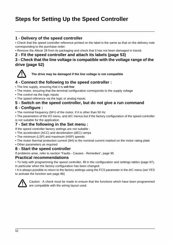
Steps for Setting Up the Speed Controller
1 - Delivery of the speed controller
• Check that the speed controller reference printed on the label is the same as that on the delivery notecorresponding to the purchase order.• Remove the Altivar 28 from its packaging and check that it has not been damaged in transit.
2 - Fit the speed controller and attach its labels (page 53)3 - Check that the line voltage is compatible with the voltage range of the drive (page 52)
The drive may be damaged if the line voltage is not compatible
4 - Connect the following to the speed controller :
• The line supply, ensuring that it is
volt free
• The motor, ensuring that the terminal configuration corresponds to the supply voltage• The control via the logic inputs• The speed reference via the logic or analog inputs
5 - Switch on the speed controller, but do not give a run command6 - Configure :
• The nominal frequency (bFr) of the motor, if it is other than 50 Hz• The parameters of the I/O menu, and drC menus but if the factory configuration of the speed controlleris not suitable for the application
7 - Set the following in the Set menu :
If the speed controller factory settings are not suitable :• The acceleration (ACC) and deceleration (dEC) ramps • The minimum (LSP) and maximum (HSP) speeds• The motor thermal protection current (ItH) to the nominal current marked on the motor rating plate• Other parameters as required
8 - Start the speed controller
If problems arise, refer to section “Faults - Causes - Remedies”, page 95
Practical recommendations
• To help with programming the speed controller, fill in the configuration and settings tables (page 97),in particular when the factory configuration has been changed.• It is always possible to return to the factory settings using the FCS parameter in the drC menu (set YESto activate the function see page 86)
Caution : A check must be made to ensure that the functions which have been programmedare compatible with the wiring layout used.
53
Factory Configuration
Factory settings
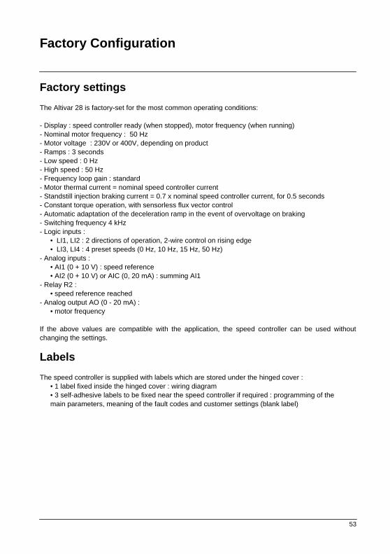
The Altivar 28 is factory-set for the most common operating conditions:
- Display : speed controller ready (when stopped), motor frequency (when running)- Nominal motor frequency : 50 Hz - Motor voltage : 230V or 400V, depending on product- Ramps : 3 seconds- Low speed : 0 Hz - High speed : 50 Hz- Frequency loop gain : standard- Motor thermal current = nominal speed controller current- Standstill injection braking current = 0.7 x nominal speed controller current, for 0.5 seconds- Constant torque operation, with sensorless flux vector control- Automatic adaptation of the deceleration ramp in the event of overvoltage on braking- Switching frequency 4 kHz- Logic inputs :
• LI1, LI2 : 2 directions of operation, 2-wire control on rising edge• LI3, LI4 : 4 preset speeds (0 Hz, 10 Hz, 15 Hz, 50 Hz)
- Analog inputs :• AI1 (0 + 10 V) : speed reference• AI2 (0 + 10 V) or AIC (0, 20 mA) : summing AI1
- Relay R2 : • speed reference reached
- Analog output AO (0 - 20 mA) :• motor frequency
If the above values are compatible with the application, the speed controller can be used withoutchanging the settings.
Labels
The speed controller is supplied with labels which are stored under the hinged cover :• 1 label fixed inside the hinged cover : wiring diagram• 3 self-adhesive labels to be fixed near the speed controller if required : programming of the main parameters, meaning of the fault codes and customer settings (blank label)

54
Speed Controller References
Single phase supply voltage (1) U1...U2 : 200…240 V 50/60 Hz
3-phase supply voltage (1) U1...U2 : 200…230 V 50/60 Hz
3-phase supply voltage (1) U1...U2 : 380…500 V 50/60 Hz
Motor Line supply Altivar 28Power indicated on plate (2)
Linecurrent (3)
Max.prosp. line Isc (5)
Linecurrent
Max. transient current (4)
Power dissipated at nominalload
Reference
at U 1 at U 2
kW HP A A kA A A W0.37 0.5 7.3 6.1 1 3.3 3.6 32
ATV-28HU09M2
0.75 1 9.8 8.2 1 4.8 6 45
ATV-28HU18M2
1.5 2 16 13.5 1 7.8 10.9 75
ATV-28HU29M2
2.2 3 22.1 18.6 1 11 15 107
ATV-28HU41M2
3 - 17.6 15.4 5 13.7 18.5 116
ATV-28HU54M2
4 5 21.9 19.1 5 17.5 24.6 160
ATV-28HU72M2
5.5 7.5 38 33.2 22 27.5 38 250
ATV-28HU90M2
7.5 10 43.5 36.6 22 33 49.5 343
ATV-28HD12M2
Motor Line supply Altivar 28Power indicated on plate (2)
Linecurrent (3)
Max.prosp. line Isc (5)
Linecurrent
Max. transient current (4)
Power dissipated at nominalload
Reference
at U 1 at U 2 at 380 to 460V
at 500V
kW HP A A kA A A A W0.75 1 3.9 3.5 5 2.3 2.1 3.5 33
ATV-28HU18N4
1.5 2 6.5 5.7 5 4.1 3.8 6.2 61
ATV-28HU29N4
2.2 3 8.4 7.5 5 5.5 5.1 8.3 81
ATV-28HU41N4
3 - 10.3 9.1 5 7.1 6.5 10.6 100
ATV-28HU54N4
4 5 13 11.8 5 9.5 8.7 14.3 131
ATV-28HU72N4
5.5 7.5 22.1 20.4 22 14.3 13.2 21.5 215
ATV-28HU90N4
7.5 10 25.8 23.7 22 17 15.6 25.5 281
ATV-28HD12N4
11 15 39.3 35.9 22 27.7 25.5 41.6 401
ATV-28HD16N4
15 20 45 40.8 22 33 30.4 49.5 543
ATV-28HD23N4

55
Speed Controller References
(1) Nominal supply voltages : min. U1, max. U2.
(2) These power ratings are for a maximum switching frequency of 4 kHz, in continuous operation. Theswitching frequency is adjustable from 2 to 15 kHz.Above 4 kHz derate the nominal speed controller current. The nominal motor current should not exceedthis value :• Up to 12 kHz derate by 10%• Above 12 kHz derate by 20%
(3) Typical value for a 4-pole motor and a maximum switching frequency of 4 kHz, with no additional linechoke.
(4) For 60 seconds.
(5) If Isc line is greater than the values in the table, add line chokes (see catalog).

56
Mounting
Dimensions and weights
Mounting recommendations
Install the unit vertically, at ± 10°.
Do not place it close to heating elements.
Leave sufficient free space to ensure that the air required for cooling purposes can circulate from thebottom to the top of the unit.
ATV-28H
amm
bmm
cmm
Gmm
Hmm
2 Ømm
4 Ømm
weightkg
U09M2, U18M2
105 130 140 93 118 5 1.8
U29M2, U18N4, U29N4
130 150 150 118 138 5 2.5
U41M2, U54M2, U72M2, U41N4, U54N4, U72N4
140 195 163 126 182 5 3.8
U90M2, D12M2, U90N4, D12N4
200 270 170 180 255 6 6.1
D16N4, D23N4
245 330 195 225 315 6 9.6
c
b
a
G
2¯
= =
H=
=
a
G
4¯
= =
H=
=

57
Mounting
Mounting and Temperature Conditions
Free space in front of the unit : 10 mm minimum.
• from -10°C to 40°C:
• d
≥
50 mm : no special precautions. • d = 0 (speed controllers mounted side by side) : remove the protective cover from thetop of the speed controller, as shown below (the degree of protection becomes IP20).
• from 40°C to 50°C: • d
≥
50 mm : remove the protective cover from the top of the speed controller, asshown below (the degree of protection becomes IP20). If the cover is left on,derate the nominal speed controller currentnominal speed controller current by 2.2% for every °C above 40°C.
• d = 0 : remove the protective cover from the top of the speed controller, as shownbelow (the degree of protection becomes IP20), and derate the nominal speedcontroller current by 2.2 % for every °C above 40°C.
• from 50°C to 60°C: • d
≥
50 mm : remove the protective cover from the top of the speed controller, asshown below (the degree of protection becomes IP20), and derate the nominalspeed controller current by 3 % for every °C above 50°C.
50mm
dd
50mm

58
Mounting
Electromagnetic compatibility
EMC plate supplied with the speed controller
Fit the EMC plate used for equipotential earthing on the holes of theATV28 heatsink using the 2 screws provided, as shown in thedrawing opposite.
ATV-28H
∆
bmm
Ømm
U09M2, U18M2, U29M2,U41M2, U54M2, U72M2,U18N4, U29N4, U41N4,U54N4, U72N4
48 4
U90M2, D12M2,U90N4, D12N4, D16N4,D23N4
79 4Db
s
4 Ø screws for fixing EMC clamps
2

59
Wiring
Access to terminals
To access the terminals, undo the screws on the cover and tilt.
Diagram : Example showing ATV-28HU09M2
The speed controllers have aremovable plastic cable glandwith knock-outs for runningcables through, if required(control and braking resistor).
1
- Control
2
- Power (1 or 2 terminals depending on the rating)
3
- Ground screw for motor cable (on low ratings only)
Power terminals
Specifications of power terminals
Altivar ATV-28H Maximum connection capacity Tightening torque in NmAWG mm2
U09M2, U18M2 AWG 14 2.5 0.8U29M2, U18N4, U29N4 AWG 12 3 1.2U41M2, U54M2, U72M2, U41N4, U54N4, U72N4
AWG 10 5 1.2
U90M2, D12M2,U90N4, D12N4
AWG 5 16 2.5
D16N4, D23N4 AWG 3 25 4.5
1
2
3

60
Wiring
Functions of power terminals
Arrangement of the power terminals
Do not remove the connector linking terminals P0 and PA.
Terminal Function For Altivar ATV-28H
s
Altivar ground terminal All ratingsL1L2 Supply for power terminals
All ratings
L3 3-phase onlyPO DC bus + polarity All ratingsPA Output to braking resistor All ratingsPB Output to braking resistor All ratingsPC DC bus - polarity All ratingsUVW
Output to motor All ratings
s
Altivar ground terminal U90M2, D12M2, U90N4, D12N4, D16N4, D23N4
s R/L1 S/L2
PB PC U/T1 V/T2 W/T3PA
s R/L1 S/L2 T/L3
s sR/L1 S/L2 T/L3
PB PC U/T1 V/T2 W/T3PA
PB PC U/T1 V/T2 W/T3PA
PO
PO
PO
TV-28HU09M2, U18M2, U29M2,U41M2 :
ATV-28HU54M2, U72M2, U18N4, U29N4, U41N4, U54N4, U72N4 :
ATV-28HU90M2, D12M2, U90N4, D12N4, D16N4, D23N4 :
For the motor ground, use the ground screw provided on the heatsink or on the EMC plate.
For the motor ground, use the ground screw provided on the heatsink or on the EMC plate.

61
Wiring
Control terminals
Arrangement, specifications and functions of the control terminals
Terminal
Function
Electrical specifications
R1AR1BR1C
Common point C/O contact (R1C) of R1 fault relay
Min. switching capacity• 10 mA for 5 V
a
Max. switching capacity on inductive load(cos
ϕ
= 0.4 and L/R = 7 ms) :• 1.5 A for 250 V
c
and 30 V
a
R2AR2C
N/O contact of R2programmable relay
COM I/O commonAI1 Analog voltage input Analog input 0 + 10 V (max. safe voltage 30 V/min. safe voltage -0.6 V)
• impedance 30 k
Ω
• resolution 0.01 V, 10-bit converter• precision ± 4.3%, linearity ± 0.2%, of max. value• acquisition time 5 ms max
+10 Power supply for potentiometer 1 to 10 k
Ω
+10 V (+ 8 % - 0), 10 mA max, protected against short-circuits and overloads
AI2
AIC
Analog voltage input
Analog current inputAI2 or AIC are assignableUse either, but not both
Analog input 0 + 10 V, impedance 30 k
Ω
Analog input X - Y mA. X and Y can be programmed from 0 to 20 mA,impedance 250
Ω
Resolution, precision, and acquisition time of AI2 or AIC = AI1AO Analog output Output can be programmed for 0 - 20 mA or 4 - 20 mA
• Precision ± 6% of the max. value, max. load impedance 500
Ω
LI1LI2LI3LI4
Logic inputs Programmable logic inputs• + 24 V power supply
(max. 30 V)
• Impedance 3.5 k
Ω
• State 0 if < 5 V, state 1 if > 11 V• Acquisition time 9 ms max.
+ 24 Logic input power supply
+ 24 V protected against short-circuits and overloads, min. 19 V, max. 30 V. Max. customer current available 100 mA
R1A
R1B
R1C
R2A
R2C
COM
AI1
+10
AI2
AIC
AO
LI1
LI2
LI3
LI4
+24 - Maximum connection capacity
1.5 mm2 - AWG 16- Max. tightening torque :
0.5 Nm

62
Wiring
Wiring diagram for factory settings
(1) Line choke, if used (single phase or 3-phase)(2) Safety relay contacts, for remote indication of the speed controller status(3) Internal + 24 V. If an external + 24 V source is used, connect the 0 V from that source to the COMterminal, and do not use the + 24 terminal on the speed controller
Note : Fit interference suppressors to all inductive circuits near the speed controller or coupled to thesame circuit (relays, contactors, solenoid valves, etc).
Choice of associated components :See Altivar 28 catalog.
U V W PA
PB
+10
AI1
COM
AIC
PO
L1
U1
W1
V1
M3 c
L2
L3
R1A
R1C
R1B
LI1
R2A
R2C
LI2
LI3
LI4
+24
AI2
AO
(3)
COM
LI1
LI2
LI3
LI4
+24
0V
+24V
(3)
(2)
(1)
PC
Single phase power supply
3-phase power supply
Reference potentiometer
Braking resistor,if used
X - Y mA
or0 + 10 V 24 V source

63
Wiring
Wiring recommendations
Power
Observe the cable cross-sectional areas recommended in the standards.
The speed controller must be earthed, in order to comply with regulations concerning high leakagecurrents (over 3.5 mA). When the use of an upstream "residual current device" for protection is requiredby the installation standards, a "type B" device must be used, which will operate even in the presence ofDC components. If the installation has several speed controllers on the same line, each controller mustbe earthed separately. If necessary, fit a line choke (consult the catalog).
Keep the power cables separate from circuits in the installation with low level signals (detectors, PLCs,measuring apparatus, video, telephone).
Control
Keep the control circuits and the power cables apart. For control and speed reference circuits, werecommend using shielded twisted cables with a pitch of between 25 and 50 mm, connecting theshielding to ground at each end.
64
Wiring
Electromagnetic compatibility
Principle
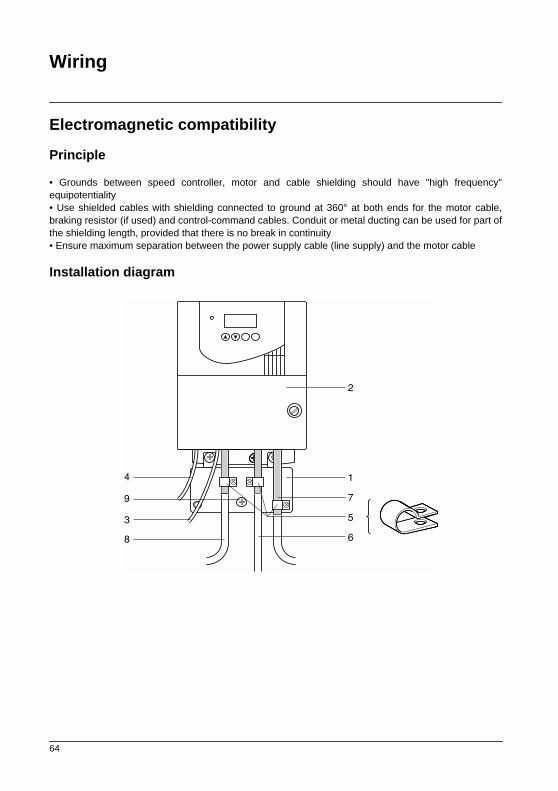
• Grounds between speed controller, motor and cable shielding should have "high frequency"equipotentiality• Use shielded cables with shielding connected to ground at 360° at both ends for the motor cable,braking resistor (if used) and control-command cables. Conduit or metal ducting can be used for part ofthe shielding length, provided that there is no break in continuity• Ensure maximum separation between the power supply cable (line supply) and the motor cable
Installation diagram
1
7
5
6
4
3
2
8
9
65
Wiring
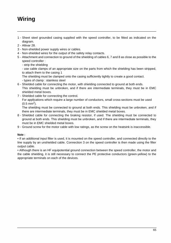
1 - Sheet steel grounded casing supplied with the speed controller, to be fitted as indicated on thediagram.
2 - Altivar 28. 3 - Non-shielded power supply wires or cables. 4 - Non-shielded wires for the output of the safety relay contacts. 5 - Attachment and connection to ground of the shielding of cables 6, 7 and 8 as close as possible to the
speed controller :- strip the shielding- use cable clamps of an appropriate size on the parts from which the shielding has been stripped,to attach them to the casing 1The shielding must be clamped onto the casing sufficiently tightly to create a good contact.- types of clamp : stainless steel
6 - Shielded cable for connecting the motor, with shielding connected to ground at both ends.This shielding must be unbroken, and if there are intermediate terminals, they must be in EMCshielded metal boxes.
7 - Shielded cable for connecting the control.For applications which require a large number of conductors, small cross-sections must be used (0.5 mm2).The shielding must be connected to ground at both ends. This shielding must be unbroken, and ifthere are intermediate terminals, they must be in EMC shielded metal boxes.
8 - Shielded cable for connecting the braking resistor, if used. The shielding must be connected toground at both ends. This shielding must be unbroken, and if there are intermediate terminals, theymust be in EMC shielded metal boxes.
9 - Ground screw for the motor cable with low ratings, as the screw on the heatsink is inaccessible.
Note : • If an additional input filter is used, it is mounted on the speed controller, and connected directly to theline supply by an unshielded cable. Connection 3 on the speed controller is then made using the filteroutput cable. • Although there is an HF equipotential ground connection between the speed controller, the motor andthe cable shielding, it is still necessary to connect the PE protective conductors (green-yellow) to theappropriate terminals on each of the devices.

66
Basic Functions
Fault relay, unlocking
The fault relay is energized when the speed controller is powered up and there is no fault. It has acommon point C/O contact.
The speed controller is unlocked after a fault by the following operations :
- Powering down the speed controller until the display and the red LED extinguish, then powering upagain- Automatically when the "automatic restart" function has been activated- Via a logic input when this input is assigned to the "fault reset" function
Speed controller thermal protection
Functions :Thermal protection by thermistor fitted on the heatsink or integrated in the power module.
Indirect protection of the speed controller against overloads by current limit. Typical tripping points :- motor current = 185 % of nominal speed controller current : 2 seconds- motor current = maximum speed controller transient current : 60 seconds
Speed controller ventilation
The fan is powered automatically when the speed controller is unlocked (operating direction +reference). It is powered down a few seconds after the speed controller is locked (motor speed < 0.5 Hzand injection braking completed).
Motor thermal protection
Function :Thermal protection by calculating I2t
Caution : The motor thermal state memory is reset to zero when the speed controller is switched off.

67
Configurable I/O Application Functions
Logic input application functions
Direction of operation : forward / reverseReverse operation can be disabled for applications with a single direction of motor rotation.
2-wire control :Run (forward or reverse) and stop are controlled by the same logic input, for which state 1 (run) or 0(stop) is taken into account.On power-up or a manual fault reset or after a stop command, the motor can only be powered once the"forward", "reverse" and "DC injection stop" commands have been reset. If the automatic restart functionis configured (parameter Atr in the drC menu), these commands are taken into account without a resetbeing necessary.
3-wire control :Run (forward or reverse) and stop are controlled by 2 different logic inputs.LI1 is always assigned to the stop function. Stop occurs on opening (state 0).The pulse on the run input is memorized until the stop input is opened.On power-up or a manual fault reset or after a stop command, the motor can only be powered once the"forward", "reverse" and "DC injection stop" commands have been reset.
Ramp switching : 1st ramp : ACC, dEC ; 2nd ramp : AC2, dE2This can be activated in 2 ways :- By activating a logic input LIx or by detection of an adjustable frequency threshold Frt.
Step by step operation (JOG): Low speed operation pulse
If the JOG contact is closed and an operating direction is activated or deactivated, the ramps are 0.1 sregardless of the ACC, dEC, AC2 and dE2 settings.
The minimum time between 2 JOG operations is 0.5 seconds.Parameter which can be accessed in the adjust menu :- JOG speed
68
Configurable I/O Application Functions
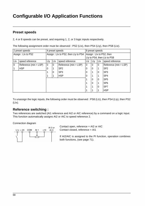
Preset speeds 2, 4 or 8 speeds can be preset, and requiring 1, 2, or 3 logic inputs respectively.
The following assignment order must be observed : PS2 (LIx), then PS4 (LIy), then PS8 (LIz).
To unassign the logic inputs, the following order must be observed : PS8 (LIz), then PS4 (LIy), then PS2(LIx).
Reference switching : Two references are switched (AI1 reference and AI2 or AIC reference) by a command on a logic input.This function automatically assigns AI2 or AIC to speed reference 2.
Connection diagramContact open, reference = AI2 or AICContact closed, reference = AI1
If AI2/AIC is assigned to the PI function, operation combinesboth functions, (see page 71).
2 preset speeds 4 preset speeds 8 preset speedsAssign : LIx to PS2 Assign : LIx to PS2, then LIy to PS4 Assign : LIx to PS2, then
LIy to PS4, then LIz to PS8LIx speed reference LIy LIx speed reference LIz LIy LIx speed reference0 Reference (min = LSP) 0 0 Reference (min = LSP) 0 0 0 Reference (min = LSP)1 HSP 0 1 SP2 0 0 1 SP2
1 0 SP3 0 1 0 SP31 1 HSP 0 1 1 SP4
1 0 0 SP51 0 1 SP61 1 0 SP71 1 1 HSP
COM +10AI 1LI x + 24
AI 2 or
AI C

69
Configurable I/O Application Functions
Freewheel stop
Stops the motor by the resistive torque only. The motor power supply is cut.Freewheel stop occurs when the logic input assigned to this function opens (state 0).
DC injection stop
This can be activated in 2 ways :- by activation of a logic input assigned to this function (state 1)- automatically if the frequency is below 0.5 Hz
Fast stop : Braked stop with the current deceleration ramp time divided by 4 within the limits of the brakingpossibilities.Fast stop occurs when the logic input assigned to this function opens (state 0). On this type of stop, noDC injection at the end of the ramp.
Fault reset :
Clears the memorized fault and resets the speed controller if the cause of the fault has disappeared,except for OCF (overcurrent), SCF (motor short-circuit), EEF and InF (internal faults) faults, whichrequire the controller to be powered down.The fault is cleared when the logic input assigned to this function changes from 0 to 1.
Forced local mode when using the serial link :
Changes from line control mode (serial link) to local mode (control via the terminal block).

70
Configurable I/O Application Functions
Analog input application functions
Input AI1 is always the reference.
Assignment of AI2/AIC (AI2 = 0, +10 V or AIC = X-Y mA, X and Y can be configured from 0 to 20mA)Assign CCCCrrrrLLLL and CCCCrrrrHHHH (I/O assignment menu)Summing speed reference : The frequency reference from AI2/AIC can be summed with AI1.
PI regulator : Can be assigned to AI2/AIC. Allows a sensor to be connected and activates the PIregulator. The PI function is programmed via AIC in the I/O menu. The 2 parameters used to configure the PIfunction are: - AIC = PIA configuration of the PI reference at the terminal on AI1. The reference is input AI1 and thefeedback is AI2 or AIC. The PI regulator output becomes the frequency reference.Application: process control which can be controlled by the motor speed.- AIC = PII configuration of the internal reference rPI which can be adjusted via the keypad (SSSSEEEEtttt adjustmenu). The feedback is AI2 or AIC.
Parameters which can be accessed in the adjust menu SSSSEEEEtttt: - regulator proportional gain (rPG)- regulator integral gain (rIG)- PI feedback multiplication coefficient (FbS) : is used to adjust the max. value of the feedback so that it corresponds to the max. value of the PI regulator reference.- reversal of the direction of correction (PIC) : if PIC = no, the motor speed increases when the error ispositive, example: pressure control with a compressor.if PIC = YES, the motor speed decreases when the error is positive, example: temperature control via acooling fan.
x Fb5(0,1É100)
rPG
rPI
X1
X-1
rIG
YES
no
PIC
LSP
HSPorAI1
AI2
or
AIC 0.01 to 100 0.01 to 100 x 1/S
Ref.

71
Configurable I/O Application Functions
Recommendations:• In 2-wire control (TCC=2C), do not assign Atr to no (drC menu)• In 3-wire control (TCC=3C), the PI output (ref.) must be greater than 0.7 Hz. If it is less than 0.7 Hz, thisstate is interpreted as a stop (machine safety regulations). In order to restart, the PI ref. must be greaterthan 0.7 Hz. LSP must be set to a value greater than 0.7 Hz. To stop the motor, set LI1 (STOP) = 0
Notes:The PI function is incompatible in terminal mode (LCC = Yes).
"Manual - Automatic" operation with PI
This function combines the PI regulator and reference switching by a logic input. The speed referenceis given by AI1 or by the PI function, depending on the state of the logic input.
x Fb5(0,1É100)
rPG
rPI
X1
X-1
rIG
YES
no
PIC
LSP
HSP
AI2orAIC
orAI1
LIX=rFC and LIX=0
Ref. (0-AImax)Man
Auto

72
Configurable I/O Application Functions
R2 relay application functions
Frequency threshold reached (FtA) : The relay contact is closed if the motor frequency is greater than orequal to the frequency threshold set by Ftd in the adjust menu.
Speed reference reached (SrA) : The relay contact is closed if the motor frequency is greater than or equalto the speed reference value.
Current threshold reached (CtA) : The relay contact is closed if the motor current is greater than or equalto the current threshold set by Ctd in the adjust menu.
Thermal state reached (tSA) : The relay contact is closed if the motor thermal state is greater than or equalto the thermal state threshold set by ttd in the adjust menu.
Analog output AO application functions
Analog output AO is a current output, which can be configured for 0 - 20 mA or 4 - 20 mA.
Motor current (code OCr) : supplies the image of the motor rms current.20 mA corresponds to twice the nominal drive current.
Motor frequency (code rFr) : supplies the motor frequency calculated by the speed controller.20 mA corresponds to the maximum frequency (parameter tFr).
Motor torque (code OLO) : supplies the image of the motor torque as an absolute value.20 mA corresponds to twice the nominal motor torque (typical value).
Power (code OPr) : supplies the image of the power supplied to the motor by the speed controller.20 mA corresponds to twice the nominal speed controller power (typical value).
73
Configurable I/O Application Functions
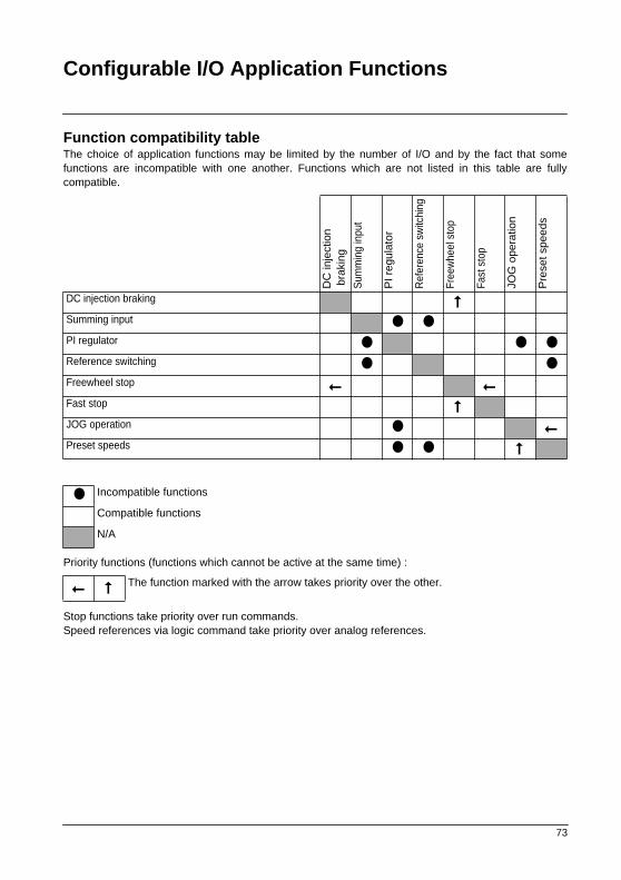
Function compatibility tableThe choice of application functions may be limited by the number of I/O and by the fact that somefunctions are incompatible with one another. Functions which are not listed in this table are fullycompatible.
Priority functions (functions which cannot be active at the same time) :
Stop functions take priority over run commands.Speed references via logic command take priority over analog references.
DC
inje
ctio
n b
raki
ng
Sum
min
g in
put
PI r
egul
ator
Ref
eren
ce s
witc
hing
Free
whe
el s
top
Fast
sto
p
JOG
ope
ratio
n
Pre
set s
peed
s
DC injection braking
Summing input PI regulator Reference switching Freewheel stop
Fast stop
JOG operation Preset speeds
Incompatible functions
Compatible functions
N/A
The function marked with the arrow takes priority over the other.
74
Setup - Preliminary Recommendations
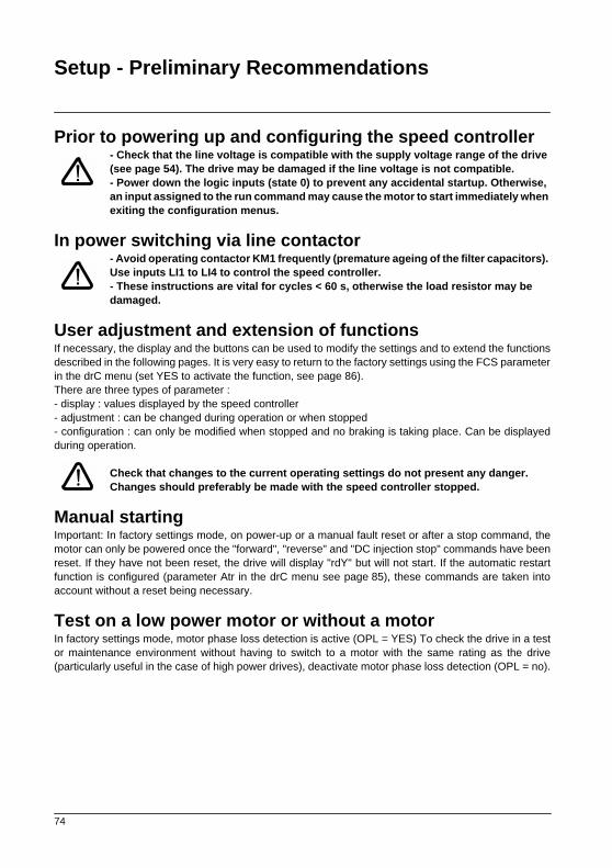
Prior to powering up and configuring the speed controller- Check that the line voltage is compatible with the supply voltage range of the drive (see page 54). The drive may be damaged if the line voltage is not compatible.- Power down the logic inputs (state 0) to prevent any accidental startup. Otherwise, an input assigned to the run command may cause the motor to start immediately when exiting the configuration menus.
In power switching via line contactor - Avoid operating contactor KM1 frequently (premature ageing of the filter capacitors). Use inputs LI1 to LI4 to control the speed controller.- These instructions are vital for cycles < 60 s, otherwise the load resistor may be damaged.
User adjustment and extension of functionsIf necessary, the display and the buttons can be used to modify the settings and to extend the functionsdescribed in the following pages. It is very easy to return to the factory settings using the FCS parameterin the drC menu (set YES to activate the function, see page 86).There are three types of parameter :- display : values displayed by the speed controller- adjustment : can be changed during operation or when stopped- configuration : can only be modified when stopped and no braking is taking place. Can be displayedduring operation.
Check that changes to the current operating settings do not present any danger. Changes should preferably be made with the speed controller stopped.
Manual startingImportant: In factory settings mode, on power-up or a manual fault reset or after a stop command, themotor can only be powered once the "forward", "reverse" and "DC injection stop" commands have beenreset. If they have not been reset, the drive will display "rdY" but will not start. If the automatic restartfunction is configured (parameter Atr in the drC menu see page 85), these commands are taken intoaccount without a reset being necessary.
Test on a low power motor or without a motorIn factory settings mode, motor phase loss detection is active (OPL = YES) To check the drive in a testor maintenance environment without having to switch to a motor with the same rating as the drive(particularly useful in the case of high power drives), deactivate motor phase loss detection (OPL = no).
75
Programming
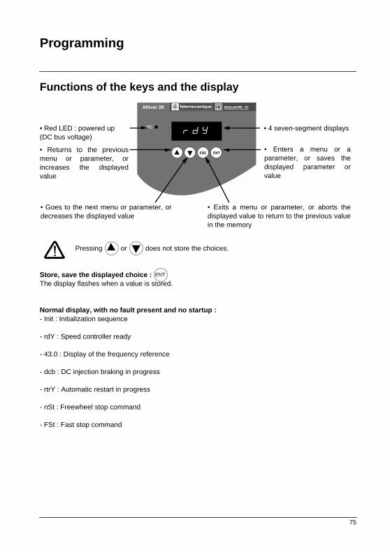
Functions of the keys and the display
Pressing or does not store the choices.
Store, save the displayed choice : The display flashes when a value is stored.
Normal display, with no fault present and no startup :- Init : Initialization sequence
- rdY : Speed controller ready
- 43.0 : Display of the frequency reference
- dcb : DC injection braking in progress
- rtrY : Automatic restart in progress
- nSt : Freewheel stop command
- FSt : Fast stop command
Altivar 28
zrdY
ESC ENT
TeDR
• Red LED : powered up(DC bus voltage)
• 4 seven-segment displays
• Enters a menu or aparameter, or saves thedisplayed parameter orvalue
• Returns to the previousmenu or parameter, orincreases the displayedvalue
• Exits a menu or parameter, or aborts thedisplayed value to return to the previous valuein the memory
• Goes to the next menu or parameter, ordecreases the displayed value
ENT
76
Programming
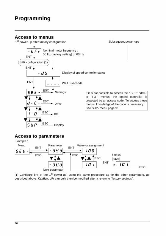
Access to menus
Access to parametersExample :
(1) Configure bFr at the 1st power-up, using the same procedure as for the other parameters, asdescribed above. Caution, bFr can only then be modified after a return to "factory settings".
Subsequent power ups1st power-up after factory configuration
Display of speed controller status
Drive
I/O
Nominal motor frequency : 50 Hz (factory setting) or 60 Hz
----bbbbFFFFrrrr
rrrrddddYYYY
----------------
SSSSEEEEtttt----
ddddrrrrCCCC----
SSSSUUUUPPPP----
ENT
ENT
bFR configuration (1)
ENT
ESC
ESC
ESC
ESC
IIII----0000----
Settings
Display
Wait 3 seconds
If it is not possible to access the " SEt-", "drC-"or "I-O-" menus, the speed controller isprotected by an access code. To access thesemenus, knowledge of the code is necessary. See SUP- menu page 91.
SSSSEEEEtttt----ESC
----YYYYYYYYYYYY
Menu
----UUUUUUUUUUUU
111100000000
111100001111 111100001111
ESC
ENT ENT
ENT
ESC
Parameter Value or assignment
Next parameter
1 flash(save)
ESC

77
Local control option
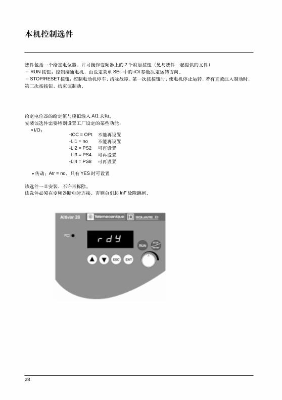
This option consists of a reference potentiometer and provides access to 2 additional buttons on thespeed controller (see documentation provided with the option) :- RUN button : controls the switching on of the motor. The direction of operation is determined by
parameter rOt in the settings menu SEt-.- STOP/RESET button : controls the stopping of the motor and the clearing (resetting) of any
faults The first press on the button stops the motor, and if DC injection standstill braking is configured, a second press stops this braking.
The reference given by the reference potentiometer is summed with analog input AI1.Installing this option requires special factory setting of certain functions :
• I/O : -tCC = OPt not reassignable-LI1 = no not reassignable-LI2 = PS2 reassignable-LI3 = PS4 reassignable-LI4 = PS8 reassignable
• Drive : Atr = no, only reassignable at YES
This option cannot be removed once it has been fitted.The option must be connected with the speed controller powered down, otherwise it will trip on an InFfault.
Altivar 28
zrdY
ESC ENT
TeDR
RUN
STOP
RESET

78
Remote Display Module Option
This module is a local control unit which can be mounted on the door of the wall mounted or floor-standing enclosure. It has a cable with connectors, which is connected to the speed controller serial link(see the manual supplied with the display module). It has the same display and the same programmingbuttons as the Altivar 28 with the addition of a switch to lock access to the menus and three buttons forcontrolling the speed controller :• FWD/RV : reversal of the direction of rotation• RUN : motor run command• STOP/RESET : motor stop command or fault reset
The first press on the button stops the motor, and if DC injection standstill braking is configured, a second press stops this braking.
View of the front panel : View of the rear panel :
Set bdr to 19.2 (I/O menu see page 97)
ESC
ENT
RUNFWD
REV
STOP
RESET
4-character display
Connector
Access switch :• position : settings and configuration not accessible• position : settings accessible• position : settings and configuration accessible

79
Configuration
I/O assignment menuThe parameters can only be modified when the speed controller is stopped and locked.The functions are defined in the section "Configurable I/O Application Functions".
Code Assignment Factory setting
----ttttCCCCCCCC Configuration of terminal block control : 2-wire or 3-wire control.2C = 2-wire, 3C = -wire, OPt = presence of the local control option, operation is then identical to 3-wire control.
2-wire control : The open or closed state of the input controls running or stopping.Wiring example :LI1 : forwardLIX : reverse
3-wire control (pulse control) : one pulse is all that is needed to control start-up. Wiring example :LI1 : stopLI2 : forwardLIx : reverse
Changing the assignment of tCC returns the logic inputs to factory setting :
• tCC = 2C : LI1 : "Forward", cannot be reassigned LI2 : rrS ("Reverse") LI3 : PS2 LI4 : PS4
• tCC = 3C : LI1 : Stop, cannot be reassigned LI2 : For ("Forward"), cannot be reassigned LI3 : rrS ("Reverse") LI4 : JOG
• tCC = OPt : LI1 : no, cannot be reassigned LI2 : PS2 LI3 : PS4 LI4 : PS8
2C
----LLLLCCCCCCCC Parameter only accessible with the remote display module option : no - YESEnables control of the speed controller using the STOP/RESET, RUN and FWD/REV buttons on the display module. The speed reference is then given by parameter LFr in the SEt- menu. Only the freewheel, fast stop and DC injection stop commands remain active on the terminal block. If the speed controller / display module link is broken, the speed controller locks on an SLF fault.
no
IIII----0000----
24 V LI1 LIx
ATV-28
24 V LI1 LI2 LIx
ATV-28
80
Configuration
I/O assignment menu (continued)
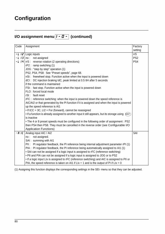
(1) Assigning this function displays the corresponding settings in the SEt- menu so that they can be adjusted.
Code Assignment Factory setting
----LLLLIIII2222
----LLLLIIII3333
----LLLLIIII4444
Logic inputsno : not assignedrrS : reverse rotation (2 operating directions)rP2 : ramp switching (1)JOG : "step by step" operation (1)PS2, PS4, PS8: See “Preset speeds”, page 68.nSt : freewheel stop. Function active when the input is powered downdCI : DC injection braking IdC, peak limited at 0.5 ItH after 5 seconds if the command is maintainedFSt : fast stop. Function active when the input is powered downFLO : forced local moderSt : fault resetrFC : reference switching: when the input is powered down the speed reference isAIC/AI2 or that generated by the PI function if it is assigned and when the input is powered up the speed reference is AI1 • If tCC = 3C, LI2 = For (forward), cannot be reassigned• If a function is already assigned to another input it still appears, but its storage using is inactive• The 4 or 8 preset speeds must be configured in the following order of assignment : PS2 then PS4 then PS8. They must be cancelled in the reverse order (see Configurable I/O Application Functions)
rrSPS2PS4
----AAAAIIIICCCC Analog input AIC / AI2no : not assigned.SAI : summing with AI1PII : PI regulator feedback, the PI reference being internal adjustment parameter rPI (1)PIA : PI regulator feedback, the PI reference being automatically assigned to AI1 (1)• SAI can not be assigned if a logic input is assigned to rFC (reference switching)• PII and PIA can not be assigned if a logic input is assigned to JOG or to PS2• If a logic input LIx is assigned to rFC (reference switching) and AIC is assigned to PII or PIA, the speed reference is taken on AI1 if LIx = 1 and is the output of PI if LIx = 0
SAI
IIII----0000----
ENT

81
Configuration
I/O assignment menu (continued)
Code Assignment Factory setting
----CCCCrrrrLLLL
----CCCCrrrrHHHH
Minimum value on input AIC, adjustable from 0 to 20 mA.Maximum value on input AIC, adjustable from 0 to 20 mA.These two parameters are used to configure the input for 0-20 mA, 4-20 mA, 20-4 mA, etc.
If the input used is AI2, these parameters remain proportionally active :4 mA v 2 V20 mA v 10 VFor a 0 - 10 V input, configure CrL at 0 and CrH at 20.These parameters should be adjusted when the PI function is activated.
4 mA20 mA
----AAAAOOOO Analog outputno : not assignedOCr : motor current. 20 mA corresponds to twice the nominal drive currentrFr : motor frequency. 20 mA corresponds to the maximum frequency tFrOLO : motor torque. 20 mA corresponds to twice the nominal motor torqueOPr : power supplied by the speed controller. 20 mA corresponds to twice the nominal drive power
rFr
----AAAAOOOOtttt Analog output0 : 0-20 mA configuration4 : 4-20 mA configuration
0
IIII----0000----
AI C(mA)0
LSP
HSP
CrL CrH 20
Frequency

82
Configuration
I/O assignment menu (continued)
(1) Assigning this function displays the corresponding settings in the SEt- menu so that they can be adjusted.
Code Assignment Factory setting
----rrrr2222 Relay R2no : not assignedFtA : frequency threshold reached. The contact is closed if the motor frequency is
greater than or equal to the threshold set by Ftd (1)CtA : current threshold reached. The contact is closed if the motor current is greater than
or equal to the threshold set by Ctd (1)SrA : speed reference reached. The contact is closed if the motor frequency is greater than or equal to the speed referencetSA : thermal threshold reached. The contact is closed if the motor thermal state is greater than or equal to the threshold set by ttd (1)
SrA
----AAAAdddddddd Address of the speed controller when it is controlled via the serial link.Adjustable from 1 to 31.
1
----bbbbddddrrrr Serial link transmission speed :9.6 = 9600 bits / s or 19.2 = 19200 bits / s19200 bits/ s is the transmission speed for operating the remote display module.Modification of this parameter is only taken into account after the speed controller has been powered down then powered up.
19.2
IIII----0000----
83
Configuration
Drive menu
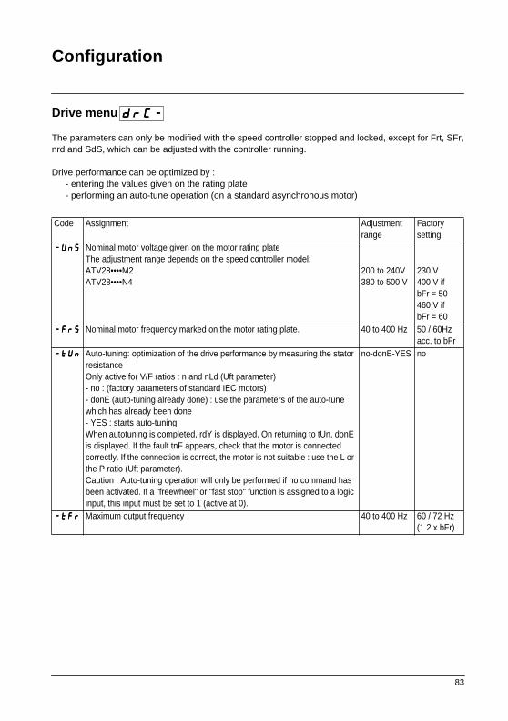
The parameters can only be modified with the speed controller stopped and locked, except for Frt, SFr,nrd and SdS, which can be adjusted with the controller running.
Drive performance can be optimized by :- entering the values given on the rating plate- performing an auto-tune operation (on a standard asynchronous motor)
Code Assignment Adjustmentrange
Factory setting
----UUUUnnnnSSSS Nominal motor voltage given on the motor rating plateThe adjustment range depends on the speed controller model: ATV28••••M2ATV28••••N4
200 to 240V380 to 500 V
230 V400 V ifbFr = 50460 V ifbFr = 60
----FFFFrrrrSSSS Nominal motor frequency marked on the motor rating plate. 40 to 400 Hz 50 / 60Hzacc. to bFr
----ttttUUUUnnnn Auto-tuning: optimization of the drive performance by measuring the stator resistanceOnly active for V/F ratios : n and nLd (Uft parameter)- no : (factory parameters of standard IEC motors)- donE (auto-tuning already done) : use the parameters of the auto-tune which has already been done- YES : starts auto-tuningWhen autotuning is completed, rdY is displayed. On returning to tUn, donE is displayed. If the fault tnF appears, check that the motor is connected correctly. If the connection is correct, the motor is not suitable : use the L or the P ratio (Uft parameter).Caution : Auto-tuning operation will only be performed if no command has been activated. If a "freewheel" or "fast stop" function is assigned to a logic input, this input must be set to 1 (active at 0).
no-donE-YES no
----ttttFFFFrrrr Maximum output frequency 40 to 400 Hz 60 / 72 Hz(1.2 x bFr)
ddddrrrrCCCC----

84
Configuration
Drive menu (continued)
Code Assignment Adjustmentrange
Factory setting
----UUUUFFFFtttt Selection of the type of voltage / frequency ratio- L : constant torque for motors connected in parallel or special motors- P : variable torque: pump and fan applications- n : sensorless flux vector control for constant torque applications- nLd : energy saving, for variable torque applications or constant torque applications not requiring high dynamics
L - P - n - nLd n
----bbbbrrrrAAAA Activating this function automatically adapts the deceleration ramp, if this has been set at too low a value for the inertia of the load.no : function inactive. YES : function active.The adaptation of the deceleration ramp depends on the dEC settings and the gain FLG (see SET adjust menu page 89).The function is incompatible with: • positioning on a ramp• the use of a braking resistor
no - YES YES
----FFFFrrrrtttt Ramp switching frequencyWhen the output frequency becomes greater than Frt, the ramp times taken into account are AC2 and dE2. If Frt = 0, the function is inactive.This parameter does not appear if a logic input is assigned to the ramp switching function rP2.
0 to HSP 0 Hz
----SSSSFFFFrrrr Switching frequencyThe switching frequency can be adjusted to reduce the noise generated by the motor.Above 4 kHz, the speed controller output current must be derated :• up to 12 kHz : derated by 1.25% per kHz or 10% at 12 kHz• above 12 kHz : derated by 10% + 3.3 % per kHz or 19.9% at 15 kHz
2 to 15 kHz 4.0
----nnnnrrrrdddd This function randomly modulates the switching frequency to reduce the motor noise. no : function inactive. YES : function active.
no - YES YES
Parameter can be adjusted during operation.
ddddrrrrCCCC----

85
Configuration
Drive menu (continued)Code Assignment Adjustment
rangeFactory setting
----AAAAttttrrrr Automatic restart, after locking on a fault, if the fault has disappeared and the other operating conditions permit the restart. The restart is performed by a series of automatic attempts separated by increasingly longer waiting periods : 1 s, 5 s, 10 s, then 1 min for the following attempts. If the restart has not taken place after 6 min, the procedure is aborted and the speed controller remains locked until it is powered down then powered up. The following faults permit this function : OHF, OLF, USF, ObF, OSF, PHF, OPF, SLF. The speed controller fault relay remains activated if this function is active. The speed reference and the operating direction must be maintained.This function can only be used in 2-wire control (tCC = 2C).
Check that any accidental start does not present any danger to personnel or equipment.- no : Function inactive- YES : Function active- USF : Function only active for the USF fault
no - YES - USF
no
----OOOOPPPPLLLL Enables the motor phase failure fault.- no : function inactive- YES : function active (motor phase loss detection)- OAC: activation of the function manages the presence of a downstream contactor
no - YES - OAC
YES
----IIIIPPPPLLLL Enables the line supply phase failure fault.no : function inactive. YES : function active.This parameter does not exist on the ATV28HU09M2, U18M2, U29M2 and U41M2 for a single phase line supply.The fault is only detected if the motor is on-load (around 0.7 times the nominal power). At low load, single phase operation does not cause damage.
no - YES YES
----SSSSttttPPPP Controlled stop on loss of line supply :Controls the stopping of the motor when there is a loss of line supply, following a ramp which can be adjusted via FLG (see SET adjust menu page 89) according to the kinetic energy restored.no : function inactive. YES : function active.
no - YES no
ddddrrrrCCCC----

86
Configuration
Drive menu (continued)Code Assignment Adjustment
rangeFactory setting
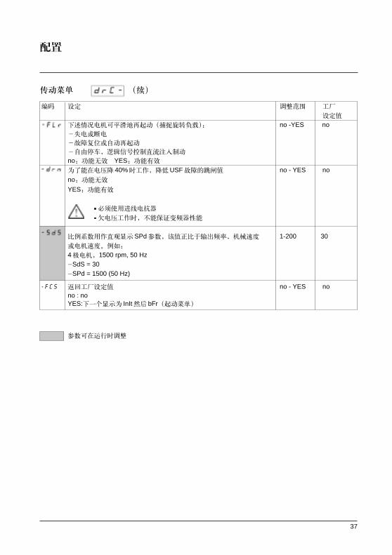
----FFFFLLLLrrrr Enables a smooth restart (catch a spinning load) after the following events :- loss of line supply or power off- fault reset or automatic restart- freewheel stop or DC injection stop with logic inputno : function inactive. YES : function active.
no - YES no
----ddddrrrrnnnn Lowers the tripping threshold of the USF fault in order to operate on a line supply with 40% voltage drops.no : function inactive.YES : function active :
• A line choke must be used• The performance of the speed controller can no longer be guaranteed when operating at undervoltage
no - YES no
----SSSSddddSSSS Scale factor for the display parameter SPd (-SUP menu), used to scale a value in proportion to the output frequency, the machine speed or the motor speed. For example : 4-pole motor, 1500 rpm at 50 Hz :-SdS = 30-SPd =1500 at 50 Hz
1 to 200 30
----FFFFCCCCSSSS Return to factory settings (except LCC setting, see I/O menu page 79)no : noYES : the next display will be InIt then bFr (start of the menus)
no - YES no
Parameter can be adjusted during operation.
ddddrrrrCCCC----
87
Settings
Adjust menu
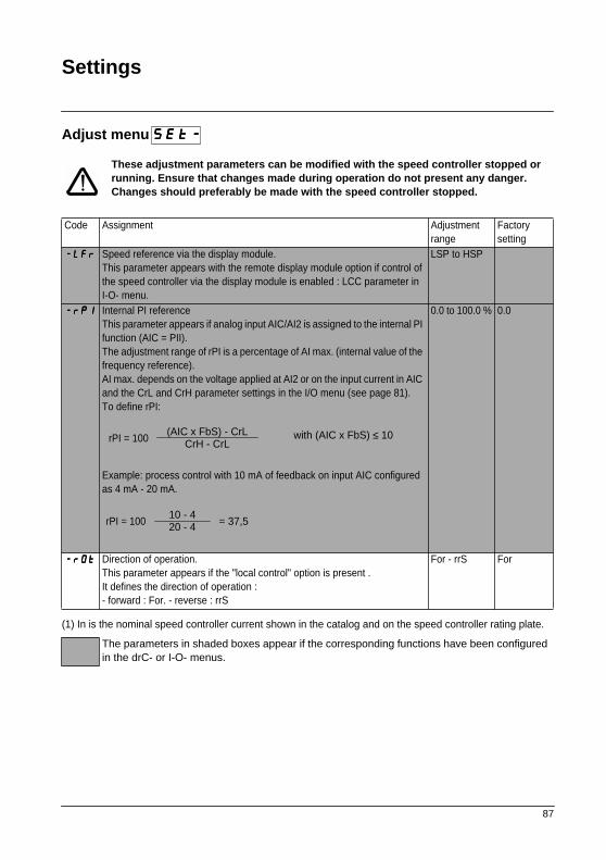
These adjustment parameters can be modified with the speed controller stopped or running. Ensure that changes made during operation do not present any danger. Changes should preferably be made with the speed controller stopped.
(1) In is the nominal speed controller current shown in the catalog and on the speed controller rating plate.
Code Assignment Adjustmentrange
Factory setting
----LLLLFFFFrrrr Speed reference via the display module.This parameter appears with the remote display module option if control of the speed controller via the display module is enabled : LCC parameter in I-O- menu.
LSP to HSP
----rrrrPPPPIIII Internal PI referenceThis parameter appears if analog input AIC/AI2 is assigned to the internal PI function (AIC = PII).The adjustment range of rPI is a percentage of AI max. (internal value of the frequency reference).AI max. depends on the voltage applied at AI2 or on the input current in AIC and the CrL and CrH parameter settings in the I/O menu (see page 81).To define rPI:
Example: process control with 10 mA of feedback on input AIC configured as 4 mA - 20 mA.
0.0 to 100.0 % 0.0
----rrrrOOOOtttt Direction of operation.This parameter appears if the "local control" option is present .It defines the direction of operation :- forward : For. - reverse : rrS
For - rrS For
The parameters in shaded boxes appear if the corresponding functions have been configured in the drC- or I-O- menus.
SSSSEEEEtttt----
rPI = 100(AIC x FbS) - CrL
CrH - CrL with (AIC x FbS) ≤ 10
rPI = 10010 - 420 - 4 = 37,5

88
Settings
Adjust menu (continued)
(1) In is the nominal speed controller current shown in the catalog and on the speed controller ratingplate.
Code Assignment Adjustmentrange
Factory setting
----AAAACCCCCCCC
----ddddEEEECCCC
Acceleration and deceleration ramp times. Defined to range from 0 to nominal frequency bFr.Ensure that the value of dEC is not too low in relation to the load to be stopped.
0,0 to 3600 s0.0 to 3600 s
3 s3 s
----AAAACCCC2222
----ddddEEEE2222
2nd acceleration ramp time2nd deceleration ramp timeThese parameters are accessible if the ramp switching threshold (Frt parameter in the drC- menu) is other than 0 Hz or if a logic input is assigned to ramp switching.
0,0 to 3600 s0.0 to 3600 s
5 s5 s
----LLLLSSSSPPPP Low speed 0 to HSP 0 Hz ----HHHHSSSSPPPP High speed : ensure that this setting is appropriate for the motor and the
application.LSP to tFr bFr
----IIIIttttHHHH Current used for the motor thermal protection. Set ItH to the nominal current marked on the motor rating plate.To disable thermal protection, increase the value to the maximum (ntH displayed).
0,20 to 1,15In (1)
In (1)
----UUUUFFFFrrrr Optimizes the torque at very low speed.Ensure that the value of UFr is not too high which will cause the motor to saturate.
0 to 100 % 20
----SSSSLLLLPPPP Adjusts the slip compensation around the value set by the nominal motor speed. This parameter only appears if parameter UFt = n in the drC- menu.
0.0 to 5.0 Hz According to controller output
The parameters in shaded boxes appear if the corresponding functions have been configured in the drC- or I-O- menus.
SSSSEEEEtttt----

89
Settings
Adjust menu (continued)
(1) In is the nominal speed controller current shown in the catalog and on the speed controller ratingplate.
Code Assignment Adjustmentrange
Factory setting
----FFFFLLLLGGGG Frequency loop gain, acts primarily when brA=YES (see page 97) and during deceleration. Practical advice:- machines with high inertia: gradually reduce the value in the event of overvoltage faults on deceleration (OBF)- machines with fast cycles or low inertia: gradually increase the gain FLGto optimize the following of the deceleration ramp (dEC) and limit thenumber of overvoltage faults on deceleration (OBF)Too high a gain may result in operating instability.
0 to 100 % 33
----IIIIddddCCCC Level of DC injection braking currentAfter 5 seconds the injection current is peak limited at 0.5 Ith if it is set at a higher value.
0.1 ItH to In (1)
0.7 In (1)
----ttttddddCCCC DC injection standstill braking timeIf the time is increased to 25.5 s, "Cont" is displayed. The DC injection is then continuous at standstill.
0 to 25,4 sCont.
0.5 s
----JJJJPPPPFFFF Skip frequency prevents prolonged operation at a frequency range of 2 Hz around JPF. This function prevents a critical speed which leads to resonance.Setting the function to 0 renders it inactive.
0 to HSP 0 Hz
----JJJJOOOOGGGG Jog operating frequency 0 to 10 Hz 10 Hz ----rrrrPPPPGGGG PI regulator proportional gain, contributes to dynamic performance during
rapid changes in the PI feedback.0,01 to 100 1
----rrrrIIIIGGGG PI regulator integral gain, contributes to the static precision during slow changes in the PI feedback.
0.01 to 100 / s 1 / s
----FFFFbbbbSSSS PI feedback multiplication coefficient 0.1 to 100 1----PPPPIIIICCCC Reversal of the direction of correction of the PI regulator :
no : normal. YES : reverse.no - YES no
The parameters in shaded boxes appear if the corresponding functions have been configured in the drC- or I-O- menus.
SSSSEEEEtttt----
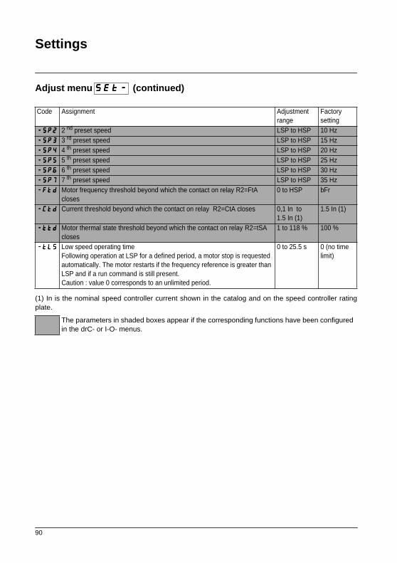
90
Settings
Adjust menu (continued)
(1) In is the nominal speed controller current shown in the catalog and on the speed controller ratingplate.
Code Assignment Adjustmentrange
Factory setting
----SSSSPPPP2222 2 nd preset speed LSP to HSP 10 Hz ----SSSSPPPP3333 3 rd preset speed LSP to HSP 15 Hz ----SSSSPPPP4444 4 th preset speed LSP to HSP 20 Hz ----SSSSPPPP5555 5 th preset speed LSP to HSP 25 Hz ----SSSSPPPP6666 6 th preset speed LSP to HSP 30 Hz ----SSSSPPPP7777 7 th preset speed LSP to HSP 35 Hz ----FFFFttttdddd Motor frequency threshold beyond which the contact on relay R2=FtA
closes0 to HSP bFr
----CCCCttttdddd Current threshold beyond which the contact on relay R2=CtA closes 0,1 In to 1.5 In (1)
1.5 In (1)
----ttttttttdddd Motor thermal state threshold beyond which the contact on relay R2=tSA closes
1 to 118 % 100 %
----ttttLLLLSSSS Low speed operating timeFollowing operation at LSP for a defined period, a motor stop is requested automatically. The motor restarts if the frequency reference is greater than LSP and if a run command is still present.Caution : value 0 corresponds to an unlimited period.
0 to 25.5 s 0 (no time limit)
The parameters in shaded boxes appear if the corresponding functions have been configured in the drC- or I-O- menus.
SSSSEEEEtttt----
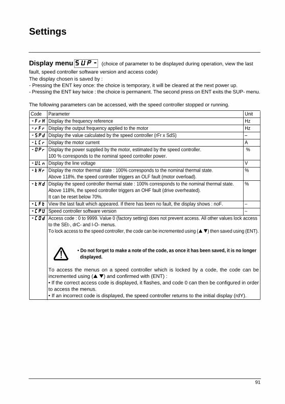
91
Settings
Display menu (choice of parameter to be displayed during operation, view the last
fault, speed controller software version and access code)The display chosen is saved by :- Pressing the ENT key once: the choice is temporary, it will be cleared at the next power up.- Pressing the ENT key twice : the choice is permanent. The second press on ENT exits the SUP- menu.
The following parameters can be accessed, with the speed controller stopped or running.
Code Parameter Unit----FFFFrrrrHHHH Display the frequency reference Hz----rrrrFFFFrrrr Display the output frequency applied to the motor Hz----SSSSPPPPdddd Display the value calculated by the speed controller (rFr x SdS) –----LLLLCCCCrrrr Display the motor current A----OOOOPPPPrrrr Display the power supplied by the motor, estimated by the speed controller.
100 % corresponds to the nominal speed controller power. %
----UUUULLLLnnnn Display the line voltage V----ttttHHHHrrrr Display the motor thermal state : 100% corresponds to the nominal thermal state.
Above 118%, the speed controller triggers an OLF fault (motor overload).%
----ttttHHHHdddd Display the speed controller thermal state : 100% corresponds to the nominal thermal state. Above 118%, the speed controller triggers an OHF fault (drive overheated). It can be reset below 70%.
%
----LLLLFFFFtttt View the last fault which appeared. If there has been no fault, the display shows : noF. –----CCCCPPPPUUUU Speed controller software version –----CCCCOOOOdddd Access code : 0 to 9999. Value 0 (factory setting) does not prevent access. All other values lock access
to the SEt-, drC- and I-O- menus.To lock access to the speed controller, the code can be incremented using ( ) then saved using (ENT).
• Do not forget to make a note of the code, as once it has been saved, it is no longer displayed.
To access the menus on a speed controller which is locked by a code, the code can beincremented using ( ) and confirmed with (ENT) :• If the correct access code is displayed, it flashes, and code 0 can then be configured in orderto access the menus.• If an incorrect code is displayed, the speed controller returns to the initial display (rdY).
SSSSUUUUPPPP----
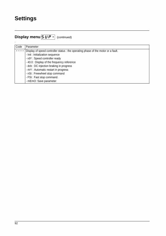
92
Settings
Display menu (continued).
Code Parameter---------------- Display of speed controller status : the operating phase of the motor or a fault.
- Init : Initialization sequence- rdY : Speed controller ready- 43.0 : Display of the frequency reference- dcb : DC injection braking in progress- rtrY : Automatic restart in progress- nSt : Freewheel stop command- FSt : Fast stop command.- mEmO: Save parameter
SSSSUUUUPPPP----

93
Maintenance
Servicing The Altivar 28 does not require any preventative maintenance. It is nevertheless advisable to carry outthe following operations regularly :- Check the condition and tightness of connections- Check that the temperature around the unit remains at an acceptable level and that the
ventilation is effective (average service life of fans : 3 to 5 years depending on operatingconditions)
- Remove any dust from the speed controller
Assistance with maintenance
If there is a problem when starting up or during operation, firstly check that the recommendations relatingto the environment, mounting and connections have been followed.
The first fault detected is memorized and displayed on the screen : the speed controller locks and faultrelay R1 is tripped.
Clearing faults
Switch off the speed controller power supply in the event of a fault which cannot be reset.Wait for the LED and the display to go off completely.Find the cause of the fault in order to correct it.Restore the power supply : this will clear the fault if it has disappeared.
In some cases there may be an automatic restart after the fault has disappeared if this function has beenprogrammed (see Atr menu drC page 85).
Display menu
This is used to prevent and find the causes of faults by displaying the speed controller status and itscurrent values.
Spares and repairs
Consult Schneider Electric product support.

94
Faults - Causes - Remedies
Speed controller does not start, no fault displayed
• The assignment of the "Fast stop" or "Freewheel stop" functions will prevent the controller from startingif the corresponding logic inputs are not powered up. The ATV-28 then displays "nSt" in freewheel stopmode and "FSt" in fast stop mode. This is normal since these functions are active at zero so that thecontroller will be stopped safely if there is a wire break.• On power-up or a manual fault reset or after a stop command, the motor can only be powered once the"forward", "reverse" and "DC injection stop" commands have been reset. If they have not been reset, thespeed controller will display "rdY" but will not start. If the automatic restart function is configured (parameterAtr in the drC menu), these commands are taken into account without a reset being necessary.
Faults which cannot be reset automatically
The cause of the fault must be corrected before resetting by powering down and then powering up.
Fault Probable cause Remedy
----OOOOCCCCFFFF
overcurrent- ramp too short- inertia or load too high- mechanical blocking- motor phase short-circuit
- Check the settings- Check the motor/speed controller/load sizing- Check the state of the mechanism- Check the cables connecting the drive to the motor
----SSSSCCCCFFFF
motor short-circuit - short-circuit or earthing at the speed controller output- significant earth leakage current at the drive output if several motors are connected in parallel
- Check the cables connecting the speed controller to the motor, and the insulation of the motor- Adjust the switching frequency- Add motor chokes
----IIIInnnnFFFF
internal fault- internal fault - Check the environment (electromagnetic compatibility)
- Check that the "local control" option has not been connected or disconnected with the controller powered up- Send the speed controller to be checked/repaired
----ttttnnnnFFFF
auto-tuning fault- special motor or motor whose power is not suitable for the speed controller- motor not connected to the drive
- Use the L or the P ratio
- Check the presence of the motor during auto-tuning- If a downstream contactor is being used, close it during auto-tuning
----EEEEEEEEFFFF
internal fault (EEPROM)
- internal fault - Send the speed controller to be checked/repaired- Polluted environment, ensure the installation guidelines contained in the manuals have been respected
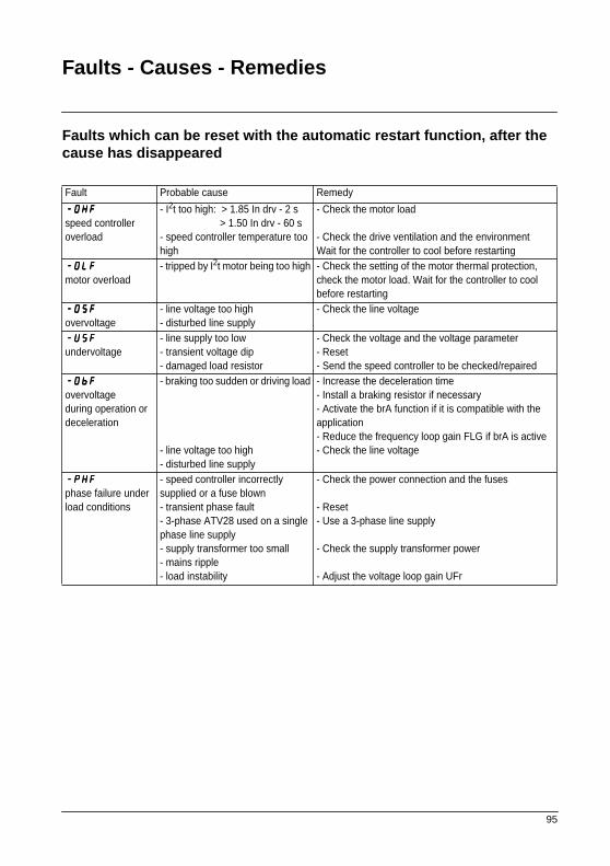
95
Faults - Causes - Remedies
Faults which can be reset with the automatic restart function, after the cause has disappeared
Fault Probable cause Remedy
----OOOOHHHHFFFF
speed controller overload
- I2t too high: > 1.85 In drv - 2 s > 1.50 In drv - 60 s- speed controller temperature too high
- Check the motor load
- Check the drive ventilation and the environmentWait for the controller to cool before restarting
----OOOOLLLLFFFF
motor overload- tripped by I2t motor being too high - Check the setting of the motor thermal protection,
check the motor load. Wait for the controller to cool before restarting
----OOOOSSSSFFFF
overvoltage- line voltage too high- disturbed line supply
- Check the line voltage
----UUUUSSSSFFFF
undervoltage- line supply too low- transient voltage dip- damaged load resistor
- Check the voltage and the voltage parameter- Reset- Send the speed controller to be checked/repaired
----OOOObbbbFFFF
overvoltage during operation or deceleration
- braking too sudden or driving load
- line voltage too high- disturbed line supply
- Increase the deceleration time- Install a braking resistor if necessary- Activate the brA function if it is compatible with the application- Reduce the frequency loop gain FLG if brA is active- Check the line voltage
----PPPPHHHHFFFF
phase failure under load conditions
- speed controller incorrectly supplied or a fuse blown- transient phase fault- 3-phase ATV28 used on a single phase line supply- supply transformer too small- mains ripple- load instability
- Check the power connection and the fuses
- Reset- Use a 3-phase line supply
- Check the supply transformer power
- Adjust the voltage loop gain UFr
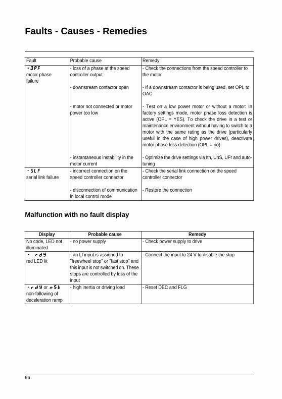
96
Faults - Causes - Remedies
Malfunction with no fault display
Fault Probable cause Remedy
----OOOOPPPPFFFF
motor phase failure
- loss of a phase at the speed controller output
- downstream contactor open
- motor not connected or motor power too low
- instantaneous instability in the motor current
- Check the connections from the speed controller to the motor - If a downstream contactor is being used, set OPL to OAC
- Test on a low power motor or without a motor: Infactory settings mode, motor phase loss detection isactive (OPL = YES). To check the drive in a test ormaintenance environment without having to switch to amotor with the same rating as the drive (particularlyuseful in the case of high power drives), deactivatemotor phase loss detection (OPL = no)
- Optimize the drive settings via Ith, UnS, UFr and auto-tuning
----SSSSLLLLFFFF
serial link failure- incorrect connection on the speed controller connector
- disconnection of communication in local control mode
- Check the serial link connection on the speed controller connector
- Restore the connection
Display Probable cause RemedyNo code, LED not illuminated
- no power supply - Check power supply to drive
---- rrrrddddYYYY
red LED lit- an LI input is assigned to "freewheel stop" or "fast stop" and this input is not switched on. These stops are controlled by loss of the input
- Connect the input to 24 V to disable the stop
----rrrrddddYYYY or nnnnSSSSttttnon-following of deceleration ramp
- high inertia or driving load - Reset DEC and FLG

97
Configuration/Settings Tables
Speed controller ATV-28 : .....................................................................................................................................Optional customer identification no. : ...................................................................................................................Software version (CPU parameter in the SUP menu) : .......................................................................................Optional access code : ..............................................................................................................................Local control option no y yes y
Menu (inputs/outputs)
Menu (drive)
Code Factory setting Customer setting Code Factory setting Customer setting
----ttttCCCCCCCC 2C ----LLLLIIII2222 rrS----LLLLIIII3333 PS2 ----LLLLIIII4444 PS4----AAAAIIIICCCC SAI ----CCCCrrrrLLLL 4 mA mA----CCCCrrrrHHHH 20 mA mA ----AAAAOOOO rFr----AAAAOOOOtttt 0 mA mA ----rrrr2222 SrA----AAAAdddddddd 1 ----bbbbddddrrrr 19.2
Code Factory setting Customer setting Code Factory setting Customer setting
----UUUUnnnnSSSS V V ----FFFFrrrrSSSS Hz Hz----ttttUUUUnnnn no ----ttttFFFFrrrr Hz Hz----UUUUFFFFtttt n ----bbbbrrrrAAAA YES----FFFFrrrrtttt 0 Hz Hz ----SSSSFFFFrrrr 4.0 kHz kHz----nnnnrrrrdddd YES ----AAAAttttrrrr no----OOOOPPPPLLLL YES ----IIIIPPPPLLLL YES----SSSSttttPPPP no ----FFFFLLLLrrrr no----ddddrrrrnnnn no ----SSSSddddSSSS 30
IIII----OOOO----
ddddrrrrCCCC----

98
Configuration/Settings Tables
Menu (settings)
Code Factory setting Customer setting Code Factory setting Customer setting
----rrrrPPPPIIII 0.0 % Control ----rrrrOOOOtttt For Control----AAAACCCCCCCC 3.0 s s ----ddddEEEECCCC 3.0 s s----AAAACCCC2222 5.0 s s ----ddddEEEE2222 5.0 s s----LLLLSSSSPPPP 0.0 Hz Hz ----HHHHSSSSPPPP Hz Hz----IIIIttttHHHH A A ----UUUUFFFFrrrr 20 % %----SSSSLLLLPPPP Hz Hz ----FFFFLLLLGGGG 33 % %----IIIIddddCCCC A A ----ttttddddCCCC 0.5 s s----JJJJPPPPFFFF 0 Hz Hz ----JJJJOOOOGGGG 10 Hz Hz----rrrrPPPPGGGG 1 ----rrrrIIIIGGGG 1 /s /s----FFFFbbbbSSSS 1 ----PPPPIIIICCCC no----SSSSPPPP2222 10 Hz Hz ----SSSSPPPP3333 15 Hz Hz----SSSSPPPP4444 20 Hz Hz ----SSSSPPPP5555 25 Hz Hz----SSSSPPPP6666 30 Hz Hz ----SSSSPPPP7777 35 Hz Hz----FFFFttttdddd Hz Hz ----CCCCttttdddd A A----ttttttttdddd 100 % % ----ttttLLLLSSSS 0.0 s s
The parameters in shaded boxes appear if the corresponding functions have been configured in the drC- or I-O- menus.
SSSSEEEEtttt----

99
Note

100
Note

!" () !"#$%&'()*+
!"E)
!"#$%
!"#$%&' 8
! 17
: 100004
: (010) 6590 6907
: (010) 6590 0013
!"
!"# 299
!"# A 9
: 200051
: (021) 6235 1333
: (021) 6235 1238
!"
! "# 403
!"#$% 31
: 510095
: (020) 8732 0138
: (020) 8732 1929
!"
!"#$%& 15
1502
: 430033
: (027) 8571 2588
: (027) 8571 2688
!"
!"#$%& 219
!"# 14 B, C
: 110015
: (024) 2396 4339
: (024) 2396 4296
!"#
!"#$%& 68
!" 1603
: 400010
: (023) 6383 9706
: (023) 6383 9707
!"
!"#$%&' 8
! 21
: 100004
: (010) 6590 6907
: (010) 6590 0986
!"
!"#$ 196
!"#$% 25
: 710061
: (029) 538 2880
: (029) 538 2890
!"
!"# 2
! 17 A
: 210016
: (025) 481 4815
: (025) 481 4816
!"
!"# 78
! 516
: 310003
: (0571) 8527 1304
: (0571) 8527 1305
!"
!"# 308
! 27 B, C, D
: 610017
: (028) 8652 8282
: (028) 8652 8383
!"#
!"#$%& 68
!"# 2205
: 116001
: (0411) 282 2690
: (0411) 282 2692
!"#$%
!"#$%& 5
!" 1112
: 830002
: (0991) 282 5888-1112
: (0991) 284 8188
!"#
!"#$%&125-127
! 1710-1711
: 300074
: (022) 2840 8408
: (022) 2840 8410
!"#
!"#$ 6
!"# A 2008
: 266071
: (0532) 591 9606
: (0532) 591 9607
!"#$ 66 !"
!"#$ B B 1107
: 250063
: (0531) 606 5156
: (0531) 606 5016
!"#$ 1104
!"# 918
: 230011
: (0551) 429 1993
: (0551) 429 1166-918
!
!"#$ 636
1 303
: 215005
: (0512) 6522 1287
: (0512) 6522 1287
!"#
!"#$ 19
!" 0601
: 361012
: (0592) 504 8393
: (0592) 504 8208
!"#
!"# 218
!" 519
: 350003
: (0591) 781 3070
: (0591) 781 2764
!"#
!"#$ 1
!"#$%& 833
: 315010
: (0574) 8771 6067
: (0574) 8772 4576
!"#
!"#$ 386
! 1200
: 410007
: (0731) 511 5858
: (0731) 511 7878
!"#
!"#$ 123
!"#$ 14 D
: 650032
: (0871) 364 7549
: (0871) 364 7552
!"#
!"#
!"#$% 17
: 518001
: (0755) 2584 1022
: (0755) 8208 0250
!"
! " 30
!" 31
3108-28
: (00852) 2565 0621
: (00852) 2811 1029
!"#$%
!"#$%&
!"#$%&'( 76 !"#$ 12 : 100086: (010) 6263 8210/11: (010) 6263 8212
!"#$%&'()
!"#$%&
!" 1954 !" !" ( !)
: 200030: (021) 62831227: (021) 62811847
800 810 1315010 6788 8904
!"#$%&:

2002.10
!"#$%&'(
!"#$
Schneider Electric Chinawww.schneider-electric.com.cn
!"#$%&' 8
! 17
:100004
:(010) 6590 6907
:(010) 6590 0013
17/F, Landmark Building
8 North Dongsanhuan Road
Chaoyang District Beijing 100004
Tel: (010) 6590 6907
Fax: (010) 6590 0013
!"#$%&'( !"#$%&'()*+,-./0(12
!"#$ !"#$%
!"#$%&'
SC DOC 293-VVD