altivar 66 haberleşme modbus en - inverter-plc.netŸme_modbus... · the user must supply the ......
TRANSCRIPT

ALTIVAR 66®
Modbus Plus® PCMCIA Communication Card Kit
VW3A66305U
User’s Manual
Instruction BulletinVD0C06S309
April 1997
efesotomasyon.com
Electrical equipment should be serviced only by qualified electrical maintenance personnel. No responsibility is assumed by Schneider S.A. for any consequences arising out of the use of this material.
© 1997 Schneider S.A. All rights reserved. This document may not be copied in whole or in part, or transferred to any other media, without the written permission of Schneider S.A.
ALTIVAR is a registered trademark of Square D.Modbus Plus is a registered trademark of Schneider Automation.
DANGERHAZARDOUS VOLTAGE• Before installing PCMCIA card or operating ALTIVAR 66 drive controller
with PCMCIA card installed, read and understand completely this and all other bulletins delivered with the ALTIVAR 66 drive controller and associated options. Installation, adjustment, repair, and maintenance of these drive controllers must be performed by qualified personnel.
• Disconnect all power before servicing drive controller. WAIT ONE MINUTE until DC bus capacitors discharge, then measure DC bus capacitor voltage between PA and (–) terminals to verify DC voltage is less than 45 V. The DC bus LED is not an accurate indication of the absence of DC bus voltage.
• DO NOT short across DC bus capacitors or touch unshielded components or terminal strip screw connections with voltage present.
• Install all covers and close door before applying power or starting and stopping the drive controller.
• User is responsible for conforming to all applicable code requirements with respect to grounding all equipment.
• Many parts in this drive controller, including printed wiring boards, operate at line voltage. DO NOT TOUCH. Use only electrically insulated tools.
Before servicing drive controller:• Disconnect all power.• Place a “DO NOT TURN ON” label on drive controller disconnect.• Lock disconnect in open position.Fail re to follow these instr ctions will res lt in death or serio s inj ry
efesotomasyon.com

VD0C06S309 VW3A66305U Modbus Plus PCMCIA Communication Card KitMay 2003 Table of Contents
i© 1997 Schneider S.A. All Rights Reserved
TABLE OF CONTENTS
INTRODUCTION . . . . . . . . . . . . . . . . . . . . . . . . . . . . . . . . . . . . . . . . . . . . . . . . . . . . . . . . . . . . . 1SYSTEM SAFETY CONSIDERATIONS . . . . . . . . . . . . . . . . . . . . . . . . . . . . . . . . . . . . . 2USING THIS MANUAL . . . . . . . . . . . . . . . . . . . . . . . . . . . . . . . . . . . . . . . . . . . . . . . . . . 2REVISION LEVEL . . . . . . . . . . . . . . . . . . . . . . . . . . . . . . . . . . . . . . . . . . . . . . . . . . . . . . 2
SECTION 1 — INSTALLATION & CONFIGURATION . . . . . . . . . . . . . . . . . . . . . . . . . . . . . . . . 3RECEIVING THE PCMCIA KIT . . . . . . . . . . . . . . . . . . . . . . . . . . . . . . . . . . . . . . . . . . . . 3COMMUNICATION INTERFACE SPECIFICATIONS . . . . . . . . . . . . . . . . . . . . . . . . . . . 3INSTALLING THE PCMCIA KIT . . . . . . . . . . . . . . . . . . . . . . . . . . . . . . . . . . . . . . . . . . . 3
Bus Voltage Measurement Procedure . . . . . . . . . . . . . . . . . . . . . . . . . . . . . . . . . . . 4Installing the Modbus Plus PCMCIA Kit . . . . . . . . . . . . . . . . . . . . . . . . . . . . . . . . . . 7
NETWORK OVERVIEW . . . . . . . . . . . . . . . . . . . . . . . . . . . . . . . . . . . . . . . . . . . . . . . . . 9Logical Network. . . . . . . . . . . . . . . . . . . . . . . . . . . . . . . . . . . . . . . . . . . . . . . . . . . . 11Physical Network. . . . . . . . . . . . . . . . . . . . . . . . . . . . . . . . . . . . . . . . . . . . . . . . . . . 12
CABLE ROUTING PRACTICES . . . . . . . . . . . . . . . . . . . . . . . . . . . . . . . . . . . . . . . . . . 12Environmental Requirements . . . . . . . . . . . . . . . . . . . . . . . . . . . . . . . . . . . . . . . . . 12
TRUNK AND DROP CABLING WITH TAPS . . . . . . . . . . . . . . . . . . . . . . . . . . . . . . . . . 13Routing Cables . . . . . . . . . . . . . . . . . . . . . . . . . . . . . . . . . . . . . . . . . . . . . . . . . . . . 14Mounting the Tap . . . . . . . . . . . . . . . . . . . . . . . . . . . . . . . . . . . . . . . . . . . . . . . . . . 15Connecting the Trunk Cables . . . . . . . . . . . . . . . . . . . . . . . . . . . . . . . . . . . . . . . . . 16
Modbus Plus Trunk Cable. . . . . . . . . . . . . . . . . . . . . . . . . . . . . . . . . . . . . . . . . 16Cable Entry and Jumpers (Taps at In-Line Sites) . . . . . . . . . . . . . . . . . . . . . . . 16Cable Entry and Jumpers (Taps at End Sites) . . . . . . . . . . . . . . . . . . . . . . . . . 16Connecting the Wires . . . . . . . . . . . . . . . . . . . . . . . . . . . . . . . . . . . . . . . . . . . . 17
Connecting the Drop Cable . . . . . . . . . . . . . . . . . . . . . . . . . . . . . . . . . . . . . . . . . . . 18Modbus Plus Drop Cable . . . . . . . . . . . . . . . . . . . . . . . . . . . . . . . . . . . . . . . . . 18Connecting the Signal Wires. . . . . . . . . . . . . . . . . . . . . . . . . . . . . . . . . . . . . . . 19Connecting the Drop Cable Drain Wire. . . . . . . . . . . . . . . . . . . . . . . . . . . . . . . 20
Grounding . . . . . . . . . . . . . . . . . . . . . . . . . . . . . . . . . . . . . . . . . . . . . . . . . . . . . . . . 20Labeling. . . . . . . . . . . . . . . . . . . . . . . . . . . . . . . . . . . . . . . . . . . . . . . . . . . . . . . . . . 20Checking the Cable Installation. . . . . . . . . . . . . . . . . . . . . . . . . . . . . . . . . . . . . . . . 20
Inspecting the Cable Installation . . . . . . . . . . . . . . . . . . . . . . . . . . . . . . . . . . . . 20Checking Cable Continuity . . . . . . . . . . . . . . . . . . . . . . . . . . . . . . . . . . . . . . . . 21
COMMUNICATION CONFIGURATION . . . . . . . . . . . . . . . . . . . . . . . . . . . . . . . . . . . . 22First Power Up. . . . . . . . . . . . . . . . . . . . . . . . . . . . . . . . . . . . . . . . . . . . . . . . . . . . . 22Communication Configuration Menu . . . . . . . . . . . . . . . . . . . . . . . . . . . . . . . . . . . . 23Diagnostics . . . . . . . . . . . . . . . . . . . . . . . . . . . . . . . . . . . . . . . . . . . . . . . . . . . . . . . 25Forced Local . . . . . . . . . . . . . . . . . . . . . . . . . . . . . . . . . . . . . . . . . . . . . . . . . . . . . . 26
efesotomasyon.com

VW3A66305U Modbus Plus PCMCIA Communication Card Kit VD0C06S309Table of Contents May 2003
© 1997 Schneider S.A. All Rights Reservedii
SECTION 2 — MODBUS PLUS OVERVIEW . . . . . . . . . . . . . . . . . . . . . . . . . . . . . . . . . . . . . . 27INTRODUCTION . . . . . . . . . . . . . . . . . . . . . . . . . . . . . . . . . . . . . . . . . . . . . . . . . . . . . . 27ALTIVAR 66 REGISTERS AND DATA EXCHANGE. . . . . . . . . . . . . . . . . . . . . . . . . . . 27
Messaging . . . . . . . . . . . . . . . . . . . . . . . . . . . . . . . . . . . . . . . . . . . . . . . . . . . . . . . . 27MSTR BLOCK . . . . . . . . . . . . . . . . . . . . . . . . . . . . . . . . . . . . . . . . . . . . . . . . . . . . . . . . 28
Overview of MSTR Block. . . . . . . . . . . . . . . . . . . . . . . . . . . . . . . . . . . . . . . . . . . . . 28MSTR Block Structure . . . . . . . . . . . . . . . . . . . . . . . . . . . . . . . . . . . . . . . . . . . . . . . 28
Inputs . . . . . . . . . . . . . . . . . . . . . . . . . . . . . . . . . . . . . . . . . . . . . . . . . . . . . . . . 28Outputs . . . . . . . . . . . . . . . . . . . . . . . . . . . . . . . . . . . . . . . . . . . . . . . . . . . . . . . 29Top Node Content . . . . . . . . . . . . . . . . . . . . . . . . . . . . . . . . . . . . . . . . . . . . . . . 29Middle Node Content . . . . . . . . . . . . . . . . . . . . . . . . . . . . . . . . . . . . . . . . . . . . 29Bottom Node Content . . . . . . . . . . . . . . . . . . . . . . . . . . . . . . . . . . . . . . . . . . . . 29
Read and Write MSTR Operations . . . . . . . . . . . . . . . . . . . . . . . . . . . . . . . . . . . . . 30Control Block. . . . . . . . . . . . . . . . . . . . . . . . . . . . . . . . . . . . . . . . . . . . . . . . . . . 30
PEER COP . . . . . . . . . . . . . . . . . . . . . . . . . . . . . . . . . . . . . . . . . . . . . . . . . . . . . . . . . . 30Global Data Transmission . . . . . . . . . . . . . . . . . . . . . . . . . . . . . . . . . . . . . . . . . . . . 33Command and Adjustment Semaphores. . . . . . . . . . . . . . . . . . . . . . . . . . . . . . . . . 34Example of Modbus Plus Network Operation . . . . . . . . . . . . . . . . . . . . . . . . . . . . . 34
OPTIMIZING NETWORK PERFORMANCE . . . . . . . . . . . . . . . . . . . . . . . . . . . . . . . . . 35DRIVE CONTROLLER COMMUNICATION PRINCIPLES . . . . . . . . . . . . . . . . . . . . . . 36
Data Structures . . . . . . . . . . . . . . . . . . . . . . . . . . . . . . . . . . . . . . . . . . . . . . . . . . . . 36Access to Data . . . . . . . . . . . . . . . . . . . . . . . . . . . . . . . . . . . . . . . . . . . . . . . . . . . . 36Units . . . . . . . . . . . . . . . . . . . . . . . . . . . . . . . . . . . . . . . . . . . . . . . . . . . . . . . . . . . . 36Range . . . . . . . . . . . . . . . . . . . . . . . . . . . . . . . . . . . . . . . . . . . . . . . . . . . . . . . . . . . 36Values at Power Up. . . . . . . . . . . . . . . . . . . . . . . . . . . . . . . . . . . . . . . . . . . . . . . . . 37Taking Command over the Network . . . . . . . . . . . . . . . . . . . . . . . . . . . . . . . . . . . . 37Parameter Types . . . . . . . . . . . . . . . . . . . . . . . . . . . . . . . . . . . . . . . . . . . . . . . . . . . 37Protection of Command Access . . . . . . . . . . . . . . . . . . . . . . . . . . . . . . . . . . . . . . . 38Protection of Adjustment Access. . . . . . . . . . . . . . . . . . . . . . . . . . . . . . . . . . . . . . . 38Data Priority. . . . . . . . . . . . . . . . . . . . . . . . . . . . . . . . . . . . . . . . . . . . . . . . . . . . . . . 38Access Protection by Forced Local . . . . . . . . . . . . . . . . . . . . . . . . . . . . . . . . . . . . . 38Command Mode Transitions . . . . . . . . . . . . . . . . . . . . . . . . . . . . . . . . . . . . . . . . . . 39Compatibility of Application Functions. . . . . . . . . . . . . . . . . . . . . . . . . . . . . . . . . . . 40
SECTION 3 — REGISTER DESCRIPTIONS. . . . . . . . . . . . . . . . . . . . . . . . . . . . . . . . . . . . . . . 41INTRODUCTION . . . . . . . . . . . . . . . . . . . . . . . . . . . . . . . . . . . . . . . . . . . . . . . . . . . . . . 41ADJUSTMENT REGISTERS (READ & WRITE) . . . . . . . . . . . . . . . . . . . . . . . . . . . . . . 42COMMAND REGISTERS (READ & WRITE). . . . . . . . . . . . . . . . . . . . . . . . . . . . . . . . . 44DISPLAY REGISTERS (READ ONLY) . . . . . . . . . . . . . . . . . . . . . . . . . . . . . . . . . . . . . 49
SECTION 4 — FAULT MANAGEMENT & NETWORK SECURITY . . . . . . . . . . . . . . . . . . . . . 63
APPENDIX A — ADDRESS DESCRIPTIONS & INDEX. . . . . . . . . . . . . . . . . . . . . . . . . . . . . . 67
INDEX. . . . . . . . . . . . . . . . . . . . . . . . . . . . . . . . . . . . . . . . . . . . . . . . . . . . . . . . . . . . . . . . . . . . . 73
efesotomasyon.com
VD0C06S309 VW3A66305U Modbus Plus PCMCIA Communication Card KitMay 2003 List of Figures
iii© 1997 Schneider S.A. All Rights Reserved
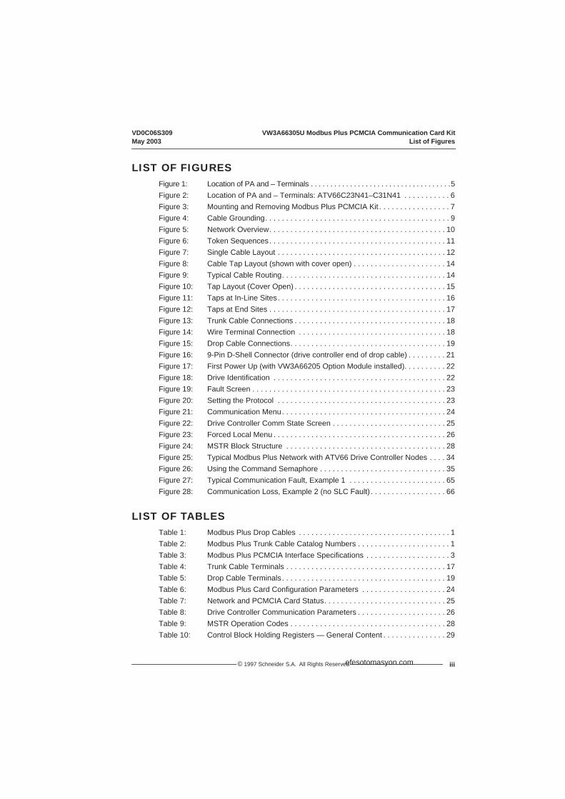
LIST OF FIGURESFigure 1: Location of PA and – Terminals . . . . . . . . . . . . . . . . . . . . . . . . . . . . . . . . . . . .5Figure 2: Location of PA and – Terminals: ATV66C23N41–C31N41 . . . . . . . . . . . 6Figure 3: Mounting and Removing Modbus Plus PCMCIA Kit . . . . . . . . . . . . . . . . . 7Figure 4: Cable Grounding. . . . . . . . . . . . . . . . . . . . . . . . . . . . . . . . . . . . . . . . . . . . 9Figure 5: Network Overview. . . . . . . . . . . . . . . . . . . . . . . . . . . . . . . . . . . . . . . . . . 10Figure 6: Token Sequences. . . . . . . . . . . . . . . . . . . . . . . . . . . . . . . . . . . . . . . . . . 11Figure 7: Single Cable Layout . . . . . . . . . . . . . . . . . . . . . . . . . . . . . . . . . . . . . . . . 12Figure 8: Cable Tap Layout (shown with cover open) . . . . . . . . . . . . . . . . . . . . . . 14Figure 9: Typical Cable Routing. . . . . . . . . . . . . . . . . . . . . . . . . . . . . . . . . . . . . . . 14Figure 10: Tap Layout (Cover Open) . . . . . . . . . . . . . . . . . . . . . . . . . . . . . . . . . . . . 15Figure 11: Taps at In-Line Sites. . . . . . . . . . . . . . . . . . . . . . . . . . . . . . . . . . . . . . . . 16Figure 12: Taps at End Sites . . . . . . . . . . . . . . . . . . . . . . . . . . . . . . . . . . . . . . . . . . 17Figure 13: Trunk Cable Connections . . . . . . . . . . . . . . . . . . . . . . . . . . . . . . . . . . . . 18Figure 14: Wire Terminal Connection . . . . . . . . . . . . . . . . . . . . . . . . . . . . . . . . . . . 18Figure 15: Drop Cable Connections. . . . . . . . . . . . . . . . . . . . . . . . . . . . . . . . . . . . . 19Figure 16: 9-Pin D-Shell Connector (drive controller end of drop cable) . . . . . . . . . 21Figure 17: First Power Up (with VW3A66205 Option Module installed). . . . . . . . . . 22Figure 18: Drive Identification . . . . . . . . . . . . . . . . . . . . . . . . . . . . . . . . . . . . . . . . . 22Figure 19: Fault Screen . . . . . . . . . . . . . . . . . . . . . . . . . . . . . . . . . . . . . . . . . . . . . . 23Figure 20: Setting the Protocol . . . . . . . . . . . . . . . . . . . . . . . . . . . . . . . . . . . . . . . . 23Figure 21: Communication Menu. . . . . . . . . . . . . . . . . . . . . . . . . . . . . . . . . . . . . . . 24Figure 22: Drive Controller Comm State Screen . . . . . . . . . . . . . . . . . . . . . . . . . . . 25Figure 23: Forced Local Menu . . . . . . . . . . . . . . . . . . . . . . . . . . . . . . . . . . . . . . . . . 26Figure 24: MSTR Block Structure . . . . . . . . . . . . . . . . . . . . . . . . . . . . . . . . . . . . . . 28Figure 25: Typical Modbus Plus Network with ATV66 Drive Controller Nodes . . . . 34Figure 26: Using the Command Semaphore . . . . . . . . . . . . . . . . . . . . . . . . . . . . . . 35Figure 27: Typical Communication Fault, Example 1 . . . . . . . . . . . . . . . . . . . . . . . 65Figure 28: Communication Loss, Example 2 (no SLC Fault) . . . . . . . . . . . . . . . . . . 66
LIST OF TABLESTable 1: Modbus Plus Drop Cables . . . . . . . . . . . . . . . . . . . . . . . . . . . . . . . . . . . . 1Table 2: Modbus Plus Trunk Cable Catalog Numbers . . . . . . . . . . . . . . . . . . . . . . 1Table 3: Modbus Plus PCMCIA Interface Specifications . . . . . . . . . . . . . . . . . . . . 3Table 4: Trunk Cable Terminals . . . . . . . . . . . . . . . . . . . . . . . . . . . . . . . . . . . . . . 17Table 5: Drop Cable Terminals . . . . . . . . . . . . . . . . . . . . . . . . . . . . . . . . . . . . . . . 19Table 6: Modbus Plus Card Configuration Parameters . . . . . . . . . . . . . . . . . . . . 24Table 7: Network and PCMCIA Card Status. . . . . . . . . . . . . . . . . . . . . . . . . . . . . 25Table 8: Drive Controller Communication Parameters . . . . . . . . . . . . . . . . . . . . . 26Table 9: MSTR Operation Codes . . . . . . . . . . . . . . . . . . . . . . . . . . . . . . . . . . . . . 28Table 10: Control Block Holding Registers — General Content . . . . . . . . . . . . . . . 29
efesotomasyon.com

VW3A66305U Modbus Plus PCMCIA Communication Card Kit VD0C06S309List of Tables May 2003
© 1997 Schneider S.A. All Rights Reservediv
Table 11: Control Block Registers — Read & Write Operations. . . . . . . . . . . . . . . 30Table 12: Command Registers Mapped with Peer Cop . . . . . . . . . . . . . . . . . . . . . 31Table 13: Adjustment Registers Mapped with Peer Cop [1, 2] . . . . . . . . . . . . . . . . 32Table 14: Display Parameters Mapping with Global Data . . . . . . . . . . . . . . . . . . . 33Table 15: Transition Between Command States . . . . . . . . . . . . . . . . . . . . . . . . . . 39Table 16: Compatibility of Application Functions . . . . . . . . . . . . . . . . . . . . . . . . . . 40Table 17: Adjustment Registers . . . . . . . . . . . . . . . . . . . . . . . . . . . . . . . . . . . . . . . 43Table 18: Command Registers . . . . . . . . . . . . . . . . . . . . . . . . . . . . . . . . . . . . . . . . 44Table 19: Freewheel & Fast Stop Selection . . . . . . . . . . . . . . . . . . . . . . . . . . . . . . 46Table 20: Multi-Motor or Multi-Parameter Selection . . . . . . . . . . . . . . . . . . . . . . . . 46Table 21: Additional Command Registers . . . . . . . . . . . . . . . . . . . . . . . . . . . . . . . 46Table 22: Limit Command Registers. . . . . . . . . . . . . . . . . . . . . . . . . . . . . . . . . . . . 47Table 23: Logic/Relay/Analog Output Command Registers . . . . . . . . . . . . . . . . . . 48Table 24: Analog Input Registers . . . . . . . . . . . . . . . . . . . . . . . . . . . . . . . . . . . . . . 49Table 25: Power, Voltage, & Thermal State Registers . . . . . . . . . . . . . . . . . . . . . . 50Table 26: Frequency, Current, Torque, & Speed Registers . . . . . . . . . . . . . . . . . . 50Table 27: Fault Registers & SLC/Local . . . . . . . . . . . . . . . . . . . . . . . . . . . . . . . . . 51Table 28: Drive Controller Status Registers . . . . . . . . . . . . . . . . . . . . . . . . . . . . . . 52Table 29: Multi-Motor or Multi-Parameter Set Selected . . . . . . . . . . . . . . . . . . . . . 52Table 30: Additional Drive Controller Status Registers . . . . . . . . . . . . . . . . . . . . . . 53Table 31: Motor/Parameter Set, Cycle, Preset Speed . . . . . . . . . . . . . . . . . . . . . . 54Table 32: Drive Controller Horsepower. . . . . . . . . . . . . . . . . . . . . . . . . . . . . . . . . . 54Table 33: Status of Options (cards, modules, keypad) . . . . . . . . . . . . . . . . . . . . . . 55Table 34: Command Node Status. . . . . . . . . . . . . . . . . . . . . . . . . . . . . . . . . . . . . . 55Table 35: Token & Message Status . . . . . . . . . . . . . . . . . . . . . . . . . . . . . . . . . . . . 55Table 36: Elapsed Time, Output Speed, & Machine Frequency. . . . . . . . . . . . . . . 55Table 37: Analog Output Assignment and Value . . . . . . . . . . . . . . . . . . . . . . . . . . 56Table 38: LIx/LOx/ROx State . . . . . . . . . . . . . . . . . . . . . . . . . . . . . . . . . . . . . . . . . 57Table 39: LOx/ROx Assignment . . . . . . . . . . . . . . . . . . . . . . . . . . . . . . . . . . . . . . . 58Table 40: Logic Input Assignments. . . . . . . . . . . . . . . . . . . . . . . . . . . . . . . . . . . . . 59Table 41: Fault Register (Fault that Caused Drive Controller to Trip). . . . . . . . . . . 60Table 42: Present Faults Register (Fault Present if bit = 1) . . . . . . . . . . . . . . . . . . 61Table 43: Fault History . . . . . . . . . . . . . . . . . . . . . . . . . . . . . . . . . . . . . . . . . . . . . . 62Table 44: Drive Controller Response to Loss of Node . . . . . . . . . . . . . . . . . . . . . . 64Table 45: Other Typical Fault Conditions . . . . . . . . . . . . . . . . . . . . . . . . . . . . . . . . 64
efesotomasyon.com
VD0C06S309 IntroductionMay 2003 Modbus Plus® PCMCIA Communication Card Kit
1© 1997 Schneider S.A. All Rights Reserved
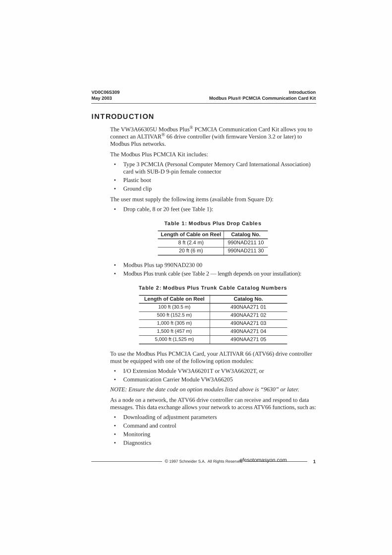
INTRODUCTION
The VW3A66305U Modbus Plus® PCMCIA Communication Card Kit allows you to connect an ALTIVAR® 66 drive controller (with firmware Version 3.2 or later) to Modbus Plus networks.
The Modbus Plus PCMCIA Kit includes:
• Type 3 PCMCIA (Personal Computer Memory Card International Association) card with SUB-D 9-pin female connector
• Plastic boot• Ground clip
The user must supply the following items (available from Square D):
• Drop cable, 8 or 20 feet (see Table 1):
• Modbus Plus tap 990NAD230 00• Modbus Plus trunk cable (see Table 2 — length depends on your installation):
To use the Modbus Plus PCMCIA Card, your ALTIVAR 66 (ATV66) drive controller must be equipped with one of the following option modules:
• I/O Extension Module VW3A66201T or VW3A66202T, or• Communication Carrier Module VW3A66205
NOTE: Ensure the date code on option modules listed above is “9630” or later.
As a node on a network, the ATV66 drive controller can receive and respond to data messages. This data exchange allows your network to access ATV66 functions, such as:
• Downloading of adjustment parameters• Command and control• Monitoring• Diagnostics
Table 1: Modbus Plus Drop Cables
Length of Cable on Reel Catalog No.8 ft (2.4 m) 990NAD211 1020 ft (6 m) 990NAD211 30
Table 2: Modbus Plus Trunk Cable Catalog Numbers
Length of Cable on Reel Catalog No.100 ft (30.5 m) 490NAA271 01500 ft (152.5 m) 490NAA271 021,000 ft (305 m) 490NAA271 031,500 ft (457 m) 490NAA271 04
5,000 ft (1,525 m) 490NAA271 05
efesotomasyon.com
Introduction VD0C06S309Using This Manual May 2003
2 © 1997 Schneider S.A. All Rights Reserved
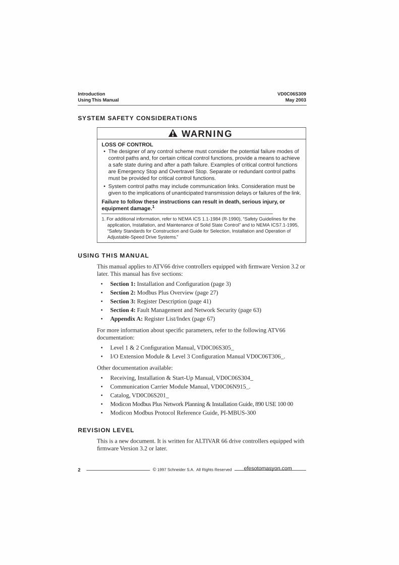
SYSTEM SAFETY CONSIDERATIONS
USING THIS MANUAL
This manual applies to ATV66 drive controllers equipped with firmware Version 3.2 or later. This manual has five sections:
• Section 1: Installation and Configuration (page 3) • Section 2: Modbus Plus Overview (page 27) • Section 3: Register Description (page 41) • Section 4: Fault Management and Network Security (page 63) • Appendix A: Register List/Index (page 67)
For more information about specific parameters, refer to the following ATV66 documentation:
• Level 1 & 2 Configuration Manual, VD0C06S305_• I/O Extension Module & Level 3 Configuration Manual VD0C06T306_.
Other documentation available:
• Receiving, Installation & Start-Up Manual, VD0C06S304_• Communication Carrier Module Manual, VD0C06N915_.• Catalog, VD0C06S201_• Modicon Modbus Plus Network Planning & Installation Guide, 890 USE 100 00• Modicon Modbus Protocol Reference Guide, PI-MBUS-300
REVISION LEVEL
This is a new document. It is written for ALTIVAR 66 drive controllers equipped with firmware Version 3.2 or later.
LOSS OF CONTROL• The designer of any control scheme must consider the potential failure modes of
control paths and, for certain critical control functions, provide a means to achieve a safe state during and after a path failure. Examples of critical control functions are Emergency Stop and Overtravel Stop. Separate or redundant control paths must be provided for critical control functions.
• System control paths may include communication links. Consideration must be given to the implications of unanticipated transmission delays or failures of the link.
Failure to follow these instructions can result in death, serious injury, or equipment damage.1
1. For additional information, refer to NEMA ICS 1.1-1984 (R-1990), “Safety Guidelines for the application, Installation, and Maintenance of Solid State Control” and to NEMA ICS7.1-1995, “Safety Standards for Construction and Guide for Selection, Installation and Operation of Adjustable-Speed Drive Systems.”
WARNING
efesotomasyon.com

VD0C06S309 Section 1 — Installation & ConfigurationMay 2003 Receiving & Installing the PCMCIA Kit
3© 1997 Schneider S.A. All Rights Reserved
SECTION 1 — INSTALLATION & CONFIGURATION
RECEIVING THE PCMCIA KIT
Remove the Modbus Plus PCMCIA Kit from its packaging and visually inspect it for shipping damage. If any damage is found, notify the carrier and your local Square D representative. Do not install a damaged card. To store the PCMCIA card, replace it in its original packing material and store at -40 to +185 °F (-40 to +85 °C).
COMMUNICATION INTERFACE SPECIFICATIONS
INSTALLING THE PCMCIA KIT
Before installing, removing, or replacing the Modbus Plus PCMCIA Kit, remove all power from the drive controller, including external control power that may be present on the option module, and perform the “Bus Voltage Measurement Procedure” on page 4.
Table 3: Modbus Plus PCMCIA Interface Specifications
Isolation (network to drive controller) Galvanically isolated for 30 V RMS, 50 V peakIsolation (cable jacket to ground) 150 V RMSPCMCIA connector 9-pin, female D-shellElectrical interface RS-485Storage temperature -40 to 185 °F (-40 to +85 °C)Operating temperature Same as drive controller. See VD0C06S304_.
Humidity 95% relative humidity at +140 °F (+60 °C), non-condensing
Altitude Up to 15,000 ft (4,500 m)Shock (non-operating) 30 g for 11 ms (three shocks/axis)Shock (operating) Same as drive controller. See VD0C06S304_.
UNINTENDED EQUIPMENT ACTIONRead and understand this document, VD0C06S304_, VD0C06S305_, and manual for applicable option module before operating drive controller.Failure to follow these instructions can result in death, serious injury, or equipment damage.
WARNING
efesotomasyon.com
Section 1 — Installation & Configuration VD0C06S309Bus Voltage Measurement Procedure May 2003
4 © 1997 Schneider S.A. All Rights Reserved
Bus Voltage Measurement Procedure
The PA and – terminals are located inside the drive controller (see Figure 1). To measure bus capacitor voltage:
1. Disconnect all power from the drive controller.2. Wait 1 minute to allow the DC bus to discharge.3. Open the front cover of the drive controller.4. Set the voltmeter to the 1000 VDC scale. Measure the bus capacitor voltage
between the PA and – terminals to verify that the DC voltage is less than 45 V. Donot short across capacitor terminals with voltage present!
5. If the bus capacitors are not fully discharged, contact your local Square D representative. Do do not operate the drive controller.
DANGERHAZARDOUS VOLTAGE• Drive controller contains energy storage devices. Read and understand Bus Voltage
Measurement Procedure before installing PCMCIA Communication Card Kit. Measurement of DC bus capacitor voltage must be performed by qualified personnel.
• DC bus LED is not an accurate indication of absence of DC bus voltage.• DO NOT short across capacitors or touch unshielded components or terminal strip
screw connections with voltage present.• Many parts in this drive controller, including printed wiring boards, operate at line
voltage. DO NOT TOUCH. Use only electrically insulated tools.Failure to follow these instructions will cause shock or burn, resulting in death or serious injury.
efesotomasyon.com

VD0C06S309 Section 1 — Installation & ConfigurationMay 2003 Bus Voltage Measurement Procedure
5© 1997 Schneider S.A. All Rights Reserved
Figure 1: Location of PA and – Terminals: ATV66U41N4 to C19N4 and ATV66U41M2 to D46M2
AI2-U
AI2-I
F4
ProtectiveSwitch(GV2)
PA—
AI2-U
AI2-I
J13 J12
J2
PA—
ATV66U41N4 to D12N4 and
ATV66D16N4 to D79N4 and
ATV66C10N4 to C19N4
ATV66U41M2 to U90M2
ATV66D12M2 to D46M2
DC BusLED
DC BusLED
AI2-U
AI2-I
PA—
DC BusLED
efesotomasyon.com

Section 1 — Installation & Configuration VD0C06S309Bus Voltage Measurement Procedure May 2003
6 © 1997 Schneider S.A. All Rights Reserved
Figure 2: Location of PA and – Terminals: ATV66C23N41 to C31N41
4
DANGER
PB PA–
L2 L3L1PA
—
F5
F6
NOTICE
F4A F4B F4C
DC BusLED
efesotomasyon.com

VD0C06S309 Section 1 — Installation & ConfigurationMay 2003 Installing the Modbus Plus PCMCIA Kit
7© 1997 Schneider S.A. All Rights Reserved
Installing the Modbus Plus PCMCIA KitTo install the Modbus Plus PCMCIA Kit into the drive controller:
1. Open the drive controller door.2. On models ATV66U41N4 to D12N4 and ATV66U41M2 to U90M2, remove the
plastic knockout from the top of drive controller cover.NOTE: The drive controller enclosure Type rating will change from Type 1 to Open when the knockout is removed.
3. Remove protective label from PCMCIA slot of option module4. Install the plastic boot supplied with the Modbus Plus PCMCIA kit onto separately
ordered cable (see Figure 3). Install cable onto 9-pin D-shell connector of the PCMCIA card.NOTE: Plastic boot must be installed to maintain ESD rating of drive controller.
5. Insert the PCMCIA card 68-pin connector into the PCMCIA slot on top of option card with the “Insert” arrows facing toward the front of drive controller (see Figure 3). Seat the plastic boot over the end of the PCMCIA card as shown.
Figure 3: Mounting and Removing Modbus Plus PCMCIA Kit
PlasticKnockout
To remove PCMCIA Card, push eject button on option card
Plastic Boot
User-provided cable (see page 1)
efesotomasyon.com
Section 1 — Installation & Configuration VD0C06S309Installing the Modbus Plus PCMCIA Kit May 2003
8 © 1997 Schneider S.A. All Rights Reserved
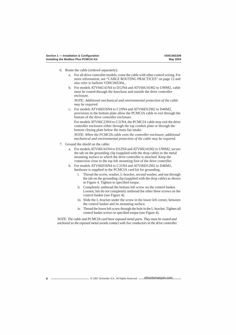
6. Route the cable (ordered separately):a. For all drive controller models, route the cable with other control wiring. For
more information, see “CABLE ROUTING PRACTICES” on page 12 and also refer to bulletin VD0C06S304_.
b. For models ATV66U41N4 to D12N4 and ATV66U41M2 to U90M2, cable must be routed through the knockout and outside the drive controller enclosure.NOTE: Additional mechanical and environmental protection of the cable may be required.
c. For models ATV66D16N4 to C19N4 and ATV66D12M2 to D46M2, provisions in the bottom plate allow the PCMCIA cable to exit through the bottom of the drive controller enclosure.For models ATV66C23N4 to C31N4, the PCMCIA cable may exit the drive controller enclosure either through the top conduit plate or through the bottom closing plate below the main fan intake.NOTE: When the PCMCIA cable exits the controller enclosure, additional mechanical and environmental protection of the cable may be required.
7. Ground the shield on the cable:a. For models ATV66U41N4 to D12N4 and ATV66U41M2 to U90M2, secure
the tab on the grounding clip (supplied with the drop cable) to the metal mounting surface to which the drive controller is attached. Keep the connection close to the top left mounting foot of the drive controller.
b. For models ATV66D16N4 to C31N4 and ATV66D12M2 to D46M2, hardware is supplied in the PCMCIA card kit for grounding.
i. Thread the screw, washer, L-bracket, second washer, and nut through the tab on the grounding clip (supplied with the drop cable) as shown in Figure 4. Tighten to specified torque.
ii. Completely unthread the bottom left screw on the control basket. Loosen, but do not completely unthread the other three screws on the control basket (see Figure 4).
iii. Slide the L-bracket under the screw in the lower left corner, between the control basket and its mounting surface.
iv. Thread the lower left screw through the hole in the L-bracket. Tighten all control basket screws to specified torque (see Figure 4).
NOTE: The cable and PCMCIA card have exposed metal parts. They must be routed and anchored so the exposed metal avoids contact with live conductors in the drive controller.
efesotomasyon.com
VD0C06S309 Section 1 — Installation & ConfigurationMay 2003 Network Overview
9© 1997 Schneider S.A. All Rights Reserved
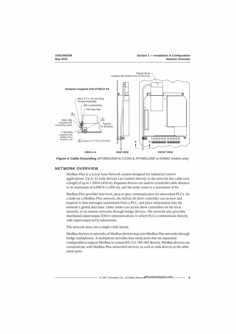
Figure 4: Cable Grounding (ATV66D16N4 to C31N4 & ATV66D12M2 to D46M2 models only)
NETWORK OVERVIEWModbus Plus is a Local Area Network system designed for industrial control applications. Up to 32 node devices can connect directly to the network bus cable over a length of up to 1,500 ft (450 m). Repeater devices are used to extend the cable distance to its maximum of 6,000 ft (1,800 m), and the node count to a maximum of 64.
Modbus Plus provides host level, peer-to-peer communication for networked PLCs. As a node on a Modbus Plus network, the Altivar 66 drive controller can receive and respond to data messages transmitted from a PLC, and place information into the network’s global data base. Other nodes can access drive controllers on the local network, or on remote networks through bridge devices. The network also provides distributed input/output (DIO) communications in which PLCs communicate directly with input/output (I/O) subsystems.
The network must use a single-cable layout.
Modbus devices or networks of Modbus devices may join Modbus Plus networks through bridge multiplexers. A multiplexer provides four serial ports that are separately configurable to support Modbus or custom RS-232 / RS-485 devices. Modbus devices can communicate with Modbus Plus networked devices, as well as with devices at the other serial ports.
Hardware Supplied with PCMCIA Kit
M4 x 0.7 x 10 mm long Screw Assembly
M4 Lockwasher
Typical(4 Screws)
M4 Hex Nut
Wire Clip (supplied with
connecting cable)
L-Bracket(supplied with Modbus Plus PCMCIA kit)
VIEW A–A
Plastic Boot(supplied with Modbus Plus PCMCIA kit)
A A
1
1
Torque: 17.7 lb-in (2.0 N•m)1
FRONT VIEWSIDE VIEW
efesotomasyon.com
Section 1 — Installation & Configuration VD0C06S309Network Overview May 2003
10 © 1997 Schneider S.A. All Rights Reserved
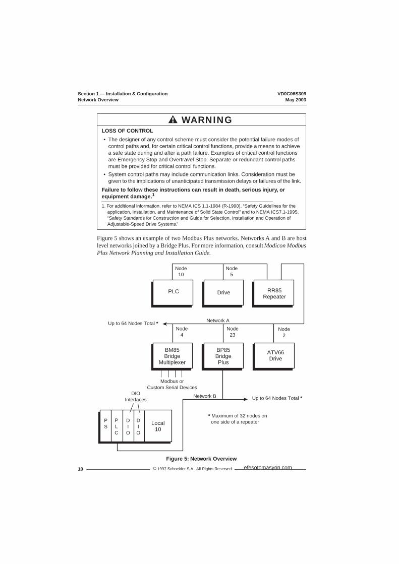
Figure 5 shows an example of two Modbus Plus networks. Networks A and B are hostlevel networks joined by a Bridge Plus. For more information, consult Modicon ModbusPlus Network Planning and Installation Guide.
Figure 5: Network Overview
LOSS OF CONTROL• The designer of any control scheme must consider the potential failure modes of
control paths and, for certain critical control functions, provide a means to achieve a safe state during and after a path failure. Examples of critical control functions are Emergency Stop and Overtravel Stop. Separate or redundant control paths must be provided for critical control functions.
• System control paths may include communication links. Consideration must be given to the implications of unanticipated transmission delays or failures of the link.
Failure to follow these instructions can result in death, serious injury, or equipment damage.1
1. For additional information, refer to NEMA ICS 1.1-1984 (R-1990), “Safety Guidelines for the application, Installation, and Maintenance of Solid State Control” and to NEMA ICS7.1-1995, “Safety Standards for Construction and Guide for Selection, Installation and Operation of Adjustable-Speed Drive Systems.”
WARNING
Up to 64 Nodes Total *
Up to 64 Nodes Total *
Node10
Node5
Node4
Node23
Node2
Network B
Network A
Modbus orCustom Serial Devices
DIOInterfaces
PLC Drive
ATV66Drive
RR85Repeater
BM85Bridge
Multiplexer
BP85BridgePlus
Local10
PLC
DIO
DIO
PS
* Maximum of 32 nodes on one side of a repeater
efesotomasyon.com
VD0C06S309 Section 1 — Installation & ConfigurationMay 2003 Network Overview
11© 1997 Schneider S.A. All Rights Reserved
Logical NetworkNetwork nodes are identified by user-assigned addresses. Each node’s address is independent of its physical site location. Addresses must be within the range of 1 to 64 decimal, although they do not have to be sequential. Duplicate addresses are not allowed. A device with a duplicate address will not be allowed to join the network. If it attempts to join the network, it will display an LED pattern for duplicate address.
The token is a grouping of bits that is passed in rotating address sequence from one node to another. Network nodes function as peer members of a logical ring, gaining access to the network upon receipt of a token frame. Each network maintains its own token rotation sequence, independent of other networks. Where multiple networks are joined by bridges, the token is not passed through the bridge device.
While holding the token, a node initiates message transactions with other nodes. Each message contains routing fields defining its source and destination, including its routing path through bridges to the final destination on a remote network.
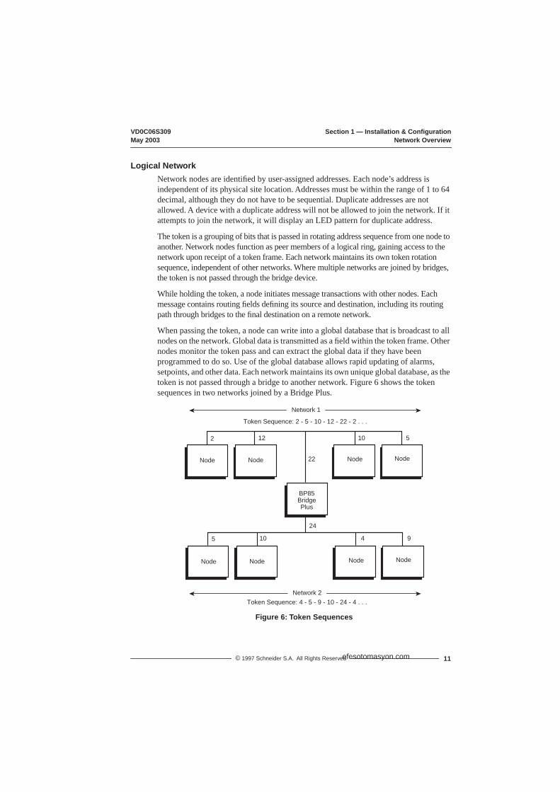
When passing the token, a node can write into a global database that is broadcast to all nodes on the network. Global data is transmitted as a field within the token frame. Other nodes monitor the token pass and can extract the global data if they have been programmed to do so. Use of the global database allows rapid updating of alarms, setpoints, and other data. Each network maintains its own unique global database, as the token is not passed through a bridge to another network. Figure 6 shows the token sequences in two networks joined by a Bridge Plus.
Figure 6: Token Sequences
Token Sequence: 2 - 5 - 10 - 12 - 22 - 2 . . .
BP85BridgePlus
BP85BridgePlus
Token Sequence: 4 - 5 - 9 - 10 - 24 - 4 . . .
Network 1
Network 2
2 12 10 5
5 10 4 9
22
24
Node
BP85BridgePlus
Node Node Node
Node Node Node Node
efesotomasyon.com

Section 1 — Installation & Configuration VD0C06S309Network Overview May 2003
12 © 1997 Schneider S.A. All Rights Reserved
Physical NetworkThe network bus consists of twisted-pair shielded cable that is run in a direct path between successive nodes. The two data lines in the cable are not sensitive to polarity; however, a standard wiring convention is followed in this bulletin to facilitate maintenance.
The physical network consists of one or more cable sections, with any section supporting up to 32 nodes at a maximum cable distance of 1,500 ft (450 m). Sections can be joined by repeater devices to extend the network’s length and to support up to 64 nodes. The minimum cable length between any pair of nodes must be at least 10 ft (3 m). The maximum cable length between two nodes is the same as the maximum section length of 1,500 ft (450 m).
NOTE: The ATV66 drive controller does not support a dual or redundant cable layout.
Figure 7: Single Cable Layout
NOTE: For information on jumpers, refer to Figure 8 on page 14.
CABLE ROUTING PRACTICES
Environmental RequirementsAvoid areas of high temperature, moisture, vibration, or other mechanical stress. Secure the cable where necessary to prevent its weight and the weight of other cables from pulling or twisting the cable. Use cable ducts, raceways, or other structures for protecting the cable. These structures should be used for signal wiring paths, and should not contain power wiring.
Avoid sources of electrical interference that can induce noise into the cable. Use the maximum practicable separation from such sources.
BP85BridgePlus
= Jumpers Connected
EndNode
InlineNode
InlineNode
ATV66Drive
= Jumpers Disconnected
10 ft (3 m) Cable Min.
Up to 32 Nodes Max.; 1500 ft (450 m) Cable Max.
CableTaps
efesotomasyon.com
VD0C06S309 Section 1 — Installation & ConfigurationMay 2003 Trunk and Drop Cabling with Taps
13© 1997 Schneider S.A. All Rights Reserved
When planning cable routing within a building, follow these guidelines:
• Maintain a minimum separation of 3.3 ft (1 m) from the following equipment: air conditioners, elevators, escalators, large blowers, radios, televisions, intercom and security systems, fluorescent, incandescent and neon lighting fixtures.
• Maintain a minimum separation of 10 ft (3 m) from the following equipment: power wiring, transformers, generators, and alternators.
When wiring in electrical equipment rooms or large electrical equipment line-ups, observe the following guidelines for cable segregation and separation of circuits:
• Use metallic conduit for a drive controller wiring. Do not run control network and power wiring in the same conduit.
• Separate non-metallic conduits or cable trays used to carry power wiring from metallic conduit carrying low-level control network wiring by at least 12 in (305 mm).
• Separate metallic conduits carrying power wiring or low-level control network wiring by at least 3 in (80 mm).
• Cross the metallic conduits and non-metallic conduits at right angles whenever power and control network wiring cross.
• Attenuate conducted emissions to the line from the drive controller in some installations to prevent interference with telecommunication, radio, and sensitive electronic equipment. Such instances may require attenuating filters. Consult catalog for selection and application of these filters.
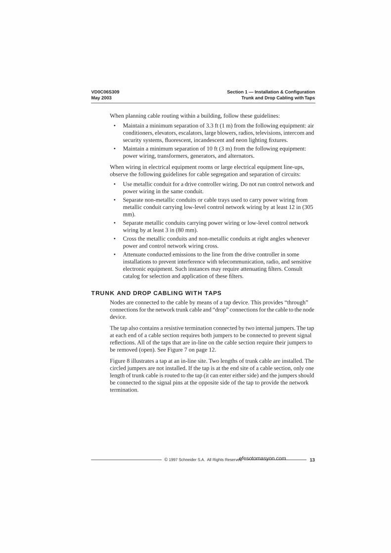
TRUNK AND DROP CABLING WITH TAPSNodes are connected to the cable by means of a tap device. This provides “through” connections for the network trunk cable and “drop” connections for the cable to the node device.
The tap also contains a resistive termination connected by two internal jumpers. The tap at each end of a cable section requires both jumpers to be connected to prevent signal reflections. All of the taps that are in-line on the cable section require their jumpers to be removed (open). See Figure 7 on page 12.
Figure 8 illustrates a tap at an in-line site. Two lengths of trunk cable are installed. The circled jumpers are not installed. If the tap is at the end site of a cable section, only one length of trunk cable is routed to the tap (it can enter either side) and the jumpers should be connected to the signal pins at the opposite side of the tap to provide the network termination.
efesotomasyon.com
Section 1 — Installation & Configuration VD0C06S309Trunk and Drop Cabling with Taps May 2003
14 © 1997 Schneider S.A. All Rights Reserved
Figure 8: Cable Tap Layout (shown with cover open)
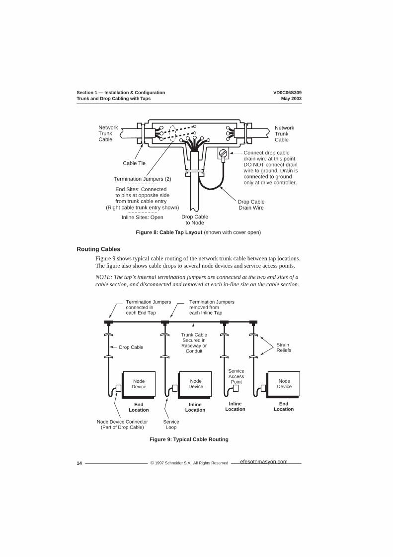
Routing CablesFigure 9 shows typical cable routing of the network trunk cable between tap locations. The figure also shows cable drops to several node devices and service access points.
NOTE: The tap’s internal termination jumpers are connected at the two end sites of a cable section, and disconnected and removed at each in-line site on the cable section.
Figure 9: Typical Cable Routing
NetworkTrunkCable
NetworkTrunkCable
Drop Cableto Node
Cable Tie
Drop Cable Drain Wire
Termination Jumpers (2)
End Sites: Connectedto pins at opposite sidefrom trunk cable entry
(Right cable trunk entry shown)
Inline Sites: Open
Connect drop cable drain wire at this point. DO NOT connect drain wire to ground. Drain is connected to ground only at drive controller.
NodeDevice
NodeDevice
ServiceAccessPoint Node
Device
Termination Jumpersconnected ineach End Tap
EndLocation
Drop Cable
Trunk CableSecured inRaceway or
ConduitStrainReliefs
InlineLocation
EndLocation
InlineLocation
Node Device Connector(Part of Drop Cable)
ServiceLoop
Termination Jumpersremoved fromeach Inline Tap
efesotomasyon.com
VD0C06S309 Section 1 — Installation & ConfigurationMay 2003 Trunk and Drop Cabling with Taps
15© 1997 Schneider S.A. All Rights Reserved
Referring to Figure 9, route the cable between the site locations of the node devices. Guidelines for cable routing are described below.
• Use a continuous length of trunk cable between locations. Do not use any splices.• At each tap location, allow sufficient trunk cable length for a service loop to
prevent pulling or twisting the cable.• For each drop cable, provide a service loop to allow the connector to be connected
and disconnected at the network node device without any strain on the cable. A service loop of 6 in (152 mm) minimum radius is adequate for most installations.
• Install cable ties or clamps on each trunk cable segment as required for strain reliefs, to prevent the cable from pulling on the tap.
• Install cable ties or clamps on each drop cable as required for strain reliefs, to prevent the cable from pulling on the tap or node device connector.
• Use additional ties or clamps as required to secure each cable from flexing or other damage in areas of mechanical motion devices and traffic.
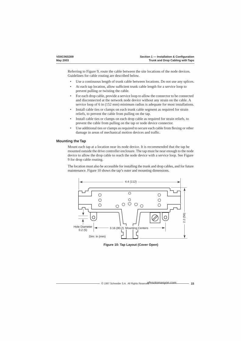
Mounting the TapMount each tap at a location near its node device. It is recommended that the tap be mounted outside the drive controller enclosure. The tap must be near enough to the node device to allow the drop cable to reach the node device with a service loop. See Figure 9 for drop cable routing.
The location must also be accessible for installing the trunk and drop cables, and for future maintenance. Figure 10 shows the tap’s outer and mounting dimensions.
Figure 10: Tap Layout (Cover Open)
4.4 (112)
Hole Diameter0.2 (5) 3.16 (80.2)
2.2
(56)
Dim: in (mm)
Mounting Centers
efesotomasyon.com
Section 1 — Installation & Configuration VD0C06S309Trunk and Drop Cabling with Taps May 2003
16 © 1997 Schneider S.A. All Rights Reserved
Connecting the Trunk Cables
Modbus Plus Trunk CableCable specified for Modbus Plus trunk use is available from Square D. See Table 2 on page 1.
Your cable should run directly between the network device locations. Each cable segment must be a continuous run between the taps at two locations. Do not use splices, splitters, or any other configurations such as star or tree configurations. The only allowed media components are the network cable and taps.
Plan cable runs according to the horizontal distances between sites. Trunk cable is ordered in reels of fixed length. Order reels of sufficient length to allow continuous runs between the network devices.
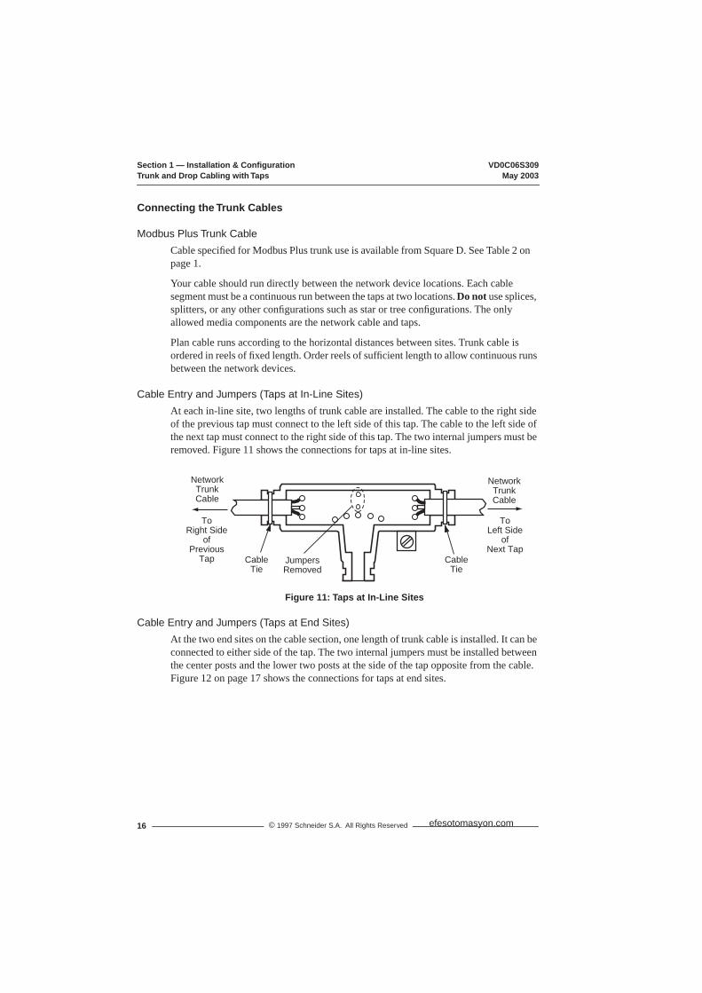
Cable Entry and Jumpers (Taps at In-Line Sites)At each in-line site, two lengths of trunk cable are installed. The cable to the right side of the previous tap must connect to the left side of this tap. The cable to the left side of the next tap must connect to the right side of this tap. The two internal jumpers must be removed. Figure 11 shows the connections for taps at in-line sites.
Figure 11: Taps at In-Line Sites
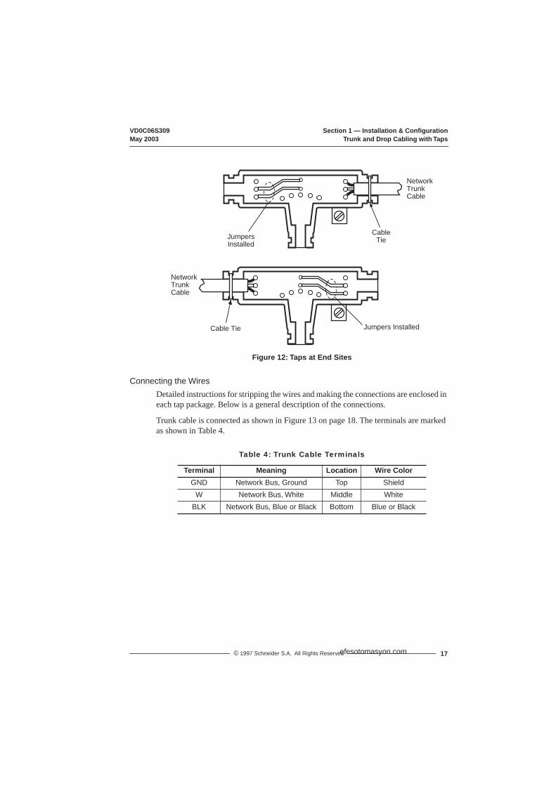
Cable Entry and Jumpers (Taps at End Sites)At the two end sites on the cable section, one length of trunk cable is installed. It can be connected to either side of the tap. The two internal jumpers must be installed between the center posts and the lower two posts at the side of the tap opposite from the cable. Figure 12 on page 17 shows the connections for taps at end sites.
NetworkTrunkCable
NetworkTrunkCable
CableTie
JumpersRemoved
CableTie
ToRight Side
ofPrevious
Tap
ToLeft Side
ofNext Tap
efesotomasyon.com
VD0C06S309 Section 1 — Installation & ConfigurationMay 2003 Trunk and Drop Cabling with Taps
17© 1997 Schneider S.A. All Rights Reserved
Figure 12: Taps at End Sites
Connecting the WiresDetailed instructions for stripping the wires and making the connections are enclosed in each tap package. Below is a general description of the connections.
Trunk cable is connected as shown in Figure 13 on page 18. The terminals are marked as shown in Table 4.
Table 4: Trunk Cable Terminals
Terminal Meaning Location Wire ColorGND Network Bus, Ground Top Shield
W Network Bus, White Middle WhiteBLK Network Bus, Blue or Black Bottom Blue or Black
NetworkTrunkCable
Cable Tie Jumpers Installed
NetworkTrunkCable
JumpersInstalled
CableTie
efesotomasyon.com

Section 1 — Installation & Configuration VD0C06S309Trunk and Drop Cabling with Taps May 2003
18 © 1997 Schneider S.A. All Rights Reserved
Figure 13: Trunk Cable Connections
To connect each wire:
1. Remove the plastic cap from the terminal.2. Place the wire into the terminal slot.3. Using a Phillips screwdriver, press the cap into the terminal to force the wire down
into the slot.
Figure 14 shows the connection sequence. A special tool is available for making these connections (AMP part number 552714-3).
Figure 14: Wire Terminal Connection
Connecting the Drop Cable
Modbus Plus Drop CableA drop cable is used at each site to connect between the tap and a network node device. The cable is preassembled with a 9-pin D connector on one end for connection to the node device. The other end is open for connection to the taps. Cables are available in two lengths (see Table 1 on page 1).
Order a sufficient quantity of drop cables and taps to allow extra ones for service access and spares.
GND
W
BLK
GND
W
BLK
CableTie
CableTie
1 2 3
CapTerminal
efesotomasyon.com

VD0C06S309 Section 1 — Installation & ConfigurationMay 2003 Trunk and Drop Cabling with Taps
19© 1997 Schneider S.A. All Rights Reserved
Connecting the Signal WiresDetailed instructions for stripping the wires and making connections are enclosed in each tap package. Below is a general description of the connections.
The drop cable contains two sets of twisted-pair signal wires with separate shield wires. It also has an outer shield drain wire. This is a total of seven wires.
• One set of wires is color-coded WHITE and ORANGE, with a bare shield wire.• The other set is WHITE and BLUE, with a bare shield wire.
Before connecting the wires, make sure you have identified the two sets of twisted-pair wires. The two white wires are not interchangeable. When you connect the wires, you must connect each wire to its proper terminal.
Insert the cable into the tap and secure it with a cable tie. Viewing the tap as shown in Figure 15, connect the wires. The terminals are marked as illustrated in Table 5.
Figure 15: Drop Cable Connections
Table 5: Drop Cable Terminals
Terminal Location Wire ColorO Left ORANGEW Left Center WHITE
GND Center Shields (both sets of wires)W Right Center WHITE
BLU Right BLUE
GNDWO
WBLU
Cable Tie
Drop Cable Drain Wire
Connect drop cable drain wire at this point. DO NOT connect drain wire to ground. Drain is connected to ground only at drive controller.
efesotomasyon.com
Section 1 — Installation & Configuration VD0C06S309Trunk and Drop Cabling with Taps May 2003
20 © 1997 Schneider S.A. All Rights Reserved
To connect each wire:
1. Remove the plastic cap from the terminal.2. Place the wire into the terminal slot. 3. Using a Phillips screwdriver, press the cap into the terminal to force the wire down
into the slot. Figure 14 on page 18 shows the connection sequence. A special tool is available for making these connections (AMP part number 552714-3).
Connecting the Drop Cable Drain Wire
Install a lug on the drain wire. Tightly crimp or solder the lug to the wire. Connect the lug to the tap’s screw as shown in Figure 15 on page 19.
Grounding
At drive controller end of the drop cable, terminate outer shield as described on page 8. You must maintain this connection even if there is no node device connected to the network at the site (i.e. temporary removal of drive controller for repair).
Labeling
After the cable is installed, label the cable segments for easy identification in future maintenance. Adhesive labels are available commercially for cable identification.
If a cable layout diagram exists for the installation, label each segment in accordance with the diagram. If a diagram does not exist, prepare one showing the cable segments and method of identifying them for future service. Then label the segments accordingly.
Affix the labels to the cables at each network node drop. Place them at a point that will be visible to maintenance personnel.
Complete the network installation labeling by properly labeling each site’s cabinet or enclosure, device mounting panel, and device.
Checking the Cable Installation
Inspecting the Cable Installation
Visually inspect the cable for the following points:
• The cable runs should be consistent with the physical and electrical protection requirement described in “Environmental Requirements” on page 12.
• The cable runs should be consistent with the network cable routing illustrated in Figure 9 on page 14.
• The tap at each end drop site on each section of the network should have its two internal termination jumpers connected. They must be connected between the two center posts and the W and B posts at the side of the tap opposite from the trunk cable connection.
efesotomasyon.com

VD0C06S309 Section 1 — Installation & ConfigurationMay 2003 Communication Configuration
21© 1997 Schneider S.A. All Rights Reserved
• The tap at each in-line drop site should have its two internal terminal jumpers disconnected and removed.
• Service loops should exist on the trunk cable at each tap, and on each drop cable at the node device end of the cable.
• Each tap should have the drop cable’s drain wire connected to its terminating screw. The drop cable’s outer shield should also be connected as described on page 8.
• Adequate strain reliefs should be installed on the cable at each drop.• All identification labels should be in place and properly marked.
Checking Cable ContinuityBefore checking continuity, disconnect all network cable connectors from the node devices. Leave the drop cable ground lugs connected to their site panel grounds. Verify the cable’s end-to-end electrical continuity by checking the following points:
• At any node device connector, measure the resistance between pins 2 & 3 (the signal pins) — see Figure 16. This should range between 60 to 80 Ω, including the cable wire resistance.
• At each node device connector, check for an open circuit between pin 2 (a signal pin) & pin 1 (the shield pin). Then check between pin 3 (a signal pin) & pin 1 — see Figure 16. An open circuit should exist for both checks.
• At each connector, check the continuity between pin 1 and the drive controller ground point on the local site panel or frame. Direct continuity should be present.
• Also check for proper termination and insulation of individual drop twisted pair shields.
If any check point fails, inspect the cable and all connections for damage or miswiring, and correct the condition.
Figure 16: 9-Pin D-Shell Connector (drive controller end of drop cable)
COMMUNICATION CONFIGURATION
First Power UpTo understand access to the different menus, refer to the Level 1 & 2 Configuration manual, VD0C06S305_, and (if an I/O Extension Module is installed) the Level 3 Configuration manual, VD0C06T306_.
Pin 1 Pin 5
Pin 9Pin 6
efesotomasyon.com

Section 1 — Installation & Configuration VD0C06S309Drive Controller Startup May 2003
22 © 1997 Schneider S.A. All Rights Reserved
At first power up, a message appears on the keypad display, identifying the option module. The Modbus Plus PCMCIA card can be used with either the Communication Carrier module (VW3A66205) or the I/O Extension module (VW3A66201T or VW3A66202T). After OPT, the catalog number of the selected card is shown. Press ENT to reconfigure the drive controller to factory settings.
Figure 17: First Power Up (with VW3A66205 Option Module installed)
In the Drive Identification menu, you can check the catalog number of the ATV66 option module by pressing the ▲ or ▼ key.
Figure 18: Drive Identification
The Modbus Plus PCMCIA Card cannot be used unless an option module (VW3A66201T, 202T, or 205) is installed in the drive controller. If the option module is removed after the drive controller is configured, a fault screen is displayed when the drive controller is powered up. Reinstall the module or reset the drive controller settings to their factory preset values.
OPT.:VW3A66205
REMEMBER YOU NEED TO
CONFIGURE THE OPTIONENT to continue
EnglishINSTALLED.
UNINTENDED EQUIPMENT OPERATION• Installing an option module will reset all drive controller parameters, including I/O
assignments, to factory default settings.• Before installing an option module, record all existing drive controller settings.• After installing the option module, reset drive controller back to recorded values.
Failure to follow these instructions can result in death, serious injury, or equipment damage.
WARNING
SUPPLY :400-415V
DRIVE IDENTIFICATION
ATV66U41N4 CT V3.2
POWER :2.2kW/3HP
In=5.8A Imax=1.5In
ENT to continue
OPT.1:VW3A66205U
efesotomasyon.com

VD0C06S309 Section 1 — Installation & ConfigurationMay 2003 Communication Menu
23© 1997 Schneider S.A. All Rights Reserved
Figure 19: Fault Screen
Communication Configuration MenuSelect menu 11→Communication to access the configuration parameters of the Modbus Plus PCMCIA Kit. This menu allows you to configure the Protocol address and communication settings (see Figures 20 & 21, and Table 6). This PCMCIA card and manual support ONLY Modbus Plus. Selecting another protocol will result in a Serial Link Fault (SLF) upon the next power up of the drive controller. Using the keypad, enter MODBUS+ as the Protocol. Enter the drive controller address and then configure the other parameters. Menu 11 is not accessible if Serial Link mode is enabled (see “Taking Command over the Network” on page 37).
Figure 20: Setting the Protocol
FAULTOPT: VW3A66205
IS NOT RECOGNIZED
OR
HAS BEEN REMOVEDENT to continue
E
ENT
TO RESET FAULT
YOU NEED TO REINSTALL
OPT: VW3A66205
OR INITIALIZE DRIVE
TO FACTORY SETTINGS
ENT to initialize
11→COMMUNICATION
ADDRESS : 0
PROTOCOL: – – – – – –
UNI-TELWAY
MODBUS-RTU
MODBUS-ASC
FIPIO
MODBUS+
INTERBUS
efesotomasyon.com

Section 1 — Installation & Configuration VD0C06S309Communication Menu May 2003
24 © 1997 Schneider S.A. All Rights Reserved
Figure 21: Communication Menu
Table 6: Modbus Plus Card Configuration Parameters
Parameter Range Default CommentsPROTOCOL — — — Must be set to MODBUS+
ADDRESS 0 – 64 0 Modbus Plus node address, 0 = address not configured
TIMEOUT [1] 0.1 – 60 s 1.0 100 ms increments
PEERCOP NODE NO/YES NO Press enter when selected to reach Peercop validation screen
GLOBAL TX [2]
(Global Data Transmission) 0 – 32 8 0 = No Global Data Transmitted
COMMAND NODE [3] 1 – 64 1 Must not equal ADDRESSNUM REGISTERS [3] 1 – 32 12 12 = All command registers
[1] Time period between last Peer Cop transmission from Command Node and moment when drive controller responds to data sent via messaging from other nodes (see “PEER COP” on page 30 for more information). Also, time period between loss of communication with node that placed drive controller in Serial Link Control mode and the resulting Serial Link Fault.
[2] For more information, see “Global Data Transmission” on page 33.[3] For more information, see “PEER COP” on page 30.
11→COMMUNICATION
ADDRESS : 0
PROTOCOL : MODBUS +
TIMEOUT : 1.0s
GLOBAL TX : 8
PEERCOP VALIDATION
YES
COMMAND NODE
NO
ENT w/PEERCOP…selected
ESC
▼, ▲ & ENT to select
PEERCOP… : NO
: 12
: 1
NUM REGISTERS
efesotomasyon.com

VD0C06S309 Section 1 — Installation & ConfigurationMay 2003 Communication Menu
25© 1997 Schneider S.A. All Rights Reserved
DiagnosticsThe status of the Modbus Plus communications link is indicated by the green LED (see Table 7). The LED is located next to the PCMCIA card’s 9-pin connector. Network and PCMCIA card status is also displayed in menu 12→Communication State. For additional information on Troubleshooting, see “Section 4 — Fault Management & Network Security” on page 63.
Figure 22: Drive Controller Comm State Screen
Table 7: Network and PCMCIA Card Status
LED Pattern ATV66 Display Indication (Status)Off NOT CONFIGURED PCMCIA card not configured (has no address).
PCMCIA ERROR PCMCIA card cannot communicate with drive controller, has lost communication, and does not respond to a reset.
CONFIG. MISMATCH PCMCIA card does not match the configuration of the drive controller option module.
1 flash per s MONITOR LINK Just after power-up or after exiting the 4 flashes mode, the card monitors the network and builds a table of active and token-holding nodes. After 5 s, the card attempts to go to its normal operating state (indicated by 6 flashes/second).
6 flashes per s TOKEN GOOD Token is circulating normally, and is received by PCMCIA card once per rotation.
2 flashes, then Off for 2 s
NEVER GETTING TOKEN
Token is being passed between other nodes, but PCMCIA card never receives it.
3 flashes, then Off for 1.7 s
SOLE STATION Only node on the network, or connection has been lost.
4 flashes, then Off for 1.4 s
DUPLICATE STATION
Another node is using PCMCIA card address. PCMCIA card waits for reconfiguration or for the other node to log off the network.
12→COMM STATE
12→COMM STATE
MODBUS PLUS : ADR.2
VW3A66305 : V1.0
TOKEN GOOD : 6ms
TOKEN COUNT
PEERCOP 1
TOKEN GOOD
▼, ▲
TOKEN COUNT : 31812
: 12
: OK
: 40638
: 6ms
▼, ▲
▼ ▲
CPT MESSAGES
efesotomasyon.com

Section 1 — Installation & Configuration VD0C06S309Forced Local May 2003
26 © 1997 Schneider S.A. All Rights Reserved
Forced Local
A forced local logic input can be defined in the 7.2→Application Functions menu. This logic input returns control to the terminal strip or keypad if in Serial Link Command Mode (see page 39).
Figure 23: Forced Local Menu
Forced local can also be selected in the 5→Keypad Configuration menu and assigned to the F1 function key. The F1 function key can be used to toggle between Local (Keypad or Terminal Command, depending on the setting of T/K) and Remote (Serial Link Command).
Table 8: Drive Controller Communication Parameters
Parameter Range DescriptionVW3A66305 — PCMCIA card version.MODBUS PLUS 0 – 64 Drive controller address configured in the
11→Communication Menu.TOKEN GOOD TOKEN GOOD
with token rotation timeMONITOR LINKNEVER GETTING TOKENSOLE STATIONDUPLICATE STATION
See Table 7 on page 25.
TOKEN COUNT 0 – 65535 When token pass counter reaches 65535, it begins again at 0.
PEERCOP n (n = 1 to 64)
OKDISABLEDTIMEOUT
Parameter = Command Node addressRange = Command Node state
CPTMESSAGES
0 – 65535 Number of messages received. When message counter reaches 65535, it begins again at 0.
F0RCED LOCAL
NO
YES,LOGIC IN:___
†,™ & ENT to modify
ESC to quit
efesotomasyon.com

VD0C06S309 Section 2 — Modbus Plus OverviewMay 2003 Messaging
27© 1997 Schneider S.A. All Rights Reserved
SECTION 2 — MODBUS PLUS OVERVIEW
INTRODUCTIONThe Modbus Plus PCMCIA card allows an ALTIVAR® 66 (ATV66) drive controller to function as a node on a Modbus Plus network. This section explains how information is exchanged between the drive controller registers and other nodes on the network. For a complete description of Modbus Plus networks and protocol, or to reference Modbus Plus terms and concepts, please refer to the following documents:
• Modicon Modbus Plus Network Planning & Installation Guide, 890 USE 100 00• Modicon Modbus Protocol Reference Guide, PI-MBUS-300• Modicon Ladder Logic Block Library User Guide, 840 USE 10 100
ALTIVAR 66 REGISTERS AND DATA EXCHANGEWhen an ATV66 drive controller is a node on a Modbus Plus network, the data in its adjustment (Read & Write), command (Read & Write), and display (Read only) registers can be accessed by other devices on the network. There are three ways to access the drive controller registers with the Modbus Plus PCMCIA card:
– Messaging – Peer Cop – Global data
The following sections are an overview of Modbus Plus networks and communication methods. For details on the drive controller registers and their Modbus Plus addresses, refer to “Section 3 — Register Descriptions” on page 41.
MessagingMessaging is a method of peer-to-peer communication between networked devices. It follows a query-response sequence. The initiating device sends a query to a specific node and receives a response. When messages are issued over a Modbus Plus network, the solicited node must send an immediate acknowledgment. When the solicited node holds the token, it may then send all requested data to the initiating node.
As a node on a Modbus Plus network, the ATV66 drive controller cannot initiate messages, but all of its Command (Read & Write), Adjustment (Read & Write), and Display (Read only) registers can be Read by other networked devices through messaging at any time, even when the drive controller is running.
Other networked devices can Write to:
• Command registers, as long as they are not peer-copped and the Command Semaphore is not reserved.
• Adjustment registers, as long as they are not peer-copped and the Adjustment Semaphore is not been reserved.
See “Command and Adjustment Semaphores” on page 34 for a discussion of how these semaphores limit messaging.
efesotomasyon.com

Section 2 — Modbus Plus Overview VD0C06S309MSTR Block May 2003
© 1997 Schneider S.A. All Rights Reserved28
Registers that have received peer cop data from their command node within the time-out period designated in Menu 11→Communication cannot be written by other nodes through messaging. If a Write message is received for peer-copped registers, the message is refused and a negative acknowledgment is returned.
MSTR BLOCK
Overview of MSTR BlockPLCs that support a Modbus Plus communications capability have a special MSTR (master) instruction with which nodes of the network can initiate message transactions. The MSTR function allows you to initiate one of nine possible network communications operations over Modbus Plus. Each operation is designated by a code (see Table 9):
This section discusses Read and Write MSTR instruction blocks. For additional information on Modbus instructions, refer to the Modicon Ladder Logic Block Library User Guide.
MSTR Block Structure
Figure 24: MSTR Block Structure
InputsMSTR has two control points (see Figure 24):
• Top node input — enables the instruction when it is ON.• Middle node input — terminates the active operation when it is ON.
Table 9: MSTR Operation Codes
MSTR Operation Code MSTR Operation CodeWrite Data 1 Get Remote Statistics 7Read Data 2 Clear Remote Statistics 8Get Local Statistics 3 Peer Cop Health 9Write Global Database 5Read Global Database 6
ControlBlock
DataArea
MSTRLength
Operation active
Operation terminatedunsuccessfully
Enables selectedMSTR operation
Terminates activeMSTR operation
Operation successful
efesotomasyon.com

VD0C06S309 Section 2 — Modbus Plus OverviewMay 2003 MSTR Block
29© 1997 Schneider S.A. All Rights Reserved
OutputsMSTR can produce three possible outputs (see Figure 24):
• Top node output — echoes the state of the top input (goes ON while the instruction is active).
• Middle node output — echoes the state of the middle input and goes ON if the MSTR operation is terminated prior to completion.
• Bottom node output — goes ON when an MSTR operation is completed successfully.
Top Node ContentThe 4x register entered in the top node is the first of nine contiguous holding registers that comprise the control block (see Table 10):
NOTE: You must understand Modbus Plus routing path procedures before programming an MSTR instruction. For a complete overview, refer to the Modicon Modbus Plus Network Planning & Installation Guide.
Middle Node ContentThe 4x register entered in the middle node is the first in a group of contiguous holding registers that comprise the data area. For operations that provide the communication processor with data — such as Write operation — the data area is the source of the data. For operations that acquire data from the communication processor — such as Read operation — the data area is the destination for the data.
Bottom Node ContentThe integer value entered in the bottom node specifies the length — the maximum number of registers — in the data area. Although the typical Modbus Plus length may range from 1 to 100, the ATV66 drive controller range is 1 to 60.
Table 10: Control Block Holding Registers — General Content
Register ContentDisplayed Identifies one of the nine MSTR operations1st implied Displays error status2nd implied Displays length3rd implied Displays MSTR operation-dependent information
4th implied Routing 1 register, used to designate the address of the destination node for a network message transaction.
5th implied Routing 2 register6th implied Routing 3 register7th implied Routing 4 register8th implied Routing 4 register
efesotomasyon.com

Section 2 — Modbus Plus Overview VD0C06S309Peer Cop May 2003
© 1997 Schneider S.A. All Rights Reserved30
Read and Write MSTR OperationsAn MSTR Write operation transfers data from a controlling device to the drive controller. An MSTR Read operation transfers data from the drive controller to a controlling device on the network.
Control BlockThe registers in the MSTR control block (the top node) contain the following information in a Read or Write operation (see Table 11):
PEER COPPeer Cop (also known as specific transfer) is a method of mapping a block of registers from one specific node to the drive controller’s Command and Adjustment registers. The transmitting node sends the Peer Cop data once per token rotation with the token pass. Each command node can send up to 32 words of Peer Cop data per node to specific nodes on the network as long as the total does not exceed 500 words.
Peer Cop is a fast, efficient way to send data from the command node to the drive controller. It does not require ladder logic to be written.
NOTE: Peer Cop data cannot be passed through bridges. The drive controller cannot transmit peer cop data.
Peer Cop must be enabled through drive controller Menu 11→Communication (see page 24) and in Modsoft. The factory setting for peer cop communication is “No.” To enable Peer Cop reception:
1. Select PEERCOP and press ENT. The PEERCOP VALIDATION menu is displayed.
2. Scroll down and select YES.3. Specify the command node from which the peer cop data is to be received in the
“COMMAND NODE” field. 4. Enter the number of registers to be received in the NUM REGISTERS field.
Table 11: Control Block Registers — Read & Write Operations
Register Function ContentDisplayed Operation type 1 = Write; 2 = Read1st implied Error status Displays a hex value indicating MSTR error, when relevant
2nd implied Length Write = # of registers to be sent to drive controllerRead = # of registers to be read from drive controller
3rd implied Drive controller data area
Specifies starting register in the drive controller to be read from or written to (1 = 40001, 49 = 40049)
4th … 8th implied Routing 1 … 5 Designates 1st … 5th routing path addresses, respectively;
last non-zero byte in routing path is the transaction device.
efesotomasyon.com
VD0C06S309 Section 2 — Modbus Plus OverviewMay 2003 Peer Cop
31© 1997 Schneider S.A. All Rights Reserved
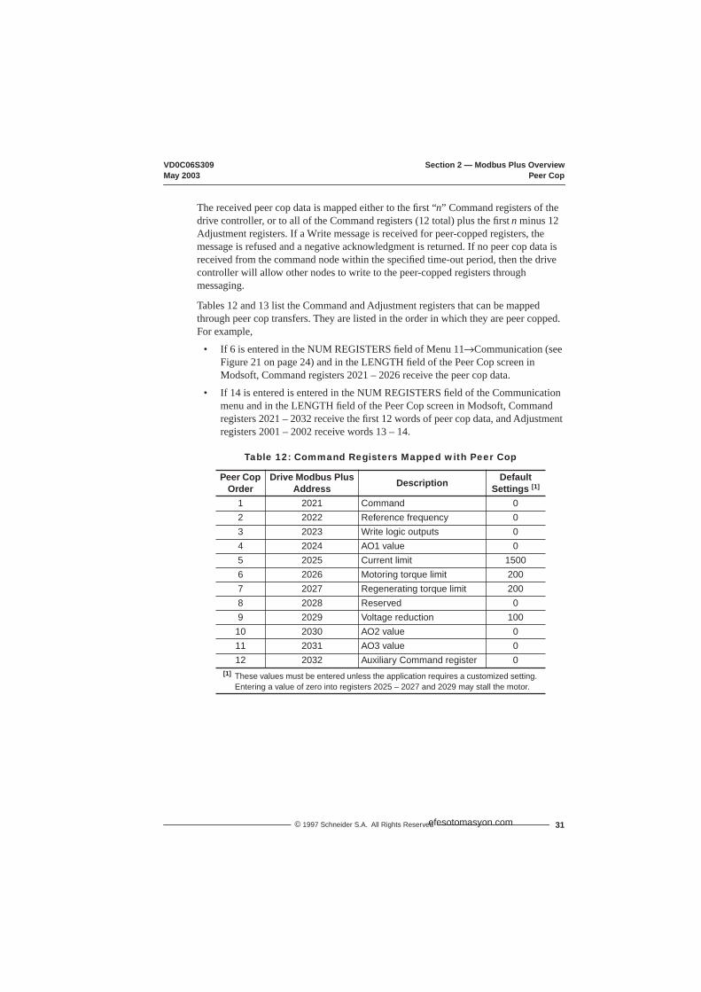
The received peer cop data is mapped either to the first “n” Command registers of the drive controller, or to all of the Command registers (12 total) plus the first n minus 12 Adjustment registers. If a Write message is received for peer-copped registers, the message is refused and a negative acknowledgment is returned. If no peer cop data is received from the command node within the specified time-out period, then the drive controller will allow other nodes to write to the peer-copped registers through messaging.
Tables 12 and 13 list the Command and Adjustment registers that can be mapped through peer cop transfers. They are listed in the order in which they are peer copped. For example,
• If 6 is entered in the NUM REGISTERS field of Menu 11→Communication (see Figure 21 on page 24) and in the LENGTH field of the Peer Cop screen in Modsoft, Command registers 2021 – 2026 receive the peer cop data.
• If 14 is entered is entered in the NUM REGISTERS field of the Communication menu and in the LENGTH field of the Peer Cop screen in Modsoft, Command registers 2021 – 2032 receive the first 12 words of peer cop data, and Adjustment registers 2001 – 2002 receive words 13 – 14.
Table 12: Command Registers Mapped with Peer Cop
Peer Cop Order
Drive Modbus Plus Address Description Default
Settings [1]
1 2021 Command 02 2022 Reference frequency 03 2023 Write logic outputs 04 2024 AO1 value 05 2025 Current limit 15006 2026 Motoring torque limit 2007 2027 Regenerating torque limit 2008 2028 Reserved 09 2029 Voltage reduction 10010 2030 AO2 value 011 2031 AO3 value 012 2032 Auxiliary Command register 0
[1] These values must be entered unless the application requires a customized setting. Entering a value of zero into registers 2025 – 2027 and 2029 may stall the motor.
efesotomasyon.com

Section 2 — Modbus Plus Overview VD0C06S309Peer Cop May 2003
© 1997 Schneider S.A. All Rights Reserved32
For more details on Adjustment and Command registers, see “Section 3 — Register Descriptions”.
Table 13: Adjustment Registers Mapped with Peer Cop [1, 2]
Peer Cop Order
Drive Modbus Plus Address Description Default
Settings [3]
13 2001 High speed 60014 2002 Low speed 015 2003 Accel 1 3016 2004 Decel 1 3017 2005 Accel 2 5018 2006 Decel 2 5019 2007 Slip compensation 3020 2008 IR compensation 10021 2009 Profile 2022 2010 Voltage boost 2023 2011 Damping 2024 2012 Bandwidth 2025 2013 Motor overload 43 [4]
26 2014 Reserved [5]27 2015 Reserved [5]28 2016 Reserved [5]29 2017 Reserved [5]30 2018 Reserved [5]31 2019 Reserved [5]32 2020 Reserved [5]
[1] Adjustments Peer-Copped to these registers are only written to the drive controller's non-volatile memory when bit 2021,15 is set to 1. The factory setting is 0, and it is recommended that you leave it at 0. If you Peer-Cop a change to an Adjustment register and want to save the change, after Peer-Copping, cycle 2021,15 (set to 1, then back to 0). Adjustments Peer-Copped to these registers since the last time the bit was cycled are lost if all power to the controller is removed. Adjustments made through messaging are automatically stored in the controller's non-volatile memory.
[2] If multi-motor operation is selected, the values in these registers affect the motor currently active. For more information on 2021,11 & 12, see Tables 18 & 20 on pages 45 & 46.
[3] You must enter these values unless your application requires a customized setting.[4] In an ATV66U41N4 drive controller, the setting of 43 is the default Motor Overload
setting. For all other size controllers, the default setting is 0.9 times the Nominal Drive Controller Output Current (see bulletin VD0C06S304_).
[5] These registers are reserved for future use. DO NOT Peer Cop to these registers.
efesotomasyon.com

VD0C06S309 Section 2 — Modbus Plus OverviewMay 2003 Global Data Transmission
33© 1997 Schneider S.A. All Rights Reserved
Global Data TransmissionWhen a networked node holds the token, it may communicate with other nodes on the link and gather network statistics. When a node releases the token, it appends up to 32 sixteen-bit words of global data to the token frame. This data packet is seen by all nodes present on the network, and any appropriately programmed node can extract the data and record it in its global database. For a Modbus Plus network with the maximum 64 nodes, the global database can be up to 2048 sixteen-bit words (32 words per node). Global data cannot be shared between networks since the token cannot pass through a bridge.
If global data transmission is enabled for the ALTIVAR 66 drive controller, up to the first 32 display registers of the drive controller can be broadcast to the network as global data with each token rotation. To enable global data transmission, enter the number of display registers to be transmitted in the ”Global Tx” field of Menu 11→Communication (see Figure 21 on page 24). Entering “0” in this field disables global data transmission.
Table 14 lists the display registers transmitted as global data, their addresses in the drive controller, and the order in which the registers are transmitted in global data transfers. For example, if “8” is entered in the “Global Tx” field of Menu 11→Communication,the first eight display registers (words 2041 – 2048) will be broadcast as global data each time the drive controller passes the token.
Table 14: Display Parameters Mapping with Global Data
OrderDrive
Modbus Plus
AddressRegister Description Order
DriveModbus
PlusAddress
Register Description
1 2041 State register 17 2057 Motor thermal state2 2042 Output frequency 18 2058 Drive thermal state3 2043 Output current 19 2059 Elapsed time (hours)4 2044 I/O values 20 2060 Elapsed time (minutes)5 2045 Value of AI1 21 2061 Motor RPM6 2046 Motor torque 22 2062 Machine speed ref. (customer units)7 2047 Reference frequency 23 2063 Machine speed (customer units)8 2048 2nd state register 24 2064 Value of AI29 2049 3rd state register 25 2065 Value of AI3
10 2050 4th state register 26 2066 Value of AI411 2051 Fault-causing trip 27 2067 Value of AO112 2052 Display of present fault 28 2068 Value of AO213 2053 Output power 29 2069 Value of AO314 2054 Output voltage 30 2070 Speed April output15 2055 Line voltage 31 2071 Reserved16 2056 DC voltage 32 2072 Motor nominal voltage
efesotomasyon.com

Section 2 — Modbus Plus Overview VD0C06S309Command Semaphore May 2003
© 1997 Schneider S.A. All Rights Reserved34
Command and Adjustment SemaphoresSince the drive controller can be commanded from many different devices (for example, the keypad or devices connected through the serial link), it provides a Command Semaphore to ensure that only one device has command rights at any given time. A device may request reservation of the Command Semaphore and if the reservation is successful, that device will be granted exclusive rights to write to the drive controller’s Command registers. Other devices may still read the Command registers, but any write attempts will be refused. The Command Semaphore can only be reserved through messaging.
Any node on the network can gain exclusive rights to the Adjustment registers by reserving the Adjustment Semaphore. The Adjustment Semaphore can only be reserved through messaging. Other devices may still Read the Adjustment registers, but all Write attempts are refused.
The Command and Adjustment Semaphores can be reserved by different nodes.
NOTE: If the Peer Cop Command node reserves the Command OR Adjustment Semaphore, this will disable its own Peer Cop capability.
Example of Modbus Plus Network OperationFigure 25 illustrates typical Modbus Plus network operation with two ATV 66 drive controller nodes. Figure 26 shows how reserving the Command Semaphore affects the same network.
Figure 25: Typical Modbus Plus Network with ATV66 Drive Controller Nodes
Modbus PlusNetwork 2
Modbus PlusNetwork 1
Node 2Node 4
Drive 1 Drive 2
BridgeNode 3
Modicon PLCNode 1 MMI
Node 2
Drive 2
Drive 1Speed = xx
Current = xx
Speed = xx
Modicon PLCNode 3
Node 6 onModbus Plus
Network 1Global Data
Node 4
Node 5
Node 5
Node 1
Node 1 PLC configured to send Peer Cop data to registers 2021 & 2022 in Drive 1.
Node 1 becomes the CommandNode.
Specific Transfer from Node 3 to Node 5 is ignored by Drive 2, since it has Peer Cop reception disabled.
Specific Transfer from Node 3 to Node 4 is ignored by Drive 1, since its designated Command Node is Node 1.
Node 3 can send messages to Node 5 using MSTR blocks.
MMI sends messages to Read & Write data to Drive 1 (except registers 2021 & 2022).
Nodes may communicate with drives via messaging only (except registers 2021 & 2022 in Drive 1).
Peer Cop = Yes
Command Node = 1
Num Registers = 2
Peer Cop = No
efesotomasyon.com
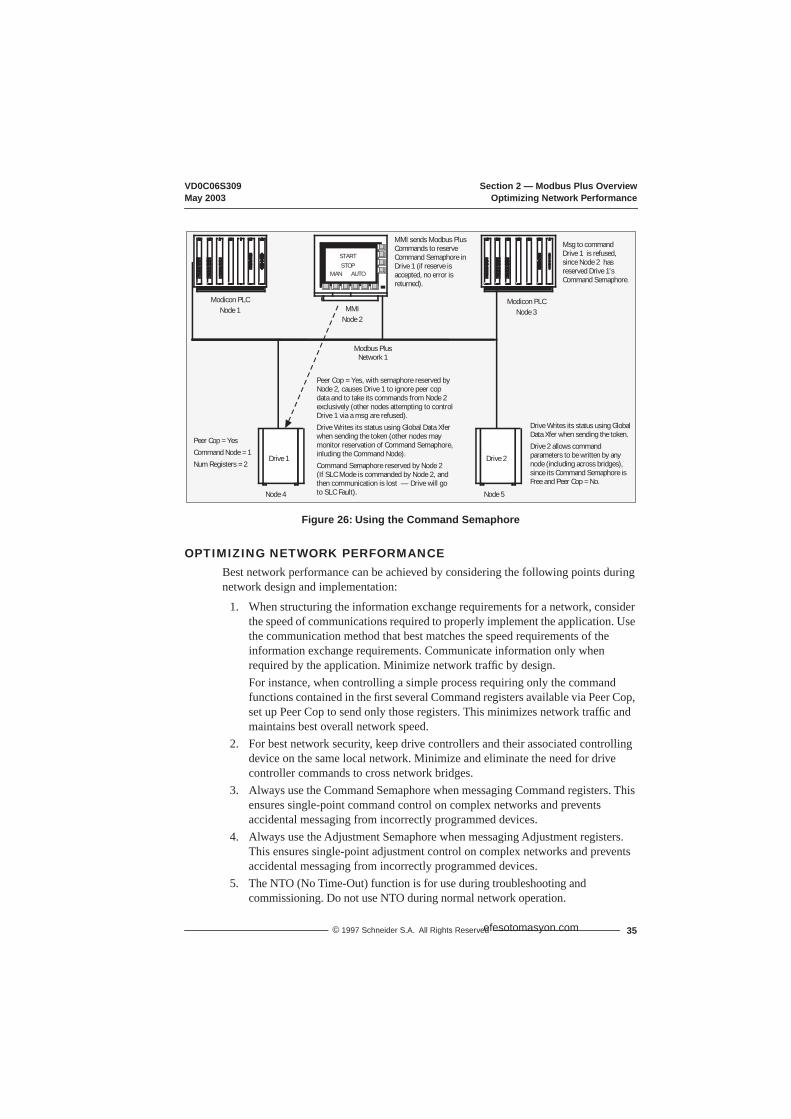
VD0C06S309 Section 2 — Modbus Plus OverviewMay 2003 Optimizing Network Performance
35© 1997 Schneider S.A. All Rights Reserved
Figure 26: Using the Command Semaphore
OPTIMIZING NETWORK PERFORMANCEBest network performance can be achieved by considering the following points during network design and implementation:
1. When structuring the information exchange requirements for a network, consider the speed of communications required to properly implement the application. Use the communication method that best matches the speed requirements of the information exchange requirements. Communicate information only when required by the application. Minimize network traffic by design.For instance, when controlling a simple process requiring only the command functions contained in the first several Command registers available via Peer Cop, set up Peer Cop to send only those registers. This minimizes network traffic and maintains best overall network speed.
2. For best network security, keep drive controllers and their associated controlling device on the same local network. Minimize and eliminate the need for drive controller commands to cross network bridges.
3. Always use the Command Semaphore when messaging Command registers. This ensures single-point command control on complex networks and prevents accidental messaging from incorrectly programmed devices.
4. Always use the Adjustment Semaphore when messaging Adjustment registers. This ensures single-point adjustment control on complex networks and prevents accidental messaging from incorrectly programmed devices.
5. The NTO (No Time-Out) function is for use during troubleshooting and commissioning. Do not use NTO during normal network operation.
Modbus PlusNetwork 1
Node 4
Modicon PLCNode 1 MMI
Node 2
STARTSTOP
MAN AUTO
Modicon PLCNode 3
Node 5
Msg to command Drive 1 is refused, since Node 2 has reserved Drive 1'sCommand Semaphore.
Drive 2Drive 1
Peer Cop = Yes
Command Node = 1
Num Registers = 2
Peer Cop = Yes, with semaphore reserved by Node 2, causes Drive 1 to ignore peer cop data and to take its commands from Node 2 exclusively (other nodes attempting to control Drive 1 via a msg are refused).
Drive Writes its status using Global Data Xfer when sending the token (other nodes may monitor reservation of Command Semaphore, inluding the Command Node).
Command Semaphore reserved by Node 2 (If SLC Mode is commanded by Node 2, and then communication is lost — Drive will go to SLC Fault).
Drive Writes its status using Global Data Xfer when sending the token.
Drive 2 allows commandparameters to be written by any node (including across bridges), since its Command Semaphore is Free and Peer Cop = No.
MMI sends Modbus Plus Commands to reserve Command Semaphore in Drive 1 (if reserve is accepted, no error is returned).
efesotomasyon.com

Section 2 — Modbus Plus Overview VD0C06S309Drive Communication Principles May 2003
© 1997 Schneider S.A. All Rights Reserved36
6. Use distributed control where possible. The ATV66 drive controller has a large number of applications functions that can be used in conjunction with network communications. Where possible, use these functions to allow local control by the drive controller while using the network for communicating supervisory information. This minimizes the information exchange burden on the network and unburdens the controlling device.
7. Understand the failure possibilities of the network designed. Provide control redundancies and contingencies appropriate for the intended application.
8. Follow the wiring practices described in Section 1. Improperly installed network wiring can cause noisy or intermittent data transmission with resulting loss of network speed and security.
DRIVE CONTROLLER COMMUNICATION PRINCIPLES
Data StructuresATV66 drive controllers are adjusted, controlled, and monitored through data stored in drive controller memory. The data consists of bits and words. Words consist of 16 bits and are designated Wx, where x indicates word number. Words are used for saving numerical values (for example, -32768 to +32767) or 16 independent logic states (bits).
For example, 2022 saves a numerical value for frequency reference and 2041 is a register consisting of 16 state bits. The notation 2041,2 designates bit 2 of register 2041.
Access to DataThe tables in Section 3 (pages 41 – 62), list drive controller parameters accessible by communication. Details of each parameter and how it affects drive controller operation are explained in bulletins VD0C06S305_ and VD0C06T306_.
Data such as fault and monitoring information can only be Read; the drive controller refuses attempts to Write to this data. You can Read from and Write to words corresponding to the drive controller adjustment, frequency reference, and command parameters.
UnitsWords are always in signed (-32768 to +32767) or unsigned (0 to 65535) units. For example, 2003 (Acceleration 1 time) is in units of 0.1 s Therefore, a value of 60 corresponds to an acceleration time of 6 s.
RangeEach parameter has an allowable range. If a value outside of the range is written, the parameter is set to the range limit or to the factory default value.
efesotomasyon.com
VD0C06S309 Section 2 — Modbus Plus OverviewMay 2003 Drive Communication Principles
37© 1997 Schneider S.A. All Rights Reserved
Values at Power UpAt each power up, the ATV 66 drive controller is initialized with the configuration and adjustments saved in its non-volatile memory. This includes values saved to drive controller Modbus Plus Adjustment registers 2001 – 2013 via the keypad, messaging, or by Peer-Copping and cycling the Peer Cop Adjustment storage bit (2021,15). Drive controller Modbus Plus Command registers 2021 – 2032 are set to their factory default values (see Table 12 on page 31). Also at power up, the drive controller is placed in Local command (Terminal Strip or Keypad).
Taking Command over the NetworkThe minimum requirements to start drive from serial link are:
• Make selections in drive controller Menu 11→Communication.• An active signal must be present on LI1 on the control basket. If you are using a
115V I/O Extension module (VW3A66202T ), LI1 of that module must also be active.
• Ensure Forced Local is not active (see page 26).• Ensure no other processor on the network has reserved the Command Semaphore
(see page 34).• Enable Serial Link Control — set word 2021,1 (DLI) & 2021,2 (FLI) to 1.
NOTE: This manual does not support split DLI/FLI Control (see Table 18 on page 44).— Status display on keypad will read “SLC”.
• Send Run Command — set word 2021,5 (Stop/Run) to 1.• Send Speed Reference — write a value between 3970 (60 Hz, forward) and -3970
(60 Hz, reverse) to word 2022.
Parameter Types
There are several different types of parameters:
• Command parameters — Enable and disable Serial Link Command mode, start and stop the drive controller, and command the general operation of the drive. Command parameters cannot be modified if:— Command Semaphore has been reserved by another device, or— In Forced Local Mode, or— Drive controller is being Peer Copped by another device.Command parameters (except 2121,1, 2 & 15) can be modified only if 2021,1 (DLI) & 2021,2 (FLI) are set, and can always be monitored by any device.
• Adjustment parameters — Used to change variables in the drive controller. These parameters can be written and read by any device while the controller is running or stopped. For exclusive control of the Adjustment registers, the device must reserve the Adjustment Semaphore.
• Display parameters (Read only)— Can be monitored by any device.
efesotomasyon.com
Section 2 — Modbus Plus Overview VD0C06S309Drive Communication Principles May 2003
© 1997 Schneider S.A. All Rights Reserved38
Protection of Command Access
The Command Semaphore ensures access protection in writing the Command registers. The device that sets 2236 to 1 reserves the semaphore and prohibits access to writing the Command registers by all other devices. The Command Semaphore is freed by setting 2236 to 0. It must be freed by the device that reserved it. The Command Semaphore is also freed if:
• There is a communication fault; or• No message is sent for 60 seconds by the device which reserved it to the device
controller.
The Command Semaphore is automatically reserved by Forced Local. In this case, the device that previously reserved the Command Semaphore loses it.
NOTE: It is possible to command the drive controller without reserving the semaphore. However, to improve network security, you should set (reserve) the semaphore when commanding the drive controller via messaging.
Protection of Adjustment AccessThe Adjustment Semaphore ensures access protection when writing to the Adjustment registers. The device that sets Register 199 to 1 reserves the Adjustment Semaphore and prevents other devices from writing to the Adjustment registers. To free the Adjustment Semaphore, set Register 199 to 0 (it must be freed by the device that reserved it). The Adjustment Semaphore is also freed if:
• There is a communication fault, or• No message is sent for 60 seconds by the device that reserved the semaphore.
Forced Local automatically reserves the Adjustment Semaphore and the device that reserved the Adjustment Semaphore loses it.
NOTE: You can adjust the drive controller without reserving the Adjustment semaphore. However, to improve network security, you should reserve (set) the Adjustment semaphore when commanding the drive controller via messaging.
Data Priority
When several types of parameters are written in the same request, they are treated in the following order:
1. Writing bits 2021,1 (DLI) & 2021,2 (FLI) to 12. Adjustment parameters3. Command parameters (except 2021,1 & 2021,2)
Access Protection by Forced Local
Writing of Command registers is blocked during Forced Local. Forced Local automatically reserves the Command and Adjustment Semaphores even if they are already reserved.
efesotomasyon.com

VD0C06S309 Section 2 — Modbus Plus OverviewMay 2003 Drive Communication Principles
39© 1997 Schneider S.A. All Rights Reserved
Command Mode Transitions
Wire the drive controller as shown in the Receiving, Installation, & Start-Up manual (VD0C06S304_). When transitioning between Serial Link command, Terminal Strip command, and Keypad command, the drive controller operates as shown in Table 15. There are two ways to transition between states:
• By a change in state of Forced Local (by logic input or keypad Function key), or• By a change in state of the DLI/FLI bits in 2021.
Table 15: Transition Between Command States
DLI/FLI 0/0 0/0 0/0 0/0 1/1 1/1 1/1 1/1
SLC Run 0 0 1 1 0 0 1 1
DLI/FLI SLC Run Forced Local 0 1 0 1 0 1 0 1
0/0 0 0 NoChange
NoChange
NotPossible
SLC(Stop)
NotPossible SLC (Run) Not
Possible
0/0 0 1 NoChange
NotPossible
NoChange
NotPossible
NoChange
NotPossible
NoChange
0/0 1 0 NoChange
NotPossible
NoChange
SLC(Stop)
NotPossible SLC (Run) Not
Possible
0/0 1 1 NotPossible
NoChange
NoChange
NotPossible
NoChange
NotPossible
NoChange
1/1 0 0 Local 2 NotPossible Local 2 Not
Possible Local 2 SLC (Run) NotPossible
1/1 0 1 NotPossible
NoChange
NotPossible
NoChange
SLC(Stop)
NotPossible
NoChange
1/1 1 0 Local 1 NotPossible Local 1 Not
PossibleSLC
(Stop)Not
Possible Local 2
1/1 1 1 NotPossible
NoChange
NotPossible
NoChange
NotPossible
NoChange
SLC(Run)[1]
[1] Local Command mode speed and direction are copied to 2022 and 2041,9 respectively.
SLC: Serial Link Command
Local 1: When transferring to Keypad command mode, the drive controller stops. When transferring to Terminal command mode, the drive controller stops unless a terminal command is present (direction and speed coming from the terminal strip).
Local 2: When transferring to Keypad command mode, there is no change in drive controller state. When transferring to Terminal command mode, drive controller stops unless a terminal command is present (direction and speed coming from the terminal strip).
UNINTENDED EQUIPMENT ACTION• This manual does not support split control of the DLI and FLI bits
(i.e., DLI = 1 and FLI = 0, or DLI = 0 and FLI = 1).• If split control of DLI and FLI is required for your application, contact your Square D
representative for assistance.• DO NOT program the controller in split control of DLI and FLI mode using only the
information in this manual!Failure to follow these instructions can result in death, serious injury, or equipment damage.
WARNING
efesotomasyon.com

Section 2 — Modbus Plus Overview VD0C06S309Drive Communication Principles May 2003
© 1997 Schneider S.A. All Rights Reserved40
Compatibility of Application Functions
Table 16 shows the compatibility of ATV66 application functions with Serial Link Command Mode (both DLI & FLI are set). See footnotes for compatibility index. You must program these applications first with the keypad.
Table 16: Compatibility of Application Functions
Function CompatibilityIndex Function Compatibility
Index+Speed / –Speed 6 Multi-Motor Selection 4Alternate Ramps by LI 4 Multi-Parameters Selection 4Alternate Ramps by Freq. Level 4 Orient 3Auto Run 6 PI Regulator 6Auto/Manual 6 Power Loss 1Automatic Restart 1 Preset Speeds 6Brake Sequence 2 Run Forward (2-wire control) 4Bypass 2 Run Permissive (LI1, 2-wire control) 2Catch on the Fly 7 Run Reverse (2-wire control) 4Controlled Stop by Freq. Level 1 Setpoint Memory 6Controlled Stop by LI. 6 Shutdown 1Controlled Stop by Freq. Level & LI 6 Skip Frequencies 1Default Current Limit 4 Speed Reference 4Current Limit by AI 4 Tachometer Feedback 6Current Limit by Freq. Level 4 Terminal / Keypad Selection 6Current Limit by LI 4 Default Torque Limit 4Customer Fault 4 Torque Limit by AI 4Cycles 6 Torque Limit by Freq. Threshold 4Factory Reset 6 Torque Limit by LI 4Forced Local 5 Default Voltage Reduction 4Fault Reset 4 Voltage Reduction by AI 4Foldback 4 Voltage Reduction by Freq. Threshold 4Jog 6 Voltage Reduction by LI 4Loss of Follower Detection 6
Compatibility Index:1.Functionality is the same whether in SLC mode or in Local
Command mode (terminal strip or keypad). Interaction with terminal strip or keypad is not necessary.
2. Functionality is the same whether in SLC mode or in Local Command mode (terminal strip or keypad). Responds to necessary terminal strip inputs and provides necessary terminal strip outputs.
3.Compatible with SLC mode, but must be activated by register or bit manipulation, not a Local Command mode input (terminal strip or keypad). Responds to necessary terminal strip inputs (except activation) and provides necessary terminal strip outputs.
4.Compatible with SLC mode, but must be activated and/or adjusted by register or bit manipulation, not a Local Command mode input. Does not interact with the terminal strip or keypad.
5.Has functionality only when SLC mode is enabled, but responds only to Local Command Mode input.
6.Not compatible while in SLC mode.
7.Compatible with SLC mode, but successful implementation requires continuous presence of run commands.
SLC = Serial Link Command
efesotomasyon.com

VD0C06S309 Section 3 — Register DescriptionsMay 2003 Introduction
41© 1997 Schneider S.A. All Rights Reserved
SECTION 3 — REGISTER DESCRIPTIONS
INTRODUCTIONThe Modbus Plus link identifies ALTIVAR® 66 (ATV66) drive controllers as a series of holding registers. The tables in this section describe ATV66 registers and their corresponding Modbus Plus addresses. Registers are shown as drive controller Modbus Plus addresses. These are the addresses you will use in the MSTR instructions. In this section, registers are grouped by function. For a list of registers in numerical order, see Appendix A on page 67.
NOTE: Bit 0 is the right-most (least-significant) bit. Bit 15 is the left-most (most-significant) bit.
UNINTENDED EQUIPMENT ACTION• This manual does not support split control of the DLI and FLI bits
(i.e., DLI = 1 and FLI = 0, or DLI = 0 and FLI = 1).• If split control of DLI and FLI is required for your application, contact your Square D
representative for assistance.• DO NOT program the controller in split control of DLI and FLI mode using only the
information in this manual!• Writing to registers that are designated as reserved may cause unintended
equipment operation.• DO NOT write data to registers unless the function to be performed is completely
understood. Consult the appropriate drive controller manual for additional details.Failure to follow these instructions can result in death, serious injury, or equipment damage.
WARNING
LOSS OF CONTROL• The designer of any control scheme must consider the potential failure modes of
control paths and, for certain critical control functions, provide a means to achieve a safe state during and after a path failure. Examples of critical control functions are Emergency Stop and Overtravel Stop. Separate or redundant control paths must be provided for critical control functions.
• System control paths may include communication links. Consideration must be given to the implications of unanticipated transmission delays or failures of the link.
Failure to observe these precautions can result in death, serious injury, or equipment damage.1
1. For additional information, refer to NEMA ICS 1.1-1984 (R-1990), “Safety Guidelines for the application, Installation, and Maintenance of Solid State Control” and to NEMA ICS7.1-1995, “Safety Standards for Construction and Guide for Selection, Installation and Operation of Adjustable-Speed Drive Systems.”
WARNING
efesotomasyon.com

Section 3 — Register Descriptions VD0C06S309Adjustment Registers (Read & Write) May 2003
42 © 1997 Schneider S.A. All Rights Reserved
ADJUSTMENT REGISTERS (Read & Write)
These parameters can be adjusted regardless of whether the drive controller is running or stopped and regardless of the DLI/FLI setting (see page 37).
NOTE: You can only use the keypad to choose Multi-Motor or Multi-Parameter operation. The Adjustment register values are linked with the Motor or Parameter set determined by 2021,11 and 2021,12 (see pages 45, – 46) in Serial Link Command Mode or by the keypad in Local Command Mode. For example, if you select 2 motor sets (Motor Select Switch menu) and registers 2021,11 = 1 and 2021,12 = 0, the values in these registers affect motor 2. If Multi-Motor or Multi-Parameter operation is selected, verify which motor or parameter set is being displayed in the Adjustment registers by reading bits 2048,10 and 2048,11 (see page 52) before changing the Adjustment registers.
NOTE: Adjustments Peer-Copped to these registers are only written to the drive controller's non-volatile memory when bit 2021,15 is set to 1. The factory setting is 0, and it is recommended that you leave it at 0. If you Peer-Cop a change to an Adjustment register and want to save the change, after Peer-Copping, cycle 2021,15 (set to 1, then back to 0). Adjustments Peer-Copped to these registers since the last time the bit was cycled are lost if all power to the controller is removed. Adjustments made through messaging are automatically stored in the controller's non-volatile memory, regardless of the setting of 2021,15.
efesotomasyon.com
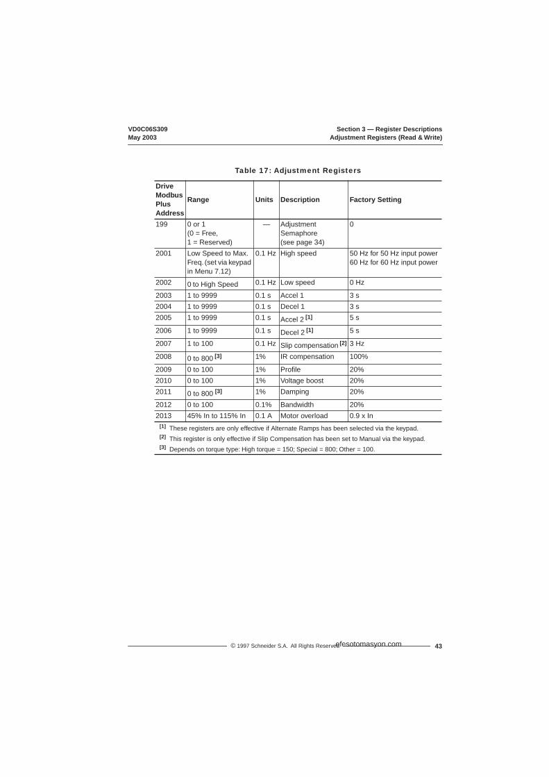
VD0C06S309 Section 3 — Register DescriptionsMay 2003 Adjustment Registers (Read & Write)
43© 1997 Schneider S.A. All Rights Reserved
Table 17: Adjustment Registers
DriveModbus PlusAddress
Range Units Description Factory Setting
199 0 or 1 (0 = Free,1 = Reserved)
— Adjustment Semaphore(see page 34)
0
2001 Low Speed to Max. Freq. (set via keypad in Menu 7.12)
0.1 Hz High speed 50 Hz for 50 Hz input power60 Hz for 60 Hz input power
2002 0 to High Speed 0.1 Hz Low speed 0 Hz
2003 1 to 9999 0.1 s Accel 1 3 s2004 1 to 9999 0.1 s Decel 1 3 s2005 1 to 9999 0.1 s Accel 2 [1] 5 s
2006 1 to 9999 0.1 s Decel 2 [1] 5 s
2007 1 to 100 0.1 Hz Slip compensation [2] 3 Hz
2008 0 to 800 [3] 1% IR compensation 100%
2009 0 to 100 1% Profile 20%2010 0 to 100 1% Voltage boost 20%2011 0 to 800 [3] 1% Damping 20%
2012 0 to 100 0.1% Bandwidth 20%2013 45% In to 115% In 0.1 A Motor overload 0.9 x In
[1] These registers are only effective if Alternate Ramps has been selected via the keypad.[2] This register is only effective if Slip Compensation has been set to Manual via the keypad.[3] Depends on torque type: High torque = 150; Special = 800; Other = 100.
efesotomasyon.com

Section 3 — Register Descriptions VD0C06S309Command Registers (Read & Write) May 2003
44 © 1997 Schneider S.A. All Rights Reserved
COMMAND REGISTERS (READ & WRITE)Command registers cannot be modified if another device on the Modbus Plus Network has reserved this drive’s Command Semaphore, or is Peer Copping the desired Command register. Command registers can also not be modified if Forced Local is active on this drive. In addition, Command registers (except bits 2021,1 [DLI], 2021,2 [FLI], and 2021,15 [Peer Cop Adjustment storage]) can only be modified if DLI and FLI are set high (Serial Link Command is enabled).
NOTE: Bit 0 is the right-most (least-significant) bit. Bit 15 is the left-most (most-significant) bit.
Table 18: Command Registers
DriveModbus Plus
AddressDescription Possible Values
2021 Drive reset 2021,0 = 02021,0 = 1
No resetReset (must be in Serial Link Command [SLC] mode for reset to take effect)
Assignment of logic commands over link (DLI) [1]
2021,1 = 02021,1 = 1
No logic commands over linkLogic commands over link
Assignment of references over link (FLI) [1]
2021,2 = 02021,2 = 1
No references over linkReferences over link
Alternate ramps (Ramp 2) 2021,3 = 02021,3 = 1
Ramp 1Ramp 2
Suppression of communication control (NTO)
2021,4 = 02021,4 = 1
Monitor communication faultDo not monitor communication fault (no time-out)
[1] Always write both bits to the same state. For operation in Serial Link Command (SLC) mode, DLI and FLI must be set to 1 and LI1 must be active.
UNINTENDED EQUIPMENT ACTION• This manual does not support split control of the DLI and FLI bits
(i.e., DLI = 1 and FLI = 0, or DLI = 0 and FLI = 1).• If split control of DLI and FLI is required for your application, contact your
Square D representative for assistance.• DO NOT program the controller in split control of DLI and FLI mode using
only the information in this manual!Failure to follow these instructions can result in death, serious injury, or equipment damage.
WARNING
LOSS OF CONTROLSetting 2021,4 (NTO) to 1 disables serial link fault protection. Provide alternate control paths when disabling the serial link fault protection.Disabling the serial link fault protection can result in loss of control and can result in death, serious injury, or equipment damage.
WARNING
efesotomasyon.com

VD0C06S309 Section 3 — Register DescriptionsMay 2003 Command Registers (Read & Write)
45© 1997 Schneider S.A. All Rights Reserved
2021 (cont’d) Run/Stop command [2, 5] 2021,5 = 02021,5 = 1
StopRun
Braking by DC injection (DCB)
2021,6 = 02021,6 = 1
No command to inject DCCommand to inject DC
Orient Stop 2021,7 = 02021,7 = 1
Orient StopNormal Stop
Freewheel stopFast stop
2021,82021,9 See Table 19 on page 46
Command of Voltage Reduction
2021,10 See Table 22 on page 47
Multi-Motors orMulti-Parameters [3] 2021,11
2021,12See Table 20 on page 46
Reserved 2021,13External fault command (EFL)
2021,14 = 02021,14 = 1
No faultFault [4]
Peer Cop Adjustment Storage
2021,15 = 02121,15 = 1
No storageStorage [6]
[2] Simultaneously writing 2021,1, 2021,2 and 2021,5 to zero while the drive controller is running in SLC mode transfers control to Local Command mode (Keypad or Terminal Strip). The drive controller responds as indicated in Table 15 on page 39. However, 2021,5 remains active.
[3] Always stop drive controller and be sure it is in the Ready (RDY) state before switching to another motor.[4] Forces drive controller to fault when in SLC mode (DLI & FLI = 1) and when LIx is configured for customer fault.[5] Keypad stop button stops drive controller, regardless of control mode (Serial, Keypad, or Terminal). To restart
drive controller, you must cycle (→Off→On) the appropriate Run command.[6] Data sent to Adjustment registers via Peer-Copping are only written to the drive controller's non-volatile memory
when bit 2021,15 is set to 1. The factory setting is 0, and it is recommended that you leave it at 0. If you Peer-Cop a change to an Adjustment register and want to save the change, after Peer-Copping, cycle 2021,15 (set to 1, then back to 0). Adjustments Peer-Copped to these registers since the last time the bit was cycled are lost if all power to the controller is removed. Adjustments made through messaging are automatically stored in the controller's non-volatile memory, regardless of the setting of 2021,15.
Table 18: Command Registers (Cont’d)
DriveModbus Plus
AddressDescription Possible Values
LOSS OF CONTROL• When using Multi-Motor function, partial transfer of motor commands may
occur if you attempt a command mode transfer with controller in running state (this includes motor operation with a zero speed reference).
• When using Multi-Motor function, always stop drive controller before switching between Terminal Command mode and Serial Link Command mode. Controller should be in Ready (RDY) state prior to changing command modes.
Failure to follow these instructions can result in death, serious injury, or equipment damage.
WARNING
efesotomasyon.com

Section 3 — Register Descriptions VD0C06S309Command Registers (Read & Write) May 2003
46 © 1997 Schneider S.A. All Rights Reserved
Table 19: Freewheel & Fast Stop Selection
Freewheel Stop2021,8
Fast Stop2021,9 Stop Type
0 0 Normal stop1 1 Freewheel stop1 0 Freewheel stop0 1 Fast stop
Table 20: Multi-Motor or Multi-Parameter Selection
Bit A2021,11
Bit B2021,12 Selection
0 0 Use Motor 1 or 1st parameter set [1]
1 0 Use Motor 2 or 2nd parameter set [1]
0 1 Use Motor 3 or 3rd parameter set [1]
1 1 Unchanged (uses existing drive parameters)[1] Function of Motor Select Switch setting (Menu 7.2→Application Functions).
Table 21: Additional Command Registers
Drive Modbus Plus Address Range Description Possible Values
2022 -32767to
32767
Reference Frequency 26478 = 400 Hz;-26478 = - 400 Hz (reverse)Factory default = 0 (0 Hz)
2032,1 0 or 1 Run Direction 0 = Forward1 = Reverse Factory default = 0
2032,8 0 or 1 Elapsed Timer Reset 0 = No Reset1 = Reset Elapsed TimerFactory default = 0
2032,bits 2, 4 – 7, 9 – 15 Reserved
2236 0 or 1 Command Semaphore (see page 34)
0 = Free1 = Reserved Factory default = 0
efesotomasyon.com
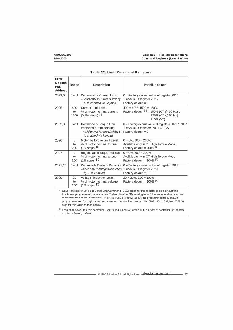
VD0C06S309 Section 3 — Register DescriptionsMay 2003 Command Registers (Read & Write)
47© 1997 Schneider S.A. All Rights Reserved
Table 22: Limit Command Registers
DriveModbus PlusAddress
Range Description Possible Values
2032,0 0 or 1 Command of Current Limit– valid only if Current Limit by
LI is enabled via keypad
0 = Factory default value of register 20251 = Value in register 2025Factory default = 0
2025 400to
1500
Current Limit Level,% of motor nominal current(0.1% steps) [1]
400 = 40%; 1500 = 150%Factory default [2] = 150% (CT @ 60 Hz) or
135% (CT @ 50 Hz)110% (VT)
2032,3 0 or 1 Command of Torque Limit (motoring & regenerating)– valid only if Torque Limit by LI
is enabled via keypad
0 = Factory default value of registers 2026 & 20271 = Value in registers 2026 & 2027Factory default = 0
2026 0to
200
Motoring Torque Limit Level,% of motor nominal torque (1% steps) [1]
0 = 0%; 200 = 200%. Available only in CT High Torque ModeFactory default = 200% [2]
2027 0to
200
Regenerating torque limit level, % of motor nominal torque(1% steps) [1]
0 = 0%; 200 = 200%Available only in CT High Torque ModeFactory default = 200% [2]
2021,10 0 or 1 Command of Voltage Reduction– valid only if Voltage Reduction
by LI is enabled
0 = Factory default value of register 20291 = Value in register 2029Factory default = 0
2029 20to
100
Voltage Reduction Level,% of motor nominal voltage(1% steps) [1]
20 = 20%, 100 = 100%Factory default = 100% [2]
[1] Drive controller must be in Serial Link Command (SLC) mode for this register to be active. If this function is programmed via keypad as “Default Limit” or “By Analog Input”, this value is always active. If programmed as “By Frequency Level”, this value is active above the programmed frequency. If programmed as “By Logic Input”, you must set the function command bit (2021,10, 2032,0 or 2032,3) high for this value to take control.
[2] Loss of all power to drive controller (Control logic inactive, green LED on front of controller Off) resets this bit to factory default.
efesotomasyon.com
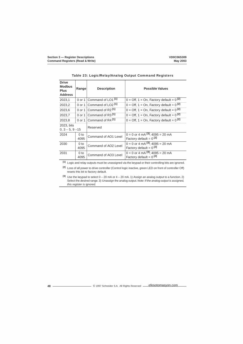
Section 3 — Register Descriptions VD0C06S309Command Registers (Read & Write) May 2003
48 © 1997 Schneider S.A. All Rights Reserved
Table 23: Logic/Relay/Analog Output Command Registers
DriveModbus PlusAddress
Range Description Possible Values
2023,1 0 or 1 Command of LO1 [1] 0 = Off, 1 = On, Factory default = 0 [2]
2023,2 0 or 1 Command of LO2 [1] 0 = Off, 1 = On, Factory default = 0 [2]
2023,6 0 or 1 Command of R2 [1] 0 = Off, 1 = On, Factory default = 0 [2]
2023,7 0 or 1 Command of R3 [1] 0 = Off, 1 = On, Factory default = 0 [2]
2023,8 0 or 1 Command of R4 [1] 0 = Off, 1 = On, Factory default = 0 [2]
2023, bits 0, 3 – 5, 9 –15 Reserved
2024 0 to 4095 Command of AO1 Level 0 = 0 or 4 mA [3]; 4095 = 20 mA
Factory default = 0 [2]
2030 0 to 4095 Command of AO2 Level 0 = 0 or 4 mA [3]; 4095 = 20 mA
Factory default = 0 [2]
2031 0 to 4095 Command of AO3 Level 0 = 0 or 4 mA [3]; 4095 = 20 mA
Factory default = 0 [2]
[1] Logic and relay outputs must be unassigned via the keypad or their controlling bits are ignored.[2] Loss of all power to drive controller (Control logic inactive, green LED on front of controller Off)
resets this bit to factory default.[3] Use the keypad to select 0 – 20 mA or 4 – 20 mA. 1) Assign an analog output to a function. 2)
Select the desired range. 3) Unassign the analog output. Note: If the analog output is assigned, this register is ignored.
efesotomasyon.com

VD0C06S309 Section 3 — Register DescriptionsMay 2003 Display Registers (Read Only)
49© 1997 Schneider S.A. All Rights Reserved
DISPLAY REGISTERS (Read Only)
Table 24: Analog Input Registers
DriveModbus Plus Address
Range Units Description Possible Values
2045 0 to 100 1% Value of Analog Input AI1
0% for 0 V and 100% for 10 V
2064 0 to 100 1% Value of Analog Input AI2
0% for 0 mA and 100% for 20 mA
2065 -100 to 100
1% Value of Analog Input AI3
-100% for -10 V and 100% for 10 V
2066 0 to 100 1% Value of Analog Input AI4
0% for 0 mA and 100% for 20 mA
21012102
Assignment of AI1Assignment of AI2
0 =1 =2 =3 =4 =5 =8 =9 =
10 =11 =
Not assignedCurrent LimitVoltage ReductionSpeed Ref. 1 (AI1 factory setting)Speed Ref. 2 (AI2 factory setting)Speed Ref. 3Setpoint Input (PI)Feedback Input (PI)Setpoint Manual Input (PI)Torque Limit
2103 Assignment of AI3 0 =1 =2 =3 =4 =5 =6 =8 =9 =
10 =11 =
Not assignedCurrent LimitVoltage ReductionSpeed Ref. 1Speed Ref. 2Speed Ref. 3 (factory setting)Tach FeedbackSetpoint Input (PI)Feedback Input (PI)Setpoint Manual Input (PI)Torque Limit
2104 Assignment of AI4 0 =1 =2 =3 =4 =5 =8 =9 =
10 =11 =
Not assigned (factory setting)Current LimitVoltage ReductionSpeed Ref. 1Speed Ref. 2Speed Ref. 3Setpoint Input (PI)Feedback Input (PI)Setpoint Manual Input (PI)Torque Limit
efesotomasyon.com

Section 3 — Register Descriptions VD0C06S309Display Registers (Read Only) May 2003
50 © 1997 Schneider S.A. All Rights Reserved
Table 25: Power, Voltage, & Thermal State Registers
Drive Modbus Plus Address Range Units Description Possible Values
2053 0.1 kW Output Power Function of hp2054 0 to Nominal
Motor Voltage1 V Output Voltage Function of drive voltage
range2055 0 to Max. [1] 1 V Line Voltage Function of drive voltage
range2056 0 to Max. [2] 1 V Bus Voltage Function of drive voltage
range2072 0 to 2 Nominal Motor Voltage
range0 = 208 – 240 V1 = 380 – 415 V2 = 440 – 460 V
2203 0 to 2 Drive Controller Voltage range
0 = Not used1 = 208 – 240 V2 = 380 – 460 V
2057 0 to 199 1% Motor Thermal State value2058 0 to 125 1% Drive controller
Thermal State valuefor D16 to C31N4 & D12 to D46M2 drives
[1] Maximum depends on line: 264 V for ATV66•••M2; 460 V for 50 Hz line (ATV66•••N4); 529 V for 60 Hz line (ATV66•••N4).
[2] Maximum depends on line: 374 V for ATV66•••M2; 651 V for 50 Hz line (ATV66•••N4); 748 V for 60 Hz line (ATV66•••N4).
Table 26: Frequency, Current, Torque, & Speed Registers
Drive Modbus Plus Address Range Unit Description Possible Values
2204 Line Frequency Recognized
0 = Unknown1 = 50 Hz2 = 60 Hz
2205 90, 200, or 400 Hz Drive Controller Max. Rated Frequency
U41 – D79 (CT) = 400 HzC10 – C31 (CT) = 200 HzVT = 90 Hz
2206 0.1 A Drive Controller Nominal Current
Function of hp, line voltage, and torque type
2207 0.1 A Drive Controller Maximum Current
Function of hp, line voltage, and torque type
2042 -26478 to 26478 Output Frequency 26478 = 400 Hz2043 0.1 A Output Current Function of hp and line
voltage2046 0 to 200 1% Motor Torque Measured % of nominal
motor torque2047 -32767 to 32767 Speed Reference 26478 = 400 Hz
-26478 = -400 Hz (reverse)2070 -400 to 400 Hz Speed Ramp
OutputSpeed command to gating control
efesotomasyon.com
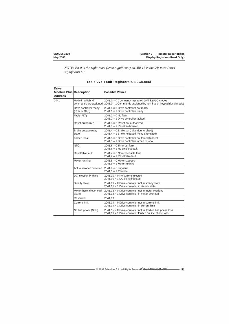
VD0C06S309 Section 3 — Register DescriptionsMay 2003 Display Registers (Read Only)
51© 1997 Schneider S.A. All Rights Reserved
NOTE: Bit 0 is the right-most (least-significant) bit. Bit 15 is the left-most (most-significant) bit.
Table 27: Fault Registers & SLC/Local
DriveModbus PlusAddress
Description Possible Values
2041 Mode in which all commands are assigned
2041,0 = 0 Commands assigned by link (SLC mode)2041,0 = 1 Commands assigned by terminal or keypad (local mode)
Drive controller ready (RDY or SLC)
2041,1 = 0 Drive controller not ready2041,1 = 1 Drive controller ready
Fault (FLT) 2041,2 = 0 No fault2041,2 = 1 Drive controller faulted
Reset authorized 2041,3 = 0 Reset not authorized2041,3 = 1 Reset authorized
Brake engage relay state
2041,4 = 0 Brake set (relay deenergized)2041,4 = 1 Brake released (relay energized)
Forced local 2041,5 = 0 Drive controller not forced to local2041,5 = 1 Drive controller forced to local
NTO 2041,6 = 0 Time-out fault2041,6 = 1 No time-out fault
Resettable fault 2041,7 = 0 Non-resettable fault2041,7 = 1 Resettable fault
Motor running 2041,8 = 0 Motor stopped2041,8 = 1 Motor running
Actual rotation direction 2041,9 = 0 Forward2041,9 = 1 Reverse
DC injection braking 2041,10 = 0 No current injected2041,10 = 1 DC being injected
Steady state 2041,11 = 0 Drive controller not in steady state2041,11 = 1 Drive controller in steady state
Motor thermal overload alarm
2041,12 = 0 Drive controller not in motor overload2041,12 = 1 Drive controller in motor overload
Reserved 2041,13Current limit 2041,14 = 0 Drive controller not in current limit
2041,14 = 1 Drive controller in current limitNo line power (NLP) 2041,15 = 0 Drive controller not faulted on line phase loss
2041,15 = 1 Drive controller faulted on line phase loss
efesotomasyon.com

Section 3 — Register Descriptions VD0C06S309Display Registers (Read Only) May 2003
52 © 1997 Schneider S.A. All Rights Reserved
Table 28: Drive Controller Status Registers
DriveModbus Plus Address
Description Possible Values
2048 Local command mode T/K
2048,0 = 02048,0 = 1
Terminal commandKeypad command
Logic commands over link (DLI)
2048,1 = 02048,1 = 1
Not activatedActivated
Reference commands over link (FLI)
2048,2 = 02048,2 = 1
Not activatedActivated
Dynamic braking 2048,3 = 02048,3 = 1
Dynamic braking not activeDynamic braking in progress
Fast stop 2048,4 = 02048,4 = 1
Fast stop not activeFast stop in progress
Power loss, ramp stop 2048,5 = 02048,5 = 1
Not activeRamp stop in progress
Gating state 2048,6 = 02048,6 = 1
Drive controller gatingDrive controller not gating
Orient complete 2048,7 = 02048,7 = 1
Orient stop not activeOrient stop complete (200 ms pulse)
Deceleration (DEC) 2048,8 = 02048,8 = 1
Drive controller not in decelerationDrive controller in deceleration
Acceleration (ACC) 2048,9 = 02048,9 = 1
Drive controller not in accelerationDrive controller in acceleration
Multi-Motor or Multi-Parameter
2048,102048,11 See Table 29 below
Reserved 2048,12Drive controller thermal fault
2048,13 = 02048,13 = 1
Drive controller not in thermal overload faultDrive controller in thermal overload fault
Torque limit 2048,14 = 02048,14 = 1
Drive controller not in torque limitDrive controller in torque limit
Stopping by the keypad 2048,15 = 02048,15 = 1
Not activeDrive controller stopped by keypad [1]
[1] Keypad Stop button stops drive controller, regardless of control mode (Serial, Keypad, Terminal). To restart the controller, you must cycle (→Off →On) the appropriate Run command. You can monitor bit 2048,15 to lock out the controller when the keypad Stop button is pressed.
Table 29: Multi-Motor or Multi-Parameter Set Selected
Bit A2048,10
Bit B2048,11 Selection
0 0 Motor 1 or 1st parameter set selected [1]
1 0 Motor 2 or 2nd parameter set selected [1]
0 1 Motor 3 or 3rd parameter set selected [1]
1 1 Unchanged[1] Function of Motor Select Switch setting (Menu 7.2→Application Functions).
efesotomasyon.com

VD0C06S309 Section 3 — Register DescriptionsMay 2003 Display Registers (Read Only)
53© 1997 Schneider S.A. All Rights Reserved
Table 30: Additional Drive Controller Status Registers
DriveModbus Plus Address
Description Possible Values
2049 Jog 2049,0 = 02049,0 = 1
Jog not in progressJog in progress
Shutdown complete 2049,1 = 02049,1 = 1
Shutdown not completeShutdown complete
Cycle complete 2049,2 = 02049,2 = 1
Cycle not completeCycle complete (200 ms pulse)
Alternate ramp 2049,3 = 02049,3 = 1
Ramp 1Ramp 2
Auto/Manual 2049,4 = 02049,4 = 1
Manual activatedAuto activated
Frequency level 1 attained 2049,5 = 02049,5 = 1
Freq. level 1 not attainedFreq. level 1 attained
Frequency level 2 attained 2049,6 = 02049,6 = 1
Freq. level 2 not attainedFreq. level 2 attained
Current level 1 attained 2049,7 = 02049,7 = 1
Current level 1 not attainedCurrent level 1 attained
Current level 2 attained 2049,8 = 02049,8 = 1
Current level 2 not attainedCurrent level 2 attained
Thermal level 1 attained 2049,9 = 02049,9 = 1
Thermal level 1 not attainedThermal level 1 attained
Thermal level 2 attained 2049,10 = 02049,10 = 1
Thermal level 2 not attainedThermal level 2 attained
No ramp follow 2049,11 = 02049,11 = 1
Not activeActive
Run output command (bypass)
2049,12 = 02049,12 = 1
Not activeActive
Rotation direction 2049,13 = 02049,13 = 1
Running in forwardRunning in reverse
Reserved 2049,142049,15
2050,0 Drive Faulted, stopped 2050,0 = 02050,0 = 1
Drive not faultedDrive faulted
2050,4 State of Adjustment Semaphore
2050,4 = 02050,4 = 1
Adjustment Semaphore freeAdjustment Semaphore reserved
2050,5 State of Command Semaphore
2050,5 = 02050,5 = 1
Command Semaphore freeCommand Semaphore reserved
2050,bits 1 – 3, 6 – 15
Reserved
efesotomasyon.com

Section 3 — Register Descriptions VD0C06S309Display Registers (Read Only) May 2003
54 © 1997 Schneider S.A. All Rights Reserved
Table 31: Motor/Parameter Set, Cycle, Preset Speed
Drive Modbus Plus Address Range Description
2075 0 to 2 Number of motor or parameter set selected:0 = Motor/Parameter set #11 = Motor/Parameter set #22 = Motor/Parameter set #3
2076 1 to 8 Cycles step number in progress2077 0 to 7 Preset speed number in progress
Table 32: Drive Controller Horsepower
Drive Modbus Plus Address Range Description Remarks
2201 0 to 22 Drive controller horsepower(hardware rating)
0 =1 =2 =3 =4 =5 =6 =7 =8 =9 =
10 =11 =12 =13 =14 =15 =16 =17 =18 =19 =20 =21 =22 =
Not usedReservedReserved2.2 kW, 3 hp3 kW4 kW, 5 hp5.5 kW, 7.5 hp7.5 kW, 10 hp11 kW, 15 hp15 kW, 20 hpReserved22 kW, 30 hp30 kW, 40 hp37 kW, 50 hp45 kW, 60 hp55 kW, 75 hp75 kW, 100hp90 kW, 125 hp110 kW, 150 hp132 kW, 200 hp160 kW, 250 hp200 kW, 300 hp220 kW, 350 hp
2202 0 to 23 Drive controller horsepower(configured rating)
Same as above with:1 =2 =
10 =23 =
0.75 kW, 1 hp1.5 kW, 2 hp18.5 kW, 25 hp250 kW, 400 hp
efesotomasyon.com

VD0C06S309 Section 3 — Register DescriptionsMay 2003 Display Registers (Read Only)
55© 1997 Schneider S.A. All Rights Reserved
Table 33: Status of Options (cards, modules, keypad)
DriveModbus Plus Address
Range Description Possible Values
2212 0 to 1 Memory card option
0 =1 =
Memory card not installedMemory card installed
2213 0 to 1 Communication carrier option
0 =1 =
Communication carrier module not installedCommunication carrier module installed
2214 0 to 1 Presence of keypad
0 =1 =
Keypad not presentKeypad installed
2215 0 to 2 I/O Extension option module
0 =1 =2 =
I/O Extension module not installed24 V I/O Extension installed115 V I/O Extension installed
2217 0, 1, 4 PCMCIA communication card
0 =1 =4 =
No PCMCIA card installedUni-Telway/Modbus/Jbus PCMCIA card installedModbus Plus PCMCIA card installed
Table 34: Command Node Status
Drive Modbus Plus Address Description Possible Values
2222 State of command node
0 =1 =2 =
DisabledOKTime-out
Table 35: Token & Message Status
Drive Modbus Plus Address Range Units Description
2223 0 to 65535
ms Token rotation time
2224 0 to 65535
Token count
2225 0 to 65535
Messages received
Table 36: Elapsed Time, Output Speed, & Machine Frequency
Drive Modbus Plus Address Units Description Possible Values
2059 H Elapsed time (hours) Total time 2059 + 20602060 min Elapsed time (minutes)2061 RPM Output speed Scale factor determined by
nominal motor RPM2062 User
definedMachine frequency reference (customer units)
Frequency times scaling factor
2063 Userdefined
Machine frequency (customer units)
Frequency times scaling factor
efesotomasyon.com

Section 3 — Register Descriptions VD0C06S309Display Registers (Read Only) May 2003
56 © 1997 Schneider S.A. All Rights Reserved
Table 37: Analog Output Assignment and Value
DriveModbus Plus Address
Range Description Possible Values
2067 0 to 100% Value of AO12068 0 to 100% Value of AO22069 0 to 100% Value of AO32105 0 to 11 Assignment of
analog output AO10 =1 =2 =3 =4 =5 =6 =7 =8 =9 =
10 =11 =
Not assignedOutput CurrentOutput Frequency (factory setting)Output PowerMotor TorqueOutput VoltageMotor Thermal StateRamp OutputPI reference OutputPI feedback OutputPI error OutputPI Integrator
2106 0 to 11 Assignment of analog output AO2
0 =1 =2 =3 =4 =5 =6 =7 =8 =9 =
10 =11 =
Not assignedMotor Current (factory setting)Motor FrequencyOutput PowerMotor TorqueOutput VoltageMotor Thermal StateRamp OutputPI Reference OutputPI Feedback OutputPI Error OutputPI Integrator
2107 0 to 11 Assignment of analog output AO3
0 =1 =2 =3 =4 =5 =6 =7 =8 =9 =
10 =11 =
Not assignedMotor CurrentMotor FrequencyOutput Power (factory setting)Motor TorqueOutput VoltageMotor Thermal StateRamp OutputPI Reference OutputPI Feedback OutputPI Error OutputPI Integrator
efesotomasyon.com

VD0C06S309 Section 3 — Register DescriptionsMay 2003 Display Registers (Read Only)
57© 1997 Schneider S.A. All Rights Reserved
Table 38: LIx/LOx/ROx State
Drive Modbus Plus Address Description Possible Values
2044 Display of LI1 activation 2044,1 = 0 Input not active2044,1 = 1 Input active
Display of LI2 activation 2044,2 = 0 Input not active2044,2 = 1 Input active
Display of LI3 activation 2044,3 = 0 Input not active2044,3 = 1 Input active
Display of LI4 activation 2044,4 = 0 Input not active2044,4 = 1 Input active
Display of LI5 activation 2044,5 = 0 Input not active2044,5 = 1 Input active
Display of LI6 activation 2044,6 = 0 Input not active2044,6 = 1 Input active
Display of LI7 activation 2044,7 = 0 Input not active2044,7 = 1 Input active
Display of LI8 activation 2044,8 = 0 Input not active2044,8 = 1 Input active
Display of LO1 activation 2044,9 = 0 Output not active2044,9 = 1 Output active
Display of LO2 activation 2044,10 = 0 Output not active2044,10 = 1 Output active
Display of R1 activation 2044,11 = 0 Output not active2044,11 = 1 Output active
Display of R2 activation 2044,12 = 0 Output not active2044,12 = 1 Output active
Display of R3 activation 2044,13 = 0 Output not active2044,13 = 1 Output active
Display of R4 activation 2044,14 = 0 Output not active2044,14 = 1 Output active
Reserved 2044,02044,15
efesotomasyon.com
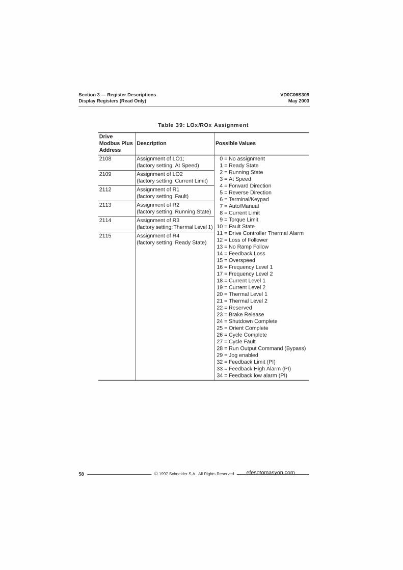
Section 3 — Register Descriptions VD0C06S309Display Registers (Read Only) May 2003
58 © 1997 Schneider S.A. All Rights Reserved
Table 39: LOx/ROx Assignment
DriveModbus Plus Address
Description Possible Values
2108 Assignment of LO1;(factory setting: At Speed)
0 =1 =2 =3 =4 =5 =6 =7 =8 =9 =
10 =11 =12 =13 =14 =15 =16 =17 =18 =19 =20 =21 =22 =23 =24 =25 =26 =27 =28 =29 =32 =33 =34 =
No assignmentReady StateRunning StateAt SpeedForward DirectionReverse DirectionTerminal/KeypadAuto/ManualCurrent LimitTorque LimitFault StateDrive Controller Thermal AlarmLoss of FollowerNo Ramp FollowFeedback LossOverspeedFrequency Level 1Frequency Level 2 Current Level 1Current Level 2Thermal Level 1Thermal Level 2ReservedBrake ReleaseShutdown CompleteOrient CompleteCycle CompleteCycle FaultRun Output Command (Bypass)Jog enabledFeedback Limit (PI)Feedback High Alarm (PI)Feedback low alarm (PI)
2109 Assignment of LO2(factory setting: Current Limit)
2112 Assignment of R1(factory setting: Fault)
2113 Assignment of R2(factory setting: Running State)
2114 Assignment of R3(factory setting: Thermal Level 1)
2115 Assignment of R4(factory setting: Ready State)
efesotomasyon.com

VD0C06S309 Section 3 — Register DescriptionsMay 2003 Display Registers (Read Only)
59© 1997 Schneider S.A. All Rights Reserved
Table 40: Logic Input Assignments
DriveModbus Plus Address
Description Possible Values
2116 Assignment of LI1: Stop (3-wire control) or Run Enable (2-wire control)(not reconfigurable)
0 =1 =2 =3 =4 =5 =6 =7 =8 =9 =
10 =11 =12 =13 =14 =15 =16 =17 =18 =19 =20 =21 =22 =23 =24 =25 =26 =27 =28 =29 =30 =31 =33 =34 =
Not assignedStop (3-wire control)Run Enable (2-wire control)ForwardReverseCurrent LimitVoltage ReductionAlternate RampsJog+Speed-SpeedControlled stopStart Cycle (Cycles)Reset Cycle (Cycles)Step Locking (Cycles)Next step (Cycles)Setpoint MemoryPreset Speed a (PS A)Preset Speed b (PS B)Preset Speed c (PS C)Orient CommandOrient PulsesForced LocalAuto/ManualTerminal/KeypadProcess Input (Bypass)Sequence Input (Bypass)Motor Select aMotor Select bCustomer FaultReset FaultAuto RunAuto/Manual (PI)Reverse Speed (PI)
2117 Assignment of LI2: Forward(not reconfigurable)
2118 Assignment of LI3(factory setting: Reverse)
2119 Assignment of LI4(factory setting: Jog)
2120 Assignment of LI5(factory setting: PS A)
2121 Assignment of LI6(factory setting: PS B)
2122 Assignment of LI7(factory setting: PS C)
2123 Assignment of LI8(factory setting: Reset Fault)
efesotomasyon.com
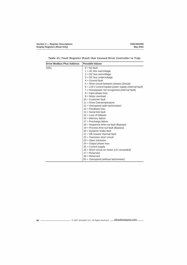
Section 3 — Register Descriptions VD0C06S309Display Registers (Read Only) May 2003
60 © 1997 Schneider S.A. All Rights Reserved
Table 41: Fault Register (Fault that Caused Drive Controller to Trip)
Drive Modbus Plus Address Possible Values2051 0 =
1 =2 =3 =4 =5 =6 =7 =8 =9 =
10 =11 =12 =13 =14 =15 =16 =17 =18 =19 =20 =21 =22 =23 =24 =25 =26 =27 =28 =29 =
No faultAC line overvoltageDC bus overvoltageDC bus undervoltageGround faultShort circuit between phases (Desat)±15 V control basket power supply (internal fault)Horsepower not recognized (internal fault)Input phase lossMotor overloadCustomer faultDrive OvertemperatureOverspeed (with tachometer)Feedback lossSerial link faultLoss of followerMemory failurePrecharge failureSequence time-out fault (Bypass)Process time-out fault (Bypass)Dynamic brake faultDB resistor thermal fault Transistor short circuitOpen transistorOutput phase lossControl supplyShort circuit on motor (LIC exceeded)ReservedReservedOverspeed (without tachometer)
efesotomasyon.com
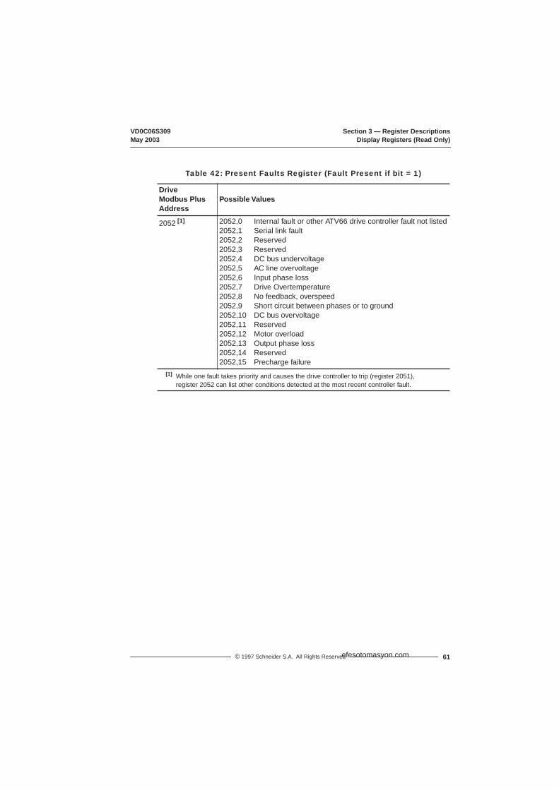
VD0C06S309 Section 3 — Register DescriptionsMay 2003 Display Registers (Read Only)
61© 1997 Schneider S.A. All Rights Reserved
Table 42: Present Faults Register (Fault Present if bit = 1)
DriveModbus Plus Address
Possible Values
2052 [1] 2052,02052,12052,22052,32052,42052,52052,62052,72052,82052,92052,102052,112052,122052,132052,142052,15
Internal fault or other ATV66 drive controller fault not listedSerial link faultReservedReservedDC bus undervoltageAC line overvoltageInput phase lossDrive OvertemperatureNo feedback, overspeedShort circuit between phases or to groundDC bus overvoltageReservedMotor overloadOutput phase lossReservedPrecharge failure
[1] While one fault takes priority and causes the drive controller to trip (register 2051), register 2052 can list other conditions detected at the most recent controller fault.
efesotomasyon.com
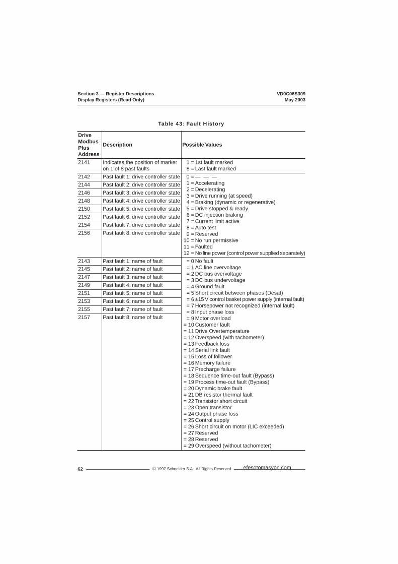
Section 3 — Register Descriptions VD0C06S309Display Registers (Read Only) May 2003
62 © 1997 Schneider S.A. All Rights Reserved
Table 43: Fault History
DriveModbus PlusAddress
Description Possible Values
2141 Indicates the position of marker on 1 of 8 past faults
1 =8 =
1st fault markedLast fault marked
2142 Past fault 1: drive controller state 0 =1 =2 =3 =4 =5 =6 =7 =8 =9 =
10 =11 =12 =
— — —AcceleratingDeceleratingDrive running (at speed)Braking (dynamic or regenerative)Drive stopped & readyDC injection brakingCurrent limit activeAuto testReservedNo run permissiveFaultedNo line power (control power supplied separately)
2144 Past fault 2: drive controller state2146 Past fault 3: drive controller state2148 Past fault 4: drive controller state2150 Past fault 5: drive controller state2152 Past fault 6: drive controller state2154 Past fault 7: drive controller state2156 Past fault 8: drive controller state
2143 Past fault 1: name of fault = 0= 1= 2= 3= 4= 5= 6= 7= 8= 9
= 10= 11= 12= 13= 14= 15= 16= 17= 18= 19= 20= 21= 22= 23= 24= 25= 26= 27= 28= 29
No faultAC line overvoltageDC bus overvoltageDC bus undervoltageGround faultShort circuit between phases (Desat)±15 V control basket power supply (internal fault)Horsepower not recognized (internal fault)Input phase lossMotor overloadCustomer faultDrive OvertemperatureOverspeed (with tachometer)Feedback lossSerial link faultLoss of followerMemory failurePrecharge failureSequence time-out fault (Bypass)Process time-out fault (Bypass)Dynamic brake faultDB resistor thermal faultTransistor short circuitOpen transistorOutput phase lossControl supplyShort circuit on motor (LIC exceeded)ReservedReservedOverspeed (without tachometer)
2145 Past fault 2: name of fault2147 Past fault 3: name of fault2149 Past fault 4: name of fault2151 Past fault 5: name of fault2153 Past fault 6: name of fault2155 Past fault 7: name of fault2157 Past fault 8: name of fault
efesotomasyon.com

VD0C06S309 Section 4 — Fault Management & Network SecurityMay 2003 Introduction
63© 1997 Schneider S.A. All Rights Reserved
SECTION 4 — FAULT MANAGEMENT & NETWORK SECURITY
A serial link fault (SLF) may occur under certain conditions. Tables 44 & 45 on page 64 list some typical conditions and the drive controller’s response. The controller’s response is based on:
• Which node put the drive controller in SLC mode (serial link command mode; DLI & FLI set to 1).
• Whether drive controller is in SLC mode.• State of bit 4 of register 2021 (NTO). If 2021,4 is set to 1, the Modbus Plus
PCMCIA card does not monitor the frequency of messaging on the serial link. It is useful to set 2021,4 to 1 during certain diagnostic and commissioning procedures. Set it to 0 for normal SLC mode operation.
LOSS OF CONTROLSetting 2021,4 (NTO) to 1 disables serial link fault protection. Provide alternate control paths when disabling the serial link fault protection.Disabling the serial link fault protection can result in loss of control and can result in death, serious injury, or equipment damage.
WARNING
efesotomasyon.com
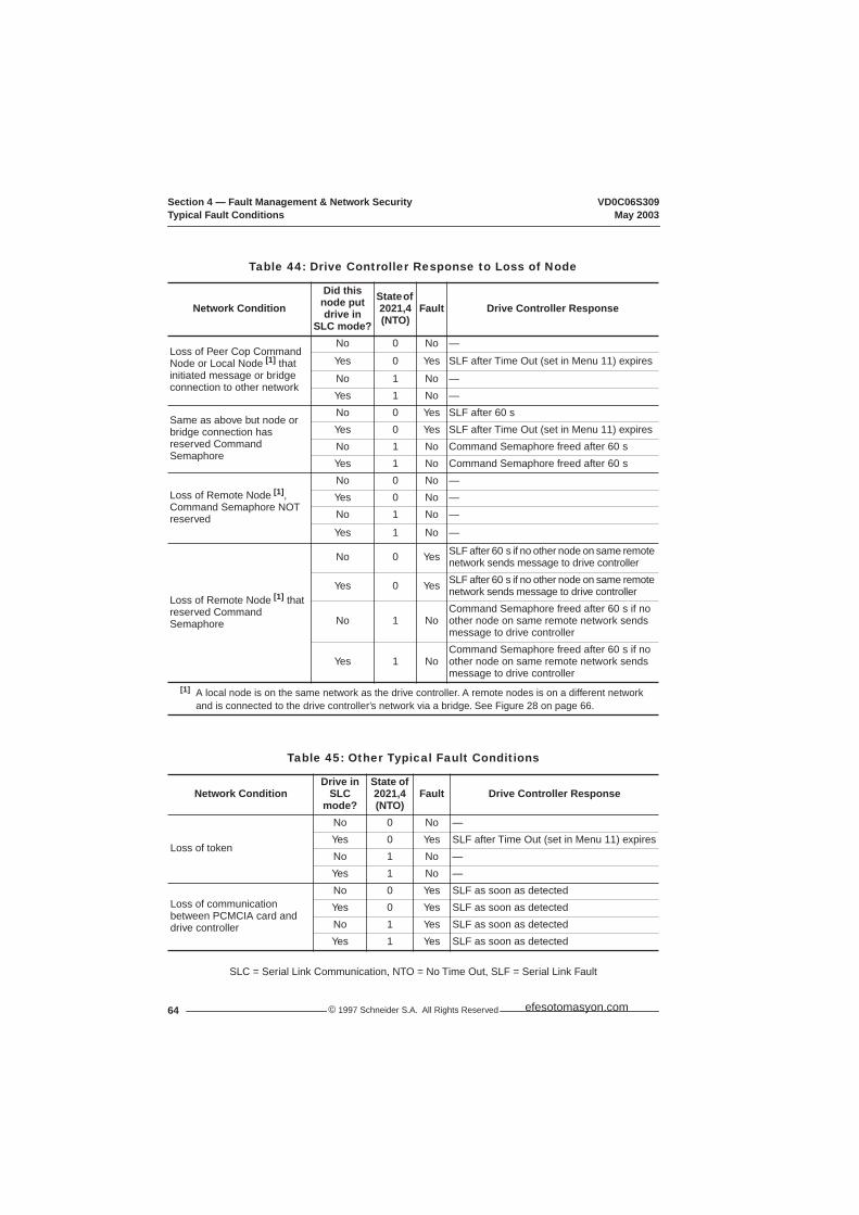
Section 4 — Fault Management & Network Security VD0C06S309Typical Fault Conditions May 2003
© 1997 Schneider S.A. All Rights Reserved64
SLC = Serial Link Communication, NTO = No Time Out, SLF = Serial Link Fault
Table 44: Drive Controller Response to Loss of Node
Network ConditionDid this node put drive in
SLC mode?
State of 2021,4(NTO)
Fault Drive Controller Response
Loss of Peer Cop Command Node or Local Node [1] that initiated message or bridge connection to other network
No 0 No —
Yes 0 Yes SLF after Time Out (set in Menu 11) expires
No 1 No —Yes 1 No —
Same as above but node or bridge connection has reserved Command Semaphore
No 0 Yes SLF after 60 sYes 0 Yes SLF after Time Out (set in Menu 11) expiresNo 1 No Command Semaphore freed after 60 sYes 1 No Command Semaphore freed after 60 s
Loss of Remote Node [1],Command Semaphore NOT reserved
No 0 No —Yes 0 No —No 1 No —
Yes 1 No —
Loss of Remote Node [1] that reserved Command Semaphore
No 0 Yes SLF after 60 s if no other node on same remote network sends message to drive controller
Yes 0 Yes SLF after 60 s if no other node on same remote network sends message to drive controller
No 1 NoCommand Semaphore freed after 60 s if no other node on same remote network sends message to drive controller
Yes 1 NoCommand Semaphore freed after 60 s if no other node on same remote network sends message to drive controller
[1] A local node is on the same network as the drive controller. A remote nodes is on a different network and is connected to the drive controller’s network via a bridge. See Figure 28 on page 66.
Table 45: Other Typical Fault Conditions
Network ConditionDrive in
SLCmode?
State of 2021,4(NTO)
Fault Drive Controller Response
Loss of token
No 0 No —Yes 0 Yes SLF after Time Out (set in Menu 11) expiresNo 1 No —Yes 1 No —
Loss of communication between PCMCIA card and drive controller
No 0 Yes SLF as soon as detectedYes 0 Yes SLF as soon as detectedNo 1 Yes SLF as soon as detectedYes 1 Yes SLF as soon as detected
efesotomasyon.com

VD0C06S309 Section 4 — Fault Management & Network SecurityMay 2003 Typical Fault Conditions
65© 1997 Schneider S.A. All Rights Reserved
Figure 27 illustrates the basic network security features of a local network with two PLCs (Programmable Logic Controllers), one MMI (Man-Machine Interface) and two drive controllers in SLC (Serial Link Command) mode.
Figure 27: Typical Communication Fault, Example 1
Modbus Plus Network
Modicon PLCNode 1
Modicon PLCNode 3
Peer Cop = NoNTO = 0
Peer Cop = YesCommand Node = 1NTO = 0
Node 4
Drive 1 Drive 2
MMINode 2
Drive 2
Drive 1Speed = xx
Current = xx
Speed = xx
Node 5
If Drive 1 loses network connection while in SLC mode, it will go to an SLC Fault within the specified MBP Time-out value.
Node 2 communicates with drive controllers via messages. If Node 2 is lost, there is no effect on drives unless it put the drive controller into SLC mode or reserved the Command Semaphore.
Other nodes may monitor Drive 1 and Drive 2 via Global Database (if fault occurs, or if global data is not received, other nodes can sense this and take corrective action).
If Node 1 (Peer CopCommand node) has put Node 4 in SLC mode and then is lost, Node 4 reports a serial link fault after time-out value (set in Menu 11) expires.
If Drive 2 loses network connection while in SLC mode, it will go to an SLC Fault within the specified MBP Time-out value, unless NTO=1.
efesotomasyon.com

Section 4 — Fault Management & Network Security VD0C06S309Typical Fault Conditions May 2003
© 1997 Schneider S.A. All Rights Reserved66
Figure 28 shows a local network with one PLC, one MMI, two drive controllers, and a remote network (Network 2) with a PLC and an MMI. A bridge separates the two networks.
Figure 28: Communication Loss, Example 2 (no SLC Fault)
The loss of a single node on the Modbus Plus network does not cause a fault, because the token can still rotate among the remaining nodes on the network. However, if a node commands the drive controller to enter serial link command mode and then loses communication with the controller, a serial link fault is issued.
To prevent loss of a commanding node without issuing a drive controller fault, command the controller from a local node. When controlling the drive controller via messaging, you should reserve the Command Semaphore. If a local node reserves the Command Semaphore and puts the controller into serial link mode (DLI & FLI = 1), it must send a message before the controller’s Time-Out period (set in menu 11) expires or the controller will stop and issue a serial link fault. If a node reserves the Command Semaphore of a controller already in serial link mode and a message is not sent to the controller within 60 seconds, the drive controller will stop and issue a serial link fault.
To ensure exclusive access rights, you should also reserve the Adjustment Semaphore when adjusting the drive controller via messaging. The node that reserves the Adjustment Semaphore has exclusive control of the Adjustment registers. The node that reserves the Adjustment semaphore must send a message to the controller within 60 seconds or the Adjustment Semaphore is freed.
Modbus PlusNetwork 1
Modbus PlusNetwork 2
Modicon PLCNode 1
Modicon PLCNode 1
Peer Cop = NoNTO = 0
Peer Cop = YesCommand Node = 1NTO = 0
Node 3
Drive 2Drive 2
MMINode 2
Drive 2
Drive 1Speed = xx
Current = xx
Speed = xx
Node 4
Drive 2
Drive 1Speed = xxCurrent = xx
Speed = xx
If Node 1 on Network 2 puts Node 4 into SLC mode, reserves the Command Semaphore and then is lost, Node 4 will fault unless Node 2 on Network 2 sends a message at least every 60 s.
MMINode 2
efesotomasyon.com
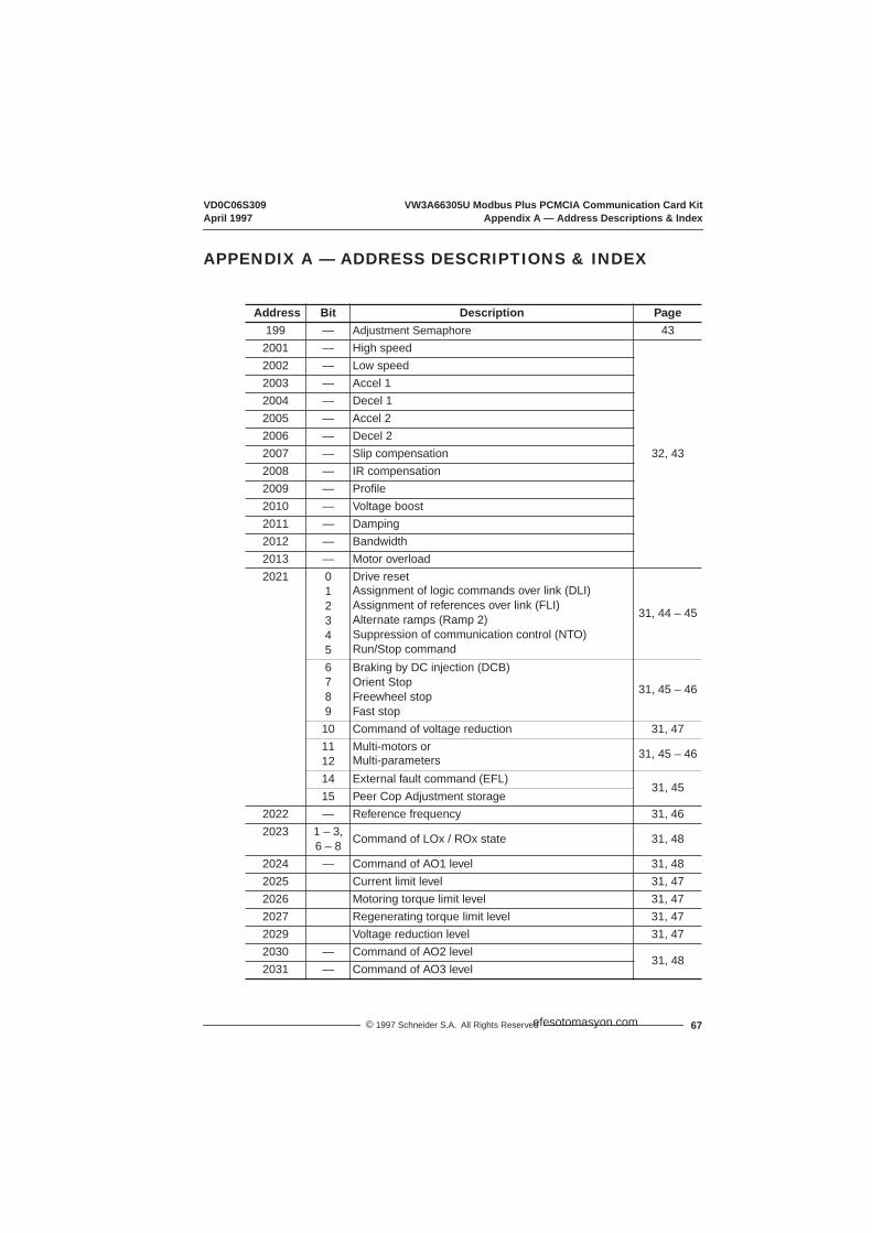
VD0C06S309 VW3A66305U Modbus Plus PCMCIA Communication Card KitApril 1997 Appendix A — Address Descriptions & Index
67© 1997 Schneider S.A. All Rights Reserved
APPENDIX A — ADDRESS DESCRIPTIONS & INDEX
Address Bit Description Page199 — Adjustment Semaphore 43
2001 — High speed
32, 43
2002 — Low speed2003 — Accel 12004 — Decel 12005 — Accel 22006 — Decel 22007 — Slip compensation2008 — IR compensation2009 — Profile2010 — Voltage boost2011 — Damping2012 — Bandwidth2013 — Motor overload2021 0
12345
Drive resetAssignment of logic commands over link (DLI)Assignment of references over link (FLI)Alternate ramps (Ramp 2)Suppression of communication control (NTO)Run/Stop command
31, 44 – 45
6789
Braking by DC injection (DCB)Orient StopFreewheel stopFast stop
31, 45 – 46
10 Command of voltage reduction 31, 471112
Multi-motors orMulti-parameters 31, 45 – 46
14 External fault command (EFL)31, 45
15 Peer Cop Adjustment storage2022 — Reference frequency 31, 462023 1 – 3,
6 – 8 Command of LOx / ROx state 31, 48
2024 — Command of AO1 level 31, 482025 Current limit level 31, 472026 Motoring torque limit level 31, 472027 Regenerating torque limit level 31, 472029 Voltage reduction level 31, 472030 — Command of AO2 level
31, 482031 — Command of AO3 level
efesotomasyon.com
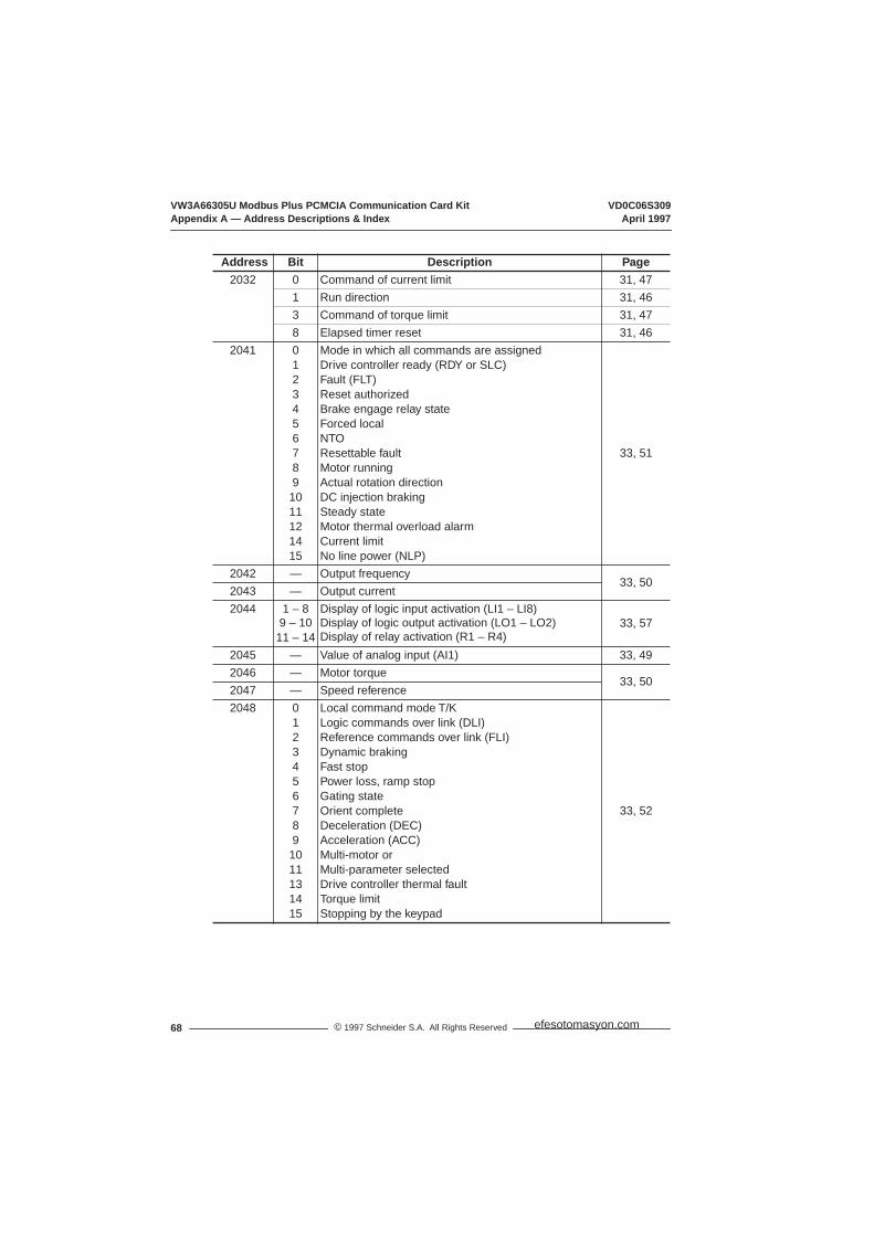
VW3A66305U Modbus Plus PCMCIA Communication Card Kit VD0C06S309Appendix A — Address Descriptions & Index April 1997
© 1997 Schneider S.A. All Rights Reserved68
2032 0 Command of current limit 31, 471 Run direction 31, 463 Command of torque limit 31, 478 Elapsed timer reset 31, 46
2041 01234567891011121415
Mode in which all commands are assignedDrive controller ready (RDY or SLC)Fault (FLT)Reset authorizedBrake engage relay stateForced localNTOResettable faultMotor runningActual rotation directionDC injection brakingSteady stateMotor thermal overload alarmCurrent limitNo line power (NLP)
33, 51
2042 — Output frequency33, 50
2043 — Output current2044 1 – 8
9 – 1011 – 14
Display of logic input activation (LI1 – LI8)Display of logic output activation (LO1 – LO2)Display of relay activation (R1 – R4)
33, 57
2045 — Value of analog input (AI1) 33, 492046 — Motor torque
33, 502047 — Speed reference2048 0
1234567891011131415
Local command mode T/KLogic commands over link (DLI)Reference commands over link (FLI)Dynamic brakingFast stopPower loss, ramp stopGating stateOrient completeDeceleration (DEC)Acceleration (ACC)Multi-motor orMulti-parameter selectedDrive controller thermal faultTorque limitStopping by the keypad
33, 52
Address Bit Description Page
efesotomasyon.com

VD0C06S309 VW3A66305U Modbus Plus PCMCIA Communication Card KitApril 1997 Appendix A — Address Descriptions & Index
69© 1997 Schneider S.A. All Rights Reserved
2049 012345678910111213
JogShutdown completeCycle completeAlternate rampAuto/ManualFrequency level 1 attainedFrequency level 2 attainedCurrent level 1attainedCurrent level 2 attainedThermal level 1attainedThermal level 2 attainedNo ramp followRun output command (bypass)Rotation direction
33, 53
2050 045
Drive faulted, stoppedState of Adjustment SemaphoreState of Command Semaphore
33, 53
2051 — Display of fault causing trip 33, 602052 — Display of present faults 33, 612053 — Output power
33, 50
2054 — Output voltage2055 — Line voltage2056 — Bus voltage2057 — Motor thermal state value2058 — Drive controller thermal state value2059 — Elapsed time (hours)
33, 552060 — Elapsed time (minutes)2061 — Output speed (rpm)2062 — Machine frequency reference (customer units)2063 — Machine frequency (customer units)2064 — Value of analog input AI2
33, 492065 — Value of analog input AI32066 — Value of analog input AI42067 — Value of AO1
33, 562068 — Value of AO22069 — Value of AO32070 — Speed ramp output
33, 502072 — Nominal motor voltage range2075 — Number of motor or parameter set selected
542076 — Cycles step number in progress2077 — Preset speed number in progress
Address Bit Description Page
efesotomasyon.com
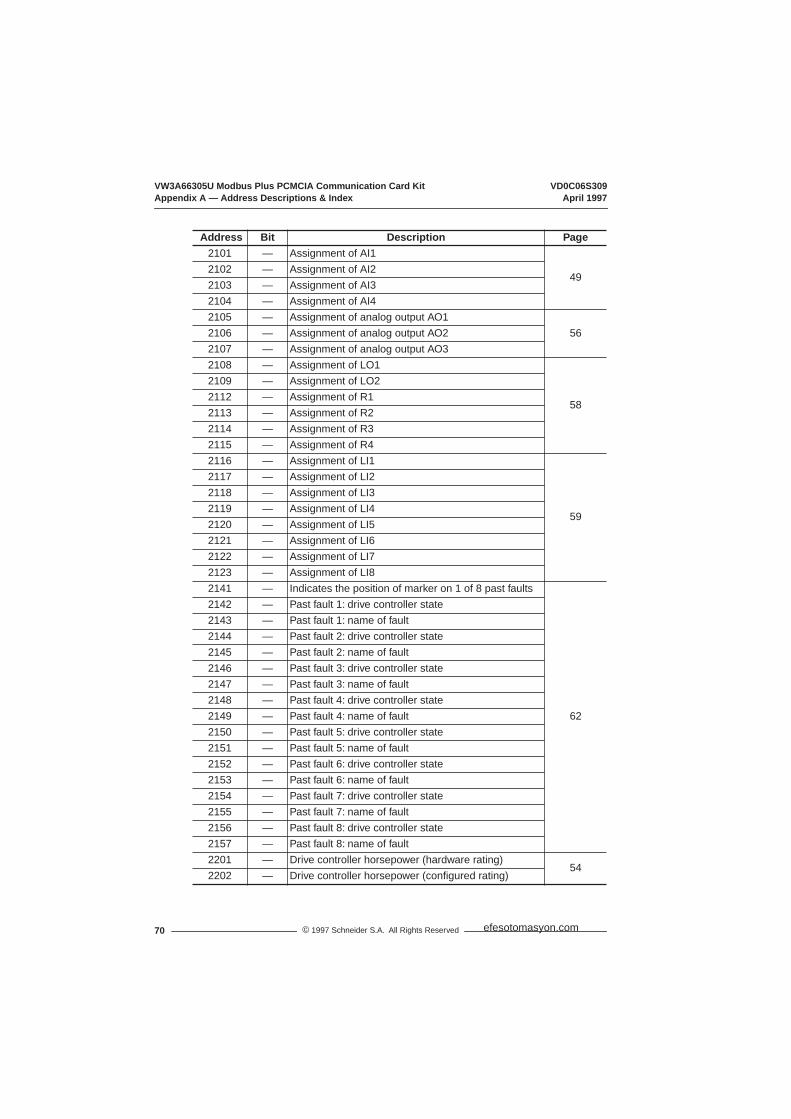
VW3A66305U Modbus Plus PCMCIA Communication Card Kit VD0C06S309Appendix A — Address Descriptions & Index April 1997
© 1997 Schneider S.A. All Rights Reserved70
2101 — Assignment of AI1
492102 — Assignment of AI22103 — Assignment of AI32104 — Assignment of AI42105 — Assignment of analog output AO1
562106 — Assignment of analog output AO22107 — Assignment of analog output AO32108 — Assignment of LO1
58
2109 — Assignment of LO22112 — Assignment of R12113 — Assignment of R22114 — Assignment of R32115 — Assignment of R42116 — Assignment of LI1
59
2117 — Assignment of LI22118 — Assignment of LI32119 — Assignment of LI42120 — Assignment of LI52121 — Assignment of LI62122 — Assignment of LI72123 — Assignment of LI82141 — Indicates the position of marker on 1 of 8 past faults
62
2142 — Past fault 1: drive controller state2143 — Past fault 1: name of fault2144 — Past fault 2: drive controller state2145 — Past fault 2: name of fault2146 — Past fault 3: drive controller state2147 — Past fault 3: name of fault2148 — Past fault 4: drive controller state2149 — Past fault 4: name of fault2150 — Past fault 5: drive controller state2151 — Past fault 5: name of fault2152 — Past fault 6: drive controller state2153 — Past fault 6: name of fault2154 — Past fault 7: drive controller state2155 — Past fault 7: name of fault2156 — Past fault 8: drive controller state2157 — Past fault 8: name of fault2201 — Drive controller horsepower (hardware rating)
542202 — Drive controller horsepower (configured rating)
Address Bit Description Page
efesotomasyon.com
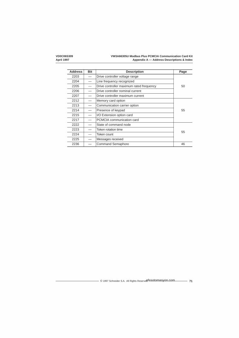
VD0C06S309 VW3A66305U Modbus Plus PCMCIA Communication Card KitApril 1997 Appendix A — Address Descriptions & Index
71© 1997 Schneider S.A. All Rights Reserved
2203 — Drive controller voltage range
502204 — Line frequency recognized2205 — Drive controller maximum rated frequency2206 — Drive controller nominal current2207 — Drive controller maximum current2212 — Memory card option
552213 — Communication carrier option2214 — Presence of keypad2215 — I/O Extension option card2217 — PCMCIA communication card2222 — State of command node
552223 — Token rotation time2224 — Token count2225 — Messages received2236 — Command Semaphore 46
Address Bit Description Page
efesotomasyon.com

VW3A66305U Modbus Plus PCMCIA Communication Card Kit VD0C06S309Appendix A — Address Descriptions & Index April 1997
© 1997 Schneider S.A. All Rights Reserved72
efesotomasyon.com

VD0C06S309 VW3A66305U Modbus Plus PCMCIA Communication Card KitMay 2003 Index
73© 1997 Schneider S.A. All Rights Reserved
INDEX
AAC line
frequency 50overvoltage 60–62
acceleration 43, 52, 62also see ramps
addressing 11
adjustmentregisters 27, 42–43semaphore 34–35, 43parameters 37
alarmsPI 58thermal 51, 58
alternate ramps 43–44, 53
altitude 3
analoginput registers 49inputs (AI1-AI4) 49output registers 48outputs (AO1-AO3) 56
assigninganalog inputs 49analog outputs 56commands 51logic commands 44logic inputs 59logic outputs 58references 44relays 58
at speed 58
attenuation 13
ATV66current 50display status 52–54documentation 2fault registers 60–62horsepower 54identification 22reset 44terminals 5–6thermal state 50, 58voltage range 50
auto run 59
auto test 62
auto/manual 53, 58–59PI 59
Bbandwidth 43
brakingDC injection 45, 51, 62dynamic 52, 62regenerative 62relay state 51release 58
bridge multiplexers 9
buscable length 9, 12faults 60–62LED 4, 6measuring voltage 4, 6network 12voltage 50
buttoneject 7
bypass 53, 58–60, 62
Ccabling
drop 13–14, 16–19electrical interference 13environmentalrequirements 12grounding 8–9inspecting continuity 21inspecting installation 20network 12–14routing 8, 13, 15specifications 3tap devices 12–19trays 13trunk 13–14, 16–19trunk and drop 21
capacitorsmeasuring voltage 4
cardsalso see modulesmemory 55PCMCIA 1, 7, 23, 26, 55
commandnode 55semaphore 34–35, 46, 53
commandsassigning 51keypad 39limit registers 47local 26, 37, 52output registers 48over network 37parameters 37registers 27, 44–48remote 26run 39, 45serial link 39stop 39, 45terminal strip 39
efesotomasyon.com

VW3A66305U Modbus Plus PCMCIA Communication Card Kit VD0C06S309Index May 2003
© 1997 Schneider S.A. All Rights Reserved74
communicationcarrier module 1, 23, 55distributed I/O 9links 2, 10menu 23monitoring 44peer-to-peer 9
configuration 22, 26, 62parameters 23
connectorscable 12–1468-pin 79-pin 3, 7
controlloss of 10, 45
control supply 60, 62
controllersee ATV66see drive controller
counttoken 55
currentdrive controller 50level 53, 58limit 51, 58–59, 62output 50
customer fault 59–60, 62
cycles 53–54, 59complete 58fault 58
Ddamping 43
dataaccessing 36order 38precautions 41range 36structures 36units 36
DC bus 60–62
DC injection braking (DCB)45, 51, 62
deceleration 43, 52, 62also see ramps
desat 60, 62
diagnostics 25
dimensionstap layout 15
direction 51, 53assigning to output 58
displayanalog inputs 49analog outputs 56command node status 55cycle 54drive status 52–54elapsed time 55fault 51fault history 62faults 60frequency 50horsepower 54input state 57LI1-LI8 assignments 59machine frequency 55message status 55motor selected 52, 54output assignment 58output speed 55output state 57parameter set 52, 54parameters 37power 50present faults 61preset speed 54registers 49–62relay assignment 58relay state 57SLC/local 51speed 50thermal state 50token status 55torque 50voltage 50
DLI 39, 44, 52
documentation 2
drive controllercurrent 50display status 52–54fault registers 60–62horsepower 54identification 22ready 51reset 44thermal fault 52thermal state 50voltage range 50
drop cableconnecting 18, 20connecting outer shield wire 20grounding 20labeling 20routing 14selecting 18wiring 19
drop cabling 13–14, 16–19
dynamic braking 52, 60, 62
EEFL
see external fault
eject button 7
elapsed time 55
electrical interface 3
emergency stop 2, 10
enablingjog 58run 59
examplescable tap 14connecting drop cable 19end site taps 17grounding 9in-line taps 16
efesotomasyon.com
VD0C06S309 VW3A66305U Modbus Plus PCMCIA Communication Card KitMay 2003 Index
75© 1997 Schneider S.A. All Rights Reserved
examples (cont’d)network 10, 34network cabling 14token sequences 11using semaphore 35
external fault 45
Ffast stop 45–46, 52
faultscontrol supply 60, 62customer 59–60, 62display word 51dynamic braking 60, 62external 45feedback loss 60, 62ground 60, 62history 62horsepower 60, 62loss of follower 60, 62memory 60, 62motor overload 60, 62overspeed 60, 62overtemperature 60, 62phase loss 60, 62precharge 60, 62register 60–61registers 60reset 59resettable 51screen 23serial link 23, 60–64short circuit 60, 62state 58thermal 52time-out 60, 62transistor 60, 62±15 V input 60, 62
feedbackPI 58
feedback loss 58, 60–62
firmware version 2, 22
FLI 39, 44, 52
FLTsee faults
forced local 26, 38–39, 51,59
forward 58–59
freewheel stop 45–46
frequencylevel 53, 58line 50output 50reference 46, 55
F1 function key 26
Ggating state 52
global data 33transmission 11
grounding 8–9, 60, 62drop cable 20
Hhigh speed 43
horsepower 54, 60, 62
humidity 3
Iidentification 22
input phase loss 60–62
inputsanalog 49logic 57, 59process 59sequence 59
installation 3, 7
interfaceelectrical 3
interference 13
IR compensation 43
isolation 3
I/O Extension module 1, 22,55
Jjog 53, 58–59
jumperscable taps 14
Kkeypad
command 26, 39, 58–59presence of 55stopping with 52
knockout 7
LLEDs 25
DC bus 4, 6
levelcurrent 53, 58frequency 53thermal 53
limitcurrent 51, 58–59, 62registers 47torque 52, 58
linefaults 62frequency 50voltage 50
linkassigning commands over44, 52assigning references over44, 52
efesotomasyon.com

VW3A66305U Modbus Plus PCMCIA Communication Card Kit VD0C06S309Index May 2003
© 1997 Schneider S.A. All Rights Reserved76
local 26, 37, 39, 52, 59
logiccommands
assigning over link 44,52
inputs (LI1-LI8) 57, 59output registers 48outputs (LO1,LO2) 57–58
lossfeedback 58, 60follower 58, 60of control 10phase 61
loss of feedback 62
loss of follower 62
low speed 43
Mmains
no power 51
manual 53
memorycard 55failure 60, 62
menusalso see screenscommunication 23forced local 26power up 22
messages 27, 55status 55
Modbus Plus 16, 27, 40
modulesCommunication Carrier 1,23, 55display status 55displaying 22installation precautions 22I/O Extension 1, 55
motorrunning 51selecting 46, 52
motorsdisplay selection 52multiple 45, 52overload 43, 60–62selecting 46, 59short circuit 60, 62thermal overload alarm 51thermal state 50torque 50voltage range 50
mountingtap 15
MSTR instruction 28–30
multi-motors 45–46, 52
multi-parameters 45–46, 52
NNEMA safety standards 2,10, 41
networkbridge multiplexers 9bus cable 12cabling 14commanding over 37example 10node devices 9performance 35–36physical 12security 35tap devices 13token sequence 11token sequences 11
next step 59
NLP 51
no ramp follow 53, 58
node devicesaddressing 11display status 55drop cables 14maximum number 9, 12
NTO 36, 44, 51, 63
Oopen transistor 60, 62
operatingshock 3temperature 3
orient 52, 58–59stop 45
outputcurrent 50frequency 50logic 57phase loss 60–62power 50speed 55voltage 50
outputsanalog 48, 56logic 48, 58
overload 60–62alarm 51motor 43
overspeed 58, 60–62
overtemperature 60–62
overtravel stop 2, 10
overvoltage 60–62
PPA terminal 5–6
parametersadjustment 37command 37configuration 23display 37display selection 52multiple 45, 52selecting 46, 52types 37
efesotomasyon.com

VD0C06S309 VW3A66305U Modbus Plus PCMCIA Communication Card KitMay 2003 Index
77© 1997 Schneider S.A. All Rights Reserved
PCMCIAcable 8card 1, 7, 23, 26, 55configuration parameters23grounding 8installing kit 7kit part no. 1removing kit 7specifications 3status 25
Peer Cop 30–32adjustment storage 45
phase loss 60–62
PIalarm 58reverse speed 59feedback 58input assignment 49output assignment 56
powerdisconnecting 4loss 52NLP 51no line power 62output 50supply 60, 62
power upmenu 22values 37
precautions 2–4, 10, 22, 39,41, 44–45
precharge failure 60–62
preset speed 54, 59
process input 59
process time-out 60, 62
profile 43
Rramps 44, 52–53, 59
alternate 43display register 50
range 36
RDY 51
ready state 58, 62
received 55
receiving 3messages 55
referencesassigning over link 44, 52frequency 46, 55speed 50
registersadjustment 27, 42–43analog input 49analog outputs 56command 27, 45–46command node 55commands 44, 46–48current 50cycle 54description 41, 62display 49–62drive status 52–54elapsed time 55fault 51, 60fault history 62frequency 50horsepower 54index 67, 71input state 57limit command 47LI1-LI8 assignments 59machine frequency 55messaging 55modules installed 55multi-motor 52, 54multi-parameter 52, 54output assignment 58output command 48output speed 55output state 57power 50present fault 61preset speed 54relay assignment 58
registers (cont’d)relay state 57SLC/local 51speed 50thermal state 50token 55torque 50voltage 50
relaysbraking 51command registers 48R1-R4 57–58
remote 26
repeater devices 9, 12
reset 44, 51, 59
resettable fault 51
reverse 58–59
rotationsee direction
rotation time 55
routing cable 8, 13, 15
run 62auto 59autoforward 59autoreverse 59command 39, 45, 58enabling 59no run permissive 62output command 53running state 58
Sscreens
also see menusdrive identification 22fault 23
semaphoresadjustment 43description 34using 35
efesotomasyon.com

VW3A66305U Modbus Plus PCMCIA Communication Card Kit VD0C06S309Index May 2003
© 1997 Schneider S.A. All Rights Reserved78
sequence input 59
sequence time-out 60, 62
serial link 26, 39, 60–61fault 23, 63–64fault protection 44
setpoint 59
shock 3
short circuit 60–62
shutdown 53complete 58
SLC 39, 51
SLF 23, 62–64
slip compensation 43
softwaresee firmware
specificationscable 3PCMCIA kit 3
speed 43, 55, 58–59at speed 58overspeed 62preset 54ramp output 50reference 50
split control 44
start cycle 59
status 25
steady state 51, 62
step locking 59
stopby keypad 52command 39, 45, 59controlled 59emergency 2, 10fast 45–46, 52freewheel 45–46normal 45–46orient 45overtravel 2, 10
storage temperature 3
storingPeer Cop adjustment 45
Ttachometer 60, 62
tap devices 12–19connecting
end sites 16in-line sites 16
dimensions 15jumpers 13, 14, 16mounting 15terminals 17, 19
temperaturedisplay 50operating 3overtemperature 60–62storage 3
terminalcommand 26, 39, 58–59
terminals 5–6
test 25, 62
thermalalarm 51, 58DB fault 62fault 52level 53, 58state 50
time 55
time-out 36, 55, 60, 62
tokenpassing 11sequences 11status 55
torquelimit 52motor 50
torque limit 58
transistor short circuit 60, 62
transmissiondelays 2, 10
trunkselecting cable 16
trunk and drop 21mounting taps 15
trunk cable 14, 16connecting 16
to end sites 16to in-line taps 16
trunk cabling 13–14, 16–19
Uundervoltage 60–62
units 36
efesotomasyon.com

VD0C06S309 VW3A66305U Modbus Plus PCMCIA Communication Card KitMay 2003 Index
79© 1997 Schneider S.A. All Rights Reserved
Vvalue
analog outputs 56
versionfirmware 2
voltageboost 43bus 50drive controller 50faults 60–62line 50measuring 4, 6motor 50output 50overvoltage 60–62reduction 59undervoltage 60–62
VW3A66201T module 1
VW3A66202 module 1, 23
VW3A66205 module 1, 23
VW3A66301 module 1
Wwiring
trunk cable 17–19
wordsalso see Appendix Adisplay 49, 62structure 36
writingaccess protection 38reserved registers 39, 41
Numerics68-pin connector 7
9-pin connector 7
Symbols– terminal 5–6
+speed/-speed 59
±15 V input 60, 62
efesotomasyon.com

VW3A66305U Modbus Plus PCMCIA Communication Card Kit VD0C06S309Index May 2003
© 1997 Schneider S.A. All Rights Reserved80
efesotomasyon.com

Merlin Gerin Square D Telemecanique
VD0C06S309 April 1997 Printed in USA
© 1997 Schneider S.A. All Rights Reserved
efesotomasyon.com