aluminium two stage actuators
TRANSCRIPT

ALUMINIUMTWO STAGEACTUATORSCATALOGUE
ANNIVERSARY2001 / 2021
th


ALUMINIUMTWO STAGEACTUATORSCATALOGUE
ANNIVERSARY2001 / 2021
th


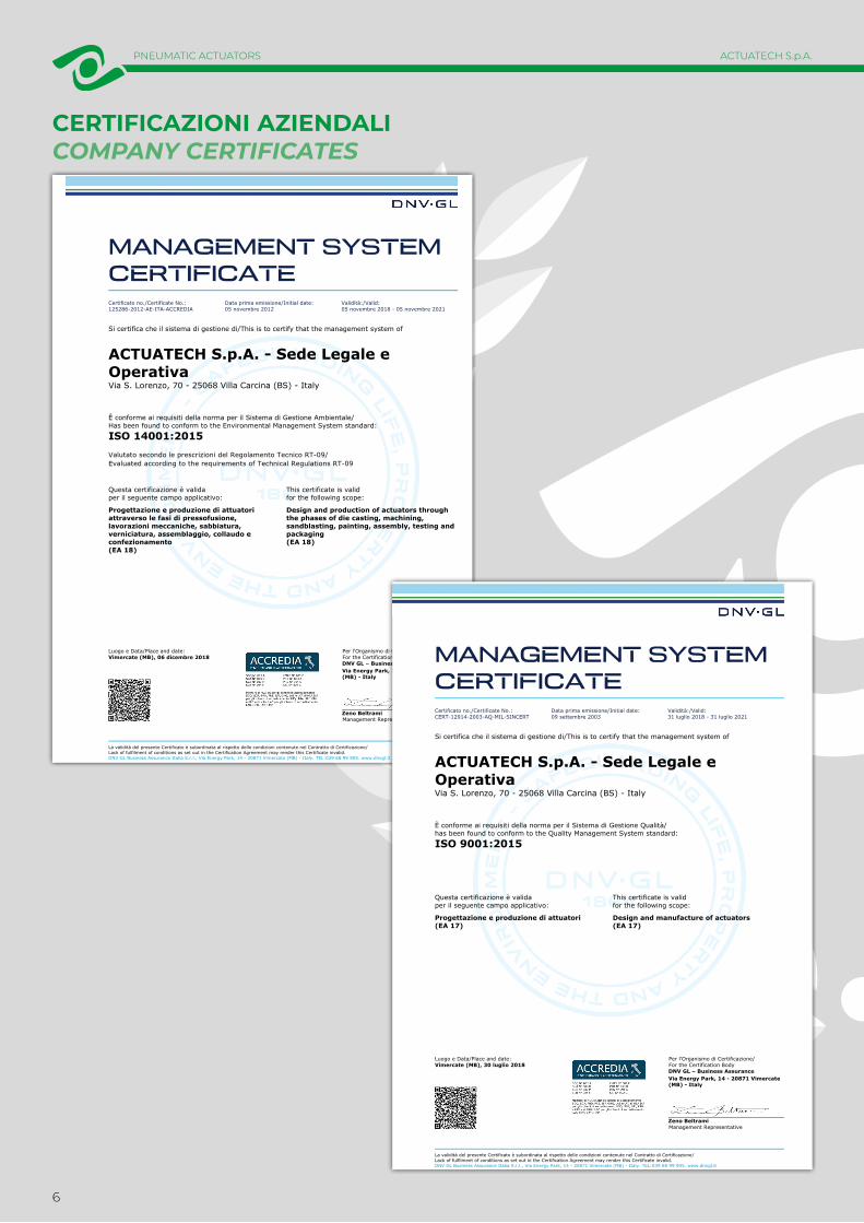
CERTIFICAZIONI AZIENDALICOMPANY CERTIFICATES
Luogo e Data/Place and date:Vimercate (MB), 06 dicembre 2018
Per l'Organismo di Certificazione/For the Certification BodyDNV GL – Business AssuranceVia Energy Park, 14 - 20871 Vimercate(MB) - Italy
Zeno BeltramiManagement Representative
La validità del presente Certificato è subordinata al rispetto delle condizioni contenute nel Contratto di Certificazione/Lack of fulfilment of conditions as set out in the Certification Agreement may render this Certificate invalid. DNV GL Business Assurance Italia S.r.l., Via Energy Park, 14 - 20871 Vimercate (MB) - Italy. TEL:039 68 99 905. www.dnvgl.it
MANAGEMENT SYSTEM CERTIFICATECertificato no./Certificate No.:125286-2012-AE-ITA-ACCREDIA
Data prima emissione/Initial date: 05 novembre 2012
Validità:/Valid:05 novembre 2018 - 05 novembre 2021
Si certifica che il sistema di gestione di/This is to certify that the management system of
ACTUATECH S.p.A. - Sede Legale e OperativaVia S. Lorenzo, 70 - 25068 Villa Carcina (BS) - Italy
È conforme ai requisiti della norma per il Sistema di Gestione Ambientale/Has been found to conform to the Environmental Management System standard:
ISO 14001:2015Valutato secondo le prescrizioni del Regolamento Tecnico RT-09/Evaluated according to the requirements of Technical Regulations RT-09
Questa certificazione è valida This certificate is valid per il seguente campo applicativo: for the following scope:
Progettazione e produzione di attuatori attraverso le fasi di pressofusione, lavorazioni meccaniche, sabbiatura, verniciatura, assemblaggio, collaudo e confezionamento(EA 18)
Design and production of actuators through the phases of die casting, machining, sandblasting, painting, assembly, testing and packaging(EA 18)
Luogo e Data/Place and date:Vimercate (MB), 30 luglio 2018
Per l'Organismo di Certificazione/For the Certification BodyDNV GL – Business AssuranceVia Energy Park, 14 - 20871 Vimercate(MB) - Italy
Zeno BeltramiManagement Representative
La validità del presente Certificato è subordinata al rispetto delle condizioni contenute nel Contratto di Certificazione/Lack of fulfilment of conditions as set out in the Certification Agreement may render this Certificate invalid. DNV GL Business Assurance Italia S.r.l., Via Energy Park, 14 - 20871 Vimercate (MB) - Italy. TEL:039 68 99 905. www.dnvgl.it
MANAGEMENT SYSTEM CERTIFICATECertificato no./Certificate No.:CERT-12914-2003-AQ-MIL-SINCERT
Data prima emissione/Initial date: 09 settembre 2003
Validità:/Valid:31 luglio 2018 - 31 luglio 2021
Si certifica che il sistema di gestione di/This is to certify that the management system of
ACTUATECH S.p.A. - Sede Legale e OperativaVia S. Lorenzo, 70 - 25068 Villa Carcina (BS) - Italy
È conforme ai requisiti della norma per il Sistema di Gestione Qualità/has been found to conform to the Quality Management System standard:
ISO 9001:2015
Questa certificazione è valida This certificate is valid per il seguente campo applicativo: for the following scope:
Progettazione e produzione di attuatori(EA 17)
Design and manufacture of actuators(EA 17)
PNEUMATIC ACTUATORS
6
ACTUATECH S.p.A.

RESPONSABILITÀ SOCIALESOCIAL RESPONSIBILITY
PNEUMATIC ACTUATORS
7
ACTUATECH S.p.A.

ATTUATORI PNEUMATICI ∙ INDICEPag:
10
12
14
1617
18
20
ATTUATORI PNEUMATICI
• Attuatore pneumatico dosatore in alluminio
• Tabelle componenti
• Componenti attuatore pneumatico dosatore: GDD 30 ÷ GDD 480
• Schema funzionamento attuatore pneumatico doppio effetto “GD” • Schema funzionamento attuatore pneumatico semplice effetto “GS”
• Accessori attuatori pneumatici
• Certificati attuatori pneumatici
8
PNEUMATIC ACTUATORS • INDEX ACTUATECH S.p.A.
PNEUMATIC ACTUATORS ∙ INDEXPag:
10
12
14
1617
18
20
PNEUMATIC ACTUATORS
• Aluminium two stage pneumatic actuator
• Components' table:
• Two stage pneumatic actuator components: GDD 30 ÷ GDD 480
• Working plane pneumatic actuator “GD” type • Working plane pneumatic actuator “GS” type
• Pneumatic actuators Accessories
• Pneumatic actuators Certificates
9
PNEUMATIC ACTUATORS • INDEX ACTUATECH S.p.A.

ATTUATORI PNEUMATICIPNEUMATIC ACTUATORS
52 3 41
52341
GD DOPPIO EFFETTO DOUBLE ACTING
GS SEMPLICE EFFETTO SPRING RETURN
PNEUMATIC ACTUATORS
10
ACTUATECH S.p.A.

FEATURES & BENEFITS
1Fasce di tenuta e scorrimento energizzate autolubrificanti.
Energized and self-lubricated strips.
Minor attrito tra pistone e cilindro.
Less friction between piston and cylinder.
Si evita l’incollaggio della guarnizione al cilindro anche dopo lunghi periodi di fermo.
It prevents the bonding of the seal to the cylinder even after long periods of inactivity.
2Slot, bussole e spine con acciaio con durezza maggiore a 50 HRC.
Slots, bushes and pins made by steel with hardness higher than 50 HRC.
Maggior resistenza alle forze presenti all' interno dell'attuatore.
Higher resistance to the forces inside the actuator.
3Attrito volvente tra slot e pistone.
Rolling friction between piston and slot.
Minor attrito.
Less friction.
4
Scotch yoke con attrito volvente (trasformazione del movimento lineare in movimento rotatorio mediante pistone e albero privo di ingranaggi).
Scotch yoke with rolling friction (transforming rotary motion into linear motion using piston and shaft without teeths/gears).
Minor attrito tra pistone e albero con conseguente minor usura dei pezzi.
Reduced friction between piston and shaft with consequently less wear on the relevant parts.
Momento torcente potenziato in fase di apertura e chiusura.
Empowered Breakaway Torque (BTO & BTC).
Minor ingombro rispetto agli attuatori pignone e cremagliera con conse-guente minor spazio necessario.
Smaller volume/size than rack and pinion actuators (with the same torque) therefore less space required for installation.
Minor peso rispetto agli attuatori pignone e cremagliera (-30% Kg/Nm) con conseguenti risparmi sulla realizzazione della struttura dell'impianto.
Less weight than the rack and pinion (-30% kg / Nm), with consequent savin-gs on the construction sizing of the plant/equipment.
Minor consumo d'aria rispetto agli attuatori pignone e cremagliera (-40% aria cm3/Nm doppio effetto e -20% aria cm3/Nm semplice effetto) con conseguente minor carico di lavoro del compressore o possibilità di utilizzo di un compressore con dimensioni ridotte.
Lower air consumption compared to the rack and pinion actuators (-40% air cm3/Nm for Double Acting and -20% air cm3/Nm for Spring Return) therefore less load on the compressor or the possibility of using a smaller compressor's size.
5Cilindro rullato.
Rolled cylinder.
Minor usura delle fascette energizzate grazie alla bassa rugosità della superficie (0,15 micron Ra).
Less wear of the energized ties thanks to the low roughness of the surface (0.15 micron Ra).
Interfaccia per elettrovalvole NAMUR integrata dal GD15.
From sizes bigger than GD15, NAMUR interface for solenoid valve is already integrated.
Non richiede alcuna basetta supplementare.
No need for extra plate.
Processo produttivo interamente eseguito in ACTUATECH.
100% in- house manufacturing process technology.
Massimo controllo in tutte le fasi di lavorazione.
Maximum control and accuracy in all the stages of the manufacturing process.
Certificato ATEX.
ATEX Certificate.
Ne consente l'installazione in presenza di ambiente potenzialmente esplosivo.
Installation is allowed in a potential explosive environment.
Certificato fino a SIL 3.
Up to SIL 3 Certified.
Elevato livello di sicurezza funzionale garantito.
Guarantee of the high level of functional safety.
PNEUMATIC ACTUATORS
11
ACTUATECH S.p.A.

SCHEDA TECNICA DATA SHEETCodice Code GDD00300311S GDD00300411S GDD00600414S GDD00600514S GDD01060517S GDD02400722S GDD04801027S
Misura Size GDD 30 F03-F05
GDD 30 F04
GDD 60F04
GDD 60F05-F07
GDD 106F05-F07
GDD 240F07-F10
GDD 480F10-F12
A [mm] 355 355 423 423 502 589 702 B [mm] 245 245 278 278 345 416 491C [mm] 29 29 29 29 29 40 55Aria corsa totale Full stroke air (dm3/cycle) 0,17 0,17 0,31 0,31 0,57 1,3 2,46
Aria corsa parziale Partial stroke air (dm3/cycle) 0,18 0,18 0,33 0,33 0,59 1,36 2,55
peso weight Kg. 1,8 1,8 2,8 2,8 4,7 8 14,3
ATTUATORE PNEUMATICO DOSATORE IN ALLUMINIOALUMINIUM TWO STAGE PNEUMATIC ACTUATOR
A
M5
1/8" GAS
C
VDI/VDE 3845 NAMUR
B
VDI/VDE 3845 NAMUR
DATI TECNICI• Angolo di rotazione dosaggio: max 45° .• Angolo di rotazione attuatore: 92° (-1°, +91°).• Momento torcente: vedi tabella degli attuatori relativi.• In ciascun dosatore la cifra che segue la sigla GDD corrisponde al valo-
re della coppia di spunto in Nm. alla pressione di 5,6 bar.
TECHNICAL FEATURES• Metering rotation angle: 45° max. • Max. rotation angle: 92° (-1°, +91°).• Torque (see the corresponding actuator tables).• The code numbers after the letters GDD, always correspond to the breaka-
way torque in Nm at 5,6 bar air supply.
CONDIZIONI DI ESERCIZIO• Temperatura: da -20°C a +80°C.• Pressione nominale: 5,6 bar; massima di esercizio 8,4 bar.• Fluido di alimentazione: aria compressa filtrata secca non necessaria-
mente lubrificata. In caso di lubrificazione usare olio non detergente o compatibile con NBR.
WORKING CONDITION• Temperature: from -20°C to +80°C. • Air supply: 5,6 bar; maximum 8,4 bar.• Actuating media: filtered dry compressed air, not necessarily lubricated.
In case of lubricated air, either non detergent oil or NBR compatible oil, must be used.
PNEUMATIC ACTUATORS > ALUMINIUM TWO STAGE PNEUMATIC ACTUATOR
12
ACTUATECH S.p.A.
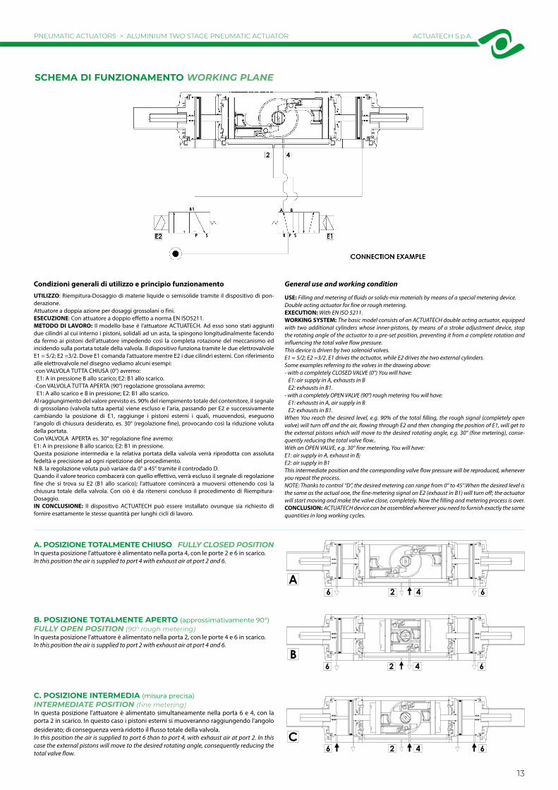
SCHEMA DI FUNZIONAMENTO WORKING PLANE
A6 642
B6426
C6426
Condizioni generali di utilizzo e principio funzionamentoUTILIZZO: Riempitura-Dosaggio di materie liquide o semisolide tramite il dispositivo di pon-derazione.Attuatore a doppia azione per dosaggi grossolani o fini.ESECUZIONE: Con attuatore a doppio effetto a norma EN ISO5211.METODO DI LAVORO: Il modello base é l’attuatore ACTUATECH. Ad esso sono stati aggiunti due cilindri al cui interno i pistoni, solidali ad un asta, la spingono longitudinalmente facendo da fermo ai pistoni dell’attuatore impedendo così la completa rotazione del meccanismo ed incidendo sulla portata totale della valvola. Il dispositivo funziona tramite le due elettrovalvole E1 = 5/2; E2 =3/2. Dove E1 comanda l’attuatore mentre E2 i due cilindri esterni. Con riferimento alle elettrovalvole nel disegno vediamo alcuni esempi:-con VALVOLA TUTTA CHIUSA (0°) avremo: E1: A in pressione B allo scarico; E2: B1 allo scarico.-Con VALVOLA TUTTA APERTA (90°) regolazione grossolana avremo: E1: A allo scarico e B in pressione; E2: B1 allo scarico.Al raggiungimento del valore previsto es. 90% del riempimento totale del contenitore, il segnale di grossolano (valvola tutta aperta) viene escluso e l’aria, passando per E2 e successivamente cambiando la posizione di E1, raggiunge i pistoni esterni i quali, muovendosi, eseguono l’angolo di chiusura desiderato, es. 30° (regolazione fine), provocando così la riduzione voluta della portata.Con VALVOLA APERTA es. 30° regolazione fine avremo:E1: A in pressione B allo scarico; E2: B1 in pressione.Questa posizione intermedia e la relativa portata della valvola verrà riprodotta con assoluta fedeltà e precisione ad ogni ripetizione del procedimento.N.B. la regolazione voluta può variare da 0° a 45° tramite il controdado D.Quando il valore teorico combacerà con quello effettivo, verrà escluso il segnale di regolazione fine che si trova su E2 (B1 allo scarico); l’attuatore comincerà a muoversi ottenendo così la chiusura totale della valvola. Con ciò è da ritenersi concluso il procedimento di Riempitura-Dosaggio.IN CONCLUSIONE: Il dispositivo ACTUATECH può essere installato ovunque sia richiesto di fornire esattamente le stesse quantità per lunghi cicli di lavoro.
General use and working condition
USE: Filling and metering of fluids or solids-mix materials by means of a special metering device. Double acting actuator for fine or rough metering.EXECUTION: With EN ISO 5211.WORKING SYSTEM: The basic model consists of an ACTUATECH double acting actuator, equipped with two additional cylinders whose inner-pistons, by means of a stroke adjustment device, stop the rotating angle of the actuator to a pre-set position, preventing it from a complete rotation and influencing the total valve flow pressure.This device is driven by two solenoid valves.E1 = 5/2; E2 =3/2. E1 drives the actuator, while E2 drives the two external cylinders.Some examples referring to the valves in the drawing above:- with a completely CLOSED VALVE (0°) You will have: E1: air supply in A, exhausts in B E2: exhausts in B1.- with a completely OPEN VALVE (90°) rough metering You will have: E1: exhausts in A, air supply in B E2: exhausts in B1.When You reach the desired level, e.g. 90% of the total filling, the rough signal (completely open valve) will turn off and the air, flowing through E2 and then changing the position of E1, will get to the external pistons which will move to the desired rotating angle, e.g. 30° (fine metering), conse-quently reducing the total valve flow..With an OPEN VALVE, e.g. 30° fine metering, You will have:E1: air supply in A, exhaust in B;E2: air supply in B1This intermediate position and the corresponding valve flow pressure will be reproduced, whenever you repeat the process.NOTE: Thanks to control “D”, the desired metering can range from 0° to 45°.When the desired level is the same as the actual one, the fine-metering signal on E2 (exhaust in B1) will turn off; the actuator will start moving and make the valve close, completely. Now the filling and metering process is over.CONCLUSION: ACTUATECH device can be assembled wherever you need to furnish exactly the same quantities in long working cycles.
A. POSIZIONE TOTALMENTE CHIUSO FULLY CLOSED POSITIONIn questa posizione l'attuatore è alimentato nella porta 4, con le porte 2 e 6 in scarico.In this position the air is supplied to port 4 with exhaust air at port 2 and 6.
B. POSIZIONE TOTALMENTE APERTO (approssimativamente 90°)FULLY OPEN POSITION (90° rough metering)In questa posizione l'attuatore è alimentato nella porta 2, con le porte 4 e 6 in scarico.In this position the air is supplied to port 2 with exhaust air at port 4 and 6.
C. POSIZIONE INTERMEDIA (misura precisa)INTERMEDIATE POSITION (fine metering)In questa posizione l'attuatore è alimentato simultaneamente nella porta 6 e 4, con la porta 2 in scarico. In questo caso i pistoni esterni si muoveranno raggiungendo l'angolo desiderato; di conseguenza verrà ridotto il flusso totale della valvola.In this position the air is supplied to port 6 than to port 4, with exhaust air at port 2. In this case the external pistons will move to the desired rotating angle, consequently reducing the total valve flow.
PNEUMATIC ACTUATORS > ALUMINIUM TWO STAGE PNEUMATIC ACTUATOR
13
ACTUATECH S.p.A.

COMPONENTI ATTUATORE PNEUMATICO DOSATORE: GDD 30 ÷ GDD 480TWO STAGE PNEUMATIC ACTUATOR COMPONENTS: GDD 30 ÷ GDD 480
2223
2126
3334
3230
2829
2724
2520
2223
2126
3432
31
3130
2928
2725
2420
2
10
1211
913
51 4
68
719
3
1415
1617
1310
92
1211
33
PNEUMATIC ACTUATORS > COMPONENTS‘ TABLE
14
ACTUATECH S.p.A.

MA
TER
IALI
M
ATE
RIA
LSPo
sD
enom
inaz
ione
Den
omin
atio
nQ
.tyM
ater
iale
Mat
eria
l
1Ci
lindr
o C
ylin
der
1Le
ga d
i allu
min
io A
lum
iniu
m a
lloy
2Pi
ston
e P
isto
n2
Lega
di a
llum
inio
Alu
min
ium
allo
y
3A
lber
o S
haft
1Ac
ciai
o in
ox S
tain
less
stee
l
4Fo
rcel
la S
cotc
h yo
ke1
Lega
di a
ccia
io S
teel
allo
y
5Bu
ssol
a sc
orrim
ento
sup
port
o B
ush
1Re
sina
ace
talic
a A
ceta
lic re
sin
6Bu
ssol
a di
scor
rimen
to B
ush
1Re
sina
ace
talic
a A
ceta
lic re
sin
7Sp
ina
elas
tica
inte
rna
Int.e
last
ic p
in1
Lega
di a
ccia
io S
teel
allo
y
8Sp
ina
elas
tica
este
rna
Ext
.ela
stic
pin
1Le
ga d
i acc
iaio
Ste
el a
lloy
9Bu
ssol
a ac
ciai
o B
ush
2Le
ga d
i acc
iaio
Ste
el a
lloy
10Pe
rno
Sle
eve
2Le
ga d
i acc
iaio
Ste
el a
lloy
11An
ello
di t
enut
a D
ynam
ic se
al2
Poliu
reta
no P
olyu
reth
an
12O
-rin
g de
l pis
tone
O-r
ing
2G
omm
a ni
trili
ca N
BR
13D
ische
tto
di su
ppor
to S
uppo
rt d
isks
4PT
FE c
aric
car
bo-g
rafit
e
14Se
eger
1Ac
ciai
o in
ox S
tain
less
stee
l
15Ro
ndel
la d
i spe
ssor
amen
to W
ashe
r1
Acci
aio
inox
Sta
inle
ss st
eel
16An
ello
supp
orto
est
erno
Ext
.supp
ort r
ing
1Re
sina
ace
talic
a A
ceta
lic re
sin
17O
-rin
g al
bero
supe
riore
O-ri
ng1
FKM
MA
TER
IALI
M
ATE
RIA
LSPo
sD
enom
inaz
ione
Den
omin
atio
nQ
.tyM
ater
iale
Mat
eria
l
18A
nello
di c
entr
aggi
o C
ente
ring
ring
1Le
ga d
i allu
min
io A
lum
iniu
m a
lloy
19O
-rin
g in
ferio
re a
lber
o O
-rin
g1
FKM
20O
-rin
g te
nuta
tapp
o O
-rin
g2
Gom
ma
nitr
ilica
NBR
21G
rano
blo
ccag
gio
rego
lazi
one
Gru
b sc
rew
2Ac
ciai
o in
ox S
tain
less
stee
l
22Vi
ti sc
rew
s8
Acci
aio
inox
Sta
inle
ss st
eel
23Pr
otez
ione
pro
tect
ion
2Le
ga d
i allu
min
io A
lum
iniu
m a
lloy
24O
-ring
int.t
appo
inte
rmed
io S
uppo
rt b
ush
2FK
M
25Ta
ppo
inte
rmed
io I
nter
med
iate
cap
2Le
ga d
i allu
min
io A
lum
iniu
m a
lloy
26Co
ntro
dado
di r
egol
azio
ne A
djus
ting
nut
2Le
ga d
i allu
min
io A
lum
iniu
m a
lloy
27O
-rin
g es
t.tap
po in
term
edio
O-r
ing
2G
omm
a ni
trili
ca N
BR
28O
-ring
pist
one
ausil
iario
O-ri
ng2
Gom
ma
nitr
ilica
NBR
29Pi
ston
e au
silia
rio A
uxili
ary
pist
on2
Lega
di a
llum
inio
Alu
min
ium
allo
y
30Ci
lindr
o au
sial
iario
Aux
iliar
y cy
linde
r2
Lega
di a
llum
inio
Alu
min
ium
allo
y
31O
-rin
g ta
ppo
final
e O
-ring
2G
omm
a ni
trili
ca N
BR
32Ta
ppo
final
e T
erm
inal
cap
2Le
ga d
i allu
min
io A
lum
iniu
m a
lloy
33O
-rin
g in
tern
e ta
ppo
final
e O
-ring
4FK
M
34G
rano
blo
ccag
gio
prot
ezio
ne G
rub
scre
w2
Acci
aio
inox
Sta
inle
ss st
eel
PNEUMATIC ACTUATORS > COMPONENTS‘ TABLE
15
ACTUATECH S.p.A.

SCHEMA FUNZIONAMENTO ATTUATORE PNEUMATICO “GD” WORKING PLANE PNEUMATIC ACTUATOR “GD” TYPE
ATTUATORE REGOLABILE-ISTRUZIONI PER L’ UTILIZZO ACTUATOR WITH STROKE ADJUSTMENT-INSTRUCTIONS
SCHEMA DI FUNZIONAMENTOImmettendo aria nel foro 4 di alimentazione, i pistoni si muovono verso l’e-sterno e si ha una rotazione oraria, la posizione finale è quella rappresentata nel disegno.
WORKING PLANESupplying air through the air connection 4, the pistons move outwards in a clockwise direction. The above drawing shows the final position.
SCHEMA DI FUNZIONAMENTOImmettendo aria nel foro 2 di alimentazione, i pistoni si muovono verso il centro e si ha una rotazione antioraria, la posizione finale è quella rappresen-tata nel disegno.
WORKING PLANESupplying air through the air connection 2, the pistons move towards the center in an anticlockwise direction. The above drawing shows the final position.
A) Immettere aria nel foro “D” in modo che i pistoni (part. n°1) si vengano a trovare in posizione di finecorsa verso i tappi.B) Togliere il controdado (part. n°3) agendo sulla chiave C.C) Togliere l’aria di alimentazione.D) Con una chiave a brugola agire sulle viti (part. n°2) ed effettuare la limi-tazione di corsa desiderata.N.B. La corsa può essere limitata per un massimo di 10° da 80° a 90°.Altre regolazioni disponibili a richiesta.E) Mettere aria nel foro “D”, verificare che entrambe le viti (part. n°2) siano a battuta contro i pistoni.F) Mettere il controdado (part. n°3) munito di O-ring (part. n°4) per la tenuta tra dado e tappo.
A) Supply air through the air connection D so that the pistons (Part. 1) move to the end-stroke position, towards the caps.B) Remove the counter nut (part. 3) acting on the C key. C) Shut off the air supply.D) Adjust the end stroke as desired, acting on the screws (part 2) with an hexagonal key.Note: maximum adjusting stroke 10°, ranging from 80° to 90°.Other regulations on request.E) Supply air through the air connection D and check that both screws stop the pistons.F) Screw the counter-nut (part 3) and its o-ring (part 4) to keep nut and cap tight.
TAPPOCAP
TAPPOCAP
CHIAVE CKEY C
PNEUMATIC ACTUATORS > WORKING PLANE PNEUMATIC ACTUATOR “GD” TYPE
16
ACTUATECH S.p.A.

SCHEMA FUNZIONAMENTO ATTUATORE PNEUMATICO “GS” WORKING PLANE PNEUMATIC ACTUATOR “GS” TYPE
ATTUATORE REGOLABILE-ISTRUZIONI PER L’ UTILIZZO ACTUATOR WITH STROKE ADJUSTMENT-INSTRUCTIONS
SCHEMA DI FUNZIONAMENTOSenza pressione di alimentazione, nella versione semplice effetto, l’at-tuatore torna automaticamente in posizione di riposo compiendo una rotazione oraria e la posizione finale è quella rappresentata nel disegno. Sul foro 2 è consigliato montare un filtrino onde evitare che polvere o particelle solide possano entrare nella camera del cilindro senza tuttavia impedire il passaggio dell'aria.
WORKING PLANEWithout air supply, the spring return actuator returns to its resting position, rota-ting in a clockwise direction. The drawing shows its final position.We assembling a small filter on the air connection 2 to prevent dust and parti-cles into the cylinder chamber without, however, preventing the passage of air.
SCHEMA DI FUNZIONAMENTOImmettendo aria nel foro 4 di alimentazione, i pistoni si muovono verso l’esterno comprimendo le molle, si ha una rotazione antioraria e la posizione finale è quella rappresentata nel disegno.
WORKING PLANESupplying air through the air connection 4, the pistons move outwards pressing the spring. An anticlockwise rotation takes place and the final position is shown above.
KEY C
CAP CAP
A) Verificare che le molle siano in posizione di riposo osservando la chiave dell’albero (part. n°1) come da disegno e controllando che nel foro “D” non ci sia pressione.B) Togliere i controdadi (part. n°3) agendo sulla chiave C.C) Con un cacciavite avvitare le viti (part. n°2) in senso orario ed effettuare la limitazione di corsa desiderata.N.B. La corsa può essere limitata per un massimo di 10° da 80° a 90°D) Immettere aria nel foro “D” e verificare che entrambe le viti (part. n°2) siano a battuta contro i pistoni (part. n°5).E) Bloccare i controdadi (part. n°3) muniti di O-ring (part. n°4) per la tenu-ta tra controdado, tappo e vite.
A) The springs must be at rest position, the shaft (part. 1) must be as shown in the drawing. Air connection D must not be supplied with air.B) Remove the counter-nuts (part. 3), acting on C key.C) By means of a screwdriver turn screws (part. 2) in a clockwise direction until you obtain the requested end-stroke regulation.Note: maximum adjusting stroke 10°, ranging from 80° to 90°.D) Supply connection D with air pressure and check that both adjusting screws (part. 2) stop the pistons (part. 5).E) Screw the counter-nuts (part. 3) and their O-ring (part. 4) to keep nut and cap tight.
PNEUMATIC ACTUATORS > WORKING PLANE PNEUMATIC ACTUATOR “GS” TYPE
17
ACTUATECH S.p.A.

BOX DI SEGNALAZIONE CON FINECORSALIMIT SWITCH BOX
ELETTROVALVOLESOLENOID VALVES
ELETTROVALVOLE NAMURNAMUR SOLENOID VALVES
OPERATORE MANUALE DI SBLOCCOMANUAL OVERRIDE WITH HAND WHEEL
ACCESSORI ATTUATORI PNEUMATICIPNEUMATIC ACTUATOR ACCESSORIES
18
PNEUMATIC ACTUATORS ACCESSORIES ACTUATECH S.p.A.

FINECORSA DI PROSSIMITA'PROXIMITY LIMIT SWITCHES
FINECORSA ELETTROMECCANICIELECTROMECHANICAL LIMIT SWITCHES
FINECORSA PNEUMATICIPNEUMATIC LIMIT SWITCHES
POSIZIONATORE PNEUMATICOPNEUMATIC POSITIONER
POSIZIONATORE ELETTROPNEUMATICO (SICUREZZA INTRINSECA)
ELECTROPNEUMATIC POSITIONER(INTRINSICALLY SAFE)
FINECORSA ANTIDEFLAGRANTI II2GD ExdIICEXPLOSION PROOF LIMIT SWITCHES II2GD ExdIIC
Per maggiori informazioni consultare Catalogo Accessori ACTUATECH. For more information check the ACTUATECH Accessories Catalogue.
19
PNEUMATIC ACTUATORS ACCESSORIES ACTUATECH S.p.A.

CERTIFICAZIONI ATTUATORI PNEUMATICI PNEUMATIC ACTUATOR CERTIFICATES
EAC - EAC "EX"
Certificazione di conformità del prodotto ai regolamenti tecnici applicabili nell’unione doganale EuroAsec (Russia, Kazakhstan, Bielorussia, Armenia).
Certification of the compliance of the product with the Technical Regulations applicable in the EuroAsec Customs Union (Russia, Kazakhstan, Belarus, Armenia).
ATEX (Pneumatic actuator ATEX compliance)
OMAL progetta e produce i propri prodotti in conformità alla direttiva ATEX, la quale regola l’impiego di apparecchiature in ambienti con atmosfere esplosive.
OMAL designs and manufactures our products in accordance with the ATEX directive, which regulates the use of equipment in explosive atmospheres.
20
PNEUMATIC ACTUATORS CERTIFICATES ACTUATECH S.p.A.

21
PNEUMATIC ACTUATORS CERTIFICATES ACTUATECH S.p.A.

ACTUATECH S.p.A.
Ph. +39 030 8908142 - Fax +39 030 8908143 - [email protected] - www.actuatech.com
HEADQUARTERSVia San Lorenzo, 70 - 25069 Villa Carcina (BS) ITALY
Coordinates:Lat: 45° 39’ 09.6” North; Lon: 10° 11’ 49.5” East
AGTS0021 - 05/21