aluminium ultrahigh vacuum system for the 3 gev tps synchrotron
TRANSCRIPT

Journal of Physics Conference Series
OPEN ACCESS
Aluminium ultrahigh vacuum system for the 3 GeVTPS synchrotron light sourceTo cite this article G Y Hsiung et al 2013 J Phys Conf Ser 439 012034
View the article online for updates and enhancements
You may also likeBRIGHTEST Fermi-LAT FLARES OF PKS1222+216 IMPLICATIONS ONEMISSION AND ACCELERATIONPROCESSESPankaj Kushwaha K P Singh andSunder Sahayanathan
-
Two year operational experience with theTPS vacuum systemY C Yang C K Chan I C Sheng et al
-
Low field low emittance lattice for thestorage ring of Iranian Light Source FacilityH Ghasem F Saeidi and E Ahmadi
-
Recent citationsVakuumkomponenten aus Aluminium fuumlrUHV und XHVUte Bergner et al
-
This content was downloaded from IP address 125162251140 on 13112021 at 0121
Aluminium ultrahigh vacuum system for the 3 GeV TPS synchrotron light source
G Y Hsiung1 C C Chang1 C L Chen1 L H Wu1 C M Cheng1 C K Chan1 Y C Yang1 H P Hsueh1 S N Hsu1 and J R Chen12 1National Synchrotron Radiation Research Center 101 Hsin-Ann Road Hsinchu 30076 Taiwan 2Institute of Biomedical Engineering and Environmental Science National Tsing Hua University Hsinchu 30043 Taiwan
E-mail hsiungnsrrcorgtw
Abstract The 3-GeV Taiwan Photon Source (TPS) is a large accelerator and synchrotron light source of circumference 5184 m The electron storage ring of TPS requires an ultrahigh- vacuum pressure per beam current less than 2times10-10 PamA in the beam duct to maintain a long life of the circulating beam without scattering of ions by residual gases Aluminium alloys used for the beam ducts have a benefit of greater thermal conductivity that simplifies the structure of vacuum vessels built with the cooling components Machining completely free of oil applied to the aluminium chambers followed by cleaning with ozonized water and welding in house provide a precise dimensional control within 03 mm and a clean surface with a small rate ~ 64times10-12 Pa ms of thermal outgassing after baking at 150 degC for 24 h The assembled ion pump with non-evaporable getter pump is capable of evacuating the chamber to a pressure lt 1times10-9 Pa The average pressure inside the duct is expected to be sufficiently small The clean process to manufacture the aluminium ultrahigh vacuum system is described
1 Introduction Designed as a third-generation synchrotron light source with electron-beam energy 3 GeV beam current 400 mA in multi-bunch top-up operation mode circumference 5184 m beam emittance lt 2 nmmiddotrad Taiwan Photon Source (TPS) is under construction and will be installed in 2013 The vacuum system for the electron-storage ring of TPS provides an ultrahigh vacuum of highest quality with average pressure much less than 1times10-7 Pa throughout the beam duct to mitigate the effects of gas scattering of the stored electron beam [1] As the aluminium ultra-high vacuum (UHV) systems for many accelerators have been operated successfully and as manufacturing techniques for aluminium chambers have been established during the construction of the Taiwan Light Source (TLS) operated since 1993 [2] aluminium alloys were selected for TPS for the beam ducts of the electron-storage ring For the 3-GeV TPS the heat load from the synchrotron radiation and the rate of outgassing from photon-stimulated desorption are much greater than for the 15-GeV TLS As the impedance budget for the beam ducts is more stringent and as the dimensional control of vacuum components is more precise new manufacturing techniques for the aluminium beam ducts must be developed to fulfill the requirements of the UHV systems for TPS rather than TLS [3] The design of the aluminium vacuum systems for TPS complies with the following six strategies (1) to accept the large heat load the absorbers are located remotely from the radiation source (2) the beam ducts are designed with inner
6th Vacuum and Surface Sciences Conference of Asia and Australia (VASSCAA-6) IOP PublishingJournal of Physics Conference Series 439 (2013) 012034 doi1010881742-65964391012034
Content from this work may be used under the terms of the Creative Commons Attribution 30 licence Any further distributionof this work must maintain attribution to the author(s) and the title of the work journal citation and DOI
Published under licence by IOP Publishing Ltd 1
apertures sufficient to accommodate the dimensions of the beam stay clear (3) the UHV pumps are located near the gas sources or the absorbers (4) the structures of vacuum components are modified to be smooth with small impedance (5) to maintain the clean qualities of surfaces manufacturing was developed completely free of oil and (6) there is no baking in situ inside the tunnel The design of the vacuum system the manufacturing and the test results are described in the following sections
2 Design of the vacuum system The vacuum system for the electron-storage ring is divided into six-fold super-period systems each comprises four long straight sections with lengths one 12 m and three 7 m and four arc-cell bending sections of lengths 13 ~ 14 m All lattice magnets are gathered in the arc-cell bending sections that yield a limited space to accommodate vacuum chambers and components Figure 1 illustrates the assembly drawing for a typical one-sextant vacuum system with magnets The design of the vacuum chambers must hence utilize the entire space between the magnets to accommodate the beam-dynamic apertures and to allocate photon absorbers beam-position monitors (BPM) vacuum pumps bellows flanges gate valves and supports Besides the constraint from limited space the manufacturing tolerance for all components must be precisely controlled and the cleanliness of the surface must be maintained through all manufacturing The concept of a large bending chamber made of aluminium alloys with ease of machining capability and increased thermal conductivity was adopted to optimize the design that fulfills the specified requirements [4] The layout drawing of a typical vacuum system of a 14-m cell appears in figure 2 To mitigate the impedance and to save space from flanges and bellows the vacuum chambers in the cell are welded to one piece of 14-m sector with only two bellows joined two flanges and two sector gate valves (SGV) join both ends
Figure 1 Assembly drawing for a typical sextant super-period vacuum system with magnets
(a)
(b)
Figure 2 Layout drawing of a 14-m cell vacuum system The beam ducts are composed of two straight chambers S3 and S4 and two bending chambers B1 and B2
Figure 3 Section drawings inside bending chambers (a) B1 and (b) B2
Several issues concerning the optimized design of the cell vacuum system are described as follows The crotch absorber must be located at least 23 m from the source of synchrotron radiation emitted from the upstream bending magnet so that the water-cooled OFHC copper material is capable of accepting the thermal load [5] With this design concept the bending (B-) chamber has a triangular
6th Vacuum and Surface Sciences Conference of Asia and Australia (VASSCAA-6) IOP PublishingJournal of Physics Conference Series 439 (2013) 012034 doi1010881742-65964391012034
2
shape with length about 3 ~ 4 m The crotch absorber installed downstream from the antechamber that produces molecules outgassing from photon-stimulated desorption (PSD) is confined locally to decrease the gases backfilling the beam channel The surface of aluminium chambers is readily machined to an overall precision lt 002 mm Figure 3 shows section drawings inside the (a) B1- and (b) B2-bending chambers The long channels (dark blue) represent the orbital channels for the electron beam Two crotch absorbers and photon stoppers (orange) are located downstream of the B-chambers The circles shown in the antechambers represent the pumping ports near the absorbers to enhance the localized-pumping efficiency The back sides of the B-chambers are partially machined away to fit the chambers inside magnets with clearances about 1 ~ 3 mm from the magnetic poles or coils The orbital channel made with precise machining in the aluminium B-chamber provides a finished smooth surface that minimizes the impedance
As space between the chambers and magnets is tight baking the cell vacuum systems in situ without conflicting with the magnets is impractical all cell vacuum systems must therefore be baked ex situ in the laboratory to achieve an UHV without leakage before installation in the tunnel Without baking in situ the design of the vacuum cells can be simplified which minimizes the quantity of bellows and flanges to mitigate the impedance to avoid shifting of the BPM from thermal stress to decrease the risks of leakage through the baking and to save significantly the long working hours in the tunnel for the baking The cell vacuum systems will be transported from the laboratory to the tunnel and installed on the girders with a conveyance system [6]
The vacuum chambers in the long straight sections comprising pumping-port chambers primary BPM ducts bellows taper chambers and drift chambers will cooperate with the vacuum systems for insertion devices All drift chambers will be made with aluminium extrusions The long straight sections will be installed after positioning the two arc-cell vacuum systems on both ends Baking in situ will be performed for the long straight sections after installation which is easier than baking of the cells
3 Manufacturing
31 Manufacturing of the aluminium vacuum chambers The vacuum beam ducts for the 14-m arc-cell vacuum system are composed of two short straight (S-) chambers S3 and S4 and two bending (B-) chambers B1 and B2 as shown in figure 2 As the manufacturing of S-chambers differs from that of B-chambers the four chambers must be manufactured individually and then welded to form a 14-m sector chamber Figure 4 shows a design drawing of the four chambers to be prepared before welding The manufacturing is described in the following subsections
311 S-chamber The S-chamber comprises the drift chamber the pumping-port chamber the BPM duct and flanges All chambers are made of aluminium alloys for welding to one piece of the S-chamber The straight aluminium tubes other than the BPM duct are made with extrusion All aluminium extruded parts were cleaned with chemical solvents before welding in the clean room The manufacturing of the S-chambers follows a procedure similar to that for TLS [7] The aluminium extruded pipes were machined for pumping holes cooling channel and welding edges After the chemical cleaning the pre-machined pumping port chamber will be inserted into the extruded pipe and welded together with a tungsten-inert-gas (TIG) method to form the drift straight chamber The aluminium BPM duct is precisely machined with a machine free of oil similar to the manufacturing of the B-chamber to be mentioned in the next section The drift chambers and the BPM duct will be aligned on pre-aligned supports and welded to the one piece S-chamber S3 or S4 as shown in figure 4 Photographs of the welded S-chambers appear in figure 5(a)
6th Vacuum and Surface Sciences Conference of Asia and Australia (VASSCAA-6) IOP PublishingJournal of Physics Conference Series 439 (2013) 012034 doi1010881742-65964391012034
3
312 B-chamber The B-chambers are made on welding two halves of aluminium plate of length ~ 4 m The aluminium plates are precisely machined with a machine under numerical control of a computer (CNC) and free of oil in a clean room (class 10000) The ambient temperature is controlled at 25plusmn1 oC and the relative humidity at lt 50 All machining tools must be cleaned with alcohol throughout the work A system to spray pure alcohol (995 ) is developed to cool the aluminium working pieces during machining A system for compressed air free of oil provides super-dry air to the spray system for spraying the alcohol on the working pieces with ultra-low moisture lt 10 ppb The machining of each aluminium plate is divided into three steps -- rough machining to intermediate machining to precise machining with intervening intervals 1 ~ 3 days for stress release The overall deformation after machining is then controlled lt 002 mm Each aluminium plate will be stored in a clean aluminium bag filled with pure dry nitrogen gas and sealed
Figure 4 Design drawing of four chambers including two short straight (S-) chambers S3 and S4 and two bending (B-) chambers B1 and B2 to be welded to a 14-m sector of an arc-cell vacuum chamber
Before the welding of a B-chamber the two halves of machined plates are taken from the sealed dry bag and immersed in a clean vessel filled with the ozonized water (ozone concentration gt 20 ppm) for 30 min then dried with pure nitrogen gas spraying and promptly moved to the clean room The machining in an environment of pure alcohol is similar to the former process for the aluminium B-chambers in TLS [2] but a recent investigation of cleaning with ozonized water of aluminium chambers machined free of oil provides a much smaller rate of thermal outgassing ~ 64times10-12 Pa ms after baking [8] and a smaller yield of photon-stimulated desorption ~ 2times10-5 moleculesphoton [6] that is applicable for the TPS UHV system As the cleanliness of the surfaces must be maintained and the rate of growth of oxidation on the aluminium surface must be suppressed throughout the welding process all welding work must be done in the dry clean room (class 1000) controlled at temperature 25plusmn1 oC and relative humidity lt 50 The welding sequence consists of the welding of pumping port with flange welding of half plate with pumping port auto-welding of the B-chamber with two half plates precise machining of the terminal ends of the side ports and welding of B-chamber with the side tube flanges and bellows The overall deformation of B-chambers after welding was lt 01 mm vertical and lt 03 mm transverse Each step in the welding sequence must be inspected for leakage [6] The B-chambers after welding will be promptly evacuated and sealed in vacuum The photographs of the welded B-chambers and the welding work appear in figure 5(b) and 5(c) respectively
32 Welding of the 14-m vacuum cell Before joining the chambers the supports for the chambers are installed on the girders and aligned to precision lt 01 mm with a laser tracker All major supports are made of thick aluminium plates With a precisely machined base plane provided on the girders the aluminium plates can be well positioned within 01 mm without adjustment mechanism When those supports have been aligned and fixed on the girders the B1 and B2 chambers are placed on the aluminium supports and fixed with the positioning guide pins near the BPM of B1 and B2 chambers respectively The S3 and S4 chambers are then placed on the supports The four chambers are aligned with a laser tracker to precision lt 01 mm then fixed on the supports As the surfaces of the aluminium chambers and aluminium supports
6th Vacuum and Surface Sciences Conference of Asia and Australia (VASSCAA-6) IOP PublishingJournal of Physics Conference Series 439 (2013) 012034 doi1010881742-65964391012034
4
near the adjacent interface are both precisely machined the positioning of chambers on the pre-aligned supports can be done quickly without adjustment After positioning the chambers the TIG welding to join the four chambers to one sector is performed on site on the girders and then evacuated to test the leakage With this efficient welding a full cell of a 14-m vacuum chamber proved to be precisely aligned on the girders and leak-tight The 14-m cell is then exposed to the atmosphere with pure nitrogen gas for the installation of vacuum components including ten BPM flanges two sector-gate valves (SGV) two front-end valves (FEV) two pumping-gate valves (PGV) four ion pumps (IP) ten non-evaporable getter (NEG) pumps three extractor ionization gauges (IG) four turbo-molecular pumps (TMP) etc and evacuated for leak testing Figure 6 presents photographs of the assembly works for the 14-m vacuum cell on the girders After installation of two crotch absorbers and two photon stoppers the vacuum system of the entire cell must be baked at 150 oC for 24 h to attain the required UHV pressure
(a)
(b)
(c)
Figure 5 Photographs of (a) welded S-chambers (b) welded B-chambers and (c) welding works for the B-chamber
Figure 6 Assembly work for the 14-m vacuum cell on the girders
4 Test results
41 Baking test for a 14-m vacuum cell The average pressure in the beam duct is determined by the rate of thermal outgassing of the aluminium vacuum chambers and the efficient pumping performance at UHV The baking test for a 14-m cell vacuum system is performed on reaching 150 oC and kept for 24 h for inspection of the outgassing behavior Before cooling the IP will be switched on to refresh the cathodes with a high- temperature ion-sputtering effect and the gauges degassed more than 20 min all NEG pumps will then be simultaneously activated to 450 oC for 1 h when all IP must be turned off to avoid pumping contamination from the outgassing of NEG during activation After the NEG activations the triode IP are switched on and maintained at a fixed mode of high voltage (-7 kV) applied for more efficient discharge-cleaning of the cathodes The entire system is then cooled uniformly All bolts and nuts of the flanges will be tested for torque and tightened as required at temperature ~ 60 oC during cooling Figure 7 shows a photograph of one cell baking ex situ in the laboratory the pumping curve through
6th Vacuum and Surface Sciences Conference of Asia and Australia (VASSCAA-6) IOP PublishingJournal of Physics Conference Series 439 (2013) 012034 doi1010881742-65964391012034
5
the baking and the mass spectrum after baking The ultimate pressure after baking attained 6times10-9 Pa indicated in figure 7(b) The major residual gases comprising H2 CO H2O and CO2 are shown in figure 7(c)
(a) (b) (c)
Figure 7 Baking ex situ of one cell in the laboratory (a) preparation for baking (b) pumping curve (c) mass spectrum after baking
42 Baking test for the IP and NEG pumping assembly The combination of triode ion pump (IP) (200 Ls) and non-evaporable getter (NEG) pump (350 Ls) was designed to fit in the spaces between the magnets and located nearer the major outgassing sources from the photon absorbers to enhance the highly efficient pumping performance An experimental system was set up as shown in figure 8(a) for the UHV-pumping test The ion pump was connected to the chamber at the bottom Two side ports of the ion pump were mounted with the NEG pump and the roughing pump To measure the pressure an extractor ion gauge labeled G1 in fig 8 was installed in the chamber Vacuum gauges G2 ~ G6 of other kinds were mounted near the chambers for comparison The performance of pumping and the gauge measurements in the UHV were evaluated through the pumping and the baking After evacuation of the system baking for degassing and NEG activation the ultimate pressure (G1) attained ~ 8times10-10 Pa (~ 6times10-12 Torr as shown in fig 8(b)) The major residual gases comprised H2 CO and CO2 When the system was isolated from the turbo-molecular pump and the ion pump shut off the pressure increased to ~ 4times10-9 Pa about five times as great with the pressure increasing from the residual outgassing of methane (CH4) The NEG pump actively pumps all gases but noble gases such as CH4 The pressure recovered to 8times10-10 Pa after switching on the IP to reveal the workable pumping at 10-10 Pa
(a) (b)
Figure 8 (a) Experimental setup of vacuum chambers with ion pump NEG pump and gauges (G1 ~ G6) (b) Pumping curve
6th Vacuum and Surface Sciences Conference of Asia and Australia (VASSCAA-6) IOP PublishingJournal of Physics Conference Series 439 (2013) 012034 doi1010881742-65964391012034
6
5 Conclusion The design concepts manufacture and test results for the aluminium ultra-high vacuum system for the TPS synchrotron light source are described CNC machining completely free of oil with a system to spray pure alcohol working for machining the aluminium B-chambers and BPM ducts in a dry clean room provides a precise control of dimension with tolerance lt 002 mm and a clean surface After the machining the machined piece is promptly sealed in a clean aluminium bag filled with pure N2 gas for storage The aluminium parts are not removed until the welding process proceeds in the clean room Cleaning with ozonized water applied for aluminium parts before welding provides a least rate of thermal outgassing 64times10-12 Pa ms The aluminium chambers for the 14-m cell vacuum systems are welded on the pre-aligned girder supports in the clean room for stringent dimensional control and cleaning quality of the vacuum chambers The overall tolerance for the deformation and the alignment for the 14-m vacuum chambers is controlled within 03 mm All work for the welding in house and the vacuum assembly were performed in a clean room The pumping test of an experimental system assembled with IP and NEG and a baking test for the 14-m vacuum cell have attained a pressure less than 6times10-9 Pa in UHV The result proves that the design of the aluminium UHV system is acceptable for the TPS synchrotron light source
Acknowledgements We thank colleagues in the Precision Mechanical group for providing the pre-aligned girders for the installation work for the 14-m vacuum cells and colleagues in the Vacuum group for their collaborative hard work on welding assembling carrying and baking processes
References [1] Hsiung G Y Chan C K Hsueh H P Yang T L Kuan C K Chang C C Hsu S N Yang C Y
Chen C L and Chen J R 2007 CP879 Synchrotron Radiation Instrumentation Ninth International Conference 62
[2] Chen J R Chen G S Wang D J Hsiung G Y and Liu Y C 1990 Vacuum 41(7-9) 2079 [3] Hsiung G Y Chan C K Chang C C Chen Y B Hsueh H P Chen C L Yang C Y Shu S N
Cheng C M Kuan C K Sheng I C and Chen J R 2008 Journal of Physics Conference Series 100 092014
[4] Hsiung G Y Chan C K Chang C H Hseuh H P Yang T L and Chen J R 2006 Proceedings of EPAC 2006 THPLS064 3433
[5] Sheng I C Cheng Y T Kuan C K Hsiung G Y Chen J R and Yang C Y 2010 Proceedings of IPACrsquo10 TUPEA079 1506
[6] Chen J R Hsiung G Y Chang C C Chen C L Chan C K Cheng C M Yang C Y Wu L H and Hsueh H P 2010 J Vac Sci Technol A28(4) 942
[7] Liu Y C and Chen J R 1991 AIP Conference proceedings 236 173 [8] Chan C K Hsiung G Y Chang C C Chen Rouge Yang C Y Chen C L Hsueh H P Hsu S N
Liu Ivan and Chen J R 2008 Journal of Physics Conference Series 100 092025
6th Vacuum and Surface Sciences Conference of Asia and Australia (VASSCAA-6) IOP PublishingJournal of Physics Conference Series 439 (2013) 012034 doi1010881742-65964391012034
7
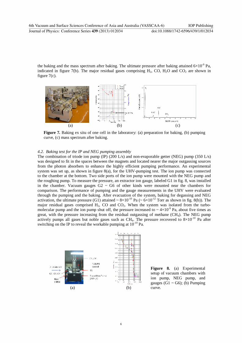