amateur radio antenna installations for orange … amateur radio antenna installations for orange...
TRANSCRIPT

1
Amateur Radio Antenna Installations for Orange County Hospitals
HDSCS supports Orange County hospitals using frequencies on threeAmateur Radio bands: 144, 220 and 440 MHz. The recommended antennathat provides optimum communications on all three bands is Model CX-333by NCG Company (Comet Antennas). This high-gain antenna mountsvertically at its base, is 10 feet tall and weighs 4 pounds. Price is about $180.
Some early hospital installations have discone type antennas, which cover avery wide frequency range. Because of their low gain and sensitivity to out-of-band signals and interference, we recommend replacing discone antennaswith Model CX-333 when practical.
Coaxial cable ("coax") connects the antenna to the location where radio(s)will be operated. Choice of the proper cable is important. Because thefrequencies are very high (VHF and UHF), the cable will dissipate (lose)some of the received and transmitted signals and power. Therefore, low-losscable is a necessity and the cable run must be as short as practical. For runsof up to 150 feet, type LMR-400 UltraFlex cable (part number LMR-400-UF)by Times Microwave Systems is recommended. The jacket (outer covering)of this cable is outdoor-rated. Cost of this cable is approximately $1.50 perfoot. Typical OC hospital installations have about 75 feet of this cable.
LMR-400-UF is the cable that was chosen for procurement with grant fundsby the County of Orange for use in HDSCS installations. It is the most flexible version of this type of cable.Nevertheless, bends must be gradual. Kinking will severely damage its VHF/UHF electrical properties.
LMR-400-UF is not plenum-rated. If plenum-rated cable is mandated foryour installation, a fire-rated version of this cable (LMR-400-LLPL) isavailable at approximately $5.60 per foot. It has an orange jacket that issuitable only for indoor applications. Times Microwave states that ablack-jacketed outdoor-rated version of this fire-retardant cable is offered,but no price or part number is given and it may not be readily available.As an alternative to purchasing expensive plenum-rated cables, some OChospitals have chosen to run LMR-400-UF within conduit.
If the cable run must be longer than 150 feet, please consult HDSCS. Itmay be necessary to use "hard line" coax, which has very low loss butrequires special installation techniques because of its size and stiffness.LDF4-50A "Heliax" cable by Andrew Corporation is suitable for runs upto 350 feet. Its outside diameter is 0.62 inch and minimum bend radius isfive inches. Price is $2.50 per foot for outdoor rated cable and $3.80/ft forplenum rated (type HL4RP). Special hangars and connectors are requiredat additional cost.
Selecting the Antenna Site
We strongly suggest that the volunteers in the HDSCS Antenna Team beinvolved in the selection of the site for the antenna and routing of the

2
coax. It is important that the antenna be in a clear location, as unobstructed as possible, and at least ten feetaway from other transmitting/receiving antennas. The top of the highest part of the building may seem ideal,and indeed it often is, but it may be unsuitable if it requires the coax run to be excessively long. Sometimes aclear location on a lower roof is a better choice if it significantly reduces the coax length. The antenna baseattaches to a mounting pipe (2" diameter nominal; 2-1/2" diameter maximum) that is supplied by the hospital.The pipe is firmly secured to a rooftop parapet, façade, pipe bracket, etc. The three horizontal radials at thebase of the antenna are important and must be unobstructed.
Installing the Antenna and Coax
Installation of the mounting pipe and running the coaxial cable through walls andceilings is the responsibility of the hospital or its contractor. Once that is complete,the volunteer HDSCS Antenna Team will assemble the antenna, mount it onto thepipe, install connectors onto both ends of the coax, and test the completed antennasystem. HDSCS will supply the connectors (silver plated and Teflon-insulated) foruse with LMR-400 cables.
There are two options for the interior end of the coax. In some hospitals, a typeSO-239 connector is mounted on a box cover plate on a wall, as in the photo at left.There must be space inside the wall for a gradual bend of the cable or a right-angleadapter. The HDSCS operator is expected to bring a short "pigtail" cable ofsuitable length to go from the wall plate to his or her radio equipment.
In places where the cable must run asignificant length from the wall to the radiooperator position, a cable box with cover is
desirable, with extra cable inside. The box can be surface-mounted onthe wall or it can be recessed as in the photo at right.
Sources
NCG antennas and Times Microwave cables are available from HamRadio Outlet, 933 North Euclid Street in Anaheim (714) 533-7373.Andrew Heliax cables, connectors and accessories are available from RFParts Company, 435 South Pacific Street in San Marcos (800) 737-2787.
14 March 2013Hospital Disaster Support Communications System
www.hdscs.orgContact: April or Joe Moell (714) 879-6895
Page 3 is data sheet for CX-333 antennaPage 4 is data sheet for LMR-400-UF coaxPage 5 is data sheet for LMR-400-LLPL coaxData for Heliax cables available on request
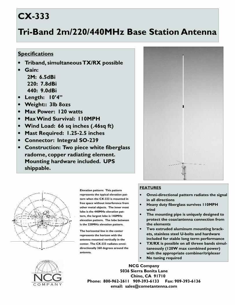
CX-333
Tri-Band 2m/220/440MHz Base Station Antenna
Specifications
• Triband, simultaneous TX/RX possible
• Gain:
2M: 6.5dBi 220: 7.8dBi 440: 9.0dBi • Length: 10’4”
• Weight:: 3lb 8ozs
• Max Power: 120 watts
• Max Wind Survival: 110MPH
• Wind Load: 66 sq inches (.46sq ft)
• Mast Required: 1.25-2.5 inches
• Connector: Integral SO-239
• Construction: Two piece white fiberglass
radome, copper radiating element. Mounting hardware included. UPS shippable.
FEATURES
• Omni-directional pattern radiates the signal
in all directions • Heavy duty fiberglass survives 110MPH
wind • The mounting pipe is uniquely designed to
protect the coax/antenna connection from the elements
• Two extruded aluminum mounting brack-
ets, stainless steel U-bolts and hardware included for stable long term performance
• TX/RX is possible on all threee bands simul-
taneously (120W max combined power) with the appropriate combiner/triplexer
• No tuning required
NCG Company 5036 Sierra Bonita Lane Chino, CA 91710
Phone: 800-962-2611 909-393-6133 Fax: 909-393-6136 email: [email protected]
Elevation pattern: This pattern
represents the typical elevation pat-
tern when the CX-333 is mounted in
free space without interference from
other metal objects. The inner most
lobe is the 440MHz elevation pat-
tern, the largest lobe is 146MHz
elevation pattern. The lobe between
is the 220MHz elevation pattern.
The horizontal line in the center
represents the horizon with the
antenna mounted vertically in the
center. The CX-333 radiates omni-
directionally 360 degrees around the
antenna.

(800) TMS-COAX • www.timesmicrowave.com62
TIMES MICROWAVE SYSTEMS
LMR-®400-UF UltraFlex Communications Coax
LMR
-400
-UF
Part Description
Stock Part Number Application Jacket Color Code LMR-400-UF Indoor/Outdoor TPE Black 54040
• LMR®- UltraFlex has a stranded center conductor and rubber outer jacket designed for multiple bending/flexing cycles. It is used for both indoor and outdoor applications.
• Flexibility and bendability are hallmarks of the LMR-400-UF cable design. The flexible outer conductor enables the tightest bend radius available for any cable of similar size and performance.• Low Loss is another hallmark feature of LMR-400-UF. Size for size LMR has the lowest loss of any flexible cable and comparable loss to semirigid hard-line cables.• RF Shielding is 50 dB greater than typical single shielded coax (40 dB). The multi-ply bonded foil outer conductor is rated conservatively at > 90 dB (i.e. >180 dB between two adjacent cables). • Weatherability: LMR-400-UF cables are designed for outdoor exposure and have a life expectancy in excess of 10 years.
• Connectors: A wide variety of connectors are available for LMR-400-UF cable, including all common interface types, reverse polarity, and solder-on center pins. Most LMR connectors employ crimp outer attachment using standard hex crimp sizes.• Cable Assemblies: All LMR-400-UF cable types are available as pre-terminated cable assemblies. Refer to the section on FlexTech for further details.
Ideal for… • Drop-in replacement for RG-8/9913 Air-Dielectric type Cable • Jumper Assemblies in Wireless Communications Systems • Short Antenna Feeder runs • Any application that requires periodic/repeated flexing
Construction Specifications Description Material In. (mm)
Inner Conductor Stranded BC 0.108 (2.74)
Dielectric Foam Polyethylene 0.285 (7.24)
Outer Conductor Aluminum Tape 0.291 (7.39)
Overall Braid Tinned Copper 0.320 (8.13)
Jacket Black Thermoplastic Elastomer 0.405 (10.29)
LMR-400-UF-FR Indoor/Outdoor FRPE Black 54270
(800) TMS-COAX • www.timesmicrowave.com82
MICROWAVE SYSTEMS
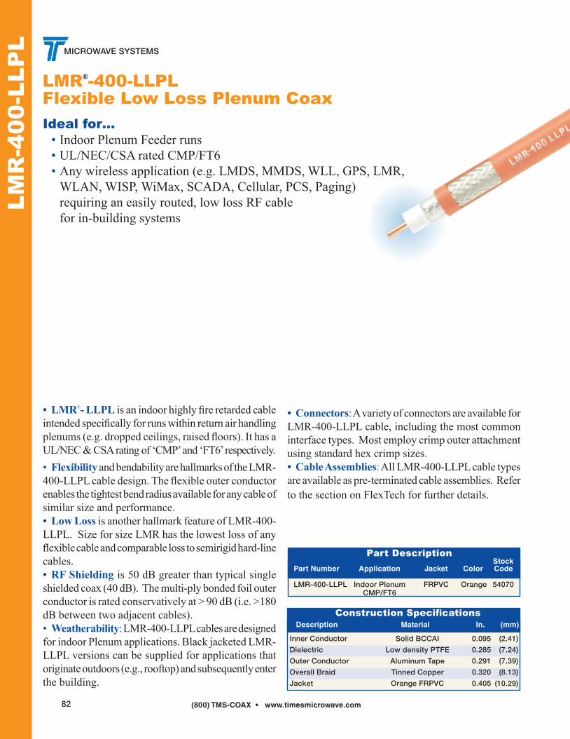
LMR®-400-LLPL Flexible Low Loss Plenum Coax
LMR
-400
-LLP
L
Part Description Stock Part Number Application Jacket Color Code LMR-400-LLPL Indoor Plenum FRPVC Orange 54070 CMP/FT6
• LMR®- LLPL is an indoor highly fire retarded cable intended specifically for runs within return air handling plenums (e.g. dropped ceilings, raised floors). It has a UL/NEC & CSA rating of ‘CMP’ and ‘FT6’ respectively.• Flexibility and bendability are hallmarks of the LMR-400-LLPL cable design. The flexible outer conductor enables the tightest bend radius available for any cable of similar size and performance.• Low Loss is another hallmark feature of LMR-400-LLPL. Size for size LMR has the lowest loss of any flexible cable and comparable loss to semirigid hard-line cables.• RF Shielding is 50 dB greater than typical single shielded coax (40 dB). The multi-ply bonded foil outer conductor is rated conservatively at > 90 dB (i.e. >180 dB between two adjacent cables). • Weatherability: LMR-400-LLPL cables are designed for indoor Plenum applications. Black jacketed LMR-LLPL versions can be supplied for applications that originate outdoors (e.g., rooftop) and subsequently enter the building.
Ideal for… • Indoor Plenum Feeder runs • UL/NEC/CSA rated CMP/FT6 • Any wireless application (e.g. LMDS, MMDS, WLL, GPS, LMR, WLAN, WISP, WiMax, SCADA, Cellular, PCS, Paging) requiring an easily routed, low loss RF cable for in-building systems
Construction Specifications Description Material In. (mm)
Inner Conductor Solid BCCAI 0.095 (2.41)
Dielectric Low density PTFE 0.285 (7.24)
Outer Conductor Aluminum Tape 0.291 (7.39)
Overall Braid Tinned Copper 0.320 (8.13)
Jacket Orange FRPVC 0.405 (10.29)
• Connectors: A variety of connectors are available for LMR-400-LLPL cable, including the most common interface types. Most employ crimp outer attachment using standard hex crimp sizes.• Cable Assemblies: All LMR-400-LLPL cable types are available as pre-terminated cable assemblies. Refer to the section on FlexTech for further details.