amazon virtual private cloud - ネットワーク管理者ガイド · amazon virtual private cloud...
TRANSCRIPT
Amazon Virtual Private Cloudネットワーク管理者ガイド
Amazon Virtual Private Cloud ネットワーク管理者ガイド
Amazon Virtual Private Cloud: ネットワーク管理者ガイドCopyright © 2018 Amazon Web Services, Inc. and/or its affiliates. All rights reserved.
Amazon's trademarks and trade dress may not be used in connection with any product or service that is not Amazon's, in any mannerthat is likely to cause confusion among customers, or in any manner that disparages or discredits Amazon. All other trademarks notowned by Amazon are the property of their respective owners, who may or may not be affiliated with, connected to, or sponsored byAmazon.
Amazon Virtual Private Cloud ネットワーク管理者ガイド
Table of Contentsようこそ ............................................................................................................................................ 1カスタマーゲートウェイ ...................................................................................................................... 2
カスタマーゲートウェイの概要 ..................................................................................................... 2担当 .................................................................................................................................. 3
VPN 接続の設定の概要 ................................................................................................................ 4ネットワーク情報 ............................................................................................................... 4
AWS VPN CloudHub と冗長なカスタマーゲートウェイ .................................................................... 5VPC への複数の VPN 接続の設定 ................................................................................................ 6Amazon でテスト済みのカスタマーゲートウェイデバイス ................................................................ 7カスタマーゲートウェイの要件 ..................................................................................................... 8インターネットとカスタマーゲートウェイ間のファイアウォールの設定 ............................................ 11
例: BGP を使用した Check Point デバイス ........................................................................................... 13カスタマーゲートウェイの概要 ................................................................................................... 13設定ファイル ............................................................................................................................ 14Check Point デバイスの設定 ....................................................................................................... 14
ステップ 1: トンネルインターフェイスを設定する ................................................................. 15ステップ 2: BGP を設定する .............................................................................................. 16ステップ 3: ネットワークオブジェクトを作成する ................................................................. 16ステップ 4: VPN コミュニティを作成し IKE と IPsec を設定する ............................................ 17ステップ 5: ファイアウォールを設定する ............................................................................. 19ステップ 6: Dead Peer Detection および TCP MSS クランプを有効にする ................................ 20
カスタマーゲートウェイ設定をテストする方法 .............................................................................. 21例: Check Point デバイス (BGP なし) .................................................................................................. 24
カスタマーゲートウェイの概要 ................................................................................................... 24設定ファイル ............................................................................................................................ 25Check Point デバイスの設定 ....................................................................................................... 25
ステップ 1: トンネルインターフェイスを設定する ................................................................. 26ステップ 2: 静的ルートを設定する ...................................................................................... 27ステップ 3: ネットワークオブジェクトを作成する ................................................................. 29ステップ 4: VPN コミュニティを作成し IKE と IPsec を設定する ............................................ 30ステップ 5: ファイアウォールを設定する ............................................................................. 31ステップ 6: Dead Peer Detection および TCP MSS クランプを有効にする ................................ 32
カスタマーゲートウェイ設定をテストする方法 .............................................................................. 33例: Cisco ASA デバイス ..................................................................................................................... 36
カスタマーゲートウェイの概要 ................................................................................................... 36設定例 ..................................................................................................................................... 37カスタマーゲートウェイ設定をテストする方法 .............................................................................. 41
例: Cisco ASA デバイスと VTI および BGP .......................................................................................... 43カスタマーゲートウェイの概要 ................................................................................................... 43設定例 ..................................................................................................................................... 44カスタマーゲートウェイ設定をテストする方法 .............................................................................. 49
例: Cisco ASA デバイスと VTI (BGP なし) ........................................................................................... 52カスタマーゲートウェイの概要 ................................................................................................... 52設定例 ..................................................................................................................................... 53カスタマーゲートウェイ設定をテストする方法 .............................................................................. 58
例: Cisco IOS デバイス ..................................................................................................................... 60カスタマーゲートウェイの概要 ................................................................................................... 61カスタマーゲートウェイの詳細と設定例 ....................................................................................... 62カスタマーゲートウェイ設定をテストする方法 .............................................................................. 68
例: Cisco IOS デバイス (BGP なし) ..................................................................................................... 71カスタマーゲートウェイの概要 ................................................................................................... 71カスタマーゲートウェイの詳細と設定例 ....................................................................................... 72カスタマーゲートウェイ設定をテストする方法 .............................................................................. 77
例: Dell SonicWALL デバイス ............................................................................................................. 80
iii
Amazon Virtual Private Cloud ネットワーク管理者ガイド
カスタマーゲートウェイの概要 ................................................................................................... 80構成ファイルの例 ...................................................................................................................... 81管理インターフェイスを使用して SonicWALL デバイスを設定する .................................................. 84カスタマーゲートウェイ設定をテストする方法 .............................................................................. 85
例: Dell SonicWALL デバイス (BGP なし) ............................................................................................ 87カスタマーゲートウェイの概要 ................................................................................................... 87構成ファイルの例 ...................................................................................................................... 88管理インターフェイスを使用して SonicWALL デバイスを設定する .................................................. 91カスタマーゲートウェイ設定をテストする方法 .............................................................................. 93
例: Fortinet Fortigate デバイス ............................................................................................................ 95カスタマーゲートウェイの概要 ................................................................................................... 96カスタマーゲートウェイの詳細と設定例 ....................................................................................... 96カスタマーゲートウェイ設定をテストする方法 ............................................................................ 104
例: Juniper J-Series JunOS デバイス ................................................................................................. 106カスタマーゲートウェイの概要 ................................................................................................. 107カスタマーゲートウェイの詳細と設定例 ..................................................................................... 108カスタマーゲートウェイ設定をテストする方法 ............................................................................ 114
例: Juniper SRX JunOS デバイス ...................................................................................................... 116カスタマーゲートウェイの概要 ................................................................................................. 117カスタマーゲートウェイの詳細と設定例 ..................................................................................... 118カスタマーゲートウェイ設定をテストする方法 ............................................................................ 124
例: Juniper ScreenOS デバイス ......................................................................................................... 126カスタマーゲートウェイの概要 ................................................................................................. 127カスタマーゲートウェイの詳細と設定例 ..................................................................................... 128カスタマーゲートウェイ設定をテストする方法 ............................................................................ 133
例: Netgate PfSense デバイス (BGP なし) .......................................................................................... 135カスタマーゲートウェイの概要 ................................................................................................. 135設定例 ................................................................................................................................... 136カスタマーゲートウェイ設定をテストする方法 ............................................................................ 139
例: パロアルトネットワークスのデバイス ........................................................................................... 141カスタマーゲートウェイの概要 ................................................................................................. 142カスタマーゲートウェイの詳細と設定例 ..................................................................................... 142カスタマーゲートウェイ設定をテストする方法 ............................................................................ 149
例: Yamaha 製デバイス ................................................................................................................... 151カスタマーゲートウェイの概要 ................................................................................................. 152カスタマーゲートウェイの詳細と設定例 ..................................................................................... 152カスタマーゲートウェイ設定をテストする方法 ............................................................................ 158
例: BGP を使用した一般的なカスタマーゲートウェイ ........................................................................... 160カスタマーゲートウェイの概要 ................................................................................................. 161カスタマーゲートウェイの詳細と設定例 ..................................................................................... 161カスタマーゲートウェイ設定をテストする方法 ............................................................................ 166
例: 一般的なカスタマーゲートウェイ (BGP なし) ................................................................................. 168カスタマーゲートウェイの概要 ................................................................................................. 169カスタマーゲートウェイの詳細と設定例 ..................................................................................... 169カスタマーゲートウェイ設定をテストする方法 ............................................................................ 174
トラブルシューティング ................................................................................................................... 176Cisco ASA カスタマーゲートウェイの接続 ................................................................................. 176
IKE ............................................................................................................................... 176IPsec ............................................................................................................................. 177ルーティング .................................................................................................................. 178
Cisco IOS カスタマーゲートウェイの接続 .................................................................................. 179IKE ............................................................................................................................... 179IPsec ............................................................................................................................. 180トンネル ........................................................................................................................ 182BGP .............................................................................................................................. 183仮想プライベートゲートウェイのアタッチ .......................................................................... 183
Cisco IOS カスタマーゲートウェイの接続 (BGP なし) .................................................................. 184
iv
Amazon Virtual Private Cloud ネットワーク管理者ガイド
IKE ............................................................................................................................... 184IPsec ............................................................................................................................. 184トンネル ........................................................................................................................ 186仮想プライベートゲートウェイのアタッチ .......................................................................... 188
Juniper JunOS カスタマーゲートウェイの接続 ............................................................................ 188IKE ............................................................................................................................... 188IPsec ............................................................................................................................. 189トンネル ........................................................................................................................ 189BGP .............................................................................................................................. 190仮想プライベートゲートウェイのアタッチ .......................................................................... 191
Juniper ScreenOS カスタマーゲートウェイの接続 ....................................................................... 191IKE と IPsec .................................................................................................................. 191トンネル ........................................................................................................................ 192BGP .............................................................................................................................. 193仮想プライベートゲートウェイのアタッチ .......................................................................... 194
Yamaha 製カスタマーゲートウェイの接続 .................................................................................. 194IKE ............................................................................................................................... 194IPsec ............................................................................................................................. 195トンネル ........................................................................................................................ 196BGP .............................................................................................................................. 196仮想プライベートゲートウェイのアタッチ .......................................................................... 197
一般的なデバイスのカスタマーゲートウェイの接続 ...................................................................... 197一般的なデバイスのカスタマーゲートウェイ接続 (BGP なし) ........................................................ 200
Windows Server 2008 R2 のカスタマーゲートウェイとしての設定 ......................................................... 203Windows Server の設定 ........................................................................................................... 203ステップ 1: VPN 接続を作成し、VPC を設定する ....................................................................... 204ステップ 2: VPN 接続の設定ファイルをダウンロードする ............................................................. 205ステップ 3: Windows Server を設定する .................................................................................... 206ステップ 4: VPN トンネルを設定する ........................................................................................ 209
オプション 1: netsh スクリプトを実行する ......................................................................... 209オプション 2: Windows Server ユーザーインターフェイスを使用する ..................................... 209
ステップ 5: 停止しているゲートウェイを検出する ....................................................................... 215ステップ 6: VPN 接続をテストする ........................................................................................... 215
Windows Server 2012 R2 のカスタマーゲートウェイとしての設定 ......................................................... 217Windows Server の設定 ........................................................................................................... 217ステップ 1: VPN 接続を作成し、VPC を設定する ....................................................................... 218ステップ 2: VPN 接続の設定ファイルをダウンロードする ............................................................. 219ステップ 3: Windows Server を設定する .................................................................................... 220ステップ 4: VPN トンネルを設定する ........................................................................................ 221
オプション 1: netsh スクリプトを実行する ......................................................................... 222オプション 2: Windows Server ユーザーインターフェイスを使用する ..................................... 2222.4: Windows ファイアウォールを設定する ......................................................................... 226
ステップ 5: 停止しているゲートウェイを検出する ....................................................................... 227ステップ 6: VPN 接続をテストする ........................................................................................... 228
ドキュメント履歴 ............................................................................................................................ 230
v
Amazon Virtual Private Cloud ネットワーク管理者ガイド
ようこそAmazon VPC ネットワーク管理者ガイドへようこそ。このガイドは、Virtual Private Cloud (VPC) で AWSマネージド IPsec VPN 接続を使用する予定のお客様向けに作成されています。このガイドのトピックは、VPN 接続のユーザー側のデバイスであるカスタマーゲートウェイを設定する場合に役立ちます。
VPN 接続を使用すると、VPC と IT インフラストラクチャをつなぐことができ、VPC の EC2 インスタンスに対して (インフラストラクチャ内で動作しているインスタンスと同じように) 既存のセキュリティおよび管理ポリシーを拡張することができます。
詳細については、次のトピックを参照してください。
• カスタマーゲートウェイ (p. 2)• 例: ボーダーゲートウェイプロトコルを使用した Check Point デバイス (p. 13)• 例: ボーダーゲートウェイプロトコルを使用しない Check Point デバイス (p. 24)• 例: Cisco ASA デバイス (p. 36)• 例: Cisco IOS デバイス (p. 60)• 例: ボーダーゲートウェイプロトコルを使用しない Cisco IOS デバイス (p. 71)• 例: Cisco ASA デバイスと仮想トンネルインターフェイス、およびボーダーゲートウェイプロトコ
ル (p. 43)• 例: Cisco ASA デバイスと仮想トンネルインターフェイス (ボーダーゲートウェイプロトコルな
し) (p. 52)• 例: ボーダーゲートウェイプロトコルを使用しない Dell SonicWALL SonicOS デバイス (p. 87)• 例: Dell SonicWALL デバイス (p. 80)• 例: Juniper J-Series JunOS デバイス (p. 106)• 例: Juniper SRX JunOS デバイス (p. 116)• 例: Juniper ScreenOS デバイス (p. 126)• 例: ボーダーゲートウェイプロトコルを使用しない Netgate PfSense デバイス (p. 135)• 例: パロアルトネットワークスのデバイス (p. 141)• 例: Yamaha 製デバイス (p. 151)• 例: ボーダーゲートウェイプロトコルを使用した一般的なカスタマーゲートウェイ (p. 160)• 例: ボーダーゲートウェイプロトコルを使用しない一般的なカスタマーゲートウェイ (p. 168)• Windows Server 2008 R2 のカスタマーゲートウェイとしての設定 (p. 203)• Windows Server 2012 R2 のカスタマーゲートウェイとしての設定 (p. 217)
1
Amazon Virtual Private Cloud ネットワーク管理者ガイドカスタマーゲートウェイの概要
カスタマーゲートウェイトピック
• カスタマーゲートウェイの概要 (p. 2)• VPN 接続の設定の概要 (p. 4)• AWS VPN CloudHub と冗長なカスタマーゲートウェイ (p. 5)• VPC への複数の VPN 接続の設定 (p. 6)• Amazon でテスト済みのカスタマーゲートウェイデバイス (p. 7)• カスタマーゲートウェイの要件 (p. 8)• インターネットとカスタマーゲートウェイ間のファイアウォールの設定 (p. 11)
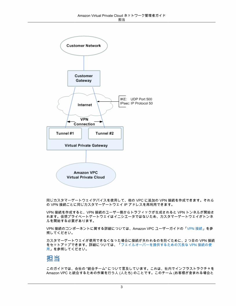
カスタマーゲートウェイの概要Amazon VPC VPN 接続では、データセンター (またはネットワーク) を Amazon VPC 仮想プライベートクラウド (VPC) にリンクします。カスタマーゲートウェイは、その接続の作業者側のアンカーです。物理的アプライアンスにすることも、ソフトウェア的アプライアンスにすることもできます。VPN 接続の AWS側のアンカーは、仮想プライベートゲートウェイと呼ばれます。
次の図は、ネットワーク、カスタマーゲートウェイ、仮想プライベートゲートウェイへの VPN 接続、および VPC を示しています。カスタマーゲートウェイと仮想プライベートゲートウェイ間には 2 つの線があります。これは、VPN 接続が Amazon VPC サービスの可用性を高めるために、2 つのトンネルで構成されるためです。AWS でデバイス障害が発生した場合、VPN 接続は自動的に 2 番目のトンネルにフェールオーバーして、アクセスが中断されないようにします。ときどき、AWS は、仮想プライベートゲートウェイで定期メンテナンスを実行します。これにより、VPN 接続の 2 つのトンネルの 1 つが短時間無効になる場合があります。このメンテナンスの実行中、VPN 接続は自動的に 2 番目のトンネルにフェイルオーバーします。したがって、カスタマーゲートウェイを設定するときは、両方のトンネルを設定することが重要です。
2
Amazon Virtual Private Cloud ネットワーク管理者ガイド担当
同じカスタマーゲートウェイデバイスを使用して、他の VPC に追加の VPN 接続を作成できます。それらの VPN 接続ごとに同じカスタマーゲートウェイ IP アドレスを再利用できます。
VPN 接続を作成すると、VPN 接続のユーザー側からトラフィックが生成されると VPN トンネルが開始されます。仮想プライベートゲートウェイはイニシエータではないため、カスタマーゲートウェイがトンネルを開始する必要があります。
VPN 接続のコンポーネントに関する詳細については、Amazon VPC ユーザーガイドの「VPN 接続」を参照してください。
カスタマーゲートウェイが使用できなくなった場合に接続が失われるのを防ぐために、2 つ目の VPN 接続をセットアップできます。詳細については、「フェイルオーバーを提供するための冗長な VPN 接続の使用」を参照してください。
担当このガイドでは、会社の "統合チーム" について言及しています。これは、社内でインフラストラクチャをAmazon VPC と統合するための作業を行う人 (人たち) のことです。このチーム (お客様が含まれる場合と
3
Amazon Virtual Private Cloud ネットワーク管理者ガイドVPN 接続の設定の概要
そうでない場合があります) は、AWS マネジメントコンソールを使用して VPN 接続を作成し、お客様がカスタマーゲートウェイを設定するために必要な情報を取得します。会社が各タスクのために個別のチームを持っている場合があるかもしれません (AWS マネジメントコンソールを使用する統合チームと、ネットワークデバイスにアクセスでき、カスタマーゲートウェイを設定する、別のネットワークエンジニアリンググループ)。このガイドでは、読者がネットワークエンジニアリンググループの一員であり、会社の統合チームから情報を受け取って、カスタマーゲートウェイデバイスを設定できる人物であると想定しています。
VPN 接続の設定の概要AWS で VPN 接続をセットアップするプロセスについては、「Amazon VPC ユーザーガイド」で説明されています。全体のプロセスのタスクの 1 つに、カスタマーゲートウェイの設定があります。VPN 接続を作成するため、AWS ではカスタマーゲートウェイに関する情報が必要であり、お客様はカスタマーゲートウェイデバイス自体を設定する必要があります。
VPN 接続を設定するには、以下の一般的な手順に従います。
1. カスタマーゲートウェイとして動作するアプライアンスを指定します。詳細については、「Amazonでテスト済みのカスタマーゲートウェイデバイス (p. 7)」および「カスタマーゲートウェイの要件 (p. 8)」を参照してください。
2. 必要な ネットワーク情報 (p. 4) を取得し、AWS で VPN 接続を作成するチームに、この情報を提供します。
3. AWS で VPN 接続を作成し、カスタマーゲートウェイの設定ファイルを取得します。詳細については、Amazon VPC ユーザーガイド の「AWS VPN 接続のセットアップ」を参照してください。
4. 設定ファイルの情報を使用して、カスタマーゲートウェイを設定します。このガイドに例を用意しています。
5. VPN 接続のユーザー側からトラフィックを生成し、VPN トンネルを起動します。
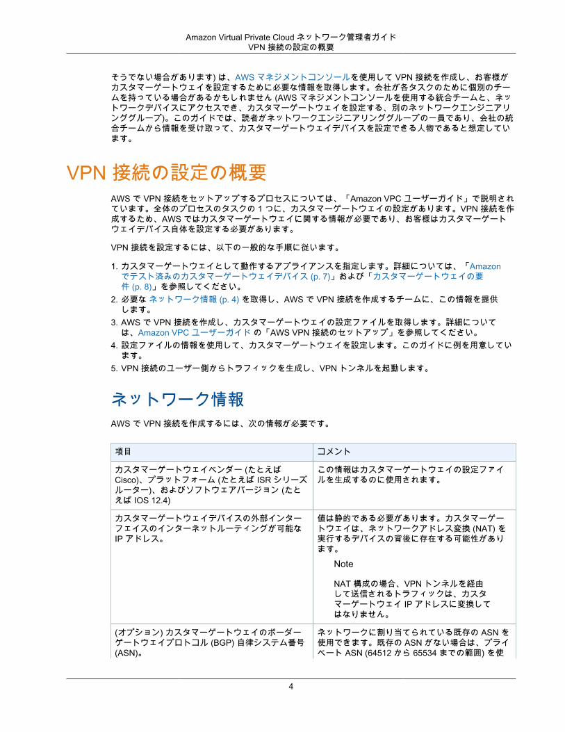
ネットワーク情報AWS で VPN 接続を作成するには、次の情報が必要です。
項目 コメント
カスタマーゲートウェイベンダー (たとえばCisco)、プラットフォーム (たとえば ISR シリーズルーター)、およびソフトウェアバージョン (たとえば IOS 12.4)
この情報はカスタマーゲートウェイの設定ファイルを生成するのに使用されます。
カスタマーゲートウェイデバイスの外部インターフェイスのインターネットルーティングが可能なIP アドレス。
値は静的である必要があります。カスタマーゲートウェイは、ネットワークアドレス変換 (NAT) を実行するデバイスの背後に存在する可能性があります。
Note
NAT 構成の場合、VPN トンネルを経由して送信されるトラフィックは、カスタマーゲートウェイ IP アドレスに変換してはなりません。
(オプション) カスタマーゲートウェイのボーダーゲートウェイプロトコル (BGP) 自律システム番号(ASN)。
ネットワークに割り当てられている既存の ASN を使用できます。既存の ASN がない場合は、プライベート ASN (64512 から 65534 までの範囲) を使
4
Amazon Virtual Private Cloud ネットワーク管理者ガイドAWS VPN CloudHub と冗長なカスタマーゲートウェイ
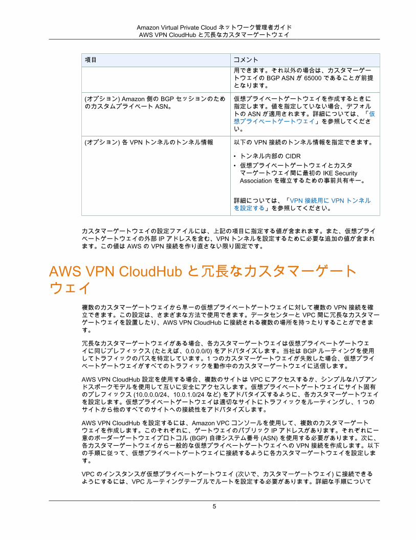
項目 コメント用できます。それ以外の場合は、カスタマーゲートウェイの BGP ASN が 65000 であることが前提となります。
(オプション) Amazon 側の BGP セッションのためのカスタムプライベート ASN。
仮想プライベートゲートウェイを作成するときに指定します。値を指定していない場合、デフォルトの ASN が適用されます。詳細については、「仮想プライベートゲートウェイ」を参照してください。
(オプション) 各 VPN トンネルのトンネル情報 以下の VPN 接続のトンネル情報を指定できます。
• トンネル内部の CIDR• 仮想プライベートゲートウェイとカスタ
マーゲートウェイ間に最初の IKE SecurityAssociation を確立するための事前共有キー。
詳細については、「VPN 接続用に VPN トンネルを設定する」を参照してください。
カスタマーゲートウェイの設定ファイルには、上記の項目に指定する値が含まれます。また、仮想プライベートゲートウェイの外部 IP アドレスを含む、VPN トンネルを設定するために必要な追加の値が含まれます。この値は AWS の VPN 接続を作り直さない限り固定です。
AWS VPN CloudHub と冗長なカスタマーゲートウェイ
複数のカスタマーゲートウェイから単一の仮想プライベートゲートウェイに対して複数の VPN 接続を確立できます。この設定は、さまざまな方法で使用できます。データセンターと VPC 間に冗長なカスタマーゲートウェイを設置したり、AWS VPN CloudHub に接続される複数の場所を持ったりすることができます。
冗長なカスタマーゲートウェイがある場合、各カスタマーゲートウェイは仮想プライベートゲートウェイに同じプレフィックス (たとえば、0.0.0.0/0) をアドバタイズします。当社は BGP ルーティングを使用してトラフィックのパスを特定しています。1 つのカスタマーゲートウェイが失敗した場合、仮想プライベートゲートウェイがすべてのトラフィックを動作中のカスタマーゲートウェイに送信します。
AWS VPN CloudHub 設定を使用する場合、複数のサイトは VPC にアクセスするか、シンプルなハブアンドスポークモデルを使用して互いに安全にアクセスします。仮想プライベートゲートウェイにサイト固有のプレフィックス (10.0.0.0/24、10.0.1.0/24 など) をアドバタイズするように、各カスタマーゲートウェイを設定します。仮想プライベートゲートウェイは適切なサイトにトラフィックをルーティングし、1 つのサイトから他のすべてのサイトへの接続性をアドバタイズします。
AWS VPN CloudHub を設定するには、Amazon VPC コンソールを使用して、複数のカスタマーゲートウェイを作成します。このそれぞれに、ゲートウェイのパブリック IP アドレスがあります。それぞれに一意のボーダーゲートウェイプロトコル (BGP) 自律システム番号 (ASN) を使用する必要があります。次に、各カスタマーゲートウェイから一般的な仮想プライベートゲートウェイへの VPN 接続を作成します。以下の手順に従って、仮想プライベートゲートウェイに接続するように各カスタマーゲートウェイを設定します。
VPC のインスタンスが仮想プライベートゲートウェイ (次いで、カスタマーゲートウェイ) に接続できるようにするには、VPC ルーティングテーブルでルートを設定する必要があります。詳細な手順について
5
Amazon Virtual Private Cloud ネットワーク管理者ガイドVPC への複数の VPN 接続の設定
は、Amazon VPC ユーザーガイドの「VPN 接続」を参照してください。AWS VPN CloudHub では、VPCルーティングテーブルで集約ルート (たとえば、10.0.0.0/16) を設定したり、カスタマーゲートウェイと仮想プライベートゲートウェイ間でより具体的なプレフィックスを使用したりすることができます。
VPC への複数の VPN 接続の設定VPC 用に最大で 10 個の VPN 接続を作成できます。複数のリモートオフィスを同じ VPC にリンクするために、複数の VPN 接続を使用できます。例えば、ロサンゼルス、シカゴ、ニューヨーク、およびマイアミにオフィスがある場合は、それぞれのオフィスを VPC に接続することができます。また、1 つの場所からの冗長なカスタマーゲートウェイを確立するためにも、複数の VPN 接続を使用できます。
Note
10 個を超える VPN 接続が必要な場合は、Amazon VPC 制限の引き上げをリクエストするフォームに入力して、制限の引き上げをリクエストします。
複数の VPN 接続を作成すると、仮想プライベートゲートウェイは静的に割り当てられたルートを使用するか、BGP ルートアドバタイズメントを使用して、適切な VPN 接続にネットワークトラフィックを送信します。どちらを使用するかは、VPN 接続がどのように設定されているかによって決まります。仮想プライベートゲートウェイに同一のルートが存在している場合は、BGP でアドバタイズされるルートよりも、静的に割り当てられたルートの方が適しています。
複数の地理的ロケーションにカスタマーゲートウェイがある場合、各カスタマーゲートウェイは、ロケーションに固有の一意な IP 範囲のセットをアドバタイズする必要があります。1 つの場所に冗長なカスタマーゲートウェイを確立した場合は、両方のゲートウェイが同じ IP 範囲をアドバタイズする必要があります。
仮想プライベートゲートウェイは、すべてのカスタマーゲートウェイからルーティング情報を受け取り、BGP の最良パス選択アルゴリズムを使用して望ましいパスのセットを計算します。このアルゴリズムのルールは、VPC に適用される場合、次のようになります。
1. 最も具体的な IP プレフィックスが優先されます (たとえば、10.0.0.0/24 は 10.0.0.0/16 よりも優先されます)。詳細については、Amazon VPC ユーザーガイド の「ルーティングの優先度」を参照してください。
2. プレフィックスが同じである場合は、静的に設定された VPN 接続があれば、それが優先されます。各 VPN 接続が BGP を使用しているプレフィックスのマッチングでは、AS PATH が比較され、最短の AS PATH を持っているプレフィックスが優先されます。また、パスの優先度が低くなるように、AS_PATH を前に追加できます。
3. AS PATH の長さが同じ場合は、パスのオリジンが比較されます。不明なオリジンのプレフィックスよりも Exterior Gateway Protocol (EGP) オリジンのプレフィックスが優先され、それよりも InteriorGateway Protocol (IGP) オリジンのプレフィックスが優先されます。
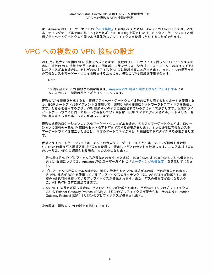
次の図は、複数の VPN の設定を示しています。
6
Amazon Virtual Private Cloud ネットワーク管理者ガイドAmazon でテスト済みのカスタマーゲートウェイデバイス
Amazon でテスト済みのカスタマーゲートウェイデバイス
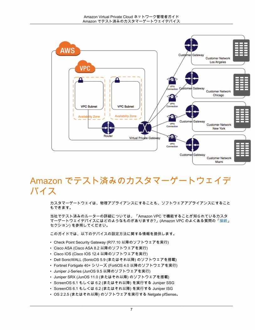
カスタマーゲートウェイは、物理アプライアンスにすることも、ソフトウェアアプライアンスにすることもできます。
当社でテスト済みのルーターの詳細については、「Amazon VPC で機能することが知られているカスタマーゲートウェイデバイスにはどのようなものがありますか?」(Amazon VPC のよくある質問の「接続」セクション) を参照してください。
このガイドでは、以下のデバイスの設定方法に関する情報を提供します。
• Check Point Security Gateway (R77.10 以降のソフトウェアを実行)• Cisco ASA (Cisco ASA 8.2 以降のソフトウェアを実行)• Cisco IOS (Cisco IOS 12.4 以降のソフトウェアを実行)• Dell SonicWALL (SonicOS 5.9 (またはそれ以降) のソフトウェアを搭載)• Fortinet Fortigate 40+ シリーズ (FortiOS 4.0 以降のソフトウェアを実行)• Juniper J-Series (JunOS 9.5 以降のソフトウェアを実行)• Juniper SRX (JunOS 11.0 (またはそれ以降) のソフトウェアを搭載)• ScreenOS 6.1 もしくは 6.2 (またはそれ以降) を実行する Juniper SSG• ScreenOS 6.1 もしくは 6.2 (またはそれ以降) を実行する Juniper ISG• OS 2.2.5 (またはそれ以降) のソフトウェアを実行する Netgate pfSense。
7
Amazon Virtual Private Cloud ネットワーク管理者ガイドカスタマーゲートウェイの要件
• Palo Alto Networks PANOS 4.1.2 (またはそれ以降) ソフトウェア• Yamaha RT107e、RTX1200、RTX1210、RTX1500、RTX3000、および SRT100 ルーター• Microsoft Windows Server 2008 R2 以降のソフトウェア• Microsoft Windows Server 2012 R2 以降のソフトウェア• 静的にルーティングされる VPN 接続用の Zyxel Zywall シリーズ 4.20 (またはそれ以降) ソフトウェア、
または動的にルーティングされる VPN 接続用の 4.30 (またはそれ以降) ソフトウェア
これらのデバイスのいずれかを持っているものの、このガイドで示されているのとは異なる方法で IPsec用に設定されている場合は、自分の特定のニーズに合わせて推奨設定を自由に変更してかまいません。
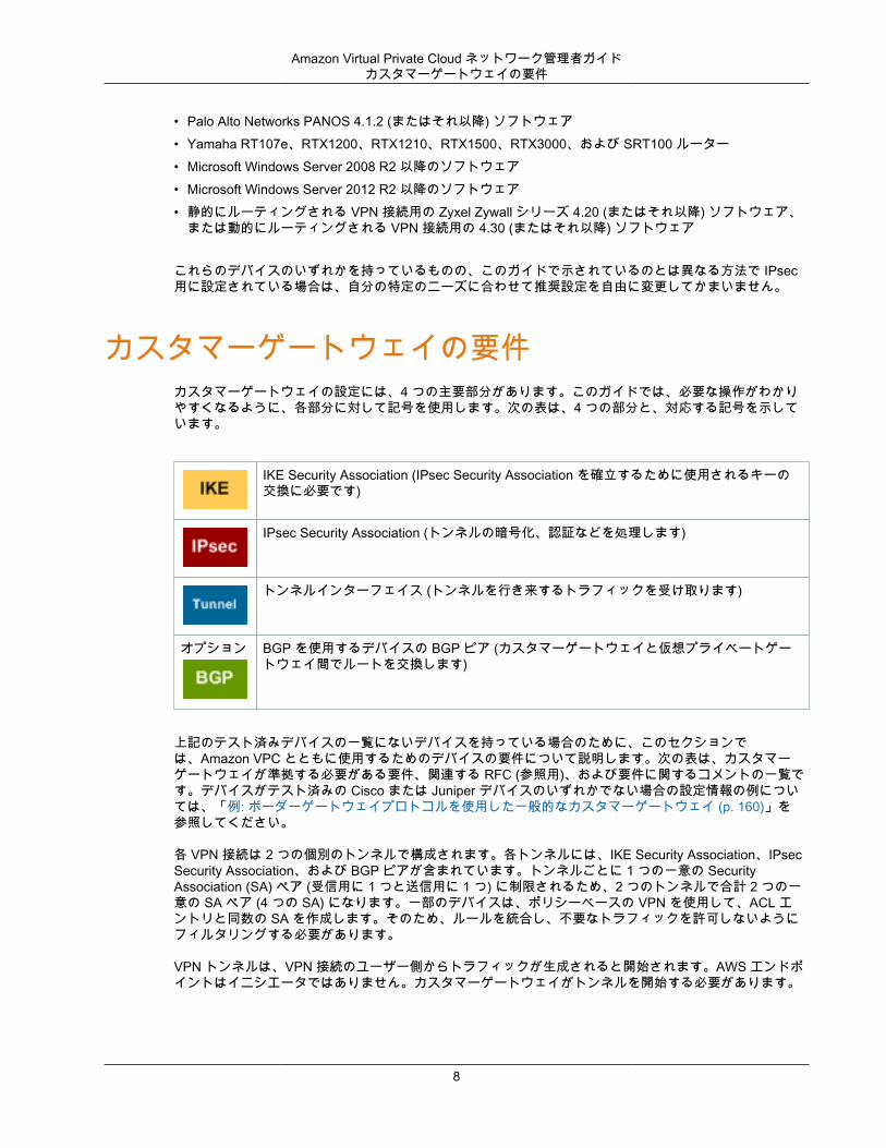
カスタマーゲートウェイの要件カスタマーゲートウェイの設定には、4 つの主要部分があります。このガイドでは、必要な操作がわかりやすくなるように、各部分に対して記号を使用します。次の表は、4 つの部分と、対応する記号を示しています。
IKE Security Association (IPsec Security Association を確立するために使用されるキーの交換に必要です)
IPsec Security Association (トンネルの暗号化、認証などを処理します)
トンネルインターフェイス (トンネルを行き来するトラフィックを受け取ります)
オプション BGP を使用するデバイスの BGP ピア (カスタマーゲートウェイと仮想プライベートゲートウェイ間でルートを交換します)
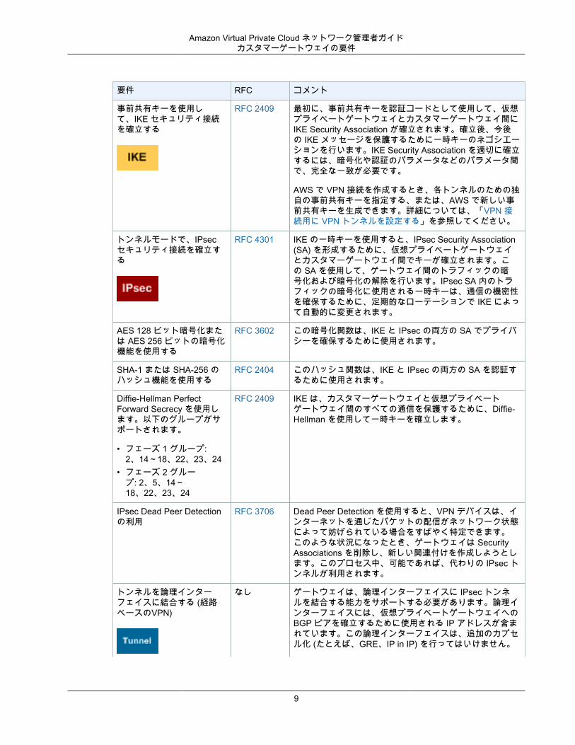
上記のテスト済みデバイスの一覧にないデバイスを持っている場合のために、このセクションでは、Amazon VPC とともに使用するためのデバイスの要件について説明します。次の表は、カスタマーゲートウェイが準拠する必要がある要件、関連する RFC (参照用)、および要件に関するコメントの一覧です。デバイスがテスト済みの Cisco または Juniper デバイスのいずれかでない場合の設定情報の例については、「例: ボーダーゲートウェイプロトコルを使用した一般的なカスタマーゲートウェイ (p. 160)」を参照してください。
各 VPN 接続は 2 つの個別のトンネルで構成されます。各トンネルには、IKE Security Association、IPsecSecurity Association、および BGP ピアが含まれています。トンネルごとに 1 つの一意の SecurityAssociation (SA) ペア (受信用に 1 つと送信用に 1 つ) に制限されるため、2 つのトンネルで合計 2 つの一意の SA ペア (4 つの SA) になります。一部のデバイスは、ポリシーベースの VPN を使用して、ACL エントリと同数の SA を作成します。そのため、ルールを統合し、不要なトラフィックを許可しないようにフィルタリングする必要があります。
VPN トンネルは、VPN 接続のユーザー側からトラフィックが生成されると開始されます。AWS エンドポイントはイニシエータではありません。カスタマーゲートウェイがトンネルを開始する必要があります。
8
Amazon Virtual Private Cloud ネットワーク管理者ガイドカスタマーゲートウェイの要件
要件 RFC コメント
事前共有キーを使用して、IKE セキュリティ接続を確立する
RFC 2409 最初に、事前共有キーを認証コードとして使用して、仮想プライベートゲートウェイとカスタマーゲートウェイ間にIKE Security Association が確立されます。確立後、今後の IKE メッセージを保護するために一時キーのネゴシエーションを行います。IKE Security Association を適切に確立するには、暗号化や認証のパラメータなどのパラメータ間で、完全な一致が必要です。
AWS で VPN 接続を作成するとき、各トンネルのための独自の事前共有キーを指定する、または、AWS で新しい事前共有キーを生成できます。詳細については、「VPN 接続用に VPN トンネルを設定する」を参照してください。
トンネルモードで、IPsecセキュリティ接続を確立する
RFC 4301 IKE の一時キーを使用すると、IPsec Security Association(SA) を形成するために、仮想プライベートゲートウェイとカスタマーゲートウェイ間でキーが確立されます。この SA を使用して、ゲートウェイ間のトラフィックの暗号化および暗号化の解除を行います。IPsec SA 内のトラフィックの暗号化に使用される一時キーは、通信の機密性を確保するために、定期的なローテーションで IKE によって自動的に変更されます。
AES 128 ビット暗号化または AES 256 ビットの暗号化機能を使用する
RFC 3602 この暗号化関数は、IKE と IPsec の両方の SA でプライバシーを確保するために使用されます。
SHA-1 または SHA-256 のハッシュ機能を使用する
RFC 2404 このハッシュ関数は、IKE と IPsec の両方の SA を認証するために使用されます。
Diffie-Hellman PerfectForward Secrecy を使用します。以下のグループがサポートされます。
• フェーズ 1 グループ:2、14~18、22、23、24
• フェーズ 2 グループ: 2、5、14~18、22、23、24
RFC 2409 IKE は、カスタマーゲートウェイと仮想プライベートゲートウェイ間のすべての通信を保護するために、Diffie-Hellman を使用して一時キーを確立します。
IPsec Dead Peer Detectionの利用
RFC 3706 Dead Peer Detection を使用すると、VPN デバイスは、インターネットを通じたパケットの配信がネットワーク状態によって妨げられている場合をすばやく特定できます。このような状況になったとき、ゲートウェイは SecurityAssociations を削除し、新しい関連付けを作成しようとします。このプロセス中、可能であれば、代わりの IPsec トンネルが利用されます。
トンネルを論理インターフェイスに結合する (経路ベースのVPN)
なし ゲートウェイは、論理インターフェイスに IPsec トンネルを結合する能力をサポートする必要があります。論理インターフェイスには、仮想プライベートゲートウェイへのBGP ピアを確立するために使用される IP アドレスが含まれています。この論理インターフェイスは、追加のカプセル化 (たとえば、GRE、IP in IP) を行ってはいけません。
9
Amazon Virtual Private Cloud ネットワーク管理者ガイドカスタマーゲートウェイの要件
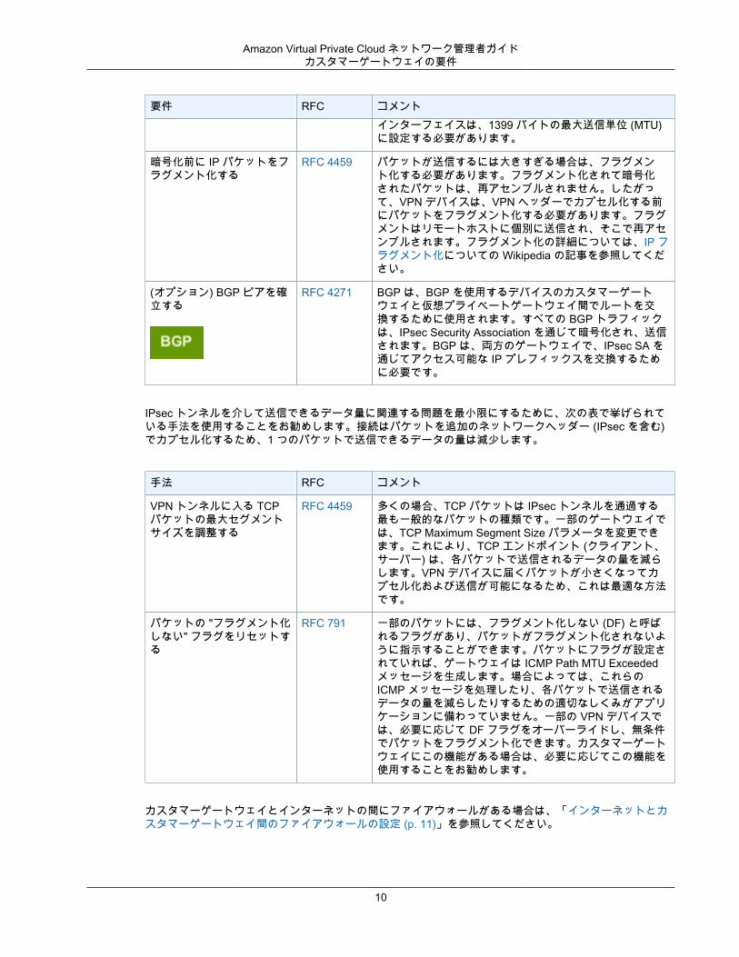
要件 RFC コメントインターフェイスは、1399 バイトの最大送信単位 (MTU)に設定する必要があります。
暗号化前に IP パケットをフラグメント化する
RFC 4459 パケットが送信するには大きすぎる場合は、フラグメント化する必要があります。フラグメント化されて暗号化されたパケットは、再アセンブルされません。したがって、VPN デバイスは、VPN ヘッダーでカプセル化する前にパケットをフラグメント化する必要があります。フラグメントはリモートホストに個別に送信され、そこで再アセンブルされます。フラグメント化の詳細については、IP フラグメント化についての Wikipedia の記事を参照してください。
(オプション) BGP ピアを確立する
RFC 4271 BGP は、BGP を使用するデバイスのカスタマーゲートウェイと仮想プライベートゲートウェイ間でルートを交換するために使用されます。すべての BGP トラフィックは、IPsec Security Association を通じて暗号化され、送信されます。BGP は、両方のゲートウェイで、IPsec SA を通じてアクセス可能な IP プレフィックスを交換するために必要です。
IPsec トンネルを介して送信できるデータ量に関連する問題を最小限にするために、次の表で挙げられている手法を使用することをお勧めします。接続はパケットを追加のネットワークヘッダー (IPsec を含む)でカプセル化するため、1 つのパケットで送信できるデータの量は減少します。
手法 RFC コメント
VPN トンネルに入る TCPパケットの最大セグメントサイズを調整する
RFC 4459 多くの場合、TCP パケットは IPsec トンネルを通過する最も一般的なパケットの種類です。一部のゲートウェイでは、TCP Maximum Segment Size パラメータを変更できます。これにより、TCP エンドポイント (クライアント、サーバー) は、各パケットで送信されるデータの量を減らします。VPN デバイスに届くパケットが小さくなってカプセル化および送信が可能になるため、これは最適な方法です。
パケットの "フラグメント化しない" フラグをリセットする
RFC 791 一部のパケットには、フラグメント化しない (DF) と呼ばれるフラグがあり、パケットがフラグメント化されないように指示することができます。パケットにフラグが設定されていれば、ゲートウェイは ICMP Path MTU Exceededメッセージを生成します。場合によっては、これらのICMP メッセージを処理したり、各パケットで送信されるデータの量を減らしたりするための適切なしくみがアプリケーションに備わっていません。一部の VPN デバイスでは、必要に応じて DF フラグをオーバーライドし、無条件でパケットをフラグメント化できます。カスタマーゲートウェイにこの機能がある場合は、必要に応じてこの機能を使用することをお勧めします。
カスタマーゲートウェイとインターネットの間にファイアウォールがある場合は、「インターネットとカスタマーゲートウェイ間のファイアウォールの設定 (p. 11)」を参照してください。
10
Amazon Virtual Private Cloud ネットワーク管理者ガイドインターネットとカスタマーゲートウェイ間のファイアウォールの設定
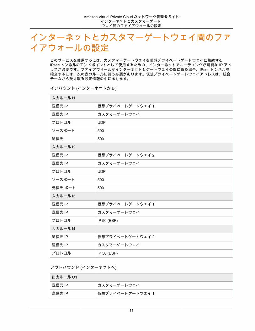
インターネットとカスタマーゲートウェイ間のファイアウォールの設定
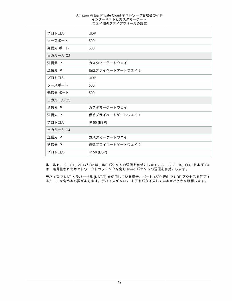
このサービスを使用するには、カスタマーゲートウェイを仮想プライベートゲートウェイに接続するIPsec トンネルのエンドポイントとして使用するための、インターネットでルーティングが可能な IP アドレスが必要です。ファイアウォールがインターネットとゲートウェイの間にある場合、IPsec トンネルを確立するには、次の表のルールに従う必要があります。仮想プライベートゲートウェイアドレスは、統合チームから受け取る設定情報の中にあります。
インバウンド (インターネットから)
入力ルール I1
送信元 IP 仮想プライベートゲートウェイ 1
送信先 IP カスタマーゲートウェイ
プロトコル UDP
ソースポート 500
送信先 500
入力ルール I2
送信元 IP 仮想プライベートゲートウェイ 2
送信先 IP カスタマーゲートウェイ
プロトコル UDP
ソースポート 500
発信先 ポート 500
入力ルール I3
送信元 IP 仮想プライベートゲートウェイ 1
送信先 IP カスタマーゲートウェイ
プロトコル IP 50 (ESP)
入力ルール I4
送信元 IP 仮想プライベートゲートウェイ 2
送信先 IP カスタマーゲートウェイ
プロトコル IP 50 (ESP)
アウトバウンド (インターネットへ)
出力ルール O1
送信元 IP カスタマーゲートウェイ
送信先 IP 仮想プライベートゲートウェイ 1
11
Amazon Virtual Private Cloud ネットワーク管理者ガイドインターネットとカスタマーゲートウェイ間のファイアウォールの設定
プロトコル UDP
ソースポート 500
発信先 ポート 500
出力ルール O2
送信元 IP カスタマーゲートウェイ
送信先 IP 仮想プライベートゲートウェイ 2
プロトコル UDP
ソースポート 500
発信先 ポート 500
出力ルール O3
送信元 IP カスタマーゲートウェイ
送信先 IP 仮想プライベートゲートウェイ 1
プロトコル IP 50 (ESP)
出力ルール O4
送信元 IP カスタマーゲートウェイ
送信先 IP 仮想プライベートゲートウェイ 2
プロトコル IP 50 (ESP)
ルール I1、I2、O1、および O2 は、IKE パケットの送信を有効にします。ルール I3、I4、O3、および O4は、暗号化されたネットワークトラフィックを含む IPsec パケットの送信を有効にします。
デバイスで NAT トラバーサル (NAT-T) を使用している場合、ポート 4500 経由で UDP アクセスを許可するルールを含める必要があります。デバイスが NAT-T をアドバタイズしているかどうかを確認します。
12
Amazon Virtual Private Cloud ネットワーク管理者ガイドカスタマーゲートウェイの概要
例: ボーダーゲートウェイプロトコルを使用した Check Point デバイス
このセクションには、カスタマーゲートウェイが R77.10 以上を実行し Gaia オペレーティングシステムを使用する Check Point Security Gateway デバイスである場合に、統合チームから提供される設定情報例が掲載されています。
トピック• カスタマーゲートウェイの概要 (p. 13)• 設定ファイル (p. 14)• Check Point デバイスの設定 (p. 14)• カスタマーゲートウェイ設定をテストする方法 (p. 21)
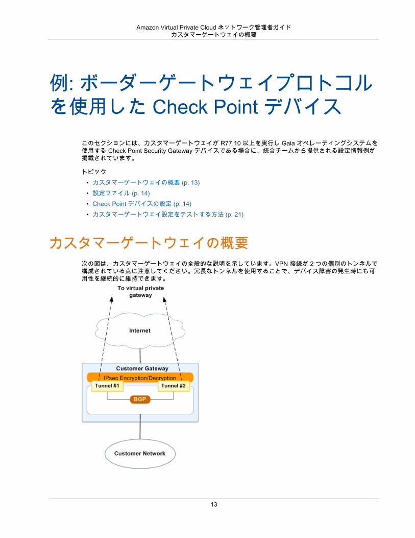
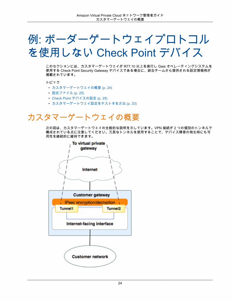
カスタマーゲートウェイの概要次の図は、カスタマーゲートウェイの全般的な説明を示しています。VPN 接続が 2 つの個別のトンネルで構成されている点に注意してください。冗長なトンネルを使用することで、デバイス障害の発生時にも可用性を継続的に維持できます。
13
Amazon Virtual Private Cloud ネットワーク管理者ガイド設定ファイル
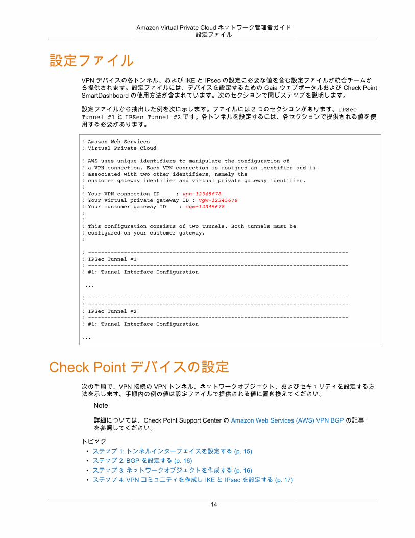
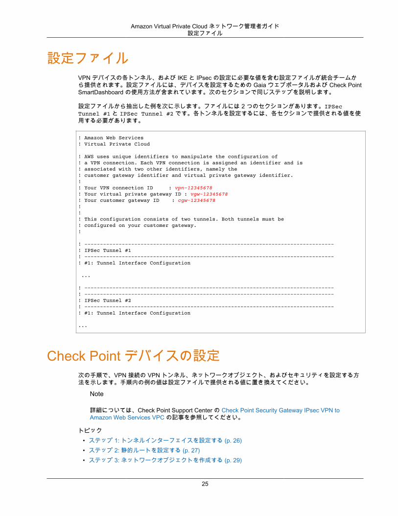
設定ファイルVPN デバイスの各トンネル、および IKE と IPsec の設定に必要な値を含む設定ファイルが統合チームから提供されます。設定ファイルには、デバイスを設定するための Gaia ウェブポータルおよび Check PointSmartDashboard の使用方法が含まれています。次のセクションで同じステップを説明します。
設定ファイルから抽出した例を次に示します。ファイルには 2 つのセクションがあります。IPSecTunnel #1 と IPSec Tunnel #2 です。各トンネルを設定するには、各セクションで提供される値を使用する必要があります。
! Amazon Web Services! Virtual Private Cloud
! AWS uses unique identifiers to manipulate the configuration of ! a VPN connection. Each VPN connection is assigned an identifier and is ! associated with two other identifiers, namely the ! customer gateway identifier and virtual private gateway identifier.!! Your VPN connection ID : vpn-12345678! Your virtual private gateway ID : vgw-12345678! Your customer gateway ID : cgw-12345678!!! This configuration consists of two tunnels. Both tunnels must be ! configured on your customer gateway.!
! --------------------------------------------------------------------------------! IPSec Tunnel #1! --------------------------------------------------------------------------------! #1: Tunnel Interface Configuration
... ! --------------------------------------------------------------------------------! --------------------------------------------------------------------------------! IPSec Tunnel #2! --------------------------------------------------------------------------------! #1: Tunnel Interface Configuration
...
Check Point デバイスの設定次の手順で、VPN 接続の VPN トンネル、ネットワークオブジェクト、およびセキュリティを設定する方法を示します。手順内の例の値は設定ファイルで提供される値に置き換えてください。
Note
詳細については、Check Point Support Center の Amazon Web Services (AWS) VPN BGP の記事を参照してください。
トピック• ステップ 1: トンネルインターフェイスを設定する (p. 15)• ステップ 2: BGP を設定する (p. 16)• ステップ 3: ネットワークオブジェクトを作成する (p. 16)• ステップ 4: VPN コミュニティを作成し IKE と IPsec を設定する (p. 17)
14
Amazon Virtual Private Cloud ネットワーク管理者ガイドステップ 1: トンネルインターフェイスを設定する
• ステップ 5: ファイアウォールを設定する (p. 19)• ステップ 6: Dead Peer Detection および TCP MSS クランプを有効にする (p. 20)
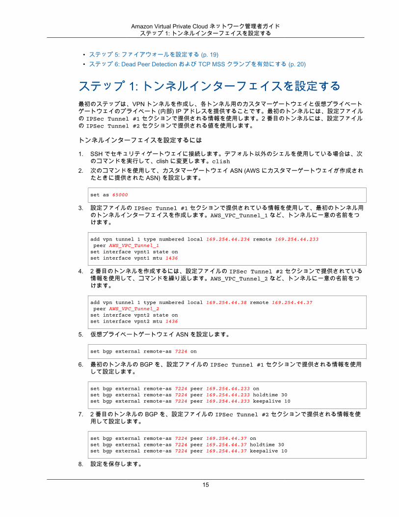
ステップ 1: トンネルインターフェイスを設定する最初のステップは、VPN トンネルを作成し、各トンネル用のカスタマーゲートウェイと仮想プライベートゲートウェイのプライベート (内部) IP アドレスを提供することです。最初のトンネルには、設定ファイルの IPSec Tunnel #1 セクションで提供される情報を使用します。2 番目のトンネルには、設定ファイルの IPSec Tunnel #2 セクションで提供される値を使用します。
トンネルインターフェイスを設定するには
1. SSH でセキュリティゲートウェイに接続します。デフォルト以外のシェルを使用している場合は、次のコマンドを実行して、clish に変更します。clish
2. 次のコマンドを使用して、カスタマーゲートウェイ ASN (AWS にカスタマーゲートウェイが作成されたときに提供された ASN) を設定します。
set as 65000
3. 設定ファイルの IPSec Tunnel #1 セクションで提供されている情報を使用して、最初のトンネル用のトンネルインターフェイスを作成します。AWS_VPC_Tunnel_1 など、トンネルに一意の名前をつけます。
add vpn tunnel 1 type numbered local 169.254.44.234 remote 169.254.44.233 peer AWS_VPC_Tunnel_1 set interface vpnt1 state on set interface vpnt1 mtu 1436
4. 2 番目のトンネルを作成するには、設定ファイルの IPSec Tunnel #2 セクションで提供されている情報を使用して、コマンドを繰り返します。AWS_VPC_Tunnel_2 など、トンネルに一意の名前をつけます。
add vpn tunnel 1 type numbered local 169.254.44.38 remote 169.254.44.37 peer AWS_VPC_Tunnel_2 set interface vpnt2 state on set interface vpnt2 mtu 1436
5. 仮想プライベートゲートウェイ ASN を設定します。
set bgp external remote-as 7224 on
6. 最初のトンネルの BGP を、設定ファイルの IPSec Tunnel #1 セクションで提供される情報を使用して設定します。
set bgp external remote-as 7224 peer 169.254.44.233 on set bgp external remote-as 7224 peer 169.254.44.233 holdtime 30set bgp external remote-as 7224 peer 169.254.44.233 keepalive 10
7. 2 番目のトンネルの BGP を、設定ファイルの IPSec Tunnel #2 セクションで提供される情報を使用して設定します。
set bgp external remote-as 7224 peer 169.254.44.37 on set bgp external remote-as 7224 peer 169.254.44.37 holdtime 30set bgp external remote-as 7224 peer 169.254.44.37 keepalive 10
8. 設定を保存します。
15
Amazon Virtual Private Cloud ネットワーク管理者ガイドステップ 2: BGP を設定する
save config
ステップ 2: BGP を設定するこのステップでは、AWS によってアドバタイズされているルートのインポートを許可する BGP ポリシーを作成し、その後カスタマーゲートウェイを設定してローカルルートを AWS にアドバタイズします。
BGP ポリシーを作成するには
1. Gaia WebUI で、[Advanced Routing]、[Inbound Route Filters] を選択します。[Add] を選択し、[AddBGP Policy (Based on AS)] を選択します。
2. [Add BGP Policy] の最初のフィールドで 512 から 1024 までの範囲の値を選択し、2 番目のフィールドに仮想プライベートゲートウェイ ASN (例: 7224) を入力します。
3. [Save] を選択します。
次のステップは、ローカルインターフェイスルートを分散するためのものです。また、静的ルーティングや、動的ルーティングプロトコルによって得られたルーティングなど、さまざまなソースからのルートを再分散できます。詳細については、「Gaia Advanced Routing R77 Versions Administration Guide」を参照してください。
ローカルルートをアドバタイズするには
1. Gaia WebUI で、[Advanced Routing]、[Routing Redistribution] の順に選択します。[Add RedistributionFrom]、[Interface] の順に選択します。
2. [To Protocol] で、仮想プライベートゲートウェイ ASN; (例: 7224) を選択します。3. [Interface] では内部インターフェイスを選択します。[Save] を選択します。
ステップ 3: ネットワークオブジェクトを作成するこのステップでは、仮想プライベートゲートウェイのパブリック (外部) IP アドレスを指定することで各VPN トンネル用のネットワークオブジェクトを作成します。後で、VPN コミュニティのサテライトゲートウェイとしてこれらのオブジェクトを追加します。また、VPN ドメインのプレースホルダーとして機能する空グループを作成する必要があります。
新しいネットワークオブジェクトを定義するには
1. Check Point SmartDashboard を開きます。2. [Groups] では、コンテキストメニューを開き、[Groups]、[Simple Group] の順に選択します。各ネッ
トワークオブジェクトに対して同じグループを使用できます。3. [Network Objects] では、コンテキストメニュー (右クリック) を開き、[New]、[Interoperable Device]
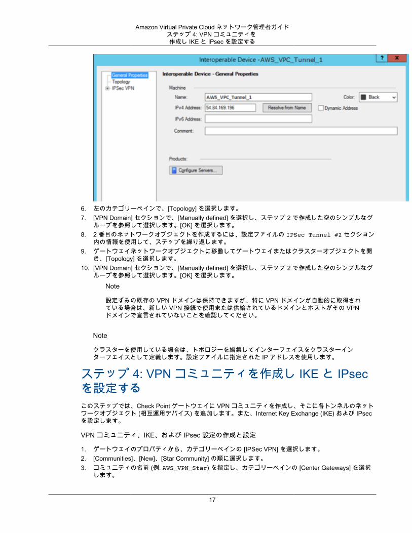
の順に選択します。4. [Name] には、ステップ 1 でトンネル用に指定した名前 (例: AWS_VPC_Tunnel_1 または
AWS_VPC_Tunnel_2) を入力します。5. [IPv4 Address] には、設定ファイルで提供される仮想プライベートゲートウェイの外部 IP アドレス
(例: 54.84.169.196) を入力します。設定を保存して、このダイアログボックスを閉じます。
16
Amazon Virtual Private Cloud ネットワーク管理者ガイドステップ 4: VPN コミュニティを作成し IKE と IPsec を設定する
6. 左のカテゴリーペインで、[Topology] を選択します。7. [VPN Domain] セクションで、[Manually defined] を選択し、ステップ 2 で作成した空のシンプルなグ
ループを参照して選択します。[OK] を選択します。8. 2 番目のネットワークオブジェクトを作成するには、設定ファイルの IPSec Tunnel #2 セクション
内の情報を使用して、ステップを繰り返します。9. ゲートウェイネットワークオブジェクトに移動してゲートウェイまたはクラスターオブジェクトを開
き、[Topology] を選択します。10. [VPN Domain] セクションで、[Manually defined] を選択し、ステップ 2 で作成した空のシンプルなグ
ループを参照して選択します。[OK] を選択します。Note
設定ずみの既存の VPN ドメインは保持できますが、特に VPN ドメインが自動的に取得されている場合は、新しい VPN 接続で使用または供給されているドメインとホストがその VPNドメインで宣言されていないことを確認してください。
Note
クラスターを使用している場合は、トポロジーを編集してインターフェイスをクラスターインターフェイスとして定義します。設定ファイルに指定された IP アドレスを使用します。
ステップ 4: VPN コミュニティを作成し IKE と IPsecを設定するこのステップでは、Check Point ゲートウェイに VPN コミュニティを作成し、そこに各トンネルのネットワークオブジェクト (相互運用デバイス) を追加します。また、Internet Key Exchange (IKE) および IPsecを設定します。
VPN コミュニティ、IKE、および IPsec 設定の作成と設定
1. ゲートウェイのプロパティから、カテゴリーペインの [IPSec VPN] を選択します。2. [Communities]、[New]、[Star Community] の順に選択します。3. コミュニティの名前 (例: AWS_VPN_Star) を指定し、カテゴリーペインの [Center Gateways] を選択
します。
17
Amazon Virtual Private Cloud ネットワーク管理者ガイドステップ 4: VPN コミュニティを作成し IKE と IPsec を設定する
4. [Add] を選択して、ゲートウェイまたはクラスターを参加ゲートウェイのリストに追加します。5. カテゴリーペインで、[Satellite Gateways]、[Add] の順に選択し、先に作成した相互運用デバイス
(AWS_VPC_Tunnel_1 および AWS_VPC_Tunnel_2) を参加ゲートウェイのリストに追加します。6. カテゴリーペインで、[Encryption] を選択します。[Encryption Method] セクションで、[IKEv1 for IPv4
and IKEv2 for IPv6] を選択します。[Encryption Suite] セクションで、[Custom]、[Custom Encryption]の順に選択します。
Note
IKEv1 機能の [IKEv1 for IPv4 and IKEv2 for IPv6] オプションを選択します。ただし、IKEv2と IPv6 は現在サポートされていません。
7. ダイアログボックスで次のように暗号化プロパティを設定し、完了したら [OK] を選択します。
• IKE Security Association (フェーズ 1) のプロパティ• Perform key exchange encryption with: AES-128• Perform data integrity with: SHA1
• IPsec Security Association (フェーズ 2) のプロパティ• Perform IPsec data encryption with: AES-128• Perform data integrity with: SHA-1
8. カテゴリーペインで [Tunnel Management] を選択します。[Set Permanent Tunnels]、[On all tunnelsin the community] の順に選択します。[VPN Tunnel Sharing] セクションで、[One VPN tunnel perGateway pair] を選択します。
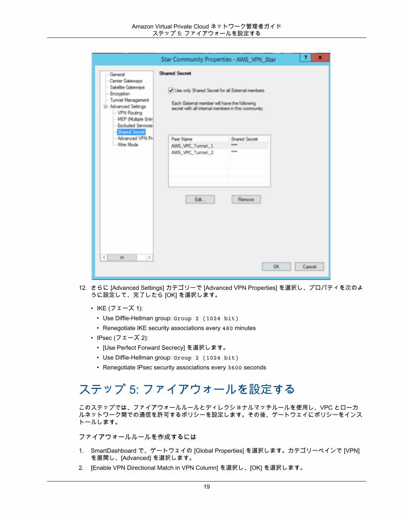
9. カテゴリーペインで [Advanced Settings] を展開し、[Shared Secret] を選択します。10. 最初のトンネルのピア名を選択し、[Edit] を選択して、設定ファイルの IPSec Tunnel #1 セクショ
ンで指定されている事前共有キーを入力します。11. 2 番目のトンネルのピア名を選択し、[Edit] を選択して、設定ファイルの IPSec Tunnel #2 セク
ションで指定されている事前共有キーを入力します。
18
Amazon Virtual Private Cloud ネットワーク管理者ガイドステップ 5: ファイアウォールを設定する
12. さらに [Advanced Settings] カテゴリーで [Advanced VPN Properties] を選択し、プロパティを次のように設定して、完了したら [OK] を選択します。
• IKE (フェーズ 1):• Use Diffie-Hellman group: Group 2 (1024 bit)• Renegotiate IKE security associations every 480 minutes
• IPsec (フェーズ 2):• [Use Perfect Forward Secrecy] を選択します。• Use Diffie-Hellman group: Group 2 (1024 bit)• Renegotiate IPsec security associations every 3600 seconds
ステップ 5: ファイアウォールを設定するこのステップでは、ファイアウォールルールとディレクショナルマッチルールを使用し、VPC とローカルネットワーク間での通信を許可するポリシーを設定します。その後、ゲートウェイにポリシーをインストールします。
ファイアウォールルールを作成するには
1. SmartDashboard で、ゲートウェイの [Global Properties] を選択します。カテゴリーペインで [VPN]を展開し、[Advanced] を選択します。
2. [Enable VPN Directional Match in VPN Column] を選択し、[OK] を選択します。
19
Amazon Virtual Private Cloud ネットワーク管理者ガイドステップ 6: Dead Peer Detection お
よび TCP MSS クランプを有効にする
3. SmartDashboard で [Firewall] を選択し、次のルールでポリシーを作成します。
• VPC サブネットに対して必須プロトコル経由でのローカルネットワークとの通信を許可する。• ローカルネットワークに対して必須プロトコル経由での VPC サブネットとの通信を許可する。
4. VPN 列のセルのコンテキストメニューを開いて、[Edit Cell] を選択します。5. [VPN Match Conditions] ダイアログボックスで、[Match traffic in this direction only] を選択します。そ
れぞれで [Add] を選択してディレクショナルマッチルールを作成し、完了したら [OK] を選択します。
• internal_clear > VPN コミュニティ (先に作成した VPN スターコミュニティ。例:AWS_VPN_Star)
• VPN コミュニティ > VPN コミュニティ• VPN コミュニティ > internal_clear
6. SmartDashboard で、[Policy]、[Install] の順に選択します。7. ダイアログボックスでゲートウェイを選択し、[OK] を選択してポリシーをインストールします。
ステップ 6: Dead Peer Detection および TCP MSS クランプを有効にするCheck Point ゲートウェイでは、IKE の関連付けが停止したときに Dead Peer Detection (DPD) を使用して識別できます。
永続トンネルに対して DPD を設定するには、永続トンネルが AWS VPN コミュニティで設定されている必要があります (「ステップ 4: VPN コミュニティを作成し IKE と IPsec を設定する (p. 17)」のステップ 8 を参照)。
デフォルトでは、VPN ゲートウェイの tunnel_keepalive_method プロパティは tunnel_testに設定されます。この値を dpd に変更する必要があります。DPD のモニタリングを必要とする VPN コミュニティの各 VPN ゲートウェイは、サードパーティの VPN ゲートウェイを含めて、tunnel_keepalive_method プロパティで設定する必要があります (同じゲートウェイに対して異なるモニタリングメカニズムを設定することはできません)。
GuiDBedit ツールを使用して tunnel_keepalive_method プロパティを更新できます。
tunnel_keepalive_method プロパティを変更するには
1. Check Point SmartDashboard を開き、[Security Management Server]、[Domain Management Server]の順に選択します。
2. [File]、[Database Revision Control...] の順に選択し、リビジョンのスナップショットを作成します。3. SmartDashboard、SmartView Tracker、SmartView Monitor など、すべての SmartConsole ウィンド
ウを閉じます。4. GuiBDedit ツールを起動します。詳細については、Check Point サポートセンターの「Check Point
Database Tool」という記事を参照してください。5. [Security Management Server]、[Domain Management Server] の順に選択します。6. 左上のペインで、[Table]、[Network Objects]、[network_objects] の順に選択します。7. 右上のペインで、関連する [Security Gateway]、[Cluster] オブジェクトを選択します。8. Ctrl+F キーを押すか、[Search] メニューを使用して以下を検索しま
す。tunnel_keepalive_method
9. 下のペインで、[tunnel_keepalive_method] のコンテキストメニューを開き、[Edit...] を選択します。[dpd] を選択し、[OK] を選択します。
10. AWS VPN コミュニティの一部である各ゲートウェイに対して、ステップ 7~9 を繰り返します。11. [File]、[Save All] の順に選択します。
20
Amazon Virtual Private Cloud ネットワーク管理者ガイドカスタマーゲートウェイ設定をテストする方法
12. GuiDBedit ツールを閉じます。13. Check Point SmartDashboard を開き、[Security Management Server]、[Domain Management Server]
の順に選択します。14. 関連する [Security Gateway]、[Cluster] オブジェクトにポリシーをインストールします。
詳細については、Check Point Support Center の「New VPN features in R77.10」という記事を参照してください。
TCP MSS クランプは TCP パケットの最大セグメントサイズを小さくしてパケット断片化を防ぎます。
TCP MSS クランプを有効にするには
1. 次のディレクトリに移動します。C:\Program Files (x86)\CheckPoint\SmartConsole\R77.10\PROGRAM\
2. GuiDBEdit.exe ファイルを実行して Check Point Database Tool を開きます。3. [Table]、[Global Properties]、[properties] の順に選択します。4. fw_clamp_tcp_mss で、[Edit] を選択します。値を true に変更し、[OK] を選択します。
カスタマーゲートウェイ設定をテストする方法各トンネルに対して、ゲートウェイ設定をテストすることができます。
各トンネルのカスタマーゲートウェイ設定をテストするには
1. カスタマーゲートウェイで、BGP ステータスが Active であるかどうかを確認します。
BGP ピアがアクティブになるまでに約 30 秒かかります。2. カスタマーゲートウェイが仮想プライベートゲートウェイへのルートをアドバタイズしていることを
確認します。このルートは、デフォルトルート (0.0.0.0/0) の場合と、任意で特定したルートの場合があります。
正しく設定されている場合、BGP ピアは、VPC 統合チームが VPC 用に指定したプレフィックス (たとえば、10.0.0.0/24) に対応する仮想プライベートゲートウェイから 1 つのルートを受け取ります。BGPピアが確立された場合は、プレフィックスを受け取り、プレフィックスをアドバタイズして、トンネルが正しく設定されます。両方のトンネルがこの状態であることを確認します。
次に、VPC でインスタンスを起動し、ホームネットワークからインスタンスへの ping を実行して、各トンネルの接続をテストする必要があります。開始する前に、以下を確認してください。
• ping リクエストに応答する AMI を使用します。Amazon Linux AMI のいずれかを使用することをお勧めします。
• インスタンスのセキュリティグループとネットワーク ACL を設定し、インバウンド ICMP トラフィックを有効にします。
• VPN 接続用のルーティングを設定していることを確認します。サブネットのルートテーブルに仮想プライベートゲートウェイへのルートが含まれている必要があります。詳細については、Amazon VPC ユーザーガイド の「ルートテーブルでルート伝達を有効にする」を参照してください。
各トンネルのエンドツーエンド接続をテストするには
1. VPC で Amazon Linux AMI の 1 つのインスタンスを起動します。Amazon EC2 コンソールからインスタンスを起動すると、起動ウィザードのリストに Amazon Linux AMI が表示されます。詳細については、「Amazon VPC 入門ガイド」を参照してください。
21
Amazon Virtual Private Cloud ネットワーク管理者ガイドカスタマーゲートウェイ設定をテストする方法
2. インスタンスが実行中になった後、そのプライベート IP アドレス (例えば 10.0.0.4) を取得します。 コンソールにインスタンスの詳細の一部としてアドレスが表示されます。
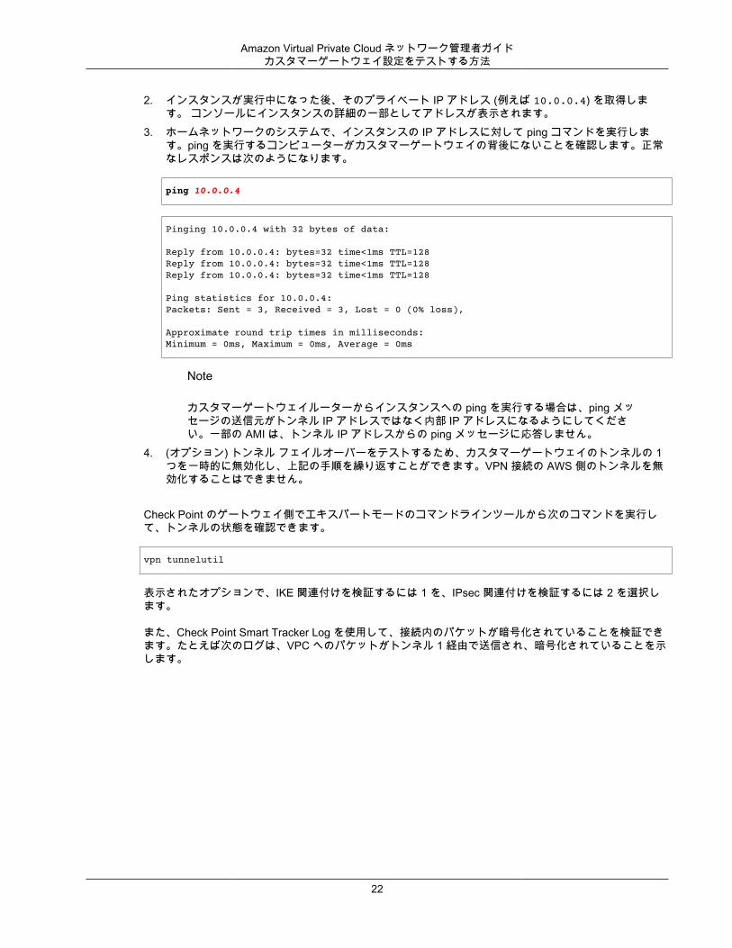
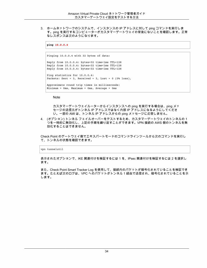
3. ホームネットワークのシステムで、インスタンスの IP アドレスに対して ping コマンドを実行します。ping を実行するコンピューターがカスタマーゲートウェイの背後にないことを確認します。正常なレスポンスは次のようになります。
ping 10.0.0.4
Pinging 10.0.0.4 with 32 bytes of data:
Reply from 10.0.0.4: bytes=32 time<1ms TTL=128Reply from 10.0.0.4: bytes=32 time<1ms TTL=128Reply from 10.0.0.4: bytes=32 time<1ms TTL=128
Ping statistics for 10.0.0.4:Packets: Sent = 3, Received = 3, Lost = 0 (0% loss),
Approximate round trip times in milliseconds:Minimum = 0ms, Maximum = 0ms, Average = 0ms
Note
カスタマーゲートウェイルーターからインスタンスへの ping を実行する場合は、ping メッセージの送信元がトンネル IP アドレスではなく内部 IP アドレスになるようにしてください。一部の AMI は、トンネル IP アドレスからの ping メッセージに応答しません。
4. (オプション) トンネル フェイルオーバーをテストするため、カスタマーゲートウェイのトンネルの 1つを一時的に無効化し、上記の手順を繰り返すことができます。VPN 接続の AWS 側のトンネルを無効化することはできません。
Check Point のゲートウェイ側でエキスパートモードのコマンドラインツールから次のコマンドを実行して、トンネルの状態を確認できます。
vpn tunnelutil
表示されたオプションで、IKE 関連付けを検証するには 1 を、IPsec 関連付けを検証するには 2 を選択します。
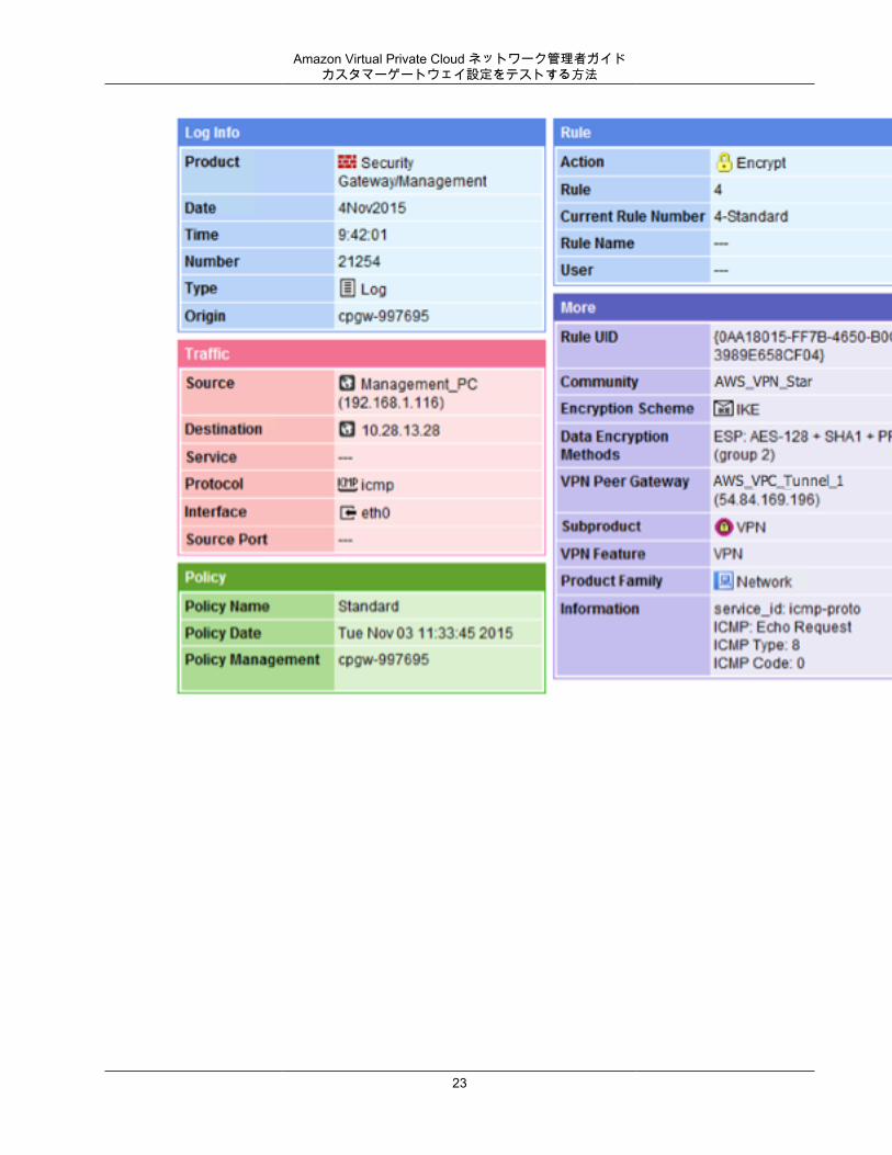
また、Check Point Smart Tracker Log を使用して、接続内のパケットが暗号化されていることを検証できます。たとえば次のログは、VPC へのパケットがトンネル 1 経由で送信され、暗号化されていることを示します。
22
Amazon Virtual Private Cloud ネットワーク管理者ガイドカスタマーゲートウェイ設定をテストする方法
23
Amazon Virtual Private Cloud ネットワーク管理者ガイドカスタマーゲートウェイの概要
例: ボーダーゲートウェイプロトコルを使用しない Check Point デバイス
このセクションには、カスタマーゲートウェイが R77.10 以上を実行し Gaia オペレーティングシステムを使用する Check Point Security Gateway デバイスである場合に、統合チームから提供される設定情報例が掲載されています。
トピック• カスタマーゲートウェイの概要 (p. 24)• 設定ファイル (p. 25)• Check Point デバイスの設定 (p. 25)• カスタマーゲートウェイ設定をテストする方法 (p. 33)
カスタマーゲートウェイの概要次の図は、カスタマーゲートウェイの全般的な説明を示しています。VPN 接続が 2 つの個別のトンネルで構成されている点に注意してください。冗長なトンネルを使用することで、デバイス障害の発生時にも可用性を継続的に維持できます。
24
Amazon Virtual Private Cloud ネットワーク管理者ガイド設定ファイル
設定ファイルVPN デバイスの各トンネル、および IKE と IPsec の設定に必要な値を含む設定ファイルが統合チームから提供されます。設定ファイルには、デバイスを設定するための Gaia ウェブポータルおよび Check PointSmartDashboard の使用方法が含まれています。次のセクションで同じステップを説明します。
設定ファイルから抽出した例を次に示します。ファイルには 2 つのセクションがあります。IPSecTunnel #1 と IPSec Tunnel #2 です。各トンネルを設定するには、各セクションで提供される値を使用する必要があります。
! Amazon Web Services! Virtual Private Cloud
! AWS uses unique identifiers to manipulate the configuration of ! a VPN connection. Each VPN connection is assigned an identifier and is ! associated with two other identifiers, namely the ! customer gateway identifier and virtual private gateway identifier.!! Your VPN connection ID : vpn-12345678! Your virtual private gateway ID : vgw-12345678! Your customer gateway ID : cgw-12345678!!! This configuration consists of two tunnels. Both tunnels must be ! configured on your customer gateway.!
! --------------------------------------------------------------------------------! IPSec Tunnel #1! --------------------------------------------------------------------------------! #1: Tunnel Interface Configuration
... ! --------------------------------------------------------------------------------! --------------------------------------------------------------------------------! IPSec Tunnel #2! --------------------------------------------------------------------------------! #1: Tunnel Interface Configuration
...
Check Point デバイスの設定次の手順で、VPN 接続の VPN トンネル、ネットワークオブジェクト、およびセキュリティを設定する方法を示します。手順内の例の値は設定ファイルで提供される値に置き換えてください。
Note
詳細については、Check Point Support Center の Check Point Security Gateway IPsec VPN toAmazon Web Services VPC の記事を参照してください。
トピック• ステップ 1: トンネルインターフェイスを設定する (p. 26)• ステップ 2: 静的ルートを設定する (p. 27)• ステップ 3: ネットワークオブジェクトを作成する (p. 29)
25
Amazon Virtual Private Cloud ネットワーク管理者ガイドステップ 1: トンネルインターフェイスを設定する
• ステップ 4: VPN コミュニティを作成し IKE と IPsec を設定する (p. 30)• ステップ 5: ファイアウォールを設定する (p. 31)• ステップ 6: Dead Peer Detection および TCP MSS クランプを有効にする (p. 32)
ステップ 1: トンネルインターフェイスを設定する最初のステップは、VPN トンネルを作成し、各トンネル用のカスタマーゲートウェイと仮想プライベートゲートウェイのプライベート (内部) IP アドレスを提供することです。最初のトンネルを作成するには、設定ファイルの IPSec Tunnel #1 セクションで提供される情報を使用します。2 番目のトンネルを作成するには、設定ファイルの IPSec Tunnel #2 セクションで提供される値を使用します。
トンネルインターフェイスを設定するには
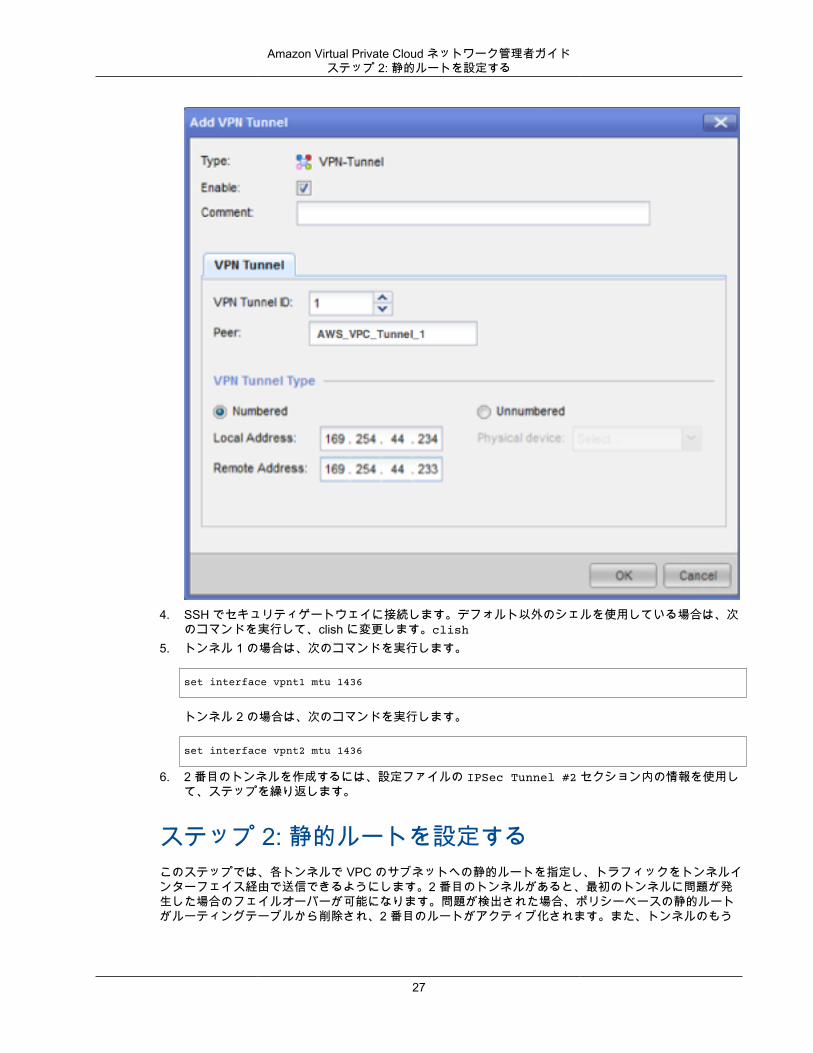
1. Check Point Security Gateway デバイスの Gaia ポータルを開きます。2. [Network Interfaces]、[Add]、[VPN tunnel] の順に選択します。3. ダイアログボックスで次のように設定し、完了したら [OK] を選択します。
• [VPN Tunnel ID] には、1 など一意の値を入力します。• [Peer] には、AWS_VPC_Tunnel_1 または AWS_VPC_Tunnel_2 など、トンネル用の一意の名前を
入力します。• [Numbered] が選択されていることを確認して、[Local Address] に設定ファイルの CGW TunnelIP で指定されている IP アドレス (例: 169.254.44.234) を入力します。
• [Remote Address] には、設定ファイルの VGW Tunnel IP に指定された IP アドレス (例:169.254.44.233) を入力します。
26
Amazon Virtual Private Cloud ネットワーク管理者ガイドステップ 2: 静的ルートを設定する
4. SSH でセキュリティゲートウェイに接続します。デフォルト以外のシェルを使用している場合は、次のコマンドを実行して、clish に変更します。clish
5. トンネル 1 の場合は、次のコマンドを実行します。
set interface vpnt1 mtu 1436
トンネル 2 の場合は、次のコマンドを実行します。
set interface vpnt2 mtu 1436
6. 2 番目のトンネルを作成するには、設定ファイルの IPSec Tunnel #2 セクション内の情報を使用して、ステップを繰り返します。
ステップ 2: 静的ルートを設定するこのステップでは、各トンネルで VPC のサブネットへの静的ルートを指定し、トラフィックをトンネルインターフェイス経由で送信できるようにします。2 番目のトンネルがあると、最初のトンネルに問題が発生した場合のフェイルオーバーが可能になります。問題が検出された場合、ポリシーベースの静的ルートがルーティングテーブルから削除され、2 番目のルートがアクティブ化されます。また、トンネルのもう
27
Amazon Virtual Private Cloud ネットワーク管理者ガイドステップ 2: 静的ルートを設定する
一方の端に ping を打ち、トンネルが稼働しているかどうかを確認するために、Check Point ゲートウェイを有効にする必要があります。
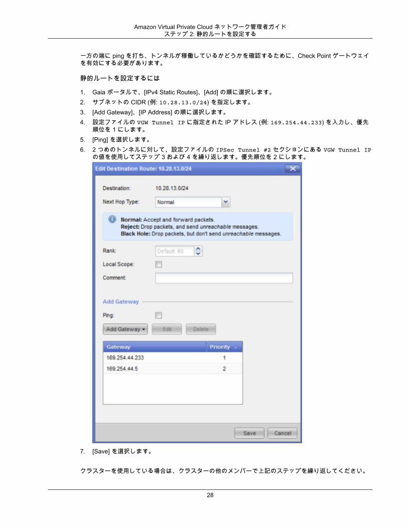
静的ルートを設定するには
1. Gaia ポータルで、[IPv4 Static Routes]、[Add] の順に選択します。2. サブネットの CIDR (例: 10.28.13.0/24) を指定します。3. [Add Gateway]、[IP Address] の順に選択します。4. 設定ファイルの VGW Tunnel IP に指定された IP アドレス (例: 169.254.44.233) を入力し、優先
順位を 1 にします。5. [Ping] を選択します。6. 2 つめのトンネルに対して、設定ファイルの IPSec Tunnel #2 セクションにある VGW Tunnel IP
の値を使用してステップ 3 および 4 を繰り返します。優先順位を 2 にします。
7. [Save] を選択します。
クラスターを使用している場合は、クラスターの他のメンバーで上記のステップを繰り返してください。
28
Amazon Virtual Private Cloud ネットワーク管理者ガイドステップ 3: ネットワークオブジェクトを作成する
ステップ 3: ネットワークオブジェクトを作成するこのステップでは、仮想プライベートゲートウェイのパブリック (外部) IP アドレスを指定することで各VPN トンネル用のネットワークオブジェクトを作成します。後で、VPN コミュニティのサテライトゲートウェイとしてこれらのオブジェクトを追加します。また、VPN ドメインのプレースホルダーとして機能する空グループを作成する必要があります。
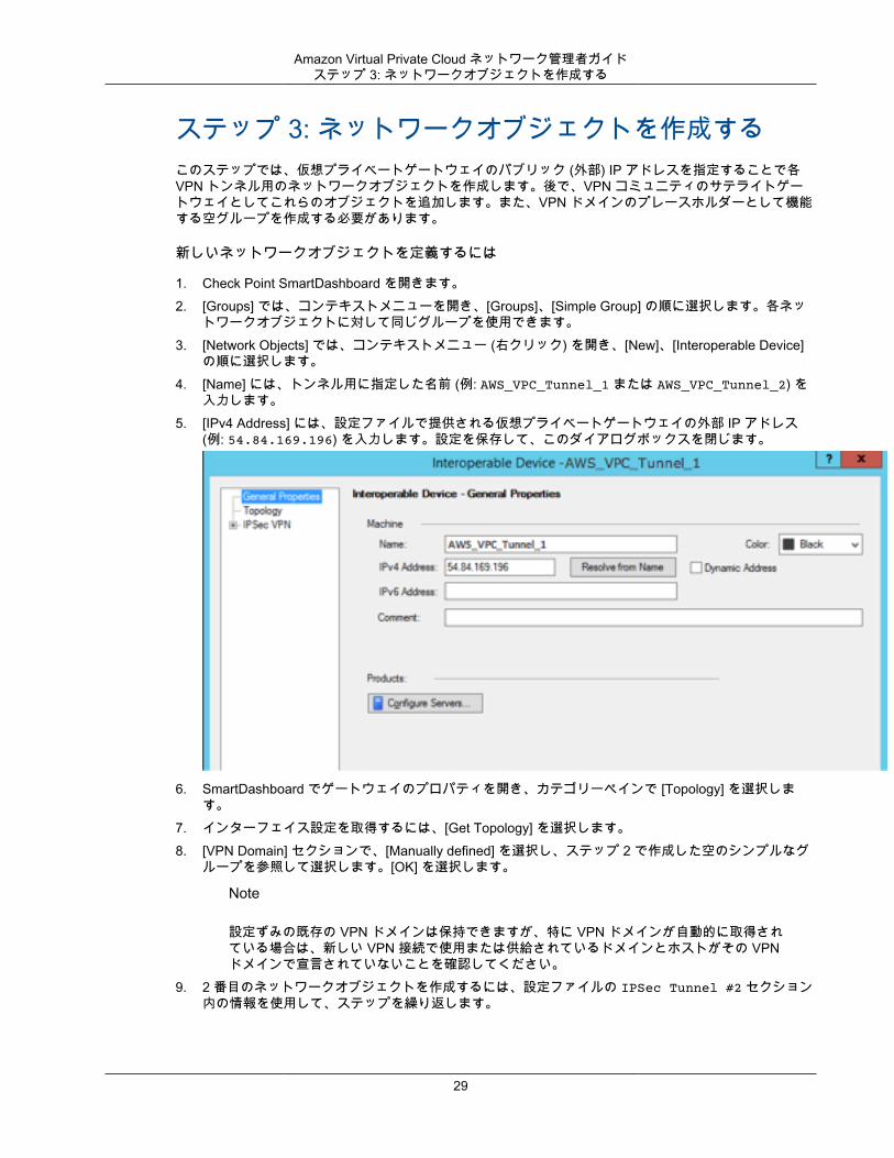
新しいネットワークオブジェクトを定義するには
1. Check Point SmartDashboard を開きます。2. [Groups] では、コンテキストメニューを開き、[Groups]、[Simple Group] の順に選択します。各ネッ
トワークオブジェクトに対して同じグループを使用できます。3. [Network Objects] では、コンテキストメニュー (右クリック) を開き、[New]、[Interoperable Device]
の順に選択します。4. [Name] には、トンネル用に指定した名前 (例: AWS_VPC_Tunnel_1 または AWS_VPC_Tunnel_2) を
入力します。5. [IPv4 Address] には、設定ファイルで提供される仮想プライベートゲートウェイの外部 IP アドレス
(例: 54.84.169.196) を入力します。設定を保存して、このダイアログボックスを閉じます。
6. SmartDashboard でゲートウェイのプロパティを開き、カテゴリーペインで [Topology] を選択します。
7. インターフェイス設定を取得するには、[Get Topology] を選択します。8. [VPN Domain] セクションで、[Manually defined] を選択し、ステップ 2 で作成した空のシンプルなグ
ループを参照して選択します。[OK] を選択します。
Note
設定ずみの既存の VPN ドメインは保持できますが、特に VPN ドメインが自動的に取得されている場合は、新しい VPN 接続で使用または供給されているドメインとホストがその VPNドメインで宣言されていないことを確認してください。
9. 2 番目のネットワークオブジェクトを作成するには、設定ファイルの IPSec Tunnel #2 セクション内の情報を使用して、ステップを繰り返します。
29
Amazon Virtual Private Cloud ネットワーク管理者ガイドステップ 4: VPN コミュニティを作成し IKE と IPsec を設定する
Note
クラスターを使用している場合は、トポロジーを編集してインターフェイスをクラスターインターフェイスとして定義します。設定ファイルに指定された IP アドレスを使用します。
ステップ 4: VPN コミュニティを作成し IKE と IPsecを設定するこのステップでは、Check Point ゲートウェイに VPN コミュニティを作成し、そこに各トンネルのネットワークオブジェクト (相互運用デバイス) を追加します。また、Internet Key Exchange (IKE) および IPsecを設定します。
VPN コミュニティ、IKE、および IPsec 設定の作成と設定
1. ゲートウェイのプロパティから、カテゴリーペインの [IPSec VPN] を選択します。2. [Communities]、[New]、[Star Community] の順に選択します。3. コミュニティの名前 (例: AWS_VPN_Star) を指定し、カテゴリーペインの [Center Gateways] を選択
します。4. [Add] を選択して、ゲートウェイまたはクラスターを参加ゲートウェイのリストに追加します。5. カテゴリーペインで、[Satellite Gateways]、[Add] の順に選択し、先に作成した相互運用デバイス
(AWS_VPC_Tunnel_1 および AWS_VPC_Tunnel_2) を参加ゲートウェイのリストに追加します。6. カテゴリーペインで、[Encryption] を選択します。[Encryption Method] セクションで、[IKEv1 only] を
選択します。[Encryption Suite] セクションで、[Custom]、[Custom Encryption] の順に選択します。7. ダイアログボックスで次のように暗号化プロパティを設定し、完了したら [OK] を選択します。
• IKE Security Association (フェーズ 1) のプロパティ• Perform key exchange encryption with: AES-128• Perform data integrity with: SHA1
• IPsec Security Association (フェーズ 2) のプロパティ• Perform IPsec data encryption with: AES-128• Perform data integrity with: SHA-1
8. カテゴリーペインで [Tunnel Management] を選択します。[Set Permanent Tunnels]、[On all tunnelsin the community] の順に選択します。[VPN Tunnel Sharing] セクションで、[One VPN tunnel perGateway pair] を選択します。
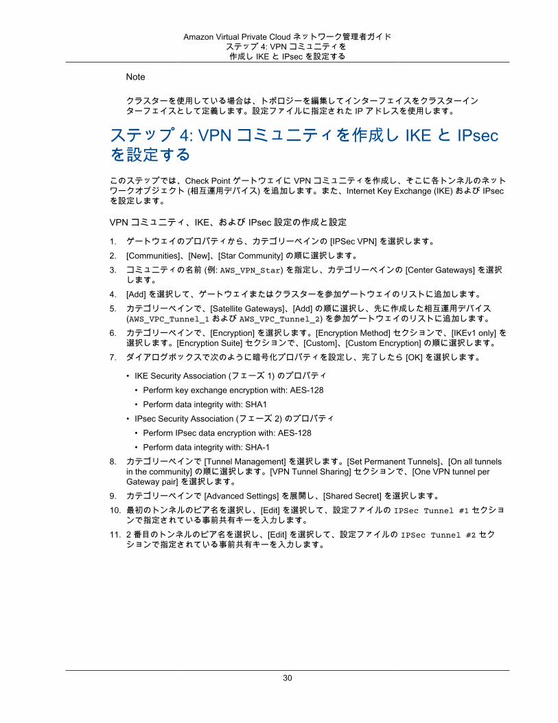
9. カテゴリーペインで [Advanced Settings] を展開し、[Shared Secret] を選択します。10. 最初のトンネルのピア名を選択し、[Edit] を選択して、設定ファイルの IPSec Tunnel #1 セクショ
ンで指定されている事前共有キーを入力します。11. 2 番目のトンネルのピア名を選択し、[Edit] を選択して、設定ファイルの IPSec Tunnel #2 セク
ションで指定されている事前共有キーを入力します。
30
Amazon Virtual Private Cloud ネットワーク管理者ガイドステップ 5: ファイアウォールを設定する
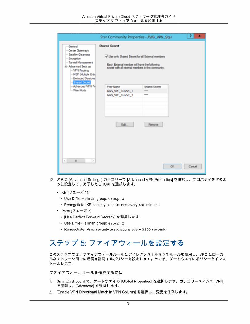
12. さらに [Advanced Settings] カテゴリーで [Advanced VPN Properties] を選択し、プロパティを次のように設定して、完了したら [OK] を選択します。
• IKE (フェーズ 1):• Use Diffie-Hellman group: Group 2• Renegotiate IKE security associations every 480 minutes
• IPsec (フェーズ 2):• [Use Perfect Forward Secrecy] を選択します。• Use Diffie-Hellman group: Group 2• Renegotiate IPsec security associations every 3600 seconds
ステップ 5: ファイアウォールを設定するこのステップでは、ファイアウォールルールとディレクショナルマッチルールを使用し、VPC とローカルネットワーク間での通信を許可するポリシーを設定します。その後、ゲートウェイにポリシーをインストールします。
ファイアウォールルールを作成するには
1. SmartDashboard で、ゲートウェイの [Global Properties] を選択します。カテゴリーペインで [VPN]を展開し、[Advanced] を選択します。
2. [Enable VPN Directional Match in VPN Column] を選択し、変更を保存します。
31
Amazon Virtual Private Cloud ネットワーク管理者ガイドステップ 6: Dead Peer Detection お
よび TCP MSS クランプを有効にする
3. SmartDashboard で [Firewall] を選択し、次のルールでポリシーを作成します。
• VPC サブネットに対して必須プロトコル経由でのローカルネットワークとの通信を許可する。• ローカルネットワークに対して必須プロトコル経由での VPC サブネットとの通信を許可する。
4. VPN 列のセルのコンテキストメニューを開いて、[Edit Cell] を選択します。5. [VPN Match Conditions] ダイアログボックスで、[Match traffic in this direction only] を選択します。そ
れぞれで [Add] を選択してディレクショナルマッチルールを作成し、完了したら [OK] を選択します。
• internal_clear > VPN コミュニティ (先に作成した VPN スターコミュニティ。例:AWS_VPN_Star)
• VPN コミュニティ > VPN コミュニティ• VPN コミュニティ > internal_clear
6. SmartDashboard で、[Policy]、[Install] の順に選択します。7. ダイアログボックスでゲートウェイを選択し、[OK] を選択してポリシーをインストールします。
ステップ 6: Dead Peer Detection および TCP MSS クランプを有効にするCheck Point ゲートウェイでは、IKE の関連付けが停止したときに Dead Peer Detection (DPD) を使用して識別できます。
永続トンネルに対して DPD を設定するには、永続トンネルが AWS VPN コミュニティで設定されている必要があります (「ステップ 4: VPN コミュニティを作成し IKE と IPsec を設定する (p. 30)」のステップ 8 を参照)。
デフォルトでは、VPN ゲートウェイの tunnel_keepalive_method プロパティは tunnel_testに設定されます。この値を dpd に変更する必要があります。DPD のモニタリングを必要とする VPN コミュニティの各 VPN ゲートウェイは、サードパーティの VPN ゲートウェイを含めて、tunnel_keepalive_method プロパティで設定する必要があります (同じゲートウェイに対して異なるモニタリングメカニズムを設定することはできません)。
GuiDBedit ツールを使用して tunnel_keepalive_method プロパティを更新できます。
tunnel_keepalive_method プロパティを変更するには
1. Check Point SmartDashboard を開き、[Security Management Server]、[Domain Management Server]の順に選択します。
2. [File]、[Database Revision Control...] の順に選択し、リビジョンのスナップショットを作成します。3. SmartDashboard、SmartView Tracker、SmartView Monitor など、すべての SmartConsole ウィンド
ウを閉じます。4. GuiBDedit ツールを起動します。詳細については、Check Point サポートセンターの「Check Point
Database Tool」という記事を参照してください。5. [Security Management Server]、[Domain Management Server] の順に選択します。6. 左上のペインで、[Table]、[Network Objects]、[network_objects] の順に選択します。7. 右上のペインで、関連する [Security Gateway]、[Cluster] オブジェクトを選択します。8. Ctrl+F キーを押すか、[Search] メニューを使用して以下を検索しま
す。tunnel_keepalive_method
9. 下のペインで、[tunnel_keepalive_method] のコンテキストメニューを開き、[Edit...] を選択します。[dpd] を選択し、[OK] を選択します。
10. AWS VPN コミュニティの一部である各ゲートウェイに対して、ステップ 7~9 を繰り返します。
32
Amazon Virtual Private Cloud ネットワーク管理者ガイドカスタマーゲートウェイ設定をテストする方法
11. [File]、[Save All] の順に選択します。12. GuiDBedit ツールを閉じます。13. Check Point SmartDashboard を開き、[Security Management Server]、[Domain Management Server]
の順に選択します。14. 関連する [Security Gateway]、[Cluster] オブジェクトにポリシーをインストールします。
詳細については、Check Point Support Center の「New VPN features in R77.10」という記事を参照してください。
TCP MSS クランプは TCP パケットの最大セグメントサイズを小さくしてパケット断片化を防ぎます。
TCP MSS クランプを有効にするには
1. 次のディレクトリに移動します。C:\Program Files (x86)\CheckPoint\SmartConsole\R77.10\PROGRAM\
2. GuiDBEdit.exe ファイルを実行して Check Point Database Tool を開きます。3. [Table]、[Global Properties]、[properties] の順に選択します。4. fw_clamp_tcp_mss で、[Edit] を選択します。値を true に変更し、[OK] を選択します。
カスタマーゲートウェイ設定をテストする方法各トンネルに対して、ゲートウェイ設定をテストすることができます。
各トンネルのカスタマーゲートウェイ設定をテストするには
1. AWS によって提供される設定テンプレートで指示されているとおり、カスタマーゲートウェイにVPC への静的ルートがあることを確認します。
2. 静的ルートが VPN 接続に追加され、トラフィックがカスタマーゲートウェイに戻るようになっていることを確認します。たとえば、ローカルサブネットのプレフィックスが 198.10.0.0/16 の場合、その CIDR 範囲の静的ルートを VPN 接続に追加する必要があります。両方のトンネルに VPC への静的ルートがあることを確認します。
次に、VPC でインスタンスを起動し、ホームネットワークからインスタンスへの ping を実行して、各トンネルの接続をテストする必要があります。開始する前に、以下を確認してください。
• ping リクエストに応答する AMI を使用します。Amazon Linux AMI のいずれかを使用することをお勧めします。
• インスタンスのセキュリティグループとネットワーク ACL を設定し、インバウンド ICMP トラフィックを有効にします。
• VPN 接続用のルーティングを設定していることを確認します。サブネットのルートテーブルに仮想プライベートゲートウェイへのルートが含まれている必要があります。詳細については、Amazon VPC ユーザーガイド の「ルートテーブルでルート伝達を有効にする」を参照してください。
各トンネルのエンドツーエンド接続をテストするには
1. VPC で Amazon Linux AMI の 1 つのインスタンスを起動します。AWS マネジメントコンソールからインスタンスを起動すると、起動ウィザードのリストに Amazon Linux AMI が表示されます。詳細については、「Amazon VPC 入門ガイド」を参照してください。
2. インスタンスが実行中になった後、そのプライベート IP アドレス (例えば 10.0.0.4) を取得します。 コンソールにインスタンスの詳細の一部としてアドレスが表示されます。
33
Amazon Virtual Private Cloud ネットワーク管理者ガイドカスタマーゲートウェイ設定をテストする方法
3. ホームネットワークのシステムで、インスタンスの IP アドレスに対して ping コマンドを実行します。ping を実行するコンピューターがカスタマーゲートウェイの背後にないことを確認します。正常なレスポンスは次のようになります。
ping 10.0.0.4
Pinging 10.0.0.4 with 32 bytes of data:
Reply from 10.0.0.4: bytes=32 time<1ms TTL=128Reply from 10.0.0.4: bytes=32 time<1ms TTL=128Reply from 10.0.0.4: bytes=32 time<1ms TTL=128
Ping statistics for 10.0.0.4:Packets: Sent = 3, Received = 3, Lost = 0 (0% loss),
Approximate round trip times in milliseconds:Minimum = 0ms, Maximum = 0ms, Average = 0ms
Note
カスタマーゲートウェイルーターからインスタンスへの ping を実行する場合は、ping メッセージの送信元がトンネル IP アドレスではなく内部 IP アドレスになるようにしてください。一部の AMI は、トンネル IP アドレスからの ping メッセージに応答しません。
4. (オプション) トンネル フェイルオーバーをテストするため、カスタマーゲートウェイのトンネルの 1つを一時的に無効化し、上記の手順を繰り返すことができます。VPN 接続の AWS 側のトンネルを無効化することはできません。
Check Point のゲートウェイ側でエキスパートモードのコマンドラインツールから次のコマンドを実行して、トンネルの状態を確認できます。
vpn tunnelutil
表示されたオプションで、IKE 関連付けを検証するには 1 を、IPsec 関連付けを検証するには 2 を選択します。
また、Check Point Smart Tracker Log を使用して、接続内のパケットが暗号化されていることを検証できます。たとえば次のログは、VPC へのパケットがトンネル 1 経由で送信され、暗号化されていることを示します。
34

Amazon Virtual Private Cloud ネットワーク管理者ガイドカスタマーゲートウェイ設定をテストする方法
35
Amazon Virtual Private Cloud ネットワーク管理者ガイドカスタマーゲートウェイの概要
例: Cisco ASA デバイストピック
• カスタマーゲートウェイの概要 (p. 36)• 設定例 (p. 37)• カスタマーゲートウェイ設定をテストする方法 (p. 41)
このセクションでは、Cisco ASA 8.2+ ソフトウェアを実行している Cisco ASA デバイスをカスタマーゲートウェイとして使用する場合に、統合チームから提供される設定情報の例について説明します。
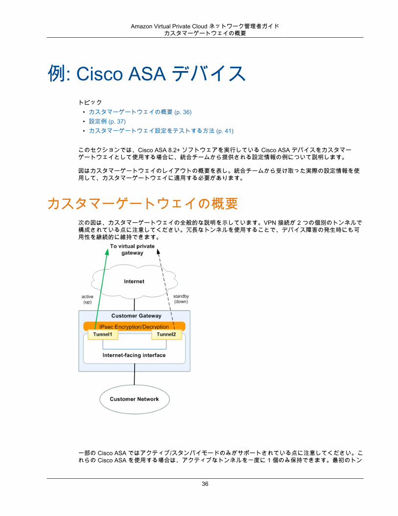
図はカスタマーゲートウェイのレイアウトの概要を表し。統合チームから受け取った実際の設定情報を使用して、カスタマーゲートウェイに適用する必要があります。
カスタマーゲートウェイの概要次の図は、カスタマーゲートウェイの全般的な説明を示しています。VPN 接続が 2 つの個別のトンネルで構成されている点に注意してください。冗長なトンネルを使用することで、デバイス障害の発生時にも可用性を継続的に維持できます。
一部の Cisco ASA ではアクティブ/スタンバイモードのみがサポートされている点に注意してください。これらの Cisco ASA を使用する場合は、アクティブなトンネルを一度に 1 個のみ保持できます。最初のトン
36
Amazon Virtual Private Cloud ネットワーク管理者ガイド設定例
ネルが利用不可になった場合は、他方のスタンバイトンネルがアクティブになります。この冗長化では、常にいずれかのトンネルを経由して VPC への接続を保持する必要があります。
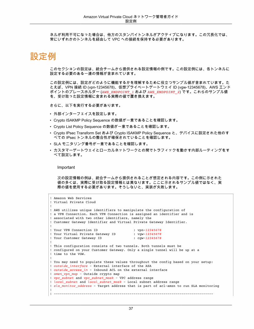
設定例このセクションの設定は、統合チームから提供される設定情報の例です。この設定例には、各トンネルに設定する必要のある一連の情報が含まれています。
この設定例には、設定がどのように機能するかを理解するために役立つサンプル値が含まれています。たとえば、VPN 接続 ID (vpn-12345678)、仮想プライベートゲートウェイ ID (vgw-12345678)、AWS エンドポイントのプレースホルダー (AWS_ENDPOINT_1 および AWS_ENDPOINT_2) です。これらのサンプル値を、受け取った設定情報に含まれる実際の値で置き換えます。
さらに、以下を実行する必要があります。
• 外部インターフェイスを設定します。• Crypto ISAKMP Policy Sequence の数値が一意であることを確認します。• Crypto List Policy Sequence の数値が一意であることを確認します。• Crypto IPsec Transform Set および Crypto ISAKMP Policy Sequence と、デバイスに設定された他のす
べての IPsec トンネルの整合性が確保されていることを確認します。• SLA モニタリング番号が一意であることを確認します。• カスタマーゲートウェイとローカルネットワークとの間でトラフィックを動かす内部ルーティングをす
べて設定します。
Important
次の設定情報の例は、統合チームから提供されることが想定される内容です。この例に示された値の多くは、実際に受け取る設定情報とは異なります。ここに示されるサンプル値ではなく、実際の値を使用する必要があります。そうしないと、実装が失敗します。
! Amazon Web Services! Virtual Private Cloud!! AWS utilizes unique identifiers to manipulate the configuration of ! a VPN Connection. Each VPN Connection is assigned an identifier and is ! associated with two other identifiers, namely the ! Customer Gateway Identifier and Virtual Private Gateway Identifier.!! Your VPN Connection ID : vpn-12345678! Your Virtual Private Gateway ID : vgw-12345678! Your Customer Gateway ID : cgw-12345678!! This configuration consists of two tunnels. Both tunnels must be ! configured on your Customer Gateway. Only a single tunnel will be up at a! time to the VGW.! ! You may need to populate these values throughout the config based on your setup:! outside_interface - External interface of the ASA! outside_access_in - Inbound ACL on the external interface! amzn_vpn_map - Outside crypto map! vpc_subnet and vpc_subnet_mask - VPC address range! local_subnet and local_subnet_mask - Local subnet address range! sla_monitor_address - Target address that is part of acl-amzn to run SLA monitoring!! --------------------------------------------------------------------------------
37
Amazon Virtual Private Cloud ネットワーク管理者ガイド設定例
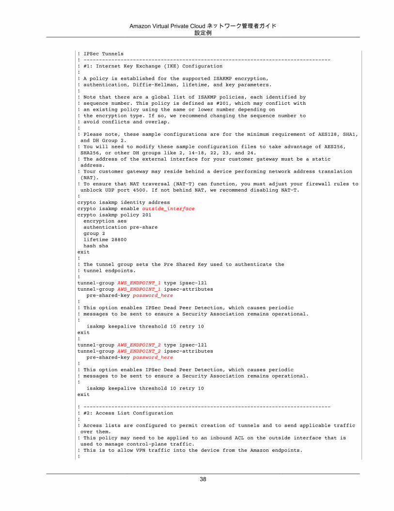
! IPSec Tunnels! --------------------------------------------------------------------------------! #1: Internet Key Exchange (IKE) Configuration!! A policy is established for the supported ISAKMP encryption, ! authentication, Diffie-Hellman, lifetime, and key parameters.!! Note that there are a global list of ISAKMP policies, each identified by ! sequence number. This policy is defined as #201, which may conflict with! an existing policy using the same or lower number depending on ! the encryption type. If so, we recommend changing the sequence number to ! avoid conflicts and overlap.!! Please note, these sample configurations are for the minimum requirement of AES128, SHA1, and DH Group 2.! You will need to modify these sample configuration files to take advantage of AES256, SHA256, or other DH groups like 2, 14-18, 22, 23, and 24.! The address of the external interface for your customer gateway must be a static address. ! Your customer gateway may reside behind a device performing network address translation (NAT).! To ensure that NAT traversal (NAT-T) can function, you must adjust your firewall rules to unblock UDP port 4500. If not behind NAT, we recommend disabling NAT-T.!crypto isakmp identity address crypto isakmp enable outside_interfacecrypto isakmp policy 201 encryption aes authentication pre-share group 2 lifetime 28800 hash shaexit!! The tunnel group sets the Pre Shared Key used to authenticate the ! tunnel endpoints.!tunnel-group AWS_ENDPOINT_1 type ipsec-l2ltunnel-group AWS_ENDPOINT_1 ipsec-attributes pre-shared-key password_here!! This option enables IPSec Dead Peer Detection, which causes periodic! messages to be sent to ensure a Security Association remains operational.! isakmp keepalive threshold 10 retry 10exit!tunnel-group AWS_ENDPOINT_2 type ipsec-l2ltunnel-group AWS_ENDPOINT_2 ipsec-attributes pre-shared-key password_here!! This option enables IPSec Dead Peer Detection, which causes periodic! messages to be sent to ensure a Security Association remains operational.! isakmp keepalive threshold 10 retry 10exit
! --------------------------------------------------------------------------------! #2: Access List Configuration!! Access lists are configured to permit creation of tunnels and to send applicable traffic over them.! This policy may need to be applied to an inbound ACL on the outside interface that is used to manage control-plane traffic. ! This is to allow VPN traffic into the device from the Amazon endpoints.!
38
Amazon Virtual Private Cloud ネットワーク管理者ガイド設定例
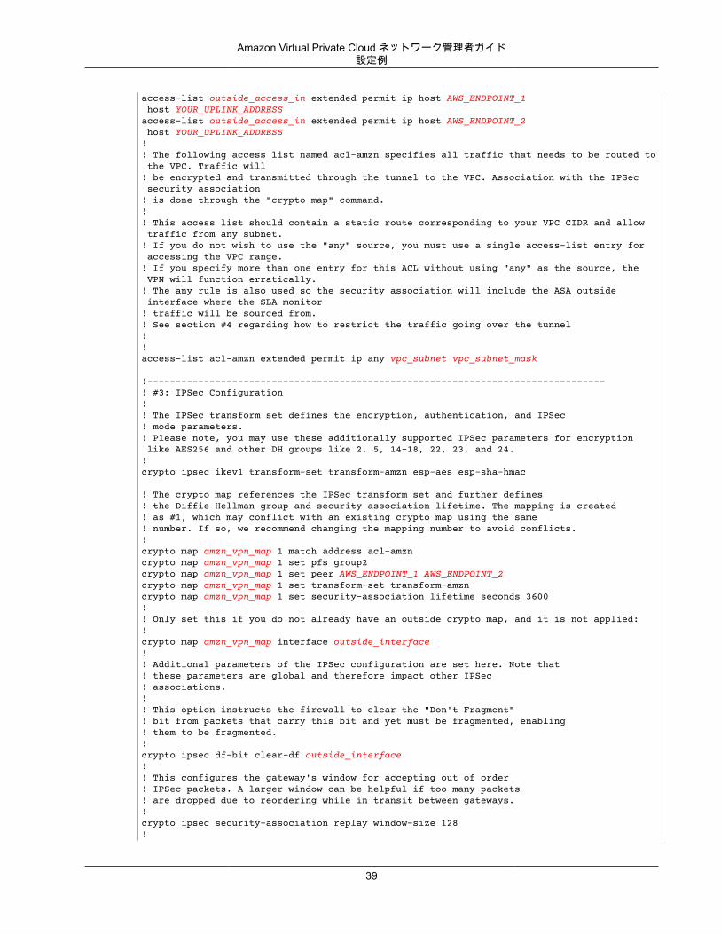
access-list outside_access_in extended permit ip host AWS_ENDPOINT_1 host YOUR_UPLINK_ADDRESSaccess-list outside_access_in extended permit ip host AWS_ENDPOINT_2 host YOUR_UPLINK_ADDRESS!! The following access list named acl-amzn specifies all traffic that needs to be routed to the VPC. Traffic will! be encrypted and transmitted through the tunnel to the VPC. Association with the IPSec security association! is done through the "crypto map" command.!! This access list should contain a static route corresponding to your VPC CIDR and allow traffic from any subnet.! If you do not wish to use the "any" source, you must use a single access-list entry for accessing the VPC range.! If you specify more than one entry for this ACL without using "any" as the source, the VPN will function erratically.! The any rule is also used so the security association will include the ASA outside interface where the SLA monitor! traffic will be sourced from.! See section #4 regarding how to restrict the traffic going over the tunnel!!access-list acl-amzn extended permit ip any vpc_subnet vpc_subnet_mask
!---------------------------------------------------------------------------------! #3: IPSec Configuration!! The IPSec transform set defines the encryption, authentication, and IPSec! mode parameters.! Please note, you may use these additionally supported IPSec parameters for encryption like AES256 and other DH groups like 2, 5, 14-18, 22, 23, and 24. !crypto ipsec ikev1 transform-set transform-amzn esp-aes esp-sha-hmac
! The crypto map references the IPSec transform set and further defines! the Diffie-Hellman group and security association lifetime. The mapping is created! as #1, which may conflict with an existing crypto map using the same! number. If so, we recommend changing the mapping number to avoid conflicts.!crypto map amzn_vpn_map 1 match address acl-amzncrypto map amzn_vpn_map 1 set pfs group2crypto map amzn_vpn_map 1 set peer AWS_ENDPOINT_1 AWS_ENDPOINT_2crypto map amzn_vpn_map 1 set transform-set transform-amzncrypto map amzn_vpn_map 1 set security-association lifetime seconds 3600!! Only set this if you do not already have an outside crypto map, and it is not applied:!crypto map amzn_vpn_map interface outside_interface!! Additional parameters of the IPSec configuration are set here. Note that! these parameters are global and therefore impact other IPSec! associations.!! This option instructs the firewall to clear the "Don't Fragment"! bit from packets that carry this bit and yet must be fragmented, enabling! them to be fragmented.!crypto ipsec df-bit clear-df outside_interface!! This configures the gateway's window for accepting out of order! IPSec packets. A larger window can be helpful if too many packets! are dropped due to reordering while in transit between gateways.!crypto ipsec security-association replay window-size 128!
39
Amazon Virtual Private Cloud ネットワーク管理者ガイド設定例
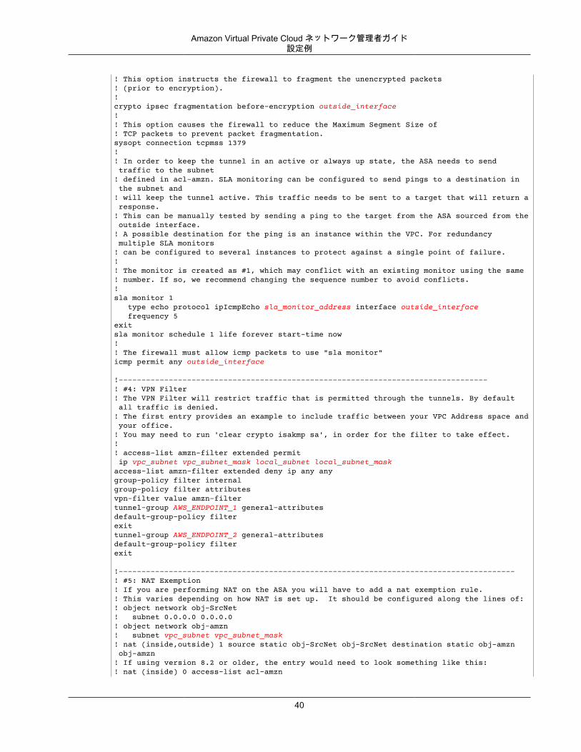
! This option instructs the firewall to fragment the unencrypted packets! (prior to encryption).!crypto ipsec fragmentation before-encryption outside_interface!! This option causes the firewall to reduce the Maximum Segment Size of! TCP packets to prevent packet fragmentation.sysopt connection tcpmss 1379!! In order to keep the tunnel in an active or always up state, the ASA needs to send traffic to the subnet! defined in acl-amzn. SLA monitoring can be configured to send pings to a destination in the subnet and! will keep the tunnel active. This traffic needs to be sent to a target that will return a response.! This can be manually tested by sending a ping to the target from the ASA sourced from the outside interface.! A possible destination for the ping is an instance within the VPC. For redundancy multiple SLA monitors ! can be configured to several instances to protect against a single point of failure.!! The monitor is created as #1, which may conflict with an existing monitor using the same! number. If so, we recommend changing the sequence number to avoid conflicts.!sla monitor 1 type echo protocol ipIcmpEcho sla_monitor_address interface outside_interface frequency 5exitsla monitor schedule 1 life forever start-time now!! The firewall must allow icmp packets to use "sla monitor"icmp permit any outside_interface
!---------------------------------------------------------------------------------! #4: VPN Filter! The VPN Filter will restrict traffic that is permitted through the tunnels. By default all traffic is denied. ! The first entry provides an example to include traffic between your VPC Address space and your office.! You may need to run 'clear crypto isakmp sa', in order for the filter to take effect.!! access-list amzn-filter extended permit ip vpc_subnet vpc_subnet_mask local_subnet local_subnet_maskaccess-list amzn-filter extended deny ip any anygroup-policy filter internalgroup-policy filter attributesvpn-filter value amzn-filtertunnel-group AWS_ENDPOINT_1 general-attributesdefault-group-policy filterexittunnel-group AWS_ENDPOINT_2 general-attributesdefault-group-policy filterexit
!---------------------------------------------------------------------------------------! #5: NAT Exemption! If you are performing NAT on the ASA you will have to add a nat exemption rule.! This varies depending on how NAT is set up. It should be configured along the lines of:! object network obj-SrcNet! subnet 0.0.0.0 0.0.0.0! object network obj-amzn! subnet vpc_subnet vpc_subnet_mask! nat (inside,outside) 1 source static obj-SrcNet obj-SrcNet destination static obj-amzn obj-amzn! If using version 8.2 or older, the entry would need to look something like this:! nat (inside) 0 access-list acl-amzn
40
Amazon Virtual Private Cloud ネットワーク管理者ガイドカスタマーゲートウェイ設定をテストする方法
! Or, the same rule in acl-amzn should be included in an existing no nat ACL.
カスタマーゲートウェイ設定をテストする方法Cisco ASA をカスタマーゲートウェイとして使用する場合、1 個のトンネルのみが起動状態になります。2番目のトンネルは、最初のトンネルが停止した場合のみ使用されますが、設定は必要です。1 番目のトンネルが起動状態であるときに、2 番目のトンネルを起動状態にすることはできません。コンソールには、1個のトンネルのみが起動しており、2 番目のトンネルがダウンしていることが示されます。これは、CiscoASA のカスタマーゲートウェイのトンネルでは予測される動作です。ASA では、カスタマーゲートウェイとして一度に 1 個のトンネルの起動のみがサポートされます。
各トンネルに対して、ゲートウェイ設定をテストすることができます。
各トンネルのカスタマーゲートウェイ設定をテストするには
• 静的ルートが VPN 接続に追加され、トラフィックがカスタマーゲートウェイに戻るようになっていることを確認します。たとえば、ローカルサブネットのプレフィックスが 198.10.0.0/16 の場合、その CIDR 範囲の静的ルートを VPN 接続に追加する必要があります。両方のトンネルに VPC への静的ルートがあることを確認します。
次に、VPC でインスタンスを起動し、ホームネットワークからインスタンスへの ping を実行して、各トンネルの接続をテストする必要があります。開始する前に、以下を確認してください。
• ping リクエストに応答する AMI を使用します。Amazon Linux AMI のいずれかを使用することをお勧めします。
• インスタンスのセキュリティグループとネットワーク ACL を設定し、インバウンド ICMP トラフィックを有効にします。
• VPN 接続用のルーティングを設定していることを確認します。サブネットのルートテーブルに仮想プライベートゲートウェイへのルートが含まれている必要があります。詳細については、Amazon VPC ユーザーガイド の「ルートテーブルでルート伝達を有効にする」を参照してください。
各トンネルのエンドツーエンド接続をテストするには
1. VPC で Amazon Linux AMI の 1 つのインスタンスを起動します。AWS マネジメントコンソールからインスタンスを起動すると、起動ウィザードのリストに Amazon Linux AMI が表示されます。詳細については、「Amazon VPC 入門ガイド」を参照してください。
2. インスタンスが実行中になった後、そのプライベート IP アドレス (例えば 10.0.0.4) を取得します。 コンソールにインスタンスの詳細の一部としてアドレスが表示されます。
3. ホームネットワークのシステムで、インスタンスの IP アドレスに対して ping コマンドを実行します。ping を実行するコンピューターがカスタマーゲートウェイの背後にないことを確認します。正常なレスポンスは次のようになります。
ping 10.0.0.4
Pinging 10.0.0.4 with 32 bytes of data:
Reply from 10.0.0.4: bytes=32 time<1ms TTL=128Reply from 10.0.0.4: bytes=32 time<1ms TTL=128Reply from 10.0.0.4: bytes=32 time<1ms TTL=128
Ping statistics for 10.0.0.4:Packets: Sent = 3, Received = 3, Lost = 0 (0% loss),
41
Amazon Virtual Private Cloud ネットワーク管理者ガイドカスタマーゲートウェイ設定をテストする方法
Approximate round trip times in milliseconds:Minimum = 0ms, Maximum = 0ms, Average = 0ms
Note
カスタマーゲートウェイルーターからインスタンスへの ping を実行する場合は、ping メッセージの送信元がトンネル IP アドレスではなく内部 IP アドレスになるようにしてください。一部の AMI は、トンネル IP アドレスからの ping メッセージに応答しません。
4. (オプション) トンネル フェイルオーバーをテストするため、カスタマーゲートウェイのトンネルの 1つを一時的に無効化し、上記の手順を繰り返すことができます。VPN 接続の AWS 側のトンネルを無効化することはできません。
トンネルのテストを正常に実施できない場合は、「Cisco ASA カスタマーゲートウェイの接続のトラブルシューティング (p. 176)」を参照してください。
42
Amazon Virtual Private Cloud ネットワーク管理者ガイドカスタマーゲートウェイの概要
例: Cisco ASA デバイスと仮想トンネルインターフェイス、およびボーダーゲートウェイプロトコル
トピック• カスタマーゲートウェイの概要 (p. 43)• 設定例 (p. 44)• カスタマーゲートウェイ設定をテストする方法 (p. 49)
このセクションでは、Cisco ASA 9.7.1+ ソフトウェアを実行している Cisco ASA デバイスをカスタマーゲートウェイとして使用する場合に、統合チームから提供される設定情報の例について説明します。
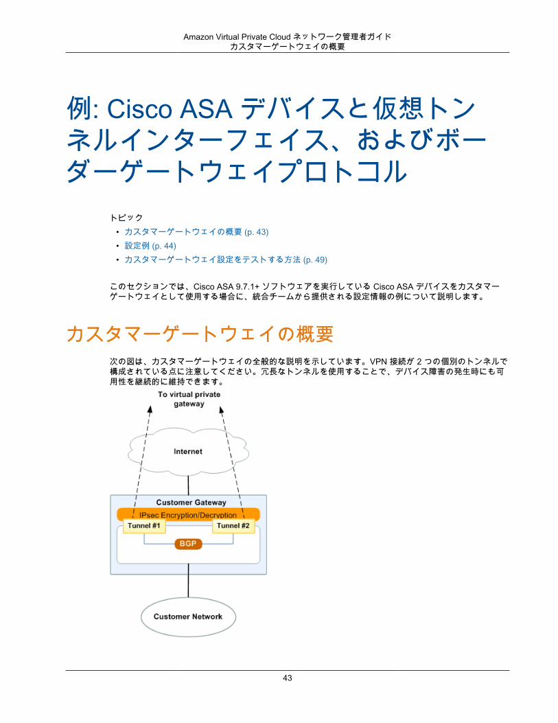
カスタマーゲートウェイの概要次の図は、カスタマーゲートウェイの全般的な説明を示しています。VPN 接続が 2 つの個別のトンネルで構成されている点に注意してください。冗長なトンネルを使用することで、デバイス障害の発生時にも可用性を継続的に維持できます。
43
Amazon Virtual Private Cloud ネットワーク管理者ガイド設定例
バージョン 9.7.1 以降の Cisco ASA は、アクティブ/アクティブモードをサポートします。これらの CiscoASA を使用する場合は、両方のトンネルを同時にアクティブにすることができます。この冗長化では、常にいずれかのトンネルを経由して VPC への接続を保持する必要があります。
設定例このセクションの設定は、統合チームから提供される設定情報の例です。この設定例には、各トンネルに設定する必要のある一連の情報が含まれています。
この設定例には、設定がどのように機能するかを理解するために役立つサンプル値が含まれています。たとえば、VPN 接続 ID (vpn-12345678)、仮想プライベートゲートウェイ ID (vgw-12345678)、AWS エンドポイントのプレースホルダー (AWS_ENDPOINT_1 および AWS_ENDPOINT_2) です。これらのサンプル値を、受け取った設定情報に含まれる実際の値で置き換えます。
また、以下を行う必要があります。
• 外部インターフェイスを設定します。• Crypto ISAKMP Policy Sequence の数値が一意であることを確認します。• Crypto IPsec Transform Set および Crypto ISAKMP Policy Sequence と、デバイスに設定された他のす
べての IPsec トンネルの整合性が確保されていることを確認します。• カスタマーゲートウェイとローカルネットワークとの間でトラフィックを動かす内部ルーティングをす
べて設定します。
Important
次の設定情報の例は、統合チームから提供されることが想定される内容です。この例に示された値の多くは、実際に受け取る設定情報とは異なります。ここに示されるサンプル値ではなく、実際の値を使用する必要があります。そうしないと、実装が失敗します。
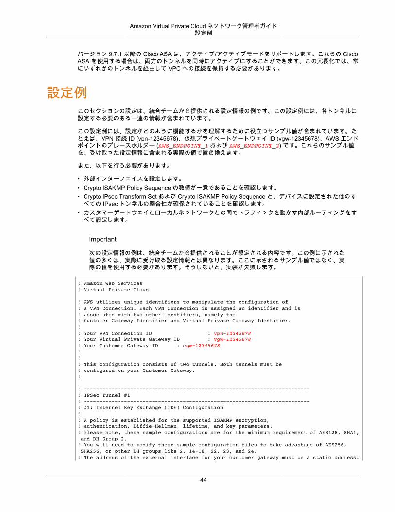
! Amazon Web Services! Virtual Private Cloud
! AWS utilizes unique identifiers to manipulate the configuration of! a VPN Connection. Each VPN Connection is assigned an identifier and is! associated with two other identifiers, namely the! Customer Gateway Identifier and Virtual Private Gateway Identifier.!! Your VPN Connection ID : vpn-12345678! Your Virtual Private Gateway ID : vgw-12345678! Your Customer Gateway ID : cgw-12345678!!! This configuration consists of two tunnels. Both tunnels must be! configured on your Customer Gateway.!
! -------------------------------------------------------------------------! IPSec Tunnel #1! -------------------------------------------------------------------------! #1: Internet Key Exchange (IKE) Configuration!! A policy is established for the supported ISAKMP encryption,! authentication, Diffie-Hellman, lifetime, and key parameters.! Please note, these sample configurations are for the minimum requirement of AES128, SHA1, and DH Group 2.! You will need to modify these sample configuration files to take advantage of AES256, SHA256, or other DH groups like 2, 14-18, 22, 23, and 24.! The address of the external interface for your customer gateway must be a static address.
44
Amazon Virtual Private Cloud ネットワーク管理者ガイド設定例
! Your customer gateway may reside behind a device performing network address translation (NAT).! To ensure that NAT traversal (NAT-T) can function, you must adjust your firewall !rules to unblock UDP port 4500. If not behind NAT, we recommend disabling NAT-T.!! Note that there are a global list of ISAKMP policies, each identified by! sequence number. This policy is defined as #200, which may conflict with! an existing policy using the same number. If so, we recommend changing! the sequence number to avoid conflicts.!
crypto ikev1 enable 'outside_interface'
crypto ikev1 policy 200 encryption aes authentication pre-share group 2 lifetime 28800 hash sha ! ------------------------------------------------------------------------- ! #2: IPSec Configuration!! The IPSec transform set defines the encryption, authentication, and IPSec! mode parameters.! Please note, you may use these additionally supported IPSec parameters for encryption like AES256 and other DH groups like 2, 5, 14-18, 22, 23, and 24.!crypto ipsec ikev1 transform-set ipsec-prop-vpn-12345678-0 esp-aes esp-sha-hmac
! The IPSec profile references the IPSec transform set and further defines! the Diffie-Hellman group and security association lifetime.!crypto ipsec profile ipsec-vpn-12345678-0 set pfs group2 set security-association lifetime seconds 3600 set ikev1 transform-set ipsec-prop-vpn-12345678-0exit
! Additional parameters of the IPSec configuration are set here. Note that! these parameters are global and therefore impact other IPSec! associations.! This option instructs the router to clear the "Don't Fragment"! bit from packets that carry this bit and yet must be fragmented, enabling! them to be fragmented. !!You will need to replace the outside_interface with the interface name of your ASA Firewall.
crypto ipsec df-bit clear-df 'outside_interface'
! This option causes the firewall to reduce the Maximum Segment Size of! TCP packets to prevent packet fragmentation.
sysopt connection tcpmss 1379
! This configures the gateway's window for accepting out of order! IPSec packets. A larger window can be helpful if too many packets! are dropped due to reordering while in transit between gateways.!crypto ipsec security-association replay window-size 128
45
Amazon Virtual Private Cloud ネットワーク管理者ガイド設定例
! This option instructs the router to fragment the unencrypted packets! (prior to encryption).!You will need to replace the outside_interface with the interface name of your ASA Firewall.!crypto ipsec fragmentation before-encryption 'outside_interface'
! -------------------------------------------------------------------------
! The tunnel group sets the Pre Shared Key used to authenticate the ! tunnel endpoints.!tunnel-group 13.54.43.86 type ipsec-l2ltunnel-group 13.54.43.86 ipsec-attributes ikev1 pre-shared-key pre-shared-key!! This option enables IPSec Dead Peer Detection, which causes semi-periodic! messages to be sent to ensure a Security Association remains operational.! isakmp keepalive threshold 10 retry 10exit
! -------------------------------------------------------------------------! #3: Tunnel Interface Configuration!! A tunnel interface is configured to be the logical interface associated! with the tunnel. All traffic routed to the tunnel interface will be! encrypted and transmitted to the VPC. Similarly, traffic from the VPC! will be logically received on this interface.!! Association with the IPSec security association is done through the! "tunnel protection" command.!! The address of the interface is configured with the setup for your! Customer Gateway. If the address changes, the Customer Gateway and VPN! Connection must be recreated with Amazon VPC.!!You will need to replace the outside_interface with the interface name of your ASA Firewall.
interface Tunnel1 nameif Tunnel-int-vpn-12345678-0 ip address 169.254.33.198 255.255.255.252 tunnel source interface 'outside_interface' tunnel destination 13.54.43.86 tunnel mode ipsec ipv4 tunnel protection ipsec profile ipsec-vpn-12345678-0 no shutdownexit
! -------------------------------------------------------------------------
! #4: Border Gateway Protocol (BGP) Configuration!! BGP is used within the tunnel to exchange prefixes between the! Virtual Private Gateway and your Customer Gateway. The Virtual Private Gateway! will announce the prefix corresponding to your VPC.!! Your Customer Gateway may announce a default route (0.0.0.0/0),! which can be done with the 'network' and 'default-originate' statements.!
46
Amazon Virtual Private Cloud ネットワーク管理者ガイド設定例
! The BGP timers are adjusted to provide more rapid detection of outages.!! The local BGP Autonomous System Number (ASN) (65343) is configured! as part of your Customer Gateway. If the ASN must be changed, the! Customer Gateway and VPN Connection will need to be recreated with AWS.!router bgp 65343 address-family ipv4 unicast neighbor 169.254.33.197 remote-as 7224 neighbor 169.254.33.197 timers 10 30 30 neighbor 169.254.33.197 default-originate neighbor 169.254.33.197 activate ! To advertise additional prefixes to Amazon VPC, copy the 'network' statement! and identify the prefix you wish to advertise. Make sure the prefix is present! in the routing table of the device with a valid next-hop. network 0.0.0.0 no auto-summaryno synchronization exit-address-familyexit!
! -------------------------------------------------------------------------! IPSec Tunnel #2! -------------------------------------------------------------------------! #1: Internet Key Exchange (IKE) Configuration!! A policy is established for the supported ISAKMP encryption,! authentication, Diffie-Hellman, lifetime, and key parameters.! Please note, these sample configurations are for the minimum requirement of AES128, SHA1, and DH Group 2.! You will need to modify these sample configuration files to take advantage of AES256, SHA256, or other DH groups like 2, 14-18, 22, 23, and 24.! The address of the external interface for your customer gateway must be a static address.! Your customer gateway may reside behind a device performing network address translation (NAT).! To ensure that NAT traversal (NAT-T) can function, you must adjust your firewall !rules to unblock UDP port 4500. If not behind NAT, we recommend disabling NAT-T.!! Note that there are a global list of ISAKMP policies, each identified by! sequence number. This policy is defined as #201, which may conflict with! an existing policy using the same number. If so, we recommend changing! the sequence number to avoid conflicts.!
crypto ikev1 enable 'outside_interface'
crypto ikev1 policy 201 encryption aes authentication pre-share group 2 lifetime 28800 hash sha ! ------------------------------------------------------------------------- ! #2: IPSec Configuration!! The IPSec transform set defines the encryption, authentication, and IPSec! mode parameters.! Please note, you may use these additionally supported IPSec parameters for encryption like AES256 and other DH groups like 2, 5, 14-18, 22, 23, and 24.!crypto ipsec ikev1 transform-set ipsec-prop-vpn-12345678-1 esp-aes esp-sha-hmac
47
Amazon Virtual Private Cloud ネットワーク管理者ガイド設定例
! The IPSec profile references the IPSec transform set and further defines! the Diffie-Hellman group and security association lifetime.!crypto ipsec profile ipsec-vpn-12345678-1 set pfs group2 set security-association lifetime seconds 3600 set ikev1 transform-set ipsec-prop-vpn-12345678-1exit
! Additional parameters of the IPSec configuration are set here. Note that! these parameters are global and therefore impact other IPSec! associations.! This option instructs the router to clear the "Don't Fragment"! bit from packets that carry this bit and yet must be fragmented, enabling! them to be fragmented. !!You will need to replace the outside_interface with the interface name of your ASA Firewall.
crypto ipsec df-bit clear-df 'outside_interface'
! This option causes the firewall to reduce the Maximum Segment Size of! TCP packets to prevent packet fragmentation.
sysopt connection tcpmss 1379
! This configures the gateway's window for accepting out of order! IPSec packets. A larger window can be helpful if too many packets! are dropped due to reordering while in transit between gateways.!crypto ipsec security-association replay window-size 128
! This option instructs the router to fragment the unencrypted packets! (prior to encryption).!You will need to replace the outside_interface with the interface name of your ASA Firewall.!crypto ipsec fragmentation before-encryption 'outside_interface'
! -------------------------------------------------------------------------
! The tunnel group sets the Pre Shared Key used to authenticate the ! tunnel endpoints.!tunnel-group 52.65.137.78 type ipsec-l2ltunnel-group 52.65.137.78 ipsec-attributes ikev1 pre-shared-key pre-shared-key!! This option enables IPSec Dead Peer Detection, which causes semi-periodic! messages to be sent to ensure a Security Association remains operational.! isakmp keepalive threshold 10 retry 10exit
! -------------------------------------------------------------------------! #3: Tunnel Interface Configuration!! A tunnel interface is configured to be the logical interface associated! with the tunnel. All traffic routed to the tunnel interface will be! encrypted and transmitted to the VPC. Similarly, traffic from the VPC
48
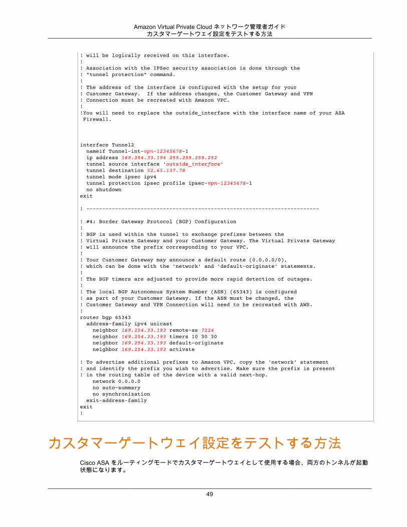
Amazon Virtual Private Cloud ネットワーク管理者ガイドカスタマーゲートウェイ設定をテストする方法
! will be logically received on this interface.!! Association with the IPSec security association is done through the! "tunnel protection" command.!! The address of the interface is configured with the setup for your! Customer Gateway. If the address changes, the Customer Gateway and VPN! Connection must be recreated with Amazon VPC.!!You will need to replace the outside_interface with the interface name of your ASA Firewall.
interface Tunnel2 nameif Tunnel-int-vpn-12345678-1 ip address 169.254.33.194 255.255.255.252 tunnel source interface 'outside_interface' tunnel destination 52.65.137.78 tunnel mode ipsec ipv4 tunnel protection ipsec profile ipsec-vpn-12345678-1 no shutdownexit
! -------------------------------------------------------------------------
! #4: Border Gateway Protocol (BGP) Configuration!! BGP is used within the tunnel to exchange prefixes between the! Virtual Private Gateway and your Customer Gateway. The Virtual Private Gateway! will announce the prefix corresponding to your VPC.!! Your Customer Gateway may announce a default route (0.0.0.0/0),! which can be done with the 'network' and 'default-originate' statements.!! The BGP timers are adjusted to provide more rapid detection of outages.!! The local BGP Autonomous System Number (ASN) (65343) is configured! as part of your Customer Gateway. If the ASN must be changed, the! Customer Gateway and VPN Connection will need to be recreated with AWS.!router bgp 65343 address-family ipv4 unicast neighbor 169.254.33.193 remote-as 7224 neighbor 169.254.33.193 timers 10 30 30 neighbor 169.254.33.193 default-originate neighbor 169.254.33.193 activate ! To advertise additional prefixes to Amazon VPC, copy the 'network' statement! and identify the prefix you wish to advertise. Make sure the prefix is present! in the routing table of the device with a valid next-hop. network 0.0.0.0 no auto-summary no synchronization exit-address-familyexit!
カスタマーゲートウェイ設定をテストする方法Cisco ASA をルーティングモードでカスタマーゲートウェイとして使用する場合、両方のトンネルが起動状態になります。
49
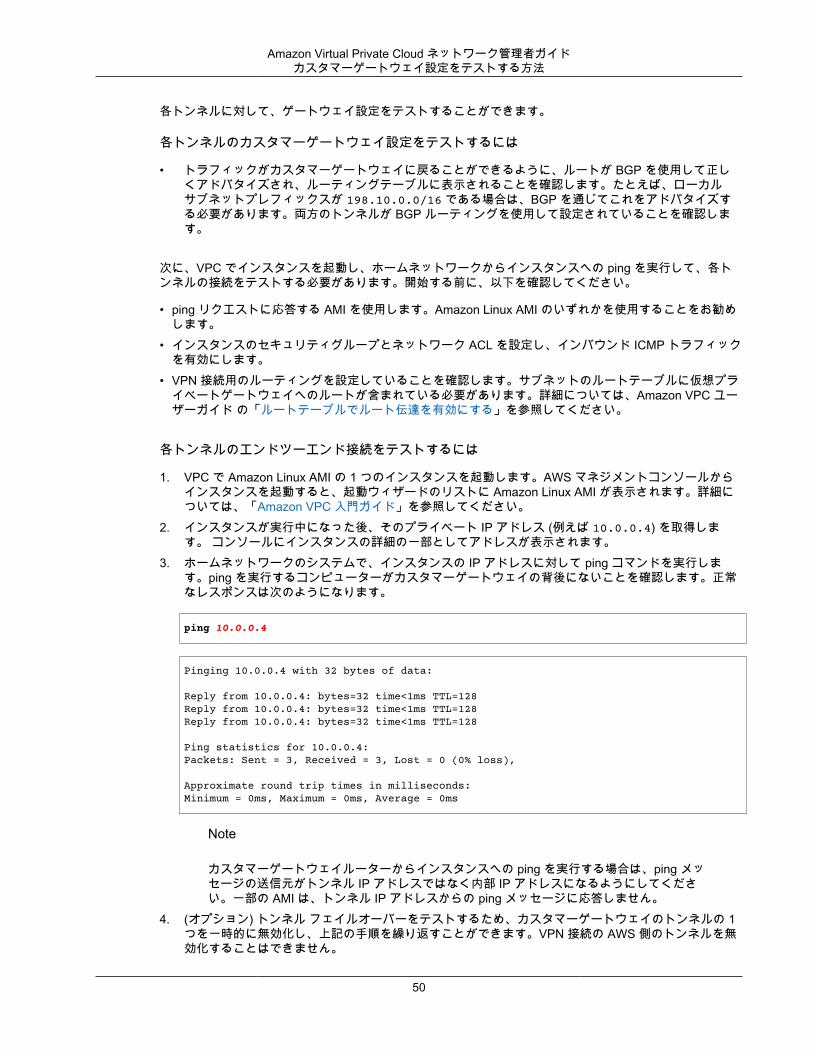
Amazon Virtual Private Cloud ネットワーク管理者ガイドカスタマーゲートウェイ設定をテストする方法
各トンネルに対して、ゲートウェイ設定をテストすることができます。
各トンネルのカスタマーゲートウェイ設定をテストするには
• トラフィックがカスタマーゲートウェイに戻ることができるように、ルートが BGP を使用して正しくアドバタイズされ、ルーティングテーブルに表示されることを確認します。たとえば、ローカルサブネットプレフィックスが 198.10.0.0/16 である場合は、BGP を通じてこれをアドバタイズする必要があります。両方のトンネルが BGP ルーティングを使用して設定されていることを確認します。
次に、VPC でインスタンスを起動し、ホームネットワークからインスタンスへの ping を実行して、各トンネルの接続をテストする必要があります。開始する前に、以下を確認してください。
• ping リクエストに応答する AMI を使用します。Amazon Linux AMI のいずれかを使用することをお勧めします。
• インスタンスのセキュリティグループとネットワーク ACL を設定し、インバウンド ICMP トラフィックを有効にします。
• VPN 接続用のルーティングを設定していることを確認します。サブネットのルートテーブルに仮想プライベートゲートウェイへのルートが含まれている必要があります。詳細については、Amazon VPC ユーザーガイド の「ルートテーブルでルート伝達を有効にする」を参照してください。
各トンネルのエンドツーエンド接続をテストするには
1. VPC で Amazon Linux AMI の 1 つのインスタンスを起動します。AWS マネジメントコンソールからインスタンスを起動すると、起動ウィザードのリストに Amazon Linux AMI が表示されます。詳細については、「Amazon VPC 入門ガイド」を参照してください。
2. インスタンスが実行中になった後、そのプライベート IP アドレス (例えば 10.0.0.4) を取得します。 コンソールにインスタンスの詳細の一部としてアドレスが表示されます。
3. ホームネットワークのシステムで、インスタンスの IP アドレスに対して ping コマンドを実行します。ping を実行するコンピューターがカスタマーゲートウェイの背後にないことを確認します。正常なレスポンスは次のようになります。
ping 10.0.0.4
Pinging 10.0.0.4 with 32 bytes of data:
Reply from 10.0.0.4: bytes=32 time<1ms TTL=128Reply from 10.0.0.4: bytes=32 time<1ms TTL=128Reply from 10.0.0.4: bytes=32 time<1ms TTL=128
Ping statistics for 10.0.0.4:Packets: Sent = 3, Received = 3, Lost = 0 (0% loss),
Approximate round trip times in milliseconds:Minimum = 0ms, Maximum = 0ms, Average = 0ms
Note
カスタマーゲートウェイルーターからインスタンスへの ping を実行する場合は、ping メッセージの送信元がトンネル IP アドレスではなく内部 IP アドレスになるようにしてください。一部の AMI は、トンネル IP アドレスからの ping メッセージに応答しません。
4. (オプション) トンネル フェイルオーバーをテストするため、カスタマーゲートウェイのトンネルの 1つを一時的に無効化し、上記の手順を繰り返すことができます。VPN 接続の AWS 側のトンネルを無効化することはできません。
50

Amazon Virtual Private Cloud ネットワーク管理者ガイドカスタマーゲートウェイ設定をテストする方法
トンネルのテストを正常に実施できない場合は、「Cisco ASA カスタマーゲートウェイの接続のトラブルシューティング (p. 176)」を参照してください。
51
Amazon Virtual Private Cloud ネットワーク管理者ガイドカスタマーゲートウェイの概要
例: Cisco ASA デバイスと仮想トンネルインターフェイス (ボーダーゲートウェイプロトコルなし)
トピック• カスタマーゲートウェイの概要 (p. 52)• 設定例 (p. 53)• カスタマーゲートウェイ設定をテストする方法 (p. 58)
このセクションでは、Cisco ASA 9.7.1 以降のソフトウェアを実行している Cisco ASA デバイスをカスタマーゲートウェイとして使用し、静的にルーティングされる VPN 接続を設定する場合に、統合チームから提供される設定情報の例について説明します。
カスタマーゲートウェイの概要次の図は、カスタマーゲートウェイの全般的な説明を示しています。VPN 接続が 2 つの個別のトンネルで構成されている点に注意してください。冗長なトンネルを使用することで、デバイス障害の発生時にも可用性を継続的に維持できます。
52
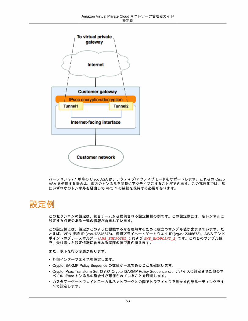
Amazon Virtual Private Cloud ネットワーク管理者ガイド設定例
バージョン 9.7.1 以降の Cisco ASA は、アクティブ/アクティブモードをサポートします。これらの CiscoASA を使用する場合は、両方のトンネルを同時にアクティブにすることができます。この冗長化では、常にいずれかのトンネルを経由して VPC への接続を保持する必要があります。
設定例このセクションの設定は、統合チームから提供される設定情報の例です。この設定例には、各トンネルに設定する必要のある一連の情報が含まれています。
この設定例には、設定がどのように機能するかを理解するために役立つサンプル値が含まれています。たとえば、VPN 接続 ID (vpn-12345678)、仮想プライベートゲートウェイ ID (vgw-12345678)、AWS エンドポイントのプレースホルダー (AWS_ENDPOINT_1 および AWS_ENDPOINT_2) です。これらのサンプル値を、受け取った設定情報に含まれる実際の値で置き換えます。
また、以下を行う必要があります。
• 外部インターフェイスを設定します。• Crypto ISAKMP Policy Sequence の数値が一意であることを確認します。• Crypto IPsec Transform Set および Crypto ISAKMP Policy Sequence と、デバイスに設定された他のす
べての IPsec トンネルの整合性が確保されていることを確認します。• カスタマーゲートウェイとローカルネットワークとの間でトラフィックを動かす内部ルーティングをす
べて設定します。
53
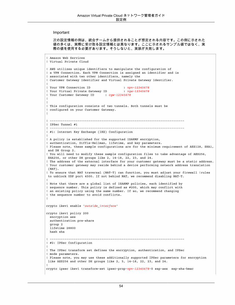
Amazon Virtual Private Cloud ネットワーク管理者ガイド設定例
Important
次の設定情報の例は、統合チームから提供されることが想定される内容です。この例に示された値の多くは、実際に受け取る設定情報とは異なります。ここに示されるサンプル値ではなく、実際の値を使用する必要があります。そうしないと、実装が失敗します。
! Amazon Web Services! Virtual Private Cloud
! AWS utilizes unique identifiers to manipulate the configuration of! a VPN Connection. Each VPN Connection is assigned an identifier and is! associated with two other identifiers, namely the! Customer Gateway Identifier and Virtual Private Gateway Identifier.!! Your VPN Connection ID : vpn-12345678! Your Virtual Private Gateway ID : vgw-12345678! Your Customer Gateway ID : cgw-12345678!!! This configuration consists of two tunnels. Both tunnels must be! configured on your Customer Gateway.!
! -------------------------------------------------------------------------! IPSec Tunnel #1! -------------------------------------------------------------------------! #1: Internet Key Exchange (IKE) Configuration!! A policy is established for the supported ISAKMP encryption,! authentication, Diffie-Hellman, lifetime, and key parameters.! Please note, these sample configurations are for the minimum requirement of AES128, SHA1, and DH Group 2.! You will need to modify these sample configuration files to take advantage of AES256, SHA256, or other DH groups like 2, 14-18, 22, 23, and 24.! The address of the external interface for your customer gateway must be a static address.! Your customer gateway may reside behind a device performing network address translation (NAT).! To ensure that NAT traversal (NAT-T) can function, you must adjust your firewall !rules to unblock UDP port 4500. If not behind NAT, we recommend disabling NAT-T.!! Note that there are a global list of ISAKMP policies, each identified by! sequence number. This policy is defined as #200, which may conflict with! an existing policy using the same number. If so, we recommend changing! the sequence number to avoid conflicts.!
crypto ikev1 enable 'outside_interface'
crypto ikev1 policy 200 encryption aes authentication pre-share group 2 lifetime 28800 hash sha ! ------------------------------------------------------------------------- ! #2: IPSec Configuration!! The IPSec transform set defines the encryption, authentication, and IPSec! mode parameters.! Please note, you may use these additionally supported IPSec parameters for encryption like AES256 and other DH groups like 2, 5, 14-18, 22, 23, and 24.!crypto ipsec ikev1 transform-set ipsec-prop-vpn-12345678-0 esp-aes esp-sha-hmac
54
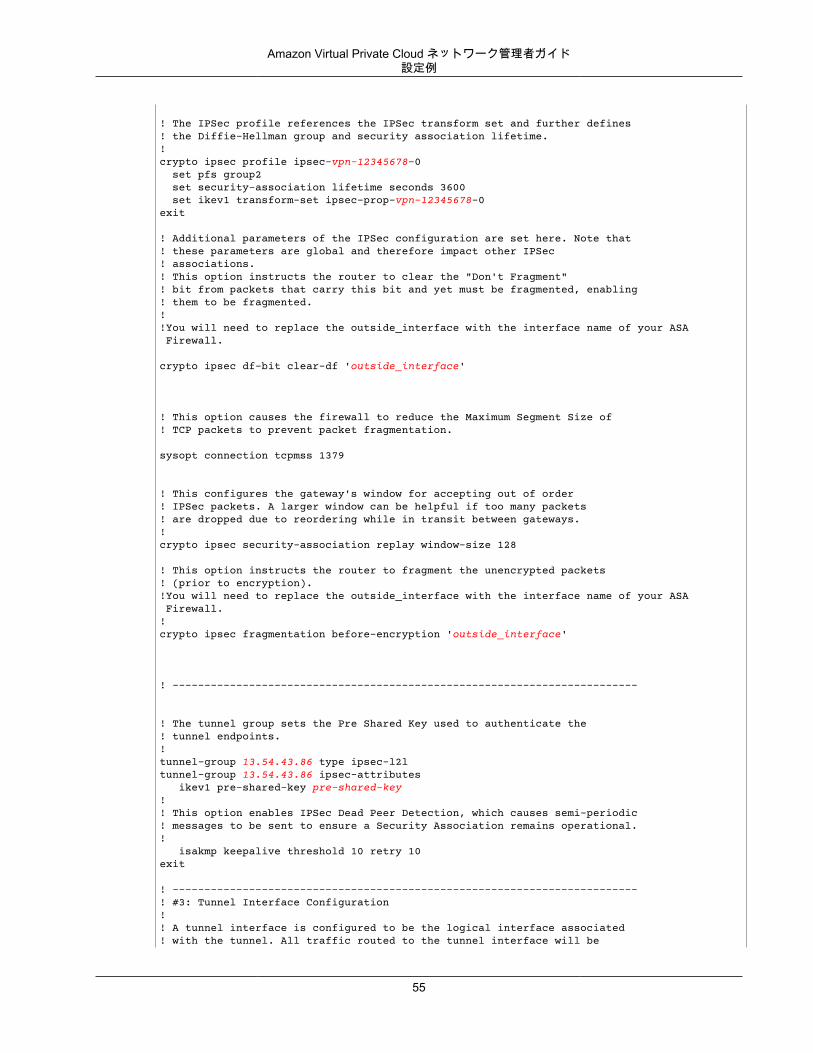
Amazon Virtual Private Cloud ネットワーク管理者ガイド設定例
! The IPSec profile references the IPSec transform set and further defines! the Diffie-Hellman group and security association lifetime.!crypto ipsec profile ipsec-vpn-12345678-0 set pfs group2 set security-association lifetime seconds 3600 set ikev1 transform-set ipsec-prop-vpn-12345678-0exit
! Additional parameters of the IPSec configuration are set here. Note that! these parameters are global and therefore impact other IPSec! associations.! This option instructs the router to clear the "Don't Fragment"! bit from packets that carry this bit and yet must be fragmented, enabling! them to be fragmented. !!You will need to replace the outside_interface with the interface name of your ASA Firewall.
crypto ipsec df-bit clear-df 'outside_interface'
! This option causes the firewall to reduce the Maximum Segment Size of! TCP packets to prevent packet fragmentation.
sysopt connection tcpmss 1379
! This configures the gateway's window for accepting out of order! IPSec packets. A larger window can be helpful if too many packets! are dropped due to reordering while in transit between gateways.!crypto ipsec security-association replay window-size 128
! This option instructs the router to fragment the unencrypted packets! (prior to encryption).!You will need to replace the outside_interface with the interface name of your ASA Firewall.!crypto ipsec fragmentation before-encryption 'outside_interface'
! -------------------------------------------------------------------------
! The tunnel group sets the Pre Shared Key used to authenticate the ! tunnel endpoints.!tunnel-group 13.54.43.86 type ipsec-l2ltunnel-group 13.54.43.86 ipsec-attributes ikev1 pre-shared-key pre-shared-key!! This option enables IPSec Dead Peer Detection, which causes semi-periodic! messages to be sent to ensure a Security Association remains operational.! isakmp keepalive threshold 10 retry 10exit
! -------------------------------------------------------------------------! #3: Tunnel Interface Configuration!! A tunnel interface is configured to be the logical interface associated! with the tunnel. All traffic routed to the tunnel interface will be
55
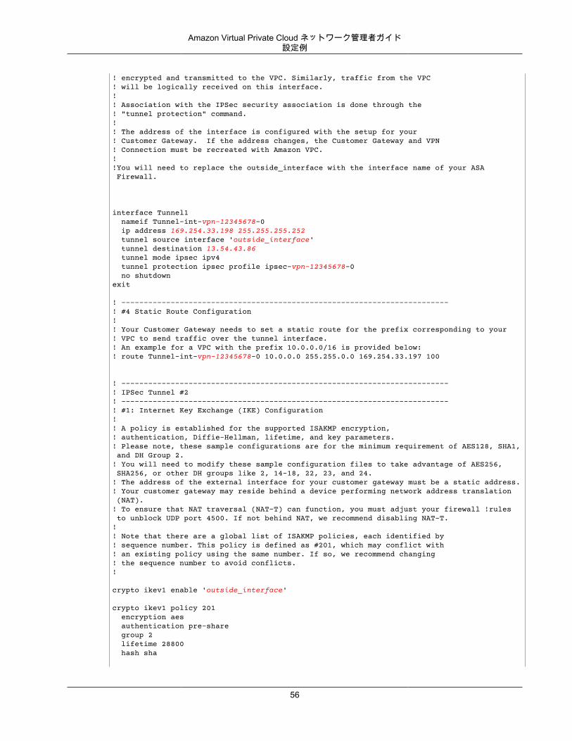
Amazon Virtual Private Cloud ネットワーク管理者ガイド設定例
! encrypted and transmitted to the VPC. Similarly, traffic from the VPC! will be logically received on this interface.!! Association with the IPSec security association is done through the! "tunnel protection" command.!! The address of the interface is configured with the setup for your! Customer Gateway. If the address changes, the Customer Gateway and VPN! Connection must be recreated with Amazon VPC.!!You will need to replace the outside_interface with the interface name of your ASA Firewall.
interface Tunnel1 nameif Tunnel-int-vpn-12345678-0 ip address 169.254.33.198 255.255.255.252 tunnel source interface 'outside_interface' tunnel destination 13.54.43.86 tunnel mode ipsec ipv4 tunnel protection ipsec profile ipsec-vpn-12345678-0 no shutdownexit
! -------------------------------------------------------------------------! #4 Static Route Configuration!! Your Customer Gateway needs to set a static route for the prefix corresponding to your! VPC to send traffic over the tunnel interface.! An example for a VPC with the prefix 10.0.0.0/16 is provided below:! route Tunnel-int-vpn-12345678-0 10.0.0.0 255.255.0.0 169.254.33.197 100 ! -------------------------------------------------------------------------! IPSec Tunnel #2! -------------------------------------------------------------------------! #1: Internet Key Exchange (IKE) Configuration!! A policy is established for the supported ISAKMP encryption,! authentication, Diffie-Hellman, lifetime, and key parameters.! Please note, these sample configurations are for the minimum requirement of AES128, SHA1, and DH Group 2.! You will need to modify these sample configuration files to take advantage of AES256, SHA256, or other DH groups like 2, 14-18, 22, 23, and 24.! The address of the external interface for your customer gateway must be a static address.! Your customer gateway may reside behind a device performing network address translation (NAT).! To ensure that NAT traversal (NAT-T) can function, you must adjust your firewall !rules to unblock UDP port 4500. If not behind NAT, we recommend disabling NAT-T.!! Note that there are a global list of ISAKMP policies, each identified by! sequence number. This policy is defined as #201, which may conflict with! an existing policy using the same number. If so, we recommend changing! the sequence number to avoid conflicts.!
crypto ikev1 enable 'outside_interface'
crypto ikev1 policy 201 encryption aes authentication pre-share group 2 lifetime 28800 hash sha
56
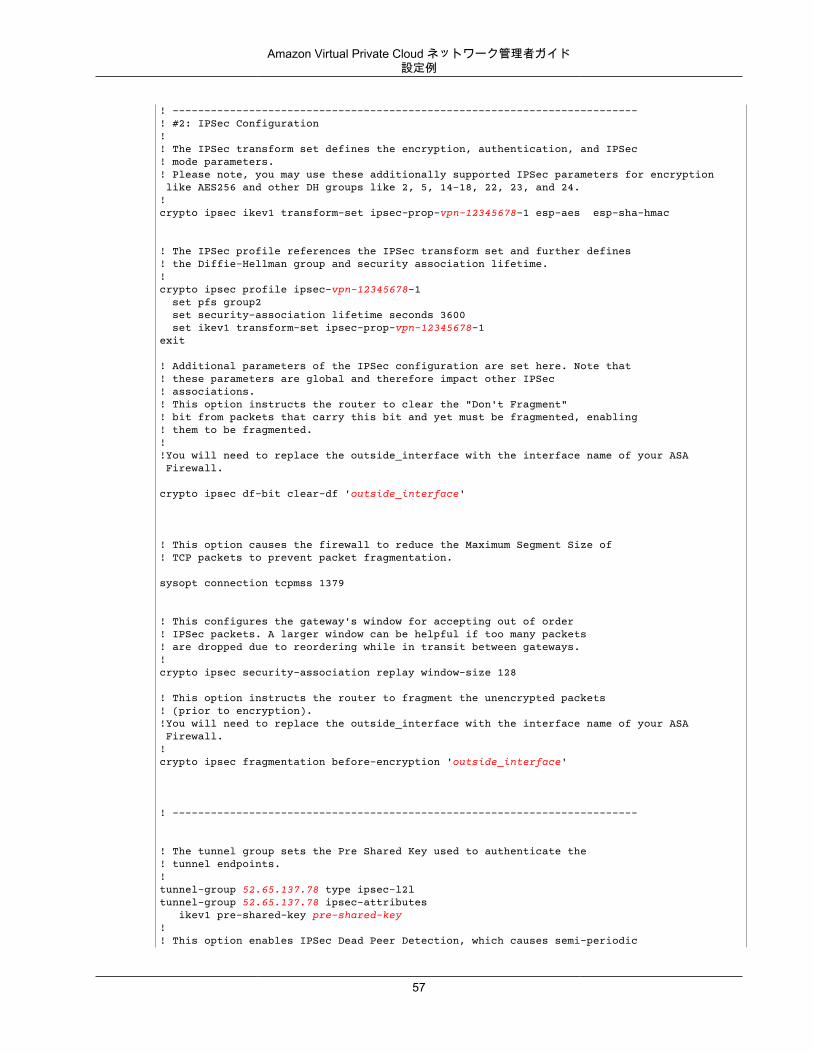
Amazon Virtual Private Cloud ネットワーク管理者ガイド設定例
! ------------------------------------------------------------------------- ! #2: IPSec Configuration!! The IPSec transform set defines the encryption, authentication, and IPSec! mode parameters.! Please note, you may use these additionally supported IPSec parameters for encryption like AES256 and other DH groups like 2, 5, 14-18, 22, 23, and 24.!crypto ipsec ikev1 transform-set ipsec-prop-vpn-12345678-1 esp-aes esp-sha-hmac
! The IPSec profile references the IPSec transform set and further defines! the Diffie-Hellman group and security association lifetime.!crypto ipsec profile ipsec-vpn-12345678-1 set pfs group2 set security-association lifetime seconds 3600 set ikev1 transform-set ipsec-prop-vpn-12345678-1exit
! Additional parameters of the IPSec configuration are set here. Note that! these parameters are global and therefore impact other IPSec! associations.! This option instructs the router to clear the "Don't Fragment"! bit from packets that carry this bit and yet must be fragmented, enabling! them to be fragmented. !!You will need to replace the outside_interface with the interface name of your ASA Firewall.
crypto ipsec df-bit clear-df 'outside_interface'
! This option causes the firewall to reduce the Maximum Segment Size of! TCP packets to prevent packet fragmentation.
sysopt connection tcpmss 1379
! This configures the gateway's window for accepting out of order! IPSec packets. A larger window can be helpful if too many packets! are dropped due to reordering while in transit between gateways.!crypto ipsec security-association replay window-size 128
! This option instructs the router to fragment the unencrypted packets! (prior to encryption).!You will need to replace the outside_interface with the interface name of your ASA Firewall.!crypto ipsec fragmentation before-encryption 'outside_interface'
! -------------------------------------------------------------------------
! The tunnel group sets the Pre Shared Key used to authenticate the ! tunnel endpoints.!tunnel-group 52.65.137.78 type ipsec-l2ltunnel-group 52.65.137.78 ipsec-attributes ikev1 pre-shared-key pre-shared-key!! This option enables IPSec Dead Peer Detection, which causes semi-periodic
57
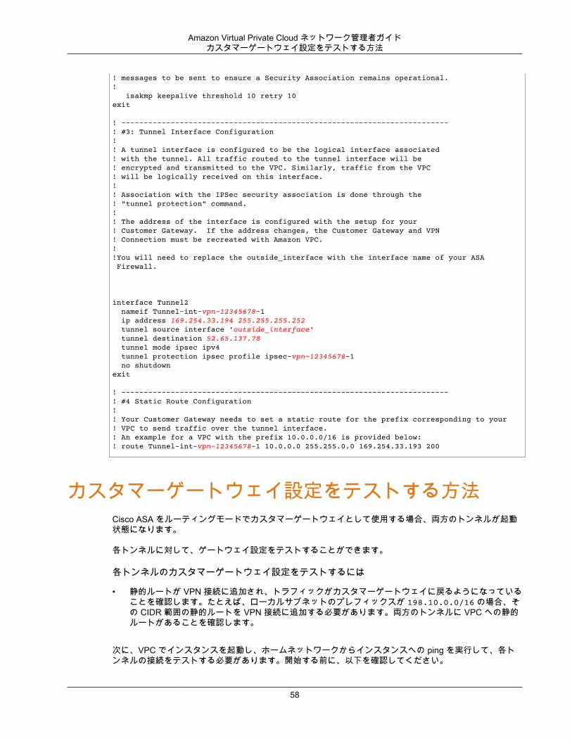
Amazon Virtual Private Cloud ネットワーク管理者ガイドカスタマーゲートウェイ設定をテストする方法
! messages to be sent to ensure a Security Association remains operational.! isakmp keepalive threshold 10 retry 10exit
! -------------------------------------------------------------------------! #3: Tunnel Interface Configuration!! A tunnel interface is configured to be the logical interface associated! with the tunnel. All traffic routed to the tunnel interface will be! encrypted and transmitted to the VPC. Similarly, traffic from the VPC! will be logically received on this interface.!! Association with the IPSec security association is done through the! "tunnel protection" command.!! The address of the interface is configured with the setup for your! Customer Gateway. If the address changes, the Customer Gateway and VPN! Connection must be recreated with Amazon VPC.!!You will need to replace the outside_interface with the interface name of your ASA Firewall.
interface Tunnel2 nameif Tunnel-int-vpn-12345678-1 ip address 169.254.33.194 255.255.255.252 tunnel source interface 'outside_interface' tunnel destination 52.65.137.78 tunnel mode ipsec ipv4 tunnel protection ipsec profile ipsec-vpn-12345678-1 no shutdownexit
! -------------------------------------------------------------------------! #4 Static Route Configuration!! Your Customer Gateway needs to set a static route for the prefix corresponding to your! VPC to send traffic over the tunnel interface.! An example for a VPC with the prefix 10.0.0.0/16 is provided below:! route Tunnel-int-vpn-12345678-1 10.0.0.0 255.255.0.0 169.254.33.193 200
カスタマーゲートウェイ設定をテストする方法Cisco ASA をルーティングモードでカスタマーゲートウェイとして使用する場合、両方のトンネルが起動状態になります。
各トンネルに対して、ゲートウェイ設定をテストすることができます。
各トンネルのカスタマーゲートウェイ設定をテストするには
• 静的ルートが VPN 接続に追加され、トラフィックがカスタマーゲートウェイに戻るようになっていることを確認します。たとえば、ローカルサブネットのプレフィックスが 198.10.0.0/16 の場合、その CIDR 範囲の静的ルートを VPN 接続に追加する必要があります。両方のトンネルに VPC への静的ルートがあることを確認します。
次に、VPC でインスタンスを起動し、ホームネットワークからインスタンスへの ping を実行して、各トンネルの接続をテストする必要があります。開始する前に、以下を確認してください。
58

Amazon Virtual Private Cloud ネットワーク管理者ガイドカスタマーゲートウェイ設定をテストする方法
• ping リクエストに応答する AMI を使用します。Amazon Linux AMI のいずれかを使用することをお勧めします。
• インスタンスのセキュリティグループとネットワーク ACL を設定し、インバウンド ICMP トラフィックを有効にします。
• VPN 接続用のルーティングを設定していることを確認します。サブネットのルートテーブルに仮想プライベートゲートウェイへのルートが含まれている必要があります。詳細については、Amazon VPC ユーザーガイド の「ルートテーブルでルート伝達を有効にする」を参照してください。
各トンネルのエンドツーエンド接続をテストするには
1. VPC で Amazon Linux AMI の 1 つのインスタンスを起動します。AWS マネジメントコンソールからインスタンスを起動すると、起動ウィザードのリストに Amazon Linux AMI が表示されます。詳細については、「Amazon VPC 入門ガイド」を参照してください。
2. インスタンスが実行中になった後、そのプライベート IP アドレス (例えば 10.0.0.4) を取得します。 コンソールにインスタンスの詳細の一部としてアドレスが表示されます。
3. ホームネットワークのシステムで、インスタンスの IP アドレスに対して ping コマンドを実行します。ping を実行するコンピューターがカスタマーゲートウェイの背後にないことを確認します。正常なレスポンスは次のようになります。
ping 10.0.0.4
Pinging 10.0.0.4 with 32 bytes of data:
Reply from 10.0.0.4: bytes=32 time<1ms TTL=128Reply from 10.0.0.4: bytes=32 time<1ms TTL=128Reply from 10.0.0.4: bytes=32 time<1ms TTL=128
Ping statistics for 10.0.0.4:Packets: Sent = 3, Received = 3, Lost = 0 (0% loss),
Approximate round trip times in milliseconds:Minimum = 0ms, Maximum = 0ms, Average = 0ms
Note
カスタマーゲートウェイルーターからインスタンスへの ping を実行する場合は、ping メッセージの送信元がトンネル IP アドレスではなく内部 IP アドレスになるようにしてください。一部の AMI は、トンネル IP アドレスからの ping メッセージに応答しません。
4. (オプション) トンネル フェイルオーバーをテストするため、カスタマーゲートウェイのトンネルの 1つを一時的に無効化し、上記の手順を繰り返すことができます。VPN 接続の AWS 側のトンネルを無効化することはできません。
トンネルのテストを正常に実施できない場合は、「Cisco ASA カスタマーゲートウェイの接続のトラブルシューティング (p. 176)」を参照してください。
59
Amazon Virtual Private Cloud ネットワーク管理者ガイド
例: Cisco IOS デバイストピック
• カスタマーゲートウェイの概要 (p. 61)• カスタマーゲートウェイの詳細と設定例 (p. 62)• カスタマーゲートウェイ設定をテストする方法 (p. 68)
このセクションでは、Cisco IOS 12.4 (またはそれ以降の) ソフトウェアを実行している Cisco IOS デバイスをカスタマーゲートウェイとして使用する場合に、統合チームから提供される設定情報の例について説明します。
2 つの図で設定例を紹介します。最初の図はカスタマーゲートウェイのレイアウトの概要を表し、2 番目の図はこの設定例の詳細を表しています。統合チームから受け取った実際の設定情報を使用して、カスタマーゲートウェイに適用する必要があります。
60
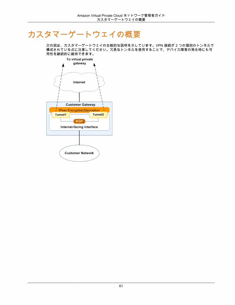
Amazon Virtual Private Cloud ネットワーク管理者ガイドカスタマーゲートウェイの概要
カスタマーゲートウェイの概要次の図は、カスタマーゲートウェイの全般的な説明を示しています。VPN 接続が 2 つの個別のトンネルで構成されている点に注意してください。冗長なトンネルを使用することで、デバイス障害の発生時にも可用性を継続的に維持できます。
61
Amazon Virtual Private Cloud ネットワーク管理者ガイドカスタマーゲートウェイの詳細と設定例
カスタマーゲートウェイの詳細と設定例このセクションの図は、Cisco IOS のカスタマーゲートウェイの例を示しています。図の後には、統合チームから提供される設定情報の対応する例が示されています。この設定例には、各トンネルに設定する必要のある一連の情報が含まれています。
さらに、指定する必要ある以下の項目が示されています。
• YOUR_UPLINK_ADDRESS—カスタマーゲートウェイ上のインターネットルーティングが可能な外部インターフェイスの IP アドレス。このアドレスは静的である必要があります。また、ネットワークアドレス変換 (NAT) を実行するデバイスの背後のアドレスを使用することができます。NAT トラバーサル (NAT-T) を正しく機能させるには、UDP ポート 4500 のブロックを解除するようにファイアウォールのルールを調整する必要があります。
• YOUR_BGP_ASN - カスタマーゲートウェイの BGP ASN (デフォルトで 65000 を使用します)
この設定例には、設定がどのように機能するかを理解するために役立つサンプル値が含まれています。たとえば、VPN 接続 ID (vpn-44a8938f)、仮想プライベートゲートウェイ ID (vgw-8db04f81)、IP アドレス(72.21.209.*, 169.254.255.*)、リモート ASN (7224) です。これらのサンプル値を、受け取った設定情報に含まれる実際の値で置き換えます。
さらに、以下を実行する必要があります。
• 外部インターフェイスを設定します。• トンネルインターフェイス ID を設定します (設定例では Tunnel1 および Tunnel2 と示されていま
す)。• Crypto ISAKMP Policy Sequence の数値が一意であることを確認します。• Crypto IPsec Transform Set および Crypto ISAKMP Policy Sequence と、デバイスに設定された他のす
べての IPsec トンネルの整合性が確保されていることを確認します。• カスタマーゲートウェイとローカルネットワークとの間でトラフィックを動かす内部ルーティングをす
べて設定します。
次の図および設定例では、イタリックの赤い文字の項目を、特定の設定に適用される値で置き換える必要があります。
62
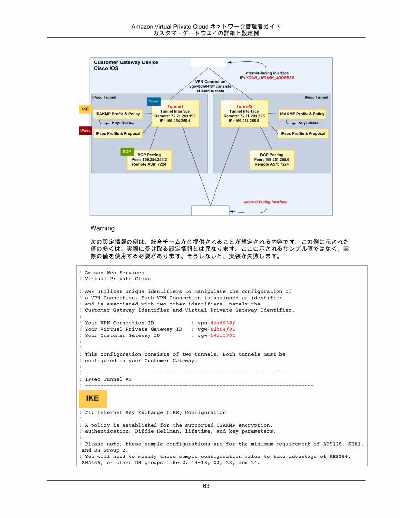
Amazon Virtual Private Cloud ネットワーク管理者ガイドカスタマーゲートウェイの詳細と設定例
Warning
次の設定情報の例は、統合チームから提供されることが想定される内容です。この例に示された値の多くは、実際に受け取る設定情報とは異なります。ここに示されるサンプル値ではなく、実際の値を使用する必要があります。そうしないと、実装が失敗します。
! Amazon Web Services! Virtual Private Cloud
! AWS utilizes unique identifiers to manipulate the configuration of ! a VPN Connection. Each VPN Connection is assigned an identifier ! and is associated with two other identifiers, namely the ! Customer Gateway Identifier and Virtual Private Gateway Identifier.!! Your VPN Connection ID : vpn-44a8938f! Your Virtual Private Gateway ID : vgw-8db04f81! Your Customer Gateway ID : cgw-b4dc3961!!! This configuration consists of two tunnels. Both tunnels must be ! configured on your Customer Gateway.!! -------------------------------------------------------------------------! IPsec Tunnel #1! -------------------------------------------------------------------------
! #1: Internet Key Exchange (IKE) Configuration!! A policy is established for the supported ISAKMP encryption, ! authentication, Diffie-Hellman, lifetime, and key parameters.!! Please note, these sample configurations are for the minimum requirement of AES128, SHA1, and DH Group 2.! You will need to modify these sample configuration files to take advantage of AES256, SHA256, or other DH groups like 2, 14-18, 22, 23, and 24.
63
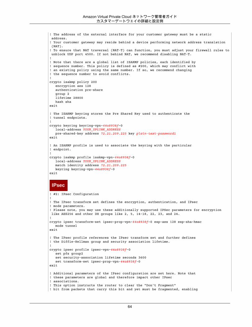
Amazon Virtual Private Cloud ネットワーク管理者ガイドカスタマーゲートウェイの詳細と設定例
! The address of the external interface for your customer gateway must be a static address. ! Your customer gateway may reside behind a device performing network address translation (NAT).! To ensure that NAT traversal (NAT-T) can function, you must adjust your firewall rules to unblock UDP port 4500. If not behind NAT, we recommend disabling NAT-T.!! Note that there are a global list of ISAKMP policies, each identified by ! sequence number. This policy is defined as #200, which may conflict with! an existing policy using the same number. If so, we recommend changing ! the sequence number to avoid conflicts.!crypto isakmp policy 200 encryption aes 128 authentication pre-share group 2 lifetime 28800 hash shaexit
! The ISAKMP keyring stores the Pre Shared Key used to authenticate the ! tunnel endpoints.!crypto keyring keyring-vpn-44a8938f-0 local-address YOUR_UPLINK_ADDRESS pre-shared-key address 72.21.209.225 key plain-text-password1exit
! An ISAKMP profile is used to associate the keyring with the particular ! endpoint.!crypto isakmp profile isakmp-vpn-44a8938f-0 local-address YOUR_UPLINK_ADDRESS match identity address 72.21.209.225 keyring keyring-vpn-44a8938f-0exit
! #2: IPsec Configuration! ! The IPsec transform set defines the encryption, authentication, and IPsec! mode parameters.! Please note, you may use these additionally supported IPSec parameters for encryption like AES256 and other DH groups like 2, 5, 14-18, 22, 23, and 24.!crypto ipsec transform-set ipsec-prop-vpn-44a8938f-0 esp-aes 128 esp-sha-hmac mode tunnelexit
! The IPsec profile references the IPsec transform set and further defines! the Diffie-Hellman group and security association lifetime.!crypto ipsec profile ipsec-vpn-44a8938f-0 set pfs group2 set security-association lifetime seconds 3600 set transform-set ipsec-prop-vpn-44a8938f-0exit
! Additional parameters of the IPsec configuration are set here. Note that ! these parameters are global and therefore impact other IPsec ! associations.! This option instructs the router to clear the "Don't Fragment" ! bit from packets that carry this bit and yet must be fragmented, enabling
64
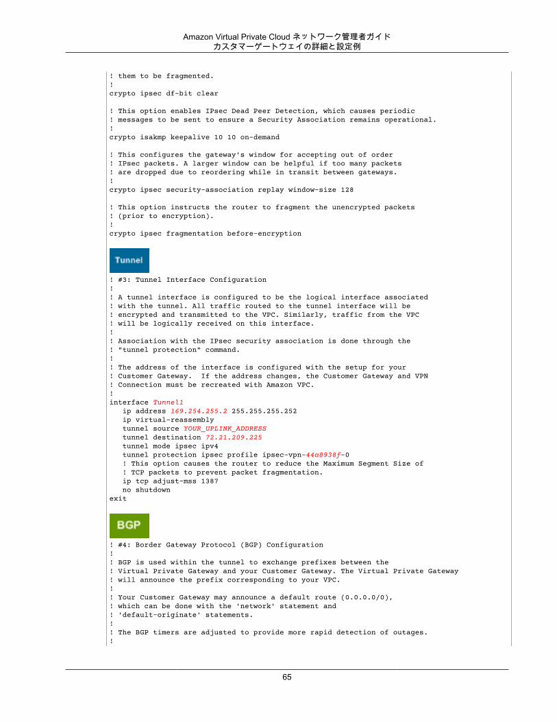
Amazon Virtual Private Cloud ネットワーク管理者ガイドカスタマーゲートウェイの詳細と設定例
! them to be fragmented.!crypto ipsec df-bit clear
! This option enables IPsec Dead Peer Detection, which causes periodic! messages to be sent to ensure a Security Association remains operational.!crypto isakmp keepalive 10 10 on-demand
! This configures the gateway's window for accepting out of order! IPsec packets. A larger window can be helpful if too many packets ! are dropped due to reordering while in transit between gateways.!crypto ipsec security-association replay window-size 128
! This option instructs the router to fragment the unencrypted packets! (prior to encryption).!crypto ipsec fragmentation before-encryption
! #3: Tunnel Interface Configuration! ! A tunnel interface is configured to be the logical interface associated ! with the tunnel. All traffic routed to the tunnel interface will be ! encrypted and transmitted to the VPC. Similarly, traffic from the VPC! will be logically received on this interface.!! Association with the IPsec security association is done through the ! "tunnel protection" command.!! The address of the interface is configured with the setup for your ! Customer Gateway. If the address changes, the Customer Gateway and VPN ! Connection must be recreated with Amazon VPC.!interface Tunnel1 ip address 169.254.255.2 255.255.255.252 ip virtual-reassembly tunnel source YOUR_UPLINK_ADDRESS tunnel destination 72.21.209.225 tunnel mode ipsec ipv4 tunnel protection ipsec profile ipsec-vpn-44a8938f-0 ! This option causes the router to reduce the Maximum Segment Size of ! TCP packets to prevent packet fragmentation. ip tcp adjust-mss 1387 no shutdownexit
! #4: Border Gateway Protocol (BGP) Configuration! ! BGP is used within the tunnel to exchange prefixes between the! Virtual Private Gateway and your Customer Gateway. The Virtual Private Gateway ! will announce the prefix corresponding to your VPC.! ! Your Customer Gateway may announce a default route (0.0.0.0/0), ! which can be done with the 'network' statement and ! 'default-originate' statements. !! The BGP timers are adjusted to provide more rapid detection of outages.!
65
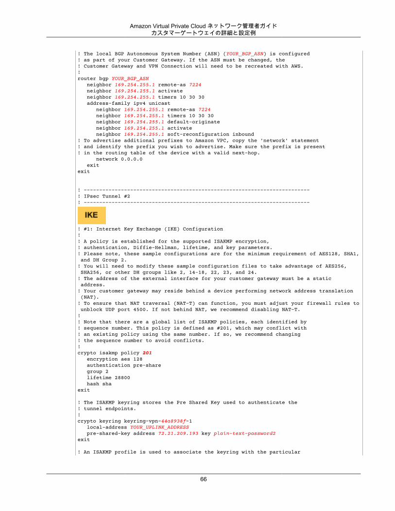
Amazon Virtual Private Cloud ネットワーク管理者ガイドカスタマーゲートウェイの詳細と設定例
! The local BGP Autonomous System Number (ASN) (YOUR_BGP_ASN) is configured! as part of your Customer Gateway. If the ASN must be changed, the ! Customer Gateway and VPN Connection will need to be recreated with AWS.! router bgp YOUR_BGP_ASN neighbor 169.254.255.1 remote-as 7224 neighbor 169.254.255.1 activate neighbor 169.254.255.1 timers 10 30 30 address-family ipv4 unicast neighbor 169.254.255.1 remote-as 7224 neighbor 169.254.255.1 timers 10 30 30 neighbor 169.254.255.1 default-originate neighbor 169.254.255.1 activate neighbor 169.254.255.1 soft-reconfiguration inbound! To advertise additional prefixes to Amazon VPC, copy the 'network' statement! and identify the prefix you wish to advertise. Make sure the prefix is present! in the routing table of the device with a valid next-hop. network 0.0.0.0 exitexit
! -------------------------------------------------------------------------! IPsec Tunnel #2! -------------------------------------------------------------------------
! #1: Internet Key Exchange (IKE) Configuration!! A policy is established for the supported ISAKMP encryption, ! authentication, Diffie-Hellman, lifetime, and key parameters.! Please note, these sample configurations are for the minimum requirement of AES128, SHA1, and DH Group 2.! You will need to modify these sample configuration files to take advantage of AES256, SHA256, or other DH groups like 2, 14-18, 22, 23, and 24.! The address of the external interface for your customer gateway must be a static address. ! Your customer gateway may reside behind a device performing network address translation (NAT).! To ensure that NAT traversal (NAT-T) can function, you must adjust your firewall rules to unblock UDP port 4500. If not behind NAT, we recommend disabling NAT-T.!! Note that there are a global list of ISAKMP policies, each identified by ! sequence number. This policy is defined as #201, which may conflict with! an existing policy using the same number. If so, we recommend changing ! the sequence number to avoid conflicts.!crypto isakmp policy 201 encryption aes 128 authentication pre-share group 2 lifetime 28800 hash shaexit
! The ISAKMP keyring stores the Pre Shared Key used to authenticate the ! tunnel endpoints.!crypto keyring keyring-vpn-44a8938f-1 local-address YOUR_UPLINK_ADDRESS pre-shared-key address 72.21.209.193 key plain-text-password2exit
! An ISAKMP profile is used to associate the keyring with the particular
66
Amazon Virtual Private Cloud ネットワーク管理者ガイドカスタマーゲートウェイの詳細と設定例
! endpoint.!crypto isakmp profile isakmp-vpn-44a8938f-1 local-address YOUR_UPLINK_ADDRESS match identity address 72.21.209.193 keyring keyring-vpn-44a8938f-1exit
! #2: IPsec Configuration! ! The IPsec transform set defines the encryption, authentication, and IPsec! mode parameters.! Please note, you may use these additionally supported IPSec parameters for encryption like AES256 and other DH groups like 2, 5, 14-18, 22, 23, and 24.!crypto ipsec transform-set ipsec-prop-vpn-44a8938f-1 esp-aes 128 esp-sha-hmac mode tunnelexit
! The IPsec profile references the IPsec transform set and further defines! the Diffie-Hellman group and security association lifetime.!crypto ipsec profile ipsec-vpn-44a8938f-1 set pfs group2 set security-association lifetime seconds 3600 set transform-set ipsec-prop-vpn-44a8938f-1exit
! Additional parameters of the IPsec configuration are set here. Note that ! these parameters are global and therefore impact other IPsec ! associations.! This option instructs the router to clear the "Don't Fragment" ! bit from packets that carry this bit and yet must be fragmented, enabling! them to be fragmented.!crypto ipsec df-bit clear
! This option enables IPsec Dead Peer Detection, which causes periodic! messages to be sent to ensure a Security Association remains operational.!crypto isakmp keepalive 10 10 on-demand
! This configures the gateway's window for accepting out of order! IPsec packets. A larger window can be helpful if too many packets ! are dropped due to reordering while in transit between gateways.!crypto ipsec security-association replay window-size 128
! This option instructs the router to fragment the unencrypted packets! (prior to encryption).!crypto ipsec fragmentation before-encryption
! #3: Tunnel Interface Configuration! ! A tunnel interface is configured to be the logical interface associated ! with the tunnel. All traffic routed to the tunnel interface will be ! encrypted and transmitted to the VPC. Similarly, traffic from the VPC! will be logically received on this interface.
67
Amazon Virtual Private Cloud ネットワーク管理者ガイドカスタマーゲートウェイ設定をテストする方法
!! Association with the IPsec security association is done through the ! "tunnel protection" command.!! The address of the interface is configured with the setup for your ! Customer Gateway. If the address changes, the Customer Gateway and VPN ! Connection must be recreated with Amazon VPC.!interface Tunnel2 ip address 169.254.255.6 255.255.255.252 ip virtual-reassembly tunnel source YOUR_UPLINK_ADDRESS tunnel destination 72.21.209.193 tunnel mode ipsec ipv4 tunnel protection ipsec profile ipsec-vpn-44a8938f-1 ! This option causes the router to reduce the Maximum Segment Size of ! TCP packets to prevent packet fragmentation. ip tcp adjust-mss 1387 no shutdownexit
! #4: Border Gateway Protocol (BGP) Configuration! ! BGP is used within the tunnel to exchange prefixes between the! Virtual Private Gateway and your Customer Gateway. The Virtual Private Gateway ! will announce the prefix corresponding to your Cloud.! ! Your Customer Gateway may announce a default route (0.0.0.0/0), ! which can be done with the 'network' statement and ! 'default-originate' statements. !! The BGP timers are adjusted to provide more rapid detection of outages.!! The local BGP Autonomous System Number (ASN) (YOUR_BGP_ASN) is configured! as part of your Customer Gateway. If the ASN must be changed, the ! Customer Gateway and VPN Connection will need to be recreated with AWS.! router bgp YOUR_BGP_ASN neighbor 169.254.255.5 remote-as 7224 neighbor 169.254.255.5 activate neighbor 169.254.255.5 timers 10 30 30 address-family ipv4 unicast neighbor 169.254.255.5 remote-as 7224 neighbor 169.254.255.5 timers 10 30 30 neighbor 169.254.255.5 default-originate neighbor 169.254.255.5 activate neighbor 169.254.255.5 soft-reconfiguration inbound! To advertise additional prefixes to Amazon VPC, copy the 'network' statement! and identify the prefix you wish to advertise. Make sure the prefix is present! in the routing table of the device with a valid next-hop. network 0.0.0.0 exitexit
カスタマーゲートウェイ設定をテストする方法各トンネルに対して、ゲートウェイ設定をテストすることができます。
68
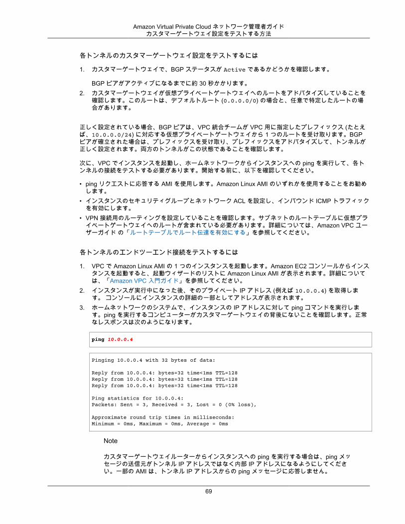
Amazon Virtual Private Cloud ネットワーク管理者ガイドカスタマーゲートウェイ設定をテストする方法
各トンネルのカスタマーゲートウェイ設定をテストするには
1. カスタマーゲートウェイで、BGP ステータスが Active であるかどうかを確認します。
BGP ピアがアクティブになるまでに約 30 秒かかります。2. カスタマーゲートウェイが仮想プライベートゲートウェイへのルートをアドバタイズしていることを
確認します。このルートは、デフォルトルート (0.0.0.0/0) の場合と、任意で特定したルートの場合があります。
正しく設定されている場合、BGP ピアは、VPC 統合チームが VPC 用に指定したプレフィックス (たとえば、10.0.0.0/24) に対応する仮想プライベートゲートウェイから 1 つのルートを受け取ります。BGPピアが確立された場合は、プレフィックスを受け取り、プレフィックスをアドバタイズして、トンネルが正しく設定されます。両方のトンネルがこの状態であることを確認します。
次に、VPC でインスタンスを起動し、ホームネットワークからインスタンスへの ping を実行して、各トンネルの接続をテストする必要があります。開始する前に、以下を確認してください。
• ping リクエストに応答する AMI を使用します。Amazon Linux AMI のいずれかを使用することをお勧めします。
• インスタンスのセキュリティグループとネットワーク ACL を設定し、インバウンド ICMP トラフィックを有効にします。
• VPN 接続用のルーティングを設定していることを確認します。サブネットのルートテーブルに仮想プライベートゲートウェイへのルートが含まれている必要があります。詳細については、Amazon VPC ユーザーガイド の「ルートテーブルでルート伝達を有効にする」を参照してください。
各トンネルのエンドツーエンド接続をテストするには
1. VPC で Amazon Linux AMI の 1 つのインスタンスを起動します。Amazon EC2 コンソールからインスタンスを起動すると、起動ウィザードのリストに Amazon Linux AMI が表示されます。詳細については、「Amazon VPC 入門ガイド」を参照してください。
2. インスタンスが実行中になった後、そのプライベート IP アドレス (例えば 10.0.0.4) を取得します。 コンソールにインスタンスの詳細の一部としてアドレスが表示されます。
3. ホームネットワークのシステムで、インスタンスの IP アドレスに対して ping コマンドを実行します。ping を実行するコンピューターがカスタマーゲートウェイの背後にないことを確認します。正常なレスポンスは次のようになります。
ping 10.0.0.4
Pinging 10.0.0.4 with 32 bytes of data:
Reply from 10.0.0.4: bytes=32 time<1ms TTL=128Reply from 10.0.0.4: bytes=32 time<1ms TTL=128Reply from 10.0.0.4: bytes=32 time<1ms TTL=128
Ping statistics for 10.0.0.4:Packets: Sent = 3, Received = 3, Lost = 0 (0% loss),
Approximate round trip times in milliseconds:Minimum = 0ms, Maximum = 0ms, Average = 0ms
Note
カスタマーゲートウェイルーターからインスタンスへの ping を実行する場合は、ping メッセージの送信元がトンネル IP アドレスではなく内部 IP アドレスになるようにしてください。一部の AMI は、トンネル IP アドレスからの ping メッセージに応答しません。
69
Amazon Virtual Private Cloud ネットワーク管理者ガイドカスタマーゲートウェイ設定をテストする方法
4. (オプション) トンネル フェイルオーバーをテストするため、カスタマーゲートウェイのトンネルの 1つを一時的に無効化し、上記の手順を繰り返すことができます。VPN 接続の AWS 側のトンネルを無効化することはできません。
トンネルのテストを正常に実施できない場合は、「Cisco IOS カスタマーゲートウェイの接続のトラブルシューティング (p. 179)」を参照してください。
70
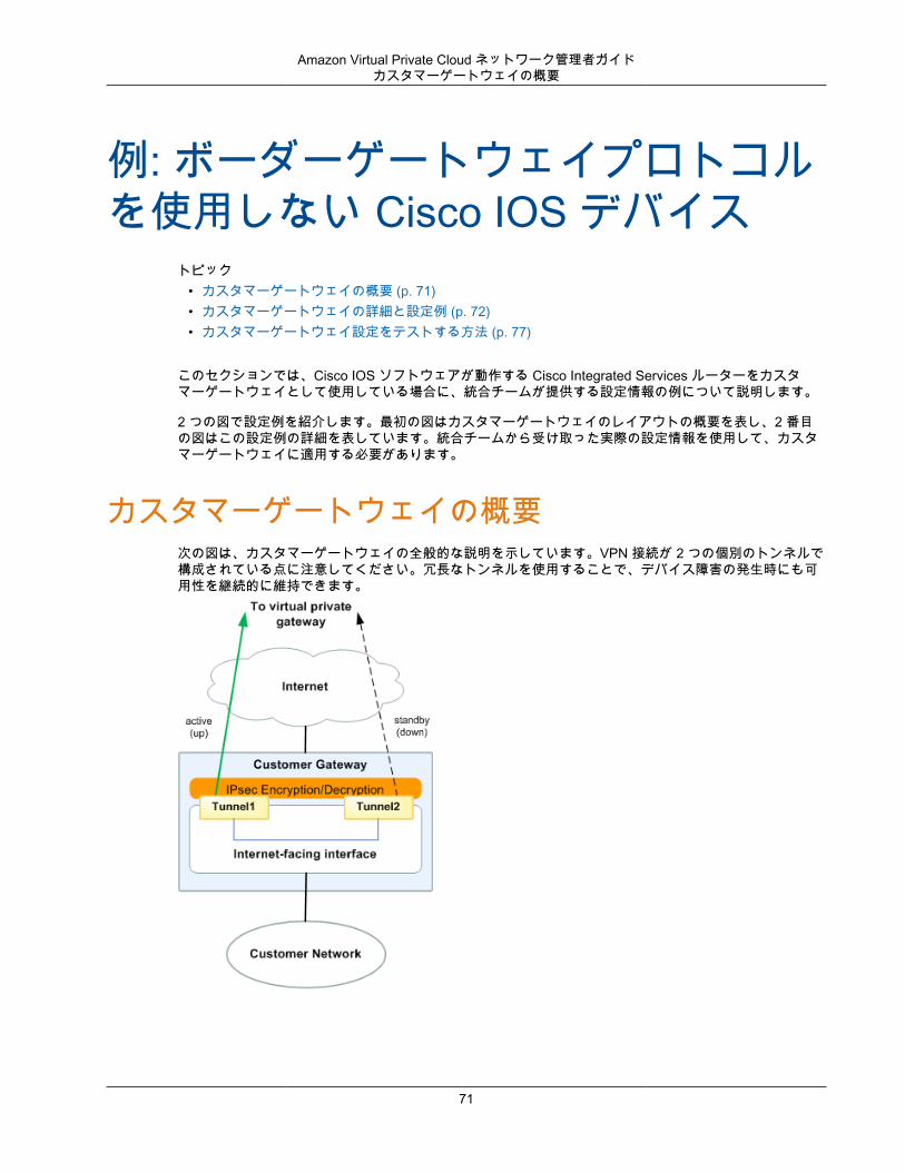
Amazon Virtual Private Cloud ネットワーク管理者ガイドカスタマーゲートウェイの概要
例: ボーダーゲートウェイプロトコルを使用しない Cisco IOS デバイス
トピック• カスタマーゲートウェイの概要 (p. 71)• カスタマーゲートウェイの詳細と設定例 (p. 72)• カスタマーゲートウェイ設定をテストする方法 (p. 77)
このセクションでは、Cisco IOS ソフトウェアが動作する Cisco Integrated Services ルーターをカスタマーゲートウェイとして使用している場合に、統合チームが提供する設定情報の例について説明します。
2 つの図で設定例を紹介します。最初の図はカスタマーゲートウェイのレイアウトの概要を表し、2 番目の図はこの設定例の詳細を表しています。統合チームから受け取った実際の設定情報を使用して、カスタマーゲートウェイに適用する必要があります。
カスタマーゲートウェイの概要次の図は、カスタマーゲートウェイの全般的な説明を示しています。VPN 接続が 2 つの個別のトンネルで構成されている点に注意してください。冗長なトンネルを使用することで、デバイス障害の発生時にも可用性を継続的に維持できます。
71
Amazon Virtual Private Cloud ネットワーク管理者ガイドカスタマーゲートウェイの詳細と設定例
カスタマーゲートウェイの詳細と設定例このセクションの図は、Cisco IOS のカスタマーゲートウェイ (BGP なし) の例を示しています。図の後には、統合チームから提供される設定情報の対応する例が示されています。この設定例には、各トンネルに設定する必要のある一連の情報が含まれています。
さらに、指定する必要がある以下の項目についても示されています。
• YOUR_UPLINK_ADDRESS—カスタマーゲートウェイ上のインターネットルーティングが可能な外部インターフェイスの IP アドレス。このアドレスは静的である必要があります。また、ネットワークアドレス変換 (NAT) を実行するデバイスの背後のアドレスを使用することができます。NAT トラバーサル (NAT-T) を正しく機能させるには、UDP ポート 4500 のブロックを解除するようにファイアウォールのルールを調整する必要があります。
この設定例には、設定がどのように機能するかを理解するために役立つサンプル値が含まれています。たとえば、VPN 接続 ID (vpn-1a4)、仮想プライベートゲートウェイ ID (vpn-1a2b3c4d)、VGW IP アドレス(205.251.233.*, 169.254.255.*) です。これらのサンプル値を、受け取った設定情報に含まれる実際の値で置き換えます。
さらに、以下を実行する必要があります。
• 外部インターフェイスを設定します。• トンネルインターフェイス ID を設定します (設定例では Tunnel1 および Tunnel2 と示されていま
す)。• Crypto ISAKMP Policy Sequence の数値が一意であることを確認します。• Crypto IPsec Transform Set および Crypto ISAKMP Policy Sequence と、デバイスに設定された他のす
べての IPsec トンネルの整合性が確保されていることを確認します。• SLA モニタリング番号が一意であることを確認します。• カスタマーゲートウェイとローカルネットワークとの間でトラフィックを動かす内部ルーティングをす
べて設定します。
次の図および設定例では、イタリックの赤い文字の項目を、特定の設定に適用される値で置き換える必要があります。
72
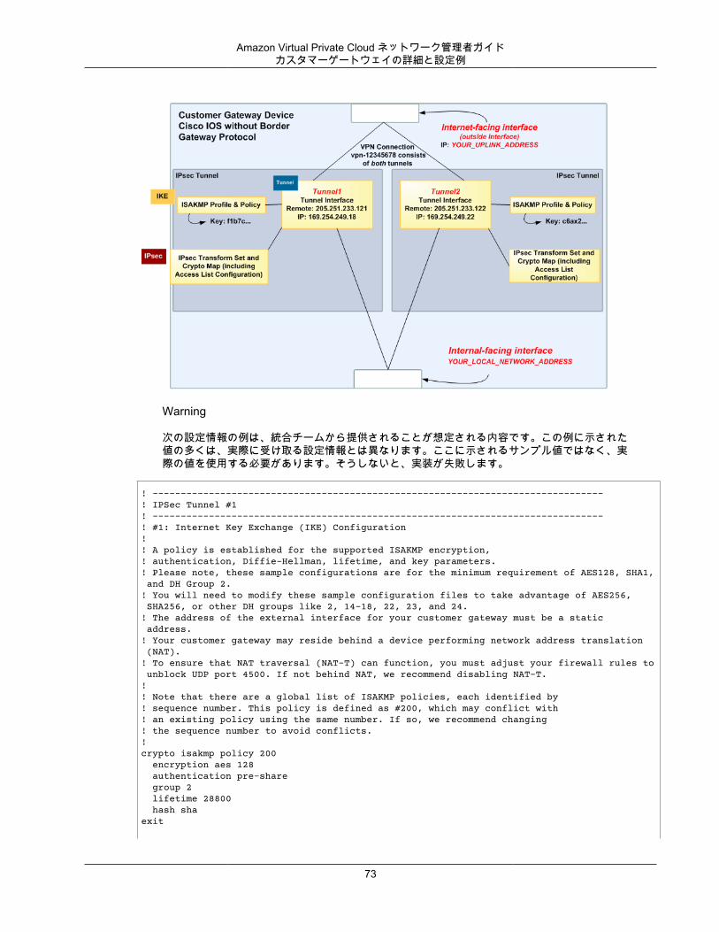
Amazon Virtual Private Cloud ネットワーク管理者ガイドカスタマーゲートウェイの詳細と設定例
Warning
次の設定情報の例は、統合チームから提供されることが想定される内容です。この例に示された値の多くは、実際に受け取る設定情報とは異なります。ここに示されるサンプル値ではなく、実際の値を使用する必要があります。そうしないと、実装が失敗します。
! --------------------------------------------------------------------------------! IPSec Tunnel #1! --------------------------------------------------------------------------------! #1: Internet Key Exchange (IKE) Configuration!! A policy is established for the supported ISAKMP encryption, ! authentication, Diffie-Hellman, lifetime, and key parameters.! Please note, these sample configurations are for the minimum requirement of AES128, SHA1, and DH Group 2.! You will need to modify these sample configuration files to take advantage of AES256, SHA256, or other DH groups like 2, 14-18, 22, 23, and 24.! The address of the external interface for your customer gateway must be a static address. ! Your customer gateway may reside behind a device performing network address translation (NAT).! To ensure that NAT traversal (NAT-T) can function, you must adjust your firewall rules to unblock UDP port 4500. If not behind NAT, we recommend disabling NAT-T.!! Note that there are a global list of ISAKMP policies, each identified by ! sequence number. This policy is defined as #200, which may conflict with! an existing policy using the same number. If so, we recommend changing ! the sequence number to avoid conflicts.!crypto isakmp policy 200 encryption aes 128 authentication pre-share group 2 lifetime 28800 hash shaexit
73
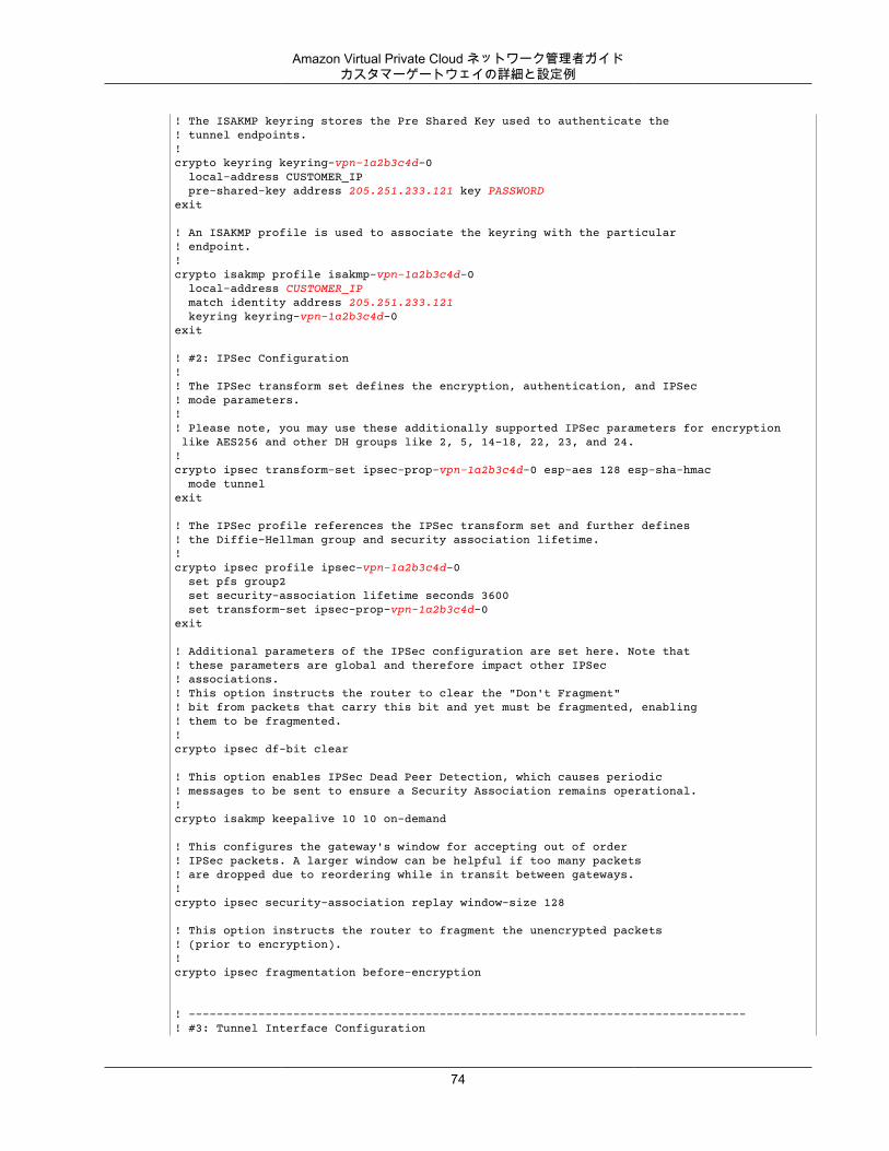
Amazon Virtual Private Cloud ネットワーク管理者ガイドカスタマーゲートウェイの詳細と設定例
! The ISAKMP keyring stores the Pre Shared Key used to authenticate the ! tunnel endpoints.!crypto keyring keyring-vpn-1a2b3c4d-0 local-address CUSTOMER_IP pre-shared-key address 205.251.233.121 key PASSWORDexit
! An ISAKMP profile is used to associate the keyring with the particular ! endpoint.!crypto isakmp profile isakmp-vpn-1a2b3c4d-0 local-address CUSTOMER_IP match identity address 205.251.233.121 keyring keyring-vpn-1a2b3c4d-0exit
! #2: IPSec Configuration! ! The IPSec transform set defines the encryption, authentication, and IPSec! mode parameters.!! Please note, you may use these additionally supported IPSec parameters for encryption like AES256 and other DH groups like 2, 5, 14-18, 22, 23, and 24.!crypto ipsec transform-set ipsec-prop-vpn-1a2b3c4d-0 esp-aes 128 esp-sha-hmac mode tunnelexit
! The IPSec profile references the IPSec transform set and further defines! the Diffie-Hellman group and security association lifetime.!crypto ipsec profile ipsec-vpn-1a2b3c4d-0 set pfs group2 set security-association lifetime seconds 3600 set transform-set ipsec-prop-vpn-1a2b3c4d-0exit
! Additional parameters of the IPSec configuration are set here. Note that ! these parameters are global and therefore impact other IPSec ! associations.! This option instructs the router to clear the "Don't Fragment" ! bit from packets that carry this bit and yet must be fragmented, enabling! them to be fragmented.!crypto ipsec df-bit clear
! This option enables IPSec Dead Peer Detection, which causes periodic! messages to be sent to ensure a Security Association remains operational.!crypto isakmp keepalive 10 10 on-demand
! This configures the gateway's window for accepting out of order! IPSec packets. A larger window can be helpful if too many packets ! are dropped due to reordering while in transit between gateways.!crypto ipsec security-association replay window-size 128
! This option instructs the router to fragment the unencrypted packets! (prior to encryption).!crypto ipsec fragmentation before-encryption
! --------------------------------------------------------------------------------! #3: Tunnel Interface Configuration
74
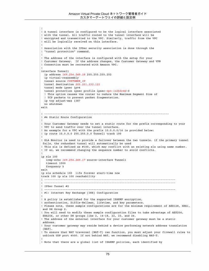
Amazon Virtual Private Cloud ネットワーク管理者ガイドカスタマーゲートウェイの詳細と設定例
! ! A tunnel interface is configured to be the logical interface associated ! with the tunnel. All traffic routed to the tunnel interface will be ! encrypted and transmitted to the VPC. Similarly, traffic from the VPC! will be logically received on this interface.!! Association with the IPSec security association is done through the ! "tunnel protection" command.!! The address of the interface is configured with the setup for your ! Customer Gateway. If the address changes, the Customer Gateway and VPN ! Connection must be recreated with Amazon VPC.!interface Tunnel1 ip address 169.254.249.18 255.255.255.252 ip virtual-reassembly tunnel source CUSTOMER_IP tunnel destination 205.251.233.121 tunnel mode ipsec ipv4 tunnel protection ipsec profile ipsec-vpn-1a2b3c4d-0 ! This option causes the router to reduce the Maximum Segment Size of ! TCP packets to prevent packet fragmentation. ip tcp adjust-mss 1387 no shutdownexit
! ----------------------------------------------------------------------------! #4 Static Route Configuration!! Your Customer Gateway needs to set a static route for the prefix corresponding to your ! VPC to send traffic over the tunnel interface.! An example for a VPC with the prefix 10.0.0.0/16 is provided below:! ip route 10.0.0.0 255.255.0.0 Tunnel1 track 100 !! SLA Monitor is used to provide a failover between the two tunnels. If the primary tunnel fails, the redundant tunnel will automatically be used! This sla is defined as #100, which may conflict with an existing sla using same number. ! If so, we recommend changing the sequence number to avoid conflicts.!ip sla 100 icmp-echo 169.254.249.17 source-interface Tunnel1 timeout 1000 frequency 5exitip sla schedule 100 life forever start-time nowtrack 100 ip sla 100 reachability ! --------------------------------------------------------------------------------! --------------------------------------------------------------------------------! IPSec Tunnel #2! --------------------------------------------------------------------------------! #1: Internet Key Exchange (IKE) Configuration!! A policy is established for the supported ISAKMP encryption, ! authentication, Diffie-Hellman, lifetime, and key parameters.! Please note, these sample configurations are for the minimum requirement of AES128, SHA1, and DH Group 2.! You will need to modify these sample configuration files to take advantage of AES256, SHA256, or other DH groups like 2, 14-18, 22, 23, and 24.! The address of the external interface for your customer gateway must be a static address. ! Your customer gateway may reside behind a device performing network address translation (NAT).! To ensure that NAT traversal (NAT-T) can function, you must adjust your firewall rules to unblock UDP port 4500. If not behind NAT, we recommend disabling NAT-T.!! Note that there are a global list of ISAKMP policies, each identified by
75
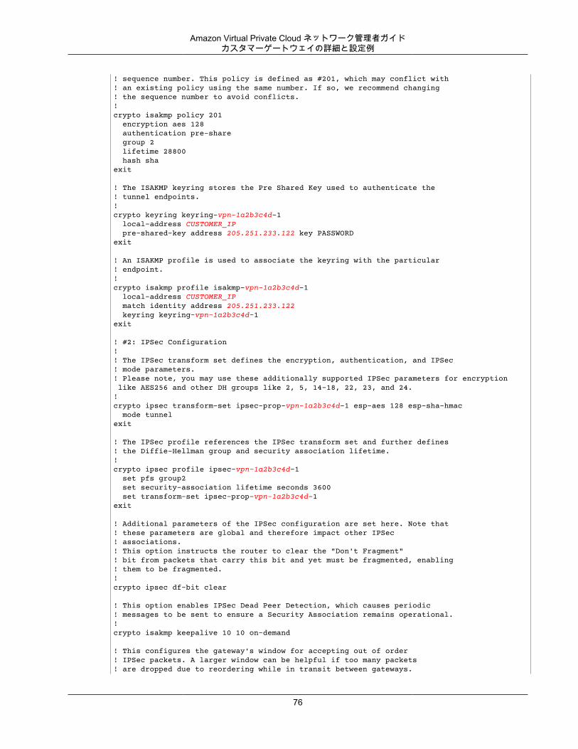
Amazon Virtual Private Cloud ネットワーク管理者ガイドカスタマーゲートウェイの詳細と設定例
! sequence number. This policy is defined as #201, which may conflict with! an existing policy using the same number. If so, we recommend changing ! the sequence number to avoid conflicts.!crypto isakmp policy 201 encryption aes 128 authentication pre-share group 2 lifetime 28800 hash shaexit
! The ISAKMP keyring stores the Pre Shared Key used to authenticate the ! tunnel endpoints.!crypto keyring keyring-vpn-1a2b3c4d-1 local-address CUSTOMER_IP pre-shared-key address 205.251.233.122 key PASSWORDexit
! An ISAKMP profile is used to associate the keyring with the particular ! endpoint.!crypto isakmp profile isakmp-vpn-1a2b3c4d-1 local-address CUSTOMER_IP match identity address 205.251.233.122 keyring keyring-vpn-1a2b3c4d-1exit
! #2: IPSec Configuration! ! The IPSec transform set defines the encryption, authentication, and IPSec! mode parameters.! Please note, you may use these additionally supported IPSec parameters for encryption like AES256 and other DH groups like 2, 5, 14-18, 22, 23, and 24.!crypto ipsec transform-set ipsec-prop-vpn-1a2b3c4d-1 esp-aes 128 esp-sha-hmac mode tunnelexit
! The IPSec profile references the IPSec transform set and further defines! the Diffie-Hellman group and security association lifetime.!crypto ipsec profile ipsec-vpn-1a2b3c4d-1 set pfs group2 set security-association lifetime seconds 3600 set transform-set ipsec-prop-vpn-1a2b3c4d-1exit
! Additional parameters of the IPSec configuration are set here. Note that ! these parameters are global and therefore impact other IPSec ! associations.! This option instructs the router to clear the "Don't Fragment" ! bit from packets that carry this bit and yet must be fragmented, enabling! them to be fragmented.!crypto ipsec df-bit clear
! This option enables IPSec Dead Peer Detection, which causes periodic! messages to be sent to ensure a Security Association remains operational.!crypto isakmp keepalive 10 10 on-demand
! This configures the gateway's window for accepting out of order! IPSec packets. A larger window can be helpful if too many packets ! are dropped due to reordering while in transit between gateways.
76
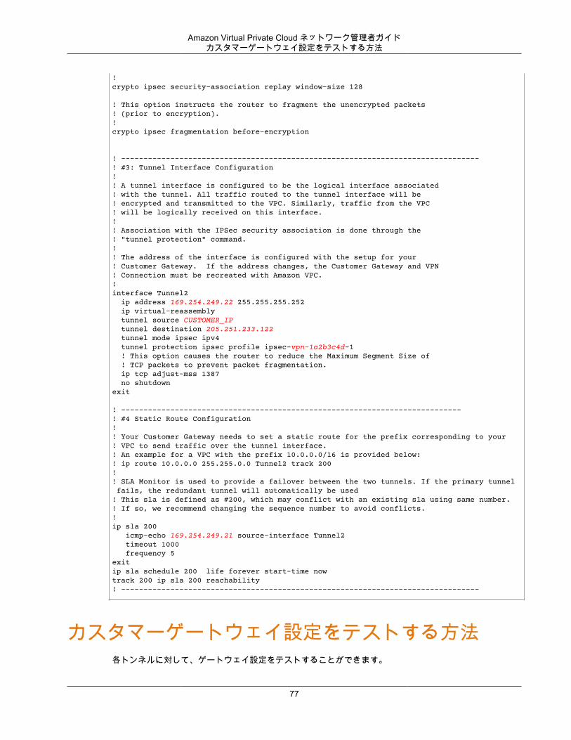
Amazon Virtual Private Cloud ネットワーク管理者ガイドカスタマーゲートウェイ設定をテストする方法
!crypto ipsec security-association replay window-size 128
! This option instructs the router to fragment the unencrypted packets! (prior to encryption).!crypto ipsec fragmentation before-encryption
! --------------------------------------------------------------------------------! #3: Tunnel Interface Configuration! ! A tunnel interface is configured to be the logical interface associated ! with the tunnel. All traffic routed to the tunnel interface will be ! encrypted and transmitted to the VPC. Similarly, traffic from the VPC! will be logically received on this interface.!! Association with the IPSec security association is done through the ! "tunnel protection" command.!! The address of the interface is configured with the setup for your ! Customer Gateway. If the address changes, the Customer Gateway and VPN ! Connection must be recreated with Amazon VPC.!interface Tunnel2 ip address 169.254.249.22 255.255.255.252 ip virtual-reassembly tunnel source CUSTOMER_IP tunnel destination 205.251.233.122 tunnel mode ipsec ipv4 tunnel protection ipsec profile ipsec-vpn-1a2b3c4d-1 ! This option causes the router to reduce the Maximum Segment Size of ! TCP packets to prevent packet fragmentation. ip tcp adjust-mss 1387 no shutdownexit
! ----------------------------------------------------------------------------! #4 Static Route Configuration!! Your Customer Gateway needs to set a static route for the prefix corresponding to your ! VPC to send traffic over the tunnel interface.! An example for a VPC with the prefix 10.0.0.0/16 is provided below:! ip route 10.0.0.0 255.255.0.0 Tunnel2 track 200 !! SLA Monitor is used to provide a failover between the two tunnels. If the primary tunnel fails, the redundant tunnel will automatically be used! This sla is defined as #200, which may conflict with an existing sla using same number. ! If so, we recommend changing the sequence number to avoid conflicts.!ip sla 200 icmp-echo 169.254.249.21 source-interface Tunnel2 timeout 1000 frequency 5exitip sla schedule 200 life forever start-time nowtrack 200 ip sla 200 reachability ! --------------------------------------------------------------------------------
カスタマーゲートウェイ設定をテストする方法各トンネルに対して、ゲートウェイ設定をテストすることができます。
77
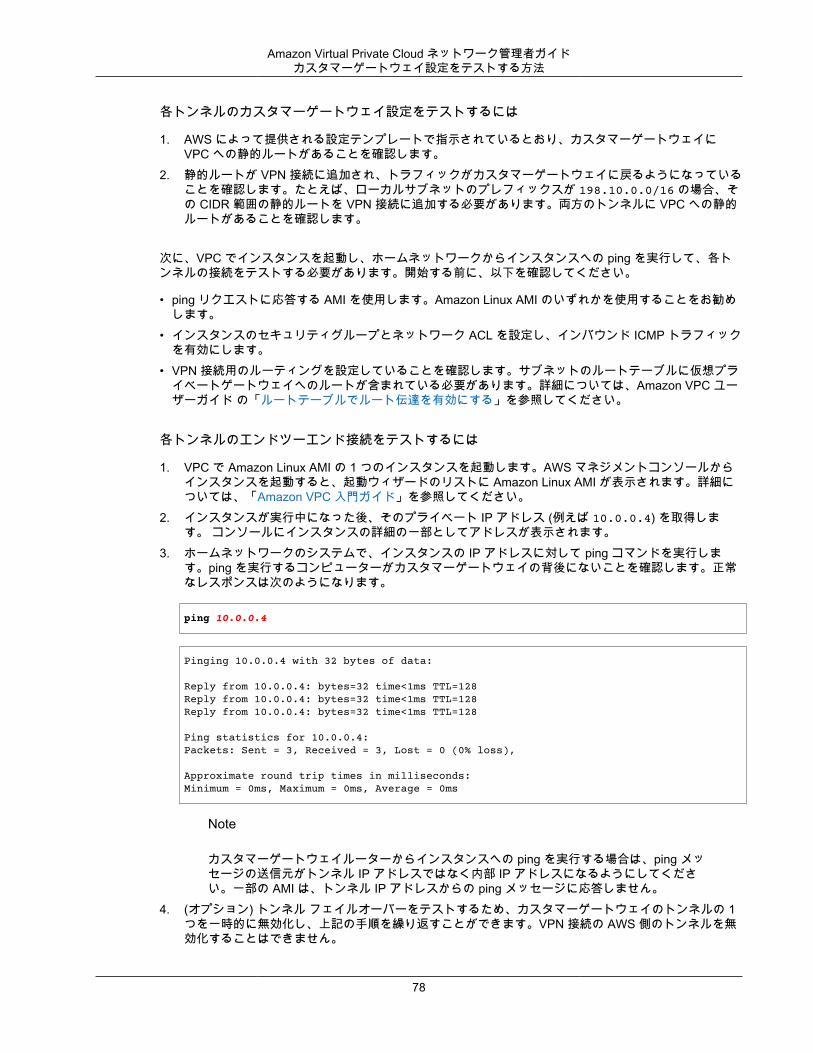
Amazon Virtual Private Cloud ネットワーク管理者ガイドカスタマーゲートウェイ設定をテストする方法
各トンネルのカスタマーゲートウェイ設定をテストするには
1. AWS によって提供される設定テンプレートで指示されているとおり、カスタマーゲートウェイにVPC への静的ルートがあることを確認します。
2. 静的ルートが VPN 接続に追加され、トラフィックがカスタマーゲートウェイに戻るようになっていることを確認します。たとえば、ローカルサブネットのプレフィックスが 198.10.0.0/16 の場合、その CIDR 範囲の静的ルートを VPN 接続に追加する必要があります。両方のトンネルに VPC への静的ルートがあることを確認します。
次に、VPC でインスタンスを起動し、ホームネットワークからインスタンスへの ping を実行して、各トンネルの接続をテストする必要があります。開始する前に、以下を確認してください。
• ping リクエストに応答する AMI を使用します。Amazon Linux AMI のいずれかを使用することをお勧めします。
• インスタンスのセキュリティグループとネットワーク ACL を設定し、インバウンド ICMP トラフィックを有効にします。
• VPN 接続用のルーティングを設定していることを確認します。サブネットのルートテーブルに仮想プライベートゲートウェイへのルートが含まれている必要があります。詳細については、Amazon VPC ユーザーガイド の「ルートテーブルでルート伝達を有効にする」を参照してください。
各トンネルのエンドツーエンド接続をテストするには
1. VPC で Amazon Linux AMI の 1 つのインスタンスを起動します。AWS マネジメントコンソールからインスタンスを起動すると、起動ウィザードのリストに Amazon Linux AMI が表示されます。詳細については、「Amazon VPC 入門ガイド」を参照してください。
2. インスタンスが実行中になった後、そのプライベート IP アドレス (例えば 10.0.0.4) を取得します。 コンソールにインスタンスの詳細の一部としてアドレスが表示されます。
3. ホームネットワークのシステムで、インスタンスの IP アドレスに対して ping コマンドを実行します。ping を実行するコンピューターがカスタマーゲートウェイの背後にないことを確認します。正常なレスポンスは次のようになります。
ping 10.0.0.4
Pinging 10.0.0.4 with 32 bytes of data:
Reply from 10.0.0.4: bytes=32 time<1ms TTL=128Reply from 10.0.0.4: bytes=32 time<1ms TTL=128Reply from 10.0.0.4: bytes=32 time<1ms TTL=128
Ping statistics for 10.0.0.4:Packets: Sent = 3, Received = 3, Lost = 0 (0% loss),
Approximate round trip times in milliseconds:Minimum = 0ms, Maximum = 0ms, Average = 0ms
Note
カスタマーゲートウェイルーターからインスタンスへの ping を実行する場合は、ping メッセージの送信元がトンネル IP アドレスではなく内部 IP アドレスになるようにしてください。一部の AMI は、トンネル IP アドレスからの ping メッセージに応答しません。
4. (オプション) トンネル フェイルオーバーをテストするため、カスタマーゲートウェイのトンネルの 1つを一時的に無効化し、上記の手順を繰り返すことができます。VPN 接続の AWS 側のトンネルを無効化することはできません。
78

Amazon Virtual Private Cloud ネットワーク管理者ガイドカスタマーゲートウェイ設定をテストする方法
トンネルのテストを正常に実施できない場合は、「ボーダーゲートウェイプロトコル接続を使用しないCisco IOS カスタマーゲートウェイのトラブルシューティング (p. 184)」を参照してください。
79
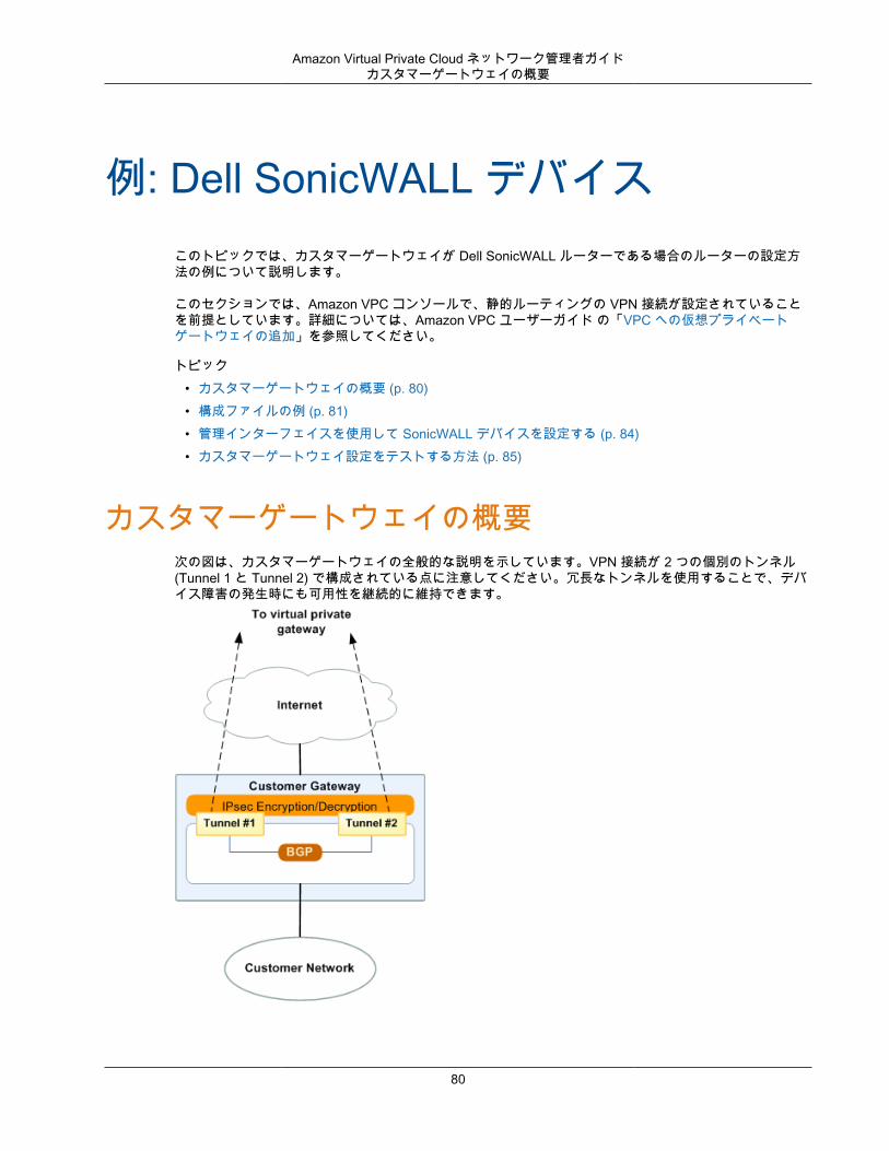
Amazon Virtual Private Cloud ネットワーク管理者ガイドカスタマーゲートウェイの概要
例: Dell SonicWALL デバイスこのトピックでは、カスタマーゲートウェイが Dell SonicWALL ルーターである場合のルーターの設定方法の例について説明します。
このセクションでは、Amazon VPC コンソールで、静的ルーティングの VPN 接続が設定されていることを前提としています。詳細については、Amazon VPC ユーザーガイド の「VPC への仮想プライベートゲートウェイの追加」を参照してください。
トピック• カスタマーゲートウェイの概要 (p. 80)• 構成ファイルの例 (p. 81)• 管理インターフェイスを使用して SonicWALL デバイスを設定する (p. 84)• カスタマーゲートウェイ設定をテストする方法 (p. 85)
カスタマーゲートウェイの概要次の図は、カスタマーゲートウェイの全般的な説明を示しています。VPN 接続が 2 つの個別のトンネル(Tunnel 1 と Tunnel 2) で構成されている点に注意してください。冗長なトンネルを使用することで、デバイス障害の発生時にも可用性を継続的に維持できます。
80
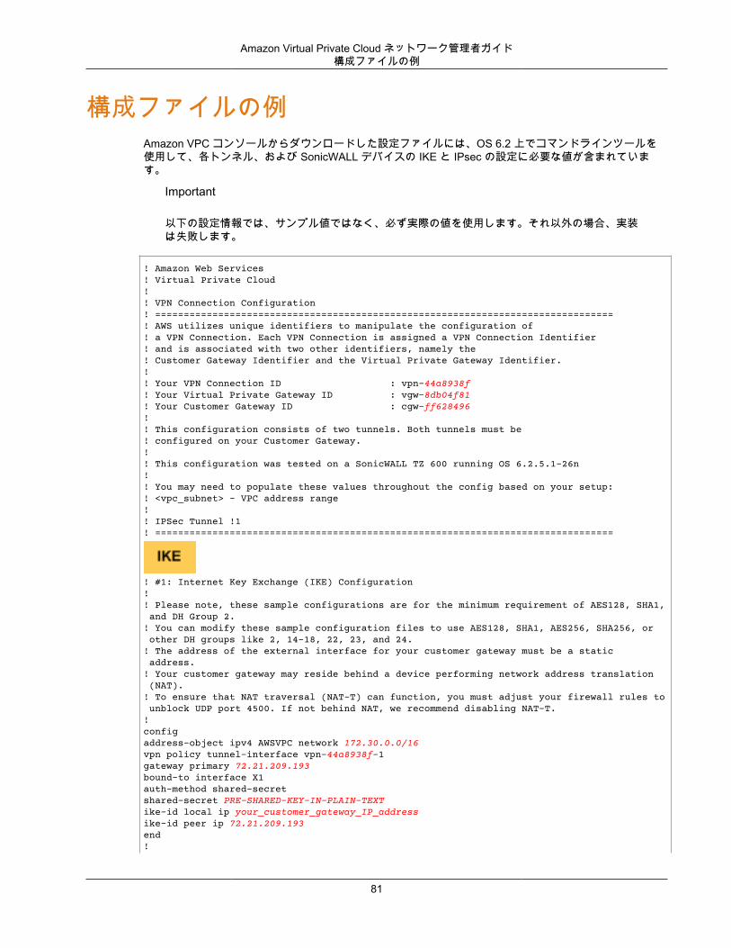
Amazon Virtual Private Cloud ネットワーク管理者ガイド構成ファイルの例
構成ファイルの例Amazon VPC コンソールからダウンロードした設定ファイルには、OS 6.2 上でコマンドラインツールを使用して、各トンネル、および SonicWALL デバイスの IKE と IPsec の設定に必要な値が含まれています。
Important
以下の設定情報では、サンプル値ではなく、必ず実際の値を使用します。それ以外の場合、実装は失敗します。
! Amazon Web Services! Virtual Private Cloud!! VPN Connection Configuration! ================================================================================! AWS utilizes unique identifiers to manipulate the configuration of! a VPN Connection. Each VPN Connection is assigned a VPN Connection Identifier! and is associated with two other identifiers, namely the! Customer Gateway Identifier and the Virtual Private Gateway Identifier.!! Your VPN Connection ID : vpn-44a8938f! Your Virtual Private Gateway ID : vgw-8db04f81! Your Customer Gateway ID : cgw-ff628496!! This configuration consists of two tunnels. Both tunnels must be ! configured on your Customer Gateway.!! This configuration was tested on a SonicWALL TZ 600 running OS 6.2.5.1-26n!! You may need to populate these values throughout the config based on your setup:! <vpc_subnet> - VPC address range!! IPSec Tunnel !1! ================================================================================
! #1: Internet Key Exchange (IKE) Configuration! ! Please note, these sample configurations are for the minimum requirement of AES128, SHA1, and DH Group 2.! You can modify these sample configuration files to use AES128, SHA1, AES256, SHA256, or other DH groups like 2, 14-18, 22, 23, and 24.! The address of the external interface for your customer gateway must be a static address. ! Your customer gateway may reside behind a device performing network address translation (NAT).! To ensure that NAT traversal (NAT-T) can function, you must adjust your firewall rules to unblock UDP port 4500. If not behind NAT, we recommend disabling NAT-T.!configaddress-object ipv4 AWSVPC network 172.30.0.0/16vpn policy tunnel-interface vpn-44a8938f-1gateway primary 72.21.209.193bound-to interface X1auth-method shared-secret shared-secret PRE-SHARED-KEY-IN-PLAIN-TEXTike-id local ip your_customer_gateway_IP_address ike-id peer ip 72.21.209.193end!
81
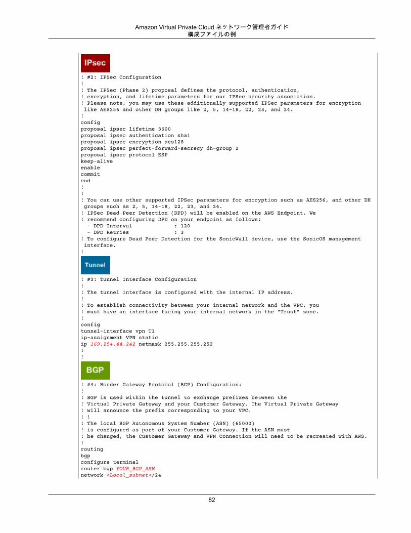
Amazon Virtual Private Cloud ネットワーク管理者ガイド構成ファイルの例
! #2: IPSec Configuration! ! The IPSec (Phase 2) proposal defines the protocol, authentication, ! encryption, and lifetime parameters for our IPSec security association.! Please note, you may use these additionally supported IPSec parameters for encryption like AES256 and other DH groups like 2, 5, 14-18, 22, 23, and 24.!configproposal ipsec lifetime 3600proposal ipsec authentication sha1proposal ipsec encryption aes128proposal ipsec perfect-forward-secrecy dh-group 2proposal ipsec protocol ESPkeep-alive enablecommit end !!! You can use other supported IPSec parameters for encryption such as AES256, and other DH groups such as 2, 5, 14-18, 22, 23, and 24.! IPSec Dead Peer Detection (DPD) will be enabled on the AWS Endpoint. We! recommend configuring DPD on your endpoint as follows: - DPD Interval : 120 - DPD Retries : 3! To configure Dead Peer Detection for the SonicWall device, use the SonicOS management interface.!
! #3: Tunnel Interface Configuration! ! The tunnel interface is configured with the internal IP address.!! To establish connectivity between your internal network and the VPC, you! must have an interface facing your internal network in the "Trust" zone.!configtunnel-interface vpn T1ip-assignment VPN staticip 169.254.44.242 netmask 255.255.255.252!!
! #4: Border Gateway Protocol (BGP) Configuration:! ! BGP is used within the tunnel to exchange prefixes between the! Virtual Private Gateway and your Customer Gateway. The Virtual Private Gateway ! will announce the prefix corresponding to your VPC.! !! The local BGP Autonomous System Number (ASN) (65000)! is configured as part of your Customer Gateway. If the ASN must ! be changed, the Customer Gateway and VPN Connection will need to be recreated with AWS.!routingbgpconfigure terminal router bgp YOUR_BGP_ASNnetwork <Local_subnet>/24
82
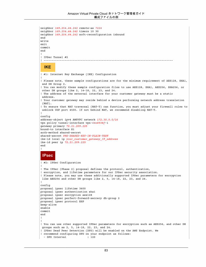
Amazon Virtual Private Cloud ネットワーク管理者ガイド構成ファイルの例
neighbor 169.254.44.242 remote-as 7224neighbor 169.254.44.242 timers 10 30neighbor 169.254.44.242 soft-reconfiguration inboundendwriteexitcommitend!! IPSec Tunnel #2! --------------------------------------------------------------------------------
! #1: Internet Key Exchange (IKE) Configuration! ! Please note, these sample configurations are for the minimum requirement of AES128, SHA1, and DH Group 2.! You can modify these sample configuration files to use AES128, SHA1, AES256, SHA256, or other DH groups like 2, 14-18, 22, 23, and 24.! The address of the external interface for your customer gateway must be a static address. ! Your customer gateway may reside behind a device performing network address translation (NAT).! To ensure that NAT traversal (NAT-T) can function, you must adjust your firewall rules to unblock UDP port 4500. If not behind NAT, we recommend disabling NAT-T.!configaddress-object ipv4 AWSVPC network 172.30.0.0/16vpn policy tunnel-interface vpn-44a8938f-1gateway primary 72.21.209.225bound-to interface X1auth-method shared-secret shared-secret PRE-SHARED-KEY-IN-PLAIN-TEXTike-id local ip your_customer_gateway_IP_address ike-id peer ip 72.21.209.225 end!
! #2: IPSec Configuration! ! The IPSec (Phase 2) proposal defines the protocol, authentication, ! encryption, and lifetime parameters for our IPSec security association.! Please note, you may use these additionally supported IPSec parameters for encryption like AES256 and other DH groups like 2, 5, 14-18, 22, 23, and 24.!configproposal ipsec lifetime 3600proposal ipsec authentication sha1proposal ipsec encryption aes128proposal ipsec perfect-forward-secrecy dh-group 2proposal ipsec protocol ESPkeep-alive enablecommit end !!! You can use other supported IPSec parameters for encryption such as AES256, and other DH groups such as 2, 5, 14-18, 22, 23, and 24.! IPSec Dead Peer Detection (DPD) will be enabled on the AWS Endpoint. We! recommend configuring DPD on your endpoint as follows: - DPD Interval : 120
83
Amazon Virtual Private Cloud ネットワーク管理者ガイド管理インターフェイスを使用し
て SonicWALL デバイスを設定する
- DPD Retries : 3! To configure Dead Peer Detection for the SonicWall device, use the SonicOS management interface.!
! #3: Tunnel Interface Configuration! ! The tunnel interface is configured with the internal IP address.!! To establish connectivity between your internal network and the VPC, you! must have an interface facing your internal network in the "Trust" zone.!configtunnel-interface vpn T2ip-assignment VPN staticip 169.254.44.114 netmask 255.255.255.252!
! #4: Border Gateway Protocol (BGP) Configuration:! ! BGP is used within the tunnel to exchange prefixes between the! Virtual Private Gateway and your Customer Gateway. The Virtual Private Gateway ! will announce the prefix corresponding to your VPC.!! The local BGP Autonomous System Number (ASN) (65000)! is configured as part of your Customer Gateway. If the ASN must ! be changed, the Customer Gateway and VPN Connection will need to be recreated with AWS.!routingbgpconfigure terminal router bgp YOUR_BGP_ASNnetwork <Local_subnet>/24neighbor 169.254.44.114 remote-as 7224neighbor 169.254.44.114 timers 10 30neighbor 169.254.44.114 soft-reconfiguration inboundendwriteexitcommitend
管理インターフェイスを使用して SonicWALL デバイスを設定する
また、SonicOS 管理インターフェイスを使用して SonicWALL デバイスを設定することもできます。詳細については、「管理インターフェイスを使用して SonicWALL デバイスを設定する (p. 91)」を参照してください。
このSonicOS 管理インターフェイスを使用して、デバイスの BGP を設定することはできません。代わりに、[BGP] というセクションの下にある、上記例の設定ファイル内のコマンドライン手順を使用します。
84
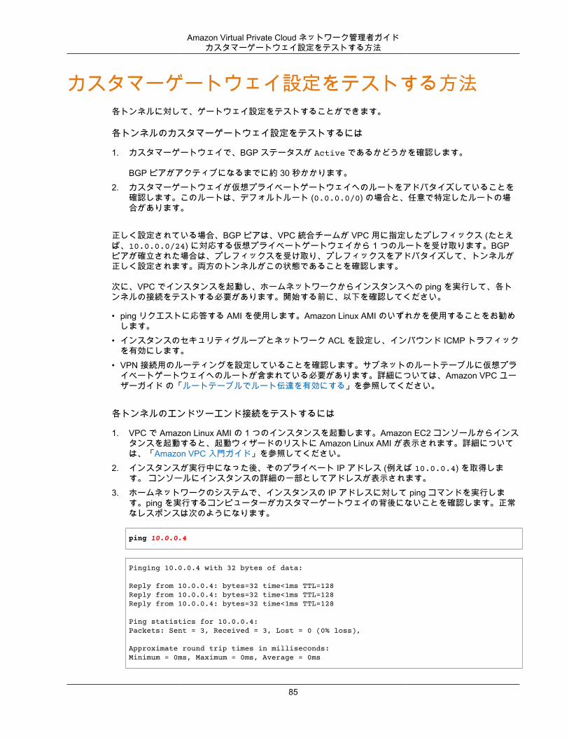
Amazon Virtual Private Cloud ネットワーク管理者ガイドカスタマーゲートウェイ設定をテストする方法
カスタマーゲートウェイ設定をテストする方法各トンネルに対して、ゲートウェイ設定をテストすることができます。
各トンネルのカスタマーゲートウェイ設定をテストするには
1. カスタマーゲートウェイで、BGP ステータスが Active であるかどうかを確認します。
BGP ピアがアクティブになるまでに約 30 秒かかります。2. カスタマーゲートウェイが仮想プライベートゲートウェイへのルートをアドバタイズしていることを
確認します。このルートは、デフォルトルート (0.0.0.0/0) の場合と、任意で特定したルートの場合があります。
正しく設定されている場合、BGP ピアは、VPC 統合チームが VPC 用に指定したプレフィックス (たとえば、10.0.0.0/24) に対応する仮想プライベートゲートウェイから 1 つのルートを受け取ります。BGPピアが確立された場合は、プレフィックスを受け取り、プレフィックスをアドバタイズして、トンネルが正しく設定されます。両方のトンネルがこの状態であることを確認します。
次に、VPC でインスタンスを起動し、ホームネットワークからインスタンスへの ping を実行して、各トンネルの接続をテストする必要があります。開始する前に、以下を確認してください。
• ping リクエストに応答する AMI を使用します。Amazon Linux AMI のいずれかを使用することをお勧めします。
• インスタンスのセキュリティグループとネットワーク ACL を設定し、インバウンド ICMP トラフィックを有効にします。
• VPN 接続用のルーティングを設定していることを確認します。サブネットのルートテーブルに仮想プライベートゲートウェイへのルートが含まれている必要があります。詳細については、Amazon VPC ユーザーガイド の「ルートテーブルでルート伝達を有効にする」を参照してください。
各トンネルのエンドツーエンド接続をテストするには
1. VPC で Amazon Linux AMI の 1 つのインスタンスを起動します。Amazon EC2 コンソールからインスタンスを起動すると、起動ウィザードのリストに Amazon Linux AMI が表示されます。詳細については、「Amazon VPC 入門ガイド」を参照してください。
2. インスタンスが実行中になった後、そのプライベート IP アドレス (例えば 10.0.0.4) を取得します。 コンソールにインスタンスの詳細の一部としてアドレスが表示されます。
3. ホームネットワークのシステムで、インスタンスの IP アドレスに対して ping コマンドを実行します。ping を実行するコンピューターがカスタマーゲートウェイの背後にないことを確認します。正常なレスポンスは次のようになります。
ping 10.0.0.4
Pinging 10.0.0.4 with 32 bytes of data:
Reply from 10.0.0.4: bytes=32 time<1ms TTL=128Reply from 10.0.0.4: bytes=32 time<1ms TTL=128Reply from 10.0.0.4: bytes=32 time<1ms TTL=128
Ping statistics for 10.0.0.4:Packets: Sent = 3, Received = 3, Lost = 0 (0% loss),
Approximate round trip times in milliseconds:Minimum = 0ms, Maximum = 0ms, Average = 0ms
85
Amazon Virtual Private Cloud ネットワーク管理者ガイドカスタマーゲートウェイ設定をテストする方法
Note
カスタマーゲートウェイルーターからインスタンスへの ping を実行する場合は、ping メッセージの送信元がトンネル IP アドレスではなく内部 IP アドレスになるようにしてください。一部の AMI は、トンネル IP アドレスからの ping メッセージに応答しません。
4. (オプション) トンネル フェイルオーバーをテストするため、カスタマーゲートウェイのトンネルの 1つを一時的に無効化し、上記の手順を繰り返すことができます。VPN 接続の AWS 側のトンネルを無効化することはできません。
トンネルのテストを正常に実施できない場合は、「ボーダーゲートウェイプロトコルを使用した一般的なデバイスのカスタマーゲートウェイ接続のトラブルシューティング (p. 197)」を参照してください。
86
Amazon Virtual Private Cloud ネットワーク管理者ガイドカスタマーゲートウェイの概要
例: ボーダーゲートウェイプロトコルを使用しない Dell SonicWALLSonicOS デバイス
このトピックでは、カスタマーゲートウェイが、SonicOS 5.9 または 6.2 を搭載した Dell SonicWALL ルーターの場合のルーターの設定方法の例を取り上げます。
このセクションでは、Amazon VPC コンソールで、静的ルーティングの VPN 接続が設定されていることを前提としています。詳細については、Amazon VPC ユーザーガイド の「VPC への仮想プライベートゲートウェイの追加」を参照してください。
トピック• カスタマーゲートウェイの概要 (p. 87)• 構成ファイルの例 (p. 88)• 管理インターフェイスを使用して SonicWALL デバイスを設定する (p. 91)• カスタマーゲートウェイ設定をテストする方法 (p. 93)
カスタマーゲートウェイの概要次の図は、カスタマーゲートウェイの全般的な説明を示しています。VPN 接続が 2 つの個別のトンネル(Tunnel 1 と Tunnel 2) で構成されている点に注意してください。冗長なトンネルを使用することで、デバイス障害の発生時にも可用性を継続的に維持できます。
87
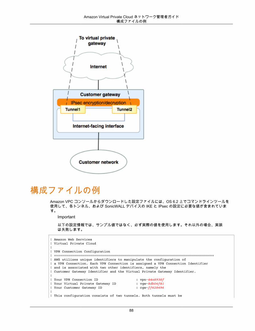
Amazon Virtual Private Cloud ネットワーク管理者ガイド構成ファイルの例
構成ファイルの例Amazon VPC コンソールからダウンロードした設定ファイルには、OS 6.2 上でコマンドラインツールを使用して、各トンネル、および SonicWALL デバイスの IKE と IPsec の設定に必要な値が含まれています。
Important
以下の設定情報では、サンプル値ではなく、必ず実際の値を使用します。それ以外の場合、実装は失敗します。
! Amazon Web Services! Virtual Private Cloud!! VPN Connection Configuration! ================================================================================! AWS utilizes unique identifiers to manipulate the configuration of! a VPN Connection. Each VPN Connection is assigned a VPN Connection Identifier! and is associated with two other identifiers, namely the! Customer Gateway Identifier and the Virtual Private Gateway Identifier.!! Your VPN Connection ID : vpn-44a8938f! Your Virtual Private Gateway ID : vgw-8db04f81! Your Customer Gateway ID : cgw-ff628496! ! This configuration consists of two tunnels. Both tunnels must be
88
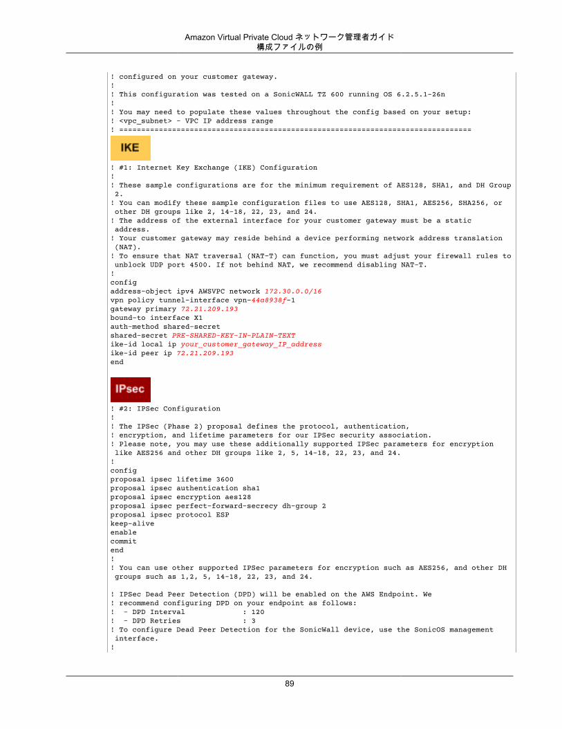
Amazon Virtual Private Cloud ネットワーク管理者ガイド構成ファイルの例
! configured on your customer gateway.!! This configuration was tested on a SonicWALL TZ 600 running OS 6.2.5.1-26n!! You may need to populate these values throughout the config based on your setup:! <vpc_subnet> - VPC IP address range! ================================================================================
! #1: Internet Key Exchange (IKE) Configuration! ! These sample configurations are for the minimum requirement of AES128, SHA1, and DH Group 2.! You can modify these sample configuration files to use AES128, SHA1, AES256, SHA256, or other DH groups like 2, 14-18, 22, 23, and 24.! The address of the external interface for your customer gateway must be a static address. ! Your customer gateway may reside behind a device performing network address translation (NAT).! To ensure that NAT traversal (NAT-T) can function, you must adjust your firewall rules to unblock UDP port 4500. If not behind NAT, we recommend disabling NAT-T.!configaddress-object ipv4 AWSVPC network 172.30.0.0/16vpn policy tunnel-interface vpn-44a8938f-1gateway primary 72.21.209.193bound-to interface X1auth-method shared-secret shared-secret PRE-SHARED-KEY-IN-PLAIN-TEXTike-id local ip your_customer_gateway_IP_address ike-id peer ip 72.21.209.193 end
! #2: IPSec Configuration! ! The IPSec (Phase 2) proposal defines the protocol, authentication, ! encryption, and lifetime parameters for our IPSec security association.! Please note, you may use these additionally supported IPSec parameters for encryption like AES256 and other DH groups like 2, 5, 14-18, 22, 23, and 24.!configproposal ipsec lifetime 3600proposal ipsec authentication sha1proposal ipsec encryption aes128proposal ipsec perfect-forward-secrecy dh-group 2proposal ipsec protocol ESPkeep-alive enablecommit end !! You can use other supported IPSec parameters for encryption such as AES256, and other DH groups such as 1,2, 5, 14-18, 22, 23, and 24.
! IPSec Dead Peer Detection (DPD) will be enabled on the AWS Endpoint. We! recommend configuring DPD on your endpoint as follows:! - DPD Interval : 120! - DPD Retries : 3! To configure Dead Peer Detection for the SonicWall device, use the SonicOS management interface.!
89
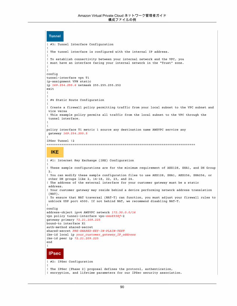
Amazon Virtual Private Cloud ネットワーク管理者ガイド構成ファイルの例
! #3: Tunnel Interface Configuration! ! The tunnel interface is configured with the internal IP address.!! To establish connectivity between your internal network and the VPC, you! must have an interface facing your internal network in the "Trust" zone.!!configtunnel-interface vpn T1ip-assignment VPN staticip 169.254.255.6 netmask 255.255.255.252exit!! ! #4 Static Route Configuration!! Create a firewall policy permitting traffic from your local subnet to the VPC subnet and vice versa! This example policy permits all traffic from the local subnet to the VPC through the tunnel interface.!!policy interface T1 metric 1 source any destination name AWSVPC service any gateway 169.254.255.5! IPSec Tunnel !2 ================================================================================
! #1: Internet Key Exchange (IKE) Configuration! ! These sample configurations are for the minimum requirement of AES128, SHA1, and DH Group 2.! You can modify these sample configuration files to use AES128, SHA1, AES256, SHA256, or other DH groups like 2, 14-18, 22, 23, and 24.! The address of the external interface for your customer gateway must be a static address. ! Your customer gateway may reside behind a device performing network address translation (NAT).! To ensure that NAT traversal (NAT-T) can function, you must adjust your firewall rules to unblock UDP port 4500. If not behind NAT, we recommend disabling NAT-T.!configaddress-object ipv4 AWSVPC network 172.30.0.0/16vpn policy tunnel-interface vpn-44a8938f-2gateway primary 72.21.209.225bound-to interface X1auth-method shared-secret shared-secret PRE-SHARED-KEY-IN-PLAIN-TEXTike-id local ip your_customer_gateway_IP_address ike-id peer ip 72.21.209.225end!
! #2: IPSec Configuration! ! The IPSec (Phase 2) proposal defines the protocol, authentication, ! encryption, and lifetime parameters for our IPSec security association.
90
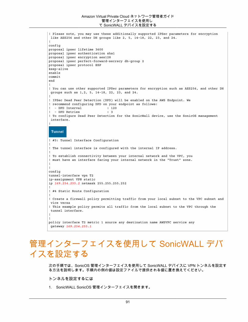
Amazon Virtual Private Cloud ネットワーク管理者ガイド管理インターフェイスを使用し
て SonicWALL デバイスを設定する
! Please note, you may use these additionally supported IPSec parameters for encryption like AES256 and other DH groups like 2, 5, 14-18, 22, 23, and 24.!configproposal ipsec lifetime 3600proposal ipsec authentication sha1proposal ipsec encryption aes128 proposal ipsec perfect-forward-secrecy dh-group 2proposal ipsec protocol ESPkeep-alive enable commit end!! You can use other supported IPSec parameters for encryption such as AES256, and other DH groups such as 1,2, 5, 14-18, 22, 23, and 24.!! IPSec Dead Peer Detection (DPD) will be enabled on the AWS Endpoint. We! recommend configuring DPD on your endpoint as follows:! - DPD Interval : 120! - DPD Retries : 3! To configure Dead Peer Detection for the SonicWall device, use the SonicOS management interface.!
! #3: Tunnel Interface Configuration! ! The tunnel interface is configured with the internal IP address.!! To establish connectivity between your internal network and the VPC, you! must have an interface facing your internal network in the "Trust" zone.!!configtunnel-interface vpn T2ip-assignment VPN staticip 169.254.255.2 netmask 255.255.255.252!! #4 Static Route Configuration!! Create a firewall policy permitting traffic from your local subnet to the VPC subnet and vice versa! This example policy permits all traffic from the local subnet to the VPC through the tunnel interface.!!policy interface T2 metric 1 source any destination name AWSVPC service any gateway 169.254.255.1
管理インターフェイスを使用して SonicWALL デバイスを設定する
次の手順では、SonicOS 管理インターフェイスを使用して SonicWALL デバイスに VPN トンネルを設定する方法を説明します。手順内の例の値は設定ファイルで提供される値に置き換えてください。
トンネルを設定するには
1. SonicWALL SonicOS 管理インターフェイスを開きます。
91
Amazon Virtual Private Cloud ネットワーク管理者ガイド管理インターフェイスを使用し
て SonicWALL デバイスを設定する
2. 左側のペインで、[VPN]、[Settings] の順に選択します。[VPN Policies] の下で、[Add...] を選択します。
3. [General] タブの VPN ポリシーウィンドウで、次の情報を入力します。
• [Policy Type]: [Site to Site] を選択します。• [Authentication Method]: [IKE using Preshared Secret] を選択します。• [Name]: VPN ポリシーの名前を入力します。設定ファイルに記載されている通り、VPN ID 名を使
用することをお勧めします。• IPsec Primary Gateway Name or Address: 設定ファイルに記載されている通り、仮想プライベート
ゲートウェイ (AWS エンドポイント) の IP アドレス (例: 72.21.209.193) を入力します。• IPsec Primary Gateway Name or Address: デフォルト値のままにします。• Shared Secret: 設定ファイルに記載されている通りに事前共有キーを入力後、[Confirm Shared
Secret] で再入力します。• Local IKE ID: カスタマーゲートウェイ (SonicWALL デバイス) の IPv4 アドレスを入力します。• Peer IKE ID: 仮想プライベートゲートウェイ (AWS エンドポイント) の IPv4 アドレスを入力しま
す。4. [Network] タブで、次の情報を入力します。
• [Local Networks] で、[Any address] を選択します。このオプションを使用して、ローカルネットワーク接続の問題を防ぐことをお勧めします。
• [Remote Networks] で、[Choose a destination network from list] を選択します。AWS 内に VPC のCIDR を持つアドレスオブジェクトを作成します。
5. [Proposals] タブで、次の情報を入力します。
• [IKE (Phase 1) Proposal] で、以下の作業を行います。• Exchange: [Main Mode] を選択します。• DH Group: Diffie-Hellman Group の値 (例: 2) を入力します。• Encryption: [AES-128] または [AES-256] を選択します。• Authentication: [SHA1] または [SHA256] を選択します。• Life Time: 28800 と入力します。
• [IKE (Phase 2) Proposal] で、以下の作業を行います。• Protocol: [ESP] を選択します。• Encryption: [AES-128] または [AES-256] を選択します。• Authentication: [SHA1] または [SHA256] を選択します。• [Enable Perfect Forward Secrecy] チェックボックスをオンにし、Diffie-Hellman group を選択しま
す。• Life Time: 3600 と入力します。
Important
仮想プライベートゲートウェイを作成したのが 2015 年 10 月より前の場合は、両方のフェーズで Diffie-Hellman group 2、AES-128、SHA1 を指定する必要があります。
6. [Advanced] タブで、次の情報を入力します。
• [Enable Keep Alive] を選択します。• [Enable Phase2 Dead Peer Detection] を選択し、次のように入力します。
• [Dead Peer Detection Interval] に、60 (SonicWALL デバイスで入力可能な最小値) と入力します。• [Failure Trigger Level] で、3 と入力します。
• [VPN Policy bound to] で、[Interface X1] を選択します。パブリック IP アドレスで一般的に指定されたインターフェイスです。
92
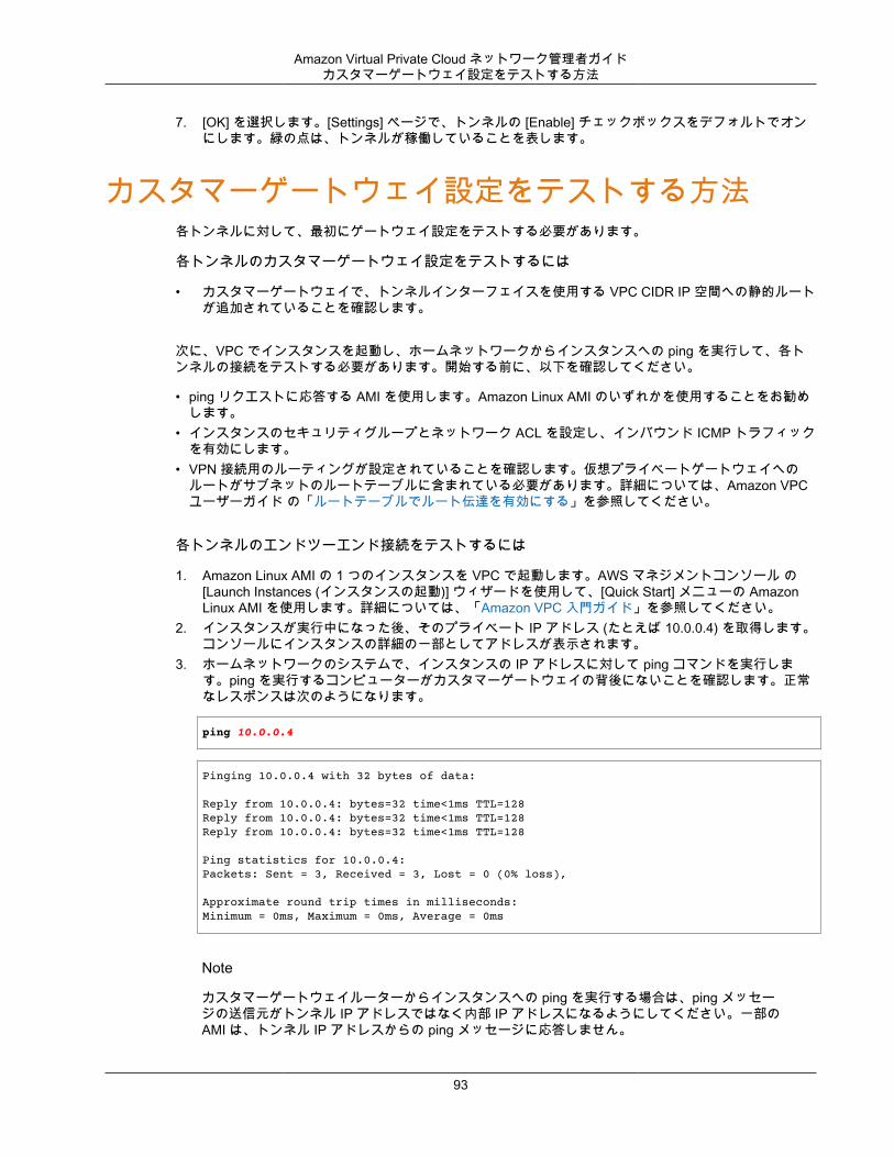
Amazon Virtual Private Cloud ネットワーク管理者ガイドカスタマーゲートウェイ設定をテストする方法
7. [OK] を選択します。[Settings] ページで、トンネルの [Enable] チェックボックスをデフォルトでオンにします。緑の点は、トンネルが稼働していることを表します。
カスタマーゲートウェイ設定をテストする方法各トンネルに対して、最初にゲートウェイ設定をテストする必要があります。
各トンネルのカスタマーゲートウェイ設定をテストするには
• カスタマーゲートウェイで、トンネルインターフェイスを使用する VPC CIDR IP 空間への静的ルートが追加されていることを確認します。
次に、VPC でインスタンスを起動し、ホームネットワークからインスタンスへの ping を実行して、各トンネルの接続をテストする必要があります。開始する前に、以下を確認してください。
• ping リクエストに応答する AMI を使用します。Amazon Linux AMI のいずれかを使用することをお勧めします。
• インスタンスのセキュリティグループとネットワーク ACL を設定し、インバウンド ICMP トラフィックを有効にします。
• VPN 接続用のルーティングが設定されていることを確認します。仮想プライベートゲートウェイへのルートがサブネットのルートテーブルに含まれている必要があります。詳細については、Amazon VPCユーザーガイド の「ルートテーブルでルート伝達を有効にする」を参照してください。
各トンネルのエンドツーエンド接続をテストするには
1. Amazon Linux AMI の 1 つのインスタンスを VPC で起動します。AWS マネジメントコンソール の[Launch Instances (インスタンスの起動)] ウィザードを使用して、[Quick Start] メニューの AmazonLinux AMI を使用します。詳細については、「Amazon VPC 入門ガイド」を参照してください。
2. インスタンスが実行中になった後、そのプライベート IP アドレス (たとえば 10.0.0.4) を取得します。コンソールにインスタンスの詳細の一部としてアドレスが表示されます。
3. ホームネットワークのシステムで、インスタンスの IP アドレスに対して ping コマンドを実行します。ping を実行するコンピューターがカスタマーゲートウェイの背後にないことを確認します。正常なレスポンスは次のようになります。
ping 10.0.0.4
Pinging 10.0.0.4 with 32 bytes of data:
Reply from 10.0.0.4: bytes=32 time<1ms TTL=128Reply from 10.0.0.4: bytes=32 time<1ms TTL=128Reply from 10.0.0.4: bytes=32 time<1ms TTL=128
Ping statistics for 10.0.0.4:Packets: Sent = 3, Received = 3, Lost = 0 (0% loss),
Approximate round trip times in milliseconds:Minimum = 0ms, Maximum = 0ms, Average = 0ms
Note
カスタマーゲートウェイルーターからインスタンスへの ping を実行する場合は、ping メッセージの送信元がトンネル IP アドレスではなく内部 IP アドレスになるようにしてください。一部のAMI は、トンネル IP アドレスからの ping メッセージに応答しません。
93

Amazon Virtual Private Cloud ネットワーク管理者ガイドカスタマーゲートウェイ設定をテストする方法
トンネルのテストを正常に実施できない場合は、「ボーダーゲートウェイプロトコルを使用した一般的なデバイスのカスタマーゲートウェイ接続のトラブルシューティング (p. 197)」を参照してください。
94
Amazon Virtual Private Cloud ネットワーク管理者ガイド
例: Fortinet Fortigate デバイストピック
• カスタマーゲートウェイの概要 (p. 96)• カスタマーゲートウェイの詳細と設定例 (p. 96)• カスタマーゲートウェイ設定をテストする方法 (p. 104)
次のトピックでは、お使いのカスタマーゲートウェイが Fortinet Fortigate 40+ デバイスである場合、統合チームより提供される設定情報の例をご覧いただけます。
2 つの図で設定例を紹介します。最初の図はカスタマーゲートウェイのレイアウトの概要を表し、2 番目の図はこの設定例の詳細を表しています。統合チームから受け取った実際の設定情報を使用して、カスタマーゲートウェイに適用する必要があります。
95
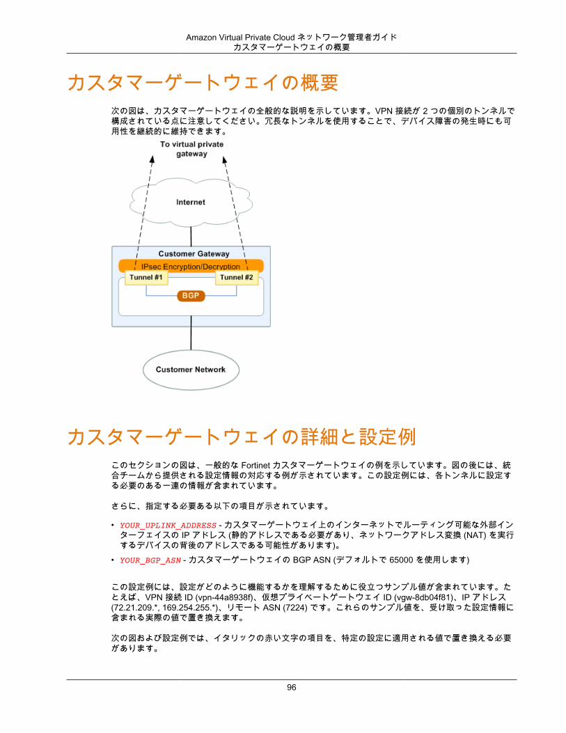
Amazon Virtual Private Cloud ネットワーク管理者ガイドカスタマーゲートウェイの概要
カスタマーゲートウェイの概要次の図は、カスタマーゲートウェイの全般的な説明を示しています。VPN 接続が 2 つの個別のトンネルで構成されている点に注意してください。冗長なトンネルを使用することで、デバイス障害の発生時にも可用性を継続的に維持できます。
カスタマーゲートウェイの詳細と設定例このセクションの図は、一般的な Fortinet カスタマーゲートウェイの例を示しています。図の後には、統合チームから提供される設定情報の対応する例が示されています。この設定例には、各トンネルに設定する必要のある一連の情報が含まれています。
さらに、指定する必要ある以下の項目が示されています。
• YOUR_UPLINK_ADDRESS - カスタマーゲートウェイ上のインターネットでルーティング可能な外部インターフェイスの IP アドレス (静的アドレスである必要があり、ネットワークアドレス変換 (NAT) を実行するデバイスの背後のアドレスである可能性があります)。
• YOUR_BGP_ASN - カスタマーゲートウェイの BGP ASN (デフォルトで 65000 を使用します)
この設定例には、設定がどのように機能するかを理解するために役立つサンプル値が含まれています。たとえば、VPN 接続 ID (vpn-44a8938f)、仮想プライベートゲートウェイ ID (vgw-8db04f81)、IP アドレス(72.21.209.*, 169.254.255.*)、リモート ASN (7224) です。これらのサンプル値を、受け取った設定情報に含まれる実際の値で置き換えます。
次の図および設定例では、イタリックの赤い文字の項目を、特定の設定に適用される値で置き換える必要があります。
96
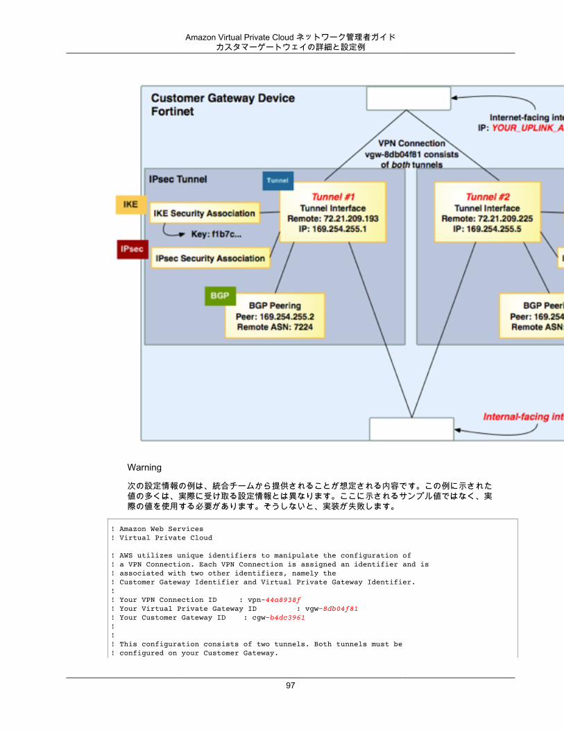
Amazon Virtual Private Cloud ネットワーク管理者ガイドカスタマーゲートウェイの詳細と設定例
Warning
次の設定情報の例は、統合チームから提供されることが想定される内容です。この例に示された値の多くは、実際に受け取る設定情報とは異なります。ここに示されるサンプル値ではなく、実際の値を使用する必要があります。そうしないと、実装が失敗します。
! Amazon Web Services! Virtual Private Cloud
! AWS utilizes unique identifiers to manipulate the configuration of ! a VPN Connection. Each VPN Connection is assigned an identifier and is ! associated with two other identifiers, namely the ! Customer Gateway Identifier and Virtual Private Gateway Identifier.!! Your VPN Connection ID : vpn-44a8938f! Your Virtual Private Gateway ID : vgw-8db04f81! Your Customer Gateway ID : cgw-b4dc3961!!! This configuration consists of two tunnels. Both tunnels must be ! configured on your Customer Gateway.
97
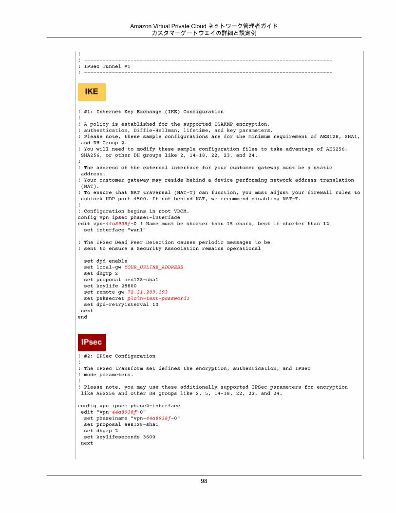
Amazon Virtual Private Cloud ネットワーク管理者ガイドカスタマーゲートウェイの詳細と設定例
!! --------------------------------------------------------------------------------! IPSec Tunnel #1! --------------------------------------------------------------------------------
! #1: Internet Key Exchange (IKE) Configuration!! A policy is established for the supported ISAKMP encryption, ! authentication, Diffie-Hellman, lifetime, and key parameters.! Please note, these sample configurations are for the minimum requirement of AES128, SHA1, and DH Group 2. ! You will need to modify these sample configuration files to take advantage of AES256, SHA256, or other DH groups like 2, 14-18, 22, 23, and 24. ! ! The address of the external interface for your customer gateway must be a static address. ! Your customer gateway may reside behind a device performing network address translation (NAT). ! To ensure that NAT traversal (NAT-T) can function, you must adjust your firewall rules to unblock UDP port 4500. If not behind NAT, we recommend disabling NAT-T. !! Configuration begins in root VDOM.config vpn ipsec phase1-interfaceedit vpn-44a8938f-0 ! Name must be shorter than 15 chars, best if shorter than 12 set interface "wan1"
! The IPSec Dead Peer Detection causes periodic messages to be ! sent to ensure a Security Association remains operational
set dpd enable set local-gw YOUR_UPLINK_ADDRESS set dhgrp 2 set proposal aes128-sha1 set keylife 28800 set remote-gw 72.21.209.193 set psksecret plain-text-password1 set dpd-retryinterval 10 nextend
! #2: IPSec Configuration! ! The IPSec transform set defines the encryption, authentication, and IPSec! mode parameters.!! Please note, you may use these additionally supported IPSec parameters for encryption like AES256 and other DH groups like 2, 5, 14-18, 22, 23, and 24.
config vpn ipsec phase2-interface edit "vpn-44a8938f-0" set phase1name "vpn-44a8938f-0" set proposal aes128-sha1 set dhgrp 2 set keylifeseconds 3600 next
98
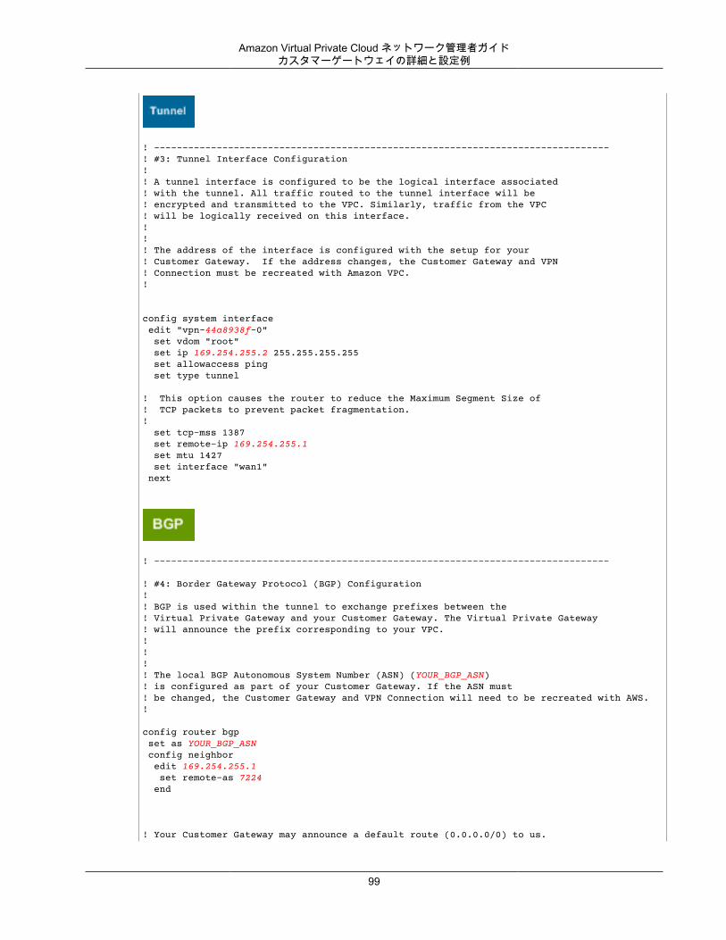
Amazon Virtual Private Cloud ネットワーク管理者ガイドカスタマーゲートウェイの詳細と設定例
! --------------------------------------------------------------------------------! #3: Tunnel Interface Configuration! ! A tunnel interface is configured to be the logical interface associated ! with the tunnel. All traffic routed to the tunnel interface will be ! encrypted and transmitted to the VPC. Similarly, traffic from the VPC! will be logically received on this interface.!!! The address of the interface is configured with the setup for your ! Customer Gateway. If the address changes, the Customer Gateway and VPN ! Connection must be recreated with Amazon VPC.!
config system interface edit "vpn-44a8938f-0" set vdom "root" set ip 169.254.255.2 255.255.255.255 set allowaccess ping set type tunnel
! This option causes the router to reduce the Maximum Segment Size of! TCP packets to prevent packet fragmentation.! set tcp-mss 1387 set remote-ip 169.254.255.1 set mtu 1427 set interface "wan1" next
! --------------------------------------------------------------------------------
! #4: Border Gateway Protocol (BGP) Configuration! ! BGP is used within the tunnel to exchange prefixes between the! Virtual Private Gateway and your Customer Gateway. The Virtual Private Gateway ! will announce the prefix corresponding to your VPC.! !!! The local BGP Autonomous System Number (ASN) (YOUR_BGP_ASN)! is configured as part of your Customer Gateway. If the ASN must ! be changed, the Customer Gateway and VPN Connection will need to be recreated with AWS.!
config router bgp set as YOUR_BGP_ASN config neighbor edit 169.254.255.1 set remote-as 7224 end
! Your Customer Gateway may announce a default route (0.0.0.0/0) to us.
99
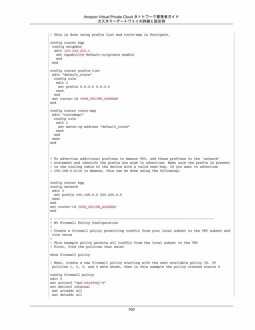
Amazon Virtual Private Cloud ネットワーク管理者ガイドカスタマーゲートウェイの詳細と設定例
! This is done using prefix list and route-map in Fortigate.
config router bgp config neighbor edit 169.254.255.1 set capability-default-originate enable end end
config router prefix-list edit "default_route" config rule edit 1 set prefix 0.0.0.0 0.0.0.0 next end set router-id YOUR_UPLINK_ADDRESSend
config router route-map edit "routemap1" config rule edit 1 set match-ip-address "default_route" next end nextend
! To advertise additional prefixes to Amazon VPC, add these prefixes to the 'network' ! statement and identify the prefix you wish to advertise. Make sure the prefix is present ! in the routing table of the device with a valid next-hop. If you want to advertise ! 192.168.0.0/16 to Amazon, this can be done using the following:
config router bgpconfig network edit 1 set prefix 192.168.0.0 255.255.0.0 nextendset router-id YOUR_UPLINK_ADDRESSend
! --------------------------------------------------------------------------------! #5 Firewall Policy Configuration!! Create a firewall policy permitting traffic from your local subnet to the VPC subnet and vice versa!! This example policy permits all traffic from the local subnet to the VPC! First, find the policies that exist
show firewall policy
! Next, create a new firewall policy starting with the next available policy ID. If policies 1, 2, 3, and 4 were shown, then in this example the policy created starts 5
config firewall policyedit 5set srcintf "vpn-44a8938f-0"set dstintf internal set srcaddr all set dstaddr all
100
Amazon Virtual Private Cloud ネットワーク管理者ガイドカスタマーゲートウェイの詳細と設定例
set action acceptset schedule always set service ANYnextend
config firewall policyedit 5set srcintf internalset dstintf "vpn-44a8938f-0" set srcaddr all set dstaddr allset action acceptset schedule always set service ANYnextend
! --------------------------------------------------------------------------------! IPSec Tunnel #2! --------------------------------------------------------------------------------! #1: Internet Key Exchange (IKE) Configuration!! A policy is established for the supported ISAKMP encryption, ! authentication, Diffie-Hellman, lifetime, and key parameters.!! The address of the external interface for your customer gateway must be a static address. ! Your customer gateway may reside behind a device performing network address translation (NAT). ! To ensure that NAT traversal (NAT-T) can function, you must adjust your firewall rules to unblock UDP port 4500. If not behind NAT, we recommend disabling NAT-T. !! Configuration begins in root VDOM.config vpn ipsec phase1-interfaceedit vpn-44a8938f-1 ! Name must be shorter than 15 chars, best if shorter than 12 set interface "wan1"
! The IPSec Dead Peer Detection causes periodic messages to be ! sent to ensure a Security Association remains operational
set dpd enable set local-gw YOUR_UPLINK_ADDRESS set dhgrp 2 set proposal aes128-sha1 set keylife 28800 set remote-gw 72.21.209.225 set psksecret plain-text-password2 set dpd-retryinterval 10 nextend
! #2: IPSec Configuration! ! The IPSec transform set defines the encryption, authentication, and IPSec
101
Amazon Virtual Private Cloud ネットワーク管理者ガイドカスタマーゲートウェイの詳細と設定例
! mode parameters.!! Please note, you may use these additionally supported IPSec parameters for encryption like AES256 and other DH groups like 2, 5, 14-18, 22, 23, and 24.
config vpn ipsec phase2-interface edit "vpn-44a8938f-1" set phase1name "vpn-44a8938f-1" set proposal aes128-sha1 set dhgrp 2 set keylifeseconds 3600 next
! --------------------------------------------------------------------------------! #3: Tunnel Interface Configuration! ! A tunnel interface is configured to be the logical interface associated ! with the tunnel. All traffic routed to the tunnel interface will be ! encrypted and transmitted to the VPC. Similarly, traffic from the VPC! will be logically received on this interface.!!! The address of the interface is configured with the setup for your ! Customer Gateway. If the address changes, the Customer Gateway and VPN ! Connection must be recreated with Amazon VPC.!
config system interface edit "vpn-44a8938f-1" set vdom "root" set ip 169.254.255.6 255.255.255.255 set allowaccess ping set type tunnel
! This option causes the router to reduce the Maximum Segment Size of! TCP packets to prevent packet fragmentation.! set tcp-mss 1387 set remote-ip 169.254.255.5 set mtu 1427 set interface "wan1" next
! --------------------------------------------------------------------------------
! #4: Border Gateway Protocol (BGP) Configuration! ! BGP is used within the tunnel to exchange prefixes between the! Virtual Private Gateway and your Customer Gateway. The Virtual Private Gateway ! will announce the prefix corresponding to your VPC.! !!! The local BGP Autonomous System Number (ASN) (YOUR_BGP_ASN)! is configured as part of your Customer Gateway. If the ASN must
102
Amazon Virtual Private Cloud ネットワーク管理者ガイドカスタマーゲートウェイの詳細と設定例
! be changed, the Customer Gateway and VPN Connection will need to be recreated with AWS.!
config router bgp set as YOUR_BGP_ASN config neighbor edit 169.254.255.5 set remote-as 7224 end
! Your Customer Gateway may announce a default route (0.0.0.0/0) to us. ! This is done using prefix list and route-map in Fortigate.
config router bgp config neighbor edit 169.254.255.5 set capability-default-originate enable end end
config router prefix-list edit "default_route" config rule edit 1 set prefix 0.0.0.0 0.0.0.0 next end set router-id YOUR_UPLINK_ADDRESSend
config router route-map edit "routemap1" config rule edit 1 set match-ip-address "default_route" next end nextend
! To advertise additional prefixes to Amazon VPC, add these prefixes to the 'network' ! statement and identify the prefix you wish to advertise. Make sure the prefix is present ! in the routing table of the device with a valid next-hop. If you want to advertise ! 192.168.0.0/16 to Amazon, this can be done using the following:
config router bgpconfig network edit 1 set prefix 192.168.0.0 255.255.0.0 nextendset router-id YOUR_UPLINK_ADDRESSend
!! --------------------------------------------------------------------------------! #5 Firewall Policy Configuration!! Create a firewall policy permitting traffic from your local subnet to the VPC subnet and vice versa!
103
Amazon Virtual Private Cloud ネットワーク管理者ガイドカスタマーゲートウェイ設定をテストする方法
! This example policy permits all traffic from the local subnet to the VPC! First, find the policies that exist
show firewall policy
! Next, create a new firewall policy starting with the next available policy ID. If policies 1, 2, 3, and 4 were shown, then in this example the policy created starts 5
config firewall policyedit 5set srcintf "vpn-44a8938f-1"set dstintf internal set srcaddr all set dstaddr allset action acceptset schedule always set service ANYnextend
config firewall policyedit 5set srcintf internalset dstintf "vpn-44a8938f-1" set srcaddr all set dstaddr allset action acceptset schedule always set service ANYnextend
! --------------------------------------------------------------------------------
カスタマーゲートウェイ設定をテストする方法各トンネルに対して、ゲートウェイ設定をテストすることができます。
各トンネルのカスタマーゲートウェイ設定をテストするには
1. カスタマーゲートウェイで、BGP ステータスが Active であるかどうかを確認します。
BGP ピアがアクティブになるまでに約 30 秒かかります。2. カスタマーゲートウェイが仮想プライベートゲートウェイへのルートをアドバタイズしていることを
確認します。このルートは、デフォルトルート (0.0.0.0/0) の場合と、任意で特定したルートの場合があります。
正しく設定されている場合、BGP ピアは、VPC 統合チームが VPC 用に指定したプレフィックス (たとえば、10.0.0.0/24) に対応する仮想プライベートゲートウェイから 1 つのルートを受け取ります。BGPピアが確立された場合は、プレフィックスを受け取り、プレフィックスをアドバタイズして、トンネルが正しく設定されます。両方のトンネルがこの状態であることを確認します。
次に、VPC でインスタンスを起動し、ホームネットワークからインスタンスへの ping を実行して、各トンネルの接続をテストする必要があります。開始する前に、以下を確認してください。
• ping リクエストに応答する AMI を使用します。Amazon Linux AMI のいずれかを使用することをお勧めします。
104
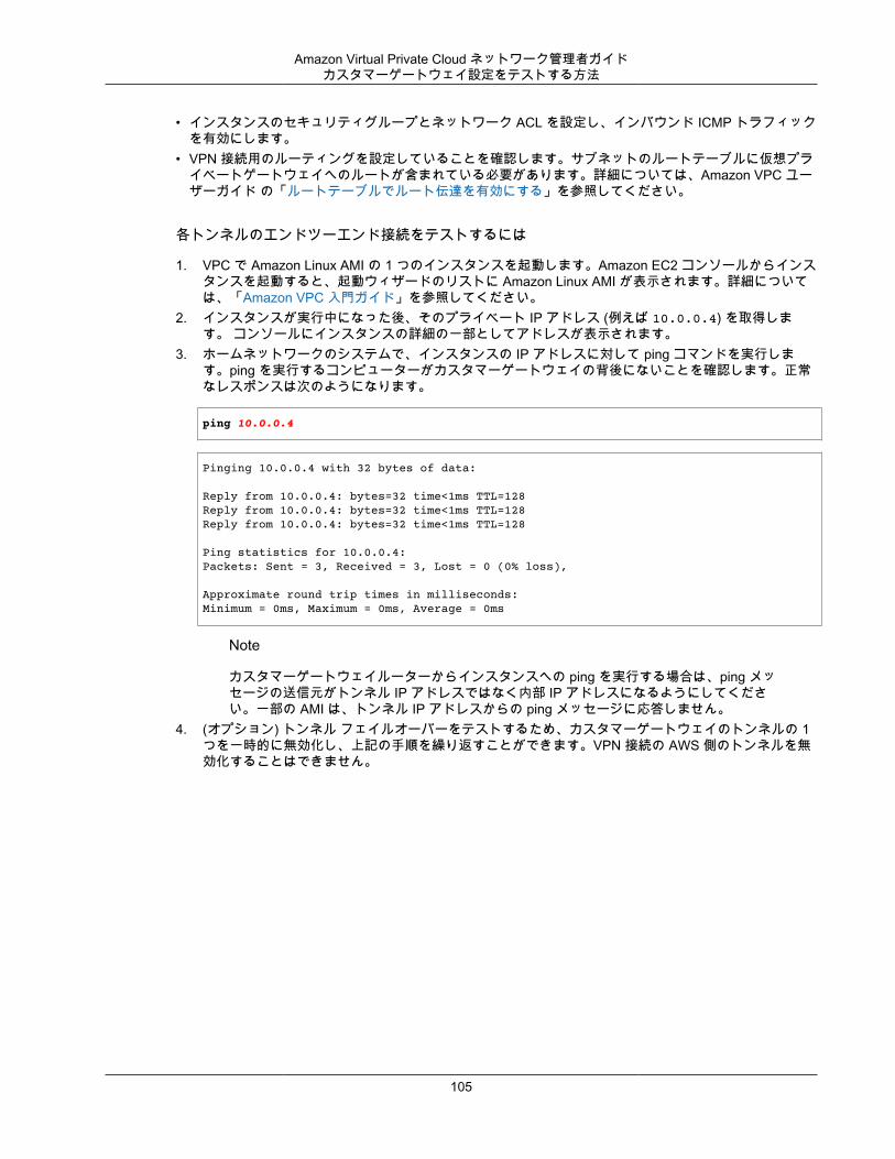
Amazon Virtual Private Cloud ネットワーク管理者ガイドカスタマーゲートウェイ設定をテストする方法
• インスタンスのセキュリティグループとネットワーク ACL を設定し、インバウンド ICMP トラフィックを有効にします。
• VPN 接続用のルーティングを設定していることを確認します。サブネットのルートテーブルに仮想プライベートゲートウェイへのルートが含まれている必要があります。詳細については、Amazon VPC ユーザーガイド の「ルートテーブルでルート伝達を有効にする」を参照してください。
各トンネルのエンドツーエンド接続をテストするには
1. VPC で Amazon Linux AMI の 1 つのインスタンスを起動します。Amazon EC2 コンソールからインスタンスを起動すると、起動ウィザードのリストに Amazon Linux AMI が表示されます。詳細については、「Amazon VPC 入門ガイド」を参照してください。
2. インスタンスが実行中になった後、そのプライベート IP アドレス (例えば 10.0.0.4) を取得します。 コンソールにインスタンスの詳細の一部としてアドレスが表示されます。
3. ホームネットワークのシステムで、インスタンスの IP アドレスに対して ping コマンドを実行します。ping を実行するコンピューターがカスタマーゲートウェイの背後にないことを確認します。正常なレスポンスは次のようになります。
ping 10.0.0.4
Pinging 10.0.0.4 with 32 bytes of data:
Reply from 10.0.0.4: bytes=32 time<1ms TTL=128Reply from 10.0.0.4: bytes=32 time<1ms TTL=128Reply from 10.0.0.4: bytes=32 time<1ms TTL=128
Ping statistics for 10.0.0.4:Packets: Sent = 3, Received = 3, Lost = 0 (0% loss),
Approximate round trip times in milliseconds:Minimum = 0ms, Maximum = 0ms, Average = 0ms
Note
カスタマーゲートウェイルーターからインスタンスへの ping を実行する場合は、ping メッセージの送信元がトンネル IP アドレスではなく内部 IP アドレスになるようにしてください。一部の AMI は、トンネル IP アドレスからの ping メッセージに応答しません。
4. (オプション) トンネル フェイルオーバーをテストするため、カスタマーゲートウェイのトンネルの 1つを一時的に無効化し、上記の手順を繰り返すことができます。VPN 接続の AWS 側のトンネルを無効化することはできません。
105
Amazon Virtual Private Cloud ネットワーク管理者ガイド
例: Juniper J-Series JunOS デバイストピック
• カスタマーゲートウェイの概要 (p. 107)• カスタマーゲートウェイの詳細と設定例 (p. 108)• カスタマーゲートウェイ設定をテストする方法 (p. 114)
このセクションでは、JunOS 9.5 (またはそれ以降の) ソフトウェアを実行している Juniper J-Series ルーターをカスタマーゲートウェイとして使用する場合に、統合チームから提供される設定情報の例について説明します。
2 つの図で設定例を紹介します。最初の図はカスタマーゲートウェイのレイアウトの概要を表し、2 番目の図はこの設定例の詳細を表しています。統合チームから受け取った実際の設定情報を使用して、カスタマーゲートウェイに適用する必要があります。
106
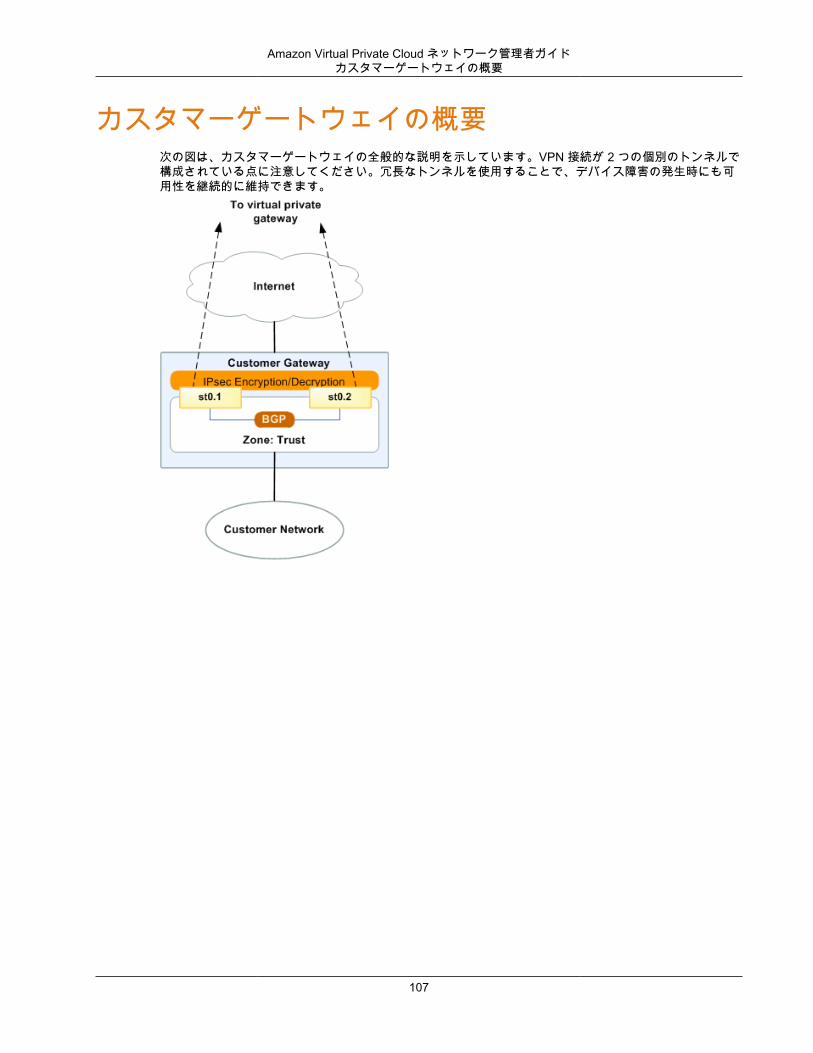
Amazon Virtual Private Cloud ネットワーク管理者ガイドカスタマーゲートウェイの概要
カスタマーゲートウェイの概要次の図は、カスタマーゲートウェイの全般的な説明を示しています。VPN 接続が 2 つの個別のトンネルで構成されている点に注意してください。冗長なトンネルを使用することで、デバイス障害の発生時にも可用性を継続的に維持できます。
107
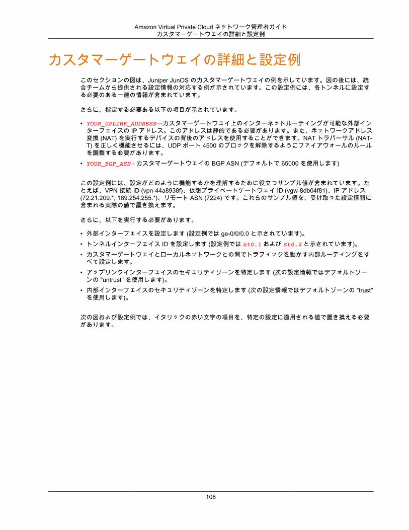
Amazon Virtual Private Cloud ネットワーク管理者ガイドカスタマーゲートウェイの詳細と設定例
カスタマーゲートウェイの詳細と設定例このセクションの図は、Juniper JunOS のカスタマーゲートウェイの例を示しています。図の後には、統合チームから提供される設定情報の対応する例が示されています。この設定例には、各トンネルに設定する必要のある一連の情報が含まれています。
さらに、指定する必要ある以下の項目が示されています。
• YOUR_UPLINK_ADDRESS—カスタマーゲートウェイ上のインターネットルーティングが可能な外部インターフェイスの IP アドレス。このアドレスは静的である必要があります。また、ネットワークアドレス変換 (NAT) を実行するデバイスの背後のアドレスを使用することができます。NAT トラバーサル (NAT-T) を正しく機能させるには、UDP ポート 4500 のブロックを解除するようにファイアウォールのルールを調整する必要があります。
• YOUR_BGP_ASN - カスタマーゲートウェイの BGP ASN (デフォルトで 65000 を使用します)
この設定例には、設定がどのように機能するかを理解するために役立つサンプル値が含まれています。たとえば、VPN 接続 ID (vpn-44a8938f)、仮想プライベートゲートウェイ ID (vgw-8db04f81)、IP アドレス(72.21.209.*, 169.254.255.*)、リモート ASN (7224) です。これらのサンプル値を、受け取った設定情報に含まれる実際の値で置き換えます。
さらに、以下を実行する必要があります。
• 外部インターフェイスを設定します (設定例では ge-0/0/0.0 と示されています)。• トンネルインターフェイス ID を設定します (設定例では st0.1 および st0.2 と示されています)。• カスタマーゲートウェイとローカルネットワークとの間でトラフィックを動かす内部ルーティングをす
べて設定します。• アップリンクインターフェイスのセキュリティゾーンを特定します (次の設定情報ではデフォルトゾー
ンの "untrust" を使用します)。• 内部インターフェイスのセキュリティゾーンを特定します (次の設定情報ではデフォルトゾーンの "trust"
を使用します)。
次の図および設定例では、イタリックの赤い文字の項目を、特定の設定に適用される値で置き換える必要があります。
108
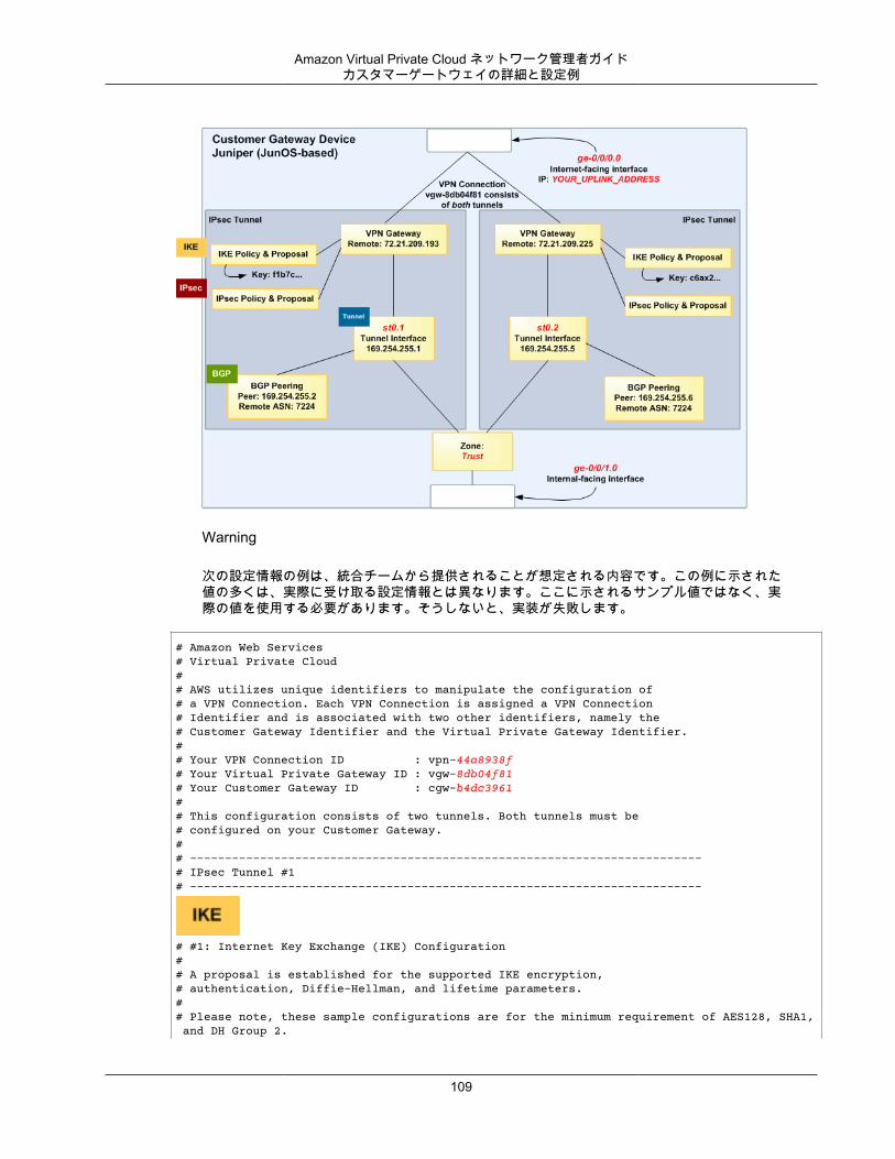
Amazon Virtual Private Cloud ネットワーク管理者ガイドカスタマーゲートウェイの詳細と設定例
Warning
次の設定情報の例は、統合チームから提供されることが想定される内容です。この例に示された値の多くは、実際に受け取る設定情報とは異なります。ここに示されるサンプル値ではなく、実際の値を使用する必要があります。そうしないと、実装が失敗します。
# Amazon Web Services# Virtual Private Cloud## AWS utilizes unique identifiers to manipulate the configuration of # a VPN Connection. Each VPN Connection is assigned a VPN Connection # Identifier and is associated with two other identifiers, namely the # Customer Gateway Identifier and the Virtual Private Gateway Identifier.## Your VPN Connection ID : vpn-44a8938f# Your Virtual Private Gateway ID : vgw-8db04f81# Your Customer Gateway ID : cgw-b4dc3961## This configuration consists of two tunnels. Both tunnels must be # configured on your Customer Gateway.## -------------------------------------------------------------------------# IPsec Tunnel #1# -------------------------------------------------------------------------
# #1: Internet Key Exchange (IKE) Configuration## A proposal is established for the supported IKE encryption, # authentication, Diffie-Hellman, and lifetime parameters.## Please note, these sample configurations are for the minimum requirement of AES128, SHA1, and DH Group 2.
109
Amazon Virtual Private Cloud ネットワーク管理者ガイドカスタマーゲートウェイの詳細と設定例
# You will need to modify these sample configuration files to take advantage of AES256, SHA256, or other DH groups like 2, 14-18, 22, 23, and 24.# The address of the external interface for your customer gateway must be a static address. # To ensure that NAT traversal (NAT-T) can function, you must adjust your firewall rules to unblock UDP port 4500. If not behind NAT, we recommend disabling NAT-T.#set security ike proposal ike-prop-vpn-44a8938f-1 authentication-method pre-shared-keys set security ike proposal ike-prop-vpn-44a8938f-1 authentication-algorithm sha1set security ike proposal ike-prop-vpn-44a8938f-1 encryption-algorithm aes-128-cbcset security ike proposal ike-prop-vpn-44a8938f-1 lifetime-seconds 28800set security ike proposal ike-prop-vpn-44a8938f-1 dh-group group2
# An IKE policy is established to associate a Pre Shared Key with the # defined proposal.#set security ike policy ike-pol-vpn-44a8938f-1 mode main set security ike policy ike-pol-vpn-44a8938f-1 proposals ike-prop-vpn-44a8938f-0set security ike policy ike-pol-vpn-44a8938f-1 pre-shared-key ascii-text plain-text-password1
# The IKE gateway is defined to be the Virtual Private Gateway. The gateway # configuration associates a local interface, remote IP address, and# IKE policy.## This example shows the outside of the tunnel as interface ge-0/0/0.0.# This should be set to the interface that IP address YOUR_UPLINK_ADDRESS is# associated with.# This address is configured with the setup for your Customer Gateway.## If the address changes, the Customer Gateway and VPN Connection must # be recreated.set security ike gateway gw-vpn-44a8938f-1 ike-policy ike-pol-vpn-44a8938f-0set security ike gateway gw-vpn-44a8938f-1 external-interface ge-0/0/0.0set security ike gateway gw-vpn-44a8938f-1 address 72.21.209.225
# Troubleshooting IKE connectivity can be aided by enabling IKE tracing.# The configuration below will cause the router to log IKE messages to# the 'kmd' log. Run 'show messages kmd' to retrieve these logs.# set security ike traceoptions file kmd# set security ike traceoptions file size 1024768# set security ike traceoptions file files 10# set security ike traceoptions flag all
# #2: IPsec Configuration## The IPsec proposal defines the protocol, authentication, encryption, and# lifetime parameters for our IPsec security association.# Please note, you may use these additionally supported IPSec parameters for encryption like AES256 and other DH groups like 2, 5, 14-18, 22, 23, and 24. #set security ipsec proposal ipsec-prop-vpn-44a8938f-1 protocol espset security ipsec proposal ipsec-prop-vpn-44a8938f-1 authentication-algorithm hmac-sha1-96set security ipsec proposal ipsec-prop-vpn-44a8938f-1 encryption-algorithm aes-128-cbcset security ipsec proposal ipsec-prop-vpn-44a8938f-1 lifetime-seconds 3600
# The IPsec policy incorporates the Diffie-Hellman group and the IPsec# proposal.#set security ipsec policy ipsec-pol-vpn-44a8938f-1 perfect-forward-secrecy keys group2set security ipsec policy ipsec-pol-vpn-44a8938f-1 proposals ipsec-prop-vpn-44a8938f-0
110
Amazon Virtual Private Cloud ネットワーク管理者ガイドカスタマーゲートウェイの詳細と設定例
# A security association is defined here. The IPsec Policy and IKE gateways# are associated with a tunnel interface (st0.1).# The tunnel interface ID is assumed; if other tunnels are defined on# your router, you will need to specify a unique interface name # (for example, st0.10).#set security ipsec vpn vpn-44a8938f-1 bind-interface st0.1set security ipsec vpn vpn-44a8938f-1 ike gateway gw-vpn-44a8938f-0set security ipsec vpn vpn-44a8938f-1 ike ipsec-policy ipsec-pol-vpn-44a8938f-0set security ipsec vpn vpn-44a8938f-1 df-bit clear
# This option enables IPsec Dead Peer Detection, which causes periodic# messages to be sent to ensure a Security Association remains operational.#set security ike gateway gw-vpn-44a8938f-1 dead-peer-detection
# #3: Tunnel Interface Configuration#
# The tunnel interface is configured with the internal IP address.#set interfaces st0.1 family inet address 169.254.255.2/30set interfaces st0.1 family inet mtu 1436set security zones security-zone trust interfaces st0.1
# The security zone protecting external interfaces of the router must be # configured to allow IKE traffic inbound.#set security zones security-zone untrust host-inbound-traffic system-services ike
# The security zone protecting internal interfaces (including the logical # tunnel interfaces) must be configured to allow BGP traffic inbound.#set security zones security-zone trust host-inbound-traffic protocols bgp
# This option causes the router to reduce the Maximum Segment Size of# TCP packets to prevent packet fragmentation.#set security flow tcp-mss ipsec-vpn mss 1387
# #4: Border Gateway Protocol (BGP) Configuration# # BGP is used within the tunnel to exchange prefixes between the# Virtual Private Gateway and your Customer Gateway. The Virtual Private Gateway # will announce the prefix corresponding to your VPC.# # Your Customer Gateway may announce a default route (0.0.0.0/0), # which can be done with the EXPORT-DEFAULT policy.## To advertise additional prefixes to Amazon VPC, add additional prefixes to the "default" term# EXPORT-DEFAULT policy. Make sure the prefix is present in the routing table of the device with # a valid next-hop.# # The BGP timers are adjusted to provide more rapid detection of outages. # # The local BGP Autonomous System Number (ASN) (YOUR_BGP_ASN) is configured# as part of your Customer Gateway. If the ASN must be changed, the
111
Amazon Virtual Private Cloud ネットワーク管理者ガイドカスタマーゲートウェイの詳細と設定例
# Customer Gateway and VPN Connection will need to be recreated with AWS.## We establish a basic route policy to export a default route to the# Virtual Private Gateway. #set policy-options policy-statement EXPORT-DEFAULT term default from route-filter 0.0.0.0/0 exact set policy-options policy-statement EXPORT-DEFAULT term default then accept set policy-options policy-statement EXPORT-DEFAULT term reject then reject
set protocols bgp group ebgp type external
set protocols bgp group ebgp neighbor 169.254.255.1 export EXPORT-DEFAULT set protocols bgp group ebgp neighbor 169.254.255.1 peer-as 7224set protocols bgp group ebgp neighbor 169.254.255.1 hold-time 30set protocols bgp group ebgp neighbor 169.254.255.1 local-as YOUR_BGP_ASN # -------------------------------------------------------------------------# IPsec Tunnel #2# -------------------------------------------------------------------------
# #1: Internet Key Exchange (IKE) Configuration## A proposal is established for the supported IKE encryption, # authentication, Diffie-Hellman, and lifetime parameters.# Please note, these sample configurations are for the minimum requirement of AES128, SHA1, and DH Group 2.# You will need to modify these sample configuration files to take advantage of AES256, SHA256, or other DH groups like 2, 14-18, 22, 23, and 24.# The address of the external interface for your customer gateway must be a static address. # To ensure that NAT traversal (NAT-T) can function, you must adjust your firewall rules to unblock UDP port 4500. If not behind NAT, we recommend disabling NAT-T.#set security ike proposal ike-prop-vpn-44a8938f-2 authentication-method pre-shared-keys set security ike proposal ike-prop-vpn-44a8938f-2 authentication-algorithm sha1set security ike proposal ike-prop-vpn-44a8938f-2 encryption-algorithm aes-128-cbcset security ike proposal ike-prop-vpn-44a8938f-2 lifetime-seconds 28800set security ike proposal ike-prop-vpn-44a8938f-2 dh-group group2
# An IKE policy is established to associate a Pre Shared Key with the # defined proposal.#set security ike policy ike-pol-vpn-44a8938f-2 mode main set security ike policy ike-pol-vpn-44a8938f-2 proposals ike-prop-vpn-44a8938f-2set security ike policy ike-pol-vpn-44a8938f-2 pre-shared-key ascii-text plain-text-password2
# The IKE gateway is defined to be the Virtual Private Gateway. The gateway # configuration associates a local interface, remote IP address, and# IKE policy.## This example shows the outside of the tunnel as interface ge-0/0/0.0.# This should be set to the interface that IP address YOUR_UPLINK_ADDRESS is# associated with.# This address is configured with the setup for your Customer Gateway.## If the address changes, the Customer Gateway and VPN Connection must be recreated.#set security ike gateway gw-vpn-44a8938f-2 ike-policy ike-pol-vpn-44a8938f-1set security ike gateway gw-vpn-44a8938f-2 external-interface ge-0/0/0.0set security ike gateway gw-vpn-44a8938f-2 address 72.21.209.193
112
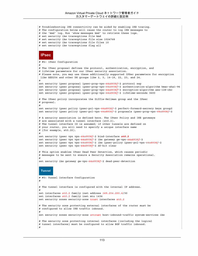
Amazon Virtual Private Cloud ネットワーク管理者ガイドカスタマーゲートウェイの詳細と設定例
# Troubleshooting IKE connectivity can be aided by enabling IKE tracing.# The configuration below will cause the router to log IKE messages to# the 'kmd' log. Run 'show messages kmd' to retrieve these logs.# set security ike traceoptions file kmd# set security ike traceoptions file size 1024768# set security ike traceoptions file files 10# set security ike traceoptions flag all
# #2: IPsec Configuration## The IPsec proposal defines the protocol, authentication, encryption, and# lifetime parameters for our IPsec security association.# Please note, you may use these additionally supported IPSec parameters for encryption like AES256 and other DH groups like 2, 5, 14-18, 22, 23, and 24. #set security ipsec proposal ipsec-prop-vpn-44a8938f-2 protocol espset security ipsec proposal ipsec-prop-vpn-44a8938f-2 authentication-algorithm hmac-sha1-96set security ipsec proposal ipsec-prop-vpn-44a8938f-2 encryption-algorithm aes-128-cbcset security ipsec proposal ipsec-prop-vpn-44a8938f-2 lifetime-seconds 3600
# The IPsec policy incorporates the Diffie-Hellman group and the IPsec# proposal.#set security ipsec policy ipsec-pol-vpn-44a8938f-2 perfect-forward-secrecy keys group2set security ipsec policy ipsec-pol-vpn-44a8938f-2 proposals ipsec-prop-vpn-44a8938f-2
# A security association is defined here. The IPsec Policy and IKE gateways# are associated with a tunnel interface (st0.2).# The tunnel interface ID is assumed; if other tunnels are defined on# your router, you will need to specify a unique interface name # (for example, st0.20).#set security ipsec vpn vpn-44a8938f-2 bind-interface st0.2set security ipsec vpn vpn-44a8938f-2 ike gateway gw-vpn-44a8938f-2set security ipsec vpn vpn-44a8938f-2 ike ipsec-policy ipsec-pol-vpn-44a8938f-2set security ipsec vpn vpn-44a8938f-2 df-bit clear
# This option enables IPsec Dead Peer Detection, which causes periodic# messages to be sent to ensure a Security Association remains operational.#set security ike gateway gw-vpn-44a8938f-2 dead-peer-detection
# #3: Tunnel Interface Configuration#
# The tunnel interface is configured with the internal IP address.#set interfaces st0.2 family inet address 169.254.255.6/30set interfaces st0.2 family inet mtu 1436set security zones security-zone trust interfaces st0.2
# The security zone protecting external interfaces of the router must be # configured to allow IKE traffic inbound.#set security zones security-zone untrust host-inbound-traffic system-services ike
# The security zone protecting internal interfaces (including the logical # tunnel interfaces) must be configured to allow BGP traffic inbound.#
113
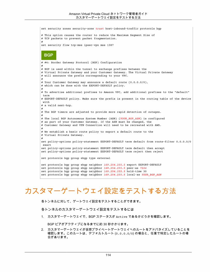
Amazon Virtual Private Cloud ネットワーク管理者ガイドカスタマーゲートウェイ設定をテストする方法
set security zones security-zone trust host-inbound-traffic protocols bgp
# This option causes the router to reduce the Maximum Segment Size of# TCP packets to prevent packet fragmentation.#set security flow tcp-mss ipsec-vpn mss 1387
# #4: Border Gateway Protocol (BGP) Configuration# # BGP is used within the tunnel to exchange prefixes between the# Virtual Private Gateway and your Customer Gateway. The Virtual Private Gateway # will announce the prefix corresponding to your VPC.# # Your Customer Gateway may announce a default route (0.0.0.0/0), # which can be done with the EXPORT-DEFAULT policy.## To advertise additional prefixes to Amazon VPC, add additional prefixes to the "default" term# EXPORT-DEFAULT policy. Make sure the prefix is present in the routing table of the device with # a valid next-hop.# # The BGP timers are adjusted to provide more rapid detection of outages. # # The local BGP Autonomous System Number (ASN) (YOUR_BGP_ASN) is configured# as part of your Customer Gateway. If the ASN must be changed, the # Customer Gateway and VPN Connection will need to be recreated with AWS.## We establish a basic route policy to export a default route to the# Virtual Private Gateway. #set policy-options policy-statement EXPORT-DEFAULT term default from route-filter 0.0.0.0/0 exact set policy-options policy-statement EXPORT-DEFAULT term default then accept set policy-options policy-statement EXPORT-DEFAULT term reject then reject
set protocols bgp group ebgp type external
set protocols bgp group ebgp neighbor 169.254.255.5 export EXPORT-DEFAULT set protocols bgp group ebgp neighbor 169.254.255.5 peer-as 7224set protocols bgp group ebgp neighbor 169.254.255.5 hold-time 30set protocols bgp group ebgp neighbor 169.254.255.5 local-as YOUR_BGP_ASN
カスタマーゲートウェイ設定をテストする方法各トンネルに対して、ゲートウェイ設定をテストすることができます。
各トンネルのカスタマーゲートウェイ設定をテストするには
1. カスタマーゲートウェイで、BGP ステータスが Active であるかどうかを確認します。
BGP ピアがアクティブになるまでに約 30 秒かかります。2. カスタマーゲートウェイが仮想プライベートゲートウェイへのルートをアドバタイズしていることを
確認します。このルートは、デフォルトルート (0.0.0.0/0) の場合と、任意で特定したルートの場合があります。
114
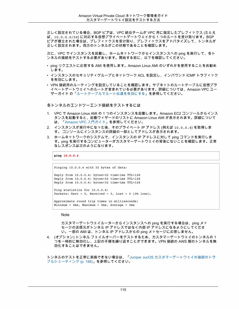
Amazon Virtual Private Cloud ネットワーク管理者ガイドカスタマーゲートウェイ設定をテストする方法
正しく設定されている場合、BGP ピアは、VPC 統合チームが VPC 用に指定したプレフィックス (たとえば、10.0.0.0/24) に対応する仮想プライベートゲートウェイから 1 つのルートを受け取ります。BGPピアが確立された場合は、プレフィックスを受け取り、プレフィックスをアドバタイズして、トンネルが正しく設定されます。両方のトンネルがこの状態であることを確認します。
次に、VPC でインスタンスを起動し、ホームネットワークからインスタンスへの ping を実行して、各トンネルの接続をテストする必要があります。開始する前に、以下を確認してください。
• ping リクエストに応答する AMI を使用します。Amazon Linux AMI のいずれかを使用することをお勧めします。
• インスタンスのセキュリティグループとネットワーク ACL を設定し、インバウンド ICMP トラフィックを有効にします。
• VPN 接続用のルーティングを設定していることを確認します。サブネットのルートテーブルに仮想プライベートゲートウェイへのルートが含まれている必要があります。詳細については、Amazon VPC ユーザーガイド の「ルートテーブルでルート伝達を有効にする」を参照してください。
各トンネルのエンドツーエンド接続をテストするには
1. VPC で Amazon Linux AMI の 1 つのインスタンスを起動します。Amazon EC2 コンソールからインスタンスを起動すると、起動ウィザードのリストに Amazon Linux AMI が表示されます。詳細については、「Amazon VPC 入門ガイド」を参照してください。
2. インスタンスが実行中になった後、そのプライベート IP アドレス (例えば 10.0.0.4) を取得します。 コンソールにインスタンスの詳細の一部としてアドレスが表示されます。
3. ホームネットワークのシステムで、インスタンスの IP アドレスに対して ping コマンドを実行します。ping を実行するコンピューターがカスタマーゲートウェイの背後にないことを確認します。正常なレスポンスは次のようになります。
ping 10.0.0.4
Pinging 10.0.0.4 with 32 bytes of data:
Reply from 10.0.0.4: bytes=32 time<1ms TTL=128Reply from 10.0.0.4: bytes=32 time<1ms TTL=128Reply from 10.0.0.4: bytes=32 time<1ms TTL=128
Ping statistics for 10.0.0.4:Packets: Sent = 3, Received = 3, Lost = 0 (0% loss),
Approximate round trip times in milliseconds:Minimum = 0ms, Maximum = 0ms, Average = 0ms
Note
カスタマーゲートウェイルーターからインスタンスへの ping を実行する場合は、ping メッセージの送信元がトンネル IP アドレスではなく内部 IP アドレスになるようにしてください。一部の AMI は、トンネル IP アドレスからの ping メッセージに応答しません。
4. (オプション) トンネル フェイルオーバーをテストするため、カスタマーゲートウェイのトンネルの 1つを一時的に無効化し、上記の手順を繰り返すことができます。VPN 接続の AWS 側のトンネルを無効化することはできません。
トンネルのテストを正常に実施できない場合は、「Juniper JunOS カスタマーゲートウェイの接続のトラブルシューティング (p. 188)」を参照してください。
115
Amazon Virtual Private Cloud ネットワーク管理者ガイド
例: Juniper SRX JunOS デバイストピック
• カスタマーゲートウェイの概要 (p. 117)• カスタマーゲートウェイの詳細と設定例 (p. 118)• カスタマーゲートウェイ設定をテストする方法 (p. 124)
このセクションでは、JunOS 11.0 (またはそれ以降の) ソフトウェアを搭載している Juniper SRX ルーターをカスタマーゲートウェイとして使用する場合に、統合チームから提供される設定情報の例について説明します。
2 つの図で設定例を紹介します。最初の図はカスタマーゲートウェイのレイアウトの概要を表し、2 番目の図はこの設定例の詳細を表しています。統合チームから受け取った実際の設定情報を使用して、カスタマーゲートウェイに適用する必要があります。
116

Amazon Virtual Private Cloud ネットワーク管理者ガイドカスタマーゲートウェイの概要
カスタマーゲートウェイの概要次の図は、カスタマーゲートウェイの全般的な説明を示しています。VPN 接続が 2 つの個別のトンネルで構成されている点に注意してください。冗長なトンネルを使用することで、デバイス障害の発生時にも可用性を継続的に維持できます。
117
Amazon Virtual Private Cloud ネットワーク管理者ガイドカスタマーゲートウェイの詳細と設定例
カスタマーゲートウェイの詳細と設定例このセクションの図は、Juniper JunOS 11.0 以降のカスタマーゲートウェイの例を示しています。図の後には、統合チームから提供される設定情報の対応する例が示されています。この設定例には、各トンネルに設定する必要のある一連の情報が含まれています。
さらに、指定する必要ある以下の項目が示されています。
• YOUR_UPLINK_ADDRESS—カスタマーゲートウェイ上のインターネットルーティングが可能な外部インターフェイスの IP アドレス。このアドレスは静的である必要があります。また、ネットワークアドレス変換 (NAT) を実行するデバイスの背後のアドレスを使用することができます。NAT トラバーサル (NAT-T) を正しく機能させるには、UDP ポート 4500 のブロックを解除するようにファイアウォールのルールを調整する必要があります。
• YOUR_BGP_ASN - カスタマーゲートウェイの BGP ASN (デフォルトで 65000 を使用します)
この設定例には、設定がどのように機能するかを理解するために役立つサンプル値が含まれています。たとえば、VPN 接続 ID (vpn-44a8938f)、仮想プライベートゲートウェイ ID (vgw-8db04f81)、IP アドレス(72.21.209.*, 169.254.255.*)、リモート ASN (7224) です。これらのサンプル値を、受け取った設定情報に含まれる実際の値で置き換えます。
さらに、以下を実行する必要があります。
• 外部インターフェイスを設定します (設定例では ge-0/0/0.0 と示されています)。• トンネルインターフェイス ID を設定します (設定例では st0.1 および st0.2 と示されています)。• カスタマーゲートウェイとローカルネットワークとの間でトラフィックを動かす内部ルーティングをす
べて設定します。• アップリンクインターフェイスのセキュリティゾーンを特定します (次の設定情報ではデフォルトゾー
ンの "untrust" を使用します)。• 内部インターフェイスのセキュリティゾーンを特定します (次の設定情報ではデフォルトゾーンの "trust"
を使用します)。
次の図および設定例では、イタリックの赤い文字の項目を、特定の設定に適用される値で置き換える必要があります。
118

Amazon Virtual Private Cloud ネットワーク管理者ガイドカスタマーゲートウェイの詳細と設定例
Warning
次の設定情報の例は、統合チームから提供されることが想定される内容です。この例に示された値の多くは、実際に受け取る設定情報とは異なります。ここに示されるサンプル値ではなく、実際の値を使用する必要があります。そうしないと、実装が失敗します。
# Amazon Web Services# Virtual Private Cloud## AWS utilizes unique identifiers to manipulate the configuration of # a VPN Connection. Each VPN Connection is assigned a VPN Connection # Identifier and is associated with two other identifiers, namely the # Customer Gateway Identifier and the Virtual Private Gateway Identifier.## Your VPN Connection ID : vpn-44a8938f# Your Virtual Private Gateway ID : vgw-8db04f81# Your Customer Gateway ID : cgw-b4dc3961## This configuration consists of two tunnels. Both tunnels must be # configured on your Customer Gateway.## -------------------------------------------------------------------------# IPsec Tunnel #1# -------------------------------------------------------------------------
# #1: Internet Key Exchange (IKE) Configuration## A proposal is established for the supported IKE encryption, # authentication, Diffie-Hellman, and lifetime parameters.## Please note, these sample configurations are for the minimum requirement of AES128, SHA1, and DH Group 2.
119
Amazon Virtual Private Cloud ネットワーク管理者ガイドカスタマーゲートウェイの詳細と設定例
# You will need to modify these sample configuration files to take advantage of AES256, SHA256, or other DH groups like 2, 14-18, 22, 23, and 24.# The address of the external interface for your customer gateway must be a static address. # To ensure that NAT traversal (NAT-T) can function, you must adjust your firewall rules to unblock UDP port 4500. If not behind NAT, we recommend disabling NAT-T.#set security ike proposal ike-prop-vpn-44a8938f-1 authentication-method pre-shared-keys set security ike proposal ike-prop-vpn-44a8938f-1 authentication-algorithm sha1set security ike proposal ike-prop-vpn-44a8938f-1 encryption-algorithm aes-128-cbcset security ike proposal ike-prop-vpn-44a8938f-1 lifetime-seconds 28800set security ike proposal ike-prop-vpn-44a8938f-1 dh-group group2
# An IKE policy is established to associate a Pre Shared Key with the # defined proposal.#set security ike policy ike-pol-vpn-44a8938f-1 mode main set security ike policy ike-pol-vpn-44a8938f-1 proposals ike-prop-vpn-44a8938f-1set security ike policy ike-pol-vpn-44a8938f-1 pre-shared-key ascii-text plain-text-password1
# The IKE gateway is defined to be the Virtual Private Gateway. The gateway # configuration associates a local interface, remote IP address, and# IKE policy.## This example shows the outside of the tunnel as interface ge-0/0/0.0.# This should be set to the interface that IP address YOUR_UPLINK_ADDRESS is# associated with.# This address is configured with the setup for your Customer Gateway.## If the address changes, the Customer Gateway and VPN Connection must # be recreated.set security ike gateway gw-vpn-44a8938f-1 ike-policy ike-pol-vpn-44a8938f-1set security ike gateway gw-vpn-44a8938f-1 external-interface ge-0/0/0.0set security ike gateway gw-vpn-44a8938f-1 address 72.21.209.225set security ike gateway gw-vpn-44a8938f-1 no-nat-traversal
# Troubleshooting IKE connectivity can be aided by enabling IKE tracing.# The configuration below will cause the router to log IKE messages to# the 'kmd' log. Run 'show messages kmd' to retrieve these logs.# set security ike traceoptions file kmd# set security ike traceoptions file size 1024768# set security ike traceoptions file files 10# set security ike traceoptions flag all
# #2: IPsec Configuration## The IPsec proposal defines the protocol, authentication, encryption, and# lifetime parameters for our IPsec security association.# Please note, you may use these additionally supported IPSec parameters for encryption like AES256 and other DH groups like 2, 5, 14-18, 22, 23, and 24. #set security ipsec proposal ipsec-prop-vpn-44a8938f-1 protocol espset security ipsec proposal ipsec-prop-vpn-44a8938f-1 authentication-algorithm hmac-sha1-96set security ipsec proposal ipsec-prop-vpn-44a8938f-1 encryption-algorithm aes-128-cbcset security ipsec proposal ipsec-prop-vpn-44a8938f-1 lifetime-seconds 3600
# The IPsec policy incorporates the Diffie-Hellman group and the IPsec# proposal.#set security ipsec policy ipsec-pol-vpn-44a8938f-1 perfect-forward-secrecy keys group2set security ipsec policy ipsec-pol-vpn-44a8938f-1 proposals ipsec-prop-vpn-44a8938f-1
120
Amazon Virtual Private Cloud ネットワーク管理者ガイドカスタマーゲートウェイの詳細と設定例
# A security association is defined here. The IPsec Policy and IKE gateways# are associated with a tunnel interface (st0.1).# The tunnel interface ID is assumed; if other tunnels are defined on# your router, you will need to specify a unique interface name # (for example, st0.10).#set security ipsec vpn vpn-44a8938f-1 bind-interface st0.1set security ipsec vpn vpn-44a8938f-1 ike gateway gw-vpn-44a8938f-1set security ipsec vpn vpn-44a8938f-1 ike ipsec-policy ipsec-pol-vpn-44a8938f-1set security ipsec vpn vpn-44a8938f-1 df-bit clear
# This option enables IPsec Dead Peer Detection, which causes periodic# messages to be sent to ensure a Security Association remains operational.#set security ike gateway gw-vpn-44a8938f-1 dead-peer-detection
# #3: Tunnel Interface Configuration#
# The tunnel interface is configured with the internal IP address.#set interfaces st0.1 family inet address 169.254.255.2/30set interfaces st0.1 family inet mtu 1436set security zones security-zone trust interfaces st0.1
# The security zone protecting external interfaces of the router must be # configured to allow IKE traffic inbound.#set security zones security-zone untrust host-inbound-traffic system-services ike
# The security zone protecting internal interfaces (including the logical # tunnel interfaces) must be configured to allow BGP traffic inbound.#set security zones security-zone trust host-inbound-traffic protocols bgp
# This option causes the router to reduce the Maximum Segment Size of# TCP packets to prevent packet fragmentation.#set security flow tcp-mss ipsec-vpn mss 1387
# #4: Border Gateway Protocol (BGP) Configuration# # BGP is used within the tunnel to exchange prefixes between the# Virtual Private Gateway and your Customer Gateway. The Virtual Private Gateway # will announce the prefix corresponding to your VPC.# # Your Customer Gateway may announce a default route (0.0.0.0/0), # which can be done with the EXPORT-DEFAULT policy.## To advertise additional prefixes to Amazon VPC, add additional prefixes to the "default" term# EXPORT-DEFAULT policy. Make sure the prefix is present in the routing table of the device with # a valid next-hop.# # The BGP timers are adjusted to provide more rapid detection of outages. # # The local BGP Autonomous System Number (ASN) (YOUR_BGP_ASN) is configured
121
Amazon Virtual Private Cloud ネットワーク管理者ガイドカスタマーゲートウェイの詳細と設定例
# as part of your Customer Gateway. If the ASN must be changed, the # Customer Gateway and VPN Connection will need to be recreated with AWS.## We establish a basic route policy to export a default route to the# Virtual Private Gateway. #set policy-options policy-statement EXPORT-DEFAULT term default from route-filter 0.0.0.0/0 exact set policy-options policy-statement EXPORT-DEFAULT term default then accept set policy-options policy-statement EXPORT-DEFAULT term reject then reject
set protocols bgp group ebgp type external
set protocols bgp group ebgp neighbor 169.254.255.1 export EXPORT-DEFAULT set protocols bgp group ebgp neighbor 169.254.255.1 peer-as 7224set protocols bgp group ebgp neighbor 169.254.255.1 hold-time 30set protocols bgp group ebgp neighbor 169.254.255.1 local-as YOUR_BGP_ASN # -------------------------------------------------------------------------# IPsec Tunnel #2# -------------------------------------------------------------------------
# #1: Internet Key Exchange (IKE) Configuration## A proposal is established for the supported IKE encryption, # authentication, Diffie-Hellman, and lifetime parameters.# Please note, these sample configurations are for the minimum requirement of AES128, SHA1, and DH Group 2.# You will need to modify these sample configuration files to take advantage of AES256, SHA256, or other DH groups like 2, 14-18, 22, 23, and 24.# The address of the external interface for your customer gateway must be a static address. # To ensure that NAT traversal (NAT-T) can function, you must adjust your firewall rules to unblock UDP port 4500. If not behind NAT, we recommend disabling NAT-T.#set security ike proposal ike-prop-vpn-44a8938f-2 authentication-method pre-shared-keys set security ike proposal ike-prop-vpn-44a8938f-2 authentication-algorithm sha1set security ike proposal ike-prop-vpn-44a8938f-2 encryption-algorithm aes-128-cbcset security ike proposal ike-prop-vpn-44a8938f-2 lifetime-seconds 28800set security ike proposal ike-prop-vpn-44a8938f-2 dh-group group2
# An IKE policy is established to associate a Pre Shared Key with the # defined proposal.#set security ike policy ike-pol-vpn-44a8938f-2 mode main set security ike policy ike-pol-vpn-44a8938f-2 proposals ike-prop-vpn-44a8938f-2set security ike policy ike-pol-vpn-44a8938f-2 pre-shared-key ascii-text plain-text-password2
# The IKE gateway is defined to be the Virtual Private Gateway. The gateway # configuration associates a local interface, remote IP address, and# IKE policy.## This example shows the outside of the tunnel as interface ge-0/0/0.0.# This should be set to the interface that IP address YOUR_UPLINK_ADDRESS is# associated with.# This address is configured with the setup for your Customer Gateway.## If the address changes, the Customer Gateway and VPN Connection must be recreated.#set security ike gateway gw-vpn-44a8938f-2 ike-policy ike-pol-vpn-44a8938f-2set security ike gateway gw-vpn-44a8938f-2 external-interface ge-0/0/0.0set security ike gateway gw-vpn-44a8938f-2 address 72.21.209.193
122
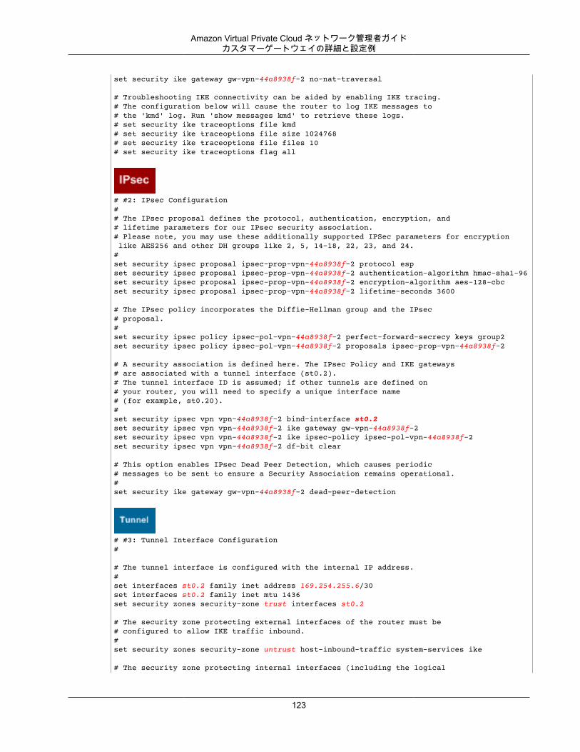
Amazon Virtual Private Cloud ネットワーク管理者ガイドカスタマーゲートウェイの詳細と設定例
set security ike gateway gw-vpn-44a8938f-2 no-nat-traversal
# Troubleshooting IKE connectivity can be aided by enabling IKE tracing.# The configuration below will cause the router to log IKE messages to# the 'kmd' log. Run 'show messages kmd' to retrieve these logs.# set security ike traceoptions file kmd# set security ike traceoptions file size 1024768# set security ike traceoptions file files 10# set security ike traceoptions flag all
# #2: IPsec Configuration## The IPsec proposal defines the protocol, authentication, encryption, and# lifetime parameters for our IPsec security association.# Please note, you may use these additionally supported IPSec parameters for encryption like AES256 and other DH groups like 2, 5, 14-18, 22, 23, and 24. #set security ipsec proposal ipsec-prop-vpn-44a8938f-2 protocol espset security ipsec proposal ipsec-prop-vpn-44a8938f-2 authentication-algorithm hmac-sha1-96set security ipsec proposal ipsec-prop-vpn-44a8938f-2 encryption-algorithm aes-128-cbcset security ipsec proposal ipsec-prop-vpn-44a8938f-2 lifetime-seconds 3600
# The IPsec policy incorporates the Diffie-Hellman group and the IPsec# proposal.#set security ipsec policy ipsec-pol-vpn-44a8938f-2 perfect-forward-secrecy keys group2set security ipsec policy ipsec-pol-vpn-44a8938f-2 proposals ipsec-prop-vpn-44a8938f-2
# A security association is defined here. The IPsec Policy and IKE gateways# are associated with a tunnel interface (st0.2).# The tunnel interface ID is assumed; if other tunnels are defined on# your router, you will need to specify a unique interface name # (for example, st0.20).#set security ipsec vpn vpn-44a8938f-2 bind-interface st0.2set security ipsec vpn vpn-44a8938f-2 ike gateway gw-vpn-44a8938f-2set security ipsec vpn vpn-44a8938f-2 ike ipsec-policy ipsec-pol-vpn-44a8938f-2set security ipsec vpn vpn-44a8938f-2 df-bit clear
# This option enables IPsec Dead Peer Detection, which causes periodic# messages to be sent to ensure a Security Association remains operational.#set security ike gateway gw-vpn-44a8938f-2 dead-peer-detection
# #3: Tunnel Interface Configuration#
# The tunnel interface is configured with the internal IP address.#set interfaces st0.2 family inet address 169.254.255.6/30set interfaces st0.2 family inet mtu 1436set security zones security-zone trust interfaces st0.2
# The security zone protecting external interfaces of the router must be # configured to allow IKE traffic inbound.#set security zones security-zone untrust host-inbound-traffic system-services ike
# The security zone protecting internal interfaces (including the logical
123
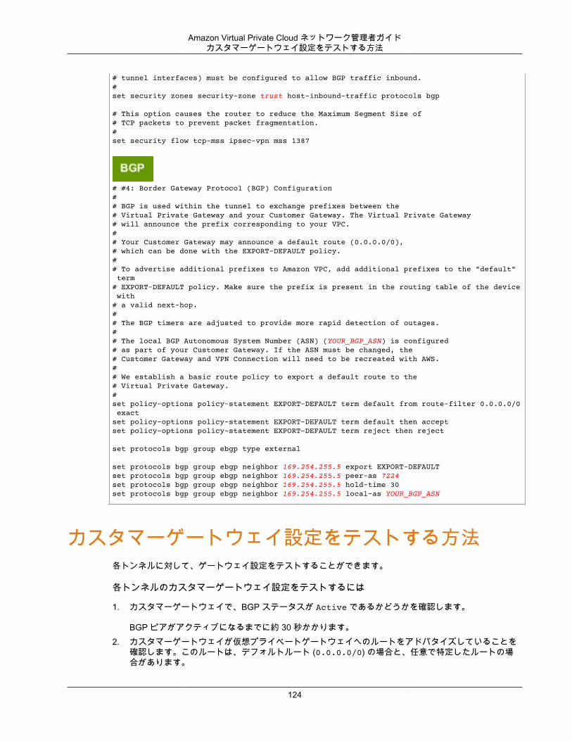
Amazon Virtual Private Cloud ネットワーク管理者ガイドカスタマーゲートウェイ設定をテストする方法
# tunnel interfaces) must be configured to allow BGP traffic inbound.#set security zones security-zone trust host-inbound-traffic protocols bgp
# This option causes the router to reduce the Maximum Segment Size of# TCP packets to prevent packet fragmentation.#set security flow tcp-mss ipsec-vpn mss 1387
# #4: Border Gateway Protocol (BGP) Configuration# # BGP is used within the tunnel to exchange prefixes between the# Virtual Private Gateway and your Customer Gateway. The Virtual Private Gateway # will announce the prefix corresponding to your VPC.# # Your Customer Gateway may announce a default route (0.0.0.0/0), # which can be done with the EXPORT-DEFAULT policy.## To advertise additional prefixes to Amazon VPC, add additional prefixes to the "default" term# EXPORT-DEFAULT policy. Make sure the prefix is present in the routing table of the device with # a valid next-hop.# # The BGP timers are adjusted to provide more rapid detection of outages. # # The local BGP Autonomous System Number (ASN) (YOUR_BGP_ASN) is configured# as part of your Customer Gateway. If the ASN must be changed, the # Customer Gateway and VPN Connection will need to be recreated with AWS.## We establish a basic route policy to export a default route to the# Virtual Private Gateway. #set policy-options policy-statement EXPORT-DEFAULT term default from route-filter 0.0.0.0/0 exact set policy-options policy-statement EXPORT-DEFAULT term default then accept set policy-options policy-statement EXPORT-DEFAULT term reject then reject
set protocols bgp group ebgp type external
set protocols bgp group ebgp neighbor 169.254.255.5 export EXPORT-DEFAULT set protocols bgp group ebgp neighbor 169.254.255.5 peer-as 7224set protocols bgp group ebgp neighbor 169.254.255.5 hold-time 30set protocols bgp group ebgp neighbor 169.254.255.5 local-as YOUR_BGP_ASN
カスタマーゲートウェイ設定をテストする方法各トンネルに対して、ゲートウェイ設定をテストすることができます。
各トンネルのカスタマーゲートウェイ設定をテストするには
1. カスタマーゲートウェイで、BGP ステータスが Active であるかどうかを確認します。
BGP ピアがアクティブになるまでに約 30 秒かかります。2. カスタマーゲートウェイが仮想プライベートゲートウェイへのルートをアドバタイズしていることを
確認します。このルートは、デフォルトルート (0.0.0.0/0) の場合と、任意で特定したルートの場合があります。
124

Amazon Virtual Private Cloud ネットワーク管理者ガイドカスタマーゲートウェイ設定をテストする方法
正しく設定されている場合、BGP ピアは、VPC 統合チームが VPC 用に指定したプレフィックス (たとえば、10.0.0.0/24) に対応する仮想プライベートゲートウェイから 1 つのルートを受け取ります。BGPピアが確立された場合は、プレフィックスを受け取り、プレフィックスをアドバタイズして、トンネルが正しく設定されます。両方のトンネルがこの状態であることを確認します。
次に、VPC でインスタンスを起動し、ホームネットワークからインスタンスへの ping を実行して、各トンネルの接続をテストする必要があります。開始する前に、以下を確認してください。
• ping リクエストに応答する AMI を使用します。Amazon Linux AMI のいずれかを使用することをお勧めします。
• インスタンスのセキュリティグループとネットワーク ACL を設定し、インバウンド ICMP トラフィックを有効にします。
• VPN 接続用のルーティングを設定していることを確認します。サブネットのルートテーブルに仮想プライベートゲートウェイへのルートが含まれている必要があります。詳細については、Amazon VPC ユーザーガイド の「ルートテーブルでルート伝達を有効にする」を参照してください。
各トンネルのエンドツーエンド接続をテストするには
1. VPC で Amazon Linux AMI の 1 つのインスタンスを起動します。Amazon EC2 コンソールからインスタンスを起動すると、起動ウィザードのリストに Amazon Linux AMI が表示されます。詳細については、「Amazon VPC 入門ガイド」を参照してください。
2. インスタンスが実行中になった後、そのプライベート IP アドレス (例えば 10.0.0.4) を取得します。 コンソールにインスタンスの詳細の一部としてアドレスが表示されます。
3. ホームネットワークのシステムで、インスタンスの IP アドレスに対して ping コマンドを実行します。ping を実行するコンピューターがカスタマーゲートウェイの背後にないことを確認します。正常なレスポンスは次のようになります。
ping 10.0.0.4
Pinging 10.0.0.4 with 32 bytes of data:
Reply from 10.0.0.4: bytes=32 time<1ms TTL=128Reply from 10.0.0.4: bytes=32 time<1ms TTL=128Reply from 10.0.0.4: bytes=32 time<1ms TTL=128
Ping statistics for 10.0.0.4:Packets: Sent = 3, Received = 3, Lost = 0 (0% loss),
Approximate round trip times in milliseconds:Minimum = 0ms, Maximum = 0ms, Average = 0ms
Note
カスタマーゲートウェイルーターからインスタンスへの ping を実行する場合は、ping メッセージの送信元がトンネル IP アドレスではなく内部 IP アドレスになるようにしてください。一部の AMI は、トンネル IP アドレスからの ping メッセージに応答しません。
4. (オプション) トンネル フェイルオーバーをテストするため、カスタマーゲートウェイのトンネルの 1つを一時的に無効化し、上記の手順を繰り返すことができます。VPN 接続の AWS 側のトンネルを無効化することはできません。
トンネルのテストを正常に実施できない場合は、「Juniper JunOS カスタマーゲートウェイの接続のトラブルシューティング (p. 188)」を参照してください。
125
Amazon Virtual Private Cloud ネットワーク管理者ガイド
例: Juniper ScreenOS デバイストピック
• カスタマーゲートウェイの概要 (p. 127)• カスタマーゲートウェイの詳細と設定例 (p. 128)• カスタマーゲートウェイ設定をテストする方法 (p. 133)
このセクションでは、Juniper ScreenOS ソフトウェアを実行している Juniper SSG または Netscreen シリーズのデバイスをカスタマーゲートウェイとして使用する場合に、統合チームから提供される設定情報の例について説明します。
2 つの図で設定例を紹介します。最初の図はカスタマーゲートウェイのレイアウトの概要を表し、2 番目の図はこの設定例の詳細を表しています。統合チームから受け取った実際の設定情報を使用して、カスタマーゲートウェイに適用する必要があります。
126

Amazon Virtual Private Cloud ネットワーク管理者ガイドカスタマーゲートウェイの概要
カスタマーゲートウェイの概要次の図は、カスタマーゲートウェイの全般的な説明を示しています。VPN 接続が 2 つの個別のトンネルで構成されている点に注意してください。冗長なトンネルを使用することで、デバイス障害の発生時にも可用性を継続的に維持できます。
127
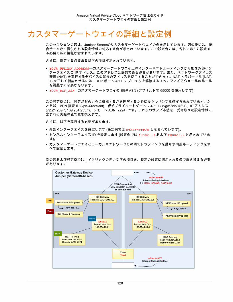
Amazon Virtual Private Cloud ネットワーク管理者ガイドカスタマーゲートウェイの詳細と設定例
カスタマーゲートウェイの詳細と設定例このセクションの図は、Juniper ScreenOS カスタマーゲートウェイの例を示しています。図の後には、統合チームから提供される設定情報の対応する例が示されています。この設定例には、各トンネルに設定する必要のある情報が含まれています。
さらに、指定する必要ある以下の項目が示されています。
• YOUR_UPLINK_ADDRESS—カスタマーゲートウェイ上のインターネットルーティングが可能な外部インターフェイスの IP アドレス。このアドレスは静的である必要があります。また、ネットワークアドレス変換 (NAT) を実行するデバイスの背後のアドレスを使用することができます。NAT トラバーサル (NAT-T) を正しく機能させるには、UDP ポート 4500 のブロックを解除するようにファイアウォールのルールを調整する必要があります。
• YOUR_BGP_ASN - カスタマーゲートウェイの BGP ASN (デフォルトで 65000 を使用します)
この設定例には、設定がどのように機能するかを理解するために役立つサンプル値が含まれています。たとえば、VPN 接続 ID (vpn-44a8938f)、仮想プライベートゲートウェイ ID (vgw-8db04f81)、IP アドレス(72.21.209.*, 169.254.255.*)、リモート ASN (7224) です。これらのサンプル値を、受け取った設定情報に含まれる実際の値で置き換えます。
さらに、以下を実行する必要があります。
• 外部インターフェイスを設定します (設定例では ethernet0/0 と示されています)。• トンネルインターフェイス ID を設定します (設定例では tunnel.1 および tunnel.2 と示されていま
す)。• カスタマーゲートウェイとローカルネットワークとの間でトラフィックを動かす内部ルーティングをす
べて設定します。
次の図および設定例では、イタリックの赤い文字の項目を、特定の設定に適用される値で置き換える必要があります。
128
Amazon Virtual Private Cloud ネットワーク管理者ガイドカスタマーゲートウェイの詳細と設定例
Warning
次の設定情報の例は、統合チームから提供されることが想定される内容です。この例の値の多くは、受け取る設定情報とは異なります。ここに示されるサンプル値ではなく、実際の値を使用する必要があります。そうしないと、実装が失敗します。
Important
以下の設定は、ScreenOS バージョン 6.2 以降に適しています。ScreenOS バージョン 6.1 に固有の設定をダウンロードできます。[Download Configuration] ダイアログボックスで、[JuniperNetworks, Inc.Vendor] リストから [] を選択、[SSG and ISG Series RoutersPlatform] リストから [] を選択、[ScreenOS 6.1Software] リストから [] を選択します。
# Amazon Web Services# Virtual Private Cloud## AWS utilizes unique identifiers to manipulate the configuration of a VPN # Connection. Each VPN Connection is assigned a VPN Connection Identifier# and is associated with two other identifiers, namely the Customer Gateway# Identifier and the Virtual Private Gateway Identifier.## Your VPN Connection ID : vpn-44a8938f# Your Virtual Private Gateway ID : vgw-8db04f81# Your Customer Gateway ID : cgw-b4dc3961## This configuration consists of two tunnels. Both tunnels must be configured# on your Customer Gateway.## This configuration was tested on a Juniper SSG-5 running ScreenOS 6.3R2.## --------------------------------------------------------------------------------# IPsec Tunnel #1# --------------------------------------------------------------------------------
# #1: Internet Key Exchange (IKE) Configuration## A proposal is established for the supported IKE encryption, authentication,# Diffie-Hellman, and lifetime parameters.## Please note, these sample configurations are for the minimum requirement of AES128, SHA1, and DH Group 2.# You will need to modify these sample configuration files to take advantage of AES256, SHA256, or other DH groups like 2, 14-18, 22, 23, and 24.# The address of the external interface for your customer gateway must be a static address. # Your customer gateway may reside behind a device performing network address translation (NAT).# To ensure that NAT traversal (NAT-T) can function, you must adjust your firewall rules to unblock UDP port 4500. If not behind NAT, we recommend disabling NAT-T.#set ike p1-proposal ike-prop-vpn-44a8938f-1 preshare group2 esp aes128 sha-1 second 28800
# The IKE gateway is defined to be the Virtual Private Gateway. The gateway configuration# associates a local interface, remote IP address, and IKE policy.## This example shows the outside of the tunnel as interface ethernet0/0. This# should be set to the interface that IP address YOUR_UPLINK_ADDRESS is# associated with.# This address is configured with the setup for your Customer Gateway.##If the address changes, the Customer Gateway and VPN Connection must be recreated.
129
Amazon Virtual Private Cloud ネットワーク管理者ガイドカスタマーゲートウェイの詳細と設定例
#
set ike gateway gw-vpn-44a8938f-1 address 72.21.209.225 id 72.21.209.225 main outgoing-interface ethernet0/0 preshare "plain-text-password1" proposal ike-prop-vpn-44a8938f-1
# Troubleshooting IKE connectivity can be aided by enabling IKE debugging.# To do so, run the following commands:# clear dbuf -- Clear debug buffer# debug ike all -- Enable IKE debugging# get dbuf stream -- View debug messages# undebug all -- Turn off debugging
# #2: IPsec Configuration## The IPsec (Phase 2) proposal defines the protocol, authentication,# encryption, and lifetime parameters for our IPsec security association.# Please note, you may use these additionally supported IPSec parameters for encryption like AES256 and other DH groups like 2, 5, 14-18, 22, 23, and 24.#
set ike p2-proposal ipsec-prop-vpn-44a8938f-1 group2 esp aes128 sha-1 second 3600set ike gateway gw-vpn-44a8938f-1 dpd-liveness interval 10set vpn IPSEC-vpn-44a8938f-1 gateway gw-vpn-44a8938f-1 replay tunnel proposal ipsec-prop-vpn-44a8938f-1
# #3: Tunnel Interface Configuration## The tunnel interface is configured with the internal IP address.## To establish connectivity between your internal network and the VPC, you# must have an interface facing your internal network in the "Trust" zone.#
set interface tunnel.1 zone Trustset interface tunnel.1 ip 169.254.255.2/30set interface tunnel.1 mtu 1436set vpn IPSEC-vpn-44a8938f-1 bind interface tunnel.1
# By default, the router will block asymmetric VPN traffic, which may occur# with this VPN Connection. This occurs, for example, when routing policies# cause traffic to sent from your router to VPC through one IPsec tunnel# while traffic returns from VPC through the other.## This command allows this traffic to be received by your device.
set zone Trust asymmetric-vpn
# This option causes the router to reduce the Maximum Segment Size of TCP# packets to prevent packet fragmentation.#
set flow vpn-tcp-mss 1387
# #4: Border Gateway Protocol (BGP) Configuration#
130
Amazon Virtual Private Cloud ネットワーク管理者ガイドカスタマーゲートウェイの詳細と設定例
# BGP is used within the tunnel to exchange prefixes between the Virtual Private Gateway# and your Customer Gateway. The Virtual Private Gateway will announce the prefix # corresponding to your VPC.## Your Customer Gateway may announce a default route (0.0.0.0/0). ## The BGP timers are adjusted to provide more rapid detection of outages.## The local BGP Autonomous System Number (ASN) (YOUR_BGP_ASN) is configured# as part of your Customer Gateway. If the ASN must be changed, the# Customer Gateway and VPN Connection will need to be recreated with AWS.#
set vrouter trust-vrset max-ecmp-routes 2set protocol bgp YOUR_BGP_ASNset hold-time 30set network 0.0.0.0/0# To advertise additional prefixes to Amazon VPC, copy the 'network' statement and # identify the prefix you wish to advertise (set ipv4 network X.X.X.X/X). Make sure the # prefix is present in the routing table of the device with a valid next-hop.
set enableset neighbor 169.254.255.1 remote-as 7224set neighbor 169.254.255.1 enableexitexitset interface tunnel.1 protocol bgp
# -------------------------------------------------------------------------# IPsec Tunnel #2# -------------------------------------------------------------------------
# #1: Internet Key Exchange (IKE) Configuration## A proposal is established for the supported IKE encryption, authentication,# Diffie-Hellman, and lifetime parameters.# Please note, these sample configurations are for the minimum requirement of AES128, SHA1, and DH Group 2.# You will need to modify these sample configuration files to take advantage of AES256, SHA256, or other DH groups like 2, 14-18, 22, 23, and 24.# The address of the external interface for your customer gateway must be a static address. # Your customer gateway may reside behind a device performing network address translation (NAT).# To ensure that NAT traversal (NAT-T) can function, you must adjust your firewall !rules to unblock UDP port 4500. If not behind NAT, we recommend disabling NAT-T.#
set ike p1-proposal ike-prop-vpn-44a8938f-2 preshare group2 esp aes128 sha-1 second 28800
# The IKE gateway is defined to be the Virtual Private Gateway. The gateway configuration# associates a local interface, remote IP address, and IKE policy.## This example shows the outside of the tunnel as interface ethernet0/0. This# should be set to the interface that IP address YOUR_UPLINK_ADDRESS is# associated with.## This address is configured with the setup for your Customer Gateway. If the# address changes, the Customer Gateway and VPN Connection must be recreated.#
131
Amazon Virtual Private Cloud ネットワーク管理者ガイドカスタマーゲートウェイの詳細と設定例
set ike gateway gw-vpn-44a8938f-2 address 72.21.209.193 id 72.21.209.193 main outgoing-interface ethernet0/0 preshare "plain-text-password2" proposal ike-prop-vpn-44a8938f-2
# Troubleshooting IKE connectivity can be aided by enabling IKE debugging.# To do so, run the following commands:# clear dbuf -- Clear debug buffer# debug ike all -- Enable IKE debugging# get dbuf stream -- View debug messages# undebug all -- Turn off debugging
# #2: IPsec Configuration## The IPsec (Phase 2) proposal defines the protocol, authentication,# encryption, and lifetime parameters for our IPsec security association.# Please note, you may use these additionally supported IPSec parameters for encryption like AES256 and other DH groups like 2, 5, 14-18, 22, 23, and 24.#
set ike p2-proposal ipsec-prop-vpn-44a8938f-2 group2 esp aes128 sha-1 second 3600set ike gateway gw-vpn-44a8938f-2 dpd-liveness interval 10set vpn IPSEC-vpn-44a8938f-2 gateway gw-vpn-44a8938f-2 replay tunnel proposal ipsec-prop-vpn-44a8938f-2
# #3: Tunnel Interface Configuration## The tunnel interface is configured with the internal IP address.## To establish connectivity between your internal network and the VPC, you# must have an interface facing your internal network in the "Trust" zone.
set interface tunnel.2 zone Trustset interface tunnel.2 ip 169.254.255.6/30set interface tunnel.2 mtu 1436set vpn IPSEC-vpn-44a8938f-2 bind interface tunnel.2
# By default, the router will block asymmetric VPN traffic, which may occur# with this VPN Connection. This occurs, for example, when routing policies# cause traffic to sent from your router to VPC through one IPsec tunnel# while traffic returns from VPC through the other.## This command allows this traffic to be received by your device.
set zone Trust asymmetric-vpn
# This option causes the router to reduce the Maximum Segment Size of TCP# packets to prevent packet fragmentation.
set flow vpn-tcp-mss 1387
# #4: Border Gateway Protocol (BGP) Configuration## BGP is used within the tunnel to exchange prefixes between the Virtual Private Gateway# and your Customer Gateway. The Virtual Private Gateway will announce the prefix # corresponding to your VPC.## Your Customer Gateway may announce a default route (0.0.0.0/0).
132
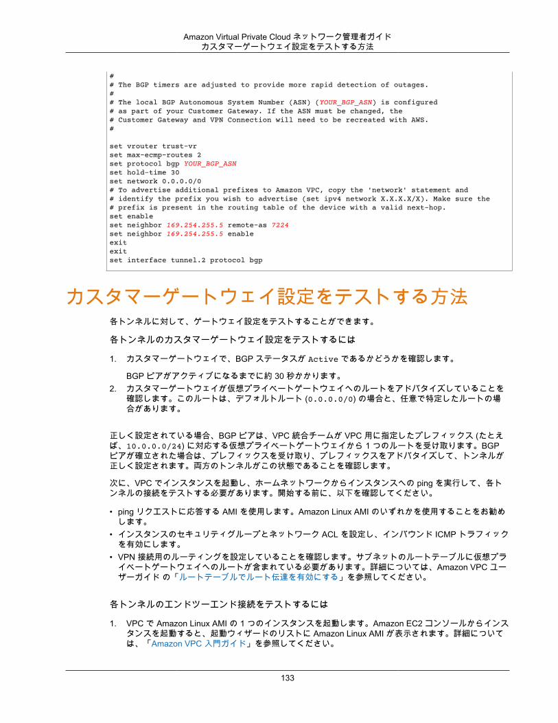
Amazon Virtual Private Cloud ネットワーク管理者ガイドカスタマーゲートウェイ設定をテストする方法
## The BGP timers are adjusted to provide more rapid detection of outages.## The local BGP Autonomous System Number (ASN) (YOUR_BGP_ASN) is configured# as part of your Customer Gateway. If the ASN must be changed, the# Customer Gateway and VPN Connection will need to be recreated with AWS.#
set vrouter trust-vrset max-ecmp-routes 2set protocol bgp YOUR_BGP_ASNset hold-time 30set network 0.0.0.0/0# To advertise additional prefixes to Amazon VPC, copy the 'network' statement and # identify the prefix you wish to advertise (set ipv4 network X.X.X.X/X). Make sure the # prefix is present in the routing table of the device with a valid next-hop. set enableset neighbor 169.254.255.5 remote-as 7224set neighbor 169.254.255.5 enableexitexitset interface tunnel.2 protocol bgp
カスタマーゲートウェイ設定をテストする方法各トンネルに対して、ゲートウェイ設定をテストすることができます。
各トンネルのカスタマーゲートウェイ設定をテストするには
1. カスタマーゲートウェイで、BGP ステータスが Active であるかどうかを確認します。
BGP ピアがアクティブになるまでに約 30 秒かかります。2. カスタマーゲートウェイが仮想プライベートゲートウェイへのルートをアドバタイズしていることを
確認します。このルートは、デフォルトルート (0.0.0.0/0) の場合と、任意で特定したルートの場合があります。
正しく設定されている場合、BGP ピアは、VPC 統合チームが VPC 用に指定したプレフィックス (たとえば、10.0.0.0/24) に対応する仮想プライベートゲートウェイから 1 つのルートを受け取ります。BGPピアが確立された場合は、プレフィックスを受け取り、プレフィックスをアドバタイズして、トンネルが正しく設定されます。両方のトンネルがこの状態であることを確認します。
次に、VPC でインスタンスを起動し、ホームネットワークからインスタンスへの ping を実行して、各トンネルの接続をテストする必要があります。開始する前に、以下を確認してください。
• ping リクエストに応答する AMI を使用します。Amazon Linux AMI のいずれかを使用することをお勧めします。
• インスタンスのセキュリティグループとネットワーク ACL を設定し、インバウンド ICMP トラフィックを有効にします。
• VPN 接続用のルーティングを設定していることを確認します。サブネットのルートテーブルに仮想プライベートゲートウェイへのルートが含まれている必要があります。詳細については、Amazon VPC ユーザーガイド の「ルートテーブルでルート伝達を有効にする」を参照してください。
各トンネルのエンドツーエンド接続をテストするには
1. VPC で Amazon Linux AMI の 1 つのインスタンスを起動します。Amazon EC2 コンソールからインスタンスを起動すると、起動ウィザードのリストに Amazon Linux AMI が表示されます。詳細については、「Amazon VPC 入門ガイド」を参照してください。
133
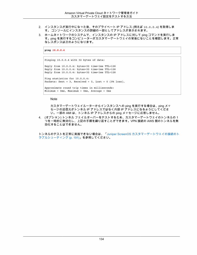
Amazon Virtual Private Cloud ネットワーク管理者ガイドカスタマーゲートウェイ設定をテストする方法
2. インスタンスが実行中になった後、そのプライベート IP アドレス (例えば 10.0.0.4) を取得します。 コンソールにインスタンスの詳細の一部としてアドレスが表示されます。
3. ホームネットワークのシステムで、インスタンスの IP アドレスに対して ping コマンドを実行します。ping を実行するコンピューターがカスタマーゲートウェイの背後にないことを確認します。正常なレスポンスは次のようになります。
ping 10.0.0.4
Pinging 10.0.0.4 with 32 bytes of data:
Reply from 10.0.0.4: bytes=32 time<1ms TTL=128Reply from 10.0.0.4: bytes=32 time<1ms TTL=128Reply from 10.0.0.4: bytes=32 time<1ms TTL=128
Ping statistics for 10.0.0.4:Packets: Sent = 3, Received = 3, Lost = 0 (0% loss),
Approximate round trip times in milliseconds:Minimum = 0ms, Maximum = 0ms, Average = 0ms
Note
カスタマーゲートウェイルーターからインスタンスへの ping を実行する場合は、ping メッセージの送信元がトンネル IP アドレスではなく内部 IP アドレスになるようにしてください。一部の AMI は、トンネル IP アドレスからの ping メッセージに応答しません。
4. (オプション) トンネル フェイルオーバーをテストするため、カスタマーゲートウェイのトンネルの 1つを一時的に無効化し、上記の手順を繰り返すことができます。VPN 接続の AWS 側のトンネルを無効化することはできません。
トンネルのテストを正常に実施できない場合は、「Juniper ScreenOS カスタマーゲートウェイの接続のトラブルシューティング (p. 191)」を参照してください。
134
Amazon Virtual Private Cloud ネットワーク管理者ガイドカスタマーゲートウェイの概要
例: ボーダーゲートウェイプロトコルを使用しない Netgate PfSense デバイス
トピック• カスタマーゲートウェイの概要 (p. 135)• 設定例 (p. 136)• カスタマーゲートウェイ設定をテストする方法 (p. 139)
このトピックでは、カスタマーゲートウェイが、OS 2.2.5 以降を搭載した Netgate pfSense ファイアウォールの場合のルーターの設定方法の例を取り上げます。
このトピックでは、Amazon VPC コンソールで、静的ルーティングの VPN 接続を設定済みであることを前提としています。詳細については、『Amazon VPC ユーザーガイド』の「VPC へのハードウェア仮想プライベートゲートウェイの追加」を参照してください。
カスタマーゲートウェイの概要次の図は、カスタマーゲートウェイの全般的な説明を示しています。VPN 接続が 2 つの個別のトンネル(Tunnel 1 と Tunnel 2) で構成されている点に注意してください。冗長なトンネルを使用することで、デバイス障害の発生時にも可用性を継続的に維持できます。
統合チームから受け取った実際の設定情報を使用して、カスタマーゲートウェイに適用する必要があります。
135
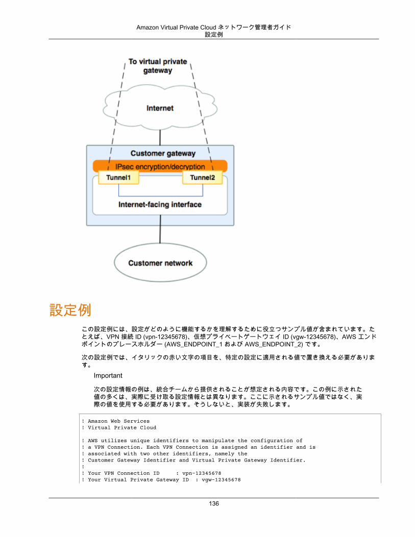
Amazon Virtual Private Cloud ネットワーク管理者ガイド設定例
設定例この設定例には、設定がどのように機能するかを理解するために役立つサンプル値が含まれています。たとえば、VPN 接続 ID (vpn-12345678)、仮想プライベートゲートウェイ ID (vgw-12345678)、AWS エンドポイントのプレースホルダー (AWS_ENDPOINT_1 および AWS_ENDPOINT_2) です。
次の設定例では、イタリックの赤い文字の項目を、特定の設定に適用される値で置き換える必要があります。
Important
次の設定情報の例は、統合チームから提供されることが想定される内容です。この例に示された値の多くは、実際に受け取る設定情報とは異なります。ここに示されるサンプル値ではなく、実際の値を使用する必要があります。そうしないと、実装が失敗します。
! Amazon Web Services! Virtual Private Cloud
! AWS utilizes unique identifiers to manipulate the configuration of ! a VPN Connection. Each VPN Connection is assigned an identifier and is ! associated with two other identifiers, namely the ! Customer Gateway Identifier and Virtual Private Gateway Identifier.!! Your VPN Connection ID : vpn-12345678! Your Virtual Private Gateway ID : vgw-12345678
136
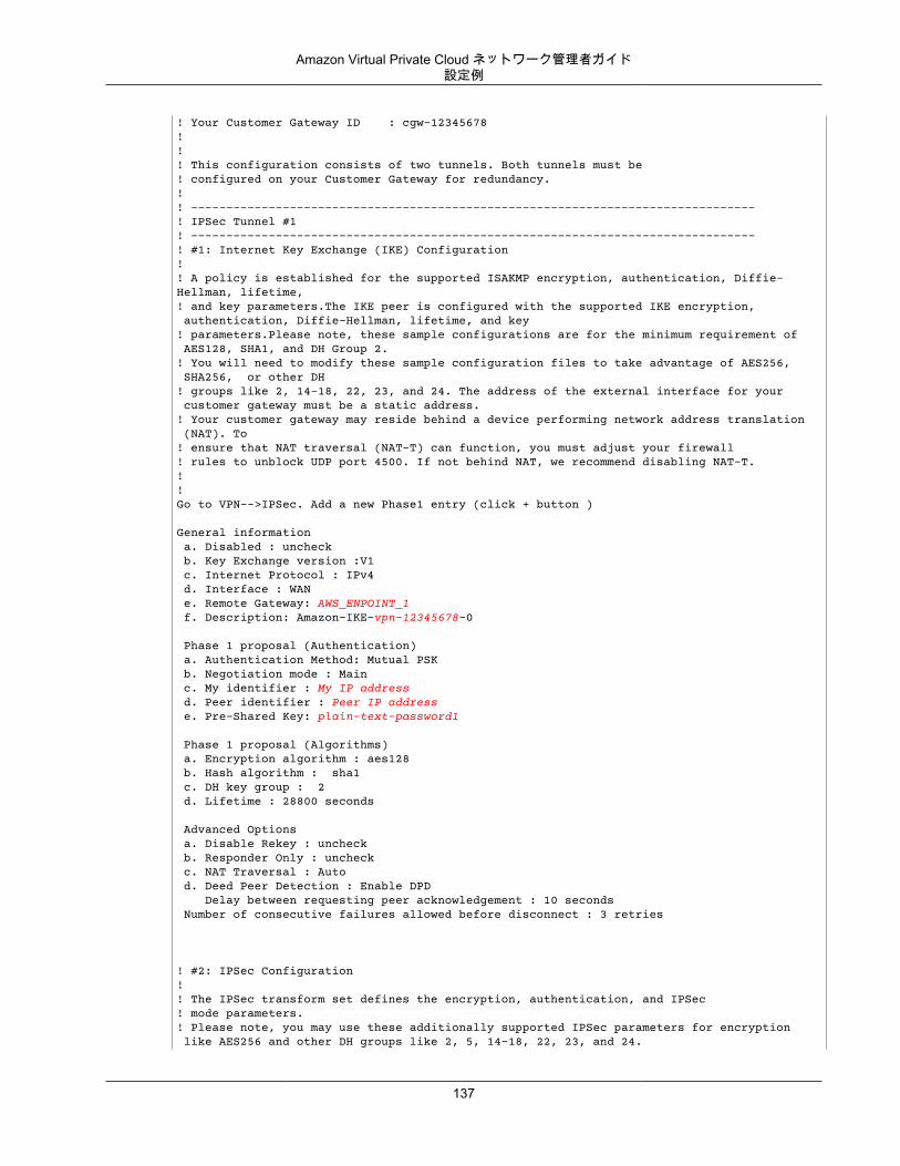
Amazon Virtual Private Cloud ネットワーク管理者ガイド設定例
! Your Customer Gateway ID : cgw-12345678!!! This configuration consists of two tunnels. Both tunnels must be ! configured on your Customer Gateway for redundancy.!! --------------------------------------------------------------------------------! IPSec Tunnel #1! --------------------------------------------------------------------------------! #1: Internet Key Exchange (IKE) Configuration!! A policy is established for the supported ISAKMP encryption, authentication, Diffie-Hellman, lifetime, ! and key parameters.The IKE peer is configured with the supported IKE encryption, authentication, Diffie-Hellman, lifetime, and key ! parameters.Please note, these sample configurations are for the minimum requirement of AES128, SHA1, and DH Group 2.! You will need to modify these sample configuration files to take advantage of AES256, SHA256, or other DH ! groups like 2, 14-18, 22, 23, and 24. The address of the external interface for your customer gateway must be a static address. ! Your customer gateway may reside behind a device performing network address translation (NAT). To ! ensure that NAT traversal (NAT-T) can function, you must adjust your firewall ! rules to unblock UDP port 4500. If not behind NAT, we recommend disabling NAT-T.!!Go to VPN-->IPSec. Add a new Phase1 entry (click + button )
General information a. Disabled : uncheck b. Key Exchange version :V1 c. Internet Protocol : IPv4 d. Interface : WAN e. Remote Gateway: AWS_ENPOINT_1 f. Description: Amazon-IKE-vpn-12345678-0 Phase 1 proposal (Authentication) a. Authentication Method: Mutual PSK b. Negotiation mode : Main c. My identifier : My IP address d. Peer identifier : Peer IP address e. Pre-Shared Key: plain-text-password1 Phase 1 proposal (Algorithms) a. Encryption algorithm : aes128 b. Hash algorithm : sha1 c. DH key group : 2 d. Lifetime : 28800 seconds Advanced Options a. Disable Rekey : uncheck b. Responder Only : uncheck c. NAT Traversal : Auto d. Deed Peer Detection : Enable DPD Delay between requesting peer acknowledgement : 10 seconds Number of consecutive failures allowed before disconnect : 3 retries
! #2: IPSec Configuration! ! The IPSec transform set defines the encryption, authentication, and IPSec! mode parameters.! Please note, you may use these additionally supported IPSec parameters for encryption like AES256 and other DH groups like 2, 5, 14-18, 22, 23, and 24.
137
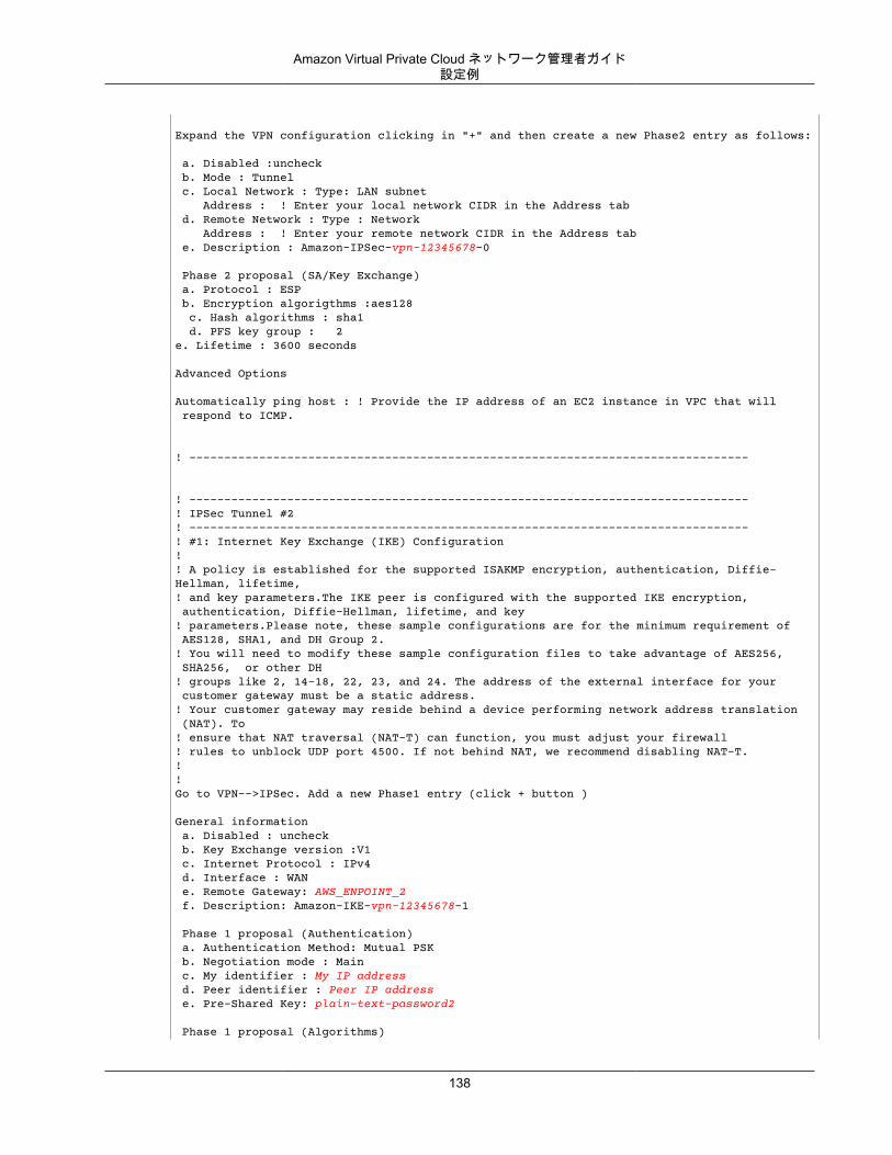
Amazon Virtual Private Cloud ネットワーク管理者ガイド設定例
Expand the VPN configuration clicking in "+" and then create a new Phase2 entry as follows:
a. Disabled :uncheck b. Mode : Tunnel c. Local Network : Type: LAN subnet Address : ! Enter your local network CIDR in the Address tab d. Remote Network : Type : Network Address : ! Enter your remote network CIDR in the Address tab e. Description : Amazon-IPSec-vpn-12345678-0 Phase 2 proposal (SA/Key Exchange) a. Protocol : ESP b. Encryption algorigthms :aes128 c. Hash algorithms : sha1 d. PFS key group : 2e. Lifetime : 3600 seconds
Advanced Options
Automatically ping host : ! Provide the IP address of an EC2 instance in VPC that will respond to ICMP.
! --------------------------------------------------------------------------------
! --------------------------------------------------------------------------------! IPSec Tunnel #2! --------------------------------------------------------------------------------! #1: Internet Key Exchange (IKE) Configuration!! A policy is established for the supported ISAKMP encryption, authentication, Diffie-Hellman, lifetime, ! and key parameters.The IKE peer is configured with the supported IKE encryption, authentication, Diffie-Hellman, lifetime, and key ! parameters.Please note, these sample configurations are for the minimum requirement of AES128, SHA1, and DH Group 2.! You will need to modify these sample configuration files to take advantage of AES256, SHA256, or other DH ! groups like 2, 14-18, 22, 23, and 24. The address of the external interface for your customer gateway must be a static address. ! Your customer gateway may reside behind a device performing network address translation (NAT). To ! ensure that NAT traversal (NAT-T) can function, you must adjust your firewall ! rules to unblock UDP port 4500. If not behind NAT, we recommend disabling NAT-T.!!Go to VPN-->IPSec. Add a new Phase1 entry (click + button )
General information a. Disabled : uncheck b. Key Exchange version :V1 c. Internet Protocol : IPv4 d. Interface : WAN e. Remote Gateway: AWS_ENPOINT_2 f. Description: Amazon-IKE-vpn-12345678-1 Phase 1 proposal (Authentication) a. Authentication Method: Mutual PSK b. Negotiation mode : Main c. My identifier : My IP address d. Peer identifier : Peer IP address e. Pre-Shared Key: plain-text-password2 Phase 1 proposal (Algorithms)
138
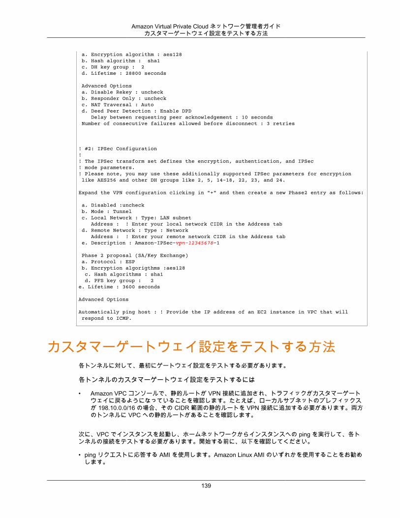
Amazon Virtual Private Cloud ネットワーク管理者ガイドカスタマーゲートウェイ設定をテストする方法
a. Encryption algorithm : aes128 b. Hash algorithm : sha1 c. DH key group : 2 d. Lifetime : 28800 seconds Advanced Options a. Disable Rekey : uncheck b. Responder Only : uncheck c. NAT Traversal : Auto d. Deed Peer Detection : Enable DPD Delay between requesting peer acknowledgement : 10 seconds Number of consecutive failures allowed before disconnect : 3 retries
! #2: IPSec Configuration! ! The IPSec transform set defines the encryption, authentication, and IPSec! mode parameters.! Please note, you may use these additionally supported IPSec parameters for encryption like AES256 and other DH groups like 2, 5, 14-18, 22, 23, and 24.
Expand the VPN configuration clicking in "+" and then create a new Phase2 entry as follows:
a. Disabled :uncheck b. Mode : Tunnel c. Local Network : Type: LAN subnet Address : ! Enter your local network CIDR in the Address tab d. Remote Network : Type : Network Address : ! Enter your remote network CIDR in the Address tab e. Description : Amazon-IPSec-vpn-12345678-1 Phase 2 proposal (SA/Key Exchange) a. Protocol : ESP b. Encryption algorigthms :aes128 c. Hash algorithms : sha1 d. PFS key group : 2e. Lifetime : 3600 seconds
Advanced Options
Automatically ping host : ! Provide the IP address of an EC2 instance in VPC that will respond to ICMP.
カスタマーゲートウェイ設定をテストする方法各トンネルに対して、最初にゲートウェイ設定をテストする必要があります。
各トンネルのカスタマーゲートウェイ設定をテストするには
• Amazon VPC コンソールで、静的ルートが VPN 接続に追加され、トラフィックがカスタマーゲートウェイに戻るようになっていることを確認します。たとえば、ローカルサブネットのプレフィックスが 198.10.0.0/16 の場合、その CIDR 範囲の静的ルートを VPN 接続に追加する必要があります。両方のトンネルに VPC への静的ルートがあることを確認します。
次に、VPC でインスタンスを起動し、ホームネットワークからインスタンスへの ping を実行して、各トンネルの接続をテストする必要があります。開始する前に、以下を確認してください。
• ping リクエストに応答する AMI を使用します。Amazon Linux AMI のいずれかを使用することをお勧めします。
139
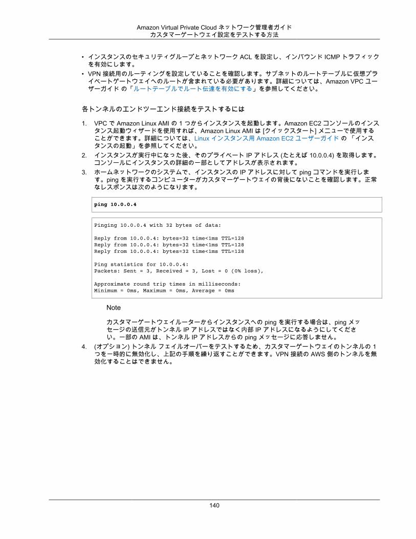
Amazon Virtual Private Cloud ネットワーク管理者ガイドカスタマーゲートウェイ設定をテストする方法
• インスタンスのセキュリティグループとネットワーク ACL を設定し、インバウンド ICMP トラフィックを有効にします。
• VPN 接続用のルーティングを設定していることを確認します。サブネットのルートテーブルに仮想プライベートゲートウェイへのルートが含まれている必要があります。詳細については、Amazon VPC ユーザーガイド の「ルートテーブルでルート伝達を有効にする」を参照してください。
各トンネルのエンドツーエンド接続をテストするには
1. VPC で Amazon Linux AMI の 1 つからインスタンスを起動します。Amazon EC2 コンソールのインスタンス起動ウィザードを使用すれば、Amazon Linux AMI は [クイックスタート] メニューで使用することができます。詳細については、Linux インスタンス用 Amazon EC2 ユーザーガイド の 「インスタンスの起動」を参照してください。
2. インスタンスが実行中になった後、そのプライベート IP アドレス (たとえば 10.0.0.4) を取得します。コンソールにインスタンスの詳細の一部としてアドレスが表示されます。
3. ホームネットワークのシステムで、インスタンスの IP アドレスに対して ping コマンドを実行します。ping を実行するコンピューターがカスタマーゲートウェイの背後にないことを確認します。正常なレスポンスは次のようになります。
ping 10.0.0.4
Pinging 10.0.0.4 with 32 bytes of data:
Reply from 10.0.0.4: bytes=32 time<1ms TTL=128Reply from 10.0.0.4: bytes=32 time<1ms TTL=128Reply from 10.0.0.4: bytes=32 time<1ms TTL=128
Ping statistics for 10.0.0.4:Packets: Sent = 3, Received = 3, Lost = 0 (0% loss),
Approximate round trip times in milliseconds:Minimum = 0ms, Maximum = 0ms, Average = 0ms
Note
カスタマーゲートウェイルーターからインスタンスへの ping を実行する場合は、ping メッセージの送信元がトンネル IP アドレスではなく内部 IP アドレスになるようにしてください。一部の AMI は、トンネル IP アドレスからの ping メッセージに応答しません。
4. (オプション) トンネル フェイルオーバーをテストするため、カスタマーゲートウェイのトンネルの 1つを一時的に無効化し、上記の手順を繰り返すことができます。VPN 接続の AWS 側のトンネルを無効化することはできません。
140
Amazon Virtual Private Cloud ネットワーク管理者ガイド
例: パロアルトネットワークスのデバイス
トピック• カスタマーゲートウェイの概要 (p. 142)• カスタマーゲートウェイの詳細と設定例 (p. 142)• カスタマーゲートウェイ設定をテストする方法 (p. 149)
次のトピックでは、お使いのカスタマーゲートウェイがパロアルトネットワークスの PANOS 4.1.2+ デバイスである場合、統合チームより提供される設定情報の例をご覧いただけます。
2 つの図で設定例を紹介します。最初の図はカスタマーゲートウェイのレイアウトの概要を表し、2 番目の図はこの設定例の詳細を表しています。統合チームから受け取った実際の設定情報を使用して、カスタマーゲートウェイに適用する必要があります。
141
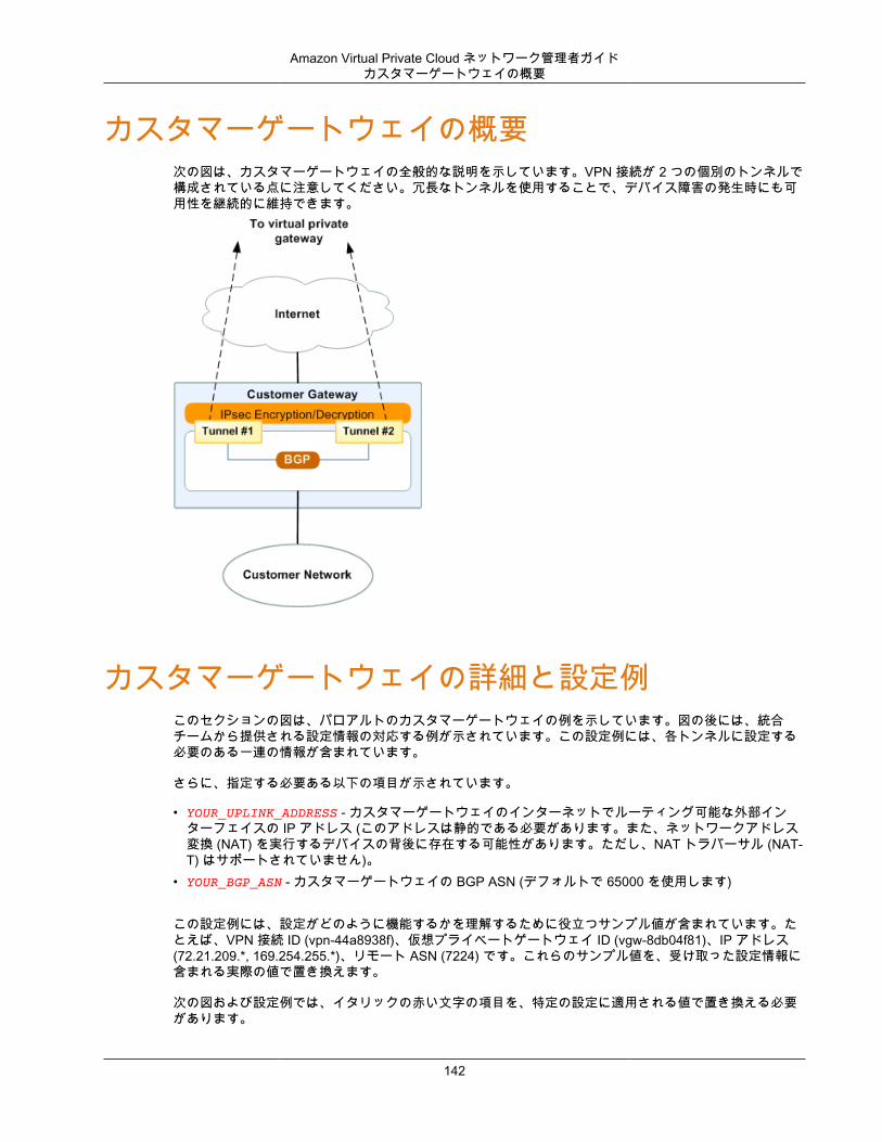
Amazon Virtual Private Cloud ネットワーク管理者ガイドカスタマーゲートウェイの概要
カスタマーゲートウェイの概要次の図は、カスタマーゲートウェイの全般的な説明を示しています。VPN 接続が 2 つの個別のトンネルで構成されている点に注意してください。冗長なトンネルを使用することで、デバイス障害の発生時にも可用性を継続的に維持できます。
カスタマーゲートウェイの詳細と設定例このセクションの図は、パロアルトのカスタマーゲートウェイの例を示しています。図の後には、統合チームから提供される設定情報の対応する例が示されています。この設定例には、各トンネルに設定する必要のある一連の情報が含まれています。
さらに、指定する必要ある以下の項目が示されています。
• YOUR_UPLINK_ADDRESS - カスタマーゲートウェイのインターネットでルーティング可能な外部インターフェイスの IP アドレス (このアドレスは静的である必要があります。また、ネットワークアドレス変換 (NAT) を実行するデバイスの背後に存在する可能性があります。ただし、NAT トラバーサル (NAT-T) はサポートされていません)。
• YOUR_BGP_ASN - カスタマーゲートウェイの BGP ASN (デフォルトで 65000 を使用します)
この設定例には、設定がどのように機能するかを理解するために役立つサンプル値が含まれています。たとえば、VPN 接続 ID (vpn-44a8938f)、仮想プライベートゲートウェイ ID (vgw-8db04f81)、IP アドレス(72.21.209.*, 169.254.255.*)、リモート ASN (7224) です。これらのサンプル値を、受け取った設定情報に含まれる実際の値で置き換えます。
次の図および設定例では、イタリックの赤い文字の項目を、特定の設定に適用される値で置き換える必要があります。
142
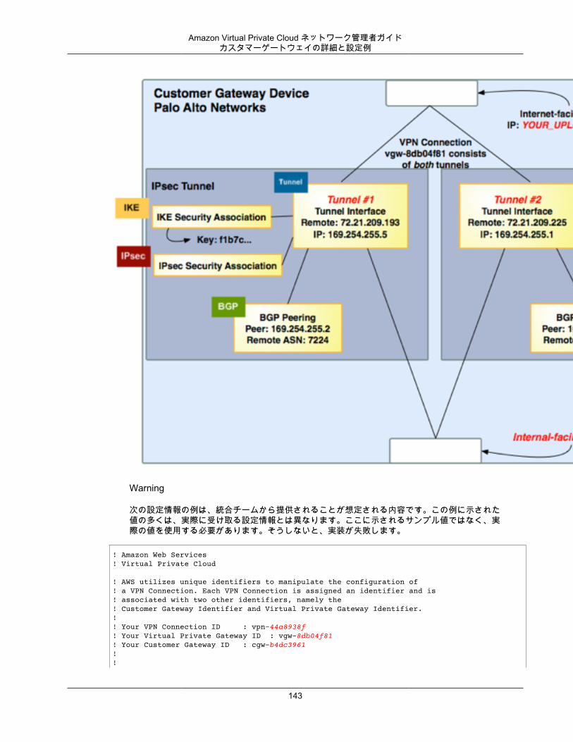
Amazon Virtual Private Cloud ネットワーク管理者ガイドカスタマーゲートウェイの詳細と設定例
Warning
次の設定情報の例は、統合チームから提供されることが想定される内容です。この例に示された値の多くは、実際に受け取る設定情報とは異なります。ここに示されるサンプル値ではなく、実際の値を使用する必要があります。そうしないと、実装が失敗します。
! Amazon Web Services! Virtual Private Cloud
! AWS utilizes unique identifiers to manipulate the configuration of ! a VPN Connection. Each VPN Connection is assigned an identifier and is ! associated with two other identifiers, namely the ! Customer Gateway Identifier and Virtual Private Gateway Identifier.!! Your VPN Connection ID : vpn-44a8938f! Your Virtual Private Gateway ID : vgw-8db04f81! Your Customer Gateway ID : cgw-b4dc3961!!
143
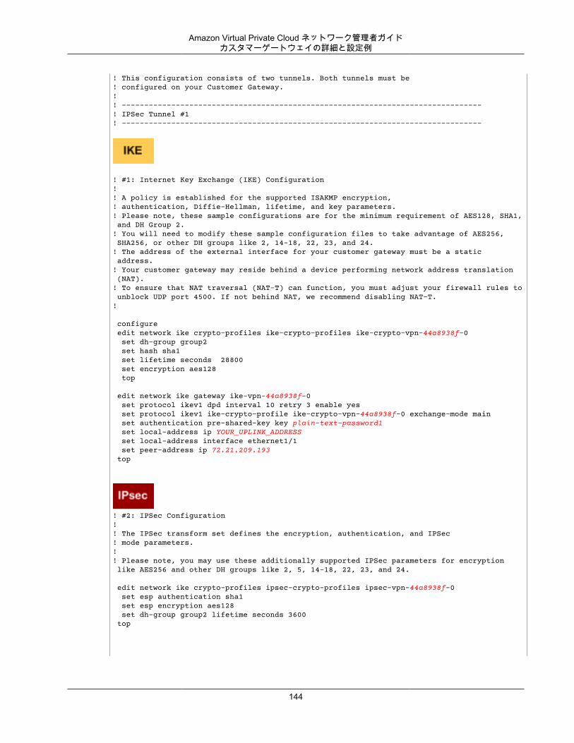
Amazon Virtual Private Cloud ネットワーク管理者ガイドカスタマーゲートウェイの詳細と設定例
! This configuration consists of two tunnels. Both tunnels must be ! configured on your Customer Gateway.!! --------------------------------------------------------------------------------! IPSec Tunnel #1! --------------------------------------------------------------------------------
! #1: Internet Key Exchange (IKE) Configuration!! A policy is established for the supported ISAKMP encryption, ! authentication, Diffie-Hellman, lifetime, and key parameters.! Please note, these sample configurations are for the minimum requirement of AES128, SHA1, and DH Group 2.! You will need to modify these sample configuration files to take advantage of AES256, SHA256, or other DH groups like 2, 14-18, 22, 23, and 24.! The address of the external interface for your customer gateway must be a static address. ! Your customer gateway may reside behind a device performing network address translation (NAT).! To ensure that NAT traversal (NAT-T) can function, you must adjust your firewall rules to unblock UDP port 4500. If not behind NAT, we recommend disabling NAT-T.!
configure edit network ike crypto-profiles ike-crypto-profiles ike-crypto-vpn-44a8938f-0 set dh-group group2 set hash sha1 set lifetime seconds 28800 set encryption aes128 top
edit network ike gateway ike-vpn-44a8938f-0 set protocol ikev1 dpd interval 10 retry 3 enable yes set protocol ikev1 ike-crypto-profile ike-crypto-vpn-44a8938f-0 exchange-mode main set authentication pre-shared-key key plain-text-password1 set local-address ip YOUR_UPLINK_ADDRESS set local-address interface ethernet1/1 set peer-address ip 72.21.209.193 top
! #2: IPSec Configuration! ! The IPSec transform set defines the encryption, authentication, and IPSec! mode parameters.!! Please note, you may use these additionally supported IPSec parameters for encryption like AES256 and other DH groups like 2, 5, 14-18, 22, 23, and 24.
edit network ike crypto-profiles ipsec-crypto-profiles ipsec-vpn-44a8938f-0 set esp authentication sha1 set esp encryption aes128 set dh-group group2 lifetime seconds 3600 top
144
Amazon Virtual Private Cloud ネットワーク管理者ガイドカスタマーゲートウェイの詳細と設定例
! --------------------------------------------------------------------------------! #3: Tunnel Interface Configuration! ! A tunnel interface is configured to be the logical interface associated ! with the tunnel. All traffic routed to the tunnel interface will be ! encrypted and transmitted to the VPC. Similarly, traffic from the VPC! will be logically received on this interface.!! Association with the IPSec security association is done through the ! "tunnel protection" command.!! The address of the interface is configured with the setup for your ! Customer Gateway. If the address changes, the Customer Gateway and VPN ! Connection must be recreated with Amazon VPC.!
edit network interface tunnel set ip 169.254.255.5/30 set units tunnel.1 set mtu 1427 top
edit network tunnel ipsec ipsec-tunnel-1 set auto-key ike-gateway ike-vpn-44a8938f-0 set auto-key ipsec-crypto-profile ipsec-vpn-44a8938f-0 set tunnel-interface tunnel.1 set anti-replay yes
! --------------------------------------------------------------------------------
! #4: Border Gateway Protocol (BGP) Configuration! ! BGP is used within the tunnel to exchange prefixes between the! Virtual Private Gateway and your Customer Gateway. The Virtual Private Gateway ! will announce the prefix corresponding to your VPC.! !!! The local BGP Autonomous System Number (ASN) (YOUR_BGP_ASN)! is configured as part of your Customer Gateway. If the ASN must ! be changed, the Customer Gateway and VPN Connection will need to be recreated with AWS.!
edit network virtual-router default protocol bgp set enable yes set router-id YOUR_UPLINK_ADDRESS set local-as YOUR_BGP_ASN edit peer-group AmazonBGP edit peer amazon-tunnel-44a8938f-0 set connection-options keep-alive-interval 10 set connection-options hold-time 30 set enable yes set local-address ip 169.254.255.5/30
145
Amazon Virtual Private Cloud ネットワーク管理者ガイドカスタマーゲートウェイの詳細と設定例
set local-address interface tunnel.1 set peer-as 7224 set peer-address ip 169.254.255.2 top
! Your Customer Gateway may announce a default route (0.0.0.0/0) to us.
edit network virtual-router default protocol bgp policy set export rules vr-export action allow set match address-prefix 0.0.0.0/0 exact yes set used-by AmazonBGP enable yes top
! To advertise additional prefixes to Amazon VPC, add these prefixes to the 'address-prefix'! statement and identify the prefix you wish to advertise. Make sure the prefix is present ! in the routing table of the device with a valid next-hop. If you want to advertise ! 192.168.0.0/16 to Amazon, this can be done using the following.
edit network virtual-router default protocol bgp policy set export rules vr-export action allow set match address-prefix 192.168.0.0/16 exact yes set used-by AmazonBGP enable yes top
!
! --------------------------------------------------------------------------------! IPSec Tunnel #2! --------------------------------------------------------------------------------! #1: Internet Key Exchange (IKE) Configuration!! A policy is established for the supported ISAKMP encryption, ! authentication, Diffie-Hellman, lifetime, and key parameters.! Please note, these sample configurations are for the minimum requirement of AES128, SHA1, and DH Group 2.! You will need to modify these sample configuration files to take advantage of AES256, SHA256, or other DH groups like 2, 14-18, 22, 23, and 24.! The address of the external interface for your customer gateway must be a static address. ! Your customer gateway may reside behind a device performing network address translation (NAT).! To ensure that NAT traversal (NAT-T) can function, you must adjust your firewall !rules to unblock UDP port 4500. If not behind NAT, we recommend disabling NAT-T.!
configure edit network ike crypto-profiles ike-crypto-profiles ike-crypto-vpn-44a8938f-1 set dh-group group2 set hash sha1 set lifetime seconds 28800 set encryption aes128 top
edit network ike gateway ike-vpn-44a8938f-1
146
Amazon Virtual Private Cloud ネットワーク管理者ガイドカスタマーゲートウェイの詳細と設定例
set protocol ikev1 dpd interval 10 retry 3 enable yes set protocol ikev1 ike-crypto-profile ike-crypto-vpn-35a6445c-1 exchange-mode main set authentication pre-shared-key key plain-text-password2 set local-address ip YOUR_UPLINK_ADDRESS set local-address interface ethernet1/1 set peer-address ip 72.21.209.225 top
! #2: IPSec Configuration! ! The IPSec transform set defines the encryption, authentication, and IPSec! mode parameters.!! Please note, you may use these additionally supported IPSec parameters for encryption like AES256 and other DH groups like 2, 5, 14-18, 22, 23, and 24.
edit network ike crypto-profiles ipsec-crypto-profiles ipsec-vpn-44a8938f-1 set esp authentication sha1 set esp encryption aes128 set dh-group group2 lifetime seconds 3600 top
! --------------------------------------------------------------------------------! #3: Tunnel Interface Configuration! ! A tunnel interface is configured to be the logical interface associated ! with the tunnel. All traffic routed to the tunnel interface will be ! encrypted and transmitted to the VPC. Similarly, traffic from the VPC! will be logically received on this interface.!! Association with the IPSec security association is done through the ! "tunnel protection" command.!! The address of the interface is configured with the setup for your ! Customer Gateway. If the address changes, the Customer Gateway and VPN ! Connection must be recreated with Amazon VPC.!
edit network interface tunnel set ip 169.254.255.1/30 set units tunnel.2 set mtu 1427 top
edit network tunnel ipsec ipsec-tunnel-2 set auto-key ike-gateway ike-vpn-44a8938f-1 set auto-key ipsec-crypto-profile ipsec-vpn-44a8938f-1 set tunnel-interface tunnel.2 set anti-replay yes
147
Amazon Virtual Private Cloud ネットワーク管理者ガイドカスタマーゲートウェイの詳細と設定例
! #4: Border Gateway Protocol (BGP) Configuration! ! BGP is used within the tunnel to exchange prefixes between the! Virtual Private Gateway and your Customer Gateway. The Virtual Private Gateway ! will announce the prefix corresponding to your VPC.! !!! The local BGP Autonomous System Number (ASN) (YOUR_BGP_ASN)! is configured as part of your Customer Gateway. If the ASN must ! be changed, the Customer Gateway and VPN Connection will need to be recreated with AWS.!
edit network virtual-router default protocol bgp set enable yes set router-id YOUR_UPLINK_ADDRESS set local-as YOUR_BGP_ASN edit peer-group AmazonBGP edit peer amazon-tunnel-44a8938f-1 set connection-options keep-alive-interval 10 set connection-options hold-time 30 set enable yes set local-address ip 169.254.255.1/30 set local-address interface tunnel.2 set peer-as 7224 set peer-address ip 169.254.255.6.113 top
! Your Customer Gateway may announce a default route (0.0.0.0/0) to us.
edit network virtual-router default protocol bgp policy set export rules vr-export action allow set match address-prefix 0.0.0.0/0 exact yes set used-by AmazonBGP enable yes top
! To advertise additional prefixes to Amazon VPC, add these prefixes to the 'address-prefix'! statement and identify the prefix you wish to advertise. Make sure the prefix is present ! in the routing table of the device with a valid next-hop. If you want to advertise ! 192.168.0.0/16 to Amazon, this can be done using the following.
edit network virtual-router default protocol bgp policy set export rules vr-export action allow set match address-prefix 192.168.0.0/16 exact yes set used-by AmazonBGP enable yes top
!
148

Amazon Virtual Private Cloud ネットワーク管理者ガイドカスタマーゲートウェイ設定をテストする方法
カスタマーゲートウェイ設定をテストする方法各トンネルに対して、ゲートウェイ設定をテストすることができます。
各トンネルのカスタマーゲートウェイ設定をテストするには
1. カスタマーゲートウェイで、BGP ステータスが Active であるかどうかを確認します。
BGP ピアがアクティブになるまでに約 30 秒かかります。2. カスタマーゲートウェイが仮想プライベートゲートウェイへのルートをアドバタイズしていることを
確認します。このルートは、デフォルトルート (0.0.0.0/0) の場合と、任意で特定したルートの場合があります。
正しく設定されている場合、BGP ピアは、VPC 統合チームが VPC 用に指定したプレフィックス (たとえば、10.0.0.0/24) に対応する仮想プライベートゲートウェイから 1 つのルートを受け取ります。BGPピアが確立された場合は、プレフィックスを受け取り、プレフィックスをアドバタイズして、トンネルが正しく設定されます。両方のトンネルがこの状態であることを確認します。
次に、VPC でインスタンスを起動し、ホームネットワークからインスタンスへの ping を実行して、各トンネルの接続をテストする必要があります。開始する前に、以下を確認してください。
• ping リクエストに応答する AMI を使用します。Amazon Linux AMI のいずれかを使用することをお勧めします。
• インスタンスのセキュリティグループとネットワーク ACL を設定し、インバウンド ICMP トラフィックを有効にします。
• VPN 接続用のルーティングを設定していることを確認します。サブネットのルートテーブルに仮想プライベートゲートウェイへのルートが含まれている必要があります。詳細については、Amazon VPC ユーザーガイド の「ルートテーブルでルート伝達を有効にする」を参照してください。
各トンネルのエンドツーエンド接続をテストするには
1. VPC で Amazon Linux AMI の 1 つのインスタンスを起動します。Amazon EC2 コンソールからインスタンスを起動すると、起動ウィザードのリストに Amazon Linux AMI が表示されます。詳細については、「Amazon VPC 入門ガイド」を参照してください。
2. インスタンスが実行中になった後、そのプライベート IP アドレス (例えば 10.0.0.4) を取得します。 コンソールにインスタンスの詳細の一部としてアドレスが表示されます。
3. ホームネットワークのシステムで、インスタンスの IP アドレスに対して ping コマンドを実行します。ping を実行するコンピューターがカスタマーゲートウェイの背後にないことを確認します。正常なレスポンスは次のようになります。
ping 10.0.0.4
Pinging 10.0.0.4 with 32 bytes of data:
Reply from 10.0.0.4: bytes=32 time<1ms TTL=128Reply from 10.0.0.4: bytes=32 time<1ms TTL=128Reply from 10.0.0.4: bytes=32 time<1ms TTL=128
Ping statistics for 10.0.0.4:Packets: Sent = 3, Received = 3, Lost = 0 (0% loss),
Approximate round trip times in milliseconds:Minimum = 0ms, Maximum = 0ms, Average = 0ms
149

Amazon Virtual Private Cloud ネットワーク管理者ガイドカスタマーゲートウェイ設定をテストする方法
Note
カスタマーゲートウェイルーターからインスタンスへの ping を実行する場合は、ping メッセージの送信元がトンネル IP アドレスではなく内部 IP アドレスになるようにしてください。一部の AMI は、トンネル IP アドレスからの ping メッセージに応答しません。
4. (オプション) トンネル フェイルオーバーをテストするため、カスタマーゲートウェイのトンネルの 1つを一時的に無効化し、上記の手順を繰り返すことができます。VPN 接続の AWS 側のトンネルを無効化することはできません。
150
Amazon Virtual Private Cloud ネットワーク管理者ガイド
例: Yamaha 製デバイストピック
• カスタマーゲートウェイの概要 (p. 152)• カスタマーゲートウェイの詳細と設定例 (p. 152)• カスタマーゲートウェイ設定をテストする方法 (p. 158)
このセクションでは、カスタマーゲートウェイがRT107e、RTX1200、RTX1210、RTX1500、RTX3000、SRT100 のいずれかの Yamaha 製ルーターである場合に、統合チームから提供される設定情報の例について説明します。
2 つの図で設定例を紹介します。最初の図はカスタマーゲートウェイのレイアウトの概要を表し、2 番目の図はこの設定例の詳細を表しています。統合チームから受け取った実際の設定情報を使用して、カスタマーゲートウェイに適用する必要があります。
151
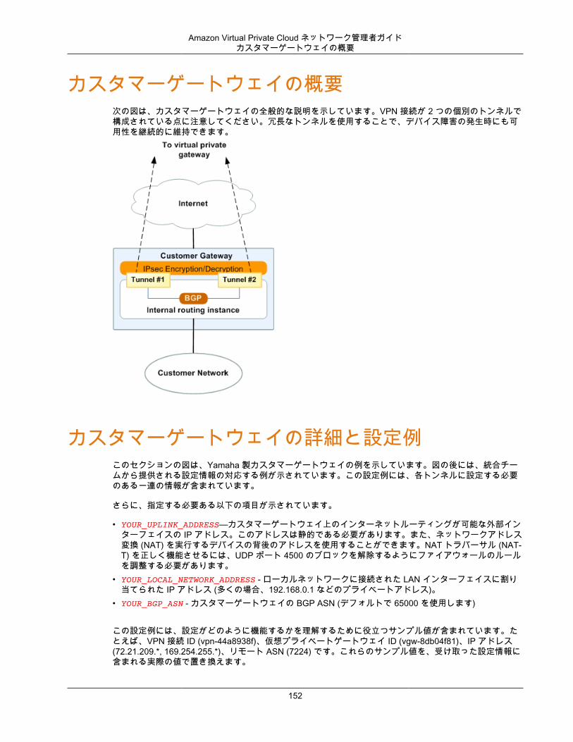
Amazon Virtual Private Cloud ネットワーク管理者ガイドカスタマーゲートウェイの概要
カスタマーゲートウェイの概要次の図は、カスタマーゲートウェイの全般的な説明を示しています。VPN 接続が 2 つの個別のトンネルで構成されている点に注意してください。冗長なトンネルを使用することで、デバイス障害の発生時にも可用性を継続的に維持できます。
カスタマーゲートウェイの詳細と設定例このセクションの図は、Yamaha 製カスタマーゲートウェイの例を示しています。図の後には、統合チームから提供される設定情報の対応する例が示されています。この設定例には、各トンネルに設定する必要のある一連の情報が含まれています。
さらに、指定する必要ある以下の項目が示されています。
• YOUR_UPLINK_ADDRESS—カスタマーゲートウェイ上のインターネットルーティングが可能な外部インターフェイスの IP アドレス。このアドレスは静的である必要があります。また、ネットワークアドレス変換 (NAT) を実行するデバイスの背後のアドレスを使用することができます。NAT トラバーサル (NAT-T) を正しく機能させるには、UDP ポート 4500 のブロックを解除するようにファイアウォールのルールを調整する必要があります。
• YOUR_LOCAL_NETWORK_ADDRESS - ローカルネットワークに接続された LAN インターフェイスに割り当てられた IP アドレス (多くの場合、192.168.0.1 などのプライベートアドレス)。
• YOUR_BGP_ASN - カスタマーゲートウェイの BGP ASN (デフォルトで 65000 を使用します)
この設定例には、設定がどのように機能するかを理解するために役立つサンプル値が含まれています。たとえば、VPN 接続 ID (vpn-44a8938f)、仮想プライベートゲートウェイ ID (vgw-8db04f81)、IP アドレス(72.21.209.*, 169.254.255.*)、リモート ASN (7224) です。これらのサンプル値を、受け取った設定情報に含まれる実際の値で置き換えます。
152
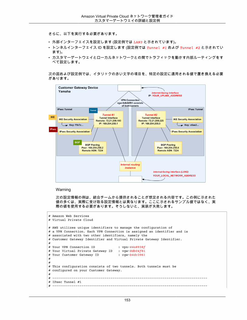
Amazon Virtual Private Cloud ネットワーク管理者ガイドカスタマーゲートウェイの詳細と設定例
さらに、以下を実行する必要があります。
• 外部インターフェイスを設定します (設定例では LAN3 と示されています)。• トンネルインターフェイス ID を設定します (設定例では Tunnel #1 および Tunnel #2 と示されてい
ます)。• カスタマーゲートウェイとローカルネットワークとの間でトラフィックを動かす内部ルーティングをす
べて設定します。
次の図および設定例では、イタリックの赤い文字の項目を、特定の設定に適用される値で置き換える必要があります。
Warning
次の設定情報の例は、統合チームから提供されることが想定される内容です。この例に示された値の多くは、実際に受け取る設定情報とは異なります。ここに示されるサンプル値ではなく、実際の値を使用する必要があります。そうしないと、実装が失敗します。
# Amazon Web Services # Virtual Private Cloud # AWS utilizes unique identifiers to manage the configuration of # a VPN Connection. Each VPN Connection is assigned an identifier and is # associated with two other identifiers, namely the # Customer Gateway Identifier and Virtual Private Gateway Identifier. # # Your VPN Connection ID : vpn-44a8938f # Your Virtual Private Gateway ID : vgw-8db04f81 # Your Customer Gateway ID : cgw-b4dc3961 # # # This configuration consists of two tunnels. Both tunnels must be # configured on your Customer Gateway. # # -------------------------------------------------------------------------------- # IPsec Tunnel #1 # --------------------------------------------------------------------------------
153
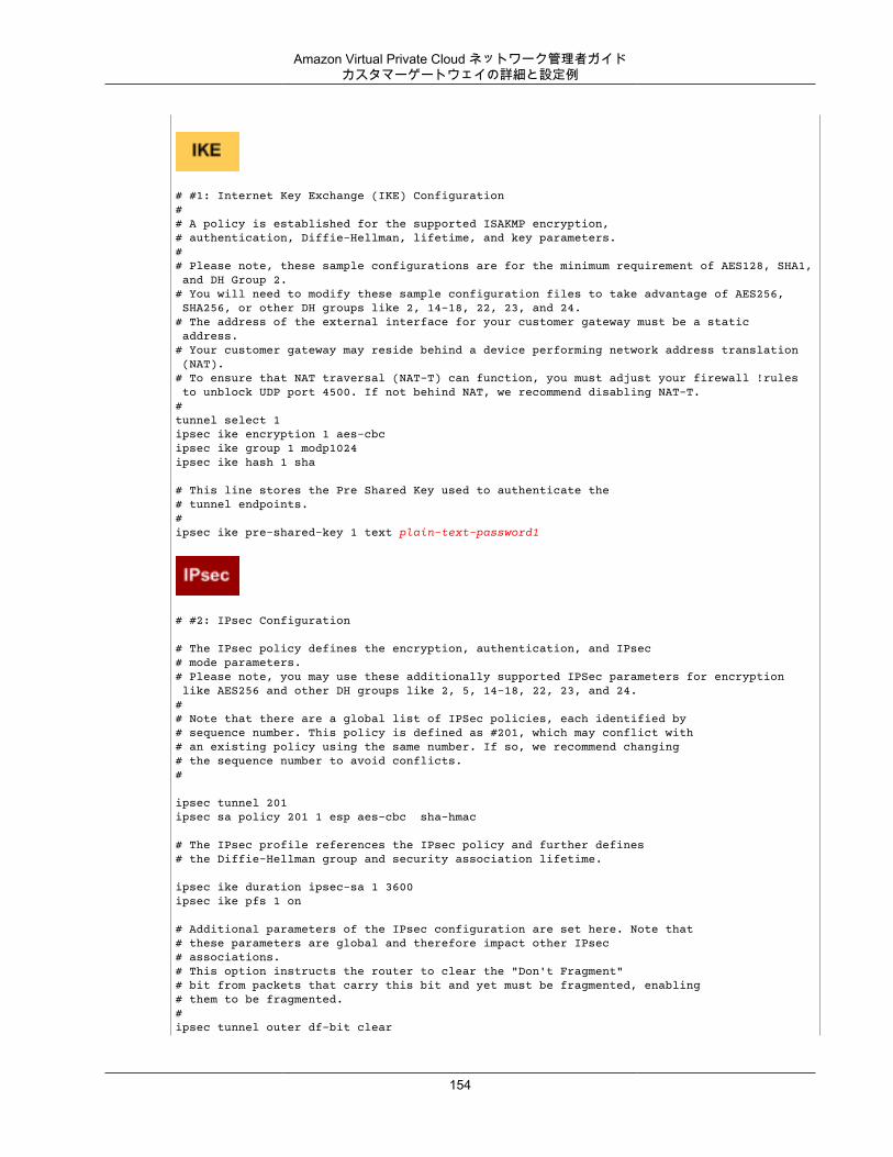
Amazon Virtual Private Cloud ネットワーク管理者ガイドカスタマーゲートウェイの詳細と設定例
# #1: Internet Key Exchange (IKE) Configuration # # A policy is established for the supported ISAKMP encryption, # authentication, Diffie-Hellman, lifetime, and key parameters. # # Please note, these sample configurations are for the minimum requirement of AES128, SHA1, and DH Group 2.# You will need to modify these sample configuration files to take advantage of AES256, SHA256, or other DH groups like 2, 14-18, 22, 23, and 24. # The address of the external interface for your customer gateway must be a static address. # Your customer gateway may reside behind a device performing network address translation (NAT).# To ensure that NAT traversal (NAT-T) can function, you must adjust your firewall !rules to unblock UDP port 4500. If not behind NAT, we recommend disabling NAT-T.#tunnel select 1 ipsec ike encryption 1 aes-cbc ipsec ike group 1 modp1024 ipsec ike hash 1 sha # This line stores the Pre Shared Key used to authenticate the # tunnel endpoints.# ipsec ike pre-shared-key 1 text plain-text-password1
# #2: IPsec Configuration # The IPsec policy defines the encryption, authentication, and IPsec # mode parameters. # Please note, you may use these additionally supported IPSec parameters for encryption like AES256 and other DH groups like 2, 5, 14-18, 22, 23, and 24.## Note that there are a global list of IPSec policies, each identified by # sequence number. This policy is defined as #201, which may conflict with# an existing policy using the same number. If so, we recommend changing # the sequence number to avoid conflicts.# ipsec tunnel 201 ipsec sa policy 201 1 esp aes-cbc sha-hmac # The IPsec profile references the IPsec policy and further defines # the Diffie-Hellman group and security association lifetime. ipsec ike duration ipsec-sa 1 3600 ipsec ike pfs 1 on # Additional parameters of the IPsec configuration are set here. Note that # these parameters are global and therefore impact other IPsec # associations. # This option instructs the router to clear the "Don't Fragment" # bit from packets that carry this bit and yet must be fragmented, enabling # them to be fragmented. # ipsec tunnel outer df-bit clear
154
Amazon Virtual Private Cloud ネットワーク管理者ガイドカスタマーゲートウェイの詳細と設定例
# This option enables IPsec Dead Peer Detection, which causes periodic # messages to be sent to ensure a Security Association remains operational. ipsec ike keepalive use 1 on dpd 10 3
# -------------------------------------------------------------------------------- # #3: Tunnel Interface Configuration # # A tunnel interface is configured to be the logical interface associated # with the tunnel. All traffic routed to the tunnel interface will be # encrypted and transmitted to the VPC. Similarly, traffic from the VPC # will be logically received on this interface. # # # The address of the interface is configured with the setup for your # Customer Gateway. If the address changes, the Customer Gateway and VPN # Connection must be recreated with Amazon VPC. # ipsec ike local address 1 YOUR_LOCAL_NETWORK_ADDRESS ipsec ike remote address 1 72.21.209.225 ip tunnel address 169.254.255.2/30 ip tunnel remote address 169.254.255.1 # This option causes the router to reduce the Maximum Segment Size of # TCP packets to prevent packet fragmentation ip tunnel tcp mss limit 1387tunnel enable 1tunnel select noneipsec auto refresh on
# -------------------------------------------------------------------------------- # #4: Border Gateway Protocol (BGP) Configuration # # BGP is used within the tunnel to exchange prefixes between the # Virtual Private Gateway and your Customer Gateway. The Virtual Private Gateway # will announce the prefix corresponding to your VPC. # # Your Customer Gateway may announce a default route (0.0.0.0/0), # which can be done with the 'network' and 'default-originate' statements.# # The BGP timers are adjusted to provide more rapid detection of outages. # # The local BGP Autonomous System Number (ASN) (YOUR_BGP_ASN) is configured # as part of your Customer Gateway. If the ASN must be changed, the # Customer Gateway and VPN Connection will need to be recreated with AWS. # bgp use onbgp autonomous-system YOUR_BGP_ASNbgp neighbor 1 7224 169.254.255.1 hold-time=30 local-address=169.254.255.2
# To advertise additional prefixes to Amazon VPC, copy the 'network' statement and # identify the prefix you wish to advertise. Make sure the # prefix is present in the routing table of the device with a valid next-hop.# For example, the following two lines will advertise 192.168.0.0/16 and 10.0.0.0/16 to Amazon VPC
155
Amazon Virtual Private Cloud ネットワーク管理者ガイドカスタマーゲートウェイの詳細と設定例
## bgp import filter 1 equal 10.0.0.0/16# bgp import filter 1 equal 192.168.0.0/16#
bgp import filter 1 equal 0.0.0.0/0bgp import 7224 static filter 1
# -------------------------------------------------------------------------------- # IPsec Tunnel #2 # --------------------------------------------------------------------------------
# #1: Internet Key Exchange (IKE) Configuration # # A policy is established for the supported ISAKMP encryption, # authentication, Diffie-Hellman, lifetime, and key parameters. # # Please note, these sample configurations are for the minimum requirement of AES128, SHA1, and DH Group 2.# You will need to modify these sample configuration files to take advantage of AES256, SHA256, or other DH groups like 2, 14-18, 22, 23, and 24. # The address of the external interface for your customer gateway must be a static address. # Your customer gateway may reside behind a device performing network address translation (NAT).# To ensure that NAT traversal (NAT-T) can function, you must adjust your firewall rules to unblock UDP port 4500. If not behind NAT, we recommend disabling NAT-T.#tunnel select 2 ipsec ike encryption 2 aes-cbc ipsec ike group 2 modp1024 ipsec ike hash 2 sha
# This line stores the Pre Shared Key used to authenticate the # tunnel endpoints.# ipsec ike pre-shared-key 2 text plain-text-password2
# #2: IPsec Configuration
# The IPsec policy defines the encryption, authentication, and IPsec # mode parameters. # Please note, you may use these additionally supported IPSec parameters for encryption like AES256 and other DH groups like 2, 5, 14-18, 22, 23, and 24.## Note that there are a global list of IPsec policies, each identified by # sequence number. This policy is defined as #202, which may conflict with # an existing policy using the same number. If so, we recommend changing # the sequence number to avoid conflicts. #
ipsec tunnel 202ipsec sa policy 202 2 esp aes-cbc sha-hmac
# The IPsec profile references the IPsec policy and further defines # the Diffie-Hellman group and security association lifetime.
156
Amazon Virtual Private Cloud ネットワーク管理者ガイドカスタマーゲートウェイの詳細と設定例
ipsec ike duration ipsec-sa 2 3600ipsec ike pfs 2 on
# Additional parameters of the IPsec configuration are set here. Note that # these parameters are global and therefore impact other IPsec # associations. # This option instructs the router to clear the "Don't Fragment" # bit from packets that carry this bit and yet must be fragmented, enabling # them to be fragmented. # ipsec tunnel outer df-bit clear
# This option enables IPsec Dead Peer Detection, which causes periodic # messages to be sent to ensure a Security Association remains operational.
ipsec ike keepalive use 2 on dpd 10 3
# -------------------------------------------------------------------------------- # #3: Tunnel Interface Configuration # # A tunnel interface is configured to be the logical interface associated # with the tunnel. All traffic routed to the tunnel interface will be # encrypted and transmitted to the VPC. Similarly, traffic from the VPC # will be logically received on this interface. # # Association with the IPsec security association is done through the # "tunnel protection" command. # # The address of the interface is configured with the setup for your # Customer Gateway. If the address changes, the Customer Gateway and VPN # Connection must be recreated with Amazon VPC. # ipsec ike local address 2 YOUR_LOCAL_NETWORK_ADDRESSipsec ike remote address 2 72.21.209.193 ip tunnel address 169.254.255.6/30 ip tunnel remote address 169.254.255.5
# This option causes the router to reduce the Maximum Segment Size of # TCP packets to prevent packet fragmentation
ip tunnel tcp mss limit 1387tunnel enable 2tunnel select noneipsec auto refresh on
# -------------------------------------------------------------------------------- # #4: Border Gateway Protocol (BGP) Configuration # # BGP is used within the tunnel to exchange prefixes between the # Virtual Private Gateway and your Customer Gateway. The Virtual Private Gateway # will announce the prefix corresponding to your VPC. # # Your Customer Gateway may announce a default route (0.0.0.0/0), # which can be done with the 'network' and 'default-originate' statements.##
157
Amazon Virtual Private Cloud ネットワーク管理者ガイドカスタマーゲートウェイ設定をテストする方法
# The BGP timers are adjusted to provide more rapid detection of outages. # # The local BGP Autonomous System Number (ASN) (YOUR_BGP_ASN) is configured # as part of your Customer Gateway. If the ASN must be changed, the # Customer Gateway and VPN Connection will need to be recreated with AWS. # bgp use onbgp autonomous-system YOUR_BGP_ASNbgp neighbor 2 7224 169.254.255.5 hold-time=30 local-address=169.254.255.6
# To advertise additional prefixes to Amazon VPC, copy the 'network' statement and # identify the prefix you wish to advertise. Make sure the # prefix is present in the routing table of the device with a valid next-hop.# For example, the following two lines will advertise 192.168.0.0/16 and 10.0.0.0/16 to Amazon VPC## bgp import filter 1 equal 10.0.0.0/16# bgp import filter 1 equal 192.168.0.0/16#
bgp import filter 1 equal 0.0.0.0/0bgp import 7224 static filter 1
bgp configure refresh
カスタマーゲートウェイ設定をテストする方法各トンネルに対して、ゲートウェイ設定をテストすることができます。
各トンネルのカスタマーゲートウェイ設定をテストするには
1. カスタマーゲートウェイで、BGP ステータスが Active であるかどうかを確認します。
BGP ピアがアクティブになるまでに約 30 秒かかります。2. カスタマーゲートウェイが仮想プライベートゲートウェイへのルートをアドバタイズしていることを
確認します。このルートは、デフォルトルート (0.0.0.0/0) の場合と、任意で特定したルートの場合があります。
正しく設定されている場合、BGP ピアは、VPC 統合チームが VPC 用に指定したプレフィックス (たとえば、10.0.0.0/24) に対応する仮想プライベートゲートウェイから 1 つのルートを受け取ります。BGPピアが確立された場合は、プレフィックスを受け取り、プレフィックスをアドバタイズして、トンネルが正しく設定されます。両方のトンネルがこの状態であることを確認します。
次に、VPC でインスタンスを起動し、ホームネットワークからインスタンスへの ping を実行して、各トンネルの接続をテストする必要があります。開始する前に、以下を確認してください。
• ping リクエストに応答する AMI を使用します。Amazon Linux AMI のいずれかを使用することをお勧めします。
• インスタンスのセキュリティグループとネットワーク ACL を設定し、インバウンド ICMP トラフィックを有効にします。
• VPN 接続用のルーティングを設定していることを確認します。サブネットのルートテーブルに仮想プライベートゲートウェイへのルートが含まれている必要があります。詳細については、Amazon VPC ユーザーガイド の「ルートテーブルでルート伝達を有効にする」を参照してください。
158
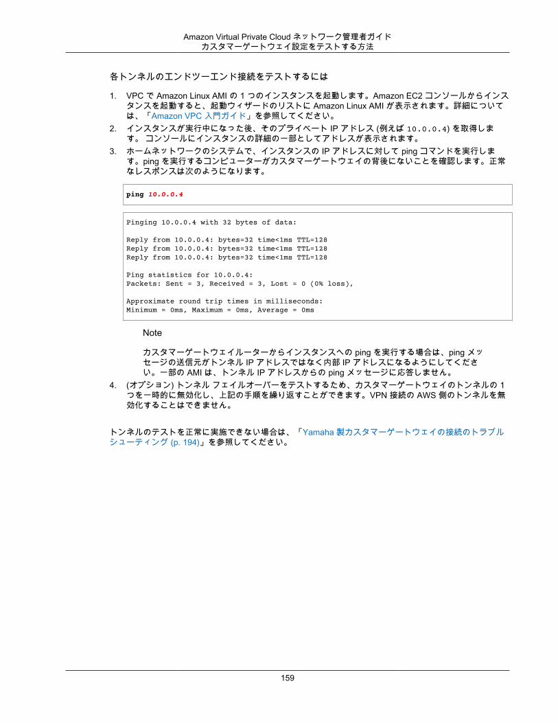
Amazon Virtual Private Cloud ネットワーク管理者ガイドカスタマーゲートウェイ設定をテストする方法
各トンネルのエンドツーエンド接続をテストするには
1. VPC で Amazon Linux AMI の 1 つのインスタンスを起動します。Amazon EC2 コンソールからインスタンスを起動すると、起動ウィザードのリストに Amazon Linux AMI が表示されます。詳細については、「Amazon VPC 入門ガイド」を参照してください。
2. インスタンスが実行中になった後、そのプライベート IP アドレス (例えば 10.0.0.4) を取得します。 コンソールにインスタンスの詳細の一部としてアドレスが表示されます。
3. ホームネットワークのシステムで、インスタンスの IP アドレスに対して ping コマンドを実行します。ping を実行するコンピューターがカスタマーゲートウェイの背後にないことを確認します。正常なレスポンスは次のようになります。
ping 10.0.0.4
Pinging 10.0.0.4 with 32 bytes of data:
Reply from 10.0.0.4: bytes=32 time<1ms TTL=128Reply from 10.0.0.4: bytes=32 time<1ms TTL=128Reply from 10.0.0.4: bytes=32 time<1ms TTL=128
Ping statistics for 10.0.0.4:Packets: Sent = 3, Received = 3, Lost = 0 (0% loss),
Approximate round trip times in milliseconds:Minimum = 0ms, Maximum = 0ms, Average = 0ms
Note
カスタマーゲートウェイルーターからインスタンスへの ping を実行する場合は、ping メッセージの送信元がトンネル IP アドレスではなく内部 IP アドレスになるようにしてください。一部の AMI は、トンネル IP アドレスからの ping メッセージに応答しません。
4. (オプション) トンネル フェイルオーバーをテストするため、カスタマーゲートウェイのトンネルの 1つを一時的に無効化し、上記の手順を繰り返すことができます。VPN 接続の AWS 側のトンネルを無効化することはできません。
トンネルのテストを正常に実施できない場合は、「Yamaha 製カスタマーゲートウェイの接続のトラブルシューティング (p. 194)」を参照してください。
159
Amazon Virtual Private Cloud ネットワーク管理者ガイド
例: ボーダーゲートウェイプロトコルを使用した一般的なカスタマーゲートウェイ
トピック• カスタマーゲートウェイの概要 (p. 161)• カスタマーゲートウェイの詳細と設定例 (p. 161)• カスタマーゲートウェイ設定をテストする方法 (p. 166)
このガイドでこれまで説明したタイプとは異なるカスタマーゲートウェイを使用する場合は、任意のカスタマーゲートウェイの設定に使用できる一般的な情報が統合チームから提供されます。このセクションでは、その情報の例を紹介します。
2 つの図で設定例を紹介します。最初の図はカスタマーゲートウェイのレイアウトの概要を表し、2 番目の図はこの設定例の詳細を表しています。統合チームから受け取った実際の設定情報を使用して、カスタマーゲートウェイに適用する必要があります。
160
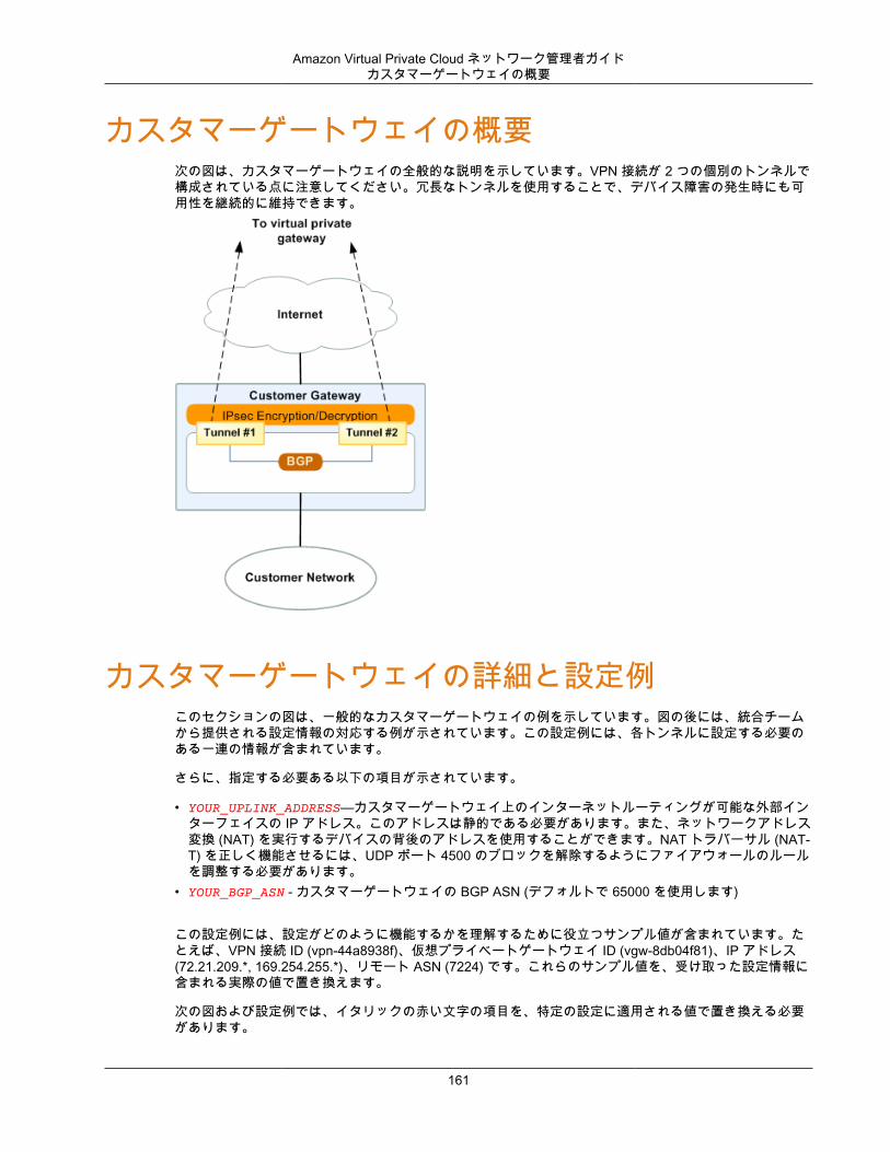
Amazon Virtual Private Cloud ネットワーク管理者ガイドカスタマーゲートウェイの概要
カスタマーゲートウェイの概要次の図は、カスタマーゲートウェイの全般的な説明を示しています。VPN 接続が 2 つの個別のトンネルで構成されている点に注意してください。冗長なトンネルを使用することで、デバイス障害の発生時にも可用性を継続的に維持できます。
カスタマーゲートウェイの詳細と設定例このセクションの図は、一般的なカスタマーゲートウェイの例を示しています。図の後には、統合チームから提供される設定情報の対応する例が示されています。この設定例には、各トンネルに設定する必要のある一連の情報が含まれています。
さらに、指定する必要ある以下の項目が示されています。
• YOUR_UPLINK_ADDRESS—カスタマーゲートウェイ上のインターネットルーティングが可能な外部インターフェイスの IP アドレス。このアドレスは静的である必要があります。また、ネットワークアドレス変換 (NAT) を実行するデバイスの背後のアドレスを使用することができます。NAT トラバーサル (NAT-T) を正しく機能させるには、UDP ポート 4500 のブロックを解除するようにファイアウォールのルールを調整する必要があります。
• YOUR_BGP_ASN - カスタマーゲートウェイの BGP ASN (デフォルトで 65000 を使用します)
この設定例には、設定がどのように機能するかを理解するために役立つサンプル値が含まれています。たとえば、VPN 接続 ID (vpn-44a8938f)、仮想プライベートゲートウェイ ID (vgw-8db04f81)、IP アドレス(72.21.209.*, 169.254.255.*)、リモート ASN (7224) です。これらのサンプル値を、受け取った設定情報に含まれる実際の値で置き換えます。
次の図および設定例では、イタリックの赤い文字の項目を、特定の設定に適用される値で置き換える必要があります。
161
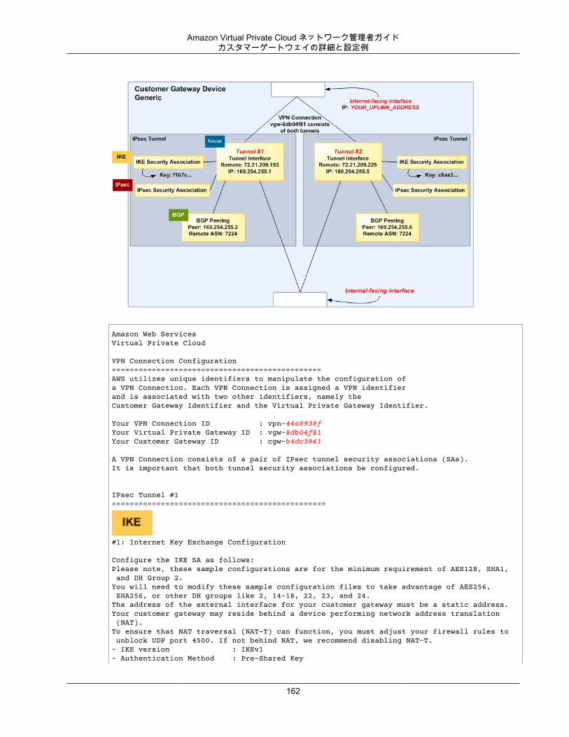
Amazon Virtual Private Cloud ネットワーク管理者ガイドカスタマーゲートウェイの詳細と設定例
Amazon Web ServicesVirtual Private Cloud
VPN Connection Configuration===============================================AWS utilizes unique identifiers to manipulate the configuration of a VPN Connection. Each VPN Connection is assigned a VPN identifier and is associated with two other identifiers, namely the Customer Gateway Identifier and the Virtual Private Gateway Identifier.
Your VPN Connection ID : vpn-44a8938fYour Virtual Private Gateway ID : vgw-8db04f81Your Customer Gateway ID : cgw-b4dc3961
A VPN Connection consists of a pair of IPsec tunnel security associations (SAs). It is important that both tunnel security associations be configured.
IPsec Tunnel #1================================================
#1: Internet Key Exchange Configuration
Configure the IKE SA as follows:Please note, these sample configurations are for the minimum requirement of AES128, SHA1, and DH Group 2.You will need to modify these sample configuration files to take advantage of AES256, SHA256, or other DH groups like 2, 14-18, 22, 23, and 24.The address of the external interface for your customer gateway must be a static address. Your customer gateway may reside behind a device performing network address translation (NAT).To ensure that NAT traversal (NAT-T) can function, you must adjust your firewall rules to unblock UDP port 4500. If not behind NAT, we recommend disabling NAT-T.- IKE version : IKEv1- Authentication Method : Pre-Shared Key
162
Amazon Virtual Private Cloud ネットワーク管理者ガイドカスタマーゲートウェイの詳細と設定例
- Pre-Shared Key : plain-text-password1- Authentication Algorithm : sha1- Encryption Algorithm : aes-128-cbc- Lifetime : 28800 seconds- Phase 1 Negotiation Mode : main- Diffie-Hellman : Group 2
#2: IPsec Configuration
Configure the IPsec SA as follows:Please note, you may use these additionally supported IPSec parameters for encryption like AES256 and other DH groups like 2, 5, 14-18, 22, 23, and 24.- Protocol : esp- Authentication Algorithm : hmac-sha1-96- Encryption Algorithm : aes-128-cbc- Lifetime : 3600 seconds- Mode : tunnel- Perfect Forward Secrecy : Diffie-Hellman Group 2
IPsec Dead Peer Detection (DPD) will be enabled on the AWS Endpoint. Werecommend configuring DPD on your endpoint as follows:- DPD Interval : 10- DPD Retries : 3
IPsec ESP (Encapsulating Security Payload) inserts additionalheaders to transmit packets. These headers require additional space, which reduces the amount of space available to transmit application data.To limit the impact of this behavior, we recommend the following configuration on your Customer Gateway:- TCP MSS Adjustment : 1387 bytes- Clear Don't Fragment Bit : enabled- Fragmentation : Before encryption
#3: Tunnel Interface Configuration
Your Customer Gateway must be configured with a tunnel interface that isassociated with the IPsec tunnel. All traffic transmitted to the tunnelinterface is encrypted and transmitted to the Virtual Private Gateway.
The Customer Gateway and Virtual Private Gateway each have two addresses that relateto this IPsec tunnel. Each contains an outside address, upon which encryptedtraffic is exchanged. Each also contain an inside address associated withthe tunnel interface.
The Customer Gateway outside IP address was provided when the Customer Gatewaywas created. Changing the IP address requires the creation of a newCustomer Gateway.
The Customer Gateway inside IP address should be configured on your tunnelinterface.
Outside IP Addresses:- Customer Gateway: : YOUR_UPLINK_ADDRESS - Virtual Private Gateway : 72.21.209.193
Inside IP Addresses- Customer Gateway : 169.254.255.2/30- Virtual Private Gateway : 169.254.255.1/30
163
Amazon Virtual Private Cloud ネットワーク管理者ガイドカスタマーゲートウェイの詳細と設定例
Configure your tunnel to fragment at the optimal size:- Tunnel interface MTU : 1436 bytes
#4: Border Gateway Protocol (BGP) Configuration:
The Border Gateway Protocol (BGPv4) is used within the tunnel, between the insideIP addresses, to exchange routes from the VPC to your home network. EachBGP router has an Autonomous System Number (ASN). Your ASN was provided to AWS when the Customer Gateway was created.
BGP Configuration Options:- Customer Gateway ASN : YOUR_BGP_ASN - Virtual Private Gateway ASN : 7224- Neighbor IP Address : 169.254.255.1- Neighbor Hold Time : 30
Configure BGP to announce routes to the Virtual Private Gateway. The gatewaywill announce prefixes to your customer gateway based upon the prefix you assigned to the VPC at creation time.
IPsec Tunnel #2=====================================================
#1: Internet Key Exchange Configuration
Configure the IKE SA as follows:Please note, these sample configurations are for the minimum requirement of AES128, SHA1, and DH Group 2.You will need to modify these sample configuration files to take advantage of AES256, SHA256, or other DH groups like 2, 14-18, 22, 23, and 24.The address of the external interface for your customer gateway must be a static address. Your customer gateway may reside behind a device performing network address translation (NAT).To ensure that NAT traversal (NAT-T) can function, you must adjust your firewall rules to unblock UDP port 4500. If not behind NAT, we recommend disabling NAT-T.- IKE version : IKEv1- Authentication Method : Pre-Shared Key - Pre-Shared Key : plain-text-password2- Authentication Algorithm : sha1- Encryption Algorithm : aes-128-cbc- Lifetime : 28800 seconds- Phase 1 Negotiation Mode : main- Diffie-Hellman : Group 2
#2: IPsec Configuration
Configure the IPsec SA as follows:Please note, you may use these additionally supported IPSec parameters for encryption like AES256 and other DH groups like 2, 5, 14-18, 22, 23, and 24.- Protocol : esp- Authentication Algorithm : hmac-sha1-96- Encryption Algorithm : aes-128-cbc- Lifetime : 3600 seconds- Mode : tunnel- Perfect Forward Secrecy : Diffie-Hellman Group 2
IPsec Dead Peer Detection (DPD) will be enabled on the AWS Endpoint. We
164
Amazon Virtual Private Cloud ネットワーク管理者ガイドカスタマーゲートウェイの詳細と設定例
recommend configuring DPD on your endpoint as follows:- DPD Interval : 10- DPD Retries : 3
IPsec ESP (Encapsulating Security Payload) inserts additionalheaders to transmit packets. These headers require additional space, which reduces the amount of space available to transmit application data.To limit the impact of this behavior, we recommend the following configuration on your Customer Gateway:- TCP MSS Adjustment : 1387 bytes- Clear Don't Fragment Bit : enabled- Fragmentation : Before encryption
#3: Tunnel Interface Configuration
Your Customer Gateway must be configured with a tunnel interface that isassociated with the IPsec tunnel. All traffic transmitted to the tunnelinterface is encrypted and transmitted to the Virtual Private Gateway.
The Customer Gateway and Virtual Private Gateway each have two addresses that relateto this IPsec tunnel. Each contains an outside address, upon which encryptedtraffic is exchanged. Each also contain an inside address associated withthe tunnel interface.
The Customer Gateway outside IP address was provided when the Customer Gatewaywas created. Changing the IP address requires the creation of a newCustomer Gateway.
The Customer Gateway inside IP address should be configured on your tunnelinterface.
Outside IP Addresses:- Customer Gateway: : YOUR_UPLINK_ADDRESS - Virtual Private Gateway : 72.21.209.193
Inside IP Addresses- Customer Gateway : 169.254.255.6/30- Virtual Private Gateway : 169.254.255.5/30
Configure your tunnel to fragment at the optimal size:- Tunnel interface MTU : 1436 bytes
" #4: Border Gateway Protocol (BGP) Configuration:
The Border Gateway Protocol (BGPv4) is used within the tunnel, between the insideIP addresses, to exchange routes from the VPC to your home network. EachBGP router has an Autonomous System Number (ASN). Your ASN was provided to AWS when the Customer Gateway was created.
BGP Configuration Options:- Customer Gateway ASN : YOUR_BGP_ASN - Virtual Private Gateway ASN : 7224- Neighbor IP Address : 169.254.255.5- Neighbor Hold Time : 30
Configure BGP to announce routes to the Virtual Private Gateway. The gatewaywill announce prefixes to your customer gateway based upon the prefix you assigned to the VPC at creation time.
165

Amazon Virtual Private Cloud ネットワーク管理者ガイドカスタマーゲートウェイ設定をテストする方法
カスタマーゲートウェイ設定をテストする方法各トンネルに対して、ゲートウェイ設定をテストすることができます。
各トンネルのカスタマーゲートウェイ設定をテストするには
1. カスタマーゲートウェイで、BGP ステータスが Active であるかどうかを確認します。
BGP ピアがアクティブになるまでに約 30 秒かかります。2. カスタマーゲートウェイが仮想プライベートゲートウェイへのルートをアドバタイズしていることを
確認します。このルートは、デフォルトルート (0.0.0.0/0) の場合と、任意で特定したルートの場合があります。
正しく設定されている場合、BGP ピアは、VPC 統合チームが VPC 用に指定したプレフィックス (たとえば、10.0.0.0/24) に対応する仮想プライベートゲートウェイから 1 つのルートを受け取ります。BGPピアが確立された場合は、プレフィックスを受け取り、プレフィックスをアドバタイズして、トンネルが正しく設定されます。両方のトンネルがこの状態であることを確認します。
次に、VPC でインスタンスを起動し、ホームネットワークからインスタンスへの ping を実行して、各トンネルの接続をテストする必要があります。開始する前に、以下を確認してください。
• ping リクエストに応答する AMI を使用します。Amazon Linux AMI のいずれかを使用することをお勧めします。
• インスタンスのセキュリティグループとネットワーク ACL を設定し、インバウンド ICMP トラフィックを有効にします。
• VPN 接続用のルーティングを設定していることを確認します。サブネットのルートテーブルに仮想プライベートゲートウェイへのルートが含まれている必要があります。詳細については、Amazon VPC ユーザーガイド の「ルートテーブルでルート伝達を有効にする」を参照してください。
各トンネルのエンドツーエンド接続をテストするには
1. VPC で Amazon Linux AMI の 1 つのインスタンスを起動します。Amazon EC2 コンソールからインスタンスを起動すると、起動ウィザードのリストに Amazon Linux AMI が表示されます。詳細については、「Amazon VPC 入門ガイド」を参照してください。
2. インスタンスが実行中になった後、そのプライベート IP アドレス (例えば 10.0.0.4) を取得します。 コンソールにインスタンスの詳細の一部としてアドレスが表示されます。
3. ホームネットワークのシステムで、インスタンスの IP アドレスに対して ping コマンドを実行します。ping を実行するコンピューターがカスタマーゲートウェイの背後にないことを確認します。正常なレスポンスは次のようになります。
ping 10.0.0.4
Pinging 10.0.0.4 with 32 bytes of data:
Reply from 10.0.0.4: bytes=32 time<1ms TTL=128Reply from 10.0.0.4: bytes=32 time<1ms TTL=128Reply from 10.0.0.4: bytes=32 time<1ms TTL=128
Ping statistics for 10.0.0.4:Packets: Sent = 3, Received = 3, Lost = 0 (0% loss),
Approximate round trip times in milliseconds:Minimum = 0ms, Maximum = 0ms, Average = 0ms
166

Amazon Virtual Private Cloud ネットワーク管理者ガイドカスタマーゲートウェイ設定をテストする方法
Note
カスタマーゲートウェイルーターからインスタンスへの ping を実行する場合は、ping メッセージの送信元がトンネル IP アドレスではなく内部 IP アドレスになるようにしてください。一部の AMI は、トンネル IP アドレスからの ping メッセージに応答しません。
4. (オプション) トンネル フェイルオーバーをテストするため、カスタマーゲートウェイのトンネルの 1つを一時的に無効化し、上記の手順を繰り返すことができます。VPN 接続の AWS 側のトンネルを無効化することはできません。
トンネルのテストを正常に実施できない場合は、「ボーダーゲートウェイプロトコルを使用した一般的なデバイスのカスタマーゲートウェイ接続のトラブルシューティング (p. 197)」を参照してください。
167
Amazon Virtual Private Cloud ネットワーク管理者ガイド
例: ボーダーゲートウェイプロトコルを使用しない一般的なカスタマーゲートウェイ
トピック• カスタマーゲートウェイの概要 (p. 169)• カスタマーゲートウェイの詳細と設定例 (p. 169)• カスタマーゲートウェイ設定をテストする方法 (p. 174)
このガイドでこれまで説明したタイプとは異なるカスタマーゲートウェイを使用する場合は、任意のカスタマーゲートウェイの設定に使用できる一般的な情報が統合チームから提供されます。このセクションでは、その情報の例を紹介します。
2 つの図で設定例を紹介します。最初の図はカスタマーゲートウェイのレイアウトの概要を表し、2 番目の図はこの設定例の詳細を表しています。統合チームから受け取った実際の設定情報を使用して、カスタマーゲートウェイに適用する必要があります。
168
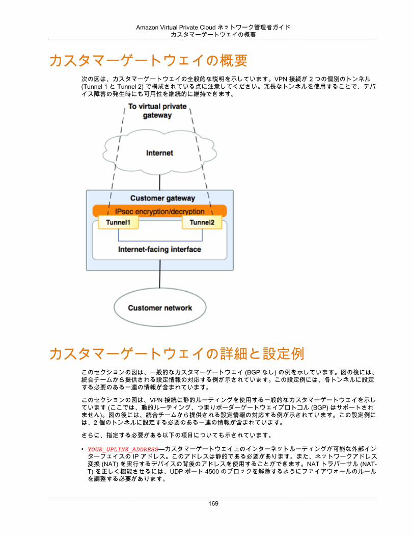
Amazon Virtual Private Cloud ネットワーク管理者ガイドカスタマーゲートウェイの概要
カスタマーゲートウェイの概要次の図は、カスタマーゲートウェイの全般的な説明を示しています。VPN 接続が 2 つの個別のトンネル(Tunnel 1 と Tunnel 2) で構成されている点に注意してください。冗長なトンネルを使用することで、デバイス障害の発生時にも可用性を継続的に維持できます。
カスタマーゲートウェイの詳細と設定例このセクションの図は、一般的なカスタマーゲートウェイ (BGP なし) の例を示しています。図の後には、統合チームから提供される設定情報の対応する例が示されています。この設定例には、各トンネルに設定する必要のある一連の情報が含まれています。
このセクションの図は、VPN 接続に静的ルーティングを使用する一般的なカスタマーゲートウェイを示しています (ここでは、動的ルーティング、つまりボーダーゲートウェイプロトコル (BGP) はサポートされません)。図の後には、統合チームから提供される設定情報の対応する例が示されています。この設定例には、2 個のトンネルに設定する必要のある一連の情報が含まれています。
さらに、指定する必要がある以下の項目についても示されています。
• YOUR_UPLINK_ADDRESS—カスタマーゲートウェイ上のインターネットルーティングが可能な外部インターフェイスの IP アドレス。このアドレスは静的である必要があります。また、ネットワークアドレス変換 (NAT) を実行するデバイスの背後のアドレスを使用することができます。NAT トラバーサル (NAT-T) を正しく機能させるには、UDP ポート 4500 のブロックを解除するようにファイアウォールのルールを調整する必要があります。
169
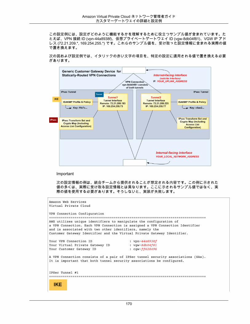
Amazon Virtual Private Cloud ネットワーク管理者ガイドカスタマーゲートウェイの詳細と設定例
この設定例には、設定がどのように機能するかを理解するために役立つサンプル値が含まれています。たとえば、VPN 接続 ID (vpn-44a8938f)、仮想プライベートゲートウェイ ID (vgw-8db04f81)、VGW IP アドレス (72.21.209.*, 169.254.255.*) です。これらのサンプル値を、受け取った設定情報に含まれる実際の値で置き換えます。
次の図および設定例では、イタリックの赤い文字の項目を、特定の設定に適用される値で置き換える必要があります。
Important
次の設定情報の例は、統合チームから提供されることが想定される内容です。この例に示された値の多くは、実際に受け取る設定情報とは異なります。ここに示されるサンプル値ではなく、実際の値を使用する必要があります。そうしないと、実装が失敗します。
Amazon Web ServicesVirtual Private Cloud
VPN Connection Configuration================================================================================AWS utilizes unique identifiers to manipulate the configuration ofa VPN Connection. Each VPN Connection is assigned a VPN Connection Identifierand is associated with two other identifiers, namely theCustomer Gateway Identifier and the Virtual Private Gateway Identifier.
Your VPN Connection ID : vpn-44a8938fYour Virtual Private Gateway ID : vgw-8db04f81Your Customer Gateway ID : cgw-ff628496
A VPN Connection consists of a pair of IPSec tunnel security associations (SAs).It is important that both tunnel security associations be configured.
IPSec Tunnel #1================================================================================
170
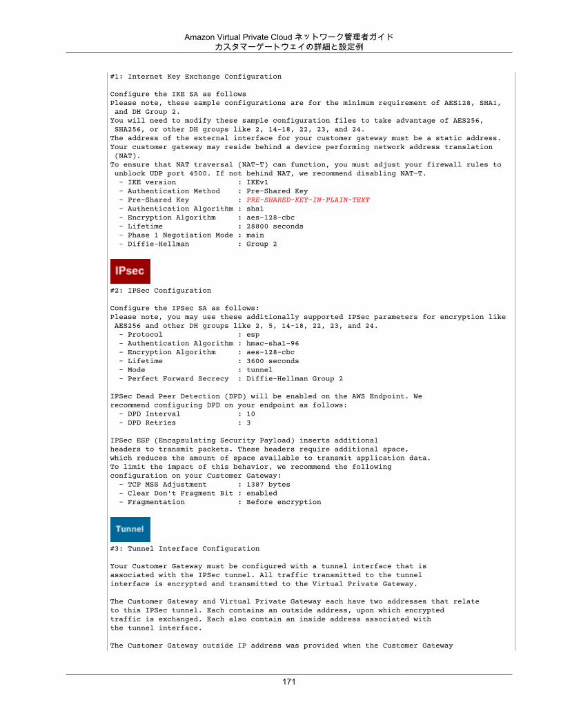
Amazon Virtual Private Cloud ネットワーク管理者ガイドカスタマーゲートウェイの詳細と設定例
#1: Internet Key Exchange Configuration
Configure the IKE SA as followsPlease note, these sample configurations are for the minimum requirement of AES128, SHA1, and DH Group 2.You will need to modify these sample configuration files to take advantage of AES256, SHA256, or other DH groups like 2, 14-18, 22, 23, and 24.The address of the external interface for your customer gateway must be a static address. Your customer gateway may reside behind a device performing network address translation (NAT).To ensure that NAT traversal (NAT-T) can function, you must adjust your firewall rules to unblock UDP port 4500. If not behind NAT, we recommend disabling NAT-T. - IKE version : IKEv1 - Authentication Method : Pre-Shared Key - Pre-Shared Key : PRE-SHARED-KEY-IN-PLAIN-TEXT - Authentication Algorithm : sha1 - Encryption Algorithm : aes-128-cbc - Lifetime : 28800 seconds - Phase 1 Negotiation Mode : main - Diffie-Hellman : Group 2
#2: IPSec Configuration
Configure the IPSec SA as follows:Please note, you may use these additionally supported IPSec parameters for encryption like AES256 and other DH groups like 2, 5, 14-18, 22, 23, and 24. - Protocol : esp - Authentication Algorithm : hmac-sha1-96 - Encryption Algorithm : aes-128-cbc - Lifetime : 3600 seconds - Mode : tunnel - Perfect Forward Secrecy : Diffie-Hellman Group 2
IPSec Dead Peer Detection (DPD) will be enabled on the AWS Endpoint. Werecommend configuring DPD on your endpoint as follows: - DPD Interval : 10 - DPD Retries : 3
IPSec ESP (Encapsulating Security Payload) inserts additionalheaders to transmit packets. These headers require additional space,which reduces the amount of space available to transmit application data.To limit the impact of this behavior, we recommend the followingconfiguration on your Customer Gateway: - TCP MSS Adjustment : 1387 bytes - Clear Don't Fragment Bit : enabled - Fragmentation : Before encryption
#3: Tunnel Interface Configuration
Your Customer Gateway must be configured with a tunnel interface that isassociated with the IPSec tunnel. All traffic transmitted to the tunnelinterface is encrypted and transmitted to the Virtual Private Gateway.
The Customer Gateway and Virtual Private Gateway each have two addresses that relateto this IPSec tunnel. Each contains an outside address, upon which encryptedtraffic is exchanged. Each also contain an inside address associated withthe tunnel interface.
The Customer Gateway outside IP address was provided when the Customer Gateway
171
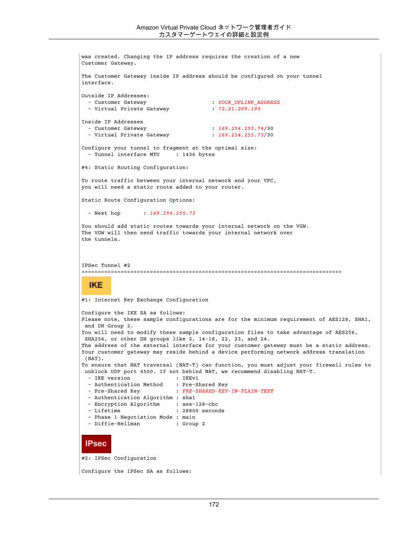
Amazon Virtual Private Cloud ネットワーク管理者ガイドカスタマーゲートウェイの詳細と設定例
was created. Changing the IP address requires the creation of a newCustomer Gateway.
The Customer Gateway inside IP address should be configured on your tunnelinterface.
Outside IP Addresses: - Customer Gateway : YOUR_UPLINK_ADDRESS - Virtual Private Gateway : 72.21.209.193
Inside IP Addresses - Customer Gateway : 169.254.255.74/30 - Virtual Private Gateway : 169.254.255.73/30
Configure your tunnel to fragment at the optimal size: - Tunnel interface MTU : 1436 bytes #4: Static Routing Configuration:
To route traffic between your internal network and your VPC,you will need a static route added to your router.
Static Route Configuration Options:
- Next hop : 169.254.255.73
You should add static routes towards your internal network on the VGW.The VGW will then send traffic towards your internal network overthe tunnels.
IPSec Tunnel #2 ================================================================================
#1: Internet Key Exchange Configuration
Configure the IKE SA as follows:Please note, these sample configurations are for the minimum requirement of AES128, SHA1, and DH Group 2.You will need to modify these sample configuration files to take advantage of AES256, SHA256, or other DH groups like 2, 14-18, 22, 23, and 24.The address of the external interface for your customer gateway must be a static address. Your customer gateway may reside behind a device performing network address translation (NAT).To ensure that NAT traversal (NAT-T) can function, you must adjust your firewall rules to unblock UDP port 4500. If not behind NAT, we recommend disabling NAT-T. - IKE version : IKEv1 - Authentication Method : Pre-Shared Key - Pre-Shared Key : PRE-SHARED-KEY-IN-PLAIN-TEXT - Authentication Algorithm : sha1 - Encryption Algorithm : aes-128-cbc - Lifetime : 28800 seconds - Phase 1 Negotiation Mode : main - Diffie-Hellman : Group 2
#2: IPSec Configuration
Configure the IPSec SA as follows:
172
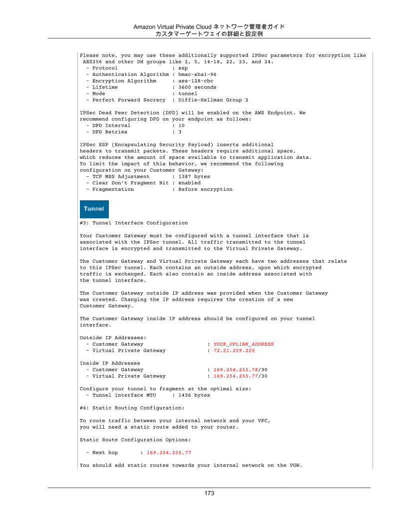
Amazon Virtual Private Cloud ネットワーク管理者ガイドカスタマーゲートウェイの詳細と設定例
Please note, you may use these additionally supported IPSec parameters for encryption like AES256 and other DH groups like 2, 5, 14-18, 22, 23, and 24. - Protocol : esp - Authentication Algorithm : hmac-sha1-96 - Encryption Algorithm : aes-128-cbc - Lifetime : 3600 seconds - Mode : tunnel - Perfect Forward Secrecy : Diffie-Hellman Group 2
IPSec Dead Peer Detection (DPD) will be enabled on the AWS Endpoint. Werecommend configuring DPD on your endpoint as follows: - DPD Interval : 10 - DPD Retries : 3
IPSec ESP (Encapsulating Security Payload) inserts additionalheaders to transmit packets. These headers require additional space,which reduces the amount of space available to transmit application data.To limit the impact of this behavior, we recommend the followingconfiguration on your Customer Gateway: - TCP MSS Adjustment : 1387 bytes - Clear Don't Fragment Bit : enabled - Fragmentation : Before encryption
#3: Tunnel Interface Configuration
Your Customer Gateway must be configured with a tunnel interface that isassociated with the IPSec tunnel. All traffic transmitted to the tunnelinterface is encrypted and transmitted to the Virtual Private Gateway.
The Customer Gateway and Virtual Private Gateway each have two addresses that relateto this IPSec tunnel. Each contains an outside address, upon which encryptedtraffic is exchanged. Each also contain an inside address associated withthe tunnel interface.
The Customer Gateway outside IP address was provided when the Customer Gatewaywas created. Changing the IP address requires the creation of a newCustomer Gateway.
The Customer Gateway inside IP address should be configured on your tunnelinterface.
Outside IP Addresses: - Customer Gateway : YOUR_UPLINK_ADDRESS - Virtual Private Gateway : 72.21.209.225
Inside IP Addresses - Customer Gateway : 169.254.255.78/30 - Virtual Private Gateway : 169.254.255.77/30
Configure your tunnel to fragment at the optimal size: - Tunnel interface MTU : 1436 bytes #4: Static Routing Configuration:
To route traffic between your internal network and your VPC,you will need a static route added to your router.
Static Route Configuration Options:
- Next hop : 169.254.255.77
You should add static routes towards your internal network on the VGW.
173
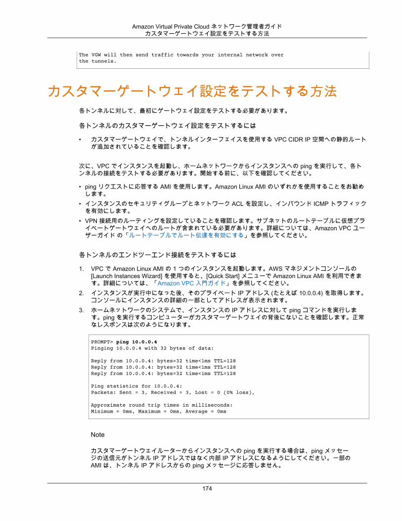
Amazon Virtual Private Cloud ネットワーク管理者ガイドカスタマーゲートウェイ設定をテストする方法
The VGW will then send traffic towards your internal network overthe tunnels.
カスタマーゲートウェイ設定をテストする方法各トンネルに対して、最初にゲートウェイ設定をテストする必要があります。
各トンネルのカスタマーゲートウェイ設定をテストするには
• カスタマーゲートウェイで、トンネルインターフェイスを使用する VPC CIDR IP 空間への静的ルートが追加されていることを確認します。
次に、VPC でインスタンスを起動し、ホームネットワークからインスタンスへの ping を実行して、各トンネルの接続をテストする必要があります。開始する前に、以下を確認してください。
• ping リクエストに応答する AMI を使用します。Amazon Linux AMI のいずれかを使用することをお勧めします。
• インスタンスのセキュリティグループとネットワーク ACL を設定し、インバウンド ICMP トラフィックを有効にします。
• VPN 接続用のルーティングを設定していることを確認します。サブネットのルートテーブルに仮想プライベートゲートウェイへのルートが含まれている必要があります。詳細については、Amazon VPC ユーザーガイド の「ルートテーブルでルート伝達を有効にする」を参照してください。
各トンネルのエンドツーエンド接続をテストするには
1. VPC で Amazon Linux AMI の 1 つのインスタンスを起動します。AWS マネジメントコンソールの[Launch Instances Wizard] を使用すると、[Quick Start] メニューで Amazon Linux AMI を利用できます。詳細については、「Amazon VPC 入門ガイド」を参照してください。
2. インスタンスが実行中になった後、そのプライベート IP アドレス (たとえば 10.0.0.4) を取得します。コンソールにインスタンスの詳細の一部としてアドレスが表示されます。
3. ホームネットワークのシステムで、インスタンスの IP アドレスに対して ping コマンドを実行します。ping を実行するコンピューターがカスタマーゲートウェイの背後にないことを確認します。正常なレスポンスは次のようになります。
PROMPT> ping 10.0.0.4Pinging 10.0.0.4 with 32 bytes of data:
Reply from 10.0.0.4: bytes=32 time<1ms TTL=128Reply from 10.0.0.4: bytes=32 time<1ms TTL=128Reply from 10.0.0.4: bytes=32 time<1ms TTL=128
Ping statistics for 10.0.0.4:Packets: Sent = 3, Received = 3, Lost = 0 (0% loss),
Approximate round trip times in milliseconds:Minimum = 0ms, Maximum = 0ms, Average = 0ms
Note
カスタマーゲートウェイルーターからインスタンスへの ping を実行する場合は、ping メッセージの送信元がトンネル IP アドレスではなく内部 IP アドレスになるようにしてください。一部のAMI は、トンネル IP アドレスからの ping メッセージに応答しません。
174

Amazon Virtual Private Cloud ネットワーク管理者ガイドカスタマーゲートウェイ設定をテストする方法
トンネルのテストを正常に実施できない場合は、「ボーダーゲートウェイプロトコルを使用した一般的なデバイスのカスタマーゲートウェイ接続のトラブルシューティング (p. 197)」を参照してください。
175
Amazon Virtual Private Cloud ネットワーク管理者ガイドCisco ASA カスタマーゲートウェイの接続
トラブルシューティング以下のトピックには、トンネルの状態が適切でない場合にカスタマーゲートウェイをテストするためのトラブルシューティング情報が含まれています。
トピック• Cisco ASA カスタマーゲートウェイの接続のトラブルシューティング (p. 176)• Cisco IOS カスタマーゲートウェイの接続のトラブルシューティング (p. 179)• ボーダーゲートウェイプロトコル接続を使用しない Cisco IOS カスタマーゲートウェイのトラブル
シューティング (p. 184)• Juniper JunOS カスタマーゲートウェイの接続のトラブルシューティング (p. 188)• Juniper ScreenOS カスタマーゲートウェイの接続のトラブルシューティング (p. 191)• Yamaha 製カスタマーゲートウェイの接続のトラブルシューティング (p. 194)• ボーダーゲートウェイプロトコルを使用した一般的なデバイスのカスタマーゲートウェイ接続のトラ
ブルシューティング (p. 197)• ボーダーゲートウェイプロトコル接続を使用しない一般的なデバイスのカスタマーゲートウェイのト
ラブルシューティング (p. 200)
Cisco ASA カスタマーゲートウェイの接続のトラブルシューティング
Cisco のカスタマーゲートウェイの接続をトラブルシューティングするときに、IKE、IPsec、およびルーティングという 3 つの要素を考慮する必要があります。これらの領域を任意の順序でトラブルシューティングできますが、IKE から (ネットワークスタックの下から) 開始して上に進むことをお勧めします。
Important
一部の Cisco ASA ではアクティブ/スタンバイモードのみがサポートされています。これらのCisco ASA を使用する場合は、アクティブなトンネルを一度に 1 個のみ保持できます。最初のトンネルが利用不可になった場合にのみ、他方のスタンバイトンネルがアクティブになります。スタンバイトンネルはログファイルで次のエラーを生成する場合がありますが、無視できます。Rejecting IPSec tunnel: no matching crypto map entry for remote proxy0.0.0.0/0.0.0.0/0/0 local proxy 0.0.0.0/0.0.0.0/0/0 on interface outside
IKE次のコマンドを使用します。このレスポンスは、IKE が正しく設定されたカスタマーゲートウェイを示しています。
ciscoasa# show crypto isakmp sa
Active SA: 2
176
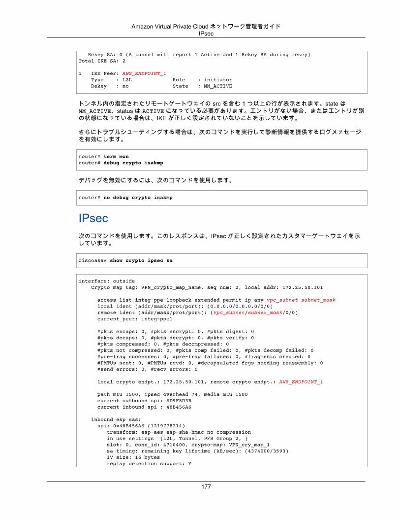
Amazon Virtual Private Cloud ネットワーク管理者ガイドIPsec
Rekey SA: 0 (A tunnel will report 1 Active and 1 Rekey SA during rekey)Total IKE SA: 2
1 IKE Peer: AWS_ENDPOINT_1 Type : L2L Role : initiator Rekey : no State : MM_ACTIVE
トンネル内の指定されたリモートゲートウェイの src を含む 1 つ以上の行が表示されます。state はMM_ACTIVE、status は ACTIVE になっている必要があります。エントリがない場合、またはエントリが別の状態になっている場合は、IKE が正しく設定されていないことを示しています。
さらにトラブルシューティングする場合は、次のコマンドを実行して診断情報を提供するログメッセージを有効にします。
router# term monrouter# debug crypto isakmp
デバッグを無効にするには、次のコマンドを使用します。
router# no debug crypto isakmp
IPsec次のコマンドを使用します。このレスポンスは、IPsec が正しく設定されたカスタマーゲートウェイを示しています。
ciscoasa# show crypto ipsec sa
interface: outside Crypto map tag: VPN_crypto_map_name, seq num: 2, local addr: 172.25.50.101
access-list integ-ppe-loopback extended permit ip any vpc_subnet subnet_mask local ident (addr/mask/prot/port): (0.0.0.0/0.0.0.0/0/0) remote ident (addr/mask/prot/port): (vpc_subnet/subnet_mask/0/0) current_peer: integ-ppe1
#pkts encaps: 0, #pkts encrypt: 0, #pkts digest: 0 #pkts decaps: 0, #pkts decrypt: 0, #pkts verify: 0 #pkts compressed: 0, #pkts decompressed: 0 #pkts not compressed: 0, #pkts comp failed: 0, #pkts decomp failed: 0 #pre-frag successes: 0, #pre-frag failures: 0, #fragments created: 0 #PMTUs sent: 0, #PMTUs rcvd: 0, #decapsulated frgs needing reassembly: 0 #send errors: 0, #recv errors: 0
local crypto endpt.: 172.25.50.101, remote crypto endpt.: AWS_ENDPOINT_1
path mtu 1500, ipsec overhead 74, media mtu 1500 current outbound spi: 6D9F8D3B current inbound spi : 48B456A6
inbound esp sas: spi: 0x48B456A6 (1219778214) transform: esp-aes esp-sha-hmac no compression in use settings ={L2L, Tunnel, PFS Group 2, } slot: 0, conn_id: 4710400, crypto-map: VPN_cry_map_1 sa timing: remaining key lifetime (kB/sec): (4374000/3593) IV size: 16 bytes replay detection support: Y
177
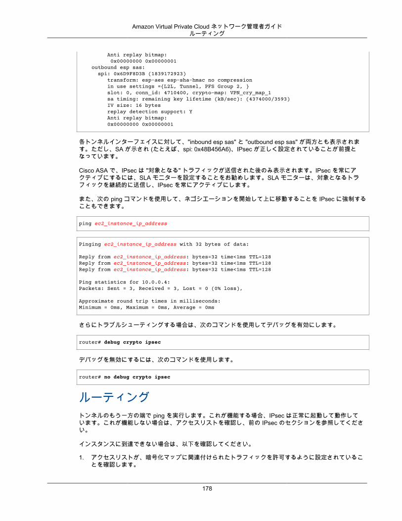
Amazon Virtual Private Cloud ネットワーク管理者ガイドルーティング
Anti replay bitmap: 0x00000000 0x00000001 outbound esp sas: spi: 0x6D9F8D3B (1839172923) transform: esp-aes esp-sha-hmac no compression in use settings ={L2L, Tunnel, PFS Group 2, } slot: 0, conn_id: 4710400, crypto-map: VPN_cry_map_1 sa timing: remaining key lifetime (kB/sec): (4374000/3593) IV size: 16 bytes replay detection support: Y Anti replay bitmap: 0x00000000 0x00000001
各トンネルインターフェイスに対して、"inbound esp sas" と "outbound esp sas" が両方とも表示されます。ただし、SA が示され (たとえば、spi: 0x48B456A6)、IPsec が正しく設定されていることが前提となっています。
Cisco ASA で、IPsec は "対象となる" トラフィックが送信された後のみ表示されます。IPsec を常にアクティブにするには、SLA モニターを設定することをお勧めします。SLA モニターは、対象となるトラフィックを継続的に送信し、IPsec を常にアクティブにします。
また、次の ping コマンドを使用して、ネゴシエーションを開始して上に移動することを IPsec に強制することもできます。
ping ec2_instance_ip_address
Pinging ec2_instance_ip_address with 32 bytes of data:
Reply from ec2_instance_ip_address: bytes=32 time<1ms TTL=128Reply from ec2_instance_ip_address: bytes=32 time<1ms TTL=128Reply from ec2_instance_ip_address: bytes=32 time<1ms TTL=128
Ping statistics for 10.0.0.4:Packets: Sent = 3, Received = 3, Lost = 0 (0% loss),
Approximate round trip times in milliseconds:Minimum = 0ms, Maximum = 0ms, Average = 0ms
さらにトラブルシューティングする場合は、次のコマンドを使用してデバッグを有効にします。
router# debug crypto ipsec
デバッグを無効にするには、次のコマンドを使用します。
router# no debug crypto ipsec
ルーティングトンネルのもう一方の端で ping を実行します。これが機能する場合、IPsec は正常に起動して動作しています。これが機能しない場合は、アクセスリストを確認し、前の IPsec のセクションを参照してください。
インスタンスに到達できない場合は、以下を確認してください。
1. アクセスリストが、暗号化マップに関連付けられたトラフィックを許可するように設定されていることを確認します。
178
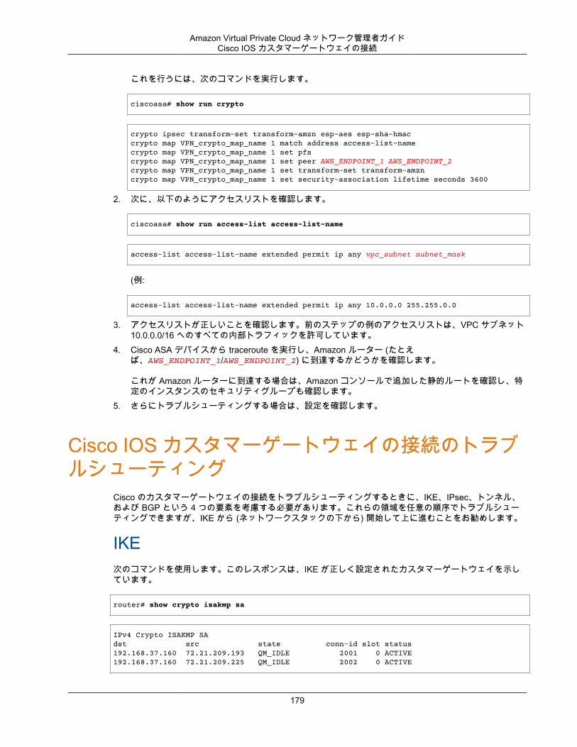
Amazon Virtual Private Cloud ネットワーク管理者ガイドCisco IOS カスタマーゲートウェイの接続
これを行うには、次のコマンドを実行します。
ciscoasa# show run crypto
crypto ipsec transform-set transform-amzn esp-aes esp-sha-hmaccrypto map VPN_crypto_map_name 1 match address access-list-namecrypto map VPN_crypto_map_name 1 set pfscrypto map VPN_crypto_map_name 1 set peer AWS_ENDPOINT_1 AWS_ENDPOINT_2crypto map VPN_crypto_map_name 1 set transform-set transform-amzncrypto map VPN_crypto_map_name 1 set security-association lifetime seconds 3600
2. 次に、以下のようにアクセスリストを確認します。
ciscoasa# show run access-list access-list-name
access-list access-list-name extended permit ip any vpc_subnet subnet_mask
(例:
access-list access-list-name extended permit ip any 10.0.0.0 255.255.0.0
3. アクセスリストが正しいことを確認します。前のステップの例のアクセスリストは、VPC サブネット10.0.0.0/16 へのすべての内部トラフィックを許可しています。
4. Cisco ASA デバイスから traceroute を実行し、Amazon ルーター (たとえば、AWS_ENDPOINT_1/AWS_ENDPOINT_2) に到達するかどうかを確認します。
これが Amazon ルーターに到達する場合は、Amazon コンソールで追加した静的ルートを確認し、特定のインスタンスのセキュリティグループも確認します。
5. さらにトラブルシューティングする場合は、設定を確認します。
Cisco IOS カスタマーゲートウェイの接続のトラブルシューティング
Cisco のカスタマーゲートウェイの接続をトラブルシューティングするときに、IKE、IPsec、トンネル、および BGP という 4 つの要素を考慮する必要があります。これらの領域を任意の順序でトラブルシューティングできますが、IKE から (ネットワークスタックの下から) 開始して上に進むことをお勧めします。
IKE次のコマンドを使用します。このレスポンスは、IKE が正しく設定されたカスタマーゲートウェイを示しています。
router# show crypto isakmp sa
IPv4 Crypto ISAKMP SAdst src state conn-id slot status192.168.37.160 72.21.209.193 QM_IDLE 2001 0 ACTIVE192.168.37.160 72.21.209.225 QM_IDLE 2002 0 ACTIVE
179
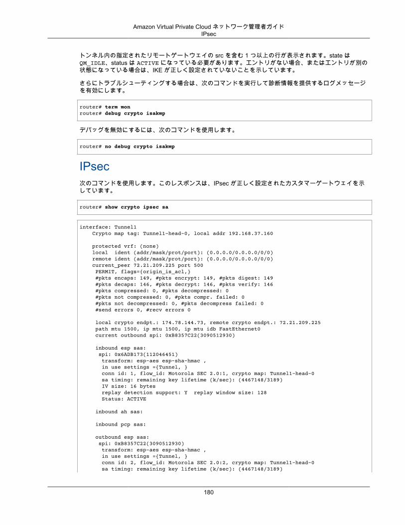
Amazon Virtual Private Cloud ネットワーク管理者ガイドIPsec
トンネル内の指定されたリモートゲートウェイの src を含む 1 つ以上の行が表示されます。state はQM_IDLE、status は ACTIVE になっている必要があります。エントリがない場合、またはエントリが別の状態になっている場合は、IKE が正しく設定されていないことを示しています。
さらにトラブルシューティングする場合は、次のコマンドを実行して診断情報を提供するログメッセージを有効にします。
router# term monrouter# debug crypto isakmp
デバッグを無効にするには、次のコマンドを使用します。
router# no debug crypto isakmp
IPsec次のコマンドを使用します。このレスポンスは、IPsec が正しく設定されたカスタマーゲートウェイを示しています。
router# show crypto ipsec sa
interface: Tunnel1 Crypto map tag: Tunnel1-head-0, local addr 192.168.37.160
protected vrf: (none) local ident (addr/mask/prot/port): (0.0.0.0/0.0.0.0/0/0) remote ident (addr/mask/prot/port): (0.0.0.0/0.0.0.0/0/0) current_peer 72.21.209.225 port 500 PERMIT, flags={origin_is_acl,} #pkts encaps: 149, #pkts encrypt: 149, #pkts digest: 149 #pkts decaps: 146, #pkts decrypt: 146, #pkts verify: 146 #pkts compressed: 0, #pkts decompressed: 0 #pkts not compressed: 0, #pkts compr. failed: 0 #pkts not decompressed: 0, #pkts decompress failed: 0 #send errors 0, #recv errors 0
local crypto endpt.: 174.78.144.73, remote crypto endpt.: 72.21.209.225 path mtu 1500, ip mtu 1500, ip mtu idb FastEthernet0 current outbound spi: 0xB8357C22(3090512930)
inbound esp sas: spi: 0x6ADB173(112046451) transform: esp-aes esp-sha-hmac , in use settings ={Tunnel, } conn id: 1, flow_id: Motorola SEC 2.0:1, crypto map: Tunnel1-head-0 sa timing: remaining key lifetime (k/sec): (4467148/3189) IV size: 16 bytes replay detection support: Y replay window size: 128 Status: ACTIVE
inbound ah sas:
inbound pcp sas:
outbound esp sas: spi: 0xB8357C22(3090512930) transform: esp-aes esp-sha-hmac , in use settings ={Tunnel, } conn id: 2, flow_id: Motorola SEC 2.0:2, crypto map: Tunnel1-head-0 sa timing: remaining key lifetime (k/sec): (4467148/3189)
180
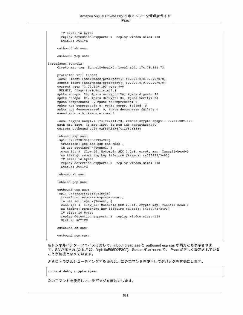
Amazon Virtual Private Cloud ネットワーク管理者ガイドIPsec
IV size: 16 bytes replay detection support: Y replay window size: 128 Status: ACTIVE
outbound ah sas:
outbound pcp sas:
interface: Tunnel2 Crypto map tag: Tunnel2-head-0, local addr 174.78.144.73
protected vrf: (none) local ident (addr/mask/prot/port): (0.0.0.0/0.0.0.0/0/0) remote ident (addr/mask/prot/port): (0.0.0.0/0.0.0.0/0/0) current_peer 72.21.209.193 port 500 PERMIT, flags={origin_is_acl,} #pkts encaps: 26, #pkts encrypt: 26, #pkts digest: 26 #pkts decaps: 24, #pkts decrypt: 24, #pkts verify: 24 #pkts compressed: 0, #pkts decompressed: 0 #pkts not compressed: 0, #pkts compr. failed: 0 #pkts not decompressed: 0, #pkts decompress failed: 0 #send errors 0, #recv errors 0
local crypto endpt.: 174.78.144.73, remote crypto endpt.: 72.21.209.193 path mtu 1500, ip mtu 1500, ip mtu idb FastEthernet0 current outbound spi: 0xF59A3FF6(4120526838)
inbound esp sas: spi: 0xB6720137(3060924727) transform: esp-aes esp-sha-hmac , in use settings ={Tunnel, } conn id: 3, flow_id: Motorola SEC 2.0:3, crypto map: Tunnel2-head-0 sa timing: remaining key lifetime (k/sec): (4387273/3492) IV size: 16 bytes replay detection support: Y replay window size: 128 Status: ACTIVE
inbound ah sas:
inbound pcp sas:
outbound esp sas: spi: 0xF59A3FF6(4120526838) transform: esp-aes esp-sha-hmac , in use settings ={Tunnel, } conn id: 4, flow_id: Motorola SEC 2.0:4, crypto map: Tunnel2-head-0 sa timing: remaining key lifetime (k/sec): (4387273/3492) IV size: 16 bytes replay detection support: Y replay window size: 128 Status: ACTIVE
outbound ah sas:
outbound pcp sas:
各トンネルインターフェイスに対して、inbound esp sas と outbound esp sas が両方とも表示されます。SA が示され (たとえば、"spi: 0xF95D2F3C")、Status が ACTIVE で、IPsec が正しく設定されていることが前提となっています。
さらにトラブルシューティングする場合は、次のコマンドを使用してデバッグを有効にします。
router# debug crypto ipsec
次のコマンドを使用して、デバッグを無効にします。
181
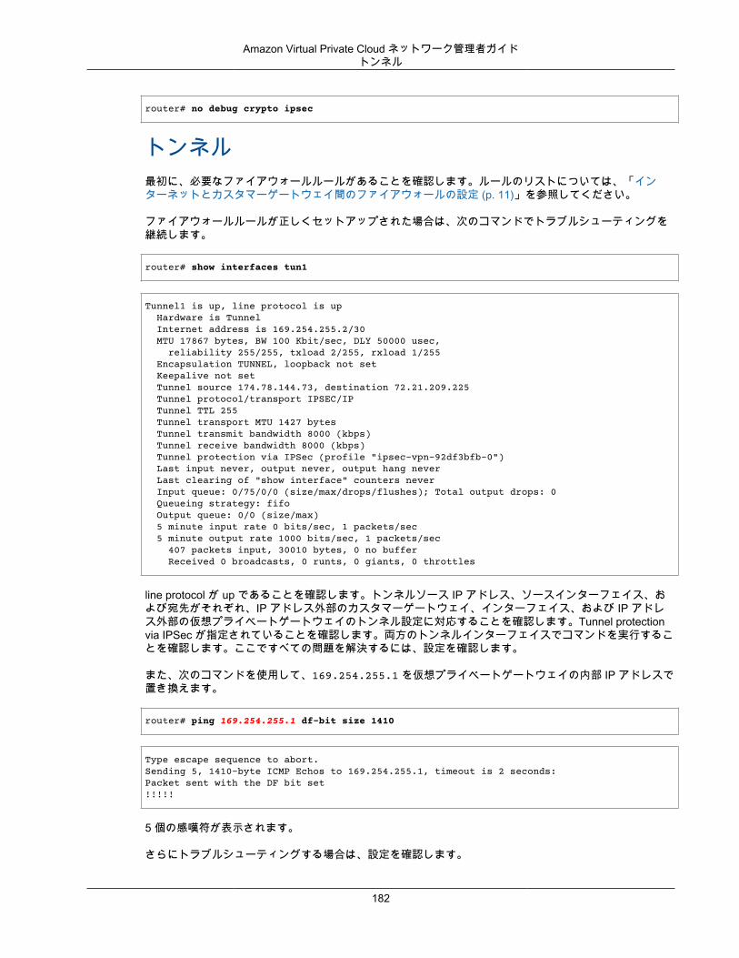
Amazon Virtual Private Cloud ネットワーク管理者ガイドトンネル
router# no debug crypto ipsec
トンネル最初に、必要なファイアウォールルールがあることを確認します。ルールのリストについては、「インターネットとカスタマーゲートウェイ間のファイアウォールの設定 (p. 11)」を参照してください。
ファイアウォールルールが正しくセットアップされた場合は、次のコマンドでトラブルシューティングを継続します。
router# show interfaces tun1
Tunnel1 is up, line protocol is up Hardware is Tunnel Internet address is 169.254.255.2/30 MTU 17867 bytes, BW 100 Kbit/sec, DLY 50000 usec, reliability 255/255, txload 2/255, rxload 1/255 Encapsulation TUNNEL, loopback not set Keepalive not set Tunnel source 174.78.144.73, destination 72.21.209.225 Tunnel protocol/transport IPSEC/IP Tunnel TTL 255 Tunnel transport MTU 1427 bytes Tunnel transmit bandwidth 8000 (kbps) Tunnel receive bandwidth 8000 (kbps) Tunnel protection via IPSec (profile "ipsec-vpn-92df3bfb-0") Last input never, output never, output hang never Last clearing of "show interface" counters never Input queue: 0/75/0/0 (size/max/drops/flushes); Total output drops: 0 Queueing strategy: fifo Output queue: 0/0 (size/max) 5 minute input rate 0 bits/sec, 1 packets/sec 5 minute output rate 1000 bits/sec, 1 packets/sec 407 packets input, 30010 bytes, 0 no buffer Received 0 broadcasts, 0 runts, 0 giants, 0 throttles
line protocol が up であることを確認します。トンネルソース IP アドレス、ソースインターフェイス、および宛先がそれぞれ、IP アドレス外部のカスタマーゲートウェイ、インターフェイス、および IP アドレス外部の仮想プライベートゲートウェイのトンネル設定に対応することを確認します。Tunnel protectionvia IPSec が指定されていることを確認します。両方のトンネルインターフェイスでコマンドを実行することを確認します。ここですべての問題を解決するには、設定を確認します。
また、次のコマンドを使用して、169.254.255.1 を仮想プライベートゲートウェイの内部 IP アドレスで置き換えます。
router# ping 169.254.255.1 df-bit size 1410
Type escape sequence to abort.Sending 5, 1410-byte ICMP Echos to 169.254.255.1, timeout is 2 seconds:Packet sent with the DF bit set!!!!!
5 個の感嘆符が表示されます。
さらにトラブルシューティングする場合は、設定を確認します。
182
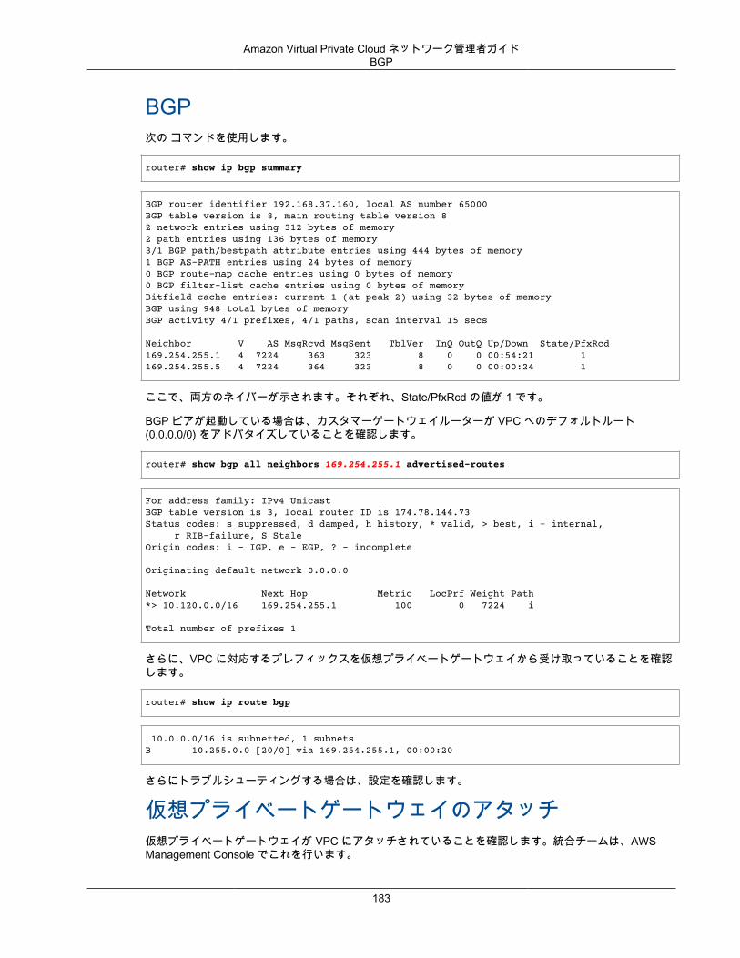
Amazon Virtual Private Cloud ネットワーク管理者ガイドBGP
BGP次の コマンドを使用します。
router# show ip bgp summary
BGP router identifier 192.168.37.160, local AS number 65000BGP table version is 8, main routing table version 82 network entries using 312 bytes of memory2 path entries using 136 bytes of memory3/1 BGP path/bestpath attribute entries using 444 bytes of memory1 BGP AS-PATH entries using 24 bytes of memory0 BGP route-map cache entries using 0 bytes of memory0 BGP filter-list cache entries using 0 bytes of memoryBitfield cache entries: current 1 (at peak 2) using 32 bytes of memoryBGP using 948 total bytes of memoryBGP activity 4/1 prefixes, 4/1 paths, scan interval 15 secs
Neighbor V AS MsgRcvd MsgSent TblVer InQ OutQ Up/Down State/PfxRcd169.254.255.1 4 7224 363 323 8 0 0 00:54:21 1169.254.255.5 4 7224 364 323 8 0 0 00:00:24 1
ここで、両方のネイバーが示されます。それぞれ、State/PfxRcd の値が 1 です。
BGP ピアが起動している場合は、カスタマーゲートウェイルーターが VPC へのデフォルトルート(0.0.0.0/0) をアドバタイズしていることを確認します。
router# show bgp all neighbors 169.254.255.1 advertised-routes
For address family: IPv4 UnicastBGP table version is 3, local router ID is 174.78.144.73Status codes: s suppressed, d damped, h history, * valid, > best, i - internal, r RIB-failure, S StaleOrigin codes: i - IGP, e - EGP, ? - incomplete
Originating default network 0.0.0.0
Network Next Hop Metric LocPrf Weight Path*> 10.120.0.0/16 169.254.255.1 100 0 7224 i
Total number of prefixes 1
さらに、VPC に対応するプレフィックスを仮想プライベートゲートウェイから受け取っていることを確認します。
router# show ip route bgp
10.0.0.0/16 is subnetted, 1 subnetsB 10.255.0.0 [20/0] via 169.254.255.1, 00:00:20
さらにトラブルシューティングする場合は、設定を確認します。
仮想プライベートゲートウェイのアタッチ仮想プライベートゲートウェイが VPC にアタッチされていることを確認します。統合チームは、AWSManagement Console でこれを行います。
183
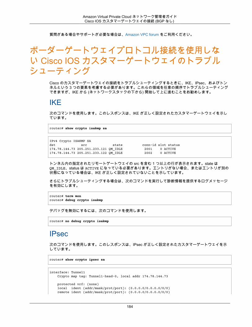
Amazon Virtual Private Cloud ネットワーク管理者ガイドCisco IOS カスタマーゲートウェイの接続 (BGP なし)
質問がある場合やサポートが必要な場合は、Amazon VPC forum をご利用ください。
ボーダーゲートウェイプロトコル接続を使用しない Cisco IOS カスタマーゲートウェイのトラブルシューティング
Cisco のカスタマーゲートウェイの接続をトラブルシューティングするときに、IKE、IPsec、およびトンネルという 3 つの要素を考慮する必要があります。これらの領域を任意の順序でトラブルシューティングできますが、IKE から (ネットワークスタックの下から) 開始して上に進むことをお勧めします。
IKE次のコマンドを使用します。このレスポンスは、IKE が正しく設定されたカスタマーゲートウェイを示しています。
router# show crypto isakmp sa
IPv4 Crypto ISAKMP SAdst src state conn-id slot status174.78.144.73 205.251.233.121 QM_IDLE 2001 0 ACTIVE174.78.144.73 205.251.233.122 QM_IDLE 2002 0 ACTIVE
トンネル内の指定されたリモートゲートウェイの src を含む 1 つ以上の行が表示されます。state はQM_IDLE、status は ACTIVE になっている必要があります。エントリがない場合、またはエントリが別の状態になっている場合は、IKE が正しく設定されていないことを示しています。
さらにトラブルシューティングする場合は、次のコマンドを実行して診断情報を提供するログメッセージを有効にします。
router# term monrouter# debug crypto isakmp
デバッグを無効にするには、次のコマンドを使用します。
router# no debug crypto isakmp
IPsec次のコマンドを使用します。このレスポンスは、IPsec が正しく設定されたカスタマーゲートウェイを示しています。
router# show crypto ipsec sa
interface: Tunnel1 Crypto map tag: Tunnel1-head-0, local addr 174.78.144.73
protected vrf: (none) local ident (addr/mask/prot/port): (0.0.0.0/0.0.0.0/0/0) remote ident (addr/mask/prot/port): (0.0.0.0/0.0.0.0/0/0)
184
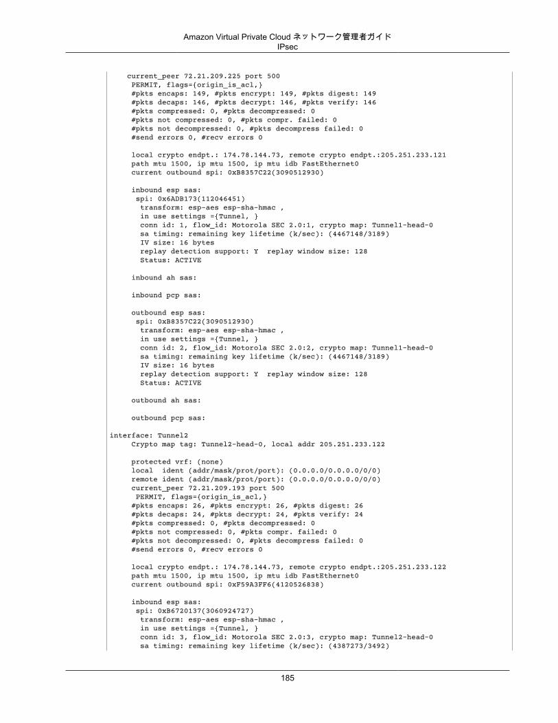
Amazon Virtual Private Cloud ネットワーク管理者ガイドIPsec
current_peer 72.21.209.225 port 500 PERMIT, flags={origin_is_acl,} #pkts encaps: 149, #pkts encrypt: 149, #pkts digest: 149 #pkts decaps: 146, #pkts decrypt: 146, #pkts verify: 146 #pkts compressed: 0, #pkts decompressed: 0 #pkts not compressed: 0, #pkts compr. failed: 0 #pkts not decompressed: 0, #pkts decompress failed: 0 #send errors 0, #recv errors 0
local crypto endpt.: 174.78.144.73, remote crypto endpt.:205.251.233.121 path mtu 1500, ip mtu 1500, ip mtu idb FastEthernet0 current outbound spi: 0xB8357C22(3090512930)
inbound esp sas: spi: 0x6ADB173(112046451) transform: esp-aes esp-sha-hmac , in use settings ={Tunnel, } conn id: 1, flow_id: Motorola SEC 2.0:1, crypto map: Tunnel1-head-0 sa timing: remaining key lifetime (k/sec): (4467148/3189) IV size: 16 bytes replay detection support: Y replay window size: 128 Status: ACTIVE
inbound ah sas:
inbound pcp sas:
outbound esp sas: spi: 0xB8357C22(3090512930) transform: esp-aes esp-sha-hmac , in use settings ={Tunnel, } conn id: 2, flow_id: Motorola SEC 2.0:2, crypto map: Tunnel1-head-0 sa timing: remaining key lifetime (k/sec): (4467148/3189) IV size: 16 bytes replay detection support: Y replay window size: 128 Status: ACTIVE
outbound ah sas:
outbound pcp sas:
interface: Tunnel2 Crypto map tag: Tunnel2-head-0, local addr 205.251.233.122
protected vrf: (none) local ident (addr/mask/prot/port): (0.0.0.0/0.0.0.0/0/0) remote ident (addr/mask/prot/port): (0.0.0.0/0.0.0.0/0/0) current_peer 72.21.209.193 port 500 PERMIT, flags={origin_is_acl,} #pkts encaps: 26, #pkts encrypt: 26, #pkts digest: 26 #pkts decaps: 24, #pkts decrypt: 24, #pkts verify: 24 #pkts compressed: 0, #pkts decompressed: 0 #pkts not compressed: 0, #pkts compr. failed: 0 #pkts not decompressed: 0, #pkts decompress failed: 0 #send errors 0, #recv errors 0
local crypto endpt.: 174.78.144.73, remote crypto endpt.:205.251.233.122 path mtu 1500, ip mtu 1500, ip mtu idb FastEthernet0 current outbound spi: 0xF59A3FF6(4120526838)
inbound esp sas: spi: 0xB6720137(3060924727) transform: esp-aes esp-sha-hmac , in use settings ={Tunnel, } conn id: 3, flow_id: Motorola SEC 2.0:3, crypto map: Tunnel2-head-0 sa timing: remaining key lifetime (k/sec): (4387273/3492)
185
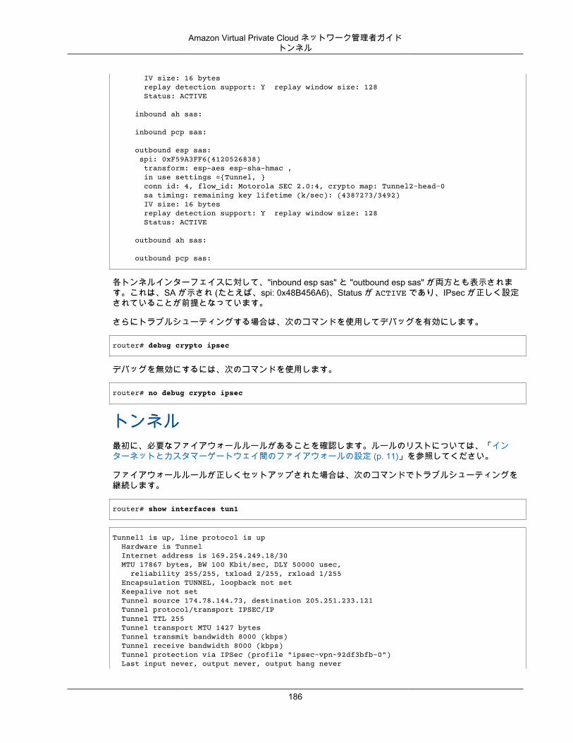
Amazon Virtual Private Cloud ネットワーク管理者ガイドトンネル
IV size: 16 bytes replay detection support: Y replay window size: 128 Status: ACTIVE
inbound ah sas:
inbound pcp sas:
outbound esp sas: spi: 0xF59A3FF6(4120526838) transform: esp-aes esp-sha-hmac , in use settings ={Tunnel, } conn id: 4, flow_id: Motorola SEC 2.0:4, crypto map: Tunnel2-head-0 sa timing: remaining key lifetime (k/sec): (4387273/3492) IV size: 16 bytes replay detection support: Y replay window size: 128 Status: ACTIVE
outbound ah sas:
outbound pcp sas:
各トンネルインターフェイスに対して、"inbound esp sas" と "outbound esp sas" が両方とも表示されます。これは、SA が示され (たとえば、spi: 0x48B456A6)、Status が ACTIVE であり、IPsec が正しく設定されていることが前提となっています。
さらにトラブルシューティングする場合は、次のコマンドを使用してデバッグを有効にします。
router# debug crypto ipsec
デバッグを無効にするには、次のコマンドを使用します。
router# no debug crypto ipsec
トンネル最初に、必要なファイアウォールルールがあることを確認します。ルールのリストについては、「インターネットとカスタマーゲートウェイ間のファイアウォールの設定 (p. 11)」を参照してください。
ファイアウォールルールが正しくセットアップされた場合は、次のコマンドでトラブルシューティングを継続します。
router# show interfaces tun1
Tunnel1 is up, line protocol is up Hardware is Tunnel Internet address is 169.254.249.18/30 MTU 17867 bytes, BW 100 Kbit/sec, DLY 50000 usec, reliability 255/255, txload 2/255, rxload 1/255 Encapsulation TUNNEL, loopback not set Keepalive not set Tunnel source 174.78.144.73, destination 205.251.233.121 Tunnel protocol/transport IPSEC/IP Tunnel TTL 255 Tunnel transport MTU 1427 bytes Tunnel transmit bandwidth 8000 (kbps) Tunnel receive bandwidth 8000 (kbps) Tunnel protection via IPSec (profile "ipsec-vpn-92df3bfb-0") Last input never, output never, output hang never
186
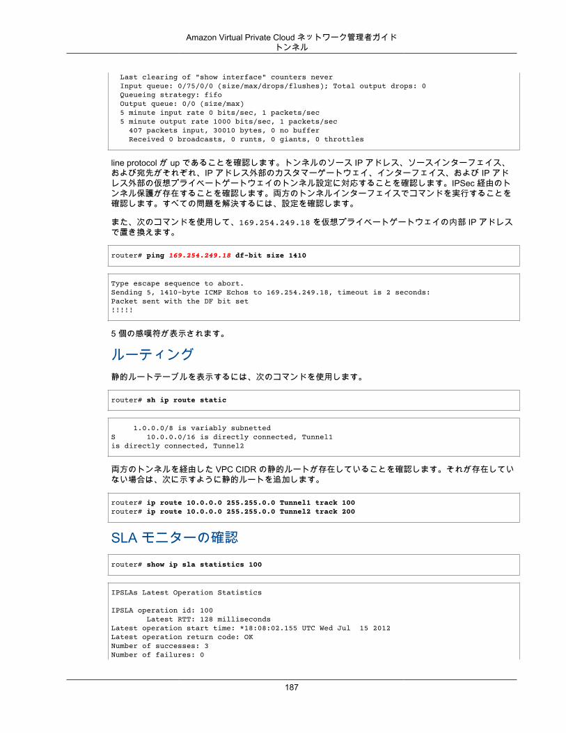
Amazon Virtual Private Cloud ネットワーク管理者ガイドトンネル
Last clearing of "show interface" counters never Input queue: 0/75/0/0 (size/max/drops/flushes); Total output drops: 0 Queueing strategy: fifo Output queue: 0/0 (size/max) 5 minute input rate 0 bits/sec, 1 packets/sec 5 minute output rate 1000 bits/sec, 1 packets/sec 407 packets input, 30010 bytes, 0 no buffer Received 0 broadcasts, 0 runts, 0 giants, 0 throttles
line protocol が up であることを確認します。トンネルのソース IP アドレス、ソースインターフェイス、および宛先がそれぞれ、IP アドレス外部のカスタマーゲートウェイ、インターフェイス、および IP アドレス外部の仮想プライベートゲートウェイのトンネル設定に対応することを確認します。IPSec 経由のトンネル保護が存在することを確認します。両方のトンネルインターフェイスでコマンドを実行することを確認します。すべての問題を解決するには、設定を確認します。
また、次のコマンドを使用して、169.254.249.18 を仮想プライベートゲートウェイの内部 IP アドレスで置き換えます。
router# ping 169.254.249.18 df-bit size 1410
Type escape sequence to abort.Sending 5, 1410-byte ICMP Echos to 169.254.249.18, timeout is 2 seconds:Packet sent with the DF bit set!!!!!
5 個の感嘆符が表示されます。
ルーティング静的ルートテーブルを表示するには、次のコマンドを使用します。
router# sh ip route static
1.0.0.0/8 is variably subnettedS 10.0.0.0/16 is directly connected, Tunnel1is directly connected, Tunnel2
両方のトンネルを経由した VPC CIDR の静的ルートが存在していることを確認します。それが存在していない場合は、次に示すように静的ルートを追加します。
router# ip route 10.0.0.0 255.255.0.0 Tunnel1 track 100 router# ip route 10.0.0.0 255.255.0.0 Tunnel2 track 200
SLA モニターの確認router# show ip sla statistics 100
IPSLAs Latest Operation Statistics
IPSLA operation id: 100 Latest RTT: 128 millisecondsLatest operation start time: *18:08:02.155 UTC Wed Jul 15 2012Latest operation return code: OKNumber of successes: 3Number of failures: 0
187
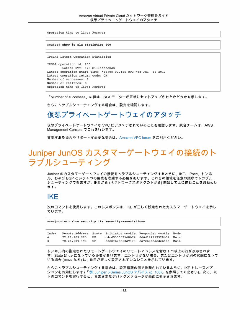
Amazon Virtual Private Cloud ネットワーク管理者ガイド仮想プライベートゲートウェイのアタッチ
Operation time to live: Forever
router# show ip sla statistics 200
IPSLAs Latest Operation Statistics
IPSLA operation id: 200 Latest RTT: 128 millisecondsLatest operation start time: *18:08:02.155 UTC Wed Jul 15 2012Latest operation return code: OKNumber of successes: 3Number of failures: 0Operation time to live: Forever
「Number of successes」の値は、SLA モニターが正常にセットアップされたかどうかを示します。
さらにトラブルシューティングする場合は、設定を確認します。
仮想プライベートゲートウェイのアタッチ仮想プライベートゲートウェイが VPC にアタッチされていることを確認します。統合チームは、AWSManagement Console でこれを行います。
質問がある場合やサポートが必要な場合は、Amazon VPC forum をご利用ください。
Juniper JunOS カスタマーゲートウェイの接続のトラブルシューティング
Juniper のカスタマーゲートウェイの接続をトラブルシューティングするときに、IKE、IPsec、トンネル、および BGP という 4 つの要素を考慮する必要があります。これらの領域を任意の順序でトラブルシューティングできますが、IKE から (ネットワークスタックの下から) 開始して上に進むことをお勧めします。
IKE次のコマンドを使用します。このレスポンスは、IKE が正しく設定されたカスタマーゲートウェイを示しています。
user@router> show security ike security-associations
Index Remote Address State Initiator cookie Responder cookie Mode4 72.21.209.225 UP c4cd953602568b74 0d6d194993328b02 Main3 72.21.209.193 UP b8c8fb7dc68d9173 ca7cb0abaedeb4bb Main
トンネル内の指定されたリモートゲートウェイのリモートアドレスを含む 1 つ以上の行が表示されます。State は UP になっている必要があります。エントリがない場合、またはエントリが別の状態になっている場合 (DOWN など) は、IKE が正しく設定されていないことを示しています。
さらにトラブルシューティングする場合は、設定情報の例で推奨されているように、IKE トレースオプションを有効にします (「例: Juniper J-Series JunOS デバイス (p. 106)」を参照してください)。次に、以下のコマンドを実行すると、さまざまなデバッグメッセージが画面に表示されます。
188
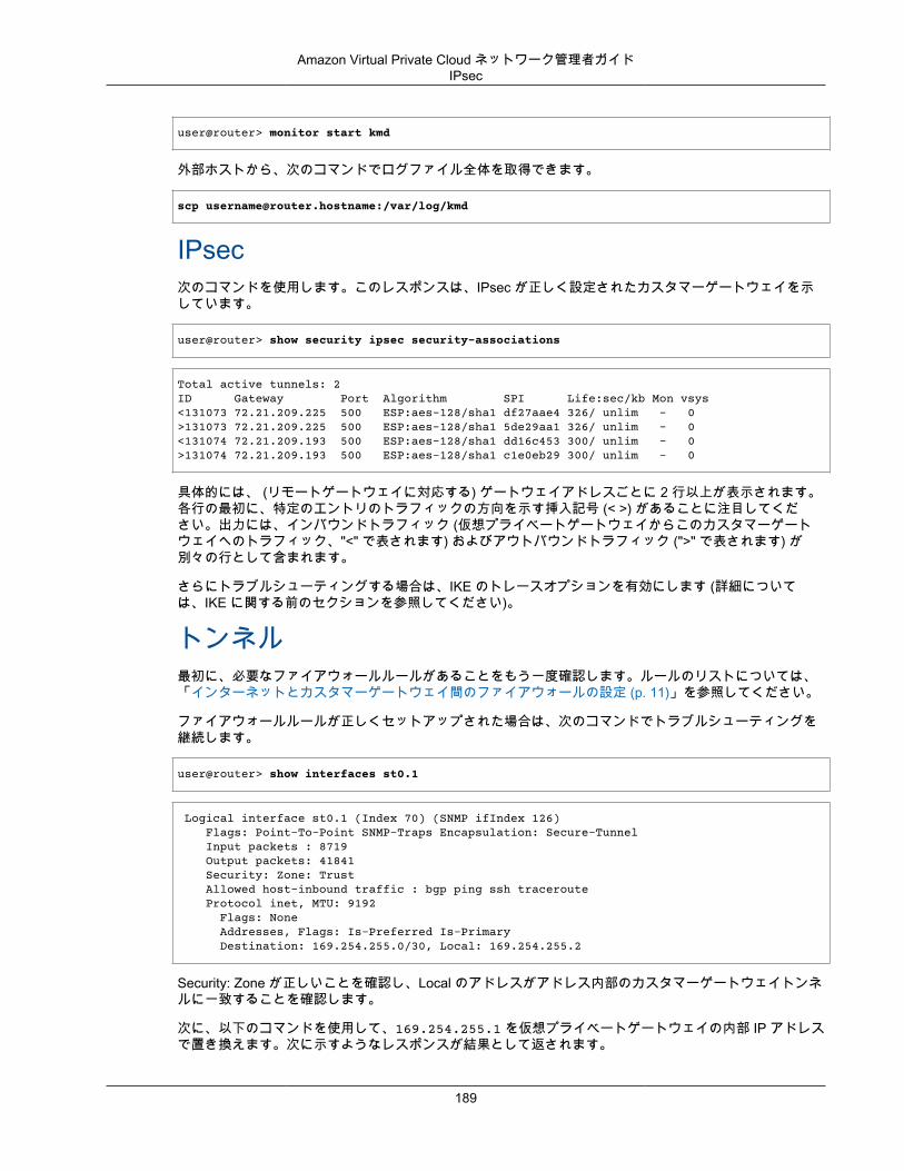
Amazon Virtual Private Cloud ネットワーク管理者ガイドIPsec
user@router> monitor start kmd
外部ホストから、次のコマンドでログファイル全体を取得できます。
scp [email protected]:/var/log/kmd
IPsec次のコマンドを使用します。このレスポンスは、IPsec が正しく設定されたカスタマーゲートウェイを示しています。
user@router> show security ipsec security-associations
Total active tunnels: 2ID Gateway Port Algorithm SPI Life:sec/kb Mon vsys<131073 72.21.209.225 500 ESP:aes-128/sha1 df27aae4 326/ unlim - 0>131073 72.21.209.225 500 ESP:aes-128/sha1 5de29aa1 326/ unlim - 0<131074 72.21.209.193 500 ESP:aes-128/sha1 dd16c453 300/ unlim - 0>131074 72.21.209.193 500 ESP:aes-128/sha1 c1e0eb29 300/ unlim - 0
具体的には、 (リモートゲートウェイに対応する) ゲートウェイアドレスごとに 2 行以上が表示されます。各行の最初に、特定のエントリのトラフィックの方向を示す挿入記号 (< >) があることに注目してください。出力には、インバウンドトラフィック (仮想プライベートゲートウェイからこのカスタマーゲートウェイへのトラフィック、"<" で表されます) およびアウトバウンドトラフィック (">" で表されます) が別々の行として含まれます。
さらにトラブルシューティングする場合は、IKE のトレースオプションを有効にします (詳細については、IKE に関する前のセクションを参照してください)。
トンネル最初に、必要なファイアウォールルールがあることをもう一度確認します。ルールのリストについては、「インターネットとカスタマーゲートウェイ間のファイアウォールの設定 (p. 11)」を参照してください。
ファイアウォールルールが正しくセットアップされた場合は、次のコマンドでトラブルシューティングを継続します。
user@router> show interfaces st0.1
Logical interface st0.1 (Index 70) (SNMP ifIndex 126) Flags: Point-To-Point SNMP-Traps Encapsulation: Secure-Tunnel Input packets : 8719 Output packets: 41841 Security: Zone: Trust Allowed host-inbound traffic : bgp ping ssh traceroute Protocol inet, MTU: 9192 Flags: None Addresses, Flags: Is-Preferred Is-Primary Destination: 169.254.255.0/30, Local: 169.254.255.2
Security: Zone が正しいことを確認し、Local のアドレスがアドレス内部のカスタマーゲートウェイトンネルに一致することを確認します。
次に、以下のコマンドを使用して、169.254.255.1 を仮想プライベートゲートウェイの内部 IP アドレスで置き換えます。次に示すようなレスポンスが結果として返されます。
189
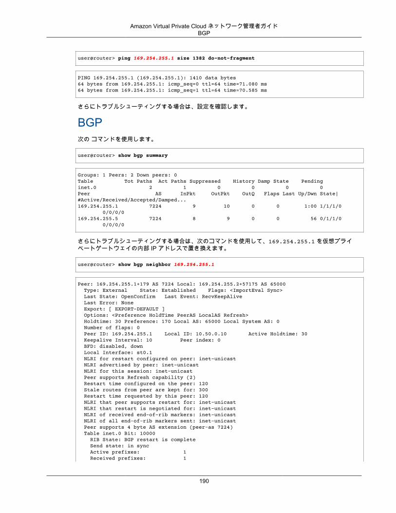
Amazon Virtual Private Cloud ネットワーク管理者ガイドBGP
user@router> ping 169.254.255.1 size 1382 do-not-fragment
PING 169.254.255.1 (169.254.255.1): 1410 data bytes64 bytes from 169.254.255.1: icmp_seq=0 ttl=64 time=71.080 ms64 bytes from 169.254.255.1: icmp_seq=1 ttl=64 time=70.585 ms
さらにトラブルシューティングする場合は、設定を確認します。
BGP次の コマンドを使用します。
user@router> show bgp summary
Groups: 1 Peers: 2 Down peers: 0Table Tot Paths Act Paths Suppressed History Damp State Pendinginet.0 2 1 0 0 0 0Peer AS InPkt OutPkt OutQ Flaps Last Up/Dwn State|#Active/Received/Accepted/Damped...169.254.255.1 7224 9 10 0 0 1:00 1/1/1/0 0/0/0/0169.254.255.5 7224 8 9 0 0 56 0/1/1/0 0/0/0/0
さらにトラブルシューティングする場合は、次のコマンドを使用して、169.254.255.1 を仮想プライベートゲートウェイの内部 IP アドレスで置き換えます。
user@router> show bgp neighbor 169.254.255.1
Peer: 169.254.255.1+179 AS 7224 Local: 169.254.255.2+57175 AS 65000 Type: External State: Established Flags: <ImportEval Sync> Last State: OpenConfirm Last Event: RecvKeepAlive Last Error: None Export: [ EXPORT-DEFAULT ] Options: <Preference HoldTime PeerAS LocalAS Refresh> Holdtime: 30 Preference: 170 Local AS: 65000 Local System AS: 0 Number of flaps: 0 Peer ID: 169.254.255.1 Local ID: 10.50.0.10 Active Holdtime: 30 Keepalive Interval: 10 Peer index: 0 BFD: disabled, down Local Interface: st0.1 NLRI for restart configured on peer: inet-unicast NLRI advertised by peer: inet-unicast NLRI for this session: inet-unicast Peer supports Refresh capability (2) Restart time configured on the peer: 120 Stale routes from peer are kept for: 300 Restart time requested by this peer: 120 NLRI that peer supports restart for: inet-unicast NLRI that restart is negotiated for: inet-unicast NLRI of received end-of-rib markers: inet-unicast NLRI of all end-of-rib markers sent: inet-unicast Peer supports 4 byte AS extension (peer-as 7224) Table inet.0 Bit: 10000 RIB State: BGP restart is complete Send state: in sync Active prefixes: 1 Received prefixes: 1
190
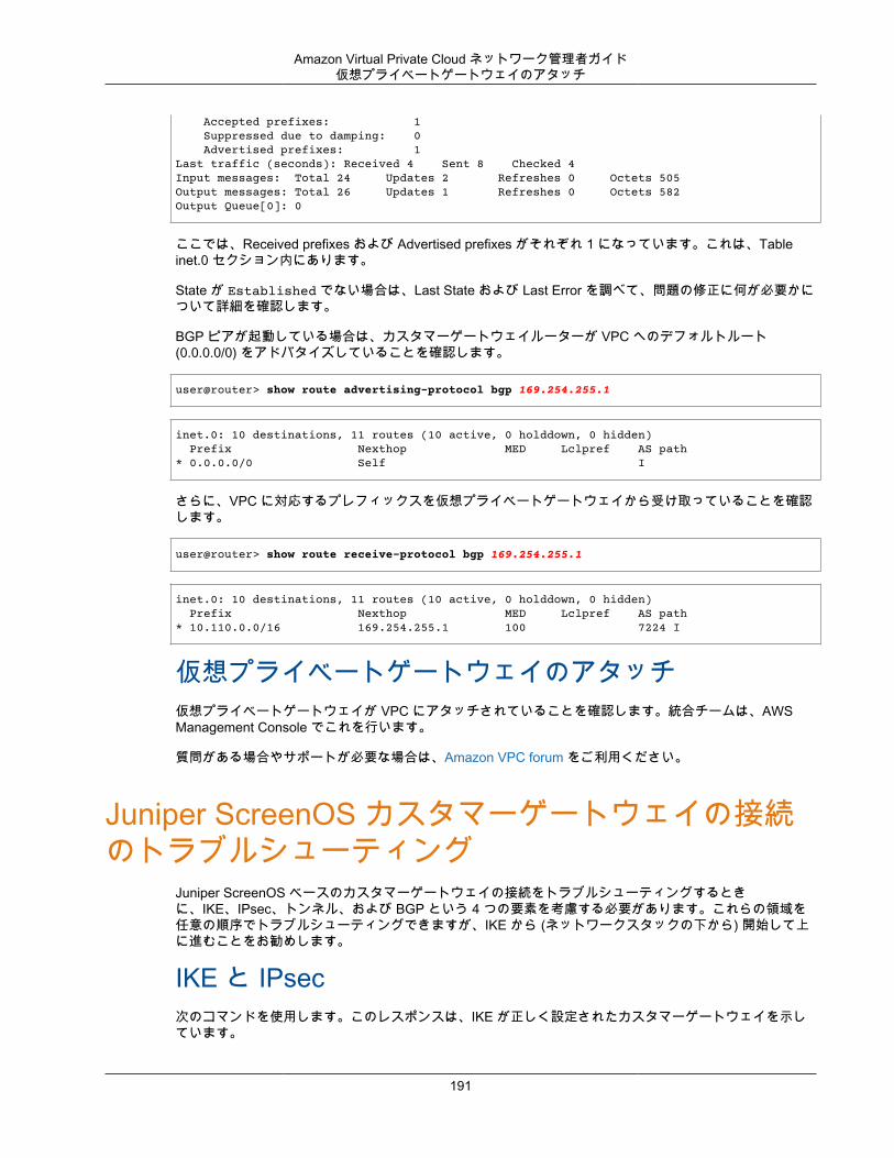
Amazon Virtual Private Cloud ネットワーク管理者ガイド仮想プライベートゲートウェイのアタッチ
Accepted prefixes: 1 Suppressed due to damping: 0 Advertised prefixes: 1Last traffic (seconds): Received 4 Sent 8 Checked 4 Input messages: Total 24 Updates 2 Refreshes 0 Octets 505Output messages: Total 26 Updates 1 Refreshes 0 Octets 582Output Queue[0]: 0
ここでは、Received prefixes および Advertised prefixes がそれぞれ 1 になっています。これは、Tableinet.0 セクション内にあります。
State が Established でない場合は、Last State および Last Error を調べて、問題の修正に何が必要かについて詳細を確認します。
BGP ピアが起動している場合は、カスタマーゲートウェイルーターが VPC へのデフォルトルート(0.0.0.0/0) をアドバタイズしていることを確認します。
user@router> show route advertising-protocol bgp 169.254.255.1
inet.0: 10 destinations, 11 routes (10 active, 0 holddown, 0 hidden) Prefix Nexthop MED Lclpref AS path* 0.0.0.0/0 Self I
さらに、VPC に対応するプレフィックスを仮想プライベートゲートウェイから受け取っていることを確認します。
user@router> show route receive-protocol bgp 169.254.255.1
inet.0: 10 destinations, 11 routes (10 active, 0 holddown, 0 hidden) Prefix Nexthop MED Lclpref AS path* 10.110.0.0/16 169.254.255.1 100 7224 I
仮想プライベートゲートウェイのアタッチ仮想プライベートゲートウェイが VPC にアタッチされていることを確認します。統合チームは、AWSManagement Console でこれを行います。
質問がある場合やサポートが必要な場合は、Amazon VPC forum をご利用ください。
Juniper ScreenOS カスタマーゲートウェイの接続のトラブルシューティング
Juniper ScreenOS ベースのカスタマーゲートウェイの接続をトラブルシューティングするときに、IKE、IPsec、トンネル、および BGP という 4 つの要素を考慮する必要があります。これらの領域を任意の順序でトラブルシューティングできますが、IKE から (ネットワークスタックの下から) 開始して上に進むことをお勧めします。
IKE と IPsec次のコマンドを使用します。このレスポンスは、IKE が正しく設定されたカスタマーゲートウェイを示しています。
191
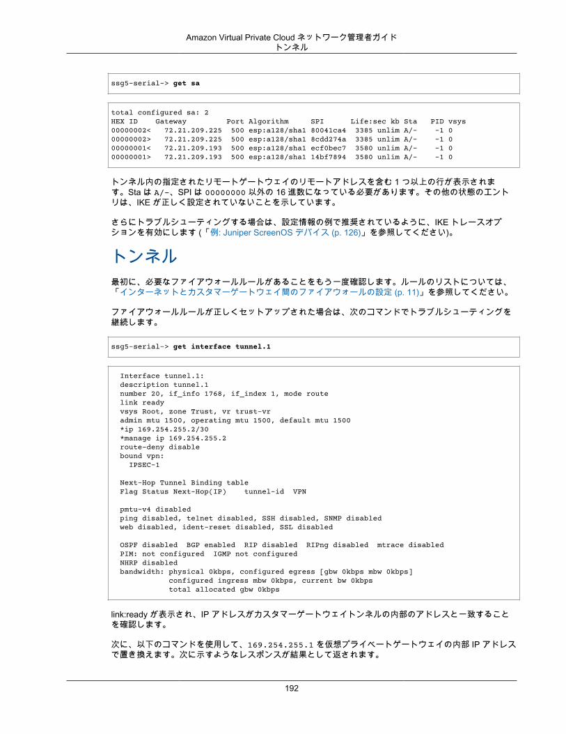
Amazon Virtual Private Cloud ネットワーク管理者ガイドトンネル
ssg5-serial-> get sa
total configured sa: 2HEX ID Gateway Port Algorithm SPI Life:sec kb Sta PID vsys00000002< 72.21.209.225 500 esp:a128/sha1 80041ca4 3385 unlim A/- -1 000000002> 72.21.209.225 500 esp:a128/sha1 8cdd274a 3385 unlim A/- -1 000000001< 72.21.209.193 500 esp:a128/sha1 ecf0bec7 3580 unlim A/- -1 000000001> 72.21.209.193 500 esp:a128/sha1 14bf7894 3580 unlim A/- -1 0
トンネル内の指定されたリモートゲートウェイのリモートアドレスを含む 1 つ以上の行が表示されます。Sta は A/-、SPI は 00000000 以外の 16 進数になっている必要があります。その他の状態のエントリは、IKE が正しく設定されていないことを示しています。
さらにトラブルシューティングする場合は、設定情報の例で推奨されているように、IKE トレースオプションを有効にします (「例: Juniper ScreenOS デバイス (p. 126)」を参照してください)。
トンネル最初に、必要なファイアウォールルールがあることをもう一度確認します。ルールのリストについては、「インターネットとカスタマーゲートウェイ間のファイアウォールの設定 (p. 11)」を参照してください。
ファイアウォールルールが正しくセットアップされた場合は、次のコマンドでトラブルシューティングを継続します。
ssg5-serial-> get interface tunnel.1
Interface tunnel.1: description tunnel.1 number 20, if_info 1768, if_index 1, mode route link ready vsys Root, zone Trust, vr trust-vr admin mtu 1500, operating mtu 1500, default mtu 1500 *ip 169.254.255.2/30 *manage ip 169.254.255.2 route-deny disable bound vpn: IPSEC-1
Next-Hop Tunnel Binding table Flag Status Next-Hop(IP) tunnel-id VPN
pmtu-v4 disabled ping disabled, telnet disabled, SSH disabled, SNMP disabled web disabled, ident-reset disabled, SSL disabled
OSPF disabled BGP enabled RIP disabled RIPng disabled mtrace disabled PIM: not configured IGMP not configured NHRP disabled bandwidth: physical 0kbps, configured egress [gbw 0kbps mbw 0kbps] configured ingress mbw 0kbps, current bw 0kbps total allocated gbw 0kbps
link:ready が表示され、IP アドレスがカスタマーゲートウェイトンネルの内部のアドレスと一致することを確認します。
次に、以下のコマンドを使用して、169.254.255.1 を仮想プライベートゲートウェイの内部 IP アドレスで置き換えます。次に示すようなレスポンスが結果として返されます。
192
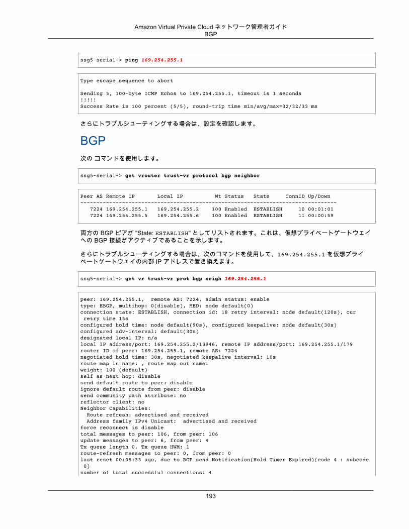
Amazon Virtual Private Cloud ネットワーク管理者ガイドBGP
ssg5-serial-> ping 169.254.255.1
Type escape sequence to abort
Sending 5, 100-byte ICMP Echos to 169.254.255.1, timeout is 1 seconds!!!!!Success Rate is 100 percent (5/5), round-trip time min/avg/max=32/32/33 ms
さらにトラブルシューティングする場合は、設定を確認します。
BGP次の コマンドを使用します。
ssg5-serial-> get vrouter trust-vr protocol bgp neighbor
Peer AS Remote IP Local IP Wt Status State ConnID Up/Down-------------------------------------------------------------------------------- 7224 169.254.255.1 169.254.255.2 100 Enabled ESTABLISH 10 00:01:01 7224 169.254.255.5 169.254.255.6 100 Enabled ESTABLISH 11 00:00:59
両方の BGP ピアが "State: ESTABLISH" としてリストされます。これは、仮想プライベートゲートウェイへの BGP 接続がアクティブであることを示します。
さらにトラブルシューティングする場合は、次のコマンドを使用して、169.254.255.1 を仮想プライベートゲートウェイの内部 IP アドレスで置き換えます。
ssg5-serial-> get vr trust-vr prot bgp neigh 169.254.255.1
peer: 169.254.255.1, remote AS: 7224, admin status: enabletype: EBGP, multihop: 0(disable), MED: node default(0)connection state: ESTABLISH, connection id: 18 retry interval: node default(120s), cur retry time 15sconfigured hold time: node default(90s), configured keepalive: node default(30s)configured adv-interval: default(30s)designated local IP: n/alocal IP address/port: 169.254.255.2/13946, remote IP address/port: 169.254.255.1/179router ID of peer: 169.254.255.1, remote AS: 7224negotiated hold time: 30s, negotiated keepalive interval: 10sroute map in name: , route map out name:weight: 100 (default)self as next hop: disablesend default route to peer: disableignore default route from peer: disablesend community path attribute: noreflector client: noNeighbor Capabilities: Route refresh: advertised and received Address family IPv4 Unicast: advertised and receivedforce reconnect is disabletotal messages to peer: 106, from peer: 106update messages to peer: 6, from peer: 4Tx queue length 0, Tx queue HWM: 1route-refresh messages to peer: 0, from peer: 0last reset 00:05:33 ago, due to BGP send Notification(Hold Timer Expired)(code 4 : subcode 0)number of total successful connections: 4
193
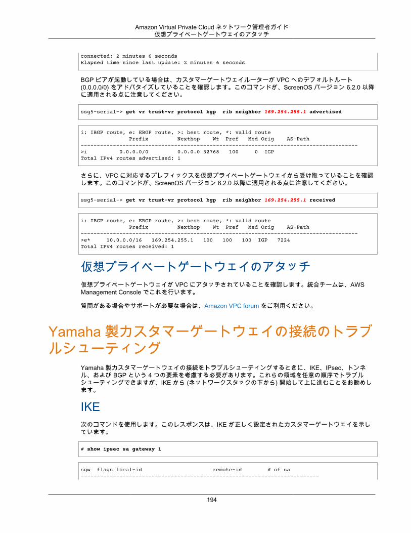
Amazon Virtual Private Cloud ネットワーク管理者ガイド仮想プライベートゲートウェイのアタッチ
connected: 2 minutes 6 secondsElapsed time since last update: 2 minutes 6 seconds
BGP ピアが起動している場合は、カスタマーゲートウェイルーターが VPC へのデフォルトルート(0.0.0.0/0) をアドバタイズしていることを確認します。このコマンドが、ScreenOS バージョン 6.2.0 以降に適用される点に注意してください。
ssg5-serial-> get vr trust-vr protocol bgp rib neighbor 169.254.255.1 advertised
i: IBGP route, e: EBGP route, >: best route, *: valid route Prefix Nexthop Wt Pref Med Orig AS-Path-------------------------------------------------------------------------------------->i 0.0.0.0/0 0.0.0.0 32768 100 0 IGPTotal IPv4 routes advertised: 1
さらに、VPC に対応するプレフィックスを仮想プライベートゲートウェイから受け取っていることを確認します。このコマンドが、ScreenOS バージョン 6.2.0 以降に適用される点に注意してください。
ssg5-serial-> get vr trust-vr protocol bgp rib neighbor 169.254.255.1 received
i: IBGP route, e: EBGP route, >: best route, *: valid route Prefix Nexthop Wt Pref Med Orig AS-Path-------------------------------------------------------------------------------------->e* 10.0.0.0/16 169.254.255.1 100 100 100 IGP 7224Total IPv4 routes received: 1
仮想プライベートゲートウェイのアタッチ仮想プライベートゲートウェイが VPC にアタッチされていることを確認します。統合チームは、AWSManagement Console でこれを行います。
質問がある場合やサポートが必要な場合は、Amazon VPC forum をご利用ください。
Yamaha 製カスタマーゲートウェイの接続のトラブルシューティング
Yamaha 製カスタマーゲートウェイの接続をトラブルシューティングするときに、IKE、IPsec、トンネル、および BGP という 4 つの要素を考慮する必要があります。これらの領域を任意の順序でトラブルシューティングできますが、IKE から (ネットワークスタックの下から) 開始して上に進むことをお勧めします。
IKE次のコマンドを使用します。このレスポンスは、IKE が正しく設定されたカスタマーゲートウェイを示しています。
# show ipsec sa gateway 1
sgw flags local-id remote-id # of sa--------------------------------------------------------------------------
194
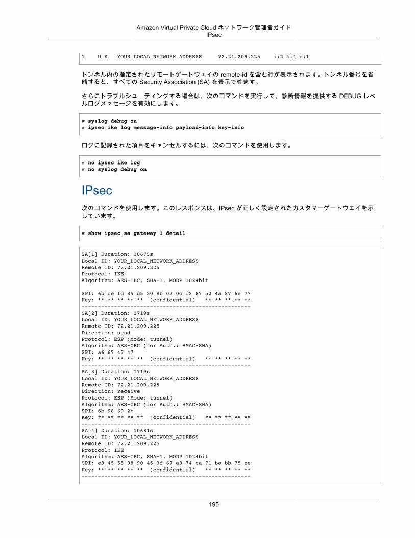
Amazon Virtual Private Cloud ネットワーク管理者ガイドIPsec
1 U K YOUR_LOCAL_NETWORK_ADDRESS 72.21.209.225 i:2 s:1 r:1
トンネル内の指定されたリモートゲートウェイの remote-id を含む行が表示されます。トンネル番号を省略すると、すべての Security Association (SA) を表示できます。
さらにトラブルシューティングする場合は、次のコマンドを実行して、診断情報を提供する DEBUG レベルログメッセージを有効にします。
# syslog debug on# ipsec ike log message-info payload-info key-info
ログに記録された項目をキャンセルするには、次のコマンドを使用します。
# no ipsec ike log# no syslog debug on
IPsec次のコマンドを使用します。このレスポンスは、IPsec が正しく設定されたカスタマーゲートウェイを示しています。
# show ipsec sa gateway 1 detail
SA[1] Duration: 10675sLocal ID: YOUR_LOCAL_NETWORK_ADDRESSRemote ID: 72.21.209.225Protocol: IKEAlgorithm: AES-CBC, SHA-1, MODP 1024bit
SPI: 6b ce fd 8a d5 30 9b 02 0c f3 87 52 4a 87 6e 77 Key: ** ** ** ** ** (confidential) ** ** ** ** **----------------------------------------------------SA[2] Duration: 1719sLocal ID: YOUR_LOCAL_NETWORK_ADDRESSRemote ID: 72.21.209.225Direction: sendProtocol: ESP (Mode: tunnel)Algorithm: AES-CBC (for Auth.: HMAC-SHA)SPI: a6 67 47 47 Key: ** ** ** ** ** (confidential) ** ** ** ** **----------------------------------------------------SA[3] Duration: 1719sLocal ID: YOUR_LOCAL_NETWORK_ADDRESSRemote ID: 72.21.209.225Direction: receiveProtocol: ESP (Mode: tunnel)Algorithm: AES-CBC (for Auth.: HMAC-SHA)SPI: 6b 98 69 2b Key: ** ** ** ** ** (confidential) ** ** ** ** **----------------------------------------------------SA[4] Duration: 10681sLocal ID: YOUR_LOCAL_NETWORK_ADDRESSRemote ID: 72.21.209.225Protocol: IKEAlgorithm: AES-CBC, SHA-1, MODP 1024bitSPI: e8 45 55 38 90 45 3f 67 a8 74 ca 71 ba bb 75 ee Key: ** ** ** ** ** (confidential) ** ** ** ** **----------------------------------------------------
195
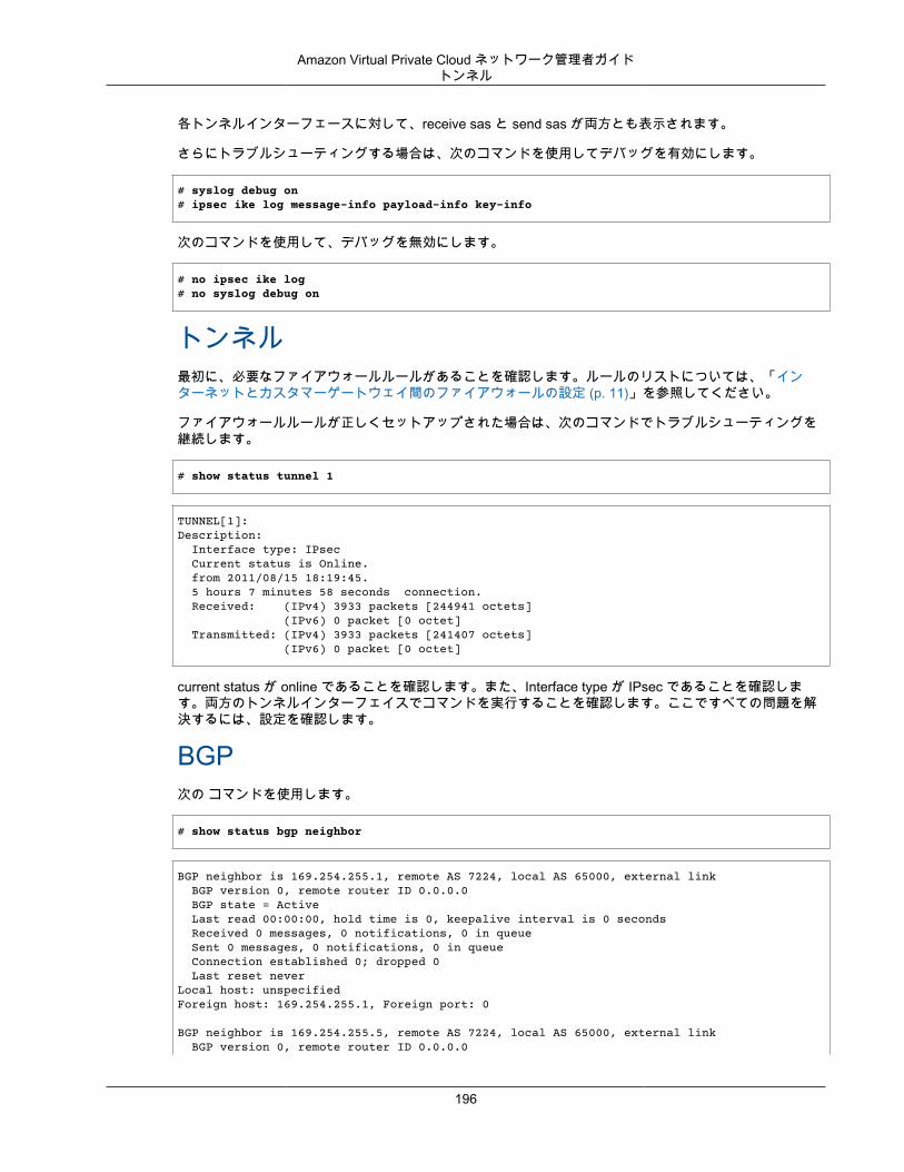
Amazon Virtual Private Cloud ネットワーク管理者ガイドトンネル
各トンネルインターフェースに対して、receive sas と send sas が両方とも表示されます。
さらにトラブルシューティングする場合は、次のコマンドを使用してデバッグを有効にします。
# syslog debug on# ipsec ike log message-info payload-info key-info
次のコマンドを使用して、デバッグを無効にします。
# no ipsec ike log# no syslog debug on
トンネル最初に、必要なファイアウォールルールがあることを確認します。ルールのリストについては、「インターネットとカスタマーゲートウェイ間のファイアウォールの設定 (p. 11)」を参照してください。
ファイアウォールルールが正しくセットアップされた場合は、次のコマンドでトラブルシューティングを継続します。
# show status tunnel 1
TUNNEL[1]: Description: Interface type: IPsec Current status is Online. from 2011/08/15 18:19:45. 5 hours 7 minutes 58 seconds connection. Received: (IPv4) 3933 packets [244941 octets] (IPv6) 0 packet [0 octet] Transmitted: (IPv4) 3933 packets [241407 octets] (IPv6) 0 packet [0 octet]
current status が online であることを確認します。また、Interface type が IPsec であることを確認します。両方のトンネルインターフェイスでコマンドを実行することを確認します。ここですべての問題を解決するには、設定を確認します。
BGP次の コマンドを使用します。
# show status bgp neighbor
BGP neighbor is 169.254.255.1, remote AS 7224, local AS 65000, external link BGP version 0, remote router ID 0.0.0.0 BGP state = Active Last read 00:00:00, hold time is 0, keepalive interval is 0 seconds Received 0 messages, 0 notifications, 0 in queue Sent 0 messages, 0 notifications, 0 in queue Connection established 0; dropped 0 Last reset neverLocal host: unspecifiedForeign host: 169.254.255.1, Foreign port: 0
BGP neighbor is 169.254.255.5, remote AS 7224, local AS 65000, external link BGP version 0, remote router ID 0.0.0.0
196
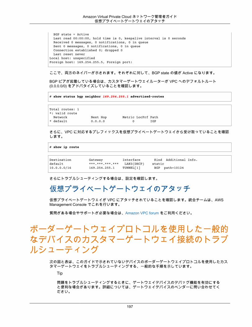
Amazon Virtual Private Cloud ネットワーク管理者ガイド仮想プライベートゲートウェイのアタッチ
BGP state = Active Last read 00:00:00, hold time is 0, keepalive interval is 0 seconds Received 0 messages, 0 notifications, 0 in queue Sent 0 messages, 0 notifications, 0 in queue Connection established 0; dropped 0 Last reset neverLocal host: unspecifiedForeign host: 169.254.255.5, Foreign port:
ここで、両方のネイバーが示されます。それぞれに対して、BGP state の値が Active になります。
BGP ピアが起動している場合は、カスタマーゲートウェイルーターが VPC へのデフォルトルート(0.0.0.0/0) をアドバタイズしていることを確認します。
# show status bgp neighbor 169.254.255.1 advertised-routes
Total routes: 1*: valid route Network Next Hop Metric LocPrf Path* default 0.0.0.0 0 IGP
さらに、VPC に対応するプレフィックスを仮想プライベートゲートウェイから受け取っていることを確認します。
# show ip route
Destination Gateway Interface Kind Additional Info.default ***.***.***.*** LAN3(DHCP) static 10.0.0.0/16 169.254.255.1 TUNNEL[1] BGP path=10124
さらにトラブルシューティングする場合は、設定を確認します。
仮想プライベートゲートウェイのアタッチ仮想プライベートゲートウェイが VPC にアタッチされていることを確認します。統合チームは、AWSManagement Console でこれを行います。
質問がある場合やサポートが必要な場合は、Amazon VPC forum をご利用ください。
ボーダーゲートウェイプロトコルを使用した一般的なデバイスのカスタマーゲートウェイ接続のトラブルシューティング
次の図と表は、このガイドで示されていないデバイスのボーダーゲートウェイプロトコルを使用したカスタマーゲートウェイをトラブルシューティングする、一般的な手順を示しています。
Tip
問題をトラブルシューティングするときに、ゲートウェイデバイスのデバッグ機能を有効にすると便利な場合があります。詳細については、ゲートウェイデバイスのベンダーに問い合わせてください。
197
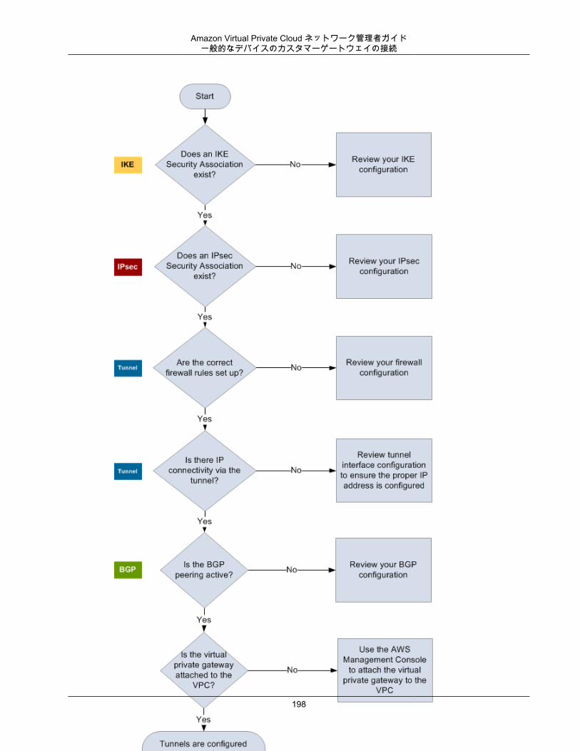
Amazon Virtual Private Cloud ネットワーク管理者ガイド一般的なデバイスのカスタマーゲートウェイの接続
198
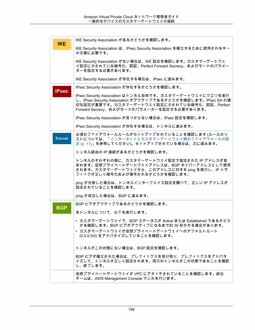
Amazon Virtual Private Cloud ネットワーク管理者ガイド一般的なデバイスのカスタマーゲートウェイの接続
IKE Security Association があるかどうかを確認します。
IKE Security Association は、IPsec Security Association を確立するために使用されるキーの交換に必要です。
IKE Security Association がない場合は、IKE 設定を確認します。カスタマーゲートウェイ設定に示されている暗号化、認証、Perfect Forward Secrecy、およびモードのパラメーターを設定する必要があります。
IKE Security Association が存在する場合は、IPsec に進みます。
IPsec Security Association が存在するかどうかを確認します。
IPsec Security Association はトンネル自体です。カスタマーゲートウェイにクエリを実行し、IPsec Security Association がアクティブであるかどうかを確認します。IPsec SA の適切な設定が重要です。カスタマーゲートウェイ設定に示されている暗号化、認証、PerfectForward Secrecy、およびモードのパラメーターを設定する必要があります。
IPsec Security Association が見つからない場合は、IPsec 設定を確認します。
IPsec Security Association が存在する場合は、トンネルに進みます。
必須のファイアウォールルールがセットアップされていることを確認します (ルールのリストについては、「インターネットとカスタマーゲートウェイ間のファイアウォールの設定 (p. 11)」を参照してください)。セットアップされている場合は、次に進みます。
トンネル経由の IP 接続があるかどうかを確認します。
トンネルのそれぞれの側に、カスタマーゲートウェイ設定で指定された IP アドレスが含まれます。仮想プライベートゲートウェイアドレスは、BGP ネイバーアドレスとして使用されます。カスタマーゲートウェイから、このアドレスに対する ping を実行し、IP トラフィックが正しく暗号化および復号されるかどうかを確認します。
ping が失敗した場合は、トンネルインターフェイス設定を調べて、正しい IP アドレスが設定されていることを確認します。
ping が成功した場合は、BGP に進みます。
BGP ピアがアクティブであるかどうかを確認します。
各トンネルについて、以下を実行します。
• カスタマーゲートウェイで、BGP ステータスが Active または Established であるかどうかを確認します。BGP ピアがアクティブになるまで約 30 秒かかる場合があります。
• カスタマーゲートウェイが仮想プライベートゲートウェイへのデフォルトルート(0.0.0.0/0) をアドバタイズしていることを確認します。
トンネルがこの状態にない場合は、BGP 設定を確認します。
BGP ピアが確立された場合は、プレフィックスを受け取り、プレフィックスをアドバタイズして、トンネルが正しく設定されます。両方のトンネルがこの状態であることを確認し、終了します。
仮想プライベートゲートウェイが VPC にアタッチされていることを確認します。統合チームは、AWS Management Console でこれを行います。
199
Amazon Virtual Private Cloud ネットワーク管理者ガイド一般的なデバイスのカスタマーゲートウェイ接続 (BGP なし)
すべてのカスタマーゲートウェイに適用できる一般的なテストの手順については、「カスタマーゲートウェイ設定をテストする方法 (p. 166)」を参照してください。
質問がある場合やサポートが必要な場合は、Amazon VPC forum をご利用ください。
ボーダーゲートウェイプロトコル接続を使用しない一般的なデバイスのカスタマーゲートウェイのトラブルシューティング
次の図と表は、ボーダーゲートウェイプロトコルを使用しないカスタマーゲートウェイデバイスをトラブルシューティングする、一般的な手順を示しています。
Tip
問題をトラブルシューティングするときに、ゲートウェイデバイスのデバッグ機能を有効にすると便利な場合があります。詳細については、ゲートウェイデバイスのベンダーに問い合わせてください。
200
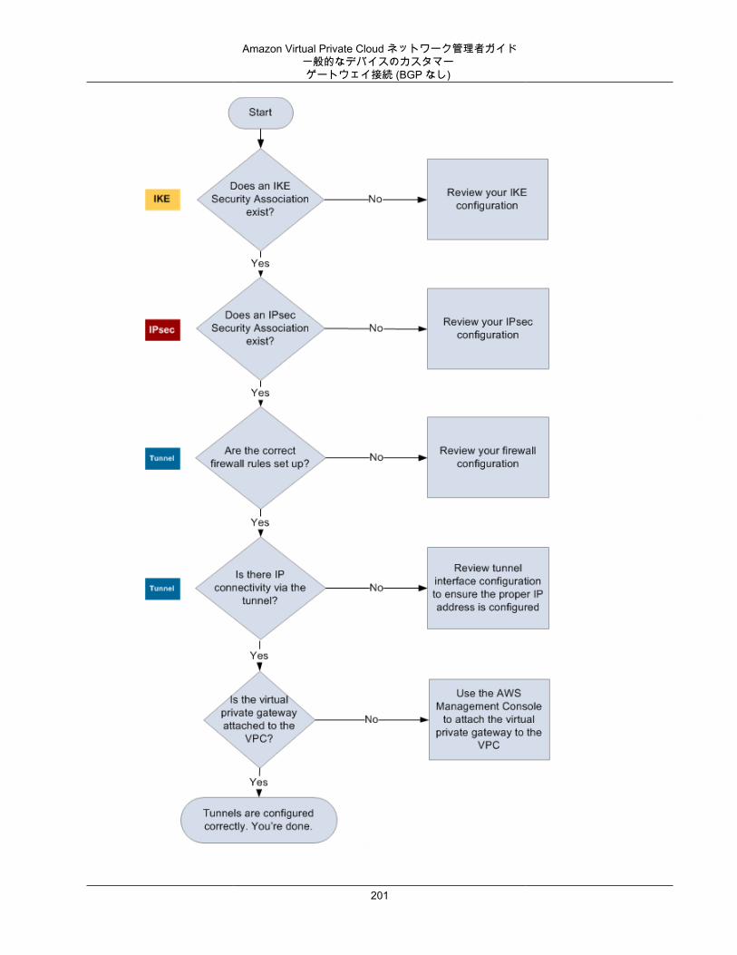
Amazon Virtual Private Cloud ネットワーク管理者ガイド一般的なデバイスのカスタマーゲートウェイ接続 (BGP なし)
201
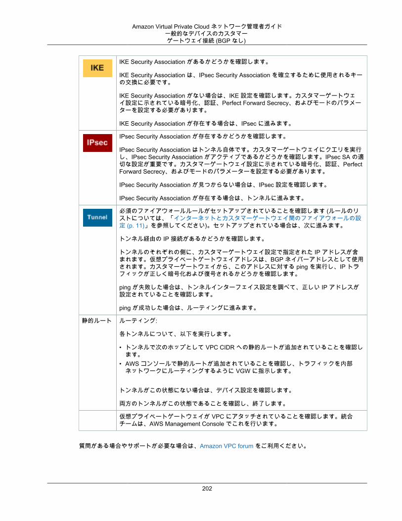
Amazon Virtual Private Cloud ネットワーク管理者ガイド一般的なデバイスのカスタマーゲートウェイ接続 (BGP なし)
IKE Security Association があるかどうかを確認します。
IKE Security Association は、IPsec Security Association を確立するために使用されるキーの交換に必要です。
IKE Security Association がない場合は、IKE 設定を確認します。カスタマーゲートウェイ設定に示されている暗号化、認証、Perfect Forward Secrecy、およびモードのパラメーターを設定する必要があります。
IKE Security Association が存在する場合は、IPsec に進みます。
IPsec Security Association が存在するかどうかを確認します。
IPsec Security Association はトンネル自体です。カスタマーゲートウェイにクエリを実行し、IPsec Security Association がアクティブであるかどうかを確認します。IPsec SA の適切な設定が重要です。カスタマーゲートウェイ設定に示されている暗号化、認証、PerfectForward Secrecy、およびモードのパラメーターを設定する必要があります。
IPsec Security Association が見つからない場合は、IPsec 設定を確認します。
IPsec Security Association が存在する場合は、トンネルに進みます。
必須のファイアウォールルールがセットアップされていることを確認します (ルールのリストについては、「インターネットとカスタマーゲートウェイ間のファイアウォールの設定 (p. 11)」を参照してください)。セットアップされている場合は、次に進みます。
トンネル経由の IP 接続があるかどうかを確認します。
トンネルのそれぞれの側に、カスタマーゲートウェイ設定で指定された IP アドレスが含まれます。仮想プライベートゲートウェイアドレスは、BGP ネイバーアドレスとして使用されます。カスタマーゲートウェイから、このアドレスに対する ping を実行し、IP トラフィックが正しく暗号化および復号されるかどうかを確認します。
ping が失敗した場合は、トンネルインターフェイス設定を調べて、正しい IP アドレスが設定されていることを確認します。
ping が成功した場合は、ルーティングに進みます。
静的ルート ルーティング:
各トンネルについて、以下を実行します。
• トンネルで次のホップとして VPC CIDR への静的ルートが追加されていることを確認します。
• AWS コンソールで静的ルートが追加されていることを確認し、トラフィックを内部ネットワークにルーティングするように VGW に指示します。
トンネルがこの状態にない場合は、デバイス設定を確認します。
両方のトンネルがこの状態であることを確認し、終了します。
仮想プライベートゲートウェイが VPC にアタッチされていることを確認します。統合チームは、AWS Management Console でこれを行います。
質問がある場合やサポートが必要な場合は、Amazon VPC forum をご利用ください。
202
Amazon Virtual Private Cloud ネットワーク管理者ガイドWindows Server の設定
Windows Server 2008 R2 のカスタマーゲートウェイとしての設定
Windows Server 2008 R2 を VPC 用のカスタマーゲートウェイとして設定できます。Windows Server2008 R2 を VPC 内の EC2 インスタンスで実行しているか独自のサーバーで実行しているかに関わらず、次のプロセスを使用します。
トピック• Windows Server の設定 (p. 203)• ステップ 1: VPN 接続を作成し、VPC を設定する (p. 204)• ステップ 2: VPN 接続の設定ファイルをダウンロードする (p. 205)• ステップ 3: Windows Server を設定する (p. 206)• ステップ 4: VPN トンネルを設定する (p. 209)• ステップ 5: 停止しているゲートウェイを検出する (p. 215)• ステップ 6: VPN 接続をテストする (p. 215)
Windows Server の設定Windows Server をカスタマーゲートウェイとして設定するには、Windows Server 2008 R2 を独自のネットワーク上に配置するか、VPC の EC2 インスタンス上に配置します。Windows AMI から起動した EC2インスタンスを使用している場合は、以下の作業を行います。
• インスタンスの送信元/送信先チェックを無効にします。1. https://console.aws.amazon.com/ec2/) にある Amazon EC2 コンソールを開きます。2. Windows Server インスタンスを選択して、[Actions] を選択し、次に [Networking] を選択して、
[Change Source/Dest.Check] を選択します。[Yes, Disable] を選択します。• 他のインスタンスからトラフィックをルーティングできるように、アダプタの設定を更新します。
1. Windows インスタンスに接続します。詳細については、「Windows インスタンスへの接続」を参照してください。
2. [コントロールパネル] を開き、[デバイスマネージャー] を起動します。3. [ネットワークアダプター] ノードを展開します。4. Citrix または AWS PV network adapter を右クリックし、[Properties] をクリックします。5. [詳細設定] タブで、[IPv4 Checksum Offload]、[TCP Checksum Offload (IPv4)]、および [UDP
Checksum Offload (IPv4)] の各プロパティを無効にし、[OK] を選択します。• Elastic IP アドレスとインスタンスを関連付けます。
1. https://console.aws.amazon.com/ec2/) にある Amazon EC2 コンソールを開きます。2. ナビゲーションペインで [Elastic IP] を選択します。[Allocate new address] を選択します。3. Elastic IP アドレスを選択し、[Actions]、[Associate Address] の順に選択します。4. [Instance] で、Windows Server インスタンスを選択します。[Associate] を選択します。
このアドレスは書き留めておきます。VPC でカスタマーゲートウェイを作成する際に必要になります。• インスタンスのセキュリティグループのルールでアウトバウンドの IPsec トラフィックが許可されてい
ることを確認します。デフォルトでは、セキュリティグループはすべてのアウトバウンドトラフィックを許可します。ただし、セキュリティグループのアウトバウンドルールが元の状態から変更されている場合、IPsec トラフィック用にアウトバウンドのカスタムプロトコルルール (IP プロトコル 50、IP プロトコル 51、UDP 500) を作成する必要があります。
203
Amazon Virtual Private Cloud ネットワーク管理者ガイドステップ 1: VPN 接続を作成し、VPC を設定する
Windows Server が存在するネットワークの CIDR 範囲 (たとえば、172.31.0.0/16) をメモしておきます。
ステップ 1: VPN 接続を作成し、VPC を設定するVPC から VPN 接続を作成するには、まず仮想プライベートゲートウェイを作成し、それを VPC にアタッチする必要があります。その後、VPN 接続を作成し、VPC を設定することができます。Windows Serverが存在するネットワークの CIDR 範囲 (たとえば、172.31.0.0/16) も指定する必要があります。
仮想プライベートゲートウェイを作成するには
1. https://console.aws.amazon.com/vpc/にある Amazon VPC コンソールを開きます。2. ナビゲーションペインで [Virtual Private Gateways] を選択してから、[Create Virtual Private Gateway]
をクリックします。3. 任意で仮想プライベートゲートウェイの名前を入力し、[Yes, Create] を選択します。4. 作成した仮想プライベートゲートウェイを選択して、[Attach to VPC] を選択します。5. [Attach to VPC] ダイアログボックスのリストから VPC を選択してから、[Yes, Attach] を選択しま
す。
VPN 接続を作成するには
1. https://console.aws.amazon.com/vpc/にある Amazon VPC コンソールを開きます。2. ナビゲーションペインで [VPN 接続] を選択し、[VPN 接続の作成] を選択します。3. リストから仮想プライベートゲートウェイを選択します。4. [Customer Gateway] で、[New] を選択します。[IP address] で、Windows サーバーのパブリック IP
アドレスを指定します。
Note
この IP アドレスは静的である必要があります。また、ネットワークアドレス変換 (NAT) を実行するデバイスの背後のアドレスを使用することができます。NAT トラバーサル (NAT-T)を正しく機能させるには、UDP ポート 4500 のブロックを解除するようにファイアウォールのルールを調整する必要があります。カスタマーゲートウェイが EC2 Windows Server インスタンスである場合は、その Elastic IP アドレスを使用します。
5. ルーティングオプションとして [静的] を選択し、ネットワークの [静的 IP プレフィックス] の値をCIDR 表記で入力して、[作成] を選択します。
VPC を設定するには
• Windows サーバーと通信するインスタンスを起動するためのプライベートサブネットを VPC で作成します (まだ、ない場合)。詳細については、「VPC にサブネットを追加する」を参照してください。
Note
プライベートサブネットは、インターネットゲートウェイへのルートがないサブネットです。このサブネットのルーティングについては、次の項目で説明します。
• VPN 接続のルートテーブルを更新します。• 仮想プライベートゲートウェイをターゲットに指定し、Windows Server のネットワーク (CIDR 範囲)
を宛先に指定して、プライベートサブネットのルートテーブルにルートを追加します。• 仮想プライベートゲートウェイのルート伝達を有効にします。詳細については、Amazon VPC ユー
ザーガイド の「ルートテーブル」を参照してください。• VPC とネットワーク間の通信を許可する、インスタンスのセキュリティグループ設定を作成します。
204
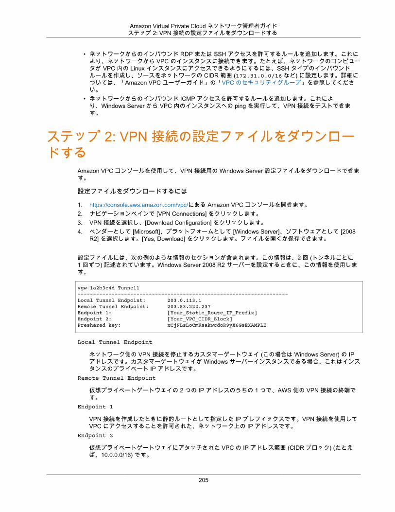
Amazon Virtual Private Cloud ネットワーク管理者ガイドステップ 2: VPN 接続の設定ファイルをダウンロードする
• ネットワークからのインバウンド RDP または SSH アクセスを許可するルールを追加します。これにより、ネットワークから VPC のインスタンスに接続できます。たとえば、ネットワークのコンピュータが VPC 内の Linux インスタンスにアクセスできるようにするには、SSH タイプのインバウンドルールを作成し、ソースをネットワークの CIDR 範囲 (172.31.0.0/16 など) に設定します。詳細については、「Amazon VPC ユーザーガイド」の「VPC のセキュリティグループ」を参照してください。
• ネットワークからのインバウンド ICMP アクセスを許可するルールを追加します。これにより、Windows Server から VPC 内のインスタンスへの ping を実行して、VPN 接続をテストできます。
ステップ 2: VPN 接続の設定ファイルをダウンロードする
Amazon VPC コンソールを使用して、VPN 接続用の Windows Server 設定ファイルをダウンロードできます。
設定ファイルをダウンロードするには
1. https://console.aws.amazon.com/vpc/にある Amazon VPC コンソールを開きます。2. ナビゲーションペインで [VPN Connections] をクリックします。3. VPN 接続を選択し、[Download Configuration] をクリックします。4. ベンダーとして [Microsoft]、プラットフォームとして [Windows Server]、ソフトウェアとして [2008
R2] を選択します。[Yes, Download] をクリックします。ファイルを開くか保存できます。
設定ファイルには、次の例のような情報のセクションが含まれます。この情報は、2 回 (トンネルごとに1 回ずつ) 記述されています。Windows Server 2008 R2 サーバーを設定するときに、この情報を使用します。
vgw-1a2b3c4d Tunnel1-------------------------------------------------------------------- Local Tunnel Endpoint: 203.0.113.1Remote Tunnel Endpoint: 203.83.222.237Endpoint 1: [Your_Static_Route_IP_Prefix]Endpoint 2: [Your_VPC_CIDR_Block]Preshared key: xCjNLsLoCmKsakwcdoR9yX6GsEXAMPLE
Local Tunnel Endpoint
ネットワーク側の VPN 接続を停止するカスタマーゲートウェイ (この場合は Windows Server) の IPアドレスです。カスタマーゲートウェイが Windows サーバーインスタンスである場合、これはインスタンスのプライベート IP アドレスです。
Remote Tunnel Endpoint
仮想プライベートゲートウェイの 2 つの IP アドレスのうちの 1 つで、AWS 側の VPN 接続の終端です。
Endpoint 1
VPN 接続を作成したときに静的ルートとして指定した IP プレフィックスです。VPN 接続を使用してVPC にアクセスすることを許可された、ネットワーク上の IP アドレスです。
Endpoint 2
仮想プライベートゲートウェイにアタッチされた VPC の IP アドレス範囲 (CIDR ブロック) (たとえば、10.0.0.0/16) です。
205
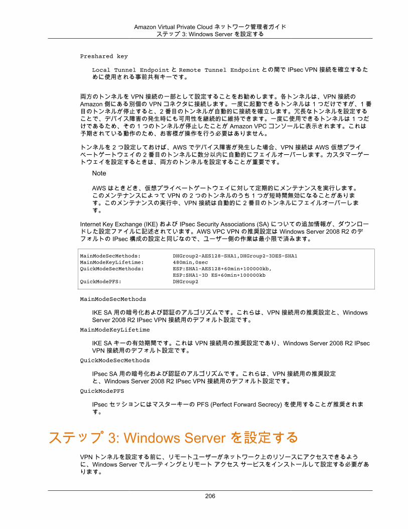
Amazon Virtual Private Cloud ネットワーク管理者ガイドステップ 3: Windows Server を設定する
Preshared key
Local Tunnel Endpoint と Remote Tunnel Endpoint との間で IPsec VPN 接続を確立するために使用される事前共有キーです。
両方のトンネルを VPN 接続の一部として設定することをお勧めします。各トンネルは、VPN 接続のAmazon 側にある別個の VPN コネクタに接続します。一度に起動できるトンネルは 1 つだけですが、1 番目のトンネルが停止すると、2 番目のトンネルが自動的に接続を確立します。冗長なトンネルを設定することで、デバイス障害の発生時にも可用性を継続的に維持できます。一度に使用できるトンネルは 1 つだけであるため、その 1 つのトンネルが停止したことが Amazon VPC コンソールに表示されます。これは予期されている動作のため、お客様が操作を行う必要はありません。
トンネルを 2 つ設定しておけば、AWS でデバイス障害が発生した場合、VPN 接続は AWS 仮想プライベートゲートウェイの 2 番目のトンネルに数分以内に自動的にフェイルオーバーします。カスタマーゲートウェイを設定するときは、両方のトンネルを設定することが重要です。
Note
AWS はときどき、仮想プライベートゲートウェイに対して定期的にメンテナンスを実行します。このメンテナンスによって VPN の 2 つのトンネルのうち 1 つが短時間無効になることがあります。このメンテナンスの実行中、VPN 接続は自動的に 2 番目のトンネルにフェイルオーバーします。
Internet Key Exchange (IKE) および IPsec Security Associations (SA) についての追加情報が、ダウンロードした設定ファイルに記述されています。AWS VPC VPN の推奨設定は Windows Server 2008 R2 のデフォルトの IPsec 構成の設定と同じなので、ユーザー側の作業は最小限で済みます。
MainModeSecMethods: DHGroup2-AES128-SHA1,DHGroup2-3DES-SHA1 MainModeKeyLifetime: 480min,0sec QuickModeSecMethods: ESP:SHA1-AES128+60min+100000kb, ESP:SHA1-3D ES+60min+100000kb QuickModePFS: DHGroup2
MainModeSecMethods
IKE SA 用の暗号化および認証のアルゴリズムです。これらは、VPN 接続用の推奨設定と、WindowsServer 2008 R2 IPsec VPN 接続用のデフォルト設定です。
MainModeKeyLifetime
IKE SA キーの有効期間です。これは VPN 接続用の推奨設定であり、Windows Server 2008 R2 IPsecVPN 接続用のデフォルト設定です。
QuickModeSecMethods
IPsec SA 用の暗号化および認証のアルゴリズムです。これらは、VPN 接続用の推奨設定と、Windows Server 2008 R2 IPsec VPN 接続用のデフォルト設定です。
QuickModePFS
IPsec セッションにはマスターキーの PFS (Perfect Forward Secrecy) を使用することが推奨されます。
ステップ 3: Windows Server を設定するVPN トンネルを設定する前に、リモートユーザーがネットワーク上のリソースにアクセスできるように、Windows Server でルーティングとリモート アクセス サービスをインストールして設定する必要があります。
206
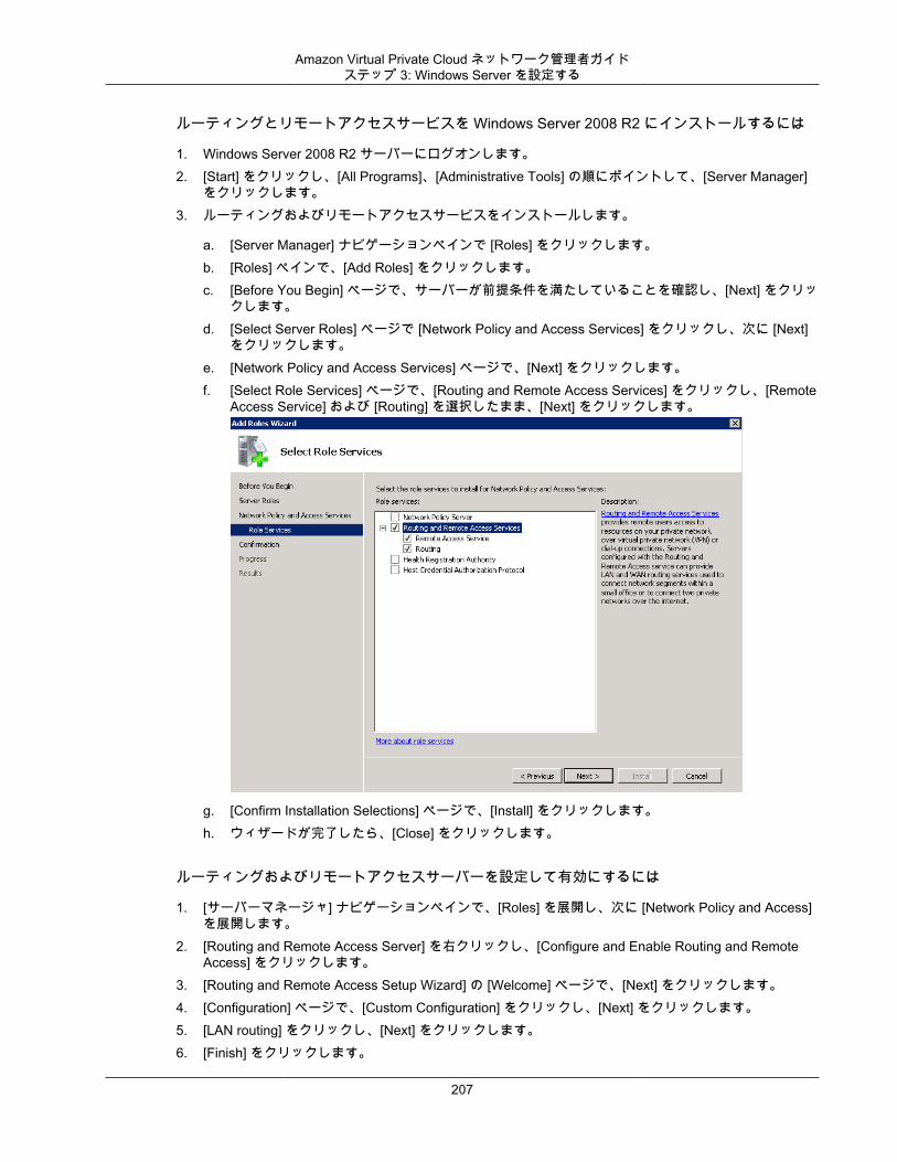
Amazon Virtual Private Cloud ネットワーク管理者ガイドステップ 3: Windows Server を設定する
ルーティングとリモートアクセスサービスを Windows Server 2008 R2 にインストールするには
1. Windows Server 2008 R2 サーバーにログオンします。2. [Start] をクリックし、[All Programs]、[Administrative Tools] の順にポイントして、[Server Manager]
をクリックします。3. ルーティングおよびリモートアクセスサービスをインストールします。
a. [Server Manager] ナビゲーションペインで [Roles] をクリックします。b. [Roles] ペインで、[Add Roles] をクリックします。c. [Before You Begin] ページで、サーバーが前提条件を満たしていることを確認し、[Next] をクリッ
クします。d. [Select Server Roles] ページで [Network Policy and Access Services] をクリックし、次に [Next]
をクリックします。e. [Network Policy and Access Services] ページで、[Next] をクリックします。f. [Select Role Services] ページで、[Routing and Remote Access Services] をクリックし、[Remote
Access Service] および [Routing] を選択したまま、[Next] をクリックします。
g. [Confirm Installation Selections] ページで、[Install] をクリックします。h. ウィザードが完了したら、[Close] をクリックします。
ルーティングおよびリモートアクセスサーバーを設定して有効にするには
1. [サーバーマネージャ] ナビゲーションペインで、[Roles] を展開し、次に [Network Policy and Access]を展開します。
2. [Routing and Remote Access Server] を右クリックし、[Configure and Enable Routing and RemoteAccess] をクリックします。
3. [Routing and Remote Access Setup Wizard] の [Welcome] ページで、[Next] をクリックします。4. [Configuration] ページで、[Custom Configuration] をクリックし、[Next] をクリックします。5. [LAN routing] をクリックし、[Next] をクリックします。6. [Finish] をクリックします。
207

Amazon Virtual Private Cloud ネットワーク管理者ガイドステップ 3: Windows Server を設定する
7. [Routing and Remote Access] ダイアログボックスにメッセージが表示されたら、[Start service] をクリックします。
208
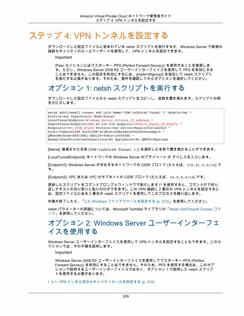
Amazon Virtual Private Cloud ネットワーク管理者ガイドステップ 4: VPN トンネルを設定する
ステップ 4: VPN トンネルを設定するダウンロードした設定ファイルに含まれている netsh スクリプトを実行するか、Windows Server で新規の接続セキュリティのルールウィザードを使用して、VPN トンネルを設定できます。
Important
IPsec セッションにはマスターキー PFS (Perfect Forward Secrecy) を使用することを推奨します。ただし、Windows Server 2008 R2 ユーザーインターフェイスを使用して PFS を有効にすることはできません。この設定を有効にするには、qmpfs=dhgroup2 を指定して netsh スクリプトを実行する必要があります。そのため、要件を確認してからオプションを選択してください。
オプション 1: netsh スクリプトを実行するダウンロードした設定ファイルから netsh スクリプトをコピーし、変数を置き換えます。スクリプトの例を次に示します。
netsh advfirewall consec add rule Name="VGW-1a2b3c4d Tunnel 1" Enable=Yes ^Profile=any Type=Static Mode=Tunnel LocalTunnelEndpoint=Windows_Server_Private_IP_address ^RemoteTunnelEndpoint=203.83.222.236 Endpoint1=Static_Route_IP_Prefix ^Endpoint2=VPC_CIDR_Block Protocol=Any Action=RequireInClearOut ^Auth1=ComputerPSK Auth1PSK=xCjNLsLoCmKsakwcdoR9yX6Gsexample ^QMSecMethods=ESP:SHA1-AES128+60min+100000kb ^ExemptIPsecProtectedConnections=No ApplyAuthz=No QMPFS=dhgroup2
[Name]: 推奨された名前 (VGW-1a2b3c4d Tunnel 1)) を選択した名前で置き換えることができます。
[LocalTunnelEndpoint]: ネットワークの Windows Server のプライベート IP アドレスを入力します。
[Endpoint1]: Windows Server が存在するネットワークの CIDR ブロック (たとえば、172.31.0.0/16) です。
[Endpoint2]: VPC または VPC のサブネットの CIDR ブロック (たとえば、10.0.0.0/16) です。
更新したスクリプトをコマンドプロンプトウィンドウで実行します (^ を使用すると、コマンド行で折り返しテキストの切り取りと貼り付けができます)。この VPN 接続に 2 番目の VPN トンネルを設定するには、設定ファイルにある 2 番目の netsh スクリプトを使用してこのプロセスを繰り返します。
作業が終了したら、「2.4: Windows ファイアウォールを設定する (p. 213)」を参照してください。
netsh パラメーターの詳細については、Microsoft TechNet ライブラリの「Netsh AdvFirewall Consec コマンド」を参照してください。
オプション 2: Windows Server ユーザーインターフェイスを使用するWindows Server ユーザーインターフェイスを使用して VPN トンネルを設定することもできます。このセクションでは、その手順を説明します。
Important
Windows Server 2008 R2 ユーザーインターフェイスを使用してマスターキー PFS (PerfectForward Secrecy) を有効にすることはできません。そのため、PFS を使用する場合は、このオプションで説明するユーザーインターフェイスではなく、オプション 1 で説明した netsh スクリプトを使用する必要があります。
• 2.1: VPN トンネル用のセキュリティルールを設定する (p. 210)
209
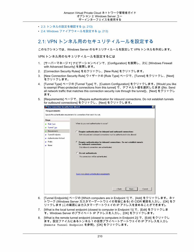
Amazon Virtual Private Cloud ネットワーク管理者ガイドオプション 2: Windows Server ユー
ザーインターフェイスを使用する
• 2.3: トンネルの設定を確認する (p. 213)• 2.4: Windows ファイアウォールを設定する (p. 213)
2.1: VPN トンネル用のセキュリティルールを設定するこのセクションでは、Windows Server のセキュリティルールを設定して VPN トンネルを作成します。
VPN トンネル用のセキュリティルールを設定するには
1. [サーバーマネージャ] ナビゲーションペインで、[Configuration] を展開し、次に [Windows Firewallwith Advanced Security] を展開します。
2. [Connection Security Rules] を右クリックし、[New Rule] をクリックします。3. [New Connection Security Rule] ウィザードの [Rule Type] ページで、[Tunnel] をクリックし、[Next]
をクリックします。4. [Tunnel Type] ページの [Tunnel Type] で、[Custom Configuration] をクリックします。[Would you like
to exempt IPsec-protected connections from this tunnel] で、デフォルト値を選択したまま ([No. Sendall network traffic that matches this connection security rule through the tunnel])、[Next] をクリックします。
5. [Requirements] ページで、[Require authentication for inbound connections. Do not establish tunnelsfor outbound connections] をクリックし、[Next] をクリックします。
6. [Tunnel Endpoints] ページの [Which computers are in Endpoint 1] で、[Add] をクリックします。ネットワーク (Windows Server カスタマーゲートウェイの背後にある) の CIDR 範囲を入力し、[OK] をクリックします (この範囲にはカスタマーゲートウェイの IP アドレスを含めることができます)。
7. [What is the local tunnel endpoint (closest to computer in Endpoint 1)] で、[Edit] をクリックします。Windows Server のプライベート IP アドレスを入力し、[OK] をクリックします。
8. [What is the remote tunnel endpoint (closest to computers in Endpoint 2)] で、[Edit] をクリックします。設定ファイルにあるトンネル 1 の仮想プライベートゲートウェイの IP アドレスを入力し(Remote Tunnel Endpoint を参照)、[OK] をクリックします。
210
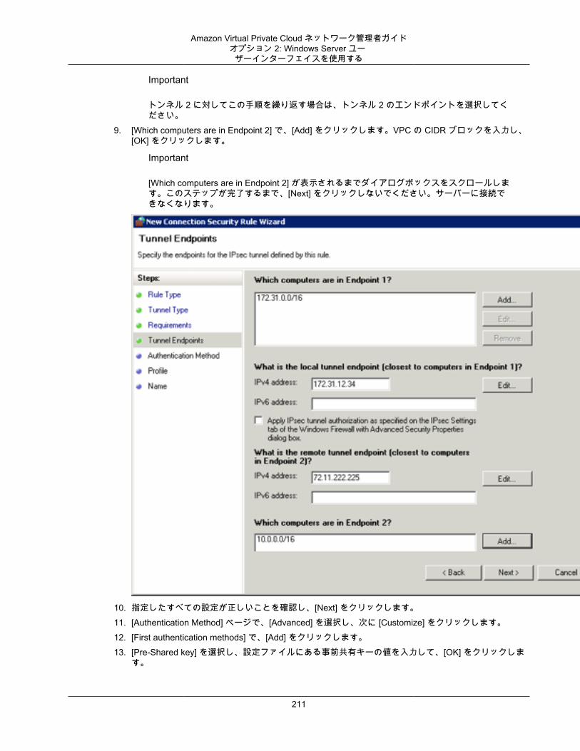
Amazon Virtual Private Cloud ネットワーク管理者ガイドオプション 2: Windows Server ユー
ザーインターフェイスを使用する
Important
トンネル 2 に対してこの手順を繰り返す場合は、トンネル 2 のエンドポイントを選択してください。
9. [Which computers are in Endpoint 2] で、[Add] をクリックします。VPC の CIDR ブロックを入力し、[OK] をクリックします。
Important
[Which computers are in Endpoint 2] が表示されるまでダイアログボックスをスクロールします。このステップが完了するまで、[Next] をクリックしないでください。サーバーに接続できなくなります。
10. 指定したすべての設定が正しいことを確認し、[Next] をクリックします。11. [Authentication Method] ページで、[Advanced] を選択し、次に [Customize] をクリックします。12. [First authentication methods] で、[Add] をクリックします。13. [Pre-Shared key] を選択し、設定ファイルにある事前共有キーの値を入力して、[OK] をクリックしま
す。
211
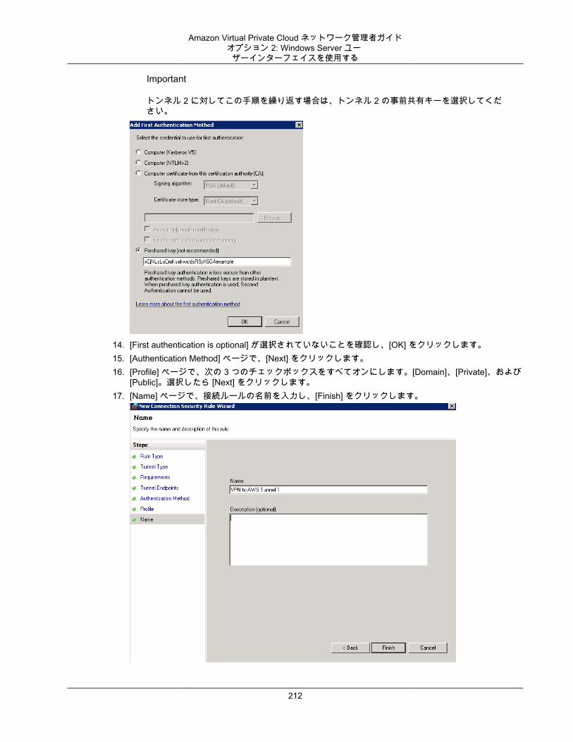
Amazon Virtual Private Cloud ネットワーク管理者ガイドオプション 2: Windows Server ユー
ザーインターフェイスを使用する
Important
トンネル 2 に対してこの手順を繰り返す場合は、トンネル 2 の事前共有キーを選択してください。
14. [First authentication is optional] が選択されていないことを確認し、[OK] をクリックします。15. [Authentication Method] ページで、[Next] をクリックします。16. [Profile] ページで、次の 3 つのチェックボックスをすべてオンにします。[Domain]、[Private]、および
[Public]。選択したら [Next] をクリックします。17. [Name] ページで、接続ルールの名前を入力し、[Finish] をクリックします。
212
Amazon Virtual Private Cloud ネットワーク管理者ガイドオプション 2: Windows Server ユー
ザーインターフェイスを使用する
上記の手順を繰り返し、設定ファイルにあるトンネル 2 のデータを指定します。
完了すると、VPN 接続に 2 つのトンネルが設定されます。
2.3: トンネルの設定を確認するトンネルの設定を確認するには
1. [サーバーマネージャ] ナビゲーションペインで、[Configuration] ノードを展開し、[Windows Firewallwith Advanced Security] を展開して、[Connection Security Rules] をクリックします。
2. 両方のトンネルについて次の設定を確認します。
• [Enabled] は Yes。• [Authentication mode] は Require inbound and clear outbound。• [Authentication method] は Custom。• [Endpoint 1 port] は Any。• [Endpoint 2 port] は Any。• [Protocol] は Any。
3. 1 番目のトンネルのセキュリティルールをダブルクリックします。4. [Computers] タブで、次の設定を確認します。
• [Endpoint 1] で、表示されている CIDR ブロック範囲が、使用しているネットワークの CIDR ブロック範囲と一致している。
• [Endpoint 2] で、表示されている CIDR ブロック範囲が、使用している VPC の CIDR ブロック範囲と一致している。
5. [Authentication] タブの [Method] で、[Customize] をクリックし、[First authentication methods] に、設定ファイルにあるトンネルの正しい事前共有キーが指定されていることを確認し、[OK] をクリックします。
6. [Advanced] タブで、[Domain]、[Private]、および [Public] がすべて選択されていることを確認します。
7. [IPsec tunneling] の [Customize] をクリックします。IPsec トンネリングが次のように設定されていることを確認します。
• [Use IPsec tunneling] が選択されている。• [Local tunnel endpoint (closest to Endpoint 1)] に、使用しているサーバーの IP アドレスが設定され
ている。カスタマーゲートウェイが Windows サーバーインスタンスである場合、これはインスタンスのプライベート IP アドレスです。
• [Remote tunnel endpoint (closest to Endpoint 2)] に、このトンネルの仮想プライベートゲートウェイの IP アドレスが設定されている。
8. 2 番目のトンネルのセキュリティルールをダブルクリックします。このトンネルに対してステップ 4から 7 までを繰り返します。
2.4: Windows ファイアウォールを設定するサーバーのセキュリティルールを設定した後、仮想プライベートゲートウェイと連動するように基本的なIPsec 設定を行います。
Windows ファイアウォールを設定するには
1. [Server Manager] ナビゲーションペインで、[Windows Firewall with Advanced Security] をクリックし、次に [Properties] をクリックします。
2. [IPsec Settings] タブをクリックします。
213
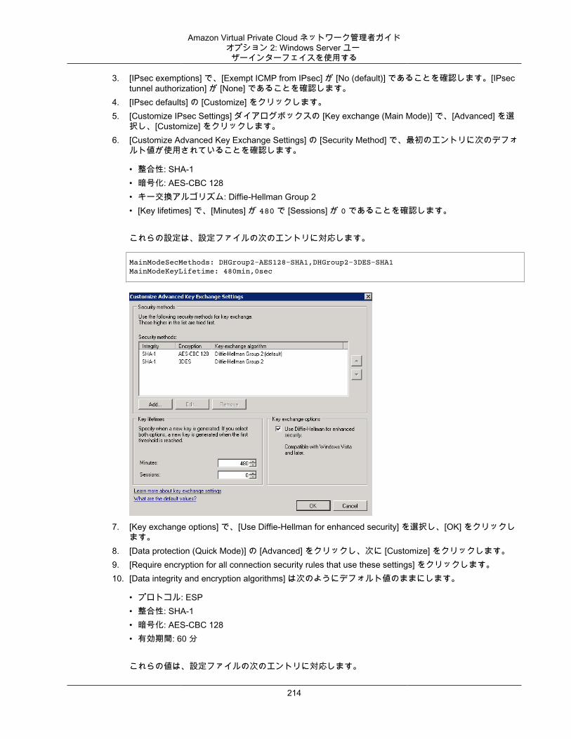
Amazon Virtual Private Cloud ネットワーク管理者ガイドオプション 2: Windows Server ユー
ザーインターフェイスを使用する
3. [IPsec exemptions] で、[Exempt ICMP from IPsec] が [No (default)] であることを確認します。[IPsectunnel authorization] が [None] であることを確認します。
4. [IPsec defaults] の [Customize] をクリックします。5. [Customize IPsec Settings] ダイアログボックスの [Key exchange (Main Mode)] で、[Advanced] を選
択し、[Customize] をクリックします。6. [Customize Advanced Key Exchange Settings] の [Security Method] で、最初のエントリに次のデフォ
ルト値が使用されていることを確認します。
• 整合性: SHA-1• 暗号化: AES-CBC 128• キー交換アルゴリズム: Diffie-Hellman Group 2• [Key lifetimes] で、[Minutes] が 480 で [Sessions] が 0 であることを確認します。
これらの設定は、設定ファイルの次のエントリに対応します。
MainModeSecMethods: DHGroup2-AES128-SHA1,DHGroup2-3DES-SHA1MainModeKeyLifetime: 480min,0sec
7. [Key exchange options] で、[Use Diffie-Hellman for enhanced security] を選択し、[OK] をクリックします。
8. [Data protection (Quick Mode)] の [Advanced] をクリックし、次に [Customize] をクリックします。9. [Require encryption for all connection security rules that use these settings] をクリックします。10. [Data integrity and encryption algorithms] は次のようにデフォルト値のままにします。
• プロトコル: ESP• 整合性: SHA-1• 暗号化: AES-CBC 128• 有効期間: 60 分
これらの値は、設定ファイルの次のエントリに対応します。
214
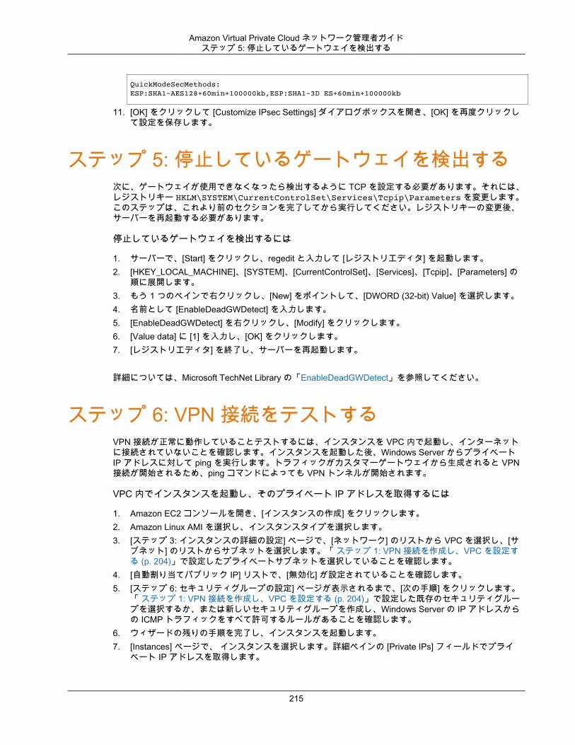
Amazon Virtual Private Cloud ネットワーク管理者ガイドステップ 5: 停止しているゲートウェイを検出する
QuickModeSecMethods: ESP:SHA1-AES128+60min+100000kb,ESP:SHA1-3D ES+60min+100000kb
11. [OK] をクリックして [Customize IPsec Settings] ダイアログボックスを開き、[OK] を再度クリックして設定を保存します。
ステップ 5: 停止しているゲートウェイを検出する次に、ゲートウェイが使用できなくなったら検出するように TCP を設定する必要があります。それには、レジストリキー HKLM\SYSTEM\CurrentControlSet\Services\Tcpip\Parameters を変更します。このステップは、これより前のセクションを完了してから実行してください。レジストリキーの変更後、サーバーを再起動する必要があります。
停止しているゲートウェイを検出するには
1. サーバーで、[Start] をクリックし、regedit と入力して [レジストリエディタ] を起動します。2. [HKEY_LOCAL_MACHINE]、[SYSTEM]、[CurrentControlSet]、[Services]、[Tcpip]、[Parameters] の
順に展開します。3. もう 1 つのペインで右クリックし、[New] をポイントして、[DWORD (32-bit) Value] を選択します。4. 名前として [EnableDeadGWDetect] を入力します。5. [EnableDeadGWDetect] を右クリックし、[Modify] をクリックします。6. [Value data] に [1] を入力し、[OK] をクリックします。7. [レジストリエディタ] を終了し、サーバーを再起動します。
詳細については、Microsoft TechNet Library の「EnableDeadGWDetect」を参照してください。
ステップ 6: VPN 接続をテストするVPN 接続が正常に動作していることテストするには、インスタンスを VPC 内で起動し、インターネットに接続されていないことを確認します。インスタンスを起動した後、Windows Server からプライベートIP アドレスに対して ping を実行します。トラフィックがカスタマーゲートウェイから生成されると VPN接続が開始されるため、ping コマンドによっても VPN トンネルが開始されます。
VPC 内でインスタンスを起動し、そのプライベート IP アドレスを取得するには
1. Amazon EC2 コンソールを開き、[インスタンスの作成] をクリックします。2. Amazon Linux AMI を選択し、インスタンスタイプを選択します。3. [ステップ 3: インスタンスの詳細の設定] ページで、[ネットワーク] のリストから VPC を選択し、[サ
ブネット] のリストからサブネットを選択します。「 ステップ 1: VPN 接続を作成し、VPC を設定する (p. 204)」で設定したプライベートサブネットを選択していることを確認します。
4. [自動割り当てパブリック IP] リストで、[無効化] が設定されていることを確認します。5. [ステップ 6: セキュリティグループの設定] ページが表示されるまで、[次の手順] をクリックします。
「 ステップ 1: VPN 接続を作成し、VPC を設定する (p. 204)」で設定した既存のセキュリティグループを選択するか、または新しいセキュリティグループを作成し、Windows Server の IP アドレスからの ICMP トラフィックをすべて許可するルールがあることを確認します。
6. ウィザードの残りの手順を完了し、インスタンスを起動します。7. [Instances] ページで、 インスタンスを選択します。詳細ペインの [Private IPs] フィールドでプライ
ベート IP アドレスを取得します。
215
Amazon Virtual Private Cloud ネットワーク管理者ガイドステップ 6: VPN 接続をテストする
Windows Server に接続またはログオンし、コマンドプロンプトを開いて、ping コマンドでインスタンスのプライベート IP アドレスを使用してインスタンスに ping を実行します。以下に例を示します。
ping 10.0.0.4
Pinging 10.0.0.4 with 32 bytes of data:Reply from 10.0.0.4: bytes=32 time=2ms TTL=62Reply from 10.0.0.4: bytes=32 time=2ms TTL=62Reply from 10.0.0.4: bytes=32 time=2ms TTL=62Reply from 10.0.0.4: bytes=32 time=2ms TTL=62 Ping statistics for 10.0.0.4: Packets: Sent = 4, Received = 4, Lost = 0 (0% loss),Approximate round trip times in milli-seconds: Minimum = 2ms, Maximum = 2ms, Average = 2ms
ping コマンドが失敗した場合、次の情報を確認します。
• VPC 内のインスタンスに対して ICMP が許容されるように、セキュリティグループのルールが設定されていることを確認します。Windows Server が EC2 インスタンスである場合は、セキュリティグループのアウトバウンドルールで IPsec トラフィックが許可されていることを確認します。詳細については、「Windows Server の設定 (p. 203)」を参照してください。
• ping 対象のインスタンスのオペレーティングシステムが ICMP に応答するように設定されていることを確認します。Amazon Linux AMI のいずれかを使用することをお勧めします。
• ping 対象のインスタンスが Windows インスタンスである場合は、インスタンスにログインし、Windows ファイアウォールでインバウンド ICMPv4 を有効にします。
• VPC またはサブネットのルートテーブルが正しく設定されていることを確認します。詳細については、「 ステップ 1: VPN 接続を作成し、VPC を設定する (p. 204)」を参照してください。
• カスタマーゲートウェイが Windows サーバーインスタンスである場合は、インスタンスに対して送信元/送信先チェックが無効になっていることを確認します。詳細については、「Windows Server の設定 (p. 203)」を参照してください。
Amazon VPC コンソールの [VPN Connections] ページで、使用している VPN 接続を選択します。1 番目のトンネルは起動状態です。2 番目のトンネルは、最初のトンネルが停止するまで使用されませんが、設定は必要です。暗号化されたトンネルを確立するのに数分かかることがあります。
216
Amazon Virtual Private Cloud ネットワーク管理者ガイドWindows Server の設定
Windows Server 2012 R2 のカスタマーゲートウェイとしての設定
Windows Server 2012 R2 を VPC 用のカスタマーゲートウェイとして設定できます。Windows Server2012 R2 を VPC 内の EC2 インスタンスで実行しているか独自のサーバーで実行しているかに関わらず、次のプロセスを使用します。
トピック• Windows Server の設定 (p. 217)• ステップ 1: VPN 接続を作成し、VPC を設定する (p. 218)• ステップ 2: VPN 接続の設定ファイルをダウンロードする (p. 219)• ステップ 3: Windows Server を設定する (p. 220)• ステップ 4: VPN トンネルを設定する (p. 221)• ステップ 5: 停止しているゲートウェイを検出する (p. 227)• ステップ 6: VPN 接続をテストする (p. 228)
Windows Server の設定Windows Server をカスタマーゲートウェイとして設定するには、Windows Server 2012 R2 を独自のネットワーク上に配置するか、VPC の EC2 インスタンス上に配置します。Windows AMI から起動した EC2インスタンスを使用している場合は、以下の作業を行います。
• インスタンスの送信元/送信先チェックを無効にします。1. https://console.aws.amazon.com/ec2/) にある Amazon EC2 コンソールを開きます。2. Windows Server インスタンスを選択して、[Actions] を選択し、次に [Networking] を選択して、
[Change Source/Dest.Check] を選択します。[Yes, Disable] を選択します。• 他のインスタンスからトラフィックをルーティングできるように、アダプタの設定を更新します。
1. Windows インスタンスに接続します。詳細については、「Windows インスタンスへの接続」を参照してください。
2. [コントロールパネル] を開き、[デバイスマネージャー] を起動します。3. [ネットワークアダプター] ノードを展開します。4. AWS PV ネットワークデバイスを選択して [アクション] を選択し、次に [プロパティ] を選択します。5. [詳細設定] タブで、[IPv4 Checksum Offload]、[TCP Checksum Offload (IPv4)]、および [UDP
Checksum Offload (IPv4)] の各プロパティを無効にし、[OK] を選択します。• Elastic IP アドレスとインスタンスを関連付けます。
1. https://console.aws.amazon.com/ec2/) にある Amazon EC2 コンソールを開きます。2. ナビゲーションペインで [Elastic IP] を選択します。[Allocate new address] を選択します。3. Elastic IP アドレスを選択し、[Actions]、[Associate Address] の順に選択します。4. [Instance] で、Windows Server インスタンスを選択します。[Associate] を選択します。
このアドレスは書き留めておきます。VPC でカスタマーゲートウェイを作成する際に必要になります。• インスタンスのセキュリティグループのルールでアウトバウンドの IPsec トラフィックが許可されてい
ることを確認します。デフォルトでは、セキュリティグループはすべてのアウトバウンドトラフィックを許可します。ただし、セキュリティグループのアウトバウンドルールが元の状態から変更されている
217
Amazon Virtual Private Cloud ネットワーク管理者ガイドステップ 1: VPN 接続を作成し、VPC を設定する
場合、IPsec トラフィック用にアウトバウンドのカスタムプロトコルルール (IP プロトコル 50、IP プロトコル 51、UDP 500) を作成する必要があります。
Windows Server が存在するネットワークの CIDR 範囲 (たとえば、172.31.0.0/16) をメモしておきます。
ステップ 1: VPN 接続を作成し、VPC を設定するVPC から VPN 接続を作成するには、まず仮想プライベートゲートウェイを作成し、それを VPC にアタッチする必要があります。その後、VPN 接続を作成し、VPC を設定することができます。Windows Serverが存在するネットワークの CIDR 範囲 (たとえば、172.31.0.0/16) も指定する必要があります。
仮想プライベートゲートウェイを作成するには
1. https://console.aws.amazon.com/vpc/にある Amazon VPC コンソールを開きます。2. ナビゲーションペインで [Virtual Private Gateways] を選択してから、[Create Virtual Private Gateway]
をクリックします。3. 任意で仮想プライベートゲートウェイの名前を入力し、[Yes, Create] を選択します。4. 作成した仮想プライベートゲートウェイを選択して、[Attach to VPC] を選択します。5. [Attach to VPC] ダイアログボックスのリストから VPC を選択してから、[Yes, Attach] を選択しま
す。
VPN 接続を作成するには
1. https://console.aws.amazon.com/vpc/にある Amazon VPC コンソールを開きます。2. ナビゲーションペインで [VPN 接続] を選択し、[VPN 接続の作成] を選択します。3. リストから仮想プライベートゲートウェイを選択します。4. [Customer Gateway] で、[New] を選択します。[IP address] で、Windows サーバーのパブリック IP
アドレスを指定します。
Note
この IP アドレスは静的である必要があります。また、ネットワークアドレス変換 (NAT) を実行するデバイスの背後のアドレスを使用することができます。NAT トラバーサル (NAT-T)を正しく機能させるには、UDP ポート 4500 のブロックを解除するようにファイアウォールのルールを調整する必要があります。カスタマーゲートウェイが EC2 Windows Server インスタンスである場合は、その Elastic IP アドレスを使用します。
5. ルーティングオプションとして [静的] を選択し、ネットワークの [静的 IP プレフィックス] の値をCIDR 表記で入力して、[作成] を選択します。
VPC を設定するには
• Windows サーバーと通信するインスタンスを起動するためのプライベートサブネットを VPC で作成します (まだ、ない場合)。詳細については、「VPC にサブネットを追加する」を参照してください。
Note
プライベートサブネットは、インターネットゲートウェイへのルートがないサブネットです。このサブネットのルーティングについては、次の項目で説明します。
• VPN 接続のルートテーブルを更新します。• 仮想プライベートゲートウェイをターゲットに指定し、Windows Server のネットワーク (CIDR 範囲)
を宛先に指定して、プライベートサブネットのルートテーブルにルートを追加します。
218
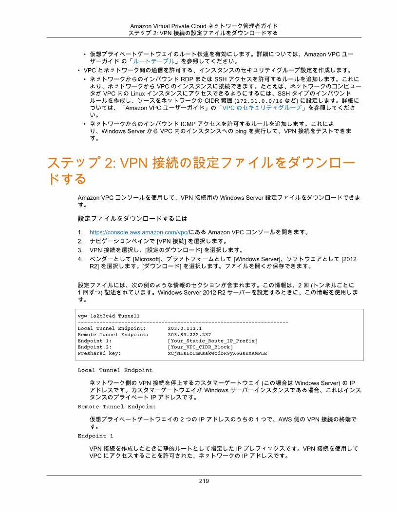
Amazon Virtual Private Cloud ネットワーク管理者ガイドステップ 2: VPN 接続の設定ファイルをダウンロードする
• 仮想プライベートゲートウェイのルート伝達を有効にします。詳細については、Amazon VPC ユーザーガイド の「ルートテーブル」を参照してください。
• VPC とネットワーク間の通信を許可する、インスタンスのセキュリティグループ設定を作成します。• ネットワークからのインバウンド RDP または SSH アクセスを許可するルールを追加します。これに
より、ネットワークから VPC のインスタンスに接続できます。たとえば、ネットワークのコンピュータが VPC 内の Linux インスタンスにアクセスできるようにするには、SSH タイプのインバウンドルールを作成し、ソースをネットワークの CIDR 範囲 (172.31.0.0/16 など) に設定します。詳細については、「Amazon VPC ユーザーガイド」の「VPC のセキュリティグループ」を参照してください。
• ネットワークからのインバウンド ICMP アクセスを許可するルールを追加します。これにより、Windows Server から VPC 内のインスタンスへの ping を実行して、VPN 接続をテストできます。
ステップ 2: VPN 接続の設定ファイルをダウンロードする
Amazon VPC コンソールを使用して、VPN 接続用の Windows Server 設定ファイルをダウンロードできます。
設定ファイルをダウンロードするには
1. https://console.aws.amazon.com/vpc/にある Amazon VPC コンソールを開きます。2. ナビゲーションペインで [VPN 接続] を選択します。3. VPN 接続を選択し、[設定のダウンロード] を選択します。4. ベンダーとして [Microsoft]、プラットフォームとして [Windows Server]、ソフトウェアとして [2012
R2] を選択します。[ダウンロード] を選択します。ファイルを開くか保存できます。
設定ファイルには、次の例のような情報のセクションが含まれます。この情報は、2 回 (トンネルごとに1 回ずつ) 記述されています。Windows Server 2012 R2 サーバーを設定するときに、この情報を使用します。
vgw-1a2b3c4d Tunnel1-------------------------------------------------------------------- Local Tunnel Endpoint: 203.0.113.1Remote Tunnel Endpoint: 203.83.222.237Endpoint 1: [Your_Static_Route_IP_Prefix]Endpoint 2: [Your_VPC_CIDR_Block]Preshared key: xCjNLsLoCmKsakwcdoR9yX6GsEXAMPLE
Local Tunnel Endpoint
ネットワーク側の VPN 接続を停止するカスタマーゲートウェイ (この場合は Windows Server) の IPアドレスです。カスタマーゲートウェイが Windows サーバーインスタンスである場合、これはインスタンスのプライベート IP アドレスです。
Remote Tunnel Endpoint
仮想プライベートゲートウェイの 2 つの IP アドレスのうちの 1 つで、AWS 側の VPN 接続の終端です。
Endpoint 1
VPN 接続を作成したときに静的ルートとして指定した IP プレフィックスです。VPN 接続を使用してVPC にアクセスすることを許可された、ネットワークの IP アドレスです。
219
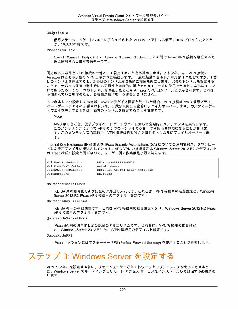
Amazon Virtual Private Cloud ネットワーク管理者ガイドステップ 3: Windows Server を設定する
Endpoint 2
仮想プライベートゲートウェイにアタッチされた VPC の IP アドレス範囲 (CIDR ブロック) (たとえば、10.0.0.0/16) です。
Preshared key
Local Tunnel Endpoint と Remote Tunnel Endpoint との間で IPsec VPN 接続を確立するために使用される事前共有キーです。
両方のトンネルを VPN 接続の一部として設定することをお勧めします。各トンネルは、VPN 接続のAmazon 側にある別個の VPN コネクタに接続します。一度に起動できるトンネルは 1 つだけですが、1 番目のトンネルが停止すると、2 番目のトンネルが自動的に接続を確立します。冗長なトンネルを設定することで、デバイス障害の発生時にも可用性を継続的に維持できます。一度に使用できるトンネルは 1 つだけであるため、その 1 つのトンネルが停止したことが Amazon VPC コンソールに表示されます。これは予期されている動作のため、お客様が操作を行う必要はありません。
トンネルを 2 つ設定しておけば、AWS でデバイス障害が発生した場合、VPN 接続は AWS 仮想プライベートゲートウェイの 2 番目のトンネルに数分以内に自動的にフェイルオーバーします。カスタマーゲートウェイを設定するときは、両方のトンネルを設定することが重要です。
Note
AWS はときどき、仮想プライベートゲートウェイに対して定期的にメンテナンスを実行します。このメンテナンスによって VPN の 2 つのトンネルのうち 1 つが短時間無効になることがあります。このメンテナンスの実行中、VPN 接続は自動的に 2 番目のトンネルにフェイルオーバーします。
Internet Key Exchange (IKE) および IPsec Security Associations (SA) についての追加情報が、ダウンロードした設定ファイルに記述されています。VPC VPN の推奨設定は Windows Server 2012 R2 のデフォルトの IPsec 構成の設定と同じなので、ユーザー側の作業は最小限で済みます。
MainModeSecMethods: DHGroup2-AES128-SHA1MainModeKeyLifetime: 480min,0sessQuickModeSecMethods: ESP:SHA1-AES128+60min+100000kbQuickModePFS: DHGroup2
MainModeSecMethods
IKE SA 用の暗号化および認証のアルゴリズムです。これらは、VPN 接続用の推奨設定と、WindowsServer 2012 R2 IPsec VPN 接続用のデフォルト設定です。
MainModeKeyLifetime
IKE SA キーの有効期間です。これは VPN 接続用の推奨設定であり、Windows Server 2012 R2 IPsecVPN 接続用のデフォルト設定です。
QuickModeSecMethods
IPsec SA 用の暗号化および認証のアルゴリズムです。これらは、VPN 接続用の推奨設定と、Windows Server 2012 R2 IPsec VPN 接続用のデフォルト設定です。
QuickModePFS
IPsec セッションにはマスターキー PFS (Perfect Forward Secrecy) を使用することを推奨します。
ステップ 3: Windows Server を設定するVPN トンネルを設定する前に、リモートユーザーがネットワーク上のリソースにアクセスできるように、Windows Server でルーティングとリモート アクセス サービスをインストールして設定する必要があります。
220
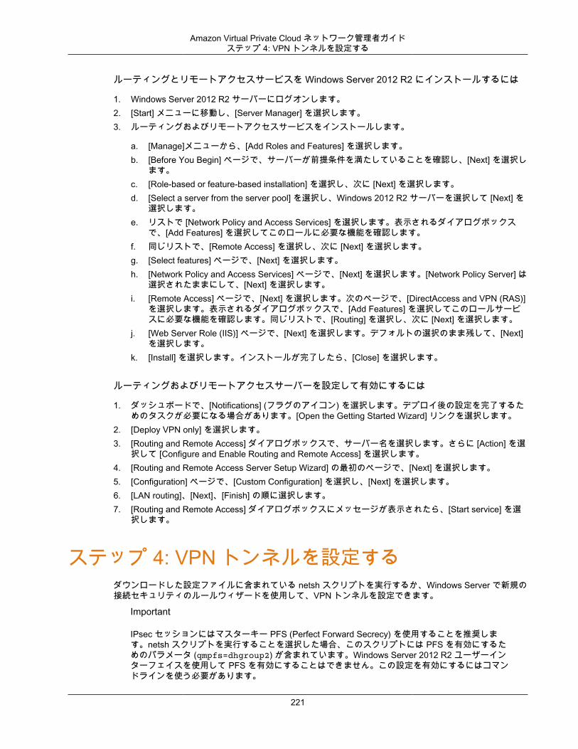
Amazon Virtual Private Cloud ネットワーク管理者ガイドステップ 4: VPN トンネルを設定する
ルーティングとリモートアクセスサービスを Windows Server 2012 R2 にインストールするには
1. Windows Server 2012 R2 サーバーにログオンします。2. [Start] メニューに移動し、[Server Manager] を選択します。3. ルーティングおよびリモートアクセスサービスをインストールします。
a. [Manage]メニューから、[Add Roles and Features] を選択します。b. [Before You Begin] ページで、サーバーが前提条件を満たしていることを確認し、[Next] を選択し
ます。c. [Role-based or feature-based installation] を選択し、次に [Next] を選択します。d. [Select a server from the server pool] を選択し、Windows 2012 R2 サーバーを選択して [Next] を
選択します。e. リストで [Network Policy and Access Services] を選択します。表示されるダイアログボックス
で、[Add Features] を選択してこのロールに必要な機能を確認します。f. 同じリストで、[Remote Access] を選択し、次に [Next] を選択します。g. [Select features] ページで、[Next] を選択します。h. [Network Policy and Access Services] ページで、[Next] を選択します。[Network Policy Server] は
選択されたままにして、[Next] を選択します。i. [Remote Access] ページで、[Next] を選択します。次のページで、[DirectAccess and VPN (RAS)]
を選択します。表示されるダイアログボックスで、[Add Features] を選択してこのロールサービスに必要な機能を確認します。同じリストで、[Routing] を選択し、次に [Next] を選択します。
j. [Web Server Role (IIS)] ページで、[Next] を選択します。デフォルトの選択のまま残して、[Next]を選択します。
k. [Install] を選択します。インストールが完了したら、[Close] を選択します。
ルーティングおよびリモートアクセスサーバーを設定して有効にするには
1. ダッシュボードで、[Notifications] (フラグのアイコン) を選択します。デプロイ後の設定を完了するためのタスクが必要になる場合があります。[Open the Getting Started Wizard] リンクを選択します。
2. [Deploy VPN only] を選択します。3. [Routing and Remote Access] ダイアログボックスで、サーバー名を選択します。さらに [Action] を選
択して [Configure and Enable Routing and Remote Access] を選択します。4. [Routing and Remote Access Server Setup Wizard] の最初のページで、[Next] を選択します。5. [Configuration] ページで、[Custom Configuration] を選択し、[Next] を選択します。6. [LAN routing]、[Next]、[Finish] の順に選択します。7. [Routing and Remote Access] ダイアログボックスにメッセージが表示されたら、[Start service] を選
択します。
ステップ 4: VPN トンネルを設定するダウンロードした設定ファイルに含まれている netsh スクリプトを実行するか、Windows Server で新規の接続セキュリティのルールウィザードを使用して、VPN トンネルを設定できます。
Important
IPsec セッションにはマスターキー PFS (Perfect Forward Secrecy) を使用することを推奨します。netsh スクリプトを実行することを選択した場合、このスクリプトには PFS を有効にするためのパラメータ (qmpfs=dhgroup2) が含まれています。Windows Server 2012 R2 ユーザーインターフェイスを使用して PFS を有効にすることはできません。この設定を有効にするにはコマンドラインを使う必要があります。
221
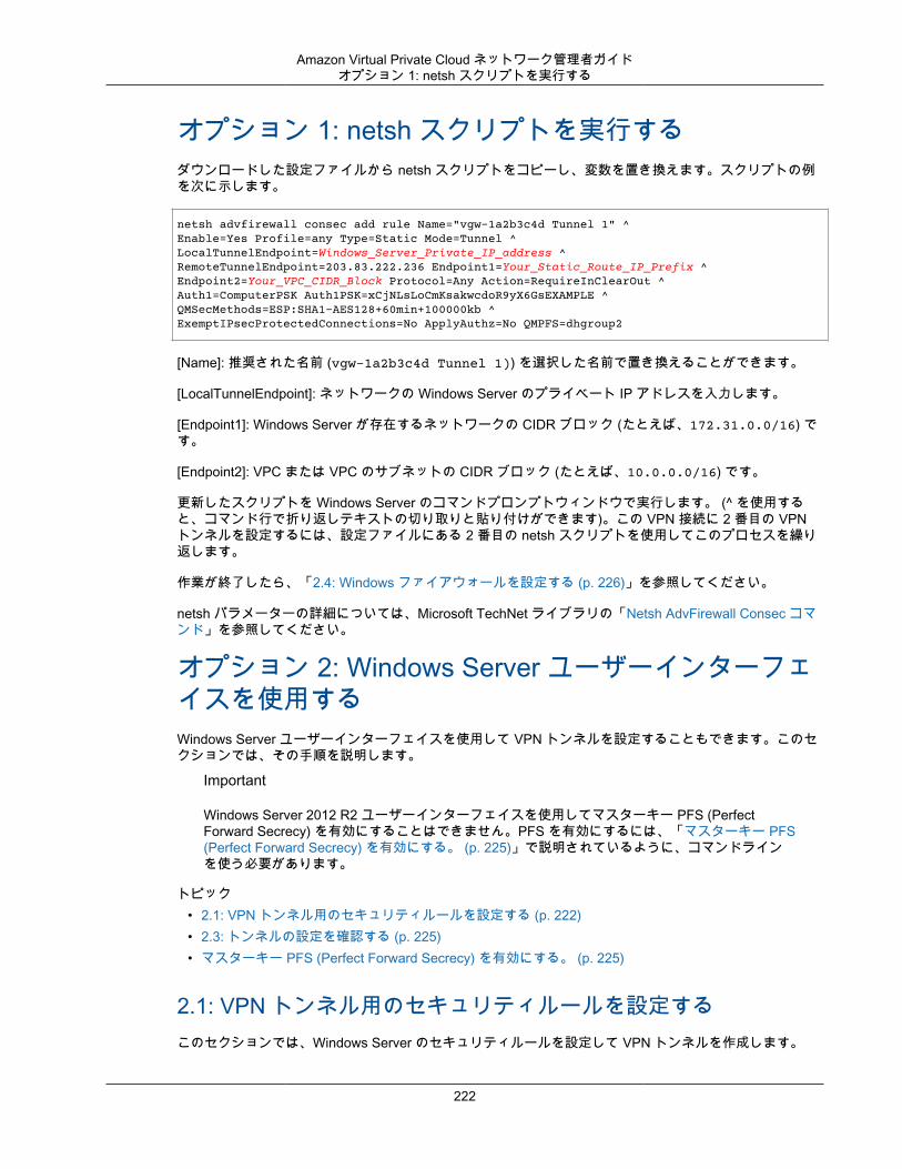
Amazon Virtual Private Cloud ネットワーク管理者ガイドオプション 1: netsh スクリプトを実行する
オプション 1: netsh スクリプトを実行するダウンロードした設定ファイルから netsh スクリプトをコピーし、変数を置き換えます。スクリプトの例を次に示します。
netsh advfirewall consec add rule Name="vgw-1a2b3c4d Tunnel 1" ^Enable=Yes Profile=any Type=Static Mode=Tunnel ^LocalTunnelEndpoint=Windows_Server_Private_IP_address ^RemoteTunnelEndpoint=203.83.222.236 Endpoint1=Your_Static_Route_IP_Prefix ^Endpoint2=Your_VPC_CIDR_Block Protocol=Any Action=RequireInClearOut ^Auth1=ComputerPSK Auth1PSK=xCjNLsLoCmKsakwcdoR9yX6GsEXAMPLE ^QMSecMethods=ESP:SHA1-AES128+60min+100000kb ^ExemptIPsecProtectedConnections=No ApplyAuthz=No QMPFS=dhgroup2
[Name]: 推奨された名前 (vgw-1a2b3c4d Tunnel 1)) を選択した名前で置き換えることができます。
[LocalTunnelEndpoint]: ネットワークの Windows Server のプライベート IP アドレスを入力します。
[Endpoint1]: Windows Server が存在するネットワークの CIDR ブロック (たとえば、172.31.0.0/16) です。
[Endpoint2]: VPC または VPC のサブネットの CIDR ブロック (たとえば、10.0.0.0/16) です。
更新したスクリプトを Windows Server のコマンドプロンプトウィンドウで実行します。 (^ を使用すると、コマンド行で折り返しテキストの切り取りと貼り付けができます)。この VPN 接続に 2 番目の VPNトンネルを設定するには、設定ファイルにある 2 番目の netsh スクリプトを使用してこのプロセスを繰り返します。
作業が終了したら、「2.4: Windows ファイアウォールを設定する (p. 226)」を参照してください。
netsh パラメーターの詳細については、Microsoft TechNet ライブラリの「Netsh AdvFirewall Consec コマンド」を参照してください。
オプション 2: Windows Server ユーザーインターフェイスを使用するWindows Server ユーザーインターフェイスを使用して VPN トンネルを設定することもできます。このセクションでは、その手順を説明します。
Important
Windows Server 2012 R2 ユーザーインターフェイスを使用してマスターキー PFS (PerfectForward Secrecy) を有効にすることはできません。PFS を有効にするには、「マスターキー PFS(Perfect Forward Secrecy) を有効にする。 (p. 225)」で説明されているように、コマンドラインを使う必要があります。
トピック• 2.1: VPN トンネル用のセキュリティルールを設定する (p. 222)• 2.3: トンネルの設定を確認する (p. 225)• マスターキー PFS (Perfect Forward Secrecy) を有効にする。 (p. 225)
2.1: VPN トンネル用のセキュリティルールを設定するこのセクションでは、Windows Server のセキュリティルールを設定して VPN トンネルを作成します。
222
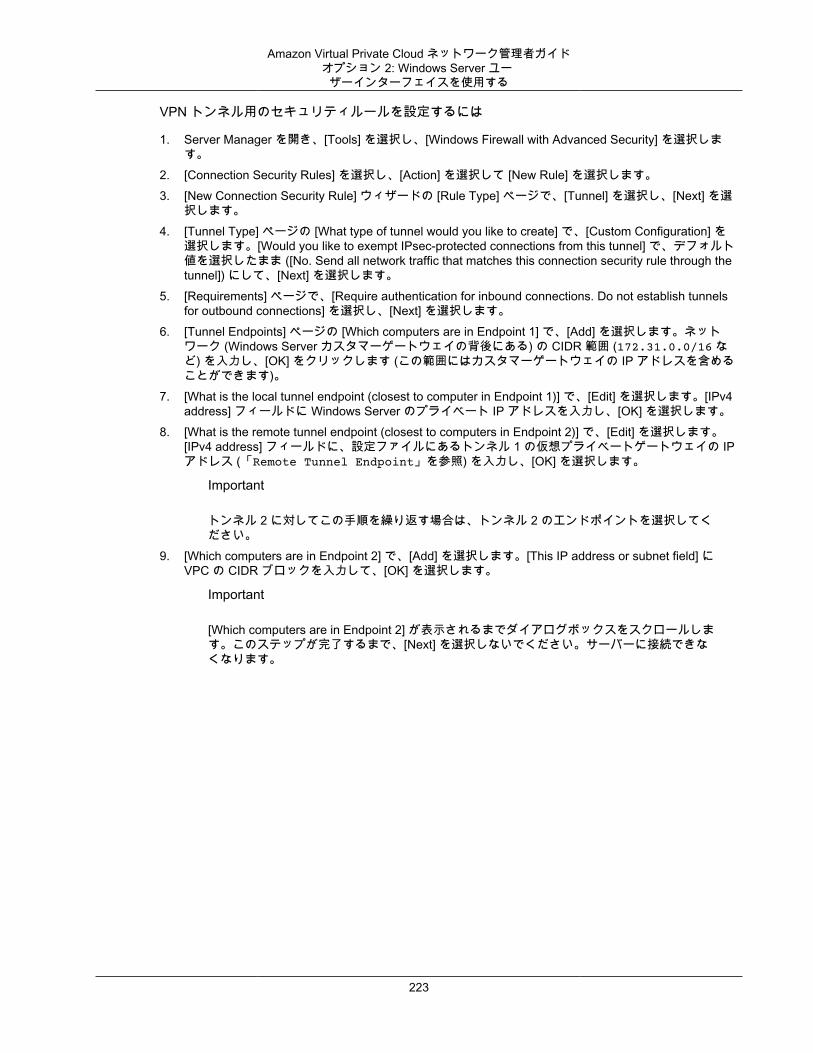
Amazon Virtual Private Cloud ネットワーク管理者ガイドオプション 2: Windows Server ユー
ザーインターフェイスを使用する
VPN トンネル用のセキュリティルールを設定するには
1. Server Manager を開き、[Tools] を選択し、[Windows Firewall with Advanced Security] を選択します。
2. [Connection Security Rules] を選択し、[Action] を選択して [New Rule] を選択します。3. [New Connection Security Rule] ウィザードの [Rule Type] ページで、[Tunnel] を選択し、[Next] を選
択します。4. [Tunnel Type] ページの [What type of tunnel would you like to create] で、[Custom Configuration] を
選択します。[Would you like to exempt IPsec-protected connections from this tunnel] で、デフォルト値を選択したまま ([No. Send all network traffic that matches this connection security rule through thetunnel]) にして、[Next] を選択します。
5. [Requirements] ページで、[Require authentication for inbound connections. Do not establish tunnelsfor outbound connections] を選択し、[Next] を選択します。
6. [Tunnel Endpoints] ページの [Which computers are in Endpoint 1] で、[Add] を選択します。ネットワーク (Windows Server カスタマーゲートウェイの背後にある) の CIDR 範囲 (172.31.0.0/16 など) を入力し、[OK] をクリックします (この範囲にはカスタマーゲートウェイの IP アドレスを含めることができます)。
7. [What is the local tunnel endpoint (closest to computer in Endpoint 1)] で、[Edit] を選択します。[IPv4address] フィールドに Windows Server のプライベート IP アドレスを入力し、[OK] を選択します。
8. [What is the remote tunnel endpoint (closest to computers in Endpoint 2)] で、[Edit] を選択します。[IPv4 address] フィールドに、設定ファイルにあるトンネル 1 の仮想プライベートゲートウェイの IPアドレス (「Remote Tunnel Endpoint」を参照) を入力し、[OK] を選択します。
Important
トンネル 2 に対してこの手順を繰り返す場合は、トンネル 2 のエンドポイントを選択してください。
9. [Which computers are in Endpoint 2] で、[Add] を選択します。[This IP address or subnet field] にVPC の CIDR ブロックを入力して、[OK] を選択します。
Important
[Which computers are in Endpoint 2] が表示されるまでダイアログボックスをスクロールします。このステップが完了するまで、[Next] を選択しないでください。サーバーに接続できなくなります。
223
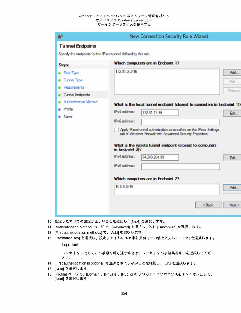
Amazon Virtual Private Cloud ネットワーク管理者ガイドオプション 2: Windows Server ユー
ザーインターフェイスを使用する
10. 指定したすべての設定が正しいことを確認し、[Next] を選択します。11. [Authentication Method] ページで、[Advanced] を選択し、次に [Customize] を選択します。12. [First authentication methods] で、[Add] を選択します。13. [Preshared key] を選択し、設定ファイルにある事前共有キーの値を入力して、[OK] を選択します。
Important
トンネル 2 に対してこの手順を繰り返す場合は、トンネル 2 の事前共有キーを選択してください。
14. [First authentication is optional] が選択されていないことを確認し、[OK] を選択します。15. [Next] を選択します。16. [Profile] ページで、[Domain]、[Private]、[Public] の 3 つのチェックボックスをすべてオンにして、
[Next] を選択します。
224
Amazon Virtual Private Cloud ネットワーク管理者ガイドオプション 2: Windows Server ユー
ザーインターフェイスを使用する
17. [Name] ページで、接続ルールの名前 (VPN to AWS Tunnel 1 など) を入力し、[Finish] を選択します。
上記の手順を繰り返し、設定ファイルにあるトンネル 2 のデータを指定します。
完了すると、VPN 接続に 2 つのトンネルが設定されます。
2.3: トンネルの設定を確認するトンネルの設定を確認するには
1. Server Manager を開き、[Tools] を選択して、[Windows Firewall with Advanced Security] を選択します。次に [Connection Security Rules] を選択します。
2. 両方のトンネルについて次の設定を確認します。
• [Enabled] は Yes。• [Endpoint 1] はネットワークの CIDR ブロックです。• [Endpoint 2] は VPC の CIDR ブロックです。• [Authentication mode] は Require inbound and clear outbound。• [Authentication method] は Custom。• [Endpoint 1 port] は Any。• [Endpoint 2 port] は Any。• [Protocol] は Any。
3. 最初のルールを選択し、[Properties] を選択します。4. [Authentication] タブの [Method] で、[Customize] を選択し、[First authentication methods] に、設定
ファイルにあるトンネルの正しい事前共有キーが指定されていることを確認し、[OK] を選択します。5. [Advanced] タブで、[Domain]、[Private]、および [Public] がすべて選択されていることを確認しま
す。6. [IPsec tunneling] の [Customize] を選択します。IPsec トンネリングが次のように設定されていること
を確認して [OK] を選択します。再度 [OK] を選択してダイアログボックスを閉じます。
• [Use IPsec tunneling] が選択されている。• [Local tunnel endpoint (closest to Endpoint 1)] に、Windows Server の IP アドレスが設定されてい
る。カスタマーゲートウェイが EC2 インスタンスである場合、これはインスタンスのプライベートIP アドレスです。
• [Remote tunnel endpoint (closest to Endpoint 2)] に、このトンネルの仮想プライベートゲートウェイの IP アドレスが設定されている。
7. 2 番目のトンネルのプロパティを開きます。このトンネルに対してステップ 4 から 7 までを繰り返します。
マスターキー PFS (Perfect Forward Secrecy) を有効にする。マスターキー PFS (Perfect Forward Secrecy) を有効にするにはコマンドラインを使用できます。ユーザーインターフェイスを使用してこの機能を有効にすることはできません。
マスターキー PFS (Perfect Forward Secrecy) を有効にするには
1. Windows Server で、新しいコマンドプロンプトウィンドウを開きます。2. 次のコマンドを入力します。rule_name は最初の接続ルールに指定した名前に置き換えます。
netsh advfirewall consec set rule name="rule_name" new QMPFS=dhgroup2 QMSecMethods=ESP:SHA1-AES128+60min+100000kb
225
Amazon Virtual Private Cloud ネットワーク管理者ガイド2.4: Windows ファイアウォールを設定する
3. 2 番目のトンネルにステップ 2 を繰り返します。今回は rule_name を 2 番目の接続ルールに指定した名前に置き換えます。
2.4: Windows ファイアウォールを設定するサーバーのセキュリティルールを設定した後、仮想プライベートゲートウェイと連動するように基本的なIPsec 設定を行います。
Windows ファイアウォールを設定するには
1. Server Manager を開き、[Tools] を選択して [Windows Firewall with Advanced Security] を選択します。次に [Properties] を選択します。
2. [IPsec Settings] タブの [IPsec exemptions] で、[Exempt ICMP from IPsec] が [No (default)] になっていることを確認します。[IPsec tunnel authorization] が [None] であることを確認します。
3. [IPsec defaults] の [Customize] を選択します。4. [Key exchange (Main Mode)] の [Advanced] を選択し、[Customize] を選択します。5. [Customize Advanced Key Exchange Settings] の [Security Method] で、最初のエントリに次のデフォ
ルト値が使用されていることを確認します。
• 整合性: SHA-1• 暗号化: AES-CBC 128• キー交換アルゴリズム: Diffie-Hellman Group 2• [Key lifetimes] で、[Minutes] が 480 で [Sessions] が 0 であることを確認します。
これらの設定は、設定ファイルの次のエントリに対応します。
MainModeSecMethods: DHGroup2-AES128-SHA1,DHGroup2-3DES-SHA1MainModeKeyLifetime: 480min,0sec
6. [Key exchange options] の [Use Diffie-Hellman for enhanced security] を選択し、[OK] を選択します。7. [Data protection (Quick Mode)] の [Advanced] を選択し、[Customize] を選択します。8. [Require encryption for all connection security rules that use these settings] を選択します。9. [Data integrity and encryption ] は次のようにデフォルト値のままにします。
• プロトコル: ESP• 整合性: SHA-1• 暗号化: AES-CBC 128• 有効期間: 60 分
これらの値は、設定ファイルの次のエントリに対応します。
QuickModeSecMethods: ESP:SHA1-AES128+60min+100000kb
10. [OK] を選択して [Customize IPsec Settings] ダイアログボックスに戻り、再度 [OK] を選択して設定を保存します。
226
Amazon Virtual Private Cloud ネットワーク管理者ガイドステップ 5: 停止しているゲートウェイを検出する
ステップ 5: 停止しているゲートウェイを検出する次に、ゲートウェイが使用できなくなったら検出するように TCP を設定する必要があります。それには、レジストリキー HKLM\SYSTEM\CurrentControlSet\Services\Tcpip\Parameters を変更します。このステップは、これより前のセクションを完了してから実行してください。レジストリキーの変更後、サーバーを再起動する必要があります。
停止しているゲートウェイを検出するには
1. Windows Server でコマンドプロンプトまたは PowerShell セッションを起動し、「regedit」と入力してレジストリエディタを起動します。
2. [HKEY_LOCAL_MACHINE]、[SYSTEM]、[CurrentControlSet]、[Services]、[Tcpip]、[Parameters] の順に展開します。
3. [Edit] メニューの [New] を選択し、[DWORD (32-bit) Value] を選択します。4. 名前として [EnableDeadGWDetect] を入力します。5. [EnableDeadGWDetect] を選択し、[Edit] メニューの [Modify] を選択します。6. [Value data] に「1」と入力し、[OK] を選択します。7. レジストリエディタを終了し、サーバーを再起動します。
詳細については、Microsoft TechNet Library の「EnableDeadGWDetect」を参照してください。
227
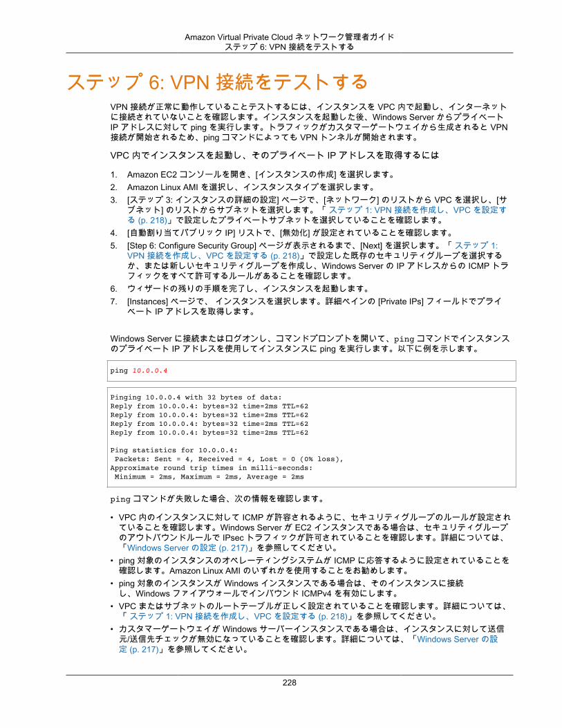
Amazon Virtual Private Cloud ネットワーク管理者ガイドステップ 6: VPN 接続をテストする
ステップ 6: VPN 接続をテストするVPN 接続が正常に動作していることテストするには、インスタンスを VPC 内で起動し、インターネットに接続されていないことを確認します。インスタンスを起動した後、Windows Server からプライベートIP アドレスに対して ping を実行します。トラフィックがカスタマーゲートウェイから生成されると VPN接続が開始されるため、ping コマンドによっても VPN トンネルが開始されます。
VPC 内でインスタンスを起動し、そのプライベート IP アドレスを取得するには
1. Amazon EC2 コンソールを開き、[インスタンスの作成] を選択します。2. Amazon Linux AMI を選択し、インスタンスタイプを選択します。3. [ステップ 3: インスタンスの詳細の設定] ページで、[ネットワーク] のリストから VPC を選択し、[サ
ブネット] のリストからサブネットを選択します。「 ステップ 1: VPN 接続を作成し、VPC を設定する (p. 218)」で設定したプライベートサブネットを選択していることを確認します。
4. [自動割り当てパブリック IP] リストで、[無効化] が設定されていることを確認します。5. [Step 6: Configure Security Group] ページが表示されるまで、[Next] を選択します。「 ステップ 1:
VPN 接続を作成し、VPC を設定する (p. 218)」で設定した既存のセキュリティグループを選択するか、または新しいセキュリティグループを作成し、Windows Server の IP アドレスからの ICMP トラフィックをすべて許可するルールがあることを確認します。
6. ウィザードの残りの手順を完了し、インスタンスを起動します。7. [Instances] ページで、 インスタンスを選択します。詳細ペインの [Private IPs] フィールドでプライ
ベート IP アドレスを取得します。
Windows Server に接続またはログオンし、コマンドプロンプトを開いて、ping コマンドでインスタンスのプライベート IP アドレスを使用してインスタンスに ping を実行します。以下に例を示します。
ping 10.0.0.4
Pinging 10.0.0.4 with 32 bytes of data:Reply from 10.0.0.4: bytes=32 time=2ms TTL=62Reply from 10.0.0.4: bytes=32 time=2ms TTL=62Reply from 10.0.0.4: bytes=32 time=2ms TTL=62Reply from 10.0.0.4: bytes=32 time=2ms TTL=62 Ping statistics for 10.0.0.4: Packets: Sent = 4, Received = 4, Lost = 0 (0% loss),Approximate round trip times in milli-seconds: Minimum = 2ms, Maximum = 2ms, Average = 2ms
ping コマンドが失敗した場合、次の情報を確認します。
• VPC 内のインスタンスに対して ICMP が許容されるように、セキュリティグループのルールが設定されていることを確認します。Windows Server が EC2 インスタンスである場合は、セキュリティグループのアウトバウンドルールで IPsec トラフィックが許可されていることを確認します。詳細については、「Windows Server の設定 (p. 217)」を参照してください。
• ping 対象のインスタンスのオペレーティングシステムが ICMP に応答するように設定されていることを確認します。Amazon Linux AMI のいずれかを使用することをお勧めします。
• ping 対象のインスタンスが Windows インスタンスである場合は、そのインスタンスに接続し、Windows ファイアウォールでインバウンド ICMPv4 を有効にします。
• VPC またはサブネットのルートテーブルが正しく設定されていることを確認します。詳細については、「 ステップ 1: VPN 接続を作成し、VPC を設定する (p. 218)」を参照してください。
• カスタマーゲートウェイが Windows サーバーインスタンスである場合は、インスタンスに対して送信元/送信先チェックが無効になっていることを確認します。詳細については、「Windows Server の設定 (p. 217)」を参照してください。
228

Amazon Virtual Private Cloud ネットワーク管理者ガイドステップ 6: VPN 接続をテストする
Amazon VPC コンソールの [VPN Connections] ページで、使用している VPN 接続を選択します。1 番目のトンネルは起動状態です。2 番目のトンネルは、最初のトンネルが停止するまで使用されませんが、設定は必要です。暗号化されたトンネルを確立するのに数分かかることがあります。
229

Amazon Virtual Private Cloud ネットワーク管理者ガイド
ドキュメント履歴Amazon VPC ネットワーク管理者ガイドの各リリースにおける重要な変更点の詳細については、AmazonVPC ユーザーガイドの「ドキュメント履歴」を参照してください。
230